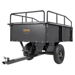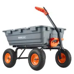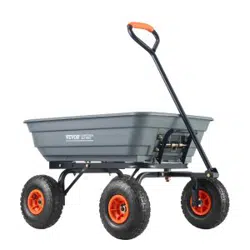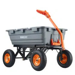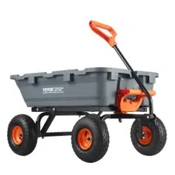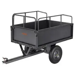

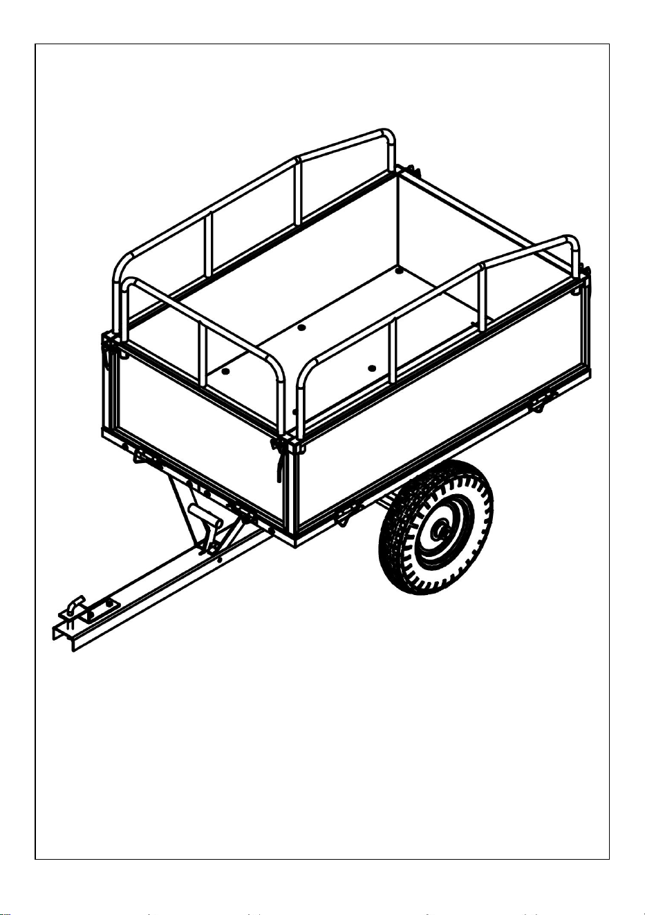
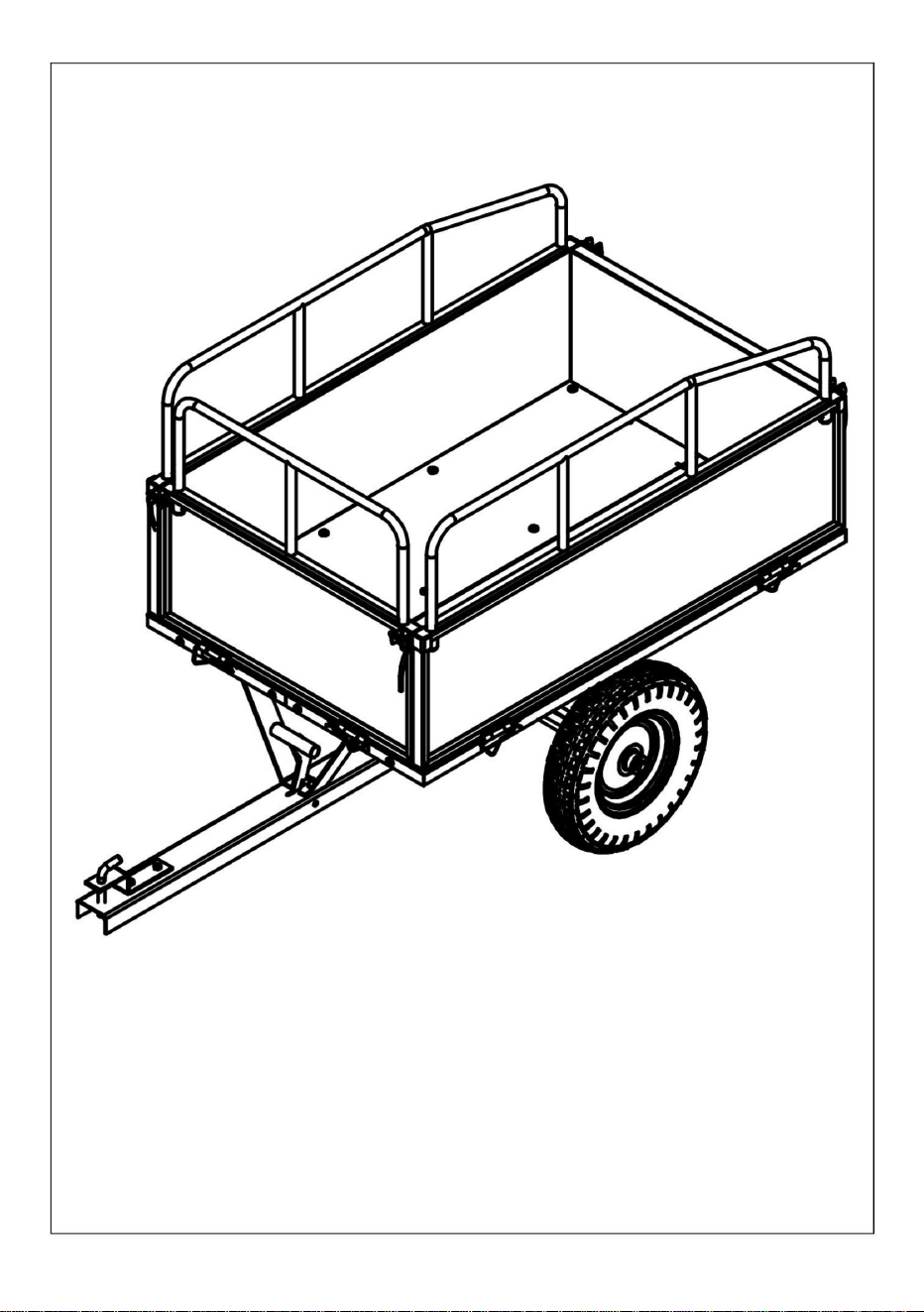
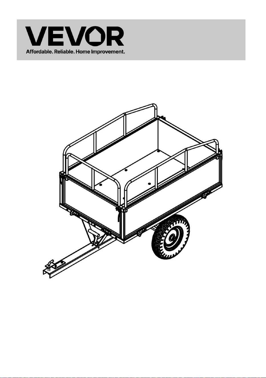
GARDEN TRAILERS
MODEL: BTC002D/BTC002E


- 1 -
MODEL: BTC002D/BTC002E
This is the original instruction, please read all manual instructions carefully
before operating. VEVOR reserves a clear interpretation of our user
manual. The appearance of the product shall be subject to the product you
received. Please forgive us that we won't inform you again if there are any
technology or software updates on our product.
GARDEN TRAILERS

- 2 -
SAFETY INSTRUCTIONS
WARNING:
Read this material before using this product. Failure to do so can
result in serious injury.
Assembly precautions
1. Assemble only according to these instructions. Improper assembly can
create hazards.
2. Wear ANSI-approved safety goggles and heavy-duty work gloves
during assembly.
3. Keep the assembly area clean and well-lit.
4. Keep bystanders out of the area during assembly.
5. Do not assemble if tired or when under the influence of alcohol, drugs
or medication.
6. The product capabilities apply to properly and completely assembled
products only.
Assemble on a flat, level, hard and smooth surface capable of safely
supporting the Garden Trailers
7. For additional information regarding the parts listed in the following
pages, please refer to the Assembly Diagram of this manual. Unwrap
and separate all parts in a clean work area.
Use precautions
1. DO NOT SIT OR STAND ON THIS ITEM.
2. This product is not a toy. Do not allow children to play with or near this
item.
3. Do not exceed specified weight capacities.
4. Use as intended only.
5. Inspect before every use; do not use if parts are loose or damaged.
SAVE THIS MANUAL
- 3 -
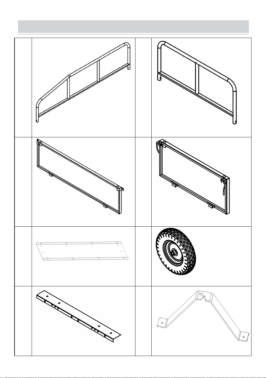
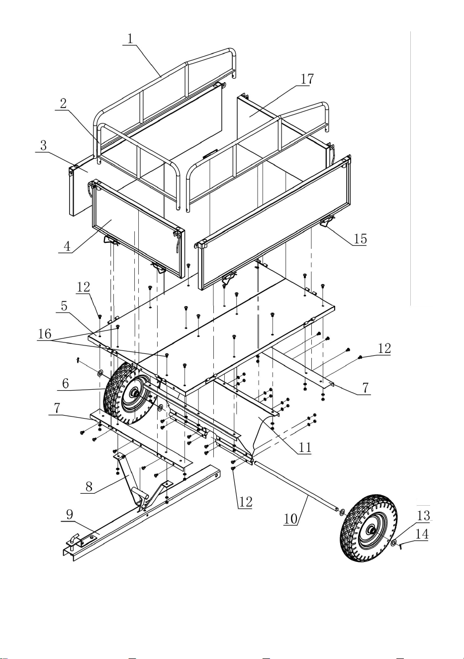
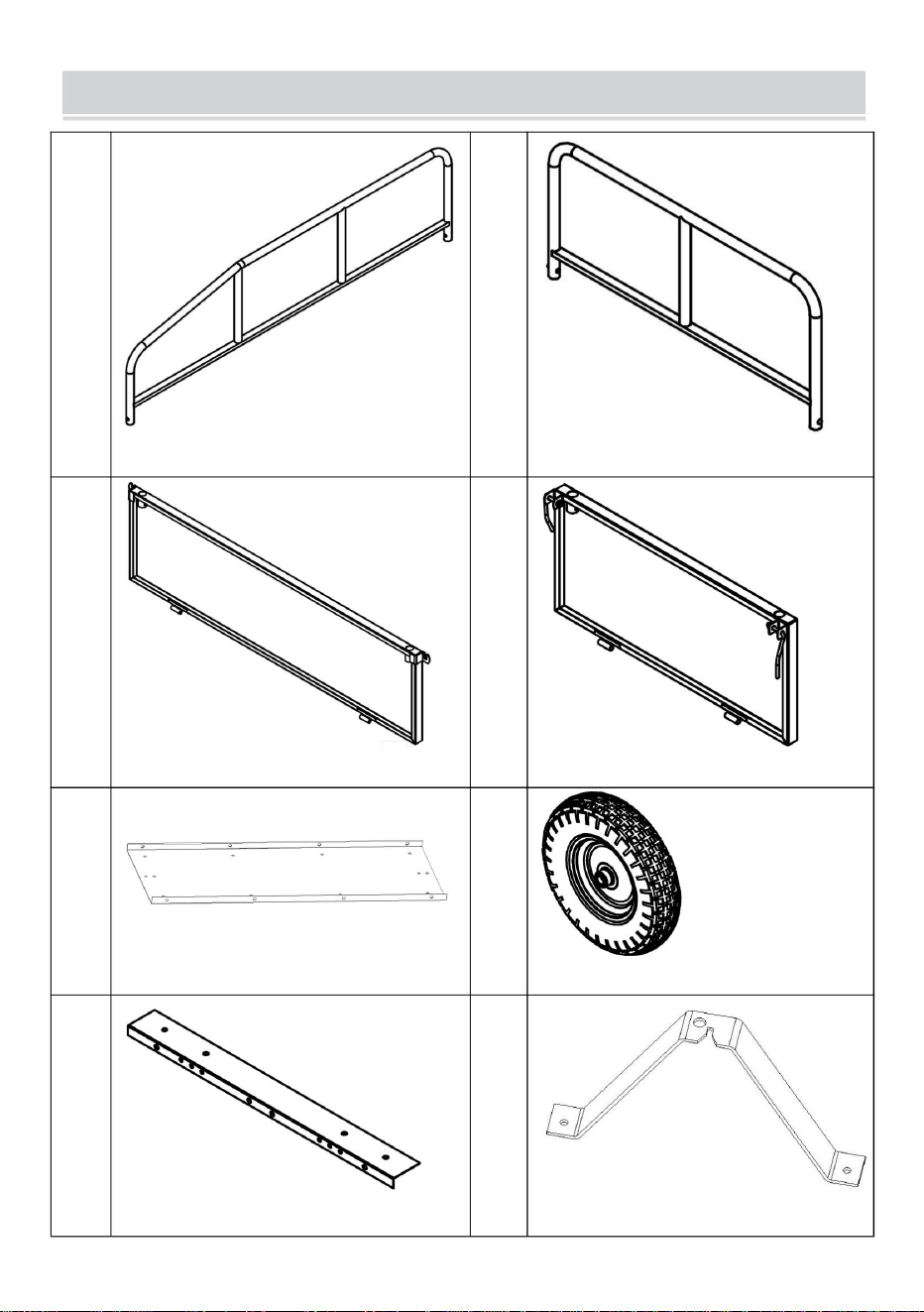
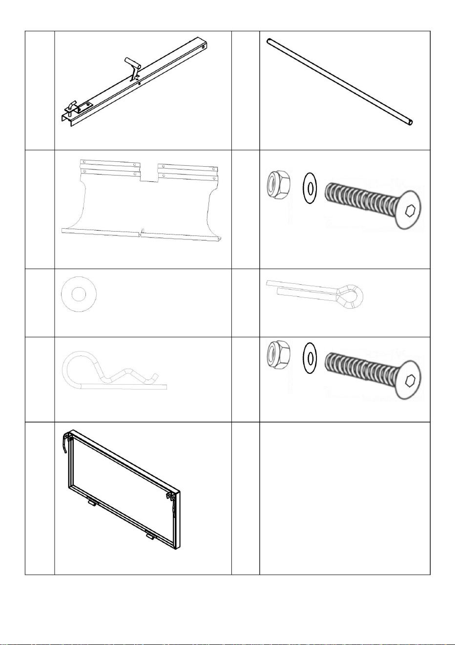
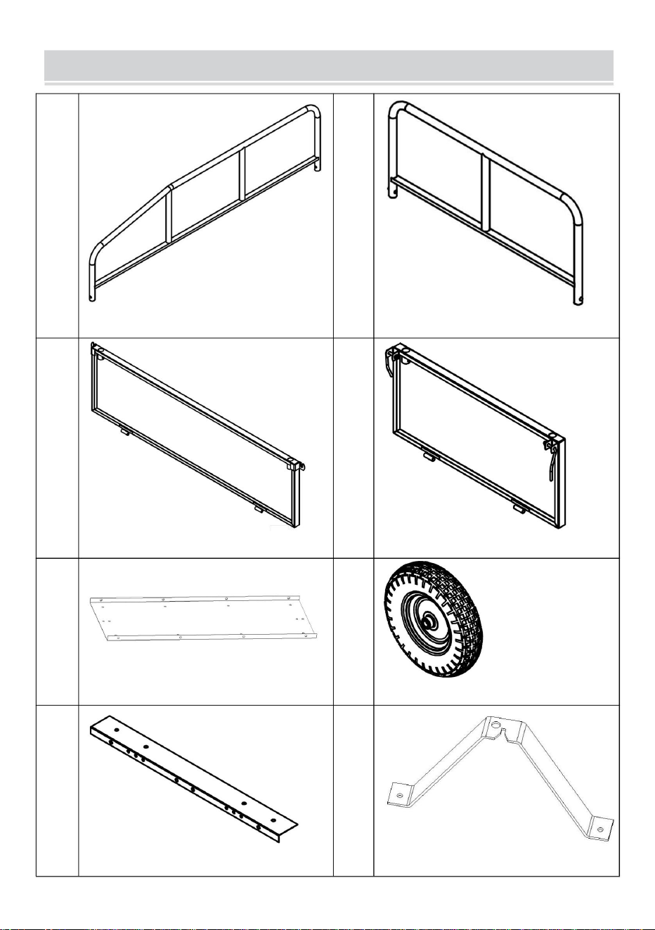
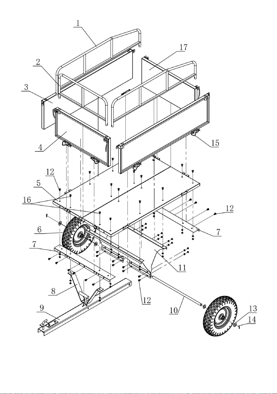
PARTS LIST
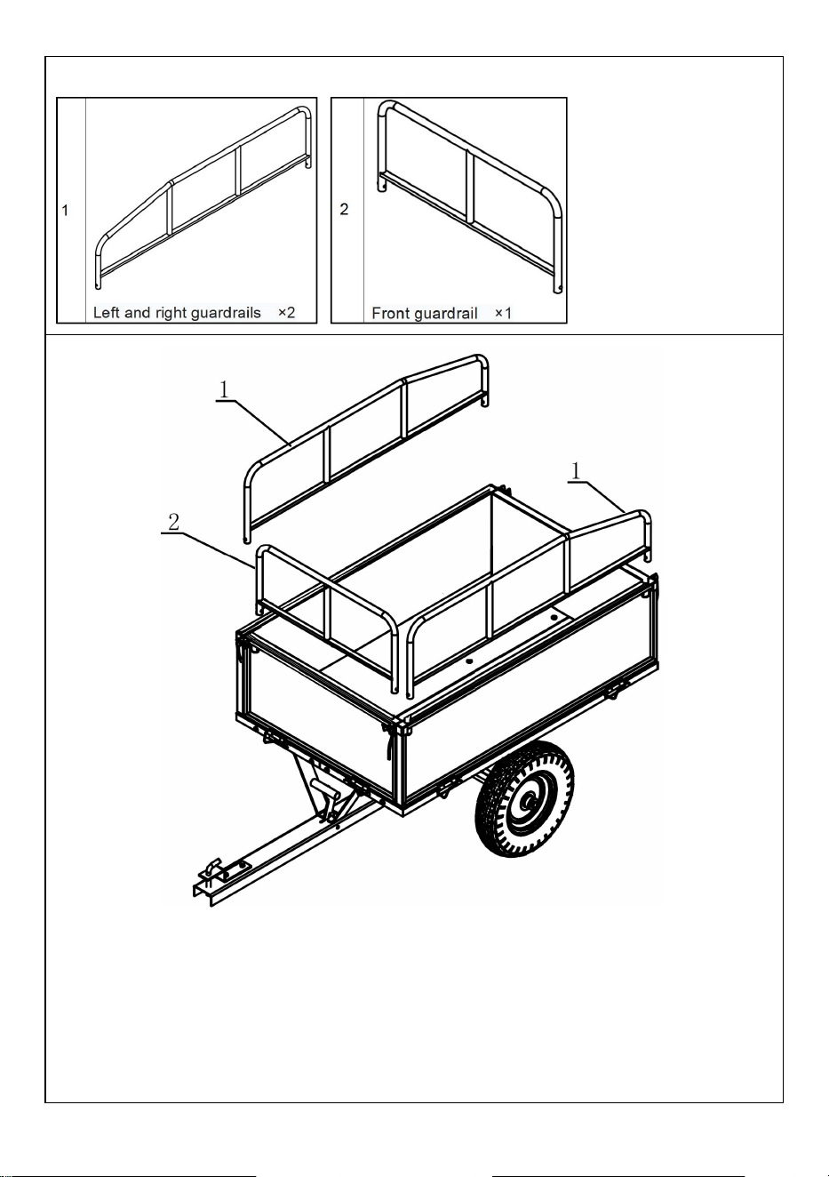
1
Left and right guardrails ×2
2
Front guardrail ×1
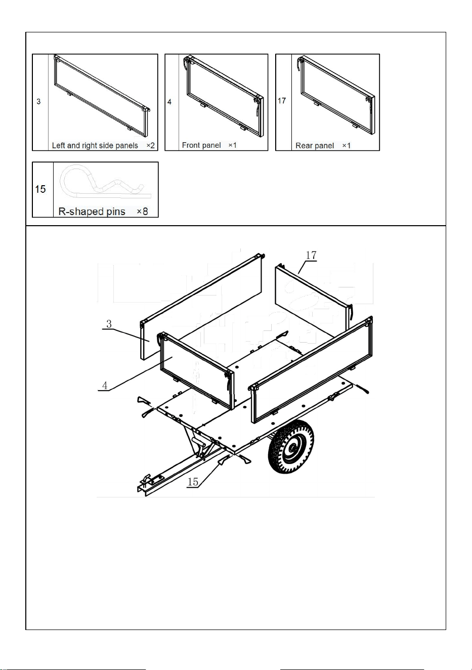
3
Left and right side panels ×2
4
Front panel ×1
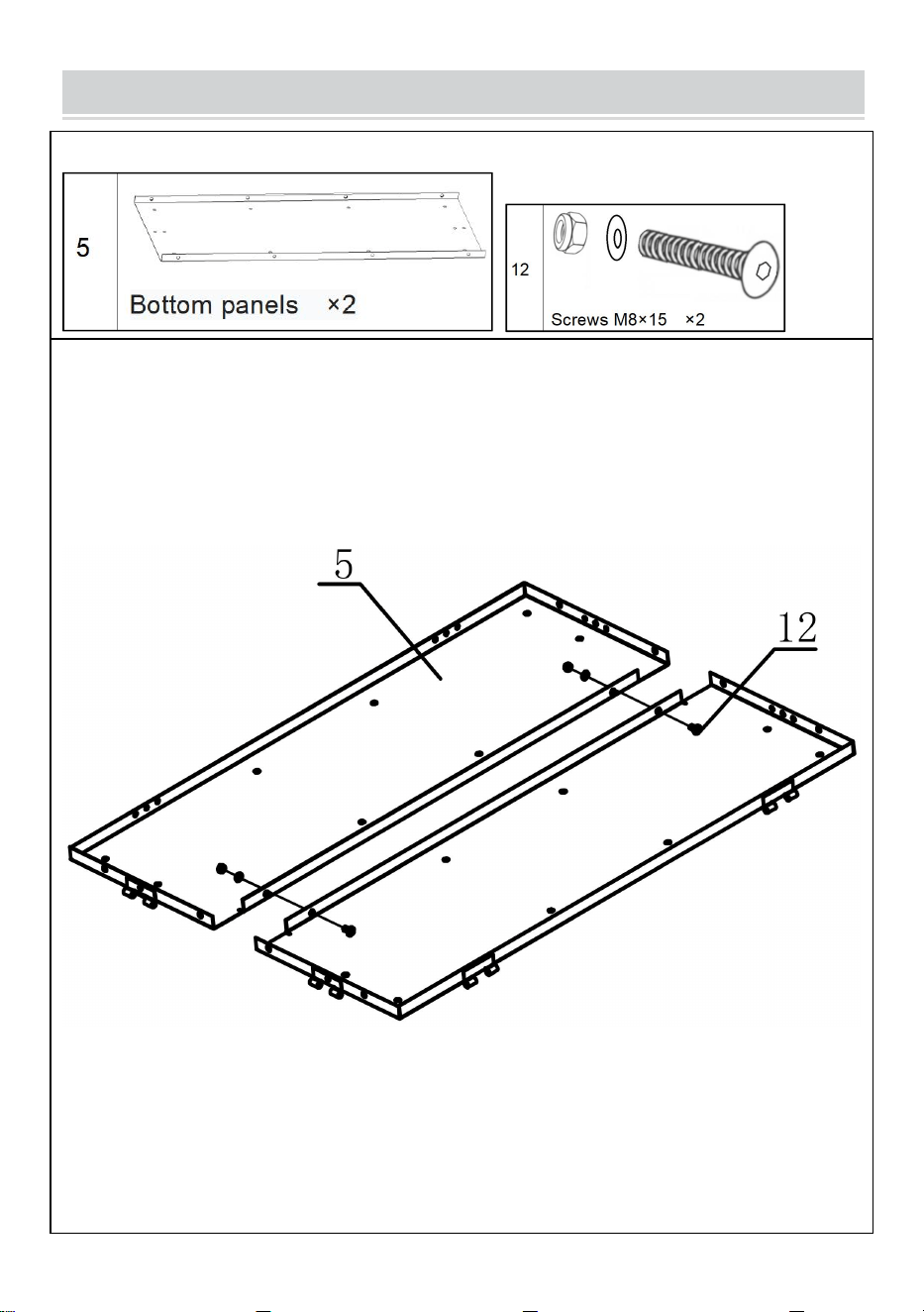
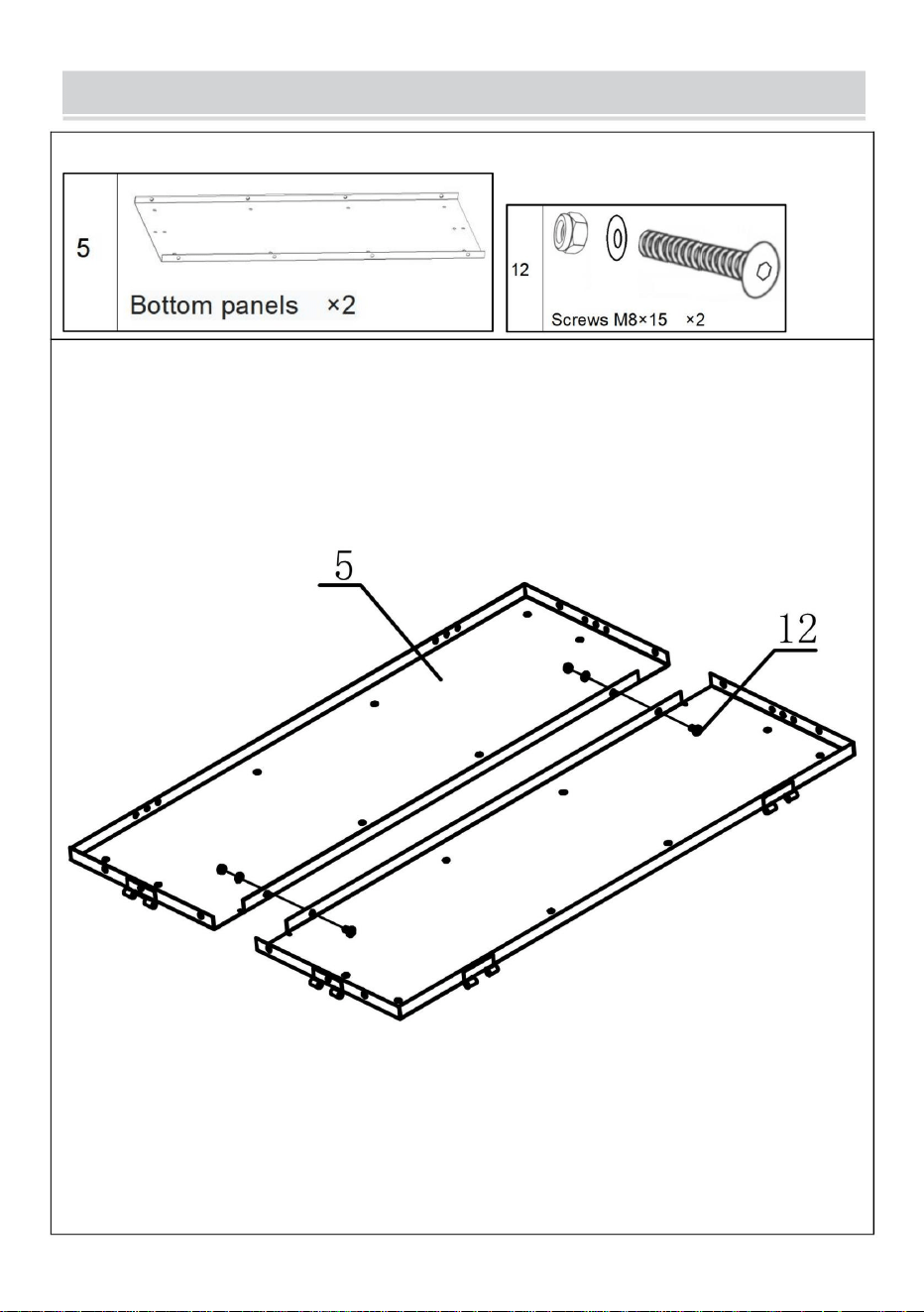
5
Bottom panels ×2
6
Tires ×2
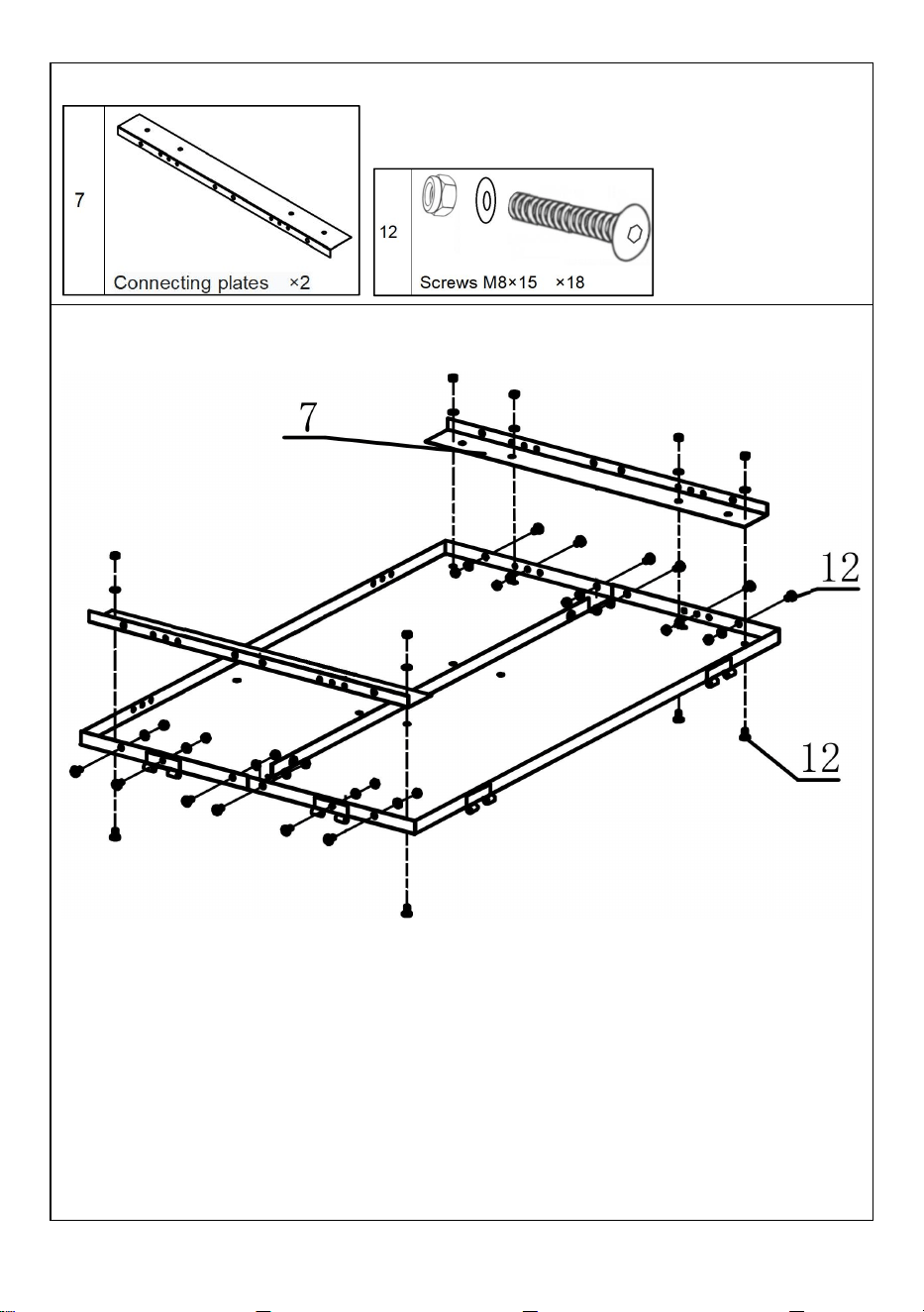
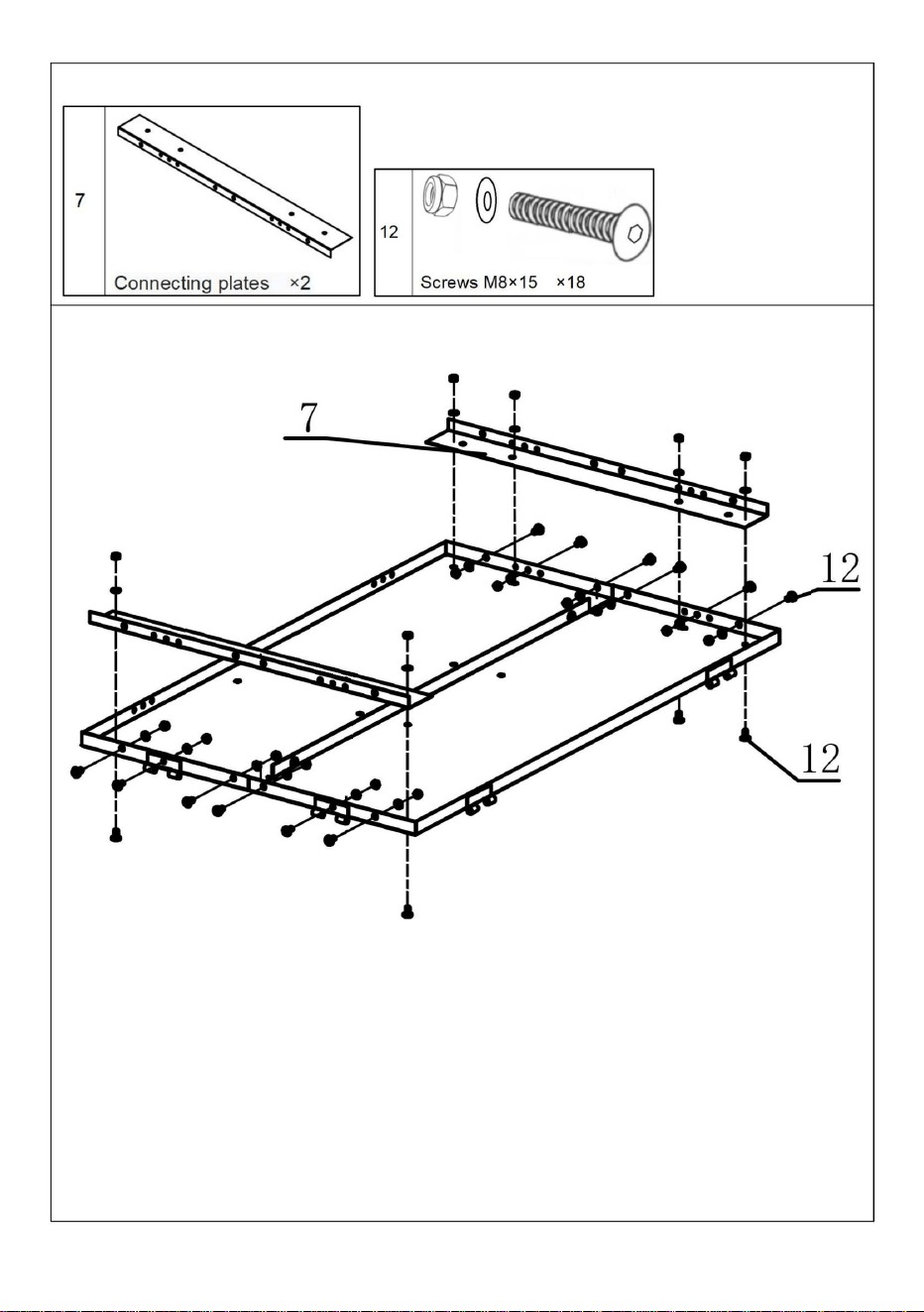
7
Connecting plates ×2
8
Support piece ×1
- 4 -
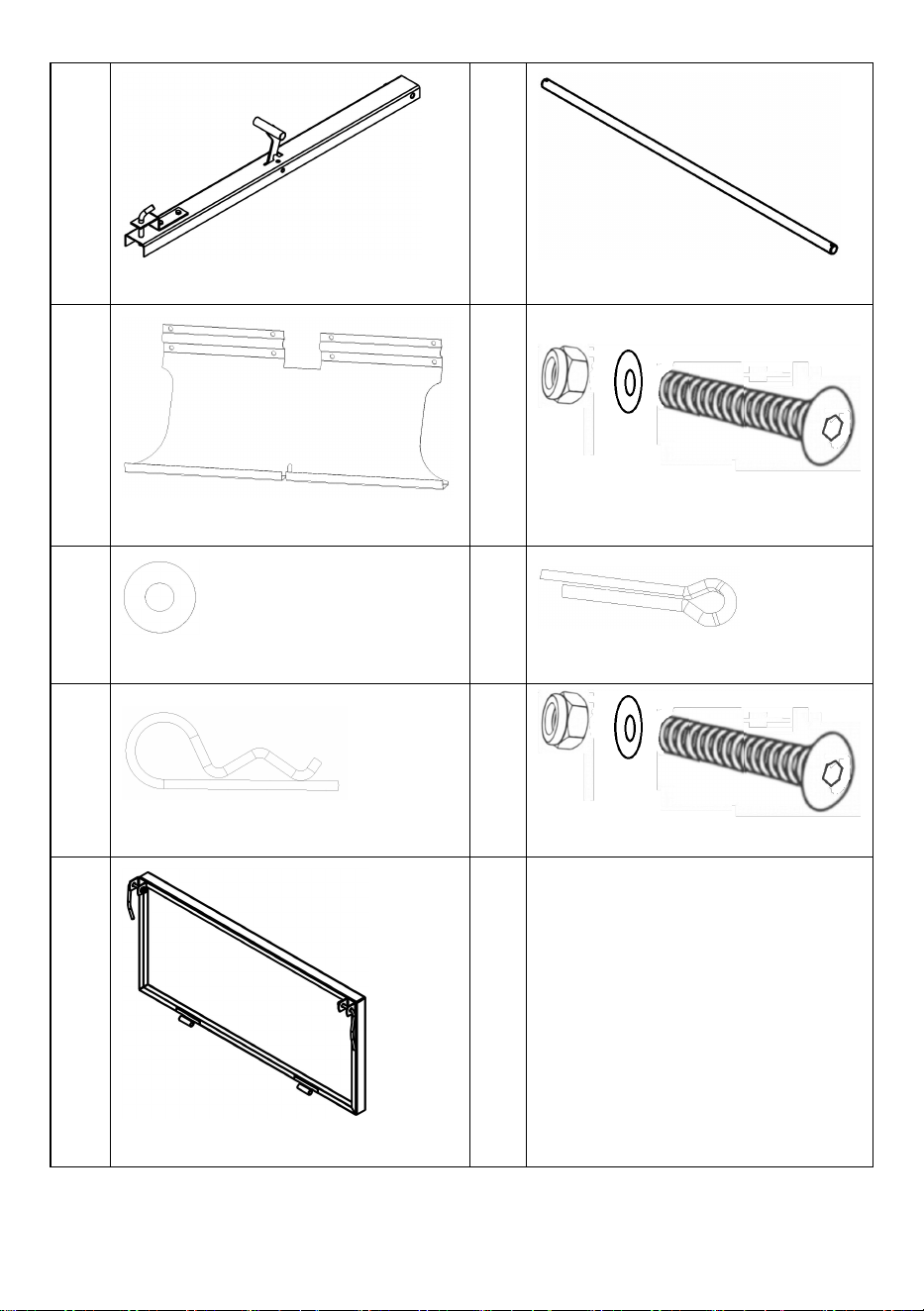
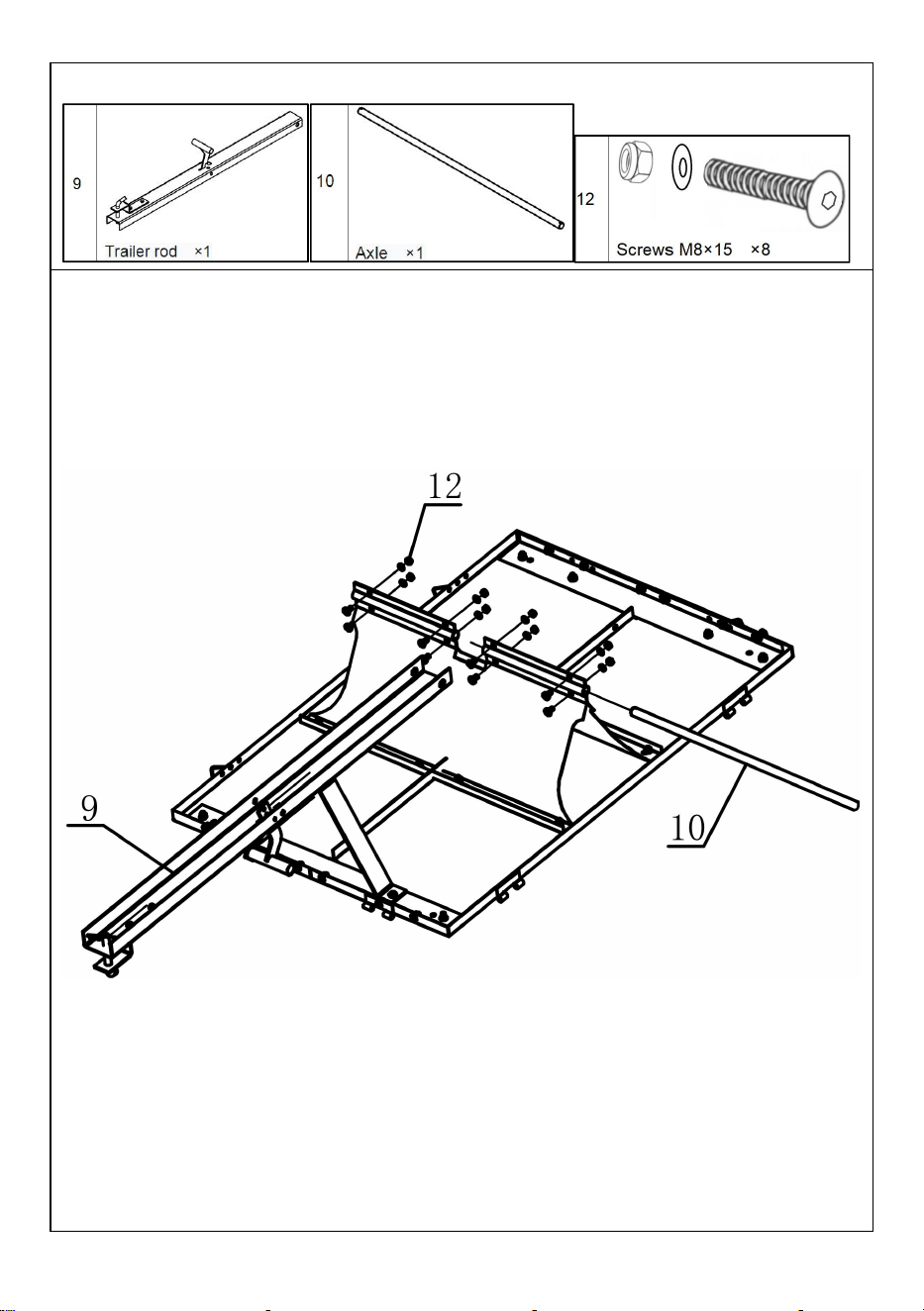
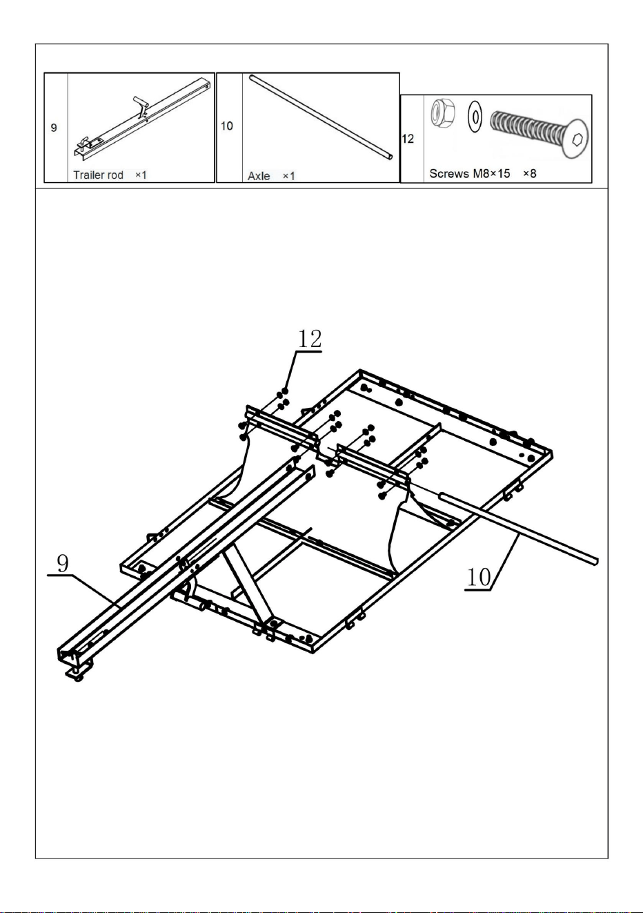
9
Trailer rod ×1
10
Axle ×1
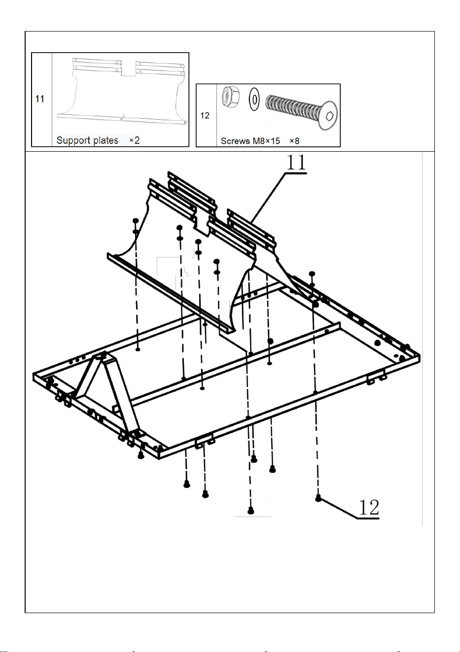
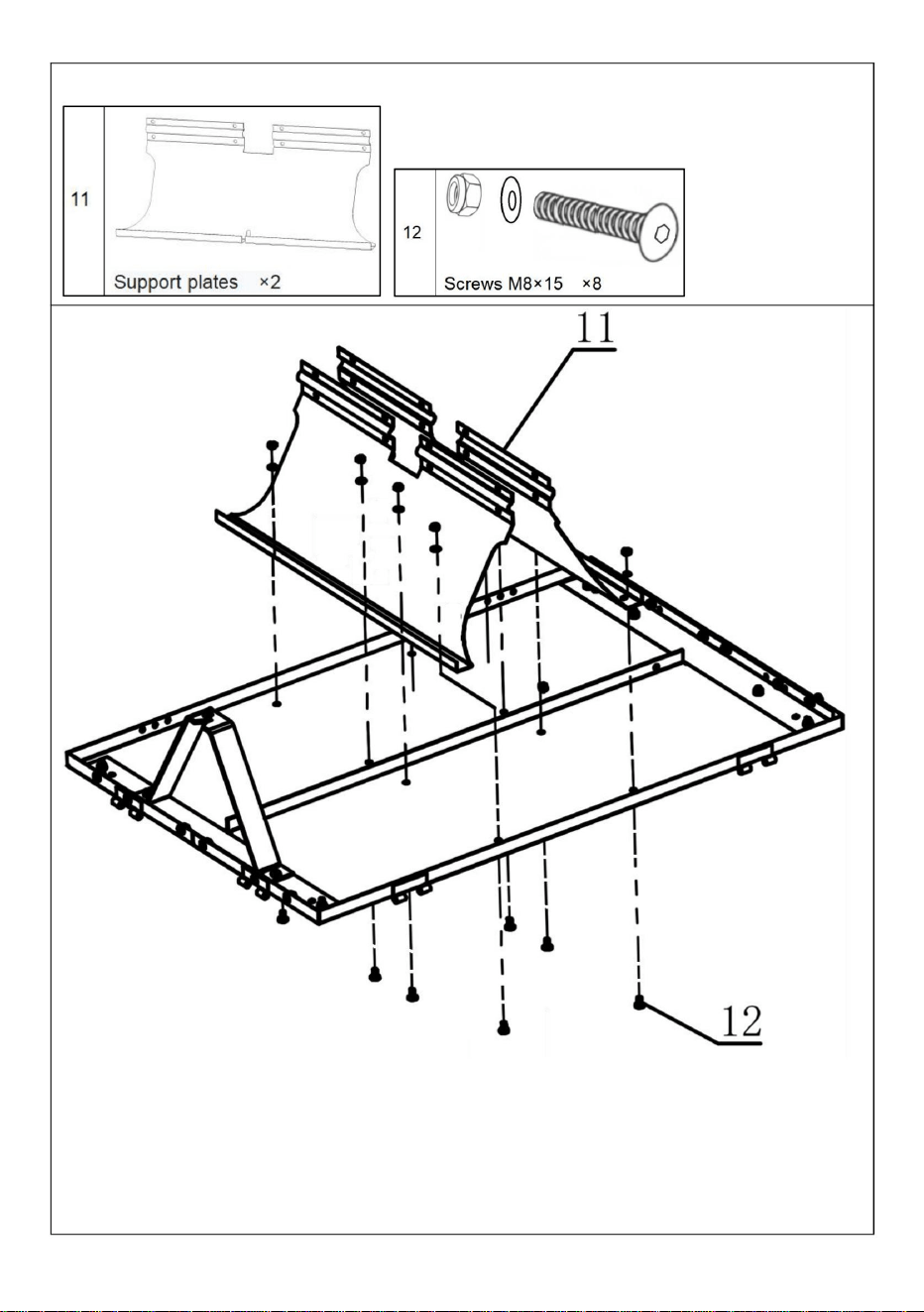
11
Support plates ×2
12
Screws M8×15 ×36
13
Large washers ×4
14
Pins ×2
15
R-shaped pins ×8
16
Screws M8×20 ×2
17
Rear panel ×1
- 5 -
- 6 -
ASSEMBLY STEP
STEP 1
1. Place the two bottom panels(No.5 x2) on a flat installation surface in the correct
orientation.
2. Screw the M8×15(No.12 x2) screws into the corresponding mounting holes on
the bottom panels(No.5 x2) respectively.
- 7 -
STEP 2
1. Align the connecting plate
(No.7 x2)
with the pre - reserved connection
position on the bottom panel
(No.5)
. The installation holes of the connecting
plate should be precisely aligned with those on the bottom panel.
2. Sequentially screw M8×15
(No.12 x18)
screws into the corresponding
installation holes of the connecting plate and the bottom panel, and then
tighten them.
3. Pay attention to the installation direction of the connecting plate.

- 8 -
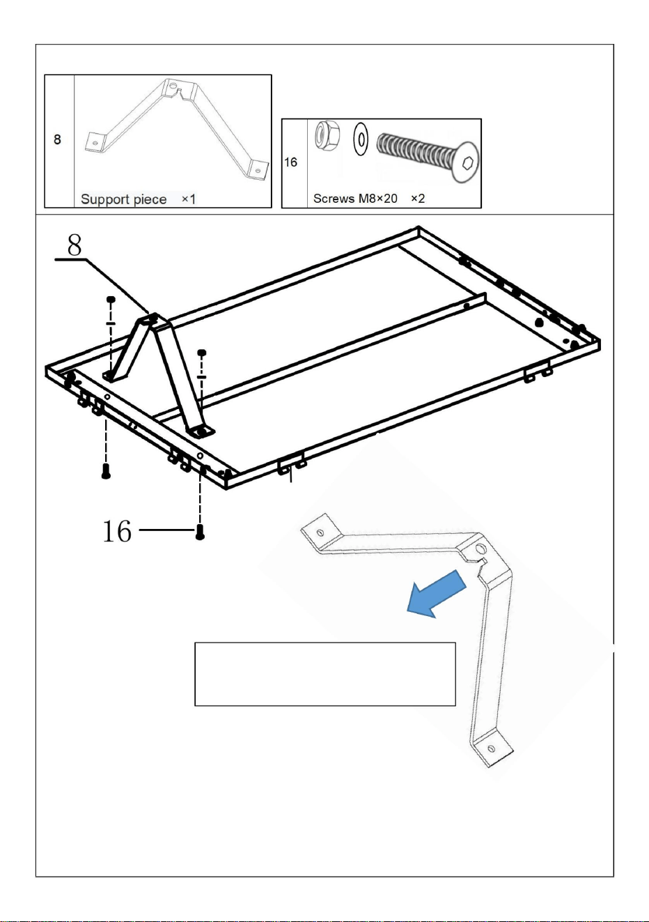
STEP 3
1. After placing the support piece(No.8 x1) in position, use M8×20
screws(No.16 x2) to fix it.
The opening of the support
piece should face outwards.
- 9 -
STEP 4
1. Install the two support plates(No.11 x2) at the specified positions
respectively.
2. Fix the bottoms of the support plates(No.11 x2) to the bottom panels with
M8×15 screws(No.12 x12).
3. Fix the two support plates with 4 M8×15 screws.
- 10 -
STEP 5
1. Place the trailer rod(No.9) in the middle position of the support
plates(No.11).
2. Insert the axle(No.10) between the support plates and make it pass
through the trailer rod.
3. Use M8×15 screws(No.12 x8) to firmly fix the support plates.

- 11 -
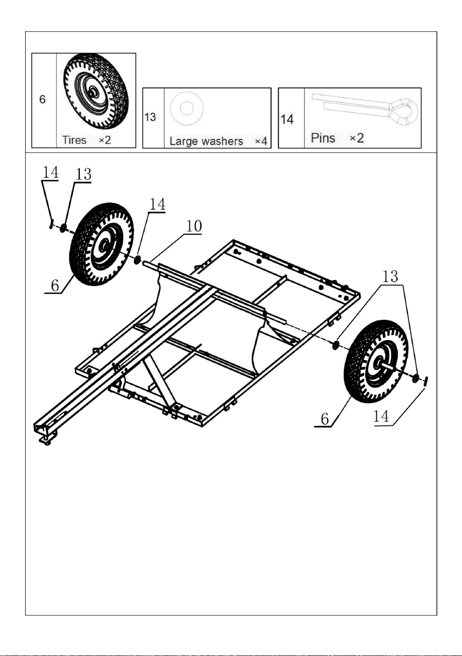
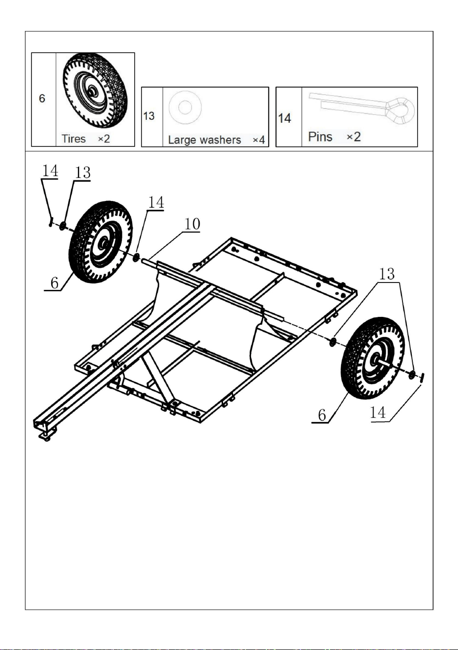
STEP 5
1. Put one washer(No.13 x2) on each side of the axle of the wheel shaft.
2. Install the wheels(No.6 x2) (with the inflation port facing outwards) onto
the axle.
3. Put another washer(No.13 x2) on each side of the axle of the wheels.
4. Insert pins(No.14 x2) into the end holes of the axle of the wheel shaft
bracket to fix the wheels.
- 12 -
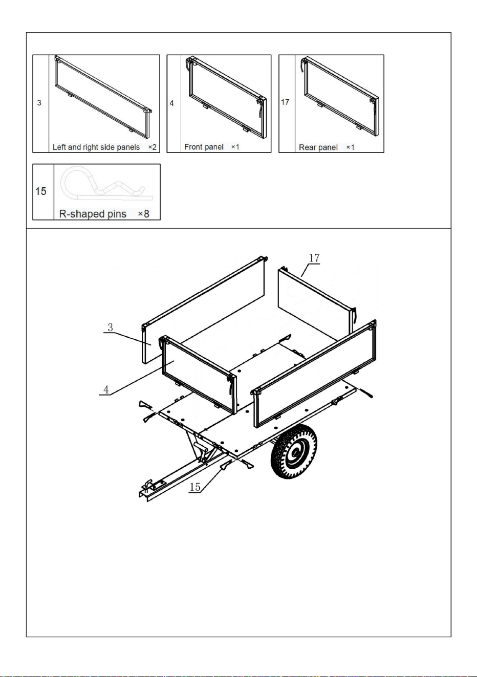
STEP 6
1. Install the left and right side panels(No.3 x2) on both sides of the trailer
respectively. Fix them with R-shaped pins(No.15), and pay attention to the
direction of the side panels.
2. Install the front panel(No.14) and fix it with R-shaped pins(No.15) .
3. Insert the rear panel(No.17) .
4. Fix the front and rear panels to the left and right side panels with the
quick pins by the front and rear panels.
- 13 -
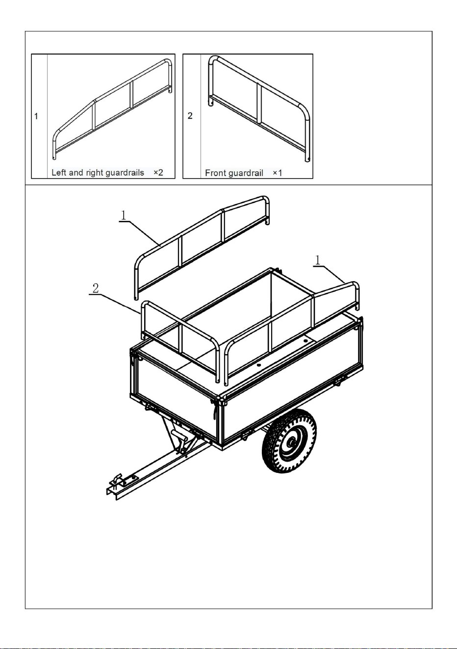
STEP 7
1. Insert the left and right guardrails(No.1 x2) into the holes of the trailer's
side panels respectively.
2. Insert the front guardrail(No.2) into the holes of the trailer's front panel
respectively.
- 14 -
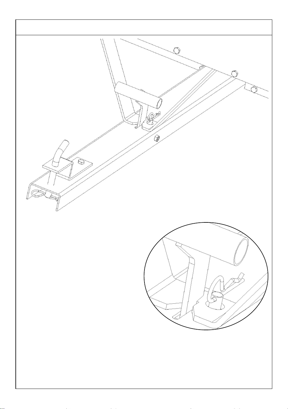
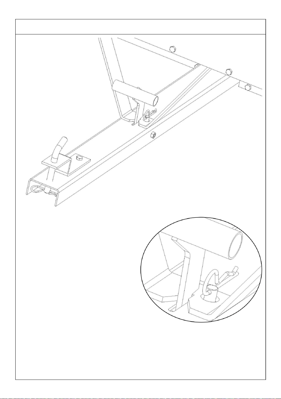
STEP 8
Pull out the cotter pin and lower the support.
Note: The cotter pin can be inserted or not.
If the tipping bucket is frequently used, there is no need to insert it.
When transporting for an extended period of time, please insert the
cotter pin to prevent the buckle from loosening due to jolting.
- 15 -
It is assembled and completed.

- 16 -
PRODUCT PARAMETER
Model
BTC002D
Volume
10 cu.ft
Carriage size
990*760*420mm
40*29.5*16.5inch
Maximum loading capacity
500 LBS
Model
BTC002E
Volume
17cu.ft
Carriage size
1070*760*585mm
42.1*30*23inch
Maximum loading capacity
600 LBS
Manufacturer: Shanghaimuxinmuyeyouxiangongsi
Address: Shuangchenglu 803nong11hao1602A-1609shi, baoshanqu,
shanghai 200000 CN.
Imported to AUS: SIHAO PTY LTD. 1 ROKEVA STREETEASTWOOD
NSW 2122 Australia
Imported to USA: Sanven Technology Ltd. Suite 250, 9166 Anaheim
Place, Rancho Cucamonga, CA 91730
REP
UK
YH CONSULTING LIMITED. C/O YH Consulting
Limited Office 147, Centurion House, London
Road, Staines-upon-Thames, Surrey, TW18 4AX
REP
EC
E-CrossStu GmbH
Mainzer Landstr.69,
60329 Frankfurt am Main.


MODEL: BTC002D/BTC002E
PRZYCZEPY OGRODOWE
Machine Translated by Google

Machine Translated by Google

To jest oryginalna instrukcja, przed użyciem należy uważnie przeczytać wszystkie
instrukcje. VEVOR zastrzega sobie jasną interpretację naszej instrukcji obsługi.
Wygląd produktu będzie zależał od produktu, który otrzymałeś. Prosimy o
wybaczenie, że nie poinformujemy Cię ponownie, jeśli w naszym produkcie pojawią
się jakiekolwiek aktualizacje technologiczne lub oprogramowania.
MODEL: BTC002D/BTC002E
PRZYCZEPY OGRODOWE
- 1 -
Machine Translated by Google

spowodować poważne obrażenia.
lub leków.
3. Utrzymuj miejsce zgromadzenia w czystości i zapewnij dobre oświetlenie.
w trakcie montażu.
7. Aby uzyskać dodatkowe informacje dotyczące części wymienionych poniżej,
strony, zapoznaj się ze schematem montażu w tym podręczniku. Rozpakuj
OSTRZEŻENIE:
4. Podczas montażu nie dopuszczaj osób postronnych na teren montażu.
stwarzać zagrożenia.
Montaż należy wykonać na płaskiej, równej, twardej i gładkiej powierzchni, która zapewni bezpieczeństwo.
i oddziel wszystkie części w czystym miejscu pracy.
3. Nie przekraczać określonego limitu obciążenia.
wspieranie Garden Trailers
2. Noś okulary ochronne zatwierdzone przez ANSI i wytrzymałe rękawice robocze.
4. Używać wyłącznie zgodnie z przeznaczeniem.
5. Przed każdym użyciem należy przeprowadzić kontrolę. Nie należy używać produktu, jeśli jakieś części są luźne lub uszkodzone.
Środki ostrożności podczas montażu
ZAPISZ TĘ INSTRUKCJĘ
6. Możliwości produktu dotyczą prawidłowego i kompletnego montażu.
1. Montaż należy wykonywać wyłącznie zgodnie z niniejszą instrukcją. Nieprawidłowy montaż może
tylko produkty.
2. Ten produkt nie jest zabawką. Nie pozwalaj dzieciom bawić się nim ani przebywać w jego pobliżu.
przedmiot.
5. Nie wchodź na zebranie, jeśli jesteś zmęczony lub znajdujesz się pod wpływem alkoholu, narkotyków lub narkotyków.
Przeczytaj ten materiał przed użyciem tego produktu. Nieprzestrzeganie tego może
Stosuj środki ostrożności
1. NIE SIADAJ ANI NIE STAWAJ NA TYM PRZEDMIOCIE.
INSTRUKCJE BEZPIECZEŃSTWA
- 2 -
Machine Translated by Google

Poręcze lewe i prawe ×2
Panel przedni ×1
Opony ×2
5 6
1
4
Płyty łączące ×2
Element podporowy ×1
Lewy i prawy panel boczny ×2
Barierka przednia ×1
7
3
8
Panele dolne ×2
2
LISTA CZĘŚCI
- 3 -
Machine Translated by Google

- 4 -
15
13
Panel tylny ×1
9
14
10
Szpilki ×2
Śruby M8×15×36
Śruby M8×20 ×2
Płyty podporowe ×2
17
11
16
12
Kołki w kształcie litery R ×8
Pręt przyczepy ×1
Duże podkładki ×4
Oś ×1
Machine Translated by Google

- 5 -
Machine Translated by Google

orientacja.
1. Umieść dwa dolne panele (nr 5 x 2) na płaskiej powierzchni montażowej w odpowiednim miejscu.
2. Wkręć śruby M8×15 (nr 12 x 2) w odpowiednie otwory montażowe na dolnych panelach (nr 5 x 2).
KROK 1
KROK MONTAŻU
- 6 -
Machine Translated by Google

- 7 -
otwory montażowe płyty łączącej i panelu dolnego, a następnie
dokręć je.
2. Kolejno wkręć śruby M8×15 (nr 12 x 18) w odpowiednie otwory.
położenie na dolnym panelu (nr 5). Otwory montażowe łączące
Płyta powinna być dokładnie wyrównana z tymi na dolnym panelu.
1. Wyrównaj płytkę łączącą (nr 7 x 2) z wcześniej zarezerwowanym połączeniem
KROK 2
3. Należy zwrócić uwagę na kierunek montażu płytki łączącej.
Machine Translated by Google
- 8 -
1. Po umieszczeniu elementu podporowego (nr 8 x 1) na miejscu, należy użyć śrub M8×20
(nr 16 x 2), aby go przymocować.
KROK 3
Otwór w elemencie podporowym
powinien być skierowany na zewnątrz.
Machine Translated by Google

- 9 -
1. Zamontuj dwie płyty podporowe (nr 11 x 2) w określonych pozycjach.
2. Przymocuj dolne części płyt podporowych (nr 11 x 2) do dolnych paneli za pomocą
odpowiednio.
KROK 4
3. Przymocuj dwie płyty podporowe za pomocą 4 śrub M8×15.
Śruby M8×15 (nr 12 x 12).
Machine Translated by Google

- 10 -
2. Włóż oś (nr 10) pomiędzy płyty podporowe i przełóż ją
1. Umieść drążek przyczepy (nr 9) w środkowej pozycji podpory
KROK 5
3. Za pomocą śrub M8×15 (nr 12 x 8) mocno zamocuj płyty podporowe.
przez drążek przyczepy.
talerze (nr 11).
Machine Translated by Google
- 11 -
2. Zamontuj koła (nr 6 x 2) (z portem do pompowania skierowanym na zewnątrz) na
oś.
1. Załóż po jednej podkładce (nr 13 x 2) po każdej stronie osi wału koła.
KROK 5
4. Włóż kołki (nr 14 x 2) do otworów końcowych osi wału koła
uchwyt do mocowania kół.
3. Załóż kolejną podkładkę (nr 13 x 2) po każdej stronie osi kół.
Machine Translated by Google

- 12 -
3. Włóż tylny panel (nr 17) .
4. Przymocuj panel przedni i tylny do panelu bocznego lewego i prawego za pomocą
2. Zamontuj panel przedni (nr 14) i zamocuj go za pomocą kołków w kształcie litery R (nr 15) .
szybkie szpilki przy przednim i tylnym panelu.
odpowiednio. Zamocuj je za pomocą kołków w kształcie litery R (nr 15) i zwróć uwagę na
kierunek paneli bocznych.
1. Zamontuj lewy i prawy panel boczny (nr 3 x 2) po obu stronach przyczepy.
KROK 6
Machine Translated by Google

- 13 -
1. Włóż lewą i prawą barierkę ochronną (nr 1 x 2) odpowiednio do otworów w
bocznych panelach przyczepy.
KROK 7
2. Włóż przednią barierkę ochronną (nr 2) odpowiednio do otworów w przednim
panelu przyczepy.
Machine Translated by Google

Uwaga: Zawleczkę można włożyć lub nie.
Jeżeli wiadro z funkcją przechylania jest często używane, nie ma potrzeby jego wkładania.
Wyciągnij zawleczkę i opuść podporę.
KROK 8
zawleczka zabezpieczająca klamrę przed poluzowaniem pod wpływem wstrząsów.
W przypadku transportu trwającego dłuższy czas, należy włożyć
- 14 -
Machine Translated by Google

Jest zmontowany i ukończony.
- 15 -
Machine Translated by Google

600 funtów
BTC002D
17 stóp sześciennych
BTC002E
Rozmiar powozu
Maksymalna ładowność
Model
Wymiary: 1070*760*585 mm
40*29,5*16,5 cala
Model
Tom
500 funtów
10 stóp sześciennych
Rozmiar powozu
990*760*420 mm
Maksymalna ładowność
42,1*30*23 cale
Tom
REP WIELKIEJ BRYTANII
Przedstawiciel UE
YH CONSULTING LIMITED. C/O YH Consulting
NSW 2122 Australia
Miejsce, Rancho Cucamonga, CA 91730
Biuro Limited 147, Centurion House, Londyn
Importowane do AUS: SIHAO PTY LTD. 1 ROKEVA STREETEASTWOOD
Importowane do USA: Sanven Technology Ltd. Suite 250, 9166 Anaheim
Adres: Shuangchenglu 803nong11hao1602A-1609shi, baoshanqu, szanghaj
200000 CN.
Producent: Shanghaimuxinmuyeyouxiangongsi
E-CrossStu GmbH
Droga, Staines-upon-Thames, Surrey, TW18 4AX
Mainzer Landstr.69,
60329 Frankfurt nad Menem.
PARAMETR PRODUKTU
- 16 -
Machine Translated by Google

Machine Translated by Google

Machine Translated by Google

RIMORCHI DA GIARDINO
MODELLO: BTC002D/BTC002E
Machine Translated by Google

Machine Translated by Google

- 1 -
RIMORCHI DA GIARDINO
Questa è l'istruzione originale, si prega di leggere attentamente tutte le istruzioni
del manuale prima di utilizzare. VEVOR si riserva una chiara interpretazione
del nostro manuale utente. L'aspetto del prodotto sarà soggetto al prodotto
ricevuto. Vi preghiamo di perdonarci se non vi informeremo di nuovo se ci sono
aggiornamenti tecnologici o software sul nostro prodotto.
MODELLO: BTC002D/BTC002E
Machine Translated by Google

- 2 -
ISTRUZIONI DI SICUREZZA
Precauzioni di montaggio
2. Indossare occhiali di sicurezza approvati ANSI e guanti da lavoro resistenti
sostenere i Garden Trailers
4. Utilizzare solo come previsto.
creare pericoli.
Montare su una superficie piana, livellata, dura e liscia in grado di resistere in modo sicuro
AVVERTIMENTO:
4. Tenere gli astanti fuori dall'area durante l'assemblea.
pagine, fare riferimento allo schema di montaggio di questo manuale. Disimballare
e separare tutte le parti in un'area di lavoro pulita.
3. Mantenere l'area di assemblaggio pulita e ben illuminata.
durante l'assemblaggio.
7. Per ulteriori informazioni sulle parti elencate di seguito
o farmaci.
provocare lesioni gravi.
1. NON SEDERSI O STARE IN PIEDI SU QUESTO OGGETTO.
3. Non superare le capacità di peso specificate.
Leggere questo materiale prima di utilizzare questo prodotto. La mancata osservanza di questa norma può
5. Non riunirsi se si è stanchi o sotto l'effetto di alcol, droghe
Usare precauzioni
5. Ispezionare prima di ogni utilizzo; non utilizzare se alcune parti sono allentate o danneggiate.
articolo.
SALVA QUESTO MANUALE
1. Montare solo secondo queste istruzioni. Un montaggio improprio può
6. Le capacità del prodotto si applicano a prodotti correttamente e completamente assemblati
solo prodotti.
2. Questo prodotto non è un giocattolo. Non permettere ai bambini di giocare con o vicino a questo
Machine Translated by Google
- 3 -
ELENCO DELLE PARTI
Guardrail anteriore ×1
Pannelli laterali sinistro e destro ×2
Pezzo di supporto ×1
4
Piastre di collegamento ×2
1
65
Pannello frontale ×1
Guardrail sinistro e destro ×2
Pneumatici ×2
2
Pannelli inferiori ×2
3
7
8
Machine Translated by Google

11
Piastre di supporto ×2
17
Viti M8×15 ×36
Viti M8×20 ×2
10
Perni ×2
9
13
14
Asse ×1
15
Pannello posteriore ×1
Barra di traino ×1
Rondelle grandi ×4
12
16
Perni a forma di R ×8
- 4 -
Machine Translated by Google

- 5 -
Machine Translated by Google

orientamento.
1. Posizionare i due pannelli inferiori (n. 5 x 2) su una superficie di installazione piana nella posizione corretta
2. Avvitare le viti M8×15 (n. 12 x2) nei fori di montaggio corrispondenti sui pannelli inferiori (n. 5 x2)
rispettivamente.
- 6 -
PASSO 1
FASE DI MONTAGGIO
Machine Translated by Google

- 7 -
stringerli.
fori di installazione della piastra di collegamento e del pannello inferiore, quindi
la piastra deve essere allineata esattamente con quelle del pannello inferiore.
3. Prestare attenzione alla direzione di installazione della piastra di collegamento.
posizione sul pannello inferiore (n. 5). I fori di installazione del collegamento
2. Avvitare in sequenza le viti M8×15 (n. 12 x18) nei fori corrispondenti
1. Allineare la piastra di collegamento (n. 7 x 2) con la connessione pre-riservata
PASSO 2
Machine Translated by Google

L'apertura del pezzo di supporto
deve essere rivolta verso l'esterno.
1. Dopo aver posizionato il pezzo di supporto (n. 8 x 1) in posizione, utilizzare viti
M8×20 (n. 16 x 2) per fissarlo.
PASSO 3
- 8 -
Machine Translated by Google

- 9 -
1. Installare le due piastre di supporto (n. 11 x 2) nelle posizioni specificate
Viti M8×15 (n. 12 x12).
rispettivamente.
PASSO 4
3. Fissare le due piastre di supporto con 4 viti M8×15.
2. Fissare le parti inferiori delle piastre di supporto (n. 11 x 2) ai pannelli inferiori con
Machine Translated by Google

piatti(n.11).
2. Inserire l' asse (n. 10) tra le piastre di supporto e farlo passare
attraverso la barra del rimorchio.
1. Posizionare l' asta del rimorchio (n. 9) nella posizione centrale del supporto
PASSO 5
3. Utilizzare viti M8×15 (n. 12 x8) per fissare saldamente le piastre di supporto.
- 10 -
Machine Translated by Google

- 11 -
1. Posizionare una rondella (n. 13 x 2) su ciascun lato dell'asse del perno della ruota.
3. Mettere un'altra rondella (n. 13 x 2) su ciascun lato dell'asse delle ruote.
2. Installare le ruote (n. 6 x 2) (con la porta di gonfiaggio rivolta verso l'esterno) su
PASSO 5
staffa per fissare le ruote.
4. Inserire i perni (n. 14 x 2) nei fori terminali dell'asse del perno della ruota
l'asse.
Machine Translated by Google

- 12 -
4. Fissare i pannelli anteriore e posteriore ai pannelli laterali sinistro e destro con il
3. Inserire il pannello posteriore (n. 17) .
direzione dei pannelli laterali.
perni rapidi vicino ai pannelli anteriore e posteriore.
rispettivamente. Fissarli con perni a forma di R (n. 15) e prestare attenzione al
2. Installare il pannello frontale (n. 14) e fissarlo con i perni a forma di R (n. 15) .
1. Installare i pannelli laterali sinistro e destro (n. 3 x 2) su entrambi i lati del rimorchio
PASSO 6
Machine Translated by Google

- 13 -
2. Inserire il guardrail anteriore (n. 2) rispettivamente nei fori del pannello anteriore del
rimorchio.
PASSO 7
1. Inserire i guardrail sinistro e destro (n. 1 x 2) rispettivamente nei fori dei pannelli laterali
del rimorchio.
Machine Translated by Google

- 14 -
Estrarre la coppiglia e abbassare il supporto.
In caso di trasporto per un periodo di tempo prolungato, inserire il
Nota: la coppiglia può essere inserita o meno.
PASSO 8
coppiglia per evitare che la fibbia si allenti a causa degli scossoni.
Se il cassone ribaltabile viene utilizzato frequentemente, non è necessario inserirlo.
Machine Translated by Google
- 15 -
È assemblato e completato.
Machine Translated by Google

Luogo, Rancho Cucamonga, CA 91730
YH CONSULTING LIMITED. Per conto di YH Consulting
Importato negli USA: Sanven Technology Ltd. Suite 250, 9166 Anaheim
Ufficio limitato 147, Centurion House, Londra
Importato in AUS: SIHAO PTY LTD. 1 ROKEVA STREETEASTWOOD
Nuovo Galles del Sud 2122 Australia
Indirizzo: Shuangchenglu 803nong11hao1602A-1609shi, baoshanqu, shanghai
200000 CN.
Produttore: Shanghaimuxinmuyeyouxiangongsi
E-CrossStu GmbH
Strada, Staines-upon-Thames, Surrey, TW18 4AX
Mainzer Landstr.69,
60329 Francoforte sul Meno.
Rappresentante della CE
RAPPRESENTANZA DEL REGNO UNITO
10 piedi cubi
500 libbre
Volume
40*29.5*16.5 pollici
Modello
Modello
1070*760*585mm
Capacità di carico massima
17 piedi cubi
Codice articolo: BTC002E
Dimensioni della carrozza
600 libbre
Codice articolo: BTC002D
Volume
42,1*30*23 pollici
990*760*420mm
Capacità di carico massima
Dimensioni della carrozza
PARAMETRO PRODOTTO
- 16 -
Machine Translated by Google

Machine Translated by Google

Machine Translated by Google

MODELO:BTC002D/BTC002E
REMOLQUESDEJARDÍN
Machine Translated by Google

Machine Translated by Google

Estassonlasinstruccionesoriginales;leaatentamentetodaslasinstruccionesdel
manualantesdeutilizarlo.VEVORsereservaelderechodeinterpretarsu
manualdeusuario.Laaparienciadelproductodependerádelproductoquehaya
recibido.Lerogamosquenosdisculpesinoleinformamosdenuevosihay
actualizacionestecnológicasodesoftwareennuestroproducto.
MODELO:BTC002D/BTC002E
REMOLQUESDEJARDÍN
1
Machine Translated by Google

Precaucionesdemontaje
2.UsegafasdeseguridadaprobadasporANSIyguantesdetrabajoresistentes.
ApoyandoalosGardenTrailers
4.Úseloúnicamentesegúnloprevisto.
crearpeligros.
Montarsobreunasuperficieplana,nivelada,duraylisacapazdesoportarcondicionesdeseguridad.
ADVERTENCIA:
4.Mantengaalostranseúntesfueradeláreaduranteelmontaje.
páginas,consulteeldiagramademontajedeestemanual.Desenvuelva
yseparetodaslaspiezasenunáreadetrabajolimpia.
3.Mantengaeláreademontajelimpiaybieniluminada.
Duranteelmontaje.
7.Paraobtenerinformaciónadicionalsobrelaspiezasenumeradasacontinuación,
provocarlesionesgraves.
omedicación.
1.NOSESIENTANISEPARESOBREESTEARTÍCULO.
3.Noexcedalascapacidadesdepesoespecificadas.
Leaestematerialantesdeusaresteproducto.Delocontrario,puede...
5.Nosereúnasiestácansadoobajolainfluenciadelalcoholodrogas.
Precaucionesdeuso
5.Inspeccioneantesdecadauso;noloutilicesilaspiezasestánsueltasodañadas.
artículo.
GUARDEESTEMANUAL
1.Ensambleúnicamentedeacuerdoconestasinstrucciones.Unmontajeincorrectopuede...
6.Lascapacidadesdelproductoseaplicanaproductosensambladoscorrectamenteycompletamente.
Sóloproductos.
2.Esteproductonoesunjuguete.Nopermitaquelosniñosjueguenconélnicercadeél.
INSTRUCCIONESDESEGURIDAD
2
Machine Translated by Google

Piezadesoporte×1
Paneleslateralesizquierdoyderecho×2
4
Placasdeconexión×2
1
65
Panelfrontal×1
Neumáticos×2
Barandillasizquierdayderecha×2
Panelesinferiores×2
2
3
8
7
Barandilladelantera×1
LISTADEPIEZAS
3
Machine Translated by Google
4
17
Placasdesoporte×2
TornillosM8×15×36
TornillosM8×20×2
10
Pines×2
9
14
13
Paneltrasero×1
Eje×1
15
Arandelasgrandes×4
Varilladeremolque×1
12
PasadoresenformadeR×8
16
11
Machine Translated by Google

5
Machine Translated by Google

orientación.
1.Coloquelosdospanelesinferiores(n.°5x2)sobreunasuperficiedeinstalaciónplanaenladireccióncorrecta.
2.AtornillelostornillosM8×15(n.°12x2)enlosorificiosdemontajecorrespondientesenlospanelesinferiores
(n.°5x2)respectivamente.
6
PASO1
PASODEMONTAJE
Machine Translated by Google

7
2.AtornillesecuencialmentelostornillosM8×15(n.°12x18)enlossoportescorrespondientes.
agujerosdeinstalacióndelaplacadeconexiónyelpanelinferior,yluego
apriételos.
Posiciónenelpanelinferior(n.°5).Losorificiosdeinstalacióndelaconexión...
Laplacadebeestaralineadaconprecisiónconlasdelpanelinferior.
1.Alineelaplacadeconexión(n.°7x2)conlaconexiónreservadapreviamente.
PASO2
3.Presteatenciónaladireccióndeinstalacióndelaplacadeconexión.
Machine Translated by Google

8
1.Despuésdecolocarlapiezadesoporte(n.°8x1)ensuposición,utilicetornillos
M8×20(n.°16x2)parafijarla.
PASO3
Laaperturadelapiezade
soportedebemirarhaciaafuera.
Machine Translated by Google

respectivamente.
2.Fijelaspartesinferioresdelasplacasdesoporte(n.°11x2)alospanelesinferiorescon
1.Instalelasdosplacasdesoporte(n.°11x2)enlasposicionesespecificadas
PASO4
TornillosM8×15(n.°12x12).
3.Fijelasdosplacasdesoportecon4tornillosM8×15.
9
Machine Translated by Google

placas(No.11).
1.Coloquelabarradelremolque(n.°9)enlaposiciónmediadelsoporte.
atravésdelabarradelremolque.
2.Inserteeleje(No.10)entrelasplacasdesoporteyhágalopasar
PASO5
3.UtilicetornillosM8×15(n.°12x8)parafijarfirmementelasplacasdesoporte.
10
Machine Translated by Google

11
2.Instalelasruedas(n.°6x2)(conelpuertodeinfladohaciaafuera)en
eleje.
1.Coloqueunaarandela(n.°13x2)encadaladodelejedelejedelarueda.
PASO5
3.Coloqueotraarandela(n.°13x2)encadaladodelejedelasruedas.
4.Insertepasadores(n.°14x2)enlosorificiosdelosextremosdelejedelejedelarueda.
Soporteparafijarlasruedas.
Machine Translated by Google

12
2.Instaleelpanelfrontal(n.°14)yfíjeloconpasadoresenformadeR(n.°15).
3.Inserteelpaneltrasero(n.°17).
4.Fijelospanelesfrontalytraseroalospaneleslateralesizquierdoyderechoconlos
respectivamente.FíjelosconpasadoresenformadeR(n.°15)ypresteatenciónala
Direccióndelospaneleslaterales.
1.Instalelospaneleslateralesizquierdoyderecho(n.°3x2)enambosladosdelremolque.
PASO6
Pasadoresrápidosjuntoalospanelesfrontalytrasero.
Machine Translated by Google

13
1.Insertelasbarandillasizquierdayderecha(n.°1x2)enlosorificiosdelospaneleslaterales
delremolquerespectivamente.
PASO7
2.Insertelabarandilladelantera(n.°2)enlosorificiosdelpanelfrontaldelremolque
respectivamente.
Machine Translated by Google

Saqueelpasadordechavetaybajeelsoporte.
Sielcucharónbasculanteseutilizaconfrecuencia,noesnecesarioinsertarlo.
Nota:Elpasadordechavetasepuedeinsertarono.
PASO8
Cuandolotransporteporunperíododetiempoprolongado,inserteel
Pasadordechavetaparaevitarquelahebillaseaflojedebidoalassacudidas.
14
Machine Translated by Google

Estamontadoyterminado.
15
Machine Translated by Google

ImportadoaEE.UU.:SanvenTechnologyLtd.Suite250,9166Anaheim
Lugar,RanchoCucamonga,CA91730
YHCONSULTINGLIMITADA.A/CYHConsulting
Oficinalimitada147,CenturionHouse,Londres
ImportadoaAUS:SIHAOPTYLTD.1ROKEVASTREET,EASTWOOD
NSW2122Australia
Dirección:Shuangchenglu803nong11hao1602A1609shi,baoshanqu,shanghai
200000CN.
Fabricante:Shanghaimuxinmuyeyouxiangongsi
ECrossStuGmbH
Carretera,StainesuponThames,Surrey,TW184AX
MainzerLandstr.69,
60329FráncfortdelMeno.
REPRESENTANTEDELREINOUNIDO
RepresentantedelaCE
Volumen
500libras
40x29,5x16,5pulgadas
Modelo
Modelo
1070*760*585mm
Capacidadmáximadecarga
17piescúbicos
BTC002E
Tamañodelcarro
BTC002D
600libras
42,1x30x23pulgadas
Volumen
990*760*420mm
Capacidadmáximadecarga
Tamañodelcarro
10piescúbicos
PARÁMETRODELPRODUCTO
16
Machine Translated by Google

Machine Translated by Google

Machine Translated by Google

MODELL: BTC002D/BTC002E
TRÄDGÅRDSSläpvagnar
Machine Translated by Google

Machine Translated by Google

Detta är den ursprungliga instruktionen, läs alla instruktioner noggrant innan
du använder den. VEVOR reserverar sig för en tydlig tolkning av vår
användarmanual. Utseendet på produkten är beroende av den produkt du
fått. Ursäkta oss att vi inte kommer att informera dig igen om det finns någon
teknik eller mjukvaruuppdateringar på vår produkt.
MODELL: BTC002D/BTC002E
TRÄDGÅRDSSläpvagnar
- 1 -
Machine Translated by Google

2. Bär ANSI-godkända skyddsglasögon och kraftiga arbetshandskar
stödja Garden Trailers
2. Denna produkt är inte en leksak. Låt inte barn leka med eller i närheten av detta
4. Använd endast på avsett sätt.
skapa faror.
Montera på en plan, jämn, hård och slät yta som kan säkert
3. Överskrid inte specificerade viktkapaciteter.
sidorna, se monteringsdiagrammet i denna manual. Packa upp
SPARA DENNA MANUAL
VARNING:
under monteringen.
4. Håll åskådare borta från området under monteringen.
7. För ytterligare information om delarna som listas nedan
3. Håll monteringsområdet rent och väl upplyst.
och separera alla delar i ett rent arbetsområde.
5. Inspektera före varje användning; Använd inte om delar är lösa eller skadade.
resultera i allvarlig skada.
eller medicinering.
1. SIT ELLER STÅ INTE PÅ DETTA FÖREMÅL.
Läs detta material innan du använder denna produkt. Underlåtenhet att göra det kan
5. Sätt dig inte ihop om du är trött eller påverkad av alkohol, droger
Använd försiktighetsåtgärder
1. Montera endast enligt dessa instruktioner. Felaktig montering kan
endast produkter.
punkt.
Försiktighetsåtgärder vid montering
6. Produktens egenskaper gäller för korrekt och fullständigt monterade
SÄKERHETSINSTRUKTIONER
- 2 -
Machine Translated by Google

Vänster och höger sidopaneler ×2
Stödstycke ×1
4
Anslutningsplåtar ×2
1
Frontpanel ×1
65
Vänster och höger skyddsräcken ×2
Däck ×2
2
Bottenpaneler ×2
3
8
Främre skyddsräcke ×1
7
DELLISTA
- 3 -
Machine Translated by Google

- 4 -
Stödplattor ×2
17
Skruvar M8×15 ×36
Skruvar M8×20 ×2
10
13
Pins ×2
Bakre panel ×1
9
14
Axel ×1
15
Släpvagnsstång ×1
Stora brickor ×4
12
R-formade stift ×8
11
16
Machine Translated by Google

- 5 -
Machine Translated by Google

2. Skruva fast M8×15(nr 12 x2) skruvarna i motsvarande monteringshål på bottenpanelerna (nr 5 x2).
1. Placera de två bottenpanelerna (nr 5 x2) på en plan installationsyta i rätt läge
orientering.
- 6 -
STEG 1
MONTERINGSTEG
Machine Translated by Google

- 7 -
plattan ska vara exakt i linje med dem på bottenpanelen.
2. Skruva sekventiellt M8×15(nr 12 x18) skruvar i motsvarande
dra åt dem.
position på bottenpanelen (nr 5). Installationshålen för anslutningen
installationshål för anslutningsplattan och bottenpanelen, och sedan
1. Rikta in anslutningsplattan (nr 7 x2) med den förbokade anslutningen
STEG 2
3. Var uppmärksam på monteringsriktningen för anslutningsplattan.
Machine Translated by Google

- 8 -
STEG 3
1. Efter att ha placerat stödstycket (nr 8 x1) på plats, använd M8×20-
skruvar (nr 16 x2) för att fixera det.
Stödstyckets öppning ska
vara vänd utåt.
Machine Translated by Google

- 9 -
respektive.
3. Fäst de två stödplattorna med 4 M8×15 skruvar.
1. Montera de två stödplattorna (nr 11 x2) på de angivna positionerna
STEG 4
2. Fäst botten av stödplattorna (nr. 11 x2) till bottenpanelerna med
M8×15 skruvar (nr 12 x12).
Machine Translated by Google

- 10 -
2. Sätt in axeln (nr 10) mellan stödplattorna och få den att passera
genom trailerstången.
1. Placera släpvagnsstången (nr 9) i mitten av stödet
STEG 5
3. Använd M8×15 skruvar (nr 12 x8) för att fästa stödplattorna ordentligt.
plattor (nr 11).
Machine Translated by Google

1. Sätt en bricka (nr 13 x 2) på varje sida av hjulaxelns axel.
4. Sätt in stift (nr 14 x2) i ändhålen på hjulaxelns axel
2. Montera hjulen (nr 6 x 2) (med uppblåsningsporten vänd utåt) på
STEG 5
axeln.
3. Sätt ytterligare en bricka (nr 13 x 2) på varje sida av hjulaxeln.
fäste för att fixera hjulen.
- 11 -
Machine Translated by Google
- 12 -
sidopanelernas riktning.
2. Montera frontpanelen (nr 14) och fixera den med R-formade stift (nr 15) .
4. Fäst de främre och bakre panelerna till vänster och höger sidopaneler med
respektive. Fixa dem med R-formade stift (nr 15), och var uppmärksam på
3. Sätt i den bakre panelen (nr 17) .
1. Installera vänster och höger sidopaneler (nr 3 x2) på båda sidor av släpvagnen
STEG 6
snabba stift vid fram- och bakpanelerna.
Machine Translated by Google
- 13 -
1. Sätt in vänster och höger skyddsräcken (nr 1 x 2) i hålen på släpvagnens
sidopaneler.
STEG 7
2. Sätt in det främre skyddsräcket (nr 2) i hålen på släpvagnens frontpanel.
Machine Translated by Google
- 14 -
Obs: Saxpinnen kan sättas in eller inte.
sax för att förhindra att spännet lossnar på grund av stötar.
Dra ut saxsprinten och sänk stödet.
STEG 8
Om tippskopan används ofta behöver du inte sätta in den.
Vid transport under en längre tid, vänligen sätt i
Machine Translated by Google

- 15 -
Den är monterad och färdig.
Machine Translated by Google

Importerad till USA: Sanven Technology Ltd. Suite 250, 9166 Anaheim
Place, Rancho Cucamonga, CA 91730
YH CONSULTING LIMITED. C/O YH Consulting
Limited Office 147, Centurion House, London
Adress: Shuangchenglu 803nong11hao1602A-1609shi, baoshanqu, shanghai
200000 CN.
NSW 2122 Australien
Importerad till AUS: SIHAO PTY LTD. 1 ROKEVA STREETEASTWOOD
Tillverkare: Shanghaimuxinmuyeyouxiangongsi
Road, Staines-upon-Thames, Surrey, TW18 4AX
Mainzer Landstr.69,
60329 Frankfurt am Main.
E-CrossStu GmbH
EC REP
UK REP
500 LBS
Volym
40*29,5*16,5 tum
Modell
Maximal lastkapacitet
Modell
BTC002E
1070*760*585mm
Vagnstorlek
17cu.ft
BTC002D
600 LBS
Volym
42,1*30*23tum
990*760*420mm
Maximal lastkapacitet
10 cu.ft
Vagnstorlek
PRODUKTPARAMETER
- 16 -
Machine Translated by Google

Machine Translated by Google

Machine Translated by Google

TUINWAGENS
MODEL: BTC002D/BTC002E
Machine Translated by Google

Machine Translated by Google
- 1 -
TUINWAGENS
Dit is de originele instructie, lees alle handleidingen zorgvuldig door voordat u het
product gebruikt. VEVOR behoudt zich een duidelijke interpretatie van onze
gebruikershandleiding voor. Het uiterlijk van het product is afhankelijk van het
product dat u hebt ontvangen. Vergeef ons dat we u niet opnieuw zullen informeren
als er technologie- of software-updates voor ons product zijn.
MODEL: BTC002D/BTC002E
Machine Translated by Google

- 2 -
VEILIGHEIDSINSTRUCTIES
Voorzorgsmaatregelen bij de montage
2. Draag een ANSI-goedgekeurde veiligheidsbril en stevige werkhandschoenen
ondersteuning van de Garden Trailers
4. Gebruik het product alleen zoals bedoeld.
gevaren creëren.
Monteer op een vlak, egaal, hard en glad oppervlak dat veilig kan worden gebruikt
WAARSCHUWING:
4. Houd omstanders uit de buurt tijdens de montage.
pagina's, raadpleeg dan het montageschema van deze handleiding. Uitpakken
en scheid alle onderdelen in een schone werkruimte.
3. Zorg ervoor dat de verzamelplaats schoon en goed verlicht is.
tijdens de montage.
7. Voor aanvullende informatie over de onderdelen die in de volgende lijst staan vermeld,
of medicatie.
ernstig letsel tot gevolg hebben.
1. NIET OP DIT ITEM ZITTEN OF STAAN.
3. Overschrijd het aangegeven draagvermogen niet.
Lees dit materiaal voordat u dit product gebruikt. Als u dit niet doet, kan dit leiden tot:
5. Kom niet bijeen als u moe bent of onder invloed van alcohol of drugs.
Neem voorzorgsmaatregelen
5. Controleer het apparaat voor elk gebruik. Gebruik het niet als er onderdelen loszitten of beschadigd zijn.
item.
BEWAAR DEZE HANDLEIDING
1. Monteer alleen volgens deze instructies. Onjuiste montage kan
6. De producteigenschappen gelden voor correct en volledig gemonteerde producten.
alleen producten.
2. Dit product is geen speelgoed. Laat kinderen niet met of in de buurt van dit product spelen.
Machine Translated by Google
- 3 -
ONDERDELENLIJST
Voorleuning ×1
Linker- en rechterzijpanelen ×2
Steunstuk ×1
4
Verbindingsplaten ×2
1
65
Voorpaneel ×1
Linker- en rechterleuningen ×2
Banden ×2
2
Bodempanelen ×2
3
7
8
Machine Translated by Google

11
Steunplaten ×2
17
Schroeven M8×15 ×36
Schroeven M8×20 ×2
10
Pinnen ×2
9
13
14
As ×1
15
Achterpaneel ×1
Aanhangwagenstang ×1
Grote ringen ×4
12
16
R-vormige pinnen ×8
- 4 -
Machine Translated by Google
- 5 -
Machine Translated by Google
oriëntatie.
1. Plaats de twee onderste panelen (nr. 5 x 2) op een vlak installatieoppervlak in de juiste positie.
2. Schroef de M8×15-schroeven (nr. 12 x 2) respectievelijk in de overeenkomstige montagegaten
op de onderste panelen (nr. 5 x 2).
- 6 -
STAP 1
MONTAGESTAP
Machine Translated by Google

- 7 -
draai ze vast.
montagegaten van de verbindingsplaat en het onderste paneel, en vervolgens
De plaat moet precies uitgelijnd zijn met die op het onderste paneel.
3. Let op de montagerichting van de aansluitplaat.
positie op het onderste paneel (nr. 5). De installatiegaten van de verbindingsstukken
2. Schroef achtereenvolgens de M8×15 (nr. 12 x 18) schroeven in de overeenkomstige
1. Lijn de verbindingsplaat (nr. 7 x 2) uit met de vooraf gereserveerde verbinding
STAP 2
Machine Translated by Google

De opening van het
steunstuk moet naar buiten wijzen.
STAP 3
1. Nadat u het steunstuk (nr. 8 x 1) op zijn plaats hebt geplaatst, gebruikt u M8×20 schroeven
(nr. 16 x 2) om het vast te zetten.
- 8 -
Machine Translated by Google

- 9 -
1. Installeer de twee steunplaten (nr. 11 x 2) op de aangegeven posities
M8×15 schroeven (nr. 12 x 12).
respectievelijk.
STAP 4
3. Bevestig de twee steunplaten met 4 M8×15 schroeven.
2. Bevestig de onderkanten van de steunplaten (nr. 11 x 2) aan de onderste panelen met
Machine Translated by Google
- 10 -
2. Plaats de as (nr. 10) tussen de steunplaten en laat deze passeren
door de trekstang.
1. Plaats de aanhangwagenstang (nr. 9) in de middelste positie van de steun
STAP 5
3. Gebruik M8×15 schroeven (nr. 12 x 8) om de steunplaten stevig vast te zetten.
platen (nr. 11).
Machine Translated by Google

2. Plaats de wielen (nr. 6 x 2) (met de opblaaspoort naar buiten gericht) op
3. Plaats een andere ring (nr. 13 x 2) aan elke kant van de as van de wielen.
1. Plaats een ring (nr. 13 x 2) aan elke kant van de as van de wielas.
STAP 5
beugel om de wielen te bevestigen.
4. Plaats pennen (nr. 14 x 2) in de eindgaten van de as van de wielas
de as.
- 11 -
Machine Translated by Google

- 12 -
4. Bevestig de voor- en achterpanelen aan de linker- en rechterzijpanelen met de
3. Plaats het achterpaneel (nr. 17) .
richting van de zijpanelen.
snel vastpinnen bij de voor- en achterpanelen.
respectievelijk. Bevestig ze met R-vormige pinnen (nr. 15) en let op de
2. Installeer het frontpaneel (nr. 14) en bevestig het met R-vormige pinnen (nr. 15) .
1. Installeer de linker- en rechterzijpanelen (nr. 3 x 2) aan beide zijden van de aanhanger
STAP 6
Machine Translated by Google

- 13 -
1. Plaats de linker- en rechterleuningen (nr. 1 x 2) respectievelijk in de gaten van de
zijpanelen van de aanhanger.
STAP 7
2. Plaats de voorste beschermrail (nr. 2) in de gaten van het voorpaneel van de
aanhanger.
Machine Translated by Google

Let op: De splitpen kan wel of niet geplaatst zijn.
Bij langdurig transport dient u de volgende gegevens in te voeren:
Trek de splitpen eruit en laat de steun zakken.
STAP 8
splitpen om te voorkomen dat de gesp losraakt door schokken.
Als de kiepbak vaker wordt gebruikt, hoeft u deze niet te plaatsen.
- 14 -
Machine Translated by Google

Het is gemonteerd en voltooid.
- 15 -
Machine Translated by Google

10 kubieke voet
500 pond
Volume
40*29,5*16,5 inch
Model
Model
1070*760*585mm
Maximale laadcapaciteit
17 kubieke voet
BTC002E
Wagengrootte
BTC002D
600 pond
Volume
42,1*30*23 inch
990*760*420mm
Wagengrootte
Maximale laadcapaciteit
EC-REP
VK REP
Plaats, Rancho Cucamonga, CA 91730
YH CONSULTING LIMITED. C/O YH Consulting
Geïmporteerd naar de VS: Sanven Technology Ltd. Suite 250, 9166 Anaheim
E-CrossStu GmbH
Geïmporteerd naar AUS: SIHAO PTY LTD. 1 ROKEVA STREETEASTWOOD
NSW 2122 Australië
Adres: Shuangchenglu 803nong11hao1602A-1609shi, baoshanqu, shanghai
200000 CN.
Fabrikant: Shanghaimuxinmuyeyouxiangongsi
Beperkt kantoor 147, Centurion House, Londen
Mainzer Landstr.69,
60329 Frankfurt am Main.
Weg, Staines-upon-Thames, Surrey, TW18 4AX
PRODUCTPARAMETER
- 16 -
Machine Translated by Google

Machine Translated by Google

Machine Translated by Google

REMORQUESDEJARDIN
MODÈLE:BTC002D/BTC002E
Machine Translated by Google

Machine Translated by Google

1
REMORQUESDEJARDIN
Ceciestlemoded'emploid'origine.Veuillezlireattentivementtouteslesinstructionsdu
manuelavantutilisation.VEVORseréserveledroitd'interpréterclairementce
manueld'utilisation.L'apparenceduproduitdépendduproduitquevousavezreçu.
Veuilleznousexcuserpourleretarddanslapublicationdetoutemiseàjourtechnologique
oulogicielleconcernantnotreproduit.
MODÈLE:BTC002D/BTC002E
Machine Translated by Google

2
CONSIGNESDESÉCURITÉ
2.Ceproduitn'estpasunjouet.Nelaissezpaslesenfantsjoueravecouàproximité.
soutenirlesremorquesdejardin
2.Portezdeslunettesdesécuritéapprouvéesparl'ANSIetdesgantsdetravailrobustes
4.Utiliseruniquementcommeprévu.
créerdesdangers.
Assemblersurunesurfaceplane,deniveau,dureetlissecapabledesupporterentoutesécurité
AVERTISSEMENT:
4.Gardezlesspectateurshorsdelazonependantlemontage.
etséparertouteslespiècesdansunezonedetravailpropre.
pages,veuillezvousréférerauschémad'assemblagedecemanuel.Déballer
3.Gardezlazonedemontagepropreetbienéclairée.
3.Nepasdépasserlescapacitésdepoidsspécifiées.
5.Inspectezavantchaqueutilisation;nepasutilisersidespiècessontdesserréesouendommagées.
pendantlemontage.
7.Pourplusd'informationssurlespiècesrépertoriéescidessous
entraînerdesblessuresgraves.
oudesmédicaments.
1.NEPASS'ASSEOIRNISETENIRDEBOUTSURCETARTICLE.
5.Nevousrassemblezpassivousêtesfatiguéousousl'influencedel'alcool,dedrogues
Veuillezlirecedocumentavantd'utiliserceproduit.Lenonrespectdecetteconsignepeutentraîner
Précautionsd'emploi
CONSERVEZCEMANUEL
article.
1.Assemblezuniquementseloncesinstructions.Unassemblageincorrectpeut
produitsuniquement.
6.Lescapacitésduproduits'appliquentàunproduitcorrectementetcomplètementassemblé.
Précautionsdemontage
Machine Translated by Google

3
LISTEDESPIÈCES
Piècedesupport×1
Panneauxlatérauxgaucheetdroit×2
4
Plaquesdeconnexion×2
1
65
Panneauavant×1
Gardecorpsgaucheetdroit×2
Pneus×2
Panneauxinférieurs×2
2
3
8
7
Gardecorpsavant×1
Machine Translated by Google

17
Plaquesdesupport×2
VisM8×15×36
VisM8×20×2
10
Broches×2
9
14
13
Panneauarrière×1
Essieu×1
15
Grandesrondelles×4
Tigederemorque×1
12
BrochesenformedeR×8
16
11
4
Machine Translated by Google

5
Machine Translated by Google

orientation.
1.Placezlesdeuxpanneauxinférieurs(n°5x2)surunesurfaced'installationplanedanslebonsens.
2.VissezlesvisM8×15(n°12x2)danslestrousdemontagecorrespondantssurlespanneaux
inférieurs(n°5x2)respectivement.
6
ÉTAPE1
ÉTAPED'ASSEMBLAGE
Machine Translated by Google
7
serrezles.
trousd'installationdelaplaquedeconnexionetdupanneauinférieur,puis
laplaquedoitêtreprécisémentalignéeaveccellesdupanneauinférieur.
1.Alignezlaplaquedeconnexion(n°7x2)aveclaconnexionpréréservée
2.VissezséquentiellementlesvisM8×15(n°12x18)dansles
surlepanneauinférieur(n°5).Lestrousd'installationdesconnecteurs
ÉTAPE2
3.Faitesattentionausensd’installationdelaplaquedeconnexion.
Machine Translated by Google

L'ouverturedelapiècedesupport
doitêtreorientéeversl'extérieur.
1.Aprèsavoirplacélapiècedesupport(n°8x1)enposition,utilisezdesvis
M8×20(n°16x2)pourlafixer.
ÉTAPE3
8
Machine Translated by Google

9
respectivement.
VisM8×15(n°12x12).
1.Installezlesdeuxplaquesdesupport(n°11x2)auxpositionsspécifiées
ÉTAPE4
3.Fixezlesdeuxplaquesdesupportavec4visM8×15.
2.Fixezlebasdesplaquesdesupport(n°11x2)auxpanneauxinférieursavec
Machine Translated by Google

plaques(n°11).
1.Placezlatigederemorque(n°9)danslapositionmédianedusupport
àtraverslatigedelaremorque.
2.Insérezl'axe(n°10)entrelesplaquesdesupportetfaiteslepasser
ÉTAPE5
3.UtilisezdesvisM8×15(n°12x8)pourfixerfermementlesplaquesdesupport.
10
Machine Translated by Google

11
1.Placezunerondelle(n°13x2)dechaquecôtédel'axedel'arbrederoue.
3.Placezuneautrerondelle(n°13x2)dechaquecôtédel'axedesroues.
2.Installezlesroues(n°6x2)(avecleportdegonflageorientéversl'extérieur)sur
ÉTAPE5
supportpourfixerlesroues.
4.Insérezlesgoupilles(n°14x2)danslestrousd'extrémitédel'axedel'arbrederoue
l'essieu.
Machine Translated by Google

12
4.Fixezlespanneauxavantetarrièreauxpanneauxlatérauxgaucheetdroitavecle
3.Insérezlepanneauarrière(n°17).
directiondespanneauxlatéraux.
brochesrapidessurlespanneauxavantetarrière.
respectivement.FixezlesavecdesbrochesenformedeR(n°15)etfaitesattentionàla
2.Installezlepanneauavant(n°14)etfixezleavecdesbrochesenformedeR(n°15).
1.Installezlespanneauxlatérauxgaucheetdroit(n°3x2)desdeuxcôtésdelaremorque
ÉTAPE6
Machine Translated by Google

13
2.Insérezlegardecorpsavant(n°2)danslestrousdupanneauavantdelaremorque
respectivement.
ÉTAPE7
1.Insérezlesgardecorpsgaucheetdroit(n°1x2)danslestrousdespanneauxlatéraux
delaremorquerespectivement.
Machine Translated by Google

14
Retirezlagoupillefendueetabaissezlesupport.
Encasdetransportpendantunepériodeprolongée,veuillezinsérerle
Remarque:lagoupillefenduepeutêtreinséréeounon.
ÉTAPE8
goupillefenduepourempêcherlaboucledesedesserrersousl'effetdessecousses.
Silegodetbasculantestfréquemmentutilisé,iln'estpasnécessairedel'insérer.
Machine Translated by Google

15
Ilestassembléetterminé.
Machine Translated by Google

Lieu,RanchoCucamonga,CA91730
YHCONSULTINGLIMITED.A/SYHConsulting
ImportéauxÉtatsUnis:SanvenTechnologyLtd.Suite250,9166Anaheim
ECrossStuGmbH
ImportéenAustralie:SIHAOPTYLTD.1ROKEVASTREET,ASTWOOD
NSW2122Australie
Adresse:Shuangchenglu803nong11hao1602A1609shi,baoshanqu,shanghai
200000CN.
Fabricant:Shanghaimuxinmuyeyouxiangongsi
MainzerLandstr.69,
60329FrancfortsurleMain.
Bureaulimité147,CenturionHouse,Londres
Route,StainesuponThames,Surrey,TW184AX
REPRÉSENTANTDELACE
REPRÉSENTANTDUROYAUMEUNI
Volume
500livres
40*29,5*16,5pouces
Modèle
Modèle
1070*760*585mm
Capacitédechargemaximale
17pi3
BTC002E
Tailleduchariot
BTC002D
600livres
42,1*30*23pouces
Volume
990*760*420mm
Capacitédechargemaximale
Tailleduchariot
10pi3
PARAMÈTREDUPRODUIT
16
Machine Translated by Google

Machine Translated by Google

Machine Translated by Google

MODELL: BTC002D/BTC002E
Gartenanhänger
Machine Translated by Google

Machine Translated by Google

Dies ist die Originalanleitung. Bitte lesen Sie alle Anweisungen sorgfältig durch, bevor
Sie das Gerät in Betrieb nehmen. VEVOR behält sich das Recht vor, die
Bedienungsanleitung klar und deutlich zu interpretieren. Das Aussehen des Produkts
hängt vom gelieferten Produkt ab. Bitte haben Sie Verständnis dafür, dass wir Sie
nicht erneut über Technologie- oder Software-Updates informieren.
MODELL: BTC002D/BTC002E
Gartenanhänger
- 1 -
Machine Translated by Google

während der Montage.
oder Medikamente.
7. Weitere Informationen zu den im Folgenden aufgeführten Teilen finden Sie
3. Halten Sie den Versammlungsbereich sauber und gut beleuchtet.
Seiten finden Sie im Montagediagramm dieses Handbuchs. Auspacken
1. Setzen oder stellen Sie sich nicht auf diesen Gegenstand.
5. Vor jedem Gebrauch prüfen; nicht verwenden, wenn Teile lose oder beschädigt sind.
WARNUNG:
4. Halten Sie während der Montage unbeteiligte Personen vom Bereich fern.
Gefahren schaffen.
Auf einer flachen, ebenen, harten und glatten Oberfläche montieren, die sicher
und trennen Sie alle Teile in einem sauberen Arbeitsbereich.
2. Tragen Sie eine ANSI-zugelassene Schutzbrille und robuste Arbeitshandschuhe
Unterstützung der Garden Trailers
3. Überschreiten Sie nicht die angegebene Gewichtskapazität.
4. Nur bestimmungsgemäß verwenden.
BEWAHREN SIE DIESES HANDBUCH AUF
Vorsichtsmaßnahmen bei der Montage
6. Die Produkteigenschaften gelten für ordnungsgemäß und vollständig montierte
2. Dieses Produkt ist kein Spielzeug. Erlauben Sie Kindern nicht, mit diesem Produkt zu spielen oder in dessen Nähe zu
1. Die Montage muss gemäß dieser Anleitung erfolgen. Eine unsachgemäße Montage kann
nur Produkte.
Artikel.
Lesen Sie dieses Material, bevor Sie dieses Produkt verwenden. Die Nichtbeachtung kann
5. Montieren Sie nicht, wenn Sie müde sind oder unter dem Einfluss von Alkohol, Drogen oder
Vorsichtsmaßnahmen treffen
zu schweren Verletzungen führen.
SICHERHEITSHINWEISE
- 2 -
Machine Translated by Google

Linke und rechte Leitplanken ×2
Reifen ×2
5
Frontplatte ×1
1
6
4
Verbindungsplatten ×2
Stützstück ×1
Linke und rechte Seitenwände ×2
Vorderes Geländer ×1
7
3
8
Bodenplatten ×2
2
TEILELISTE
- 3 -
Machine Translated by Google

- 4 -
Achse ×1
15
9
14
13
Rückseite ×1
10
Stifte ×2
Schrauben M8×15 ×36
Schrauben M8×20 ×2
17
Stützplatten ×2
11
16
12
R-förmige Stifte ×8
Große Unterlegscheiben ×4
Anhängerstange ×1
Machine Translated by Google

- 5 -
Machine Translated by Google

Orientierung.
1. Legen Sie die beiden Bodenplatten (Nr. 5 x2) in der richtigen Position auf eine ebene Fläche.
2. Schrauben Sie die M8×15-Schrauben (Nr. 12 x 2) in die entsprechenden Montagelöcher an den
Bodenplatten (Nr. 5 x 2).
- 6 -
SCHRITT 1
MONTAGESTRITT
Machine Translated by Google

- 7 -
Montagelöcher der Verbindungsplatte und der Bodenplatte, und dann
ziehen Sie sie fest.
2. Schrauben Sie nacheinander M8×15 (Nr. 12 x 18) Schrauben in die entsprechenden
Position auf der Bodenplatte (Nr. 5). Die Montagelöcher der Verbindungs
Die Platte sollte genau mit denen auf der Bodenplatte ausgerichtet sein.
1. Richten Sie die Anschlussplatte (Nr. 7 x2) mit der vorreservierten Verbindung aus
SCHRITT 2
3. Achten Sie auf die Einbaurichtung der Anschlussplatte.
Machine Translated by Google

Die Öffnung des Trägerteils
sollte nach außen zeigen.
SCHRITT 3
1. Nachdem Sie das Stützstück (Nr. 8 x 1) in Position gebracht haben, befestigen Sie es mit M8 ×
20- Schrauben (Nr. 16 x 2) .
- 8 -
Machine Translated by Google
- 9 -
jeweils.
2. Befestigen Sie die Unterseiten der Stützplatten (Nr. 11 x2) an den Bodenplatten mit
1. Installieren Sie die beiden Stützplatten (Nr. 11 x2) an den angegebenen Positionen
SCHRITT 4
3. Befestigen Sie die beiden Trägerplatten mit 4 M8×15-Schrauben.
M8×15 -Schrauben (Nr. 12 x 12).
Machine Translated by Google

Platten (Nr. 11).
1. Platzieren Sie die Anhängerstange (Nr. 9) in der mittleren Position der Stütze
2. Stecken Sie die Achse (Nr. 10) zwischen die Stützplatten und führen Sie sie durch
SCHRITT 5
3. Verwenden Sie M8×15 -Schrauben (Nr. 12 x 8) , um die Stützplatten fest zu befestigen.
durch die Anhängerstange.
- 10 -
Machine Translated by Google
- 11 -
1. Legen Sie auf jede Seite der Achse der Radwelle eine Unterlegscheibe (Nr. 13 x 2).
die Achse.
2. Montieren Sie die Räder (Nr. 6 x 2) (mit der Aufpumpöffnung nach außen) auf
SCHRITT 5
4. Stecken Sie die Stifte (Nr. 14 x2) in die Endlöcher der Achse der Radwelle
Halterung zur Befestigung der Räder.
3. Legen Sie auf jede Seite der Radachse eine weitere Unterlegscheibe (Nr. 13 x 2).
Machine Translated by Google

- 12 -
3. Setzen Sie die Rückwand (Nr. 17) ein .
4. Befestigen Sie die Vorder- und Rückwände mit den
2. Installieren Sie die Frontplatte (Nr. 14) und befestigen Sie sie mit R-förmigen Stiften (Nr. 15) .
Befestigen Sie sie mit R-förmigen Stiften (Nr. 15) und achten Sie auf die
Richtung der Seitenwände.
1. Installieren Sie die linken und rechten Seitenwände (Nr. 3 x2) auf beiden Seiten des Anhängers
SCHRITT 6
Schnellstecknadeln an der Vorder- und Rückseite.
Machine Translated by Google

- 13 -
1. Setzen Sie die linke und rechte Leitplanke (Nr. 1 x 2) jeweils in die Löcher der Seitenwände des Anhängers
ein.
SCHRITT 7
2. Stecken Sie das vordere Geländer (Nr. 2) in die entsprechenden Löcher an der Vorderwand des Anhängers.
Machine Translated by Google

- 14 -
Hinweis: Der Splint kann eingesetzt sein oder nicht.
Bei häufiger Nutzung der Kippschaufel kann auf das Einsetzen verzichtet werden.
Den Splint herausziehen und die Stütze absenken.
SCHRITT 8
Splint, um zu verhindern, dass sich die Schnalle durch Stöße löst.
Bei längerem Transport legen Sie bitte die
Machine Translated by Google

- 15 -
Es ist zusammengebaut und fertiggestellt.
Machine Translated by Google

YH CONSULTING LIMITED. C/O YH Consulting
NSW 2122 Australien
Place, Rancho Cucamonga, CA 91730
Limited Office 147, Centurion House, London
Importiert nach AUS: SIHAO PTY LTD. 1 ROKEVA STREETEASTWOOD
Importiert in die USA: Sanven Technology Ltd. Suite 250, 9166 Anaheim
Adresse: Shuangchenglu 803nong11hao1602A-1609shi, baoshanqu, Shanghai
200000 CN.
Hersteller: Shanghaimuxinmuyeyouxiangongsi
Straße, Staines-upon-Thames, Surrey, TW18 4AX
Mainzer Landstr.69,
60329 Frankfurt am Main.
E-CrossStu GmbH
- 16 -
BTC002E
600 Pfund
Wagengröße
17 Kubikfuß
Maximale Ladekapazität
Modell
1070*760*585 mm
40*29,5*16,5 Zoll
Modell
500 Pfund
Volumen
10 Kubikfuß
Wagengröße
990*760*420 mm
Maximale Ladekapazität
Volumen
42,1*30*23 Zoll
BTC002D
PRODUKTPARAMETER
EG-Vertreter
Britische Republik
Machine Translated by Google

Machine Translated by Google

Machine Translated by Google