
User Manual
VEX-B24A
Version: 1.0
Due to the regular upgrades of systems and products, ZKTeco could not guarantee exact
consistency between the actual product and the written information in this manual.
REMARK
Please follow the user manual for correct installation and testing. If there is any doubt
please call our tech-supporting and customer center.
Our company applies ourselves to reformation and innovation of our products. No
extra notice for any change. The illustration shown here is only for reference. If there is
any difference, please take the actual product as the standard.
The product and batteries must be handled separately from household waste. When
the product reaches the end of service life and needs to be discarded, please contact
the local administrative department and put it in the designated collection points in
order to avoid the damage to the environment and human health caused by any
disposal. We encourage recycling and reusing the material resources.

CATALOG
PRODUCT FEATURE ................................................................ - 1 -
TECHNICAL PARAMETER ....................................................... - 1 -
PACKAGE CONTENT ................................................................ - 2 -
OVERVIEW .................................................................................. - 3 -
BASIC OPERATION ................................................................... - 4 -
DEVICE SETTING ....................................................................... - 5 -
WEB SETTING ............................................................................. - 9 -
SYSTEM DIAGRAM ................................................................ - 21 -
DEVICE WIRING ...................................................................... - 22 -
INSTALLATION ....................................................................... - 24 -
TROUBLESHOOTING ............................................................ - 29 -
SAFETY INSTRUCTION ......................................................... - 30 -

- 1 -
PRODUCT FEATURE
1. Induction loop for hearing impaired
2. Braille dot for visually impaired
3. 3 output relays for door locks
4. Tamper alarm
5. Facial Recognition (No distortion)
6. Support Face, IC (13.56MHz) & ID (125kHz) card, PIN code
7. 2MP camera with WDR mode
TECHNICAL PARAMETER
Power Supply: PoE+ (802.3at) or DC 12V/2A
Standby Power: 8 W
Rated Power: 16 W
Resolution: 480 x 272
Working Temperature: -40℃ to +55℃
Storage Temperature: -40℃ to +70℃
Working Humidity: 10% to 90% (non-condensing)
- 2 -
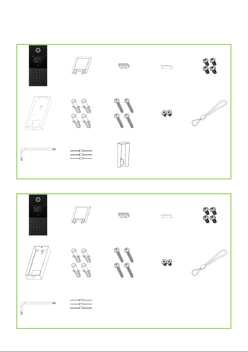
PACKAGE CONTENT
MODEL: VEX-B24A (Surface Mounting)
VEX-B24A Wiring Cover
Sealing Plug of
Wiring Port
Junction Pressing PWM3×8×7 (4 pcs)
Rear Cover
Screw Fixing Seat (4
pcs)
PA4×25 (4 pcs)
FM3×4.5 (2 pcs)
Hang rope
Wrench Screw Diode (3 pcs) Rain Hood (Optional)
MODEL: VEX-B24A (Flush Mounting)
VEX-B24A Wiring Cover
Sealing Plug of
Wiring Port
Junction Pressing PWM3×8×7 (4 pcs)
Flush Mounting Box
Screw Fixing Seat (4
pcs)
PA4×25 (4 pcs) FM3×4.5 (2 pcs) Hang rope
Wrench Screw Diode (3 pcs)
- 3 -
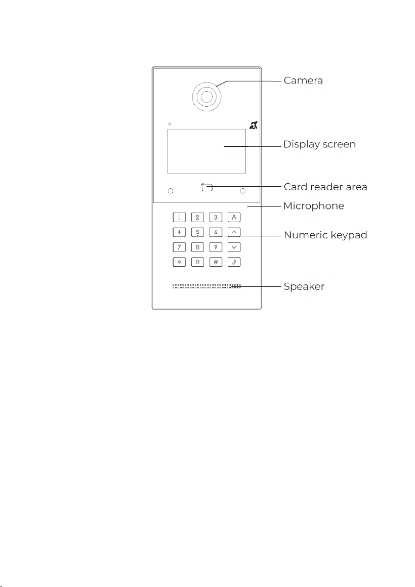
OVERVIEW

- 4 -
BASIC OPERATION
1. Call and Monitor
1.1 Call Indoor Monitor
In standby mode, press room numbers + #/dial on Door Station to call Indoor Monitor.
During the call, press * on Door Station again to end the call. If the call fails or Indoor
Monitor is busy, Door Station will make a beep sound.
1.2 Monitor Door Station
Click Monitor icon on Indoor Monitor’s homepage to monitor Door Station.
2. Phonebook
Click up or down button to enter phonebook page. You can dial any residents in this
phonebook.
3. Unlock
Press #+PIN Code+# to unlock.
4. Concierge
Press concierge button to call Master Station.
5. Facial Recognition
Press * twice to wake up face scan. Facial recognition should be enabled beforehand.
- 5 -
DEVICE SETTING
Connect Door Station and PC to a network switch in the same LAN. You can enter the
admin settings of Door Station by pressing # twice and entering default password
(123456). This is where you can configure the device.
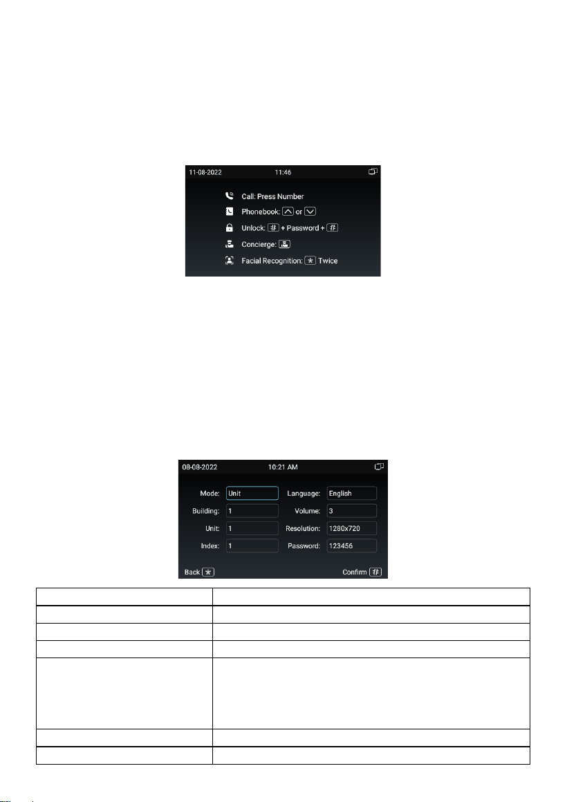
1. Device Settings
Numbers here are basic settings for making a call to Indoor Monitor. For Door Station,
the building and unit number should be the same as those in Indoor Monitor. For Villa
Station with one button, the building, unit, and room number should be the same as
those in Indoor Monitor.
The Index number here is to distinguish different Door Stations when more than one
Door Station in one building.
Mode:
Mode for apt., wall or villa (Unit and wall)
Building:
Number of the building (Building range: 1-999);
Unit:
Number of the unit (Unit range: 1-99);
Index:
Number of the Index (Unit range: 1-9);
Language:
16 languages supported (简体中文, English, 繁體中
文, תי ִרב ִﬠ, Deutsch, Español, Türk, Tiếng Việt,
Nederlands, Português, Polski, Русский, ﻲﺑرﻋ
,
Français, Italiano, slovenský);
Volume:
Volume of System can be set from 1 to 6;
Resolution:
3 resolutions supported (320 × 240, 640 × 480, 1280
- 6 -
× 720);
Password:
Administrator password of the Device (Default
123456);
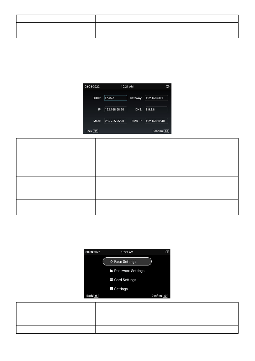
2. Network Settings
The device network can be set to either DHCP or a static IP address. CMS parameters
should be configured here when you try to register this device to CMS.
DHCP:
Enable DHCP (Dynamic Host Configuration
Protocol) to dynamically distributing network
configuration parameters;
IP:
Configure Static IP address to manually distributing
network configuration parameters;
Mask:
Subnet mask;
Gateway:
A component that is part of two networks, which
use different protocols;
DNS:
Domain Name Server of the device;
CMS IP:
Server address of CMS;
3. Access Settings
You can configure face, PIN code, card, and other settings.
Face Settings:
Manage face recognition;
Password Settings:
Manage PIN codes;
Card Settings:
Manage cards;
Settings:
Manage all other access related settings;
- 7 -
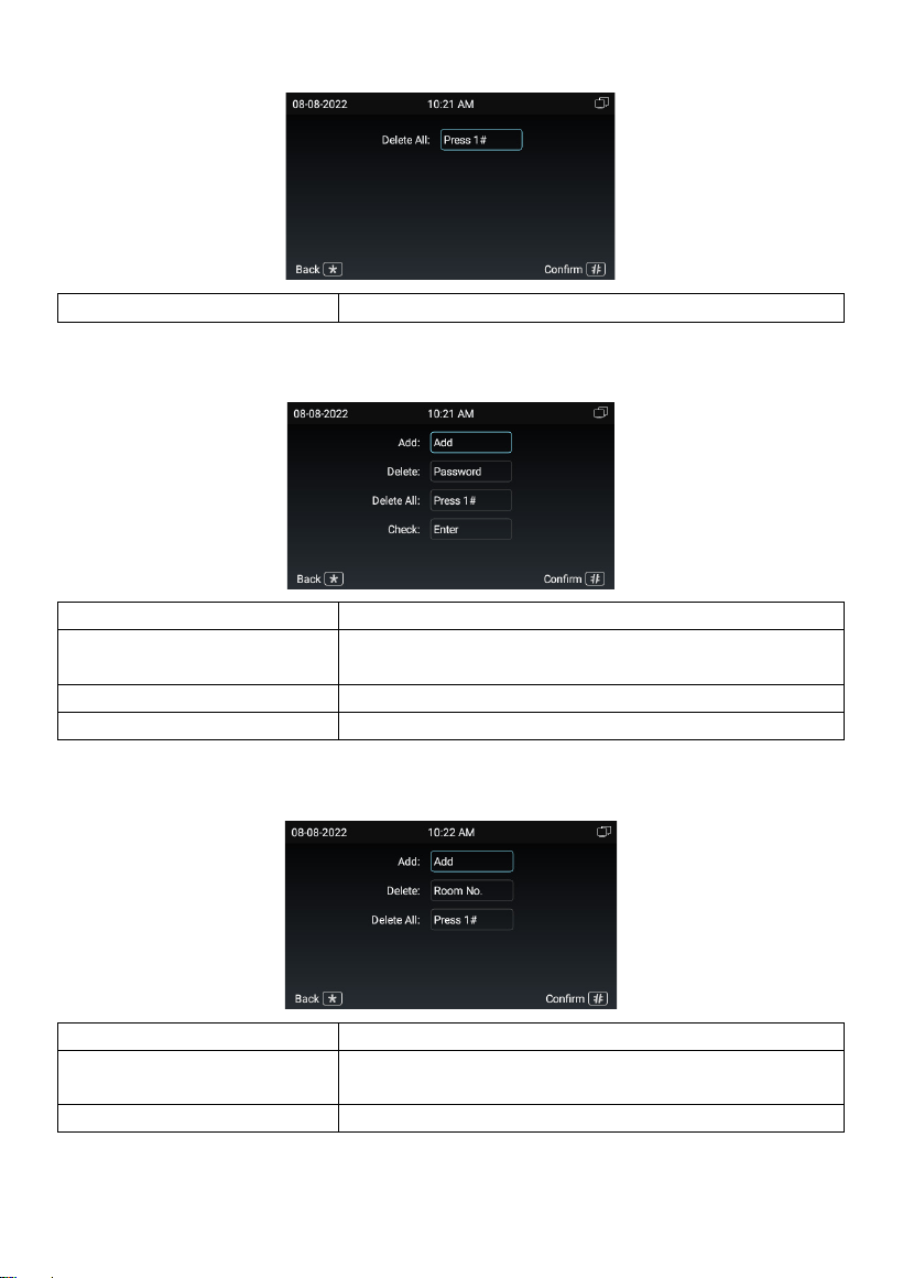
3.1 Face Settings
Delete All:
Press 1 + # to delete all face info;
3.2 Password Settings
Add:
Press # to add PIN code for different relays;
Delete:
Press PIN code to delete PIN code under this room
number;
Delete All:
Press 1 + # to delete all PIN codes;
Check:
Press # to check all PIN codes and related relays;
3.3 Card Settings
Add:
Press # to add cards;
Delete:
Press room number to delete cards under this room
number;
Delete All:
Press 1 + # to delete all cards;
- 8 -
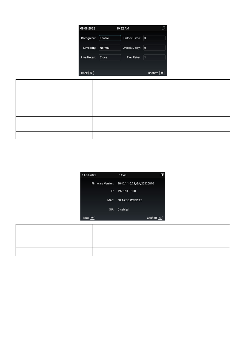
3.4 Settings
Recognizer:
Enable to use face recognition;
Similarity:
Sensitivity of facial similarity analyzer (Low, normal,
high);
Live Detect:
Sensitivity of live detect to prevent picture fraud or
video fraud (Close, normal, high);
Unlock Time:
The length of unlock time (1-9s);
Unlock Delay:
The length of unlock delay time (1-9s);
Elev Refer:
The floor Door Station is installed at (Range: -9-99);
4. About System
You can find basic information displayed in About System.
Firmware Version:
Firmware version of the device;
IP:
Current IP address of the device;
MAC:
MAC address of the device;
SIP:
Status of SIP registration of the device;
- 9 -
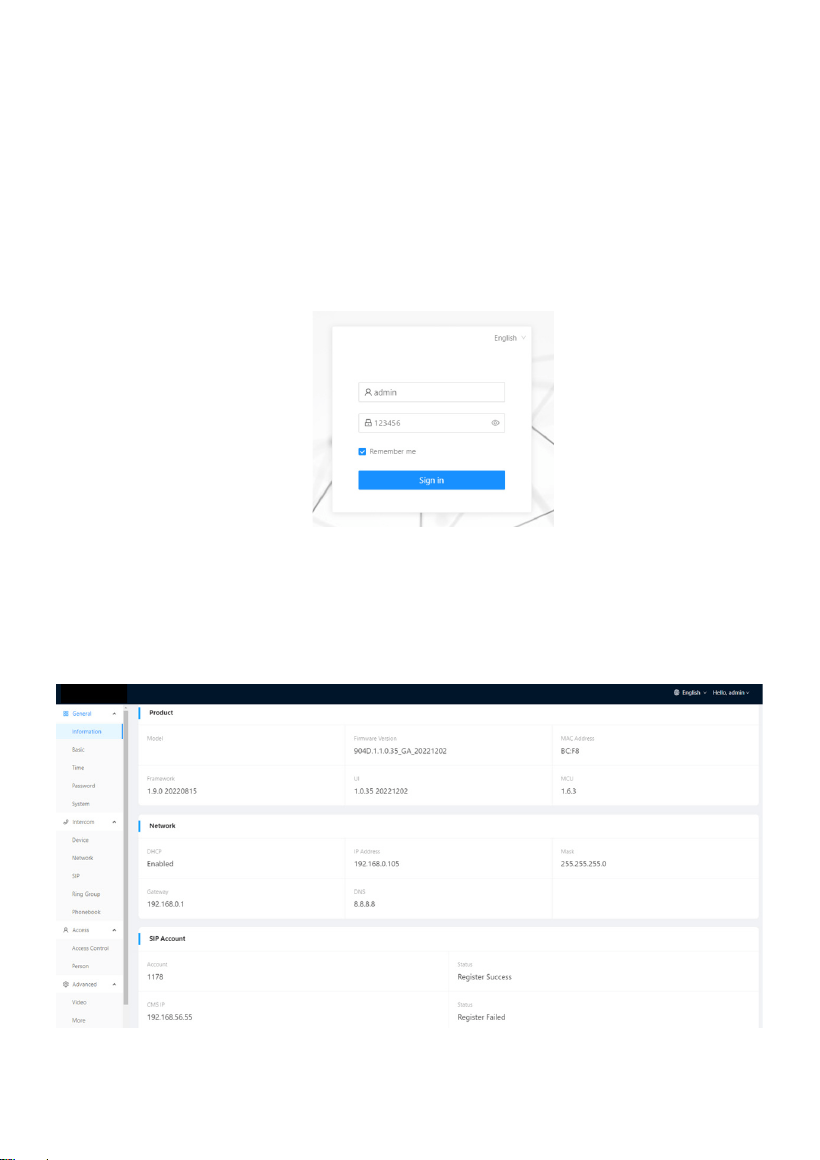
WEB SETTING
Connect Door Station and PC to a network switch in the same LAN. You can enter the
IP address of Door Station in the web browser search bar and log in with the default
account (admin) and password (123456). This is where you can configure the device.
For getting the IP address, you can search by Remote Upgrade Tool which is installed
in the same LAN with the devices.
1. General
1.1 General > Information
When you first log in to the web interface, you can find basic information displayed in
this dashboard.
- 10 -
Model:
Model of the device;
Firmware Version:
Firmware version of the device;
MAC Address:
MAC address of the device;
Framework:
Framework of the device;
UI:
UI of the device;
MCU:
MCU of the device;
DHCP:
Status of DHCP;
IP Address:
Current IP address of the device;
Mask:
Subnet mask of the device;
Gateway:
Gateway of the device;
DNS:
Domain Name Server of the device;
Account:
SIP account of the device;
Status:
Status of SIP registration of the device;
CMS IP:
IP address of CMS;
Status:
Status of CMS registration;
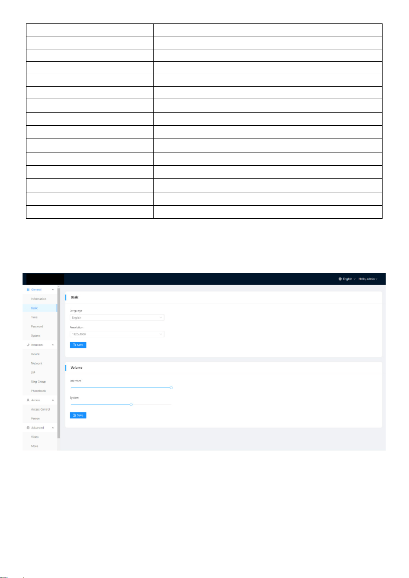
1.2 General > Basic
Language, resolution and volume of the device can be configured in this column.
- 11 -
Language:
16 languages supported (简体中文, English, 繁體中
文, תי ִרב ִﬠ, Deutsch, Español, Türk, Tiếng Việt,
Nederlands, Português, Polski, Русский, ﻲﺑرﻋ
,
Français, Italiano, slovenský);
Resolution:
3 resolutions supported (320 × 240, 640 × 480, 1280
× 720);
Intercom:
Volume of Intercom can be set from 1 to 6;
System:
Volume of System can be set from 1 to 6;
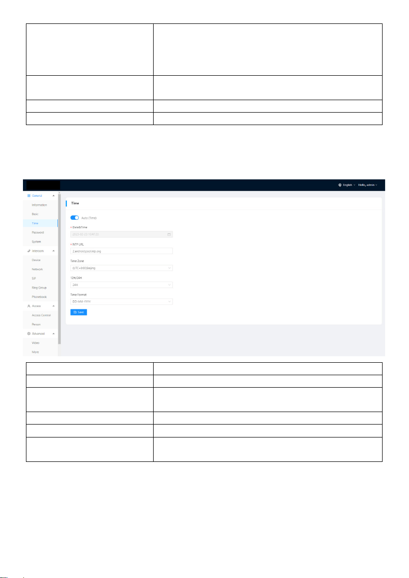
1.3 General > Time
Time of the device can be configured.
Daylight Saving Time is also supported.
Auto (Time):
Enable to synchronize computer time;
Date&Time:
Date and time can be set manually;
NTP URL:
Network Time Protocol (NTP) is a protocol used to
synchronize computer time;
Time Zone:
A region that observes a uniform standard time;
12H/24H:
Select 12H or 24H format to display on the device;
Date Format:
3 time formats supported (YYYY-MM-DD, DD-MM-
YYYY, MM-DD-YYYY);
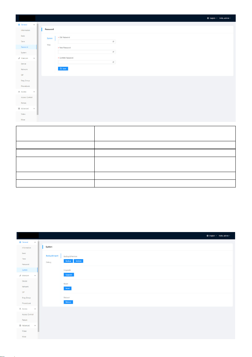
1.4 General > Password
The System password is for the administrator to log in settings on the device while the
Web password is for the administrator to log in settings on the web. The default
password for both of them is 123456.
- 12 -
System Old Password:
Current administrator password of the Device
(Default 123456);
System New Password:
New administrator password of the Device;
System Confirm Password:
Confirm administrator password of the Device;
Web Old Password:
Current administrator password of the web (Default
123456);
Web New Password:
New administrator password of the web;
Web Confirm Password:
Confirm administrator password of the web;
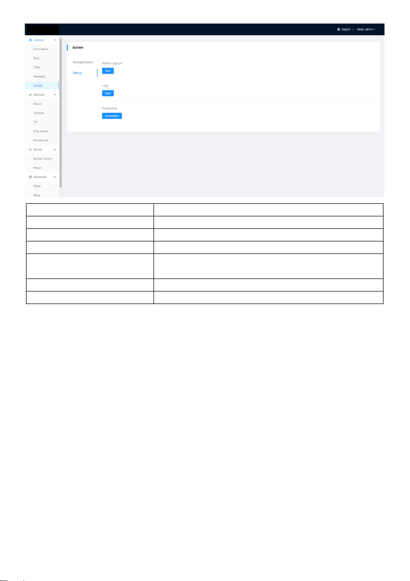
1.5 General > System
The system column is designed for data backup and restore, firmware upgrade, factory
default, device reboot, packet capture, logs capture, and obtaining UI screenshots.
- 13 -
Backup&Restore:
Backup all setting and restore settings;
Upgrade:
Upgrade equipment;
Reset:
Reset to factory settings;
Reboot:
Reboot the device;
Packet Capture:
Capturing packets can help developers reproduce
positioning problems;
Logs:
Device logs;
Screenshot:
Screenshot device interface;
2. Intercom
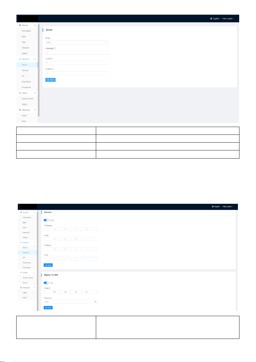
2.1 Intercom > Device
Numbers here are basic settings for making a call to Indoor Monitor. For Door Station,
the building and unit number should be the same as those in Indoor Monitor. For Villa
Station with one button, the building, unit, and room number should be the same as
those in Indoor Monitor.
The device number here is to distinguish different Door Stations when more than one
Door Station is in one building.
- 14 -
Mode:
Mode for apt. and wall (Unit and wall);
Building:
Number of the building (Range: 1-999);
Unit:
Number of the unit (Range: 1-99);
Index:
Number of the device (Range: 1-9);
2.2 Intercom > Network
The device network can be set to either DHCP or a static IP address. CMS parameters
should be configured here when you try to register this device to CMS.
DHCP:
Enable DHCP (Dynamic Host Configuration
Protocol) to dynamically distribute network
configuration parameters;
- 15 -
IP Address:
Configure Static IP address to manually distribute
network configuration parameters;
Mask:
Subnet mask;
Gateway:
A component that is part of two networks, which
use different protocols;
DNS:
Domain Name Server of the device;
CMS:
Enable to use CMS software to manage devices;
CMS IP:
Server address of CMS;
Password:
Password you set for this device’s CMS registration;
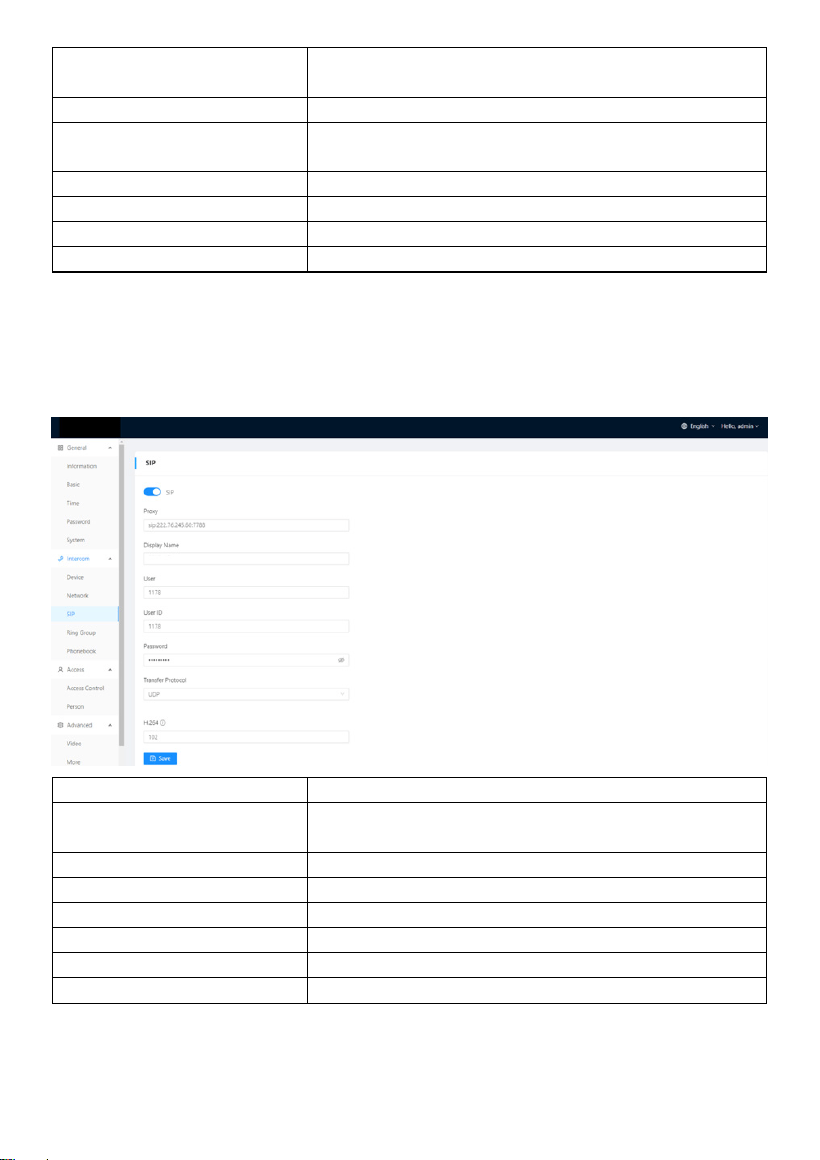
2.3 Intercom > SIP
The SIP column concerns SIP registration, Display Name, Register Name, Username,
Password, SIP Server Host, Outbound Proxy, Transfer Protocol, Video Payload, etc.
SIP:
Enable to use SIP;
Proxy:
Fill in sip:SIP server’s address:port e.g.,
sip:192.168.68.90:5060;
Display Name:
Display name of SIP;
User:
Register Name of SIP;
User ID:
Username of SIP;
Password:
Password of SIP;
Transfer Protocol:
Transfer Protocol (UDP, TCP, TLS);
H.264:
Video payload range is 96-127;
- 16 -
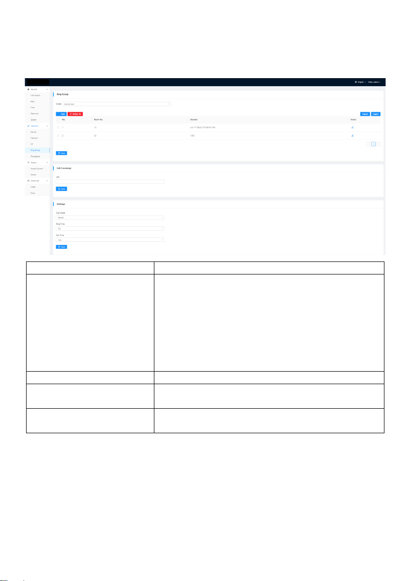
2.4 Intercom > Ring Group
Ring group is for setting up SIP calls or call mode. Concierge button, the length of the
call and ring time can also be configured here.
Mode:
2 modes supported (one by one, all at once);
Call Concierge URL:
Fill in the call destination for concierge button or
the single button on the device;
IP call:
Fill in sip:IP address,
e.g., sip:192.168.68.90;
SIP call:
Fill in sip:sip account@SIP server address:port, e.g.,
sip:101@192.168.68.90:5060;
Dial Mode:
2 dial modes supported (Normal, Repeat);
Ring Time:
The ring will be ended automatically after a period
of time (10s, 20s, 35s, 45s, 60s, 90s, 120s)
Call Time:
The call will be ended automatically after a period of
time (120s, 300s, 600s, 1200s, 1800s);
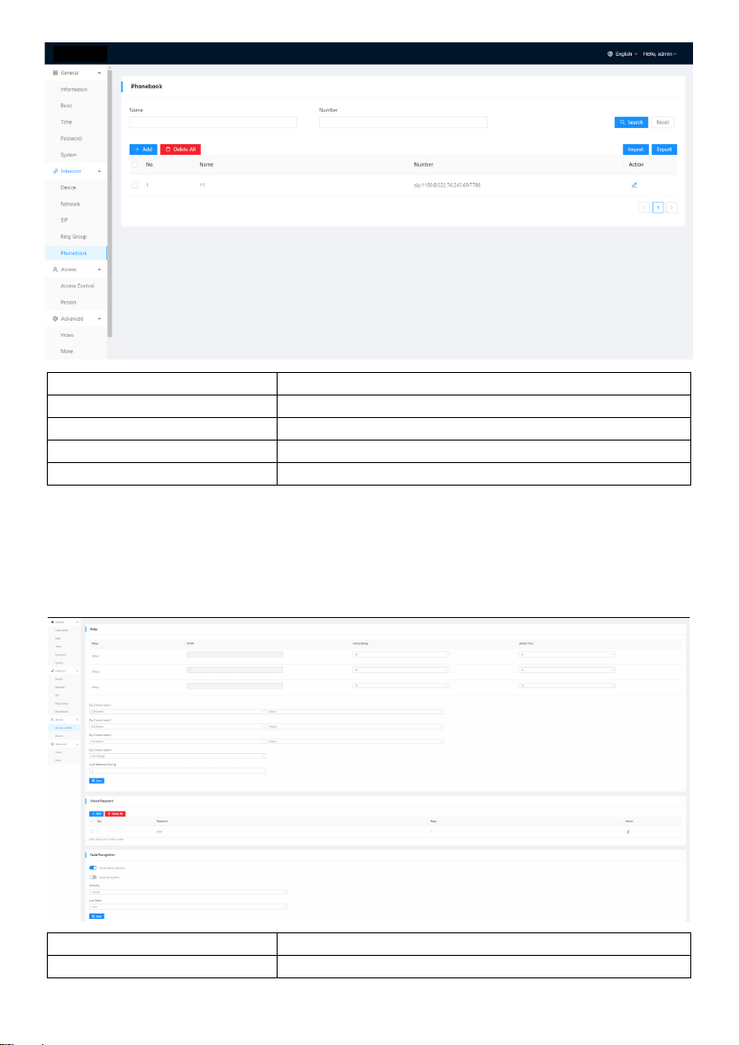
2.5 Intercom > Phonebook
All contacts on Door Station can be edited here.
- 17 -
Search:
Fill in text inputs to search;
Reset:
Click reset to clear words in text inputs;
Delete All:
Delete all data on the chart;
Import:
Import all data to the chart;
Export:
Export all data on the chart;
3. Access
3.1 Access > Access Control
Relays, access cards, PIN code can be configured here.
Relay 1-3:
3 relays supported;
DTMF:
Dual-tone multi-frequency signaling (Relay1: #,
- 18 -
Relay2:0, relay3: *);
Unlock Delay:
The length of unlock delay time (1-9s);
Unlock Time:
The length of unlock time (1-9s);
Dry Contact Input 1-3:
3 modes of dry contact inputs are supported (Exit
Button, Door Sensor, Fire Linkage);
Lift Reference Floor:
The floor Door Station is installed at (Range: -9-99);
Master Card:
Click read to add Master card to manage cards;
Unlock Password:
Click to add PIN code or delete all;
Human Body Induction:
Once you approach to Door Station, face scan will
be enabled automatically;
Facial recognition:
Enable to use face recognition;
Similarity:
Sensitivity of facial similarity analyzer (Low, normal,
high);
Live Detect:
Sensitivity of live detect to prevent picture fraud or
video fraud (Close, normal, high);
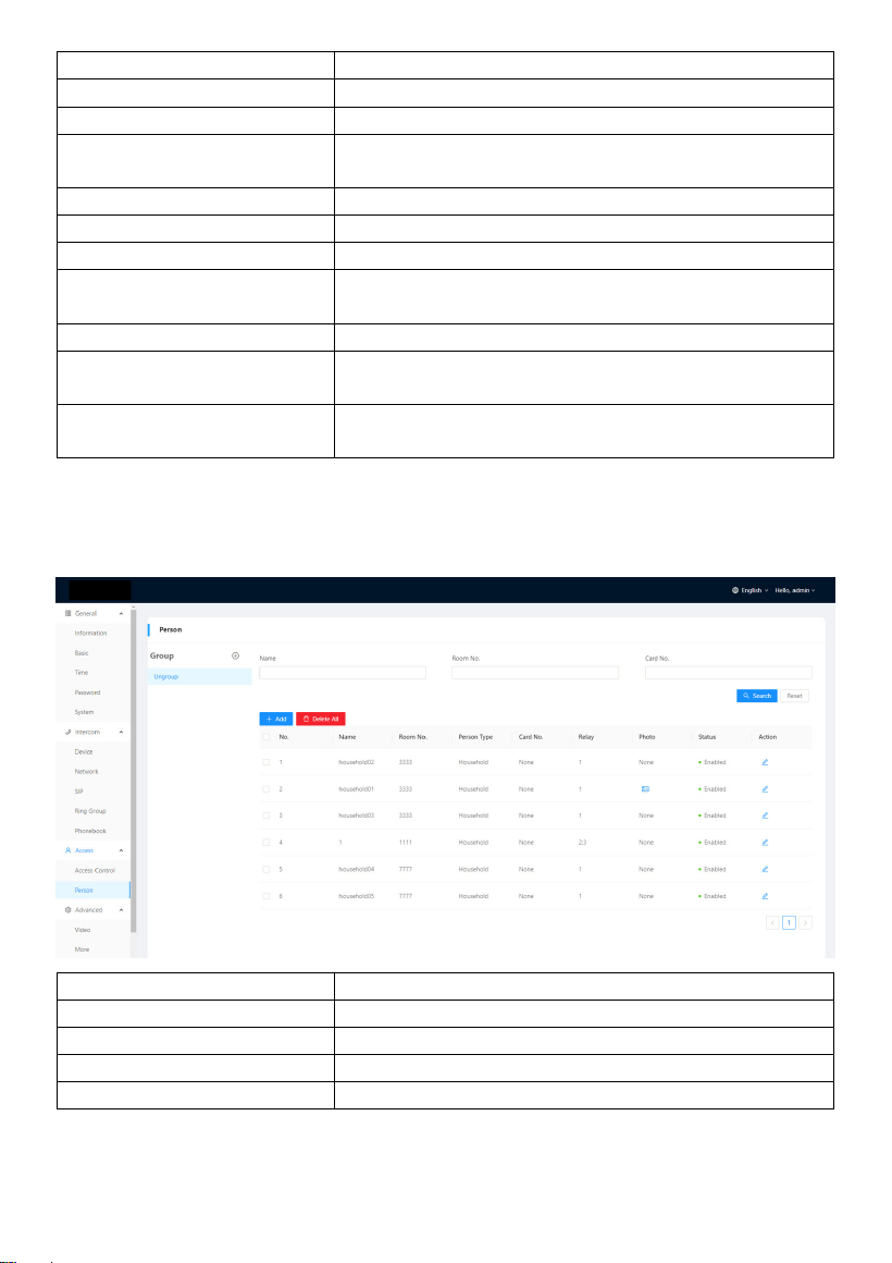
3.2 Access > Person
Person column is for access authorization.
Search:
Fill in text inputs to search;
Reset:
Click reset to clear words in text inputs;
Add:
Add users to Door Station;
Delete All:
Delete all data on the chart;
Export:
Export all data on the chart;
- 19 -
4. Advanced
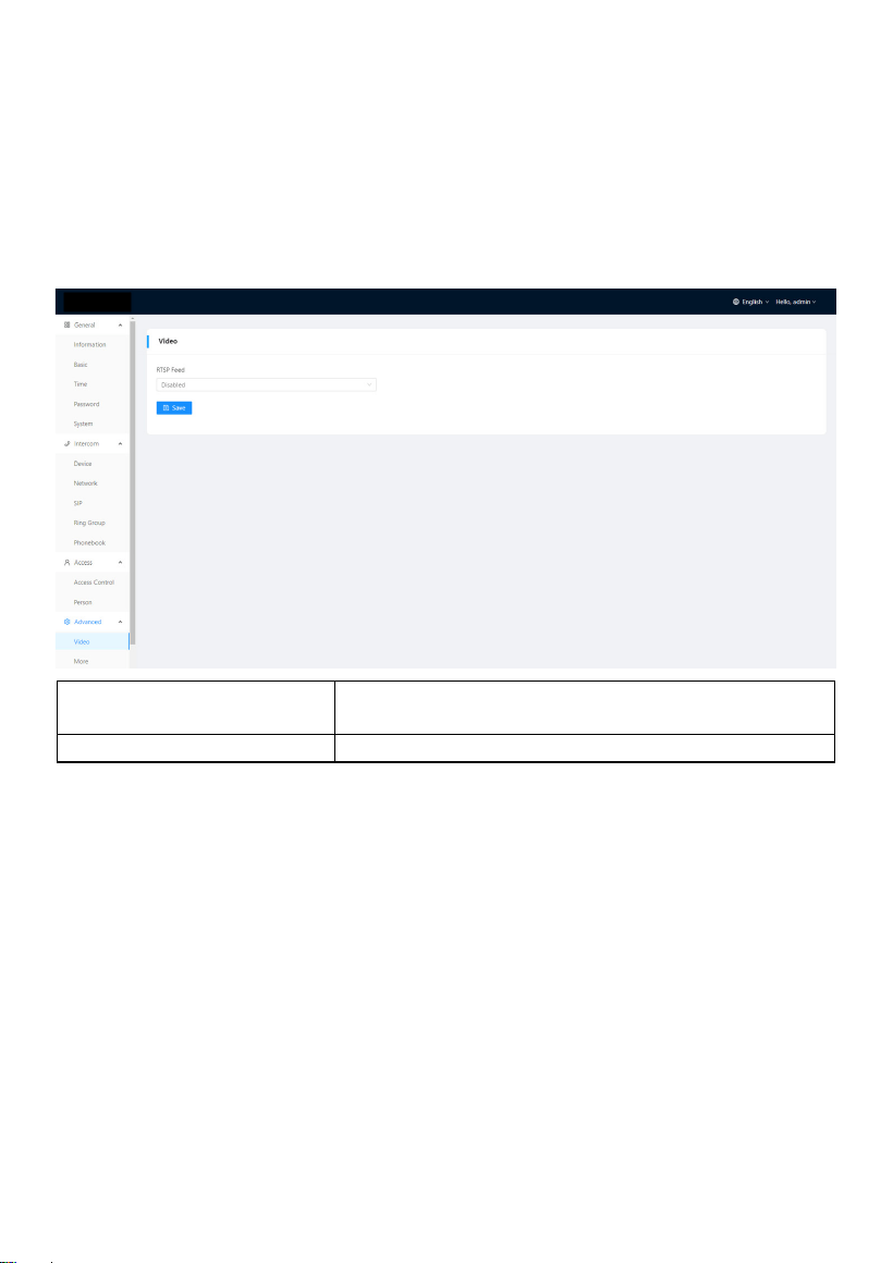
4.1 Advanced > Video
Real-time video from IP cameras can be obtained by filling in its URL (RTSP). On the
talking interface of Indoor Monitor, you can click the little keyboard icon to switch to IP
cameras’ video. (No.1 on the keyboard stands for Door Station while No.2 to No.5
stands for IP camera)
RTSP Feed:
4 IP cameras supported to switch while talking on
Indoor Monitor;
URL:
IP camera’s URL;
- 20 -
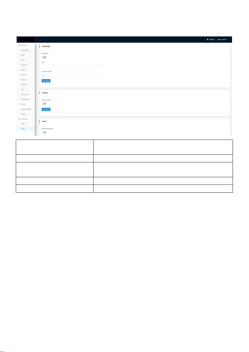
4.2 Advanced > More
More column is for Tamper Alarm and ONU Penetration.
Advertise:
Enable to advertise on the screen saver of the
device;
URL:
Advertise URL;
Time (minutes):
The time length of advertise display (10mins,
20mins, 30mins);
Tamper Alarm:
Enable to use Tamper alarm;
ONU Penetration:
Enable to prevent ONU from banning multicast;
- 21 -
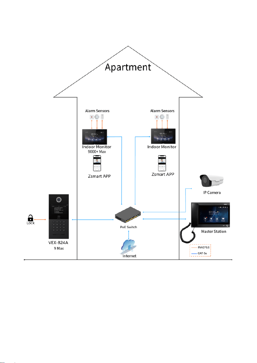
SYSTEM DIAGRAM
- 22 -
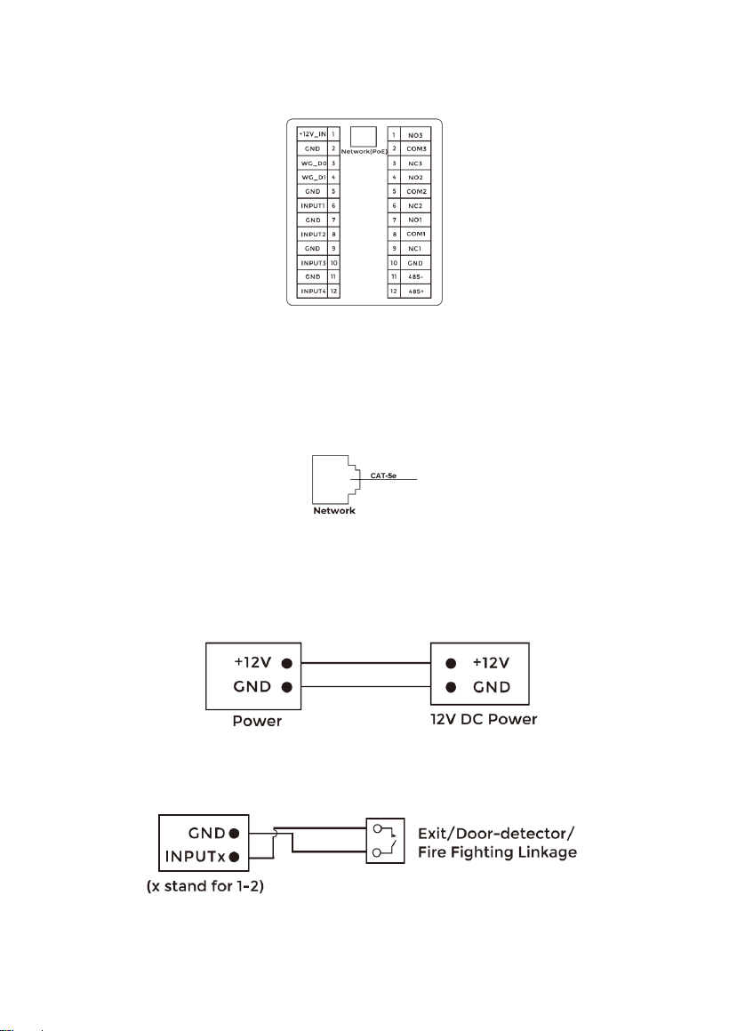
DEVICE WIRING
1. Network (PoE)
Standard RJ45 interface is for the connection with PoE+ switch or other network switch.
PSE shall comply with IEEE 802.3at (PoE+) and its output power not less than 30W and
its output voltage not be less than 50V.
2. Power
The power interface of Door Station connects to 12V DC power.
3. Exit/Door-detector/Fire Fighting Linkage
- 23 -
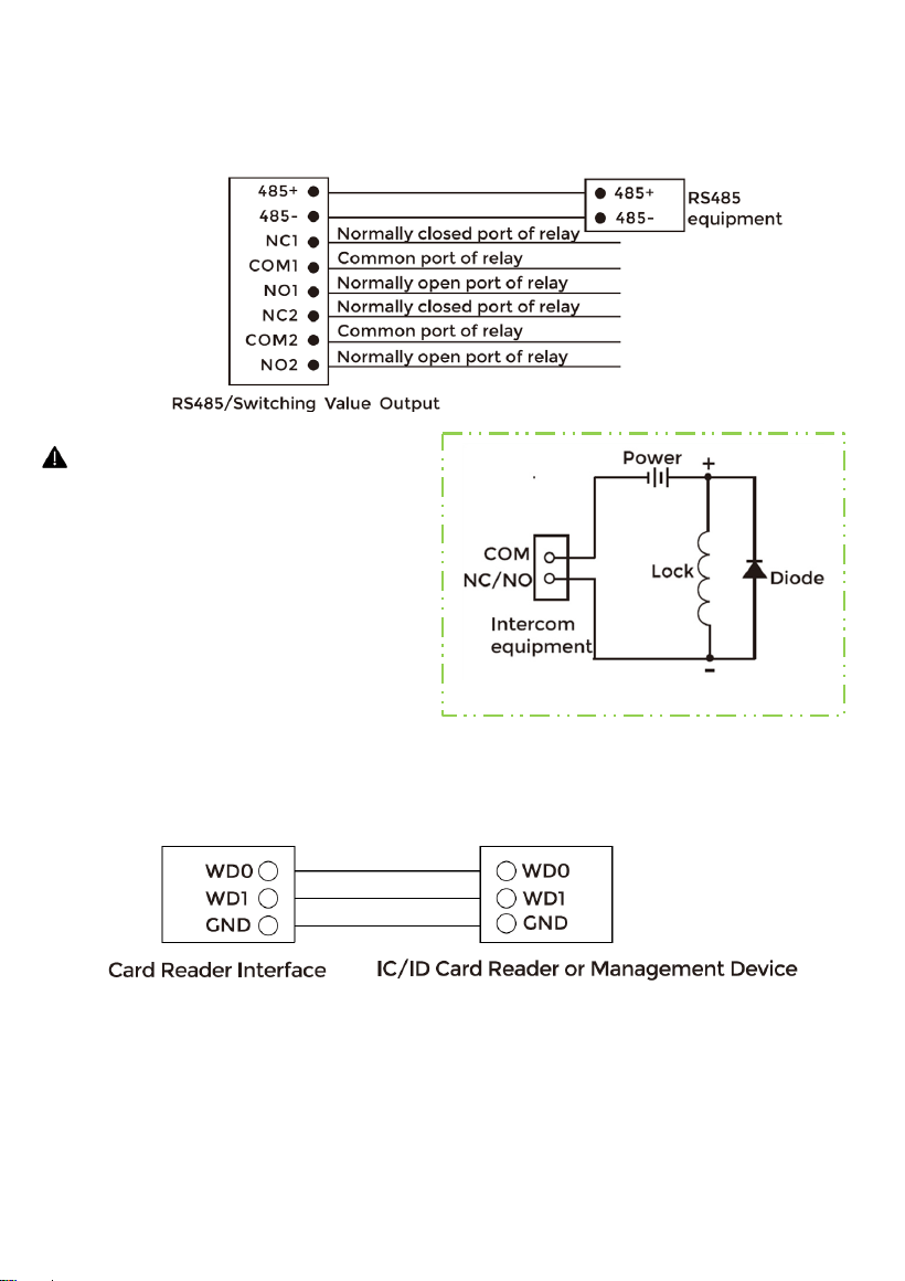
4. RS485/Switching Value Output
Enable to connect equipment with RS485 interface.
Connect to the lock module (an independent power supply is necessary for the lock).
5. Card Reader Interface
The interface can be connected to one IC/ID card reader or be used for reading the
information of built-in card reader.
Note: Door Station can only be connected to one card reader or management device
at a time.
Warning!
1. When connecting to an inductive load device such as a relay
or electromagnetic lock, you are recommended to use a diode
1A/400V (included in the accessories) in anti-parallel with the
load device to absorb inductive load voltage peaks. The
intercom will be better protected in this way.
2. The load current of the relay cannot be greater than 2A. See
attached picture for more details.
- 24 -
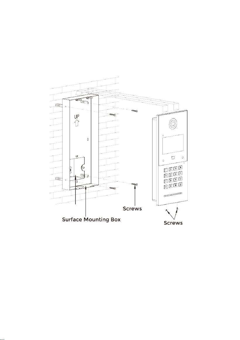
INSTALLATION
Surface Mounting-Asian Gang Box
Product size:
133 × 295 × 41 mm
Surface Mounting size:
133 × 295 × 43 mm
Asian Gang Box
- 25 -
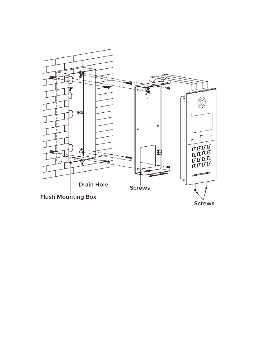
Flush Mounting
Product size:
133 × 295 × 41 mm
Flush Mounting size:
133 × 295 × 63.5 mm
Mounting hole size:
124 × 289 × 56 mm
- 26 -
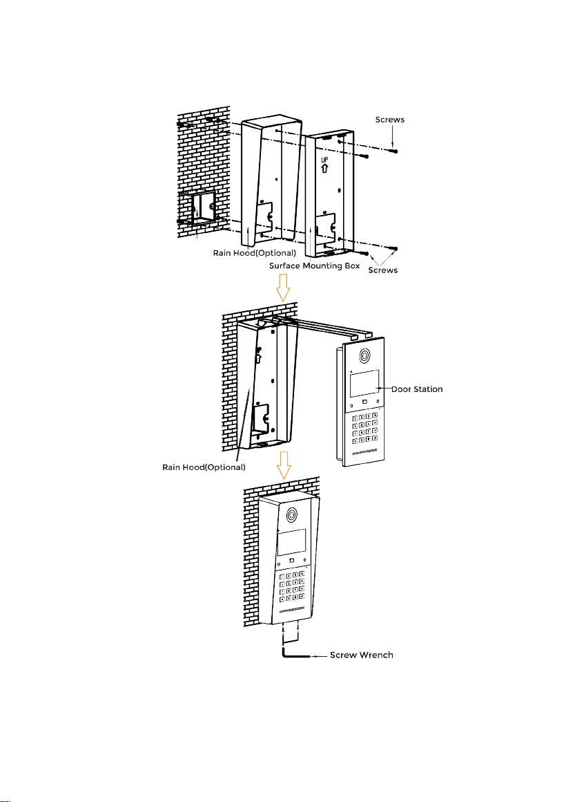
Surface Mounting & Rain Hood (Optional)
Product size:
133 × 295 × 41 mm
Surface Mounting size:
133 × 295 × 43 mm
Asian Gang Box
- 27 -
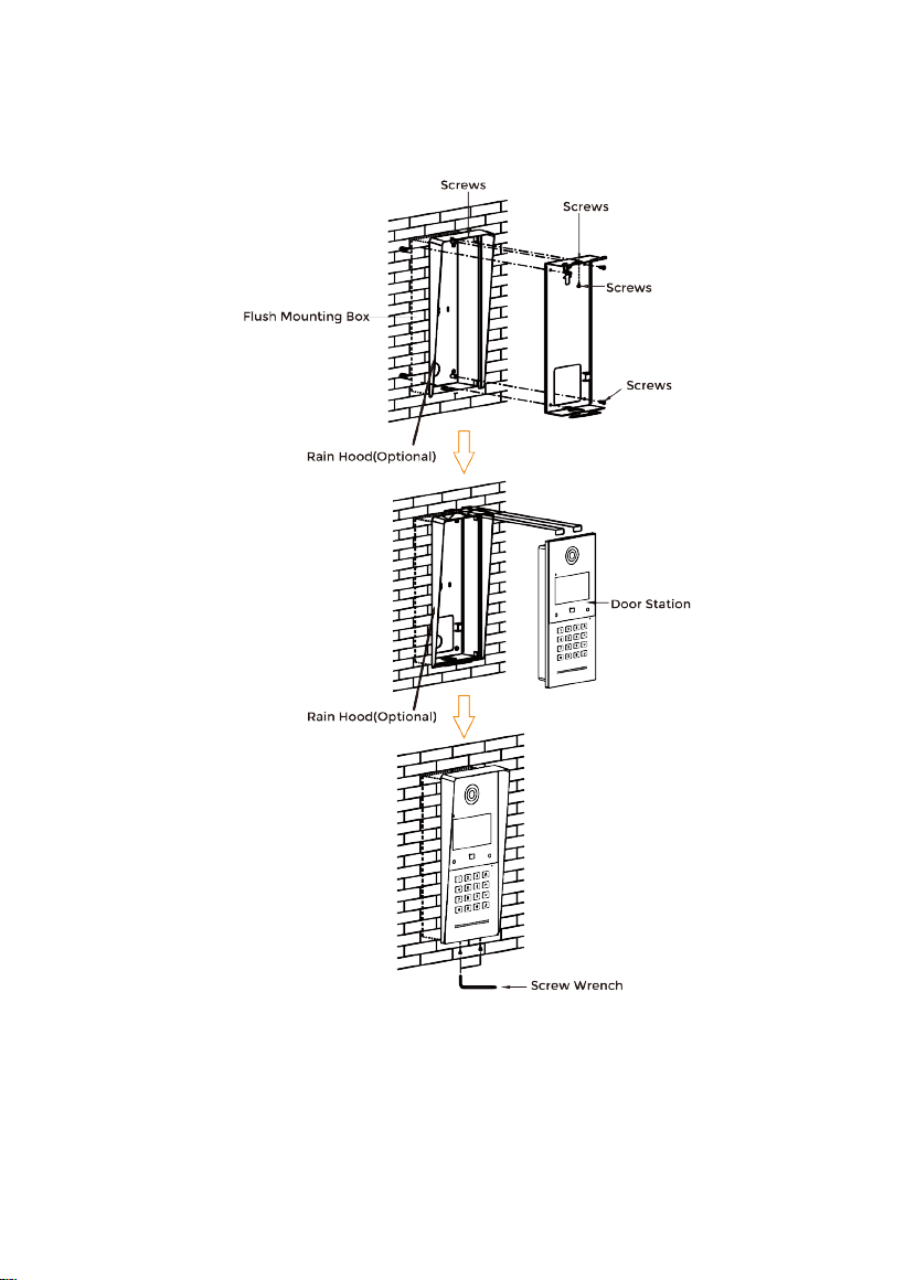
Flush Mounting & Rain Hood (Optional)
Product size:
133 × 295 × 41 mm
Flush Mounting size:
133 × 295 × 63.5 mm
Mounting hole size:
124 × 289 × 56 mm

- 28 -
Tips:
The camera should be 1450~1550mm above the ground. The
camera at this height can capture human face perfectly.

- 29 -
TROUBLESHOOTING
The Indoor Monitor cannot start up or power off automatically.
Check whether it has power-failure, and power it on again
The Indoor Monitor display screen is too dim.
Check whether the brightness and contrast settings of screen are correct.
No sound during the communication.
Check whether the Indoor Monitor is set as mute mode, or the volume is set to the
lowest.
The Indoor Monitor cannot monitor the Door Station.
Other user is using the system, so you can use it once he/she finished the operation.
Multimedia files cannot be played normally.
Check whether the system supports the file format. Please refer to the multimedia
setting for details.
No response when clicking Indoor Monitor display screen.
Press "Unlock" button for 5s, or slowly slide horizontally or vertically on the LCD to
make touchscreen calibration. It needs to be calibrated.
Touchscreen responses slowly or cannot make calibration.
Take down any protective paster, since it may affect identification
and input for device;
Ensure the finger is dry and clean when clicking touchscreen;
Restart the device to clear any temporary software error.
The temperature of device is too high.
Long-term use leads to high temperature. It’s normal and will not affect the
device’s use life and performance.

- 30 -
SAFETY INSTRUCTION
In order to protect you and others from harm or your device from damage, please read the
following information before using the device.
Do not install the device in the following places:
Do not install the device in high-temperature and moist environment or the area close to
magnetic field, such as the electric generator, transformer or magnet.
Do not place the device near the heating products such as electric heater or the fluid
container.
Do not place the device in the sun or near the heat source, which might cause discoloration
or deformation of the device.
Do not install the device in an unstable position to avoid the property losses or personal
injury caused by the falling of device.
Guard against electric shock, fire and explosion:
Do not use damaged power cord, plug or loose outlet.
Do not touch the power cord with wet hand or unplug the power cord by pulling.
Do not bend or damage the power cord.
Do not touch the device with wet hand.
Do not make the power supply slip or cause the impact.
Do not use the power supply without the manufacturer's approval.
Do not have the liquids such as water go into the device.
Clean Device Surface
Clean the device surfaces with soft cloth dipped in some water, and then rub the surface with
dry cloth.
Other Tips
In order to prevent damage to the paint layer or the case, please do not expose the device to
chemical products, such as the diluent, gasoline, alcohol, insect-resist agents, opacifying
agent and insecticide.
Do not knock on the device with hard objects.
Do not press the screen surface. Overexertion might cause flopover or damage to the device.
Please be careful when standing up from the area under the device.
Do not disassemble, repair or modify the device at your own discretion.
The arbitrary modification is not covered under warranty. When any repair required, please
contact the customer service center.
If there is abnormal sound, smell or fume in the device, please unplug the power cord
immediately and contact the customer service center.
When the device isn’t used for a long time, the adaptor and memory card can be removed
and placed in dry environment.
When moving, please hand over the manual to new tenant for proper usage of the device.

- 31 -
FCC Warning
This device complies with Part 15 of the FCC Rules. Operation is subject to the
following two conditions:
(1) This device may not cause harmful interference, and (2) this device must accept any
interference received, including interference that may cause undesired operation.
NOTE 1: This equipment has been tested and found to comply with the limits for a
Class B digital device, pursuant to part 15 of the FCC Rules. These limits are designed to
provide reasonable protection against harmful interference in a residential installation.
This equipment generates uses and can radiate radio frequency energy and, if not
installed and used in accordance with the instructions, may cause harmful interference
to radio communications. However, there is no guarantee that interference will not
occur in a particular installation. If this equipment does cause harmful interference to
radio or television reception, which can be determined by turning the equipment off
and on, the user is encouraged to try to correct the interference by one or more of the
following measures:
- Reorient or relocate the receiving antenna.
- Increase the separation between the equipment and receiver.
-Connect the equipment into an outlet on a circuit different from that to which the
receiver is connected.
-Consult the dealer or an experienced radio/TV technician for help.
NOTE 2: Any changes or modifications to this unit not expressly approved by the party
responsible for compliance could void the user's authority to operate the equipment.
RF exposure statement
This equipment complies with the FCC radiation exposure limits set forth for an
uncontrolled environment. This transmitter must not be co-located or operating in
conjunction with any other antenna or transmitter.

ZKTeco Industrial Park, No. 32, Industrial Road,
Tangxia Town, Dongguan, China.
Phone : +86 769 - 82109991
Fax : +86 755 - 89602394
www.zkteco.com
Copyright © 2024 ZKTECO CO., LTD. All Rights Reserved.


