Read Carefully Before Use
Keep for Future Reference
UM-LHJ-0001-V1
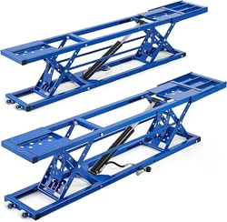
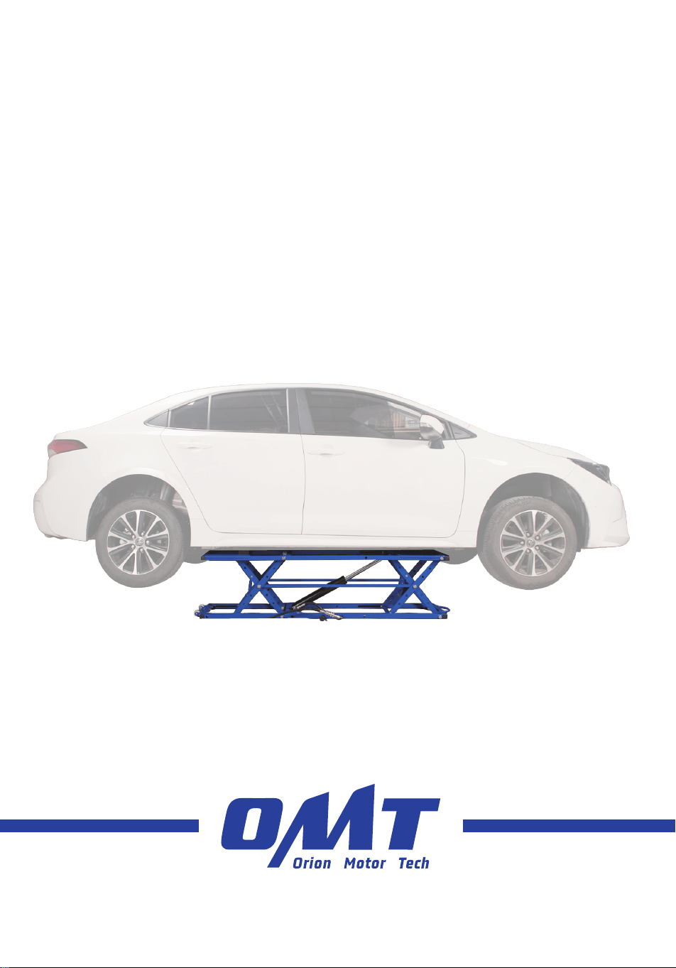
Portable Car Lift
User Manual

How did we get our start?
Orion Motor Tech began with a passion for cars. We started out by maintaining family cars in
our home garage but quickly found that affordable quality tools are hard to come by. That’s why
we made it our mission to put durable tools in the hands of do-it-yourself repairmen—so you
can get the job done right.
What makes our products unique?
We have a wide inventory of quality automotive tools and parts, covering almost all makes and
models. As a professional manufacturer, we are driven to make top-quality products affordable
for both professional and amateur mechanics.
Why do we love what we do?
We’re still in love with cars—just like we were back in that old family garage. We hope to pass
that passion on to all our customers, and we still believe in our old motto: You don’t need more
cars in your life. You need more life in your car.
@OrionMotorTech
More Life in Every Mile

Content
Safety Information ................................................................................................................ 1
Specifications ........................................................................................................................ 2
Parts List ................................................................................................................................ 3
Assembly ................................................................................................................................ 4
Operation ...............................................................................................................................8
Adding the Hydraulic Oil ........................................................................................................................... 8
Lifting the Vehicle ...................................................................................................................................... 12
Maintenance ......................................................................................................................... 14
Troubleshooting ................................................................................................................... 15
Disposal ................................................................................................................................ 17

@OrionMotorTech
Read this disclaimer completely and carefully before
proceeding with the rest of the manual content.
1. Product Modifications
Any modifications or alterations to Orion Motor Tech (OMT)
products void any warranties and may result in damage or
injury. OMT shall not be liable for any damages resulting
from such modifications or alterations.
2. Compliance with Laws
Customers shall be liable for ensuring that the use of
OMT products complies with all applicable laws and
regulations in their respective jurisdictions. OMT shall not
be responsible for any violations of laws or regulations
resulting from the use of OMT products.
3. Correct Use
Always use OMT products only as directed in the
accompanying manuals. Failure to follow instructions may
result in injury or damage.
Always ensure the assembly, installation, operation,
maintenance, or repair of OMT products is carried out by
a competent person.
Regular maintenance should be performed throughout
the lifecycle of OMT products. You are responsible for
ensuring the products operate as intended.
Always wear appropriate protective gear.
4. Third–Party Products
OMT shall not be liable for any damages or losses
resulting from the use of third–party products in
conjunction with OMT products. Customers shall refer to
the third–party's guidelines and/or warranties (if any) for
any third–party products used.
5. Limitation of Liability
OMT shall not be liable for any direct, indirect, punitive,
incidental, special, or consequential damages to property
or life, whatsoever arising out of or connected with the
use or misuse of OMT products. In no event shall OMT’s
liability exceed the value of the products sold.
6. Warranty
Refer to the sales page for warranty information.
This disclaimer states the entire obligation of OMT with
respect to OMT products. If any part of this disclaimer is
determined to be void, invalid, unenforceable, or illegal,
including but not limited to the warranty disclaimers, liability
disclaimers, and liability limitations set forth above, the invalid
or unenforceable provision will be deemed superseded by
a valid and enforceable provision that most closely matches
the intent of the original provision and the remainder of the
agreement shall remain in full force and effect.
Disclaimer

1
Safety Information
• The instructions provided here are for general information only. ALWAYS perform all repairs in full compliance with your
vehicle’s service manual. After completing any repair, test your vehicle in your workshop at a low speed before resuming
regular use. Failure to do so may result in serious property damage and severe personal injury.
• DO NOT allow use by children, individuals with mental or physical conditions that may impair safe operation, or persons
unfamiliar with this product and its compatible air conditioning, oil, and transmission systems.
• Children MUST NOT play with the lift.
• Keep the power unit and its cord out of the reach of children under 8 years old.
• NEVER leave the lift unattended when it is connected to a power supply.
• If the supply cord is damaged, the power unit should be scrapped or have the cord replaced by the manufacturer, its
service agent, or similarly qualified persons to avoid hazards.
• ALWAYS wear appropriate personal protective equipment (PPE) during use. Required PPE may include eye, respiratory, and
hand protection, depending on your application or work environment. Respiratory protection must be capable of filtering all
particles generated by your work, even when working outdoors. A dust mask or respirator is highly recommended. Anyone
allowed nearby during use should wear equivalent PPE.
• ALWAYS read and understand your vehicle's specific safety warnings and instructions before using this kit. Use the
correct fluids, pressures, adapters, and other necessary components for your vehicle. Ensure the parking brake is engaged
before beginning any work. Use a jack and jack stands that can fully support the necessary weight. Never touch any heated
surface with exposed skin.
• DO NOT overreach. Keep proper footing and balance at all times.
• DO NOT use damaged or crushed hoses. High-pressure leaks can penetrate the skin and cause severe injury. If injured,
seek medical attention immediately.
• DO NOT pull the pendant control or power unit cable when moving the AC power unit.
• Maintain this product. Check for misalignment, binding, wear, or other damage before use. If any damage is detected,
repair or replace the faulty components before further use. In a large shop, mark such a tool “DO NOT USE” until it has
been repaired. ON LY replace components with identical parts.
• NEVER use the lift to raise vehicles exceeding the specified weight capacity.
• Avoid using extension cords, as they may overheat.
• NEVER remain in the vehicle during the lifting process.
• NEVER work under a lifted vehicle unless it is properly supported. ALWAYS use additional support.
• Before approaching a raised vehicle, ensure that all four locking teeth are securely engaged.
• DO NOT use this product if you are tired or under the influence of drugs, alcohol, or strong medication.
• For best results, keep the kit clean and dry. Remove any fluid, oil, or grease before and after work, particularly from the
handle and fittings.
• DO NOT use excessive pressure on this product and do not force it or its attachments.
• ENSURE the vehicle is secure when supported by a jack or lift.
• Dress appropriately for automotive servicing. Do not wear loose clothing or jewelry. Keep hair, clothing, gloves, hoses, and
tools away from moving parts during use.
• In case of an accident or injury, keep a first aid kit and a communication device (e.g., a phone) readily available. Be familiar
with the location of nearby emergency medical facilities.
• Automotive repair is an inherently dangerous activity. This manual and the separate vehicle service manual cannot cover all
possible situations that may arise. ALWAYS exercise discretion and good judgement. Seek training if needed.
• DO NOT remove the cap of the power unit while the lift is operating.
• Use the hydraulic power unit at room temperature. DO NOT operate above 150 ℉ .
• Use this lift ONLY on solid, level ground capable of supporting the vehicle’s weight.

2
Specifications
Model 5000 lb Lift 7000 lb Lift
Power Supply 110–120 V AC, 60 Hz
Power 0.75 kW
Tank 1.0 gal/3.8 L
Hydraulic Oil (Not Included) 46#
Load Capacity 5000 lb 7000 lb
Maximum Lifting Height* 1.97 ft 2.13 ft
Dimensions 80.7 × 22.4 × 15.4 in 80.7 × 22.4 × 16.9 in
Weight 482 lb 488 lb
*The specified lifting height includes the height of the blocks.
3
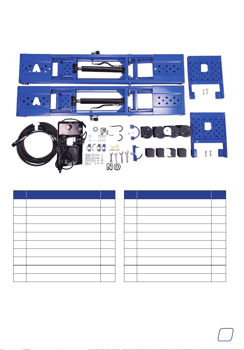
Parts List
No. Item Qty.
A Frame Assemblies 2
B Extension Plates 2
C Bolts, Washers, & Nuts M10 4
D Handles with Bolts, Washers, & Nuts M14 2
E Hooks 2
F Expansion Bolts M6 2
G Tape 1
H Bolts, Washers, & Nuts M8 8
I Rollers 4
J O-Rings 24
No. Item Qty.
K Replaceable Rollers 2
L Bolts and Nuts M5 2
M Filter Rings 2
N Double-End Wrench 1
O Wrench 14 mm 1
P Wrenches 22 mm 2
Q Round Rubber Blocks 4
R Square Rubber Blocks 4
S Hydraulic Power Unit with Pendant Control 1
T Oil Hoses 2
AA
AA
BB
BB
CC
CC
TT
SS
GG
FF
HH
II
JJ
NN OO PP
MM
EE
KK
LL
DD
DD
QQ
RR
4
Assembly
• ALWAYS wear appropriate personal protective equipment (PPE) during use. Required PPE
may include eye, respiratory, and hand protection, depending on your application or work
environment.
• For safety, at least two people are required for this assembly.
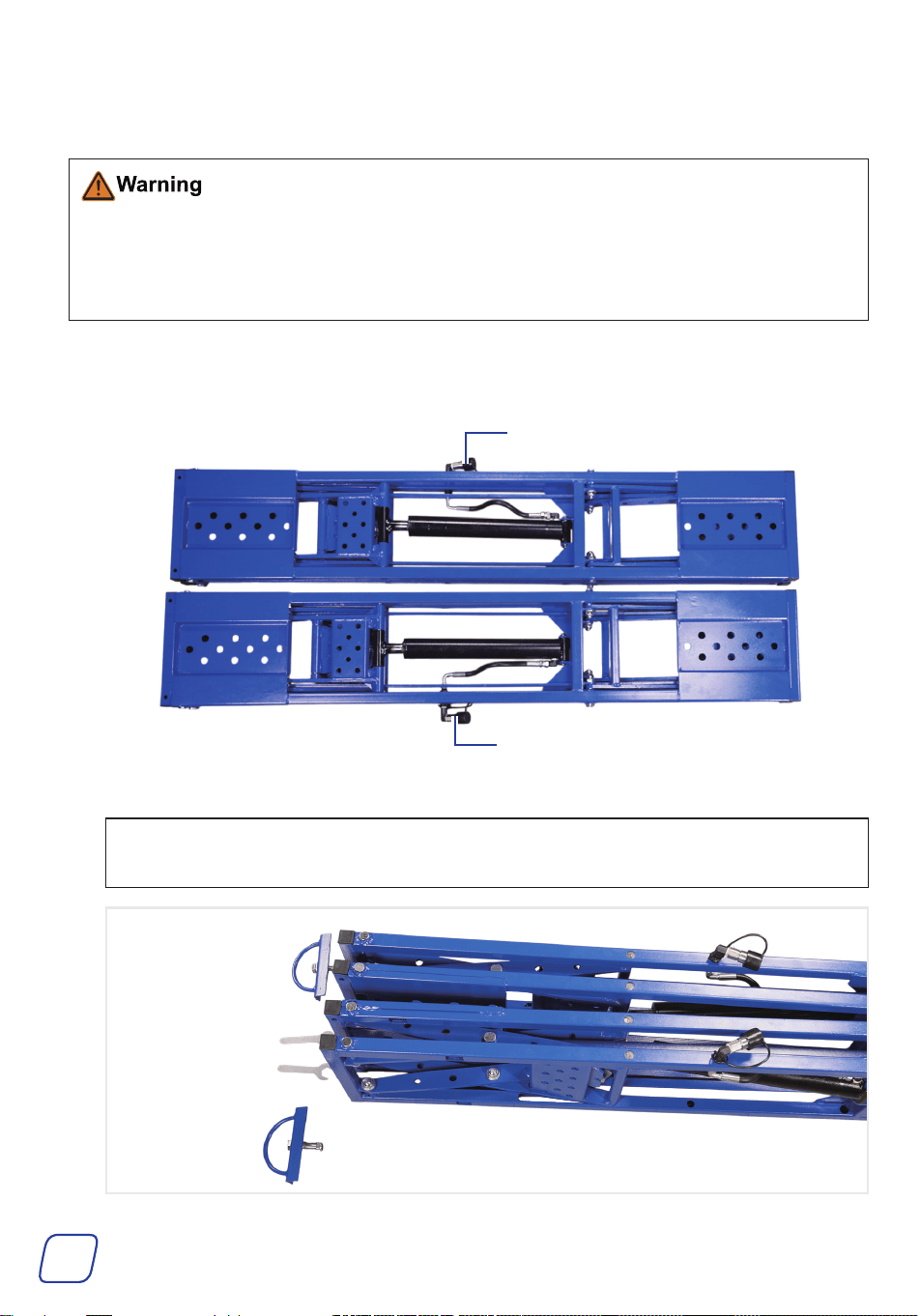
1. Unpack the frame assemblies (A) from the wooden crate.
Ensure that the hydraulic quick couplers are facing outward.
2. Turn the frame assemblies on their sides.
Note
Ensure that the side with the hydraulic quick couplers is positioned upward.
Hydraulic Quick Coupler
Hydraulic Quick Coupler
5
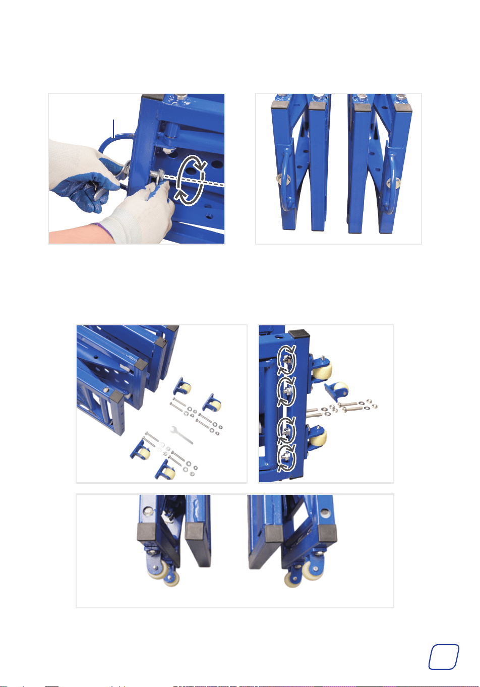
3. Remove the bolts from the handles (D). Attach the handles to the frame assemblies, and
tighten with two 22 mm wrenches (P).
4. Install the rollers (I) on the opposite side of the handles using M8 bolts, washers, and nuts (H),
then tighten with the 14 mm wrench (O).
Handle
6
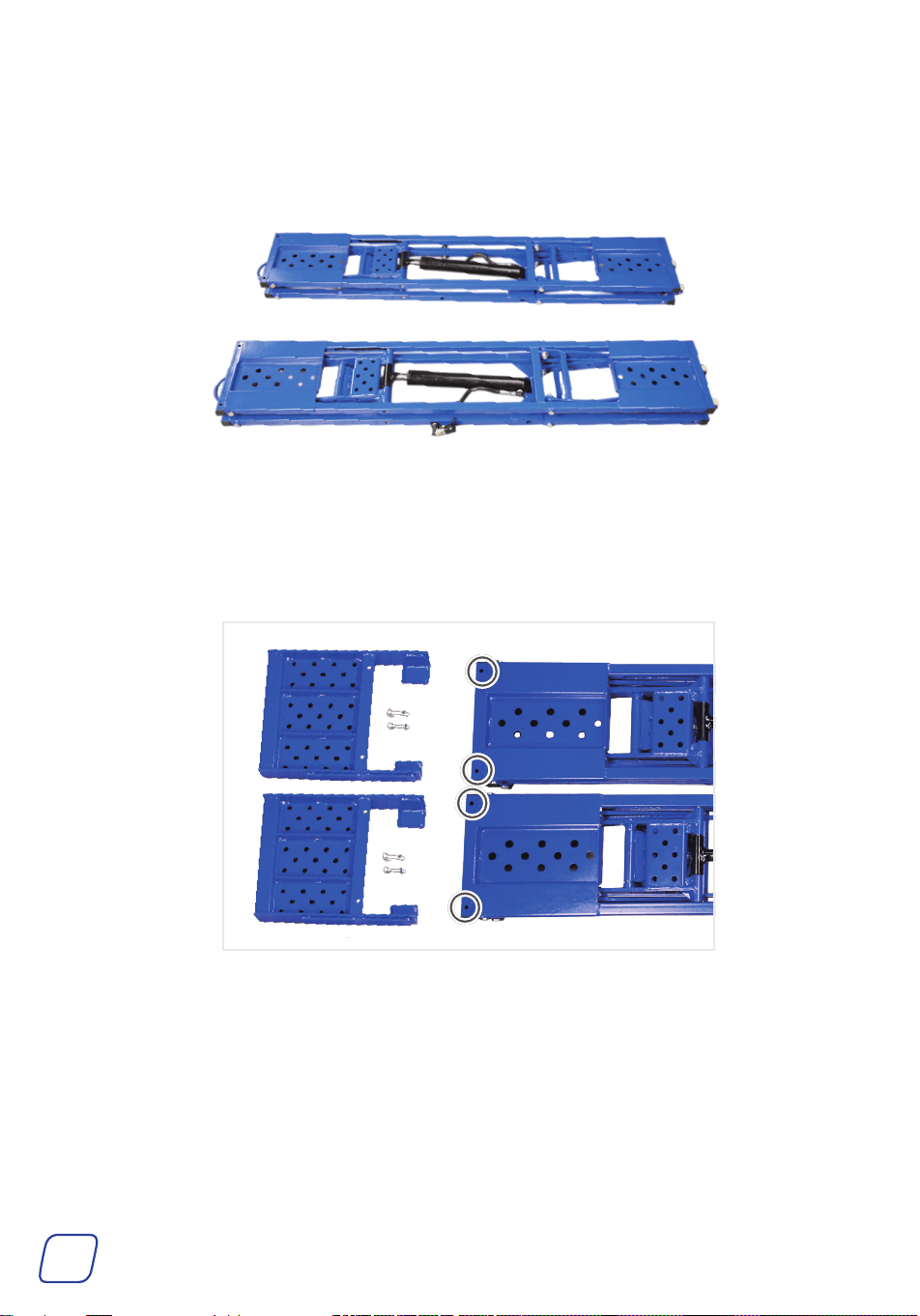
5. Lay the frame assemblies back in the flat position.
Ensure that the hydraulic quick couplers are facing outward.
6. If the vehicle is longer than 6.6 ft (such as vans or pickup trucks), install the extension plates.
7
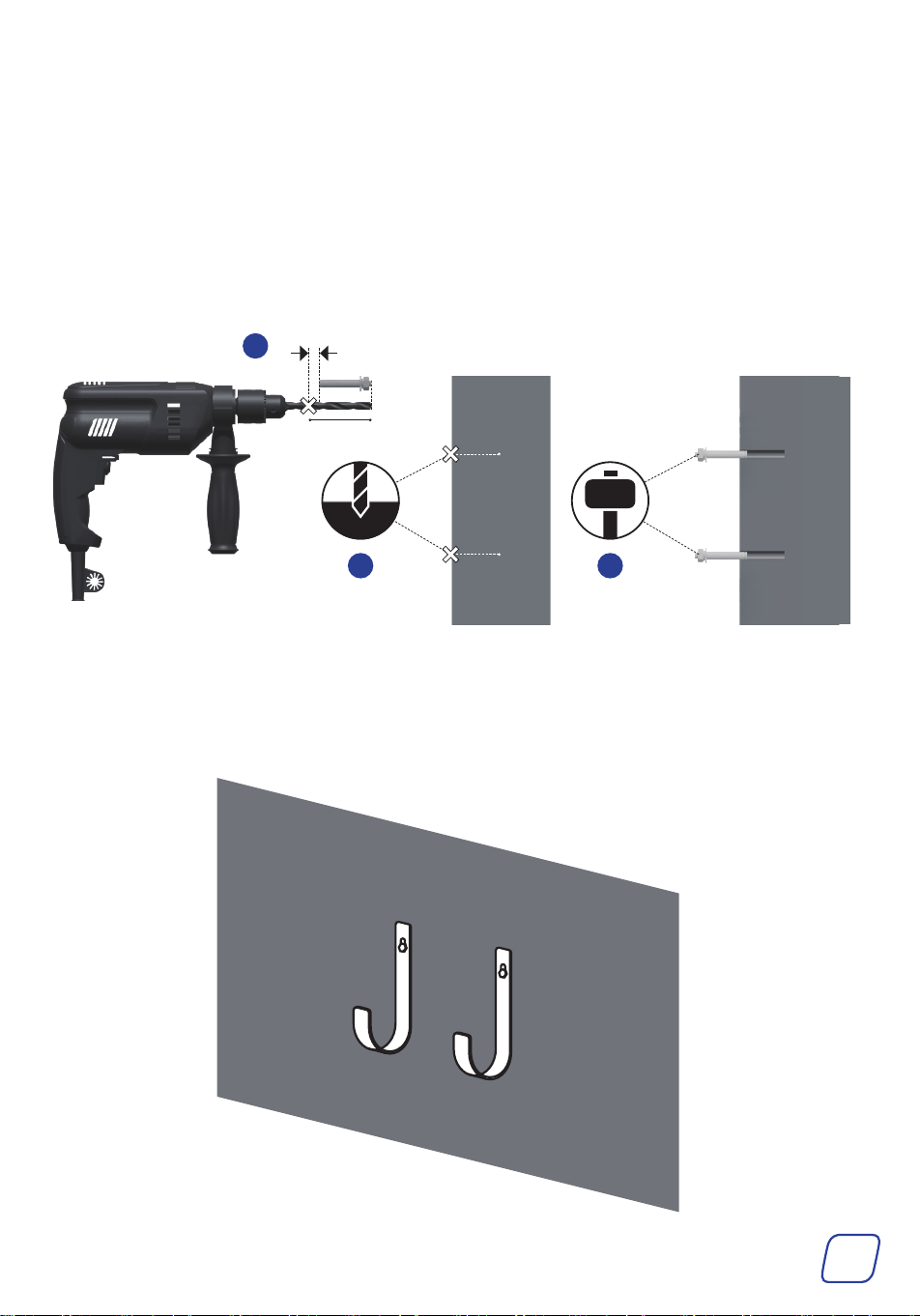
7. (Optional) Install the hooks on the wall.
a. Install a 5/16 ″ (8 mm) drill bit onto the electric drill, then mark a spot on the drill bit
about 0.4 in (1 cm) longer than the length of the expansion bolt sleeve.
b. Drill two holes at the needed locations. Ensure the drill depth reaches the mark on the
bit. Clean out the holes with a fine brush to remove any dust and debris.
c. Hammer the expansion anchors into the holes until the sleeves of the expansion anchors
are entirely embedded in the wall.
d. Remove all nuts and washers from the expansion bolts.
e. Secure the hooks onto the wall with the washers and nuts.
0.4 in (1 cm)
a
b c
8
Operation
Adding the Hydraulic Oil
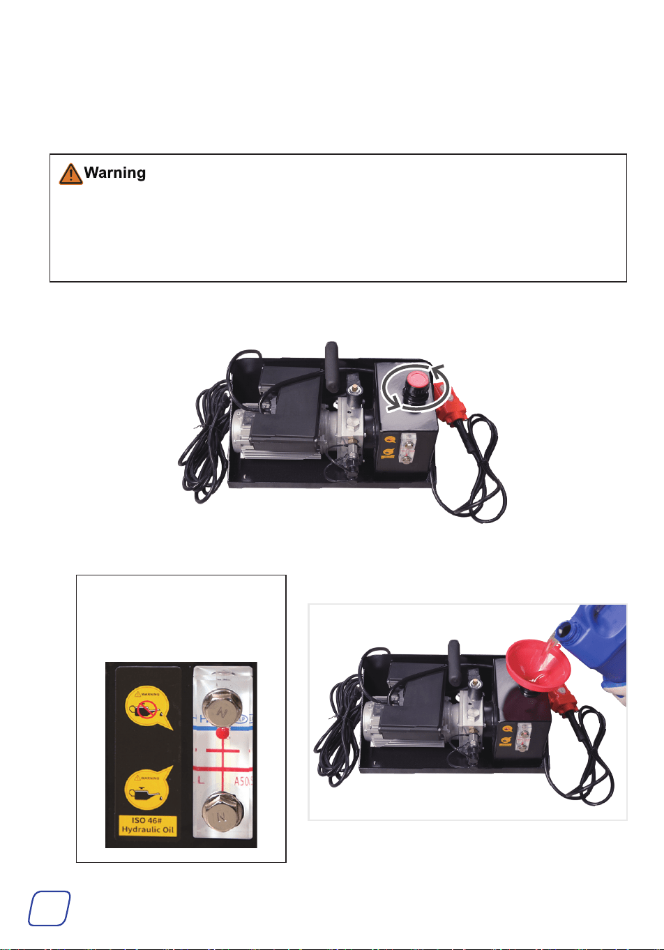
• Use ONLY AW46 hydraulic oil (not included); other oils may cause malfunction or damage.
• DO NOT connect the hydraulic power unit to the power supply until the filling process has
been fully completed.
• This step requires two people to complete.
1. Remove the cap from the hydraulic power unit (S).
2. Place a funnel (not included) at the oil fill port and carefully pour in the hydraulic oil.
Note
The filling capacity is about 1.0
gal (3.8 L). DO NOT fill hydraulic
oil above the blue level line.
9
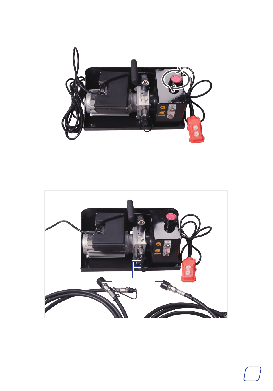
3. Reinstall the cap.
4. Remove the protective covers from the fittings on the power unit and the oil hoses.
Protective Covers
10
5. Connect the oil hose to the fitting and rotate the sleeve to lock, ensuring the groove and lock
ball are misaligned.
Note
You can wrap tape around the joint to ensure a tight seal.
6. Remove the protective cover from the other end of the oil hoses, and place a container (not
included) under the hose fittings.
Groove
Lock Ball
11
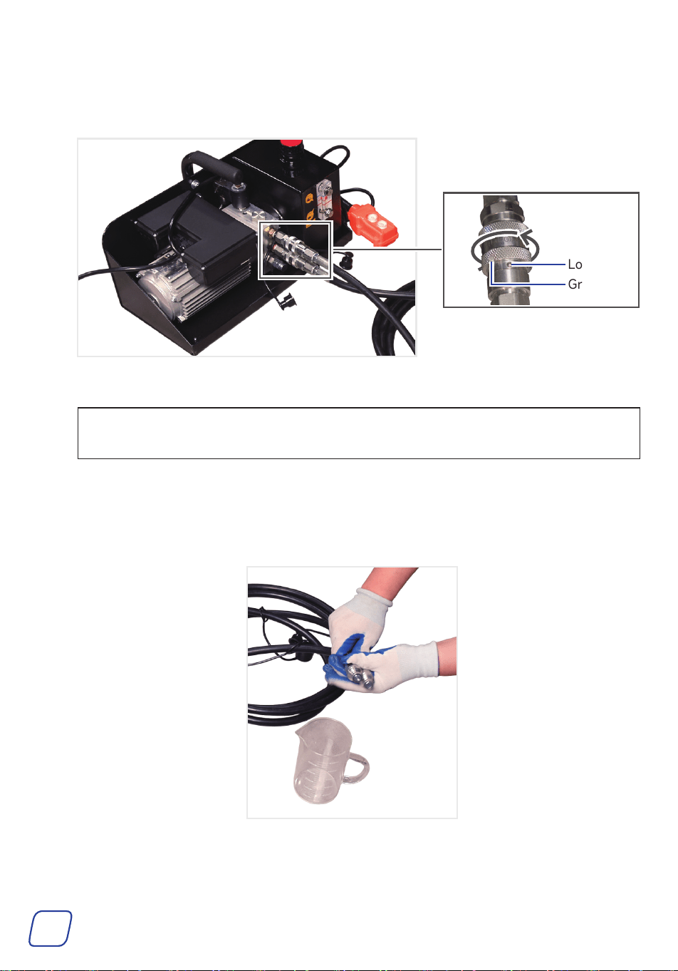
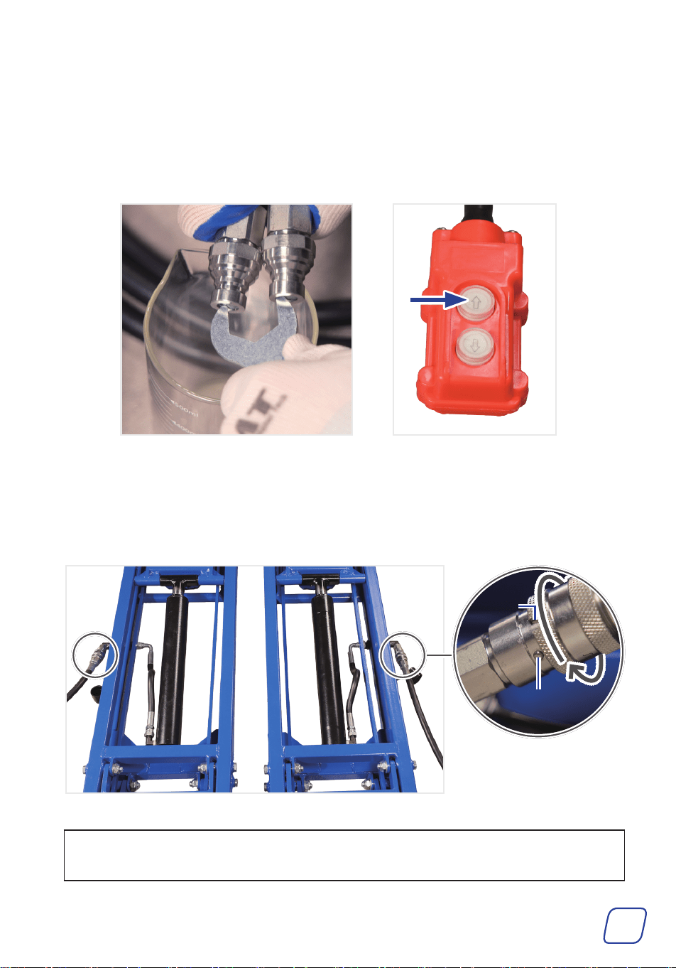
7. Connect the power unit to the power supply.
8. Hold ⇧ on the pendant control while holding the pointed end of a wrench against the hose
fitting.
Continue until the oil flows smoothly without air bubbles. If the hydraulic oil level drops below
the blue line, refill the hydraulic oil.
9. Remove the protective covers from the other ends of the oil hoses and connect them to the
hydraulic quick couplers.
10. Rotate the sleeve to lock, ensuring the groove and lock ball are misaligned.
Note
You can wrap tape around the joint to ensure a tight seal.
Lock Ball
Groove

12
Lifting the Vehicle
• Before lifting, shut off the engine, engage the parking brake (or hand brake),
and chock the remaining wheels. Ensure the vehicle is stationary and the engine has
cooled to room temperature before performing maintenance or adjustments.
• ALWAYS use the correct tools and personal protective equipment (PPE) before performing
any operation. Be extremely careful with possible pinching points, moving parts, or parts
that may suddenly spring out.
• ALWAYS ensure the vehicle is secure when it is supported by a jack or lift.
• For your safety, we recommend completing training before using the tool. Serious injury
could happen due to a lack of training.
• NEVER work under a lifted vehicle unless it is properly supported. ALWAYS use additional
support.
• DO NOT raise the lift without a load, otherwise it may not lower.
• DO NOT remove the vehicle’s tires while lowering the lift to the ground.
1. Raise the lift to 8–12 in (200–300 mm) without load, cycle up and down until both sides are
level.
• If both sides are not level, the vehicle may become unstable and fall from the lift platform,
which could damage the vehicle, damage the lift, and endanger personal safety.
• DO NOT raise the lift to the maximum height without load. If it is accidentally raised to
the top, a load over 77 lb (35 kg) must be placed on the lift before it can be fully lowered.
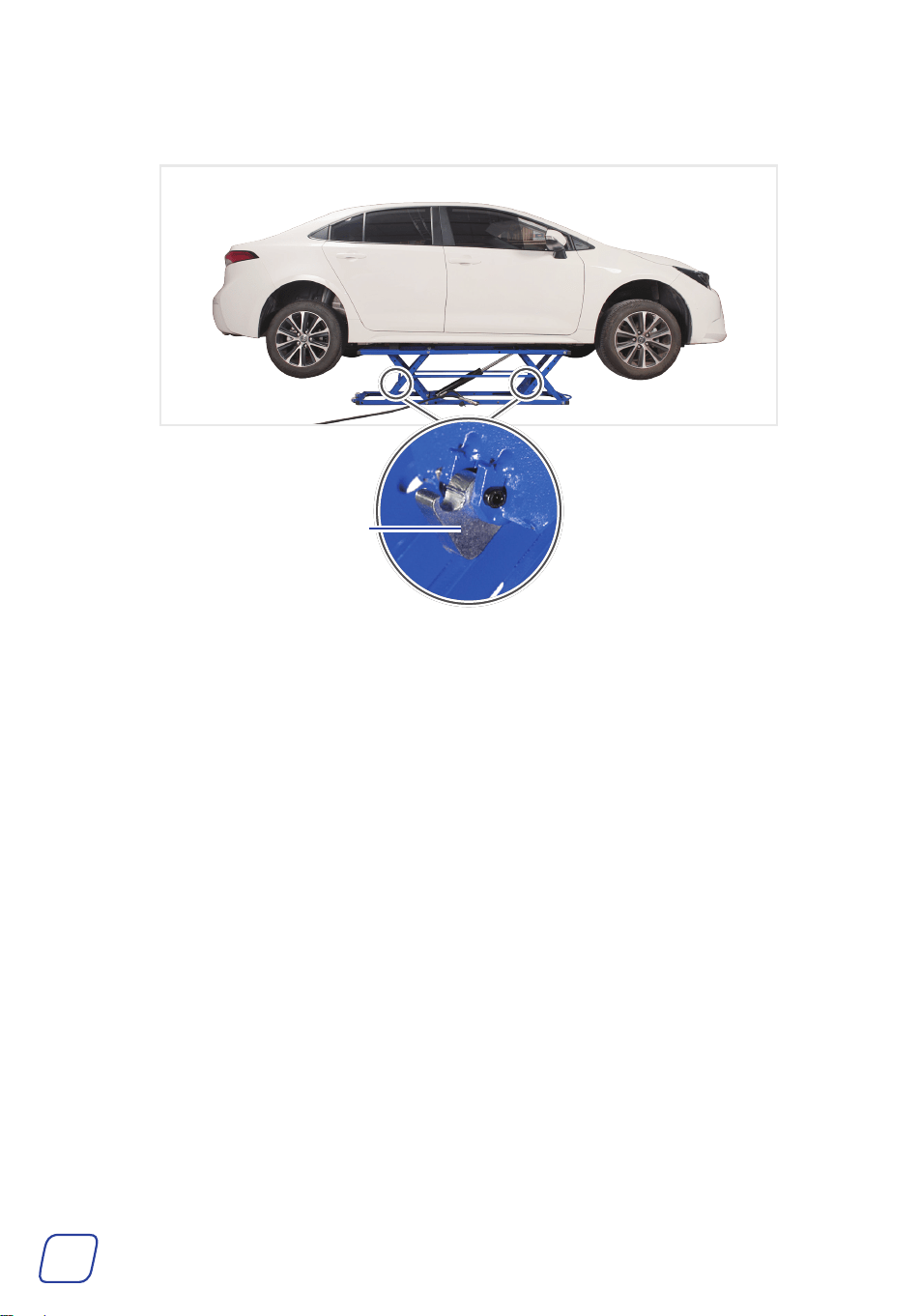
2. Place the lift under the vehicle.
3. Place the rubber blocks (Q or R) in the grooves, aligning them with the center of the support
seams.
Position each rubber block under
the vehicle at the support points
specified by the manufacturer,
and ensure the hydraulic hoses
are not crushed.
Lift
Support
Seam
Square Rubber
Block
13
4. Hold
⇧
on the pendant control until the vehicle reaches the entrance of the slot.
Carefully observe the vehicle’s stability during lifting.
5. After the vehicle reaches the entrance of the slot, hold
⇩
according to the position of the locking
teeth to ensure the lock teeth are stuck in the slot as shown before servicing your vehicle.
• Ensure that the locking teeth enter the slot. The device has 2 slots to achieve 2 safe
locking heights.
• NEVER work under the vehicle without additional jack stands or mechanical supports.
Locking Teeth
Slots
14
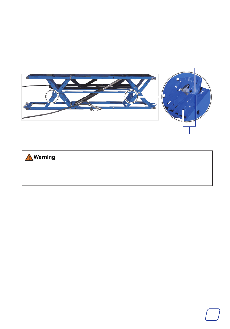
6. After servicing, slightly raise the lift again, and then use a long wrench to push the lock block
down and release the locking teeth.
Lock Block
7. Hold
⇩
on the pendant control until the lift is fully lowered.
8. Remove the lift and blocks from under the vehicle.
Maintenance
• Perform a thorough inspection of the product at least once a year.
• Check for smooth movement and secure connections before each use. Never use this tool if
any part is found to be loose, bound, worn, or damaged. Tighten, lubricate, repair, or replace
all such components before further use. Only use identical parts for replacement.
• Clean the components of this kit after each use. Do not use caustic chemicals or harsh
abrasives.
• If the tool is not going to be used for an extended period, clean and lubricate it and store it
in a cool, dry place inaccessible to children. If hooks are installed, the lift can be stored by
hanging it on the wall.
15
Troubleshooting
Problems Usual Solutions
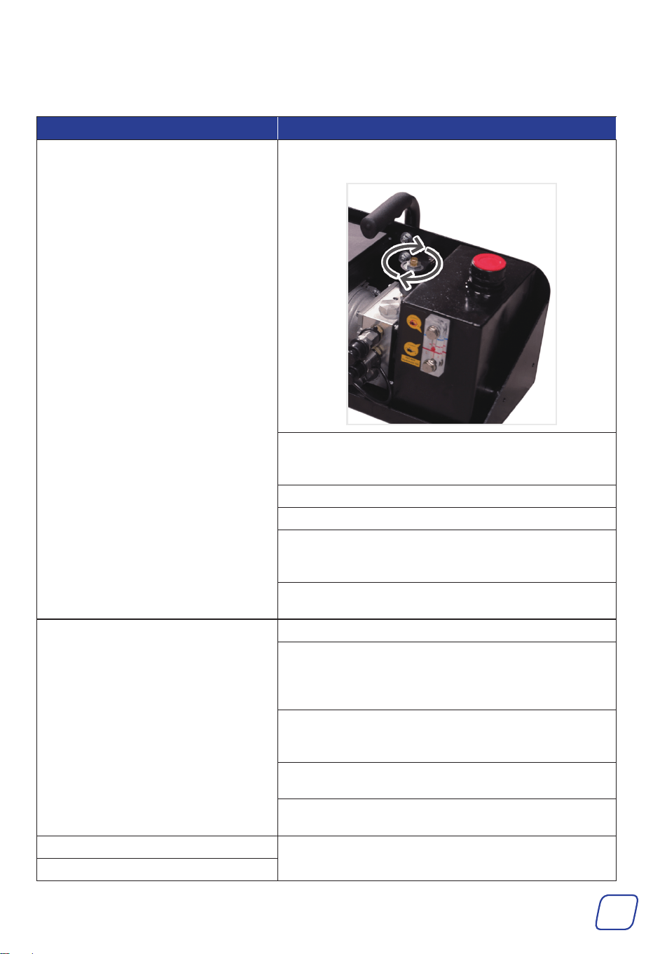
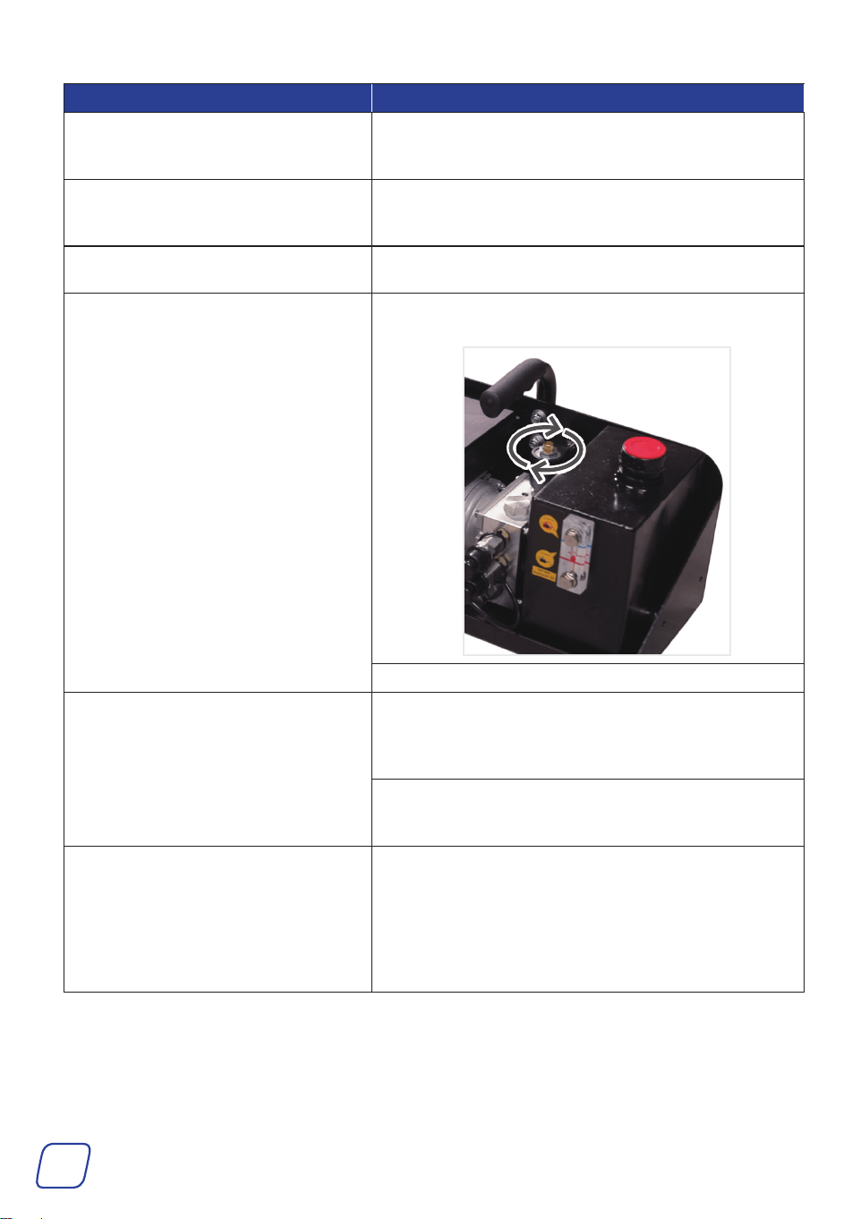
The lift fails to raise the vehicle.
Ensure the solenoid unloading valve is in the closed
state. If you can’t turn it clockwise, it is closed.
Check whether the oil pump makes an operating
sound. If there is no sound, contact a qualified
technician for service.
Ensure the oil hoses are not kinked or leaking.
Ensure there is sufficient hydraulic oil in the tank.
Ensure the power unit is properly connected to the
power supply and the voltage is neither too low nor
too high.
Refer to step 8 of Adding the Hydraulic Oil on
Page 11 to bleed the oil hoses.
The lift fails to lower the vehicle.
Make sure the lift is not unloaded.
Contact a qualified technician to check whether the
hose fittings, valve, and other components are blocked
by foreign matter. If so, clean them thoroughly and
replace the supplied O-rings and filter rings
Check whether the oil pump makes an operating
sound. If there is no sound, contact a qualified
technician for service.
Contact a qualified technician to check whether the
solenoid unloading valve is operating properly.
Ensure that the locking teeth mechanism is fully
released.
The pump has no pressure.
Contact a qualified service technician to repair the
pump.
The pump cannot maintain pressure.
16
Problems Usual Solutions
The lift is stuck at the highest point
and cannot be lowered when there is
no load.
Place a heavy object on the lift and lower it.
The hydraulic oil is contaminated.
Disconnect power and lower the lift completely.
Remove the cap and drain all the oil. Refill the tank
using 46# hydraulic oil.
The lift generates abnormal noise
during operation.
Apply grease to the specified lubrication points.
The lift slowly lowers without control.
Ensure the solenoid unloading valve is in the closed
state. If you can’t turn it clockwise, it is closed.
Ensure the locking teeth mechanism is locked.
Quick couplers become harder to
connect.
The hydraulic system pressure builds up. To prevent
this, after the frame reaches the ground, hold
⇩
on the
pendant control for a few seconds to allow as much
oil as possible to return to the tank.
If pressure builds up excessively and quick couplers
cannot be connected, contact a qualified service
technician to repair the lift.
The lift raises unevenly on both sides.
With no load, raise the lift frame to 8–12 in (200–300
mm) and cycle it up and down several times until both
sides are level. If the sides are still not level, bleed the
pump station again and then repeat the procedure.
If the problem persists, the flow divider valve may be
blocked or damaged. Contact a qualified technician for
cleaning or repair.

17
Disposal
Electrical products should not be disposed of with household products. In the EU
and UK, according to the European Directive 2012/19/EU for the disposal of electrical
and electronic equipment and its implementation in national laws, used electrical
products must be collected separately and disposed of at the collection points
provided for this purpose. Locations in Australia, Canada, and the United States may
have similar regulations. Contact your local authorities or dealer for disposal and
recycling advice.


We care about your experience!
♥
https://orionmotortech.com/
We truly hope our product brings you joy and convenience.
If you have any questions or need assistance, please don’t hesitate to reach out.
We’re always happy to help!
Simply fill out the form below, take a photo of it (along with any relevant photos or videos if
needed), and email it to us. Our service team will respond within 24 hours.
Platform
□ Amazon □ eBay □ Walmart □ Wayfair □ Other: (please specify)
Order Information
Subject of Inquiry
Your satisfaction means everything to us. :)
Order No.:
Product:
Purchase Date:
Your Name:
Email:
User Manual
Rev. 28 Sept. 2025