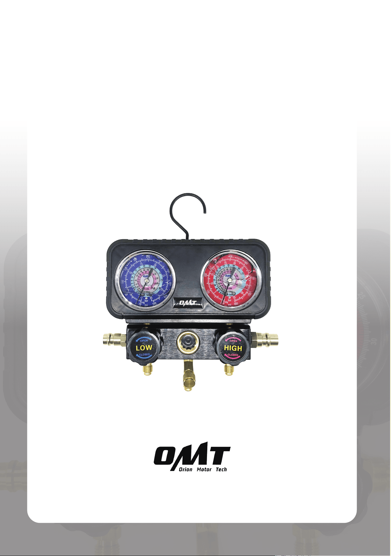
3-Valve Manifold Gauge Set
User Manual
Read Carefully Before Use
Keep for Future Reference
UM-DMG-0021-V2

Disclaimer
Read this disclaimer completely and carefully before proceeding with the rest of the manual content.
1.
Product Modications
Any modications or alterations to Orion Motor Tech (OMT) products void any warranties
and may result in damage or injury. OMT shall not be liable for any damages resulting from
such modications or alterations.
2.
Compliance with Laws
Customers shall be liable for ensuring that the use of OMT products complies with
all applicable laws and regulations in their respective jurisdictions. OMT assumes no
responsibility for any violations of laws or regulations resulting from the use of OMT
products.
3.
Correct Use
Always use OMT products only as directed in the accompanying manuals. Failure to follow
instructions may result in injury or damage.
Always ensure the assembly, installation, operation, maintenance, or repair of OMT
products is carried out by a competent person.
Always make maintenance regularly throughout OMT products’ lifecycles; you have the
liability to keep the products operating as intended.
Always wear appropriate protective gear.
4.
Third-Party Products
OMT shall not be liable for any damages or losses resulting from the use of third-party
products in conjunction with OMT products. Customers shall refer to the third-party's
guidelines or/and warranties (if any) for any third-party products used.
5.
Limitation of Liability
OMT shall not be liable for any direct, indirect, punitive, incidental, special, or consequential
damages to property or life, whatsoever arising out of or connected with the use or misuse
of OMT products. In no event shall OMT’s liability exceed the value of the products sold.
6. Warranty
Refer to the sales page for warranty information.
This disclaimer states the entire obligation of OMT with respect to OMT products. If any part
of this disclaimer is determined to be void, invalid, unenforceable, or illegal, including but not
limited to the warranty disclaimers, liability disclaimers, and liability limitations set forth above,
the invalid or unenforceable provision will be deemed superseded by a valid and enforceable
provision that most closely matches the intent of the original provision and the remainder of the
agreement shall remain in full force and eect.

Contents
1 Safety Information ......................................................................................... 1
2 Specications ................................................................................................ 2
3 Package List .................................................................................................. 3
4 Product Diagram ........................................................................................... 5
5 Preparation .................................................................................................... 6
6 Initial setup of AC System ............................................................................ 7
6.1 Connecting the Hoses to the Gauge ......................................................................... 7
6.2 Connecting the Quick Couplers to the Pressure Hoses ............................................ 8
6.3 Connecting the Quick Couplers to Your A/C System ................................................ 9
7 AC System Operation ................................................................................... 11
7.1 Performing Leakage Test .......................................................................................... 11
7.2 Evacuation ................................................................................................................ 13
7.3 Charging .................................................................................................................... 15
8 Initial Setup of HVAC System ....................................................................... 19
9 Operation of HVAC System .......................................................................... 20
9.1 Performing Leakage Test .......................................................................................... 20
9.2 Evacuation ................................................................................................................ 20
9.3 Charging .................................................................................................................... 20
10 Maintenance ................................................................................................. 24
11 Troubleshooting ........................................................................................... 24
1
1 Safety Information
• Read these instructions carefully before use and s tore this manual for future reference. Include this
manual with this device if ever given or sold to a third party. Failure to follow these instructions may lead
to serious property damage and severe personal injury.
•
ALWAYS
wear personal protective equipment such as a dust mask, goggles, and work gloves. Work in a
well-ventilated area, as refrigerants can irritate your eyes, nose, throat, and skin or cause frostbite, heart
arrhythmia, unconsciousness, and even death. Additionally, operating your vehicle in an enclosed space
may result in carbon monoxide poisoning and other problems.
• If you begin to develop symptoms such as headaches, dizziness, or nausea while using this product,
turn o your vehicle and get fresh air
IMM EDI ATELY
.
DO NOT
resume work until the vehicle is in a well-
ventilated area.
•
ON LY
use with
R1234yf
,
R134a
,
and
R410a
refrigerant and their matching vehicle A/C systems. It
should
NOT
be used with other refrigerants or home A/C systems, which can damage this product and
your property.
• Use
EXTREME
caution when disconnecting the hoses after use as they may still contain some
refrigerant under pressure.
•
ON LY
use the coupler marked
HIGH
on the
HIGH-PRESSURE
service port.
ON LY
use the coupler
marked
LOW
on the
LOW-PRESSURE
port. Interchanging them may result in severe property damage
and serious personal injuries.
• Turn your air-conditioning (A/C) or HAVC system o before evacuation.
•
DO NOT
allow children or persons with compromised physical or mental capabilities to use this product.
Keep children, bystanders, and pets away during use.
• Stay alert, watch what you are doing, and use common sense when using this product.
DO NOT
use it
while you are tired or under the inuence of drugs, alcohol, or any medication.
•
ALWAYS
perform leak tests for this product and your A/C or HAVC system
BEFORE
charging. Fix any
issues quickly and ensure that everything is leak-free before continuing on your way.
• Keep your work site clean and well-lit. Cluttered and dark work areas invite accidents.
• For best results, keep the kit clean and dry. Remove any uid, oil, or grease before and after work.
•
DO NOT
leave this product unattended during use.
• In case of an accident or injury, have a rst aid kit and a communication device (e.g., a phone) readily
available. Know the location of emergency medical facilities.
• Maintain this product. Check for misalignment, binding, wear, or other damage before use. If any damage
is detected, repair or replace the problematic components before further use. In a large shop, mark such
tools as “
DO NOT USE
” until they have been repaired or replaced.
ON LY
replace components with
identical or authorized parts.
• Machinery repair is inherently dangerous. This manual and the separate machinery service manual
cannot cover all possible situations.
ALWAYS
exercise discretion and good judgment. Seek training if
needed.
2
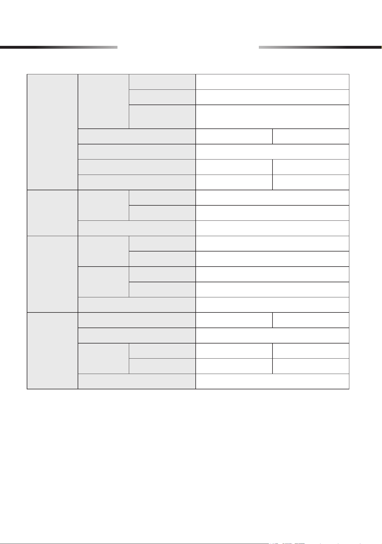
2 Specications
Hoses
Colors
Low-Pressure
Blue
High-Pressure
Red
Evacuation/
Charging
Yellow
Total Length
5 ft. 1.5 m
Thread Dia.
1/4 in.
Working Pressure
600 psi 41 bar
Burst Pressure
3000 psi 206 bar
Quick
Couplers
Colors
Low-Pressure
Blue
High-Pressure
Red
Thread Dia.
1/4 in.
Refrigerant
Can Taps
Colors
R1234yf
Blue
R134a
Red
Thread Dia.
Male Outlet
1/4 in.
Female Inlet
1/2 in.
Compatible Can Type
Self-Sealing
Gauge Set
Overall Dimensions
7.3×6.3×2.4 (in.) 18.5×16×6 (cm)
Port Thread Dia.
1/4 in.
Pressure
Capacity
Low-Pressure
−15* to 500 (psi) −1 to 35 (bar)
High-Pressure
−15* to 800 (psi) −1 to 55 (bar)
Acceptable Refrigerants
R1234yf, R134a, and R410a
* Note: Negative pressure readings are typically measured in inches of mercury (inHg), which
roughly equate to half the value in pounds per square inch (psi) or 1.3% of the value in
centimeters of mercury (cmHg), kilograms per square centimeter (kg/cm²), or bars.
3
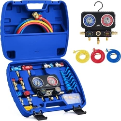
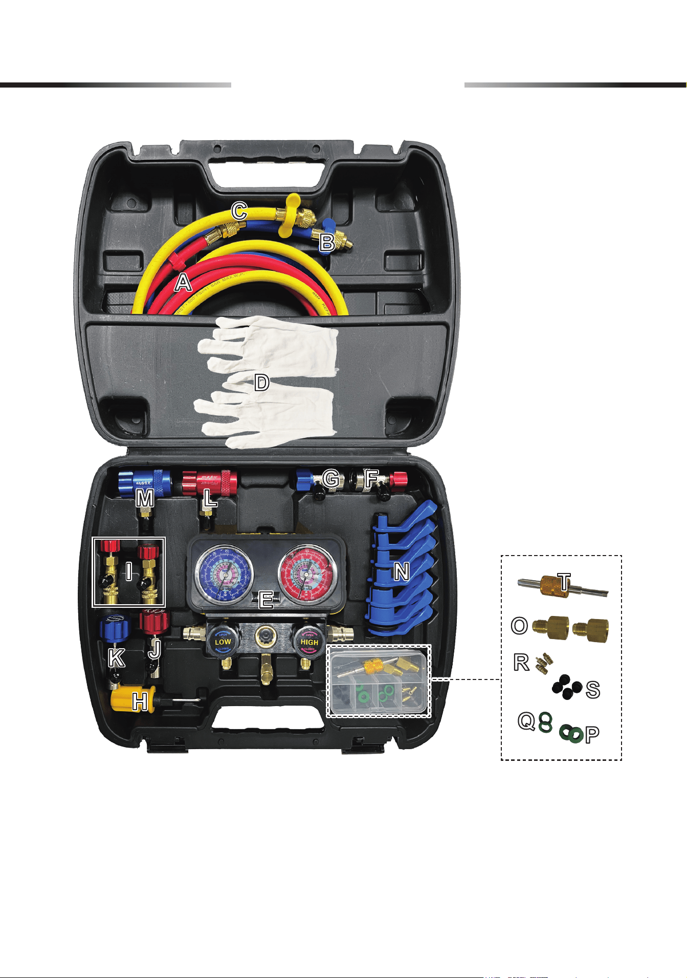
3 Package List
4
3 Package List
Item Name Qty.
A
High-Pressure Hose (Red) 1
B
Low-Pressure Hose (Blue) 1
C
Evacuation/Charging Hose (Yellow) 1
D
Work Gloves 1 Pair
E
Gauge Set 1
F
High-Pressure Quick Coupler (Red, for
R134a
refrigerant) 1
G
Low-Pressure Quick Coupler (Blue, for
R134a
refrigerant) 1
H
Dual-Purpose Screwdriver 1
I
R410A Safety Valves 2
J
Self-Sealing Can Tap (Red, for
R134a
refrigerant) 1
K
Self-Sealing Can Tap (Blue, for
R1234yf
refrigerant) 1
L
High-Pressure Quick Coupler (Red, for
R1234yf
refrigerant) 1
M
Low-Pressure Quick Coupler (Blue, for
R1234yf
refrigerant) 1
N
Pipe Disassembly Tools (7/8", 3/4", 5/8", 1/2", 3/8", 5/16", 1/4") 7
O
1/4" Male to 1/2" Female Adapters (Counterclockwise marked
LH
) 2
P
O-Rings 2
Q
Flat Gaskets 2
R
Copper Cores 3
S
Hose Gaskets 4
T
Valve Core Wrench 1
Not Included but Helpful:
• Micron Gauge
• Vacuum Pump
• Refrigerant Can
• Nitrogen Source
• Dust Masks
• Goggles
• Tape
• Leak Detector
• Soapy Water
5
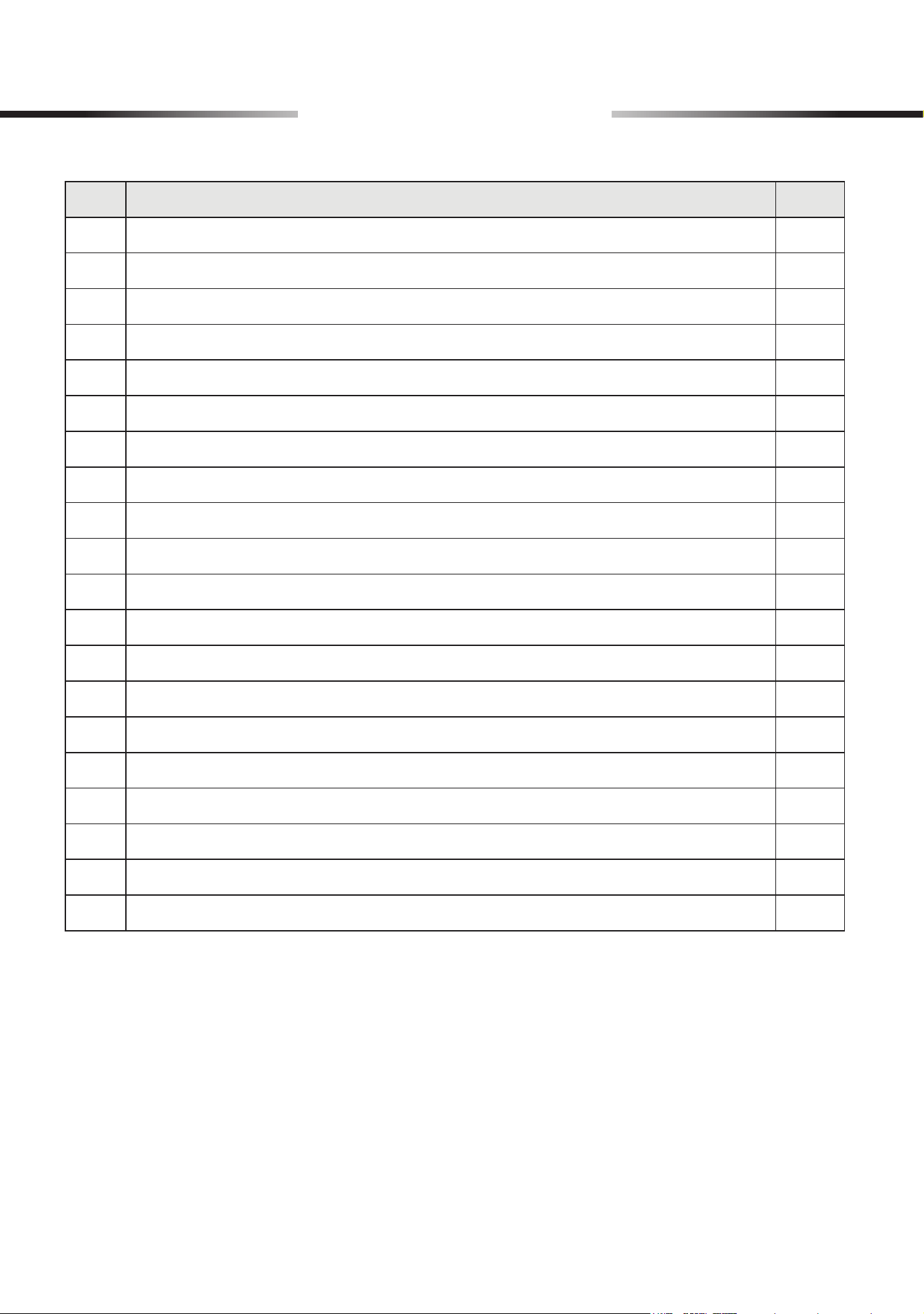
4 Product Diagram
High-Pressure GaugeLow-Pressure Gauge
Side Holder
Low-Pressure Valve Knob
Low-Pressure Valve Port
Evacuation/Charging Port
High-Pressure Valve Knob
Viewing Window
High-Pressure Valve Port
Unloading Valve
For R134a SystemsFor R1234yf Systems
6
5 Preparation
Refrigerant can irritate your eyes, nose, throat, and skin or cause frostbite, heart arrhythmia,
unconsciousness, and
EVEN
death.
Using this product with missing, broken, nonidentical, or unauthorized parts
WILL
pose a
series of safety hazards.
Clearing Your Work Area
Make sure the work area meets the following conditions:
• No children, bystanders, or pets
• Clean and clear of any clutter or dirt that may aect operation or pose safety hazards
• Well-lit and ventilated but adequately protected from the elements
• Free of explosives and sources of heat such as recrackers and open ames
Putting on Proper PPE
Hand, breathing, and eye protection are required and should meet the standards by ANSI (American
National Standards Institute) or OSHA (Occupational Safety and Health Administration).
The recommended ones include:
• Work Gloves (D)
• Dust Masks
• Goggles
Checking the Product
After unpacking, check that all items are included and undamaged.
If necessary, ask your local dealer or contractor for new identical replacements.
Familiarizing Yourself with Your HAVC or A/C Systems
For optimal safety, know your HAVC or A/C system well and take sucient training before using this
product.
Failures and accidents could happen due to a lack of training.
7
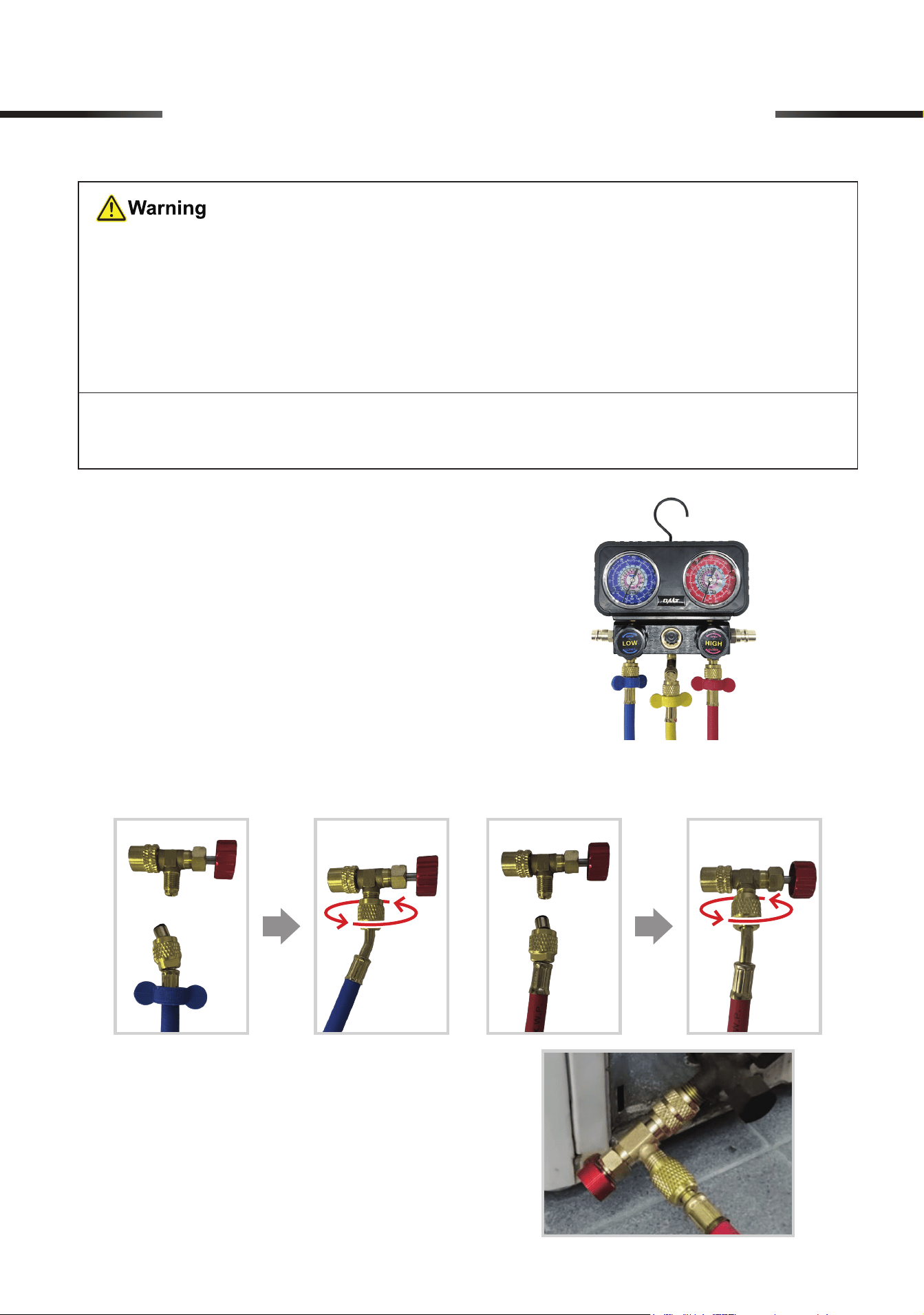
6 Initial setup of AC System
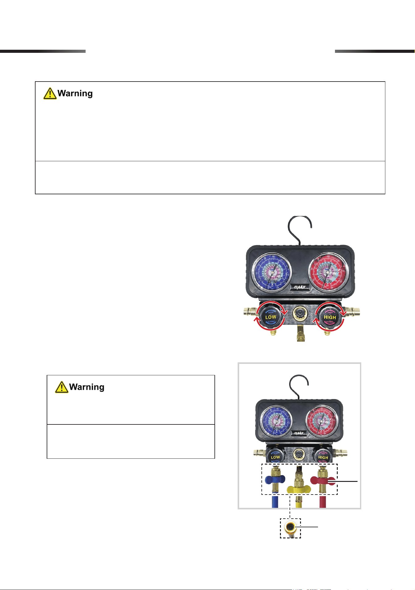
6.1 Connecting the Hoses to the Gauge
1. Turn the knobs on the gauge set (E) completely
clockwise, FULLY closing its low-pressure (LP)
and high-pressure (HP) valves.
2. Unscrew the valve port caps under the knobs,
connect the provided hoses to the corresponding
ports by hand, and tighten the connections by
hand using the hoses’ locking nuts. The wrench
through the hose helps tighten the locking nut.
• Connect the blue LP hose (B) to the port
below the LP knob (LOW).
• Connect the red HP hose (A) to the port
below the HP knob (HIGH).
• Connect the yellow evacuation/charging
(E/C) hose (C) to the remaining port in the
middle of the gauge.
• Make sure your surroundings
ARE
safe for using this product.
Avoid operating in crowded, dark, or cluttered areas. Ensure
NO
explosives or ignition
sources nearby.
• Be sure that
ALL
connections
ARE
tightly secured.
Note: Wrapping the threads with sealing tape (not included) before making the connection
helps prevent leaks.
DO NOT
mix up the three hoses, as they
are
NOT
interchangeable.
Note:
Use the hose ends
WITHOUT
copper cores inside.
Wrench
Locking Nut
8
6 Initial setup of AC System
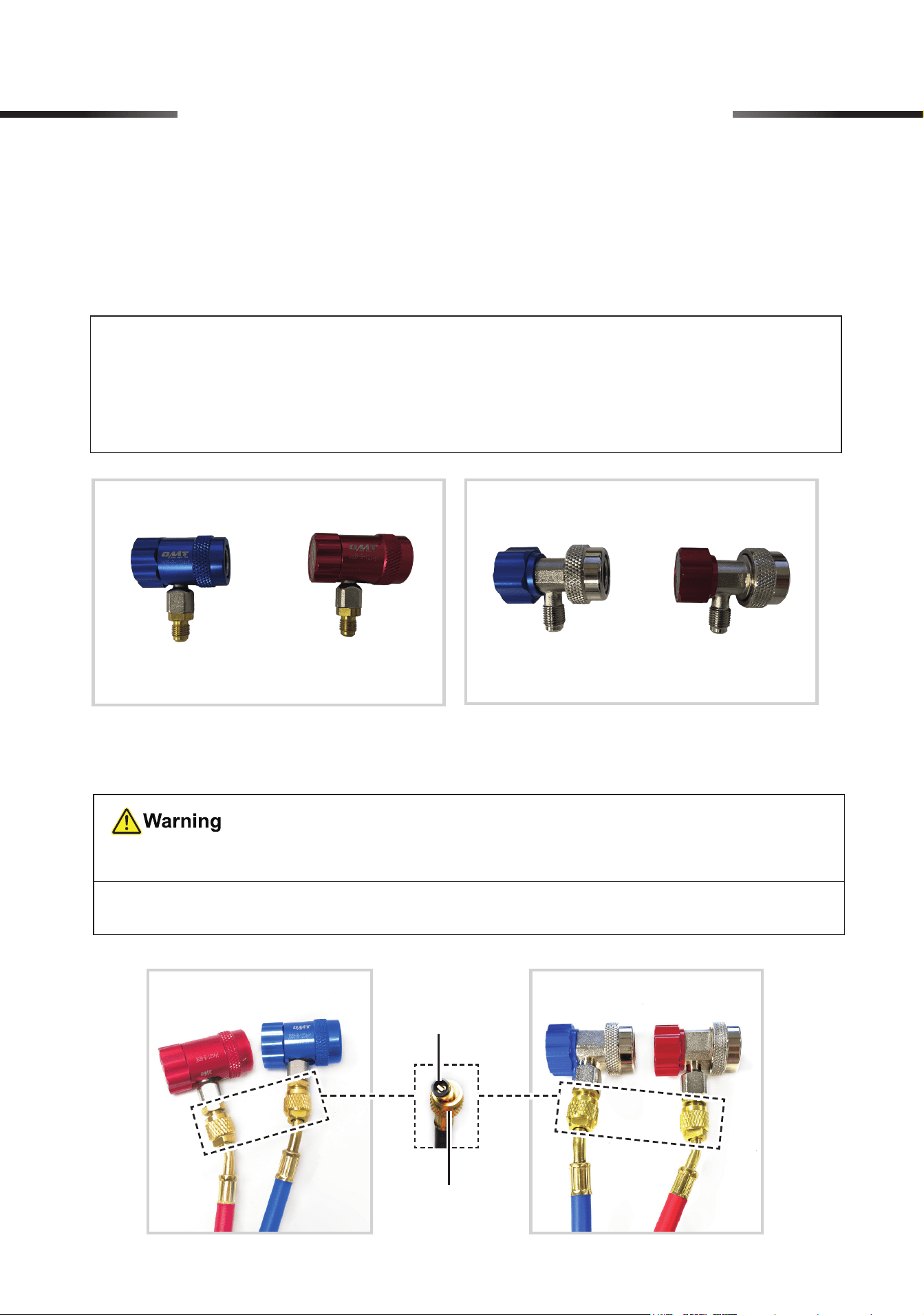
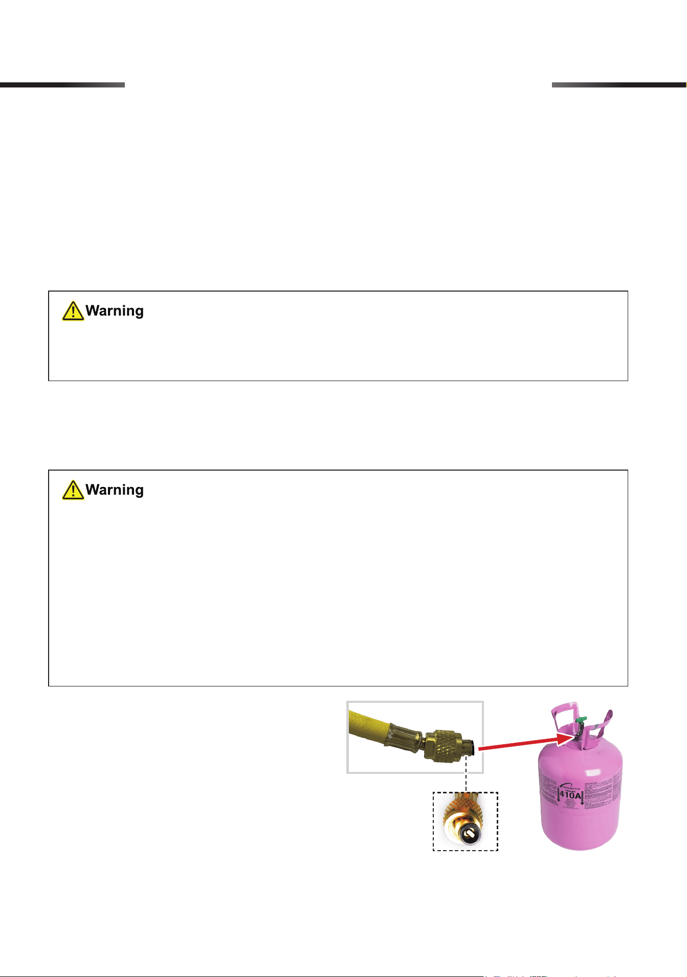
6.2 Connecting the Quick Couplers to the Pressure Hoses
1. Select the quick couplers appropriate for your system.
• Use the couplers marked R1234yf (L and M) for R1234yf refrigerant systems.
• Use the couplers marked R134a (F and G) for R134a refrigerant systems.
2. Connect the blue and red hoses to their identically colored quick couplers, and tighten the
connections by hand using the hoses’ locking nuts.
For R134a SystemsFor R1234yf Systems
DO NOT
mix up these hoses and couplers, as they are
NOT
interchangeable.
Note:
Use the hose ends
WITH
copper cores inside.
Note:
• If your system uses R404a refrigerant, prepare couplers compatible with your system
and hoses.
• O N LY R1234yf, R134a, and R410a are compatible with the gauge set.
Copper Core
Locking Nut
For R134a SystemsFor R1234yf Systems
9
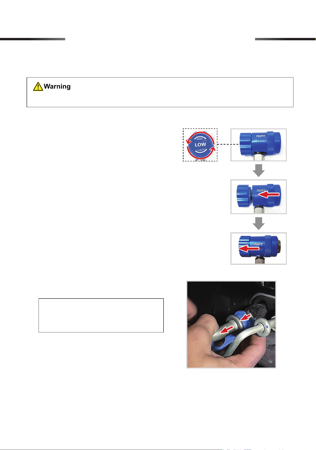
6.3 Connecting the Quick Couplers to Your A/C System
1. Hang up the gauge using its hook to ensure
optimal safety, stability, and accessibility during
use.
2. Turn the blue and red quick couplers’ knobs
completely counterclockwise.
3. Hold one coupler and pull back the sleeve to the
knob.
(Example: R1234yf LP Coupler)
Ensure that your A/C system has been turned o.
6 Initial setup of AC System
4. Push the coupler onto its matching service port
of your AC system.
Note:
You can use the included pipe
disassembly tools (N) to disassemble the
AC system piping as needed.
a. Select the right-sized pipe disassembly
tool (N).
b. Place the tool on one side of the pipe
connection.
c. Press down the top of the tool with one
hand to keep it steady.
d. Use your other hand to slowly rotate the
pipe and pull it outward.
5. Release the sleeve to secure the connection. GENTLY pull the coupler to verify the connection’s
security.
10
6. Repeat steps 3−5 for connecting the other
coupler to the A/C system.
• DO NOT connect the two couplers
to the INCORRECT service ports
to prevent system malfunctions and
safety hazards.
• ALWAYS refer to the instructions
and guidelines provided by the
manufacturer of your A/C system for
proper installation procedures.
(Example: R1234yf LP Coupler)
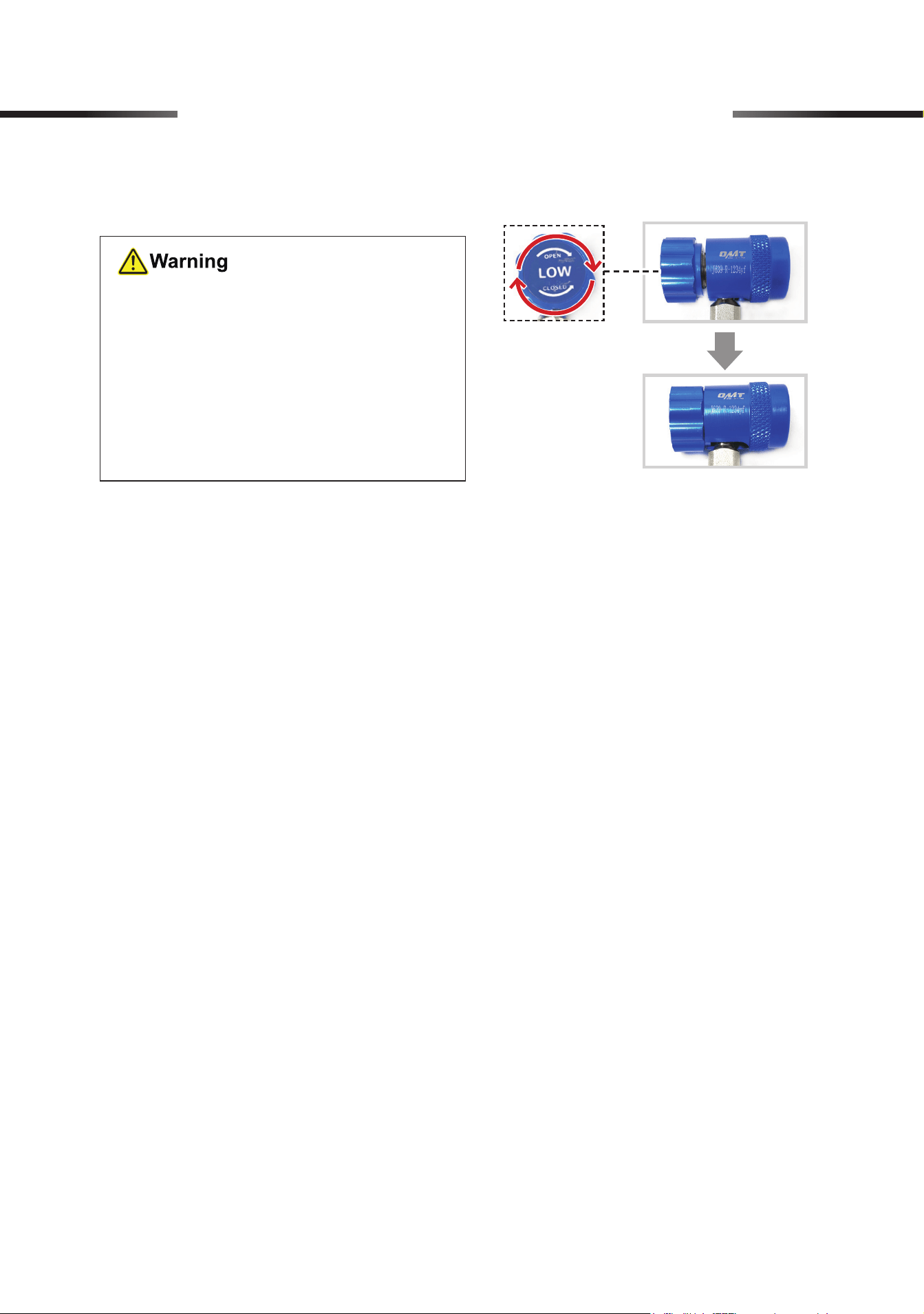
6 Initial setup of AC System
7. Turn the blue and red quick couplers’ knobs completely clockwise.
11
7 AC System Operation
You can evacuate your A/C system, and then charge it with refrigerant.
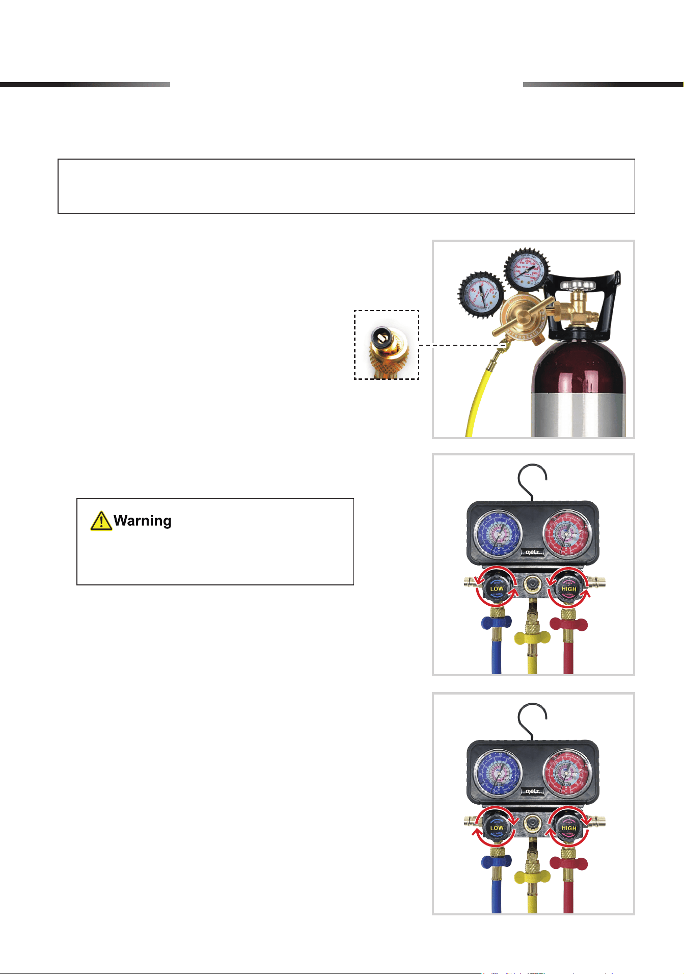
2. Turn on the nitrogen source and set the pressure
value.
3. Open the LP and HP valves by turning their
knobs SLOWLY counterclockwise.
4. Once the gauge set indicates the same pressure
values as the nitrogen source, close the LP and
HP valves by turning their knobs COMPLETELY
clockwise.
7.1 Performing Leakage Test
1. Connect the yellow hose WITH a copper core
inside to a nitrogen source (not included).
The pressure value must NOT exceed your
A/C system’s maximum pressure.
Note: Wrapping the threads with tape (not included) before making the connection helps
prevent leaks.
12
5. It is recommended to observe the gauge set for about 15 to 30 minutes to ensure that the
pressure readings remain stable.
If the readings have a signicant drop, leakage may exist in the system. Use a leak detector (not
included) to detect leakage and apply soapy water (not included) to locate leakage. Repair or
replace any detected loose joints or worn parts before further use.
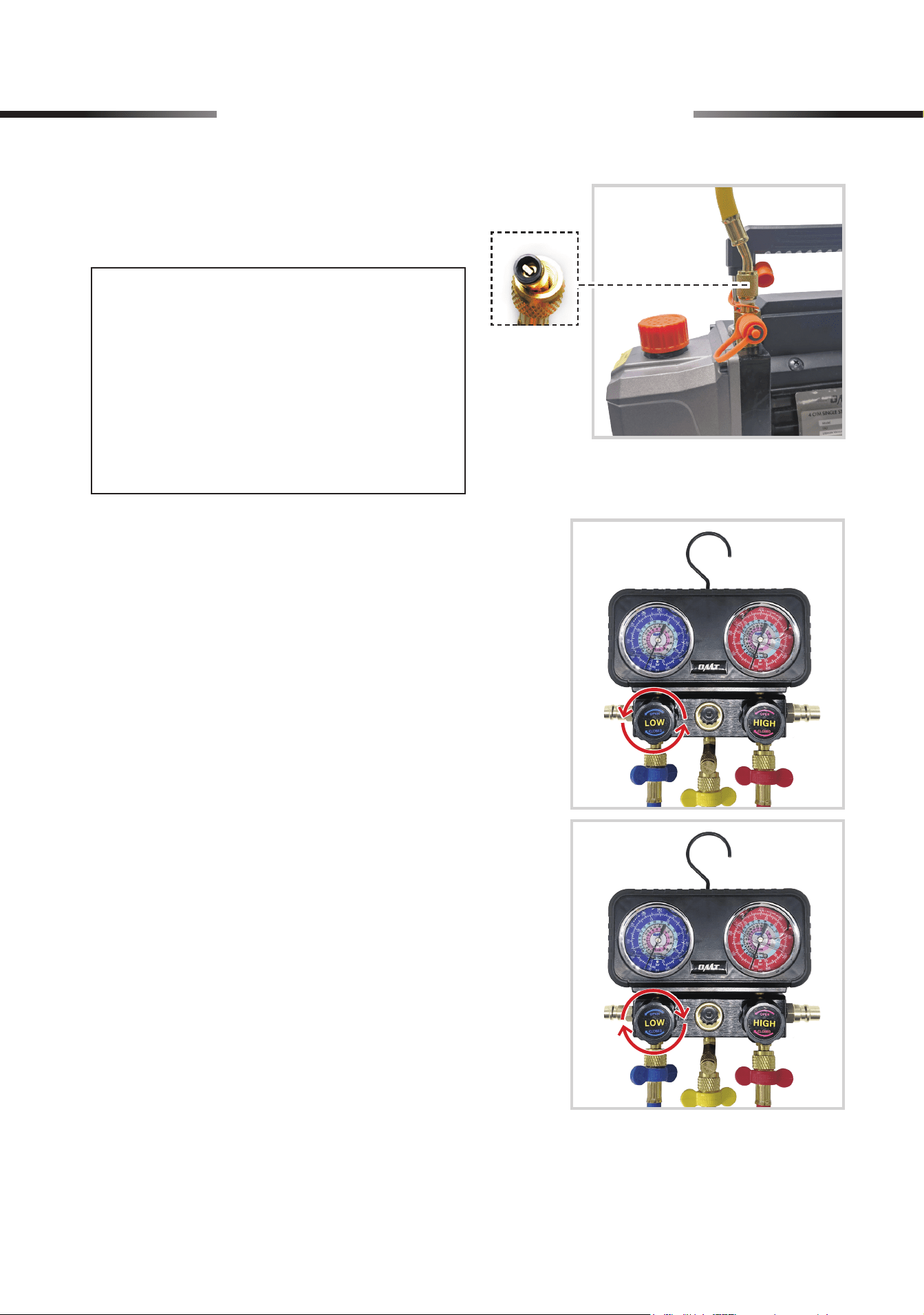
6. If the pressure readings remain stable and there
is no leakage, turn o the nitrogen source and
disconnect the yellow EC hose from the nitrogen
source.
7. Open the LP valve by turning its knob (LOW)
SLOW LY counterclockwise to release the
nitrogen gas.
7 AC System Operation
13
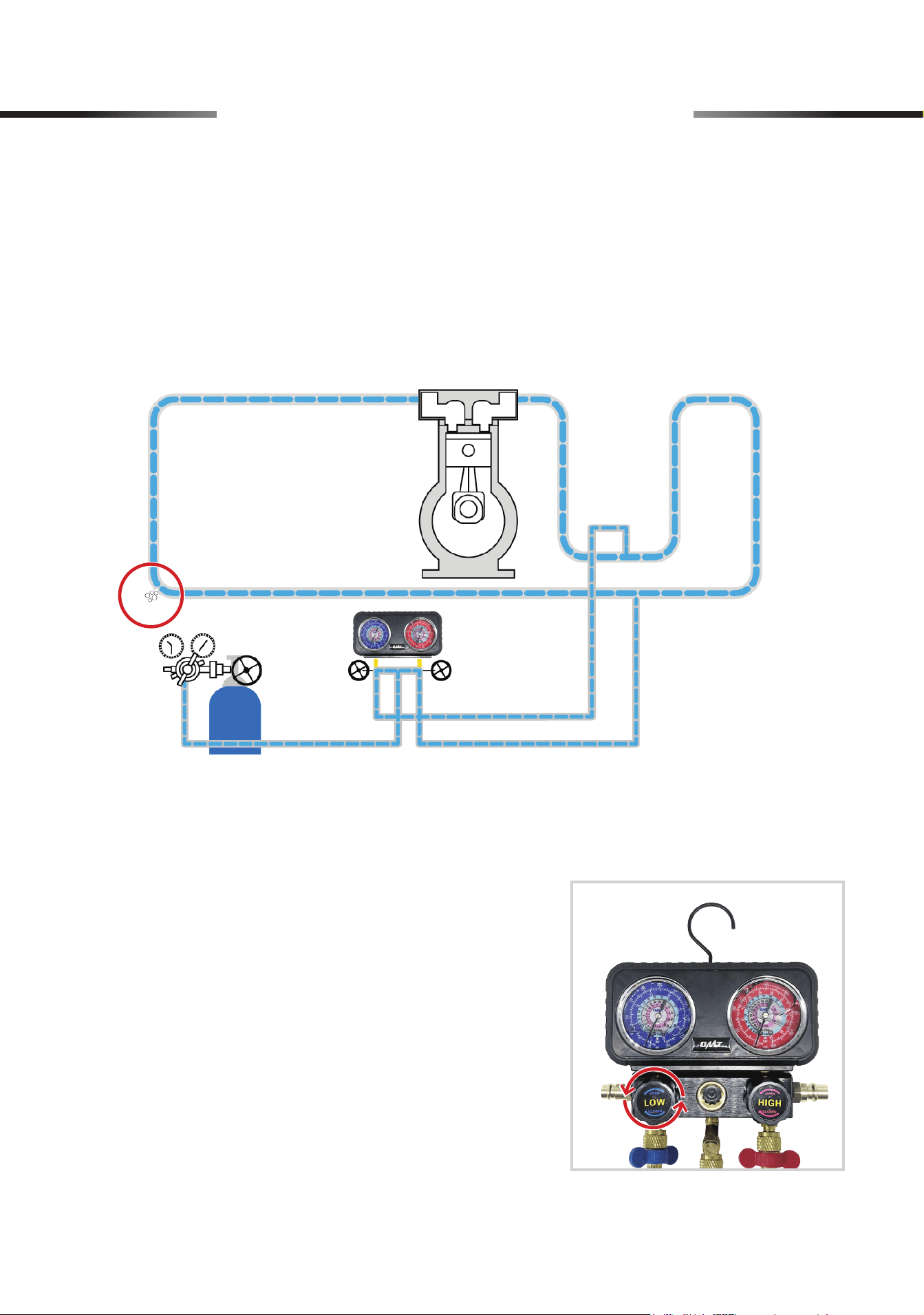
7.2 Evacuation
•
Again, check that your A/C system has been
COMPLETELY
turned o.
•
DO NOT
vent refrigerant to the atmosphere. Use appropriate recovery equipment.
1. Connect a micron gauge (not included) to the
E/C port and the yellow hose.
8. Once the pressure readings indicate 0 psi,
close the LP valve by turning its knob (LOW)
completely clockwise.
Note: Use the hose end WITHOUT a
copper core inside.
7 AC System Operation
14
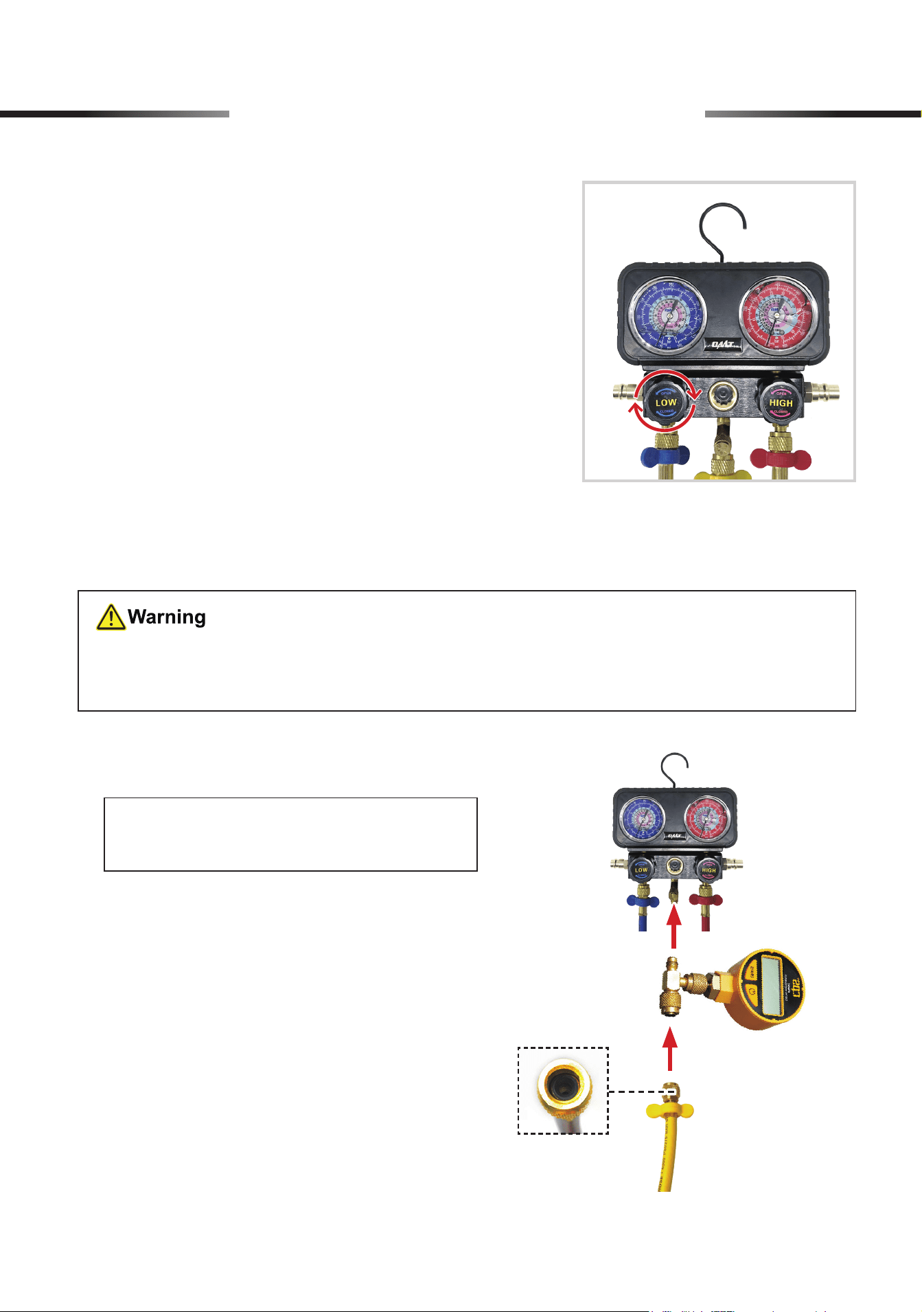
3. Make sure all connections are tightly joined and
turn the micron gauge on.
4. Open the LP valve by turning its knob (LOW)
completely counterclockwise. Turn on the
pump, and the evacuation begins.
5. When the micron gauge reads less than
500
microns, your A/C system is fully cleared.
Close the LP valve by turning its knob (LOW)
COMPLETELY
clockwise and turn off the
pump.
6. Disconnect the micron gauge from the gauge set and the yellow hose. Disconnect the yellow
hose from the pump.
2. Connect the other end of the yellow hose to a
vacuum pump (not included) using its copper
core end.
Note:
• If the port of your pump does not
fit the hose’s 1/4″ threads, use the
provided 1/4″ male to 1/2″ female
adapter (O) or other suitable adapter
to complete the connection.
• Recommended for use with OMT
vacuum pump.
7 AC System Operation
15
7.3 Charging
•
ALWAYS
keep your refrigerant cans away from heat sources and direct sunlight.
• Be sure
NOT
to open your refrigerant cans by accident in
ANY
way.
• Ensure that
BOTH
valves on the gauge
ARE
completely closed
BEFORE
starting work.
•
NEVER
leave your refrigerant cans or the gauge unattended when charging A/C systems.
•
ALWAYS
wear proper PPE when disconnecting the couplers and hoses after charging is
complete, as they may contain some refrigerant under pressure.
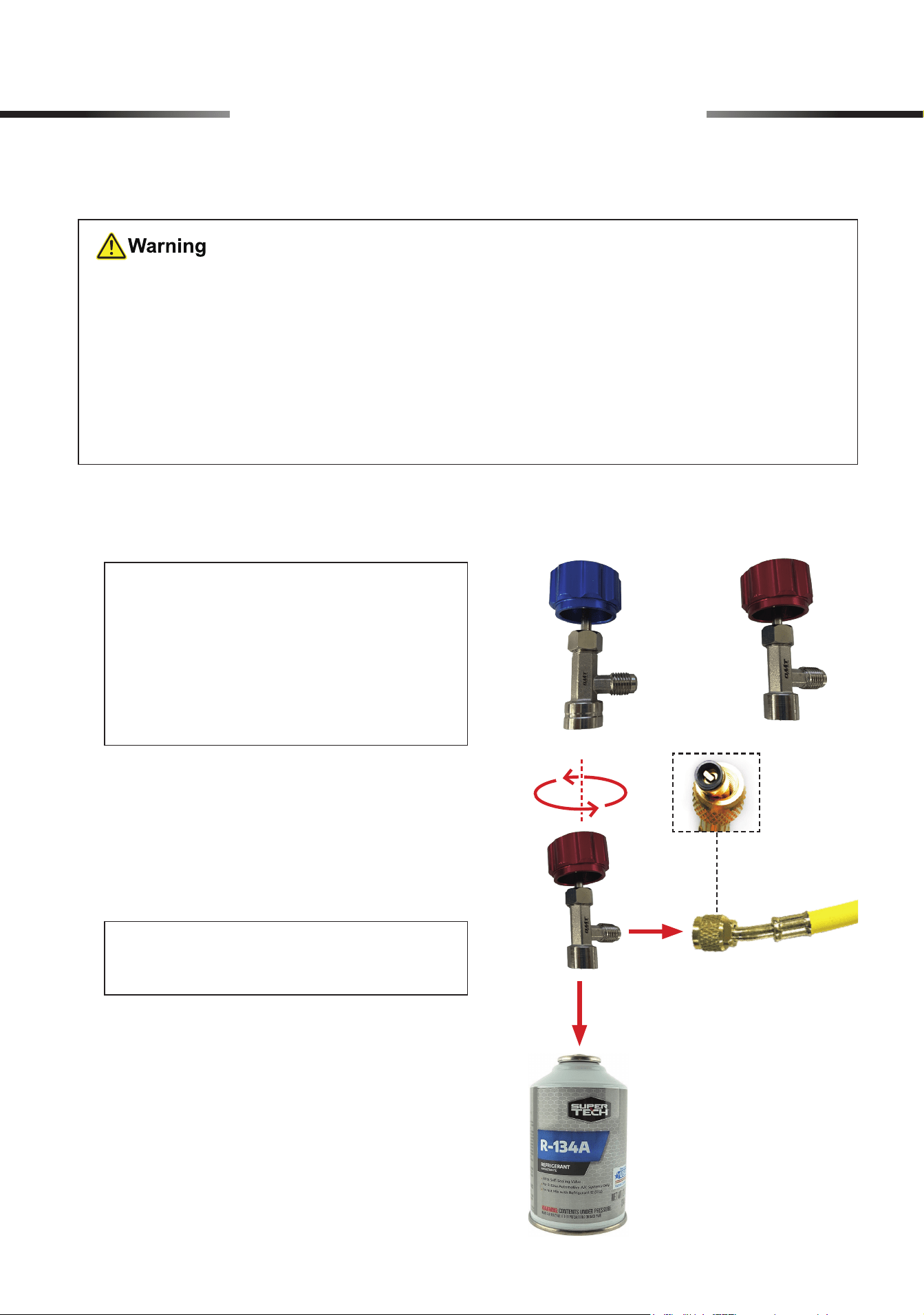
1. Choose a provided self-sealing can tap (J or
K) for your refrigerant can as you need.
2. Check that the tap has been closed by turning
its knob COMPLETELY counterclockwise.
Connect the outlet of the tap to the yellow
hose and its inlet to your refrigerant can.
For R1234yf
Refrigerant
(Example: R134a Refrigerant)
For R134a
Refrigerant
Note: Use the hose end WITH a copper
core inside.
Note:
• Use the red tap (J) for R134a refrigerant
cans. Use the blue tap (K) for R1234yf
refrigerant cans.
• Some big refrigerant cans have taps
to regulate the ow.
7 AC System Operation
16
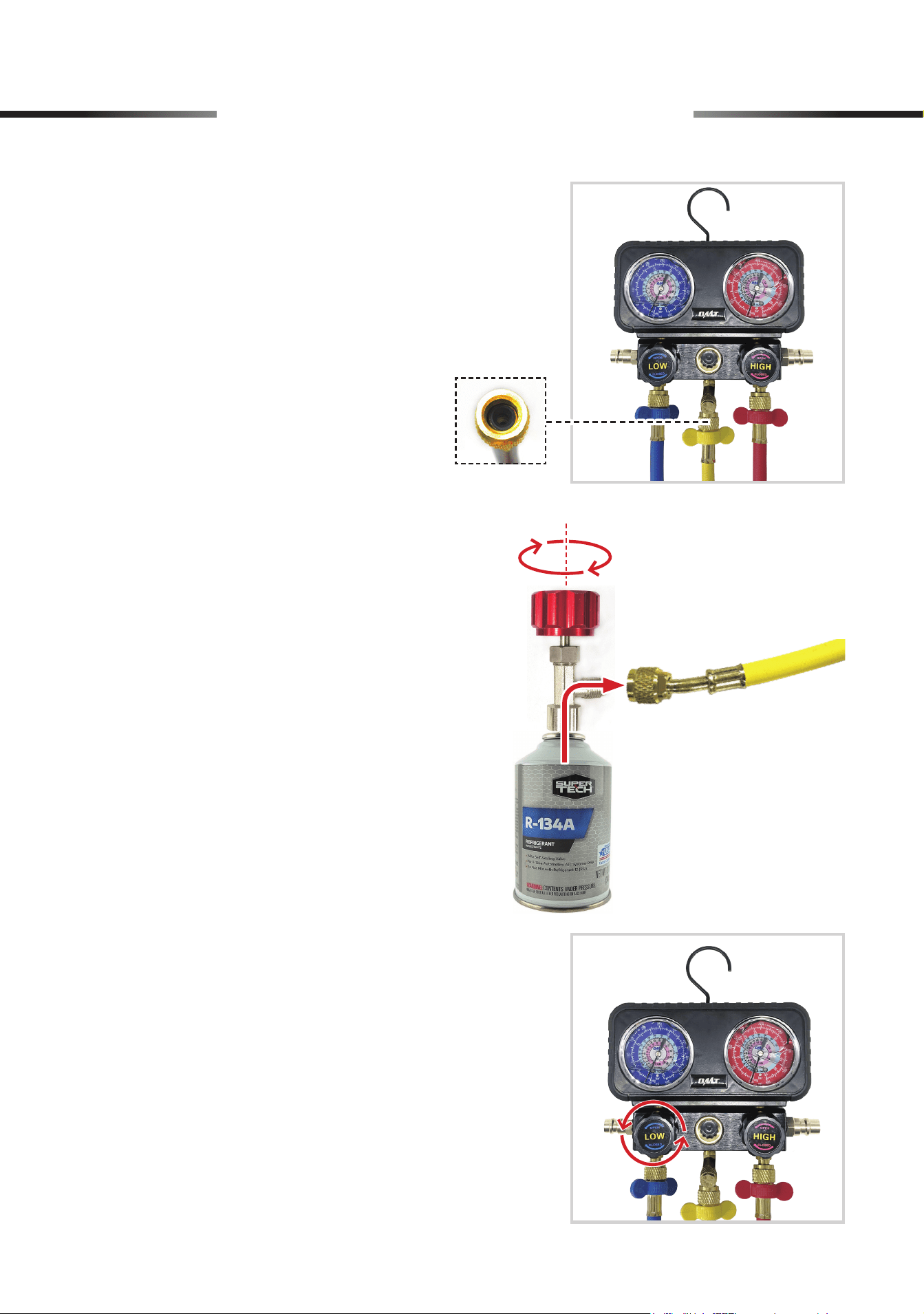
3. Connect the yellow hose to the E/C port of the
gauge set using the hose end WITHOUT a
copper core inside.
4. Turn the knob clockwise to allow the refrigerant
to ow through the hose.
5. Open the LP valve by turning its knob (LOW)
completely counterclockwise and charging
begins.
(Example: R134a Refrigerant)
7 AC System Operation
17
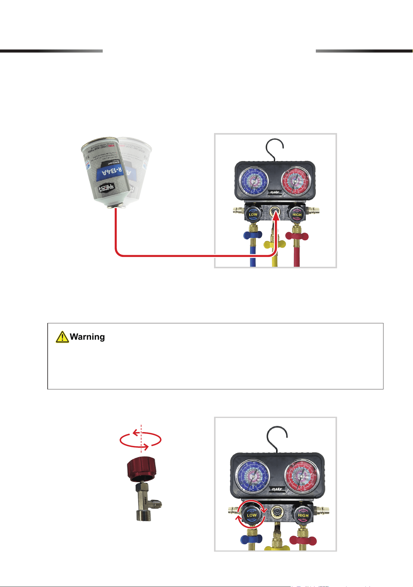
6. To check if the small refrigerant can is empty, invert the can and GENTLY shake it. If refrigerant
is visible from the glass window, there is still some refrigerant left in the can.
7. To change the small empty refrigerant can, you MUST close the LP valve by turning its
knob COMPLETELY clockwise and the tap’s knob COMPLETELY counterclockwise before
reconnecting a new refrigerant can.
(Example: R134a Refrigerant)
(Example: R134a Refrigerant)
• NEVER discard discarded refrigerant cans at will or put them in ordinary trash cans.
• Discarded refrigerant cans MUST be disposed of in accordance with local waste disposal
regulations.
7 AC System Operation
18
8. Consult your A/C system’s specications to nd its recommended pressure, usually between
25–80 psi (1.7–5.5 bars).
9. Once the system reaches the recommended pressure, stop charging the system by turning the
tap knob COMPLETELY counterclockwise and turning the LP valve knob (LOW) COMPLETELY
clockwise.
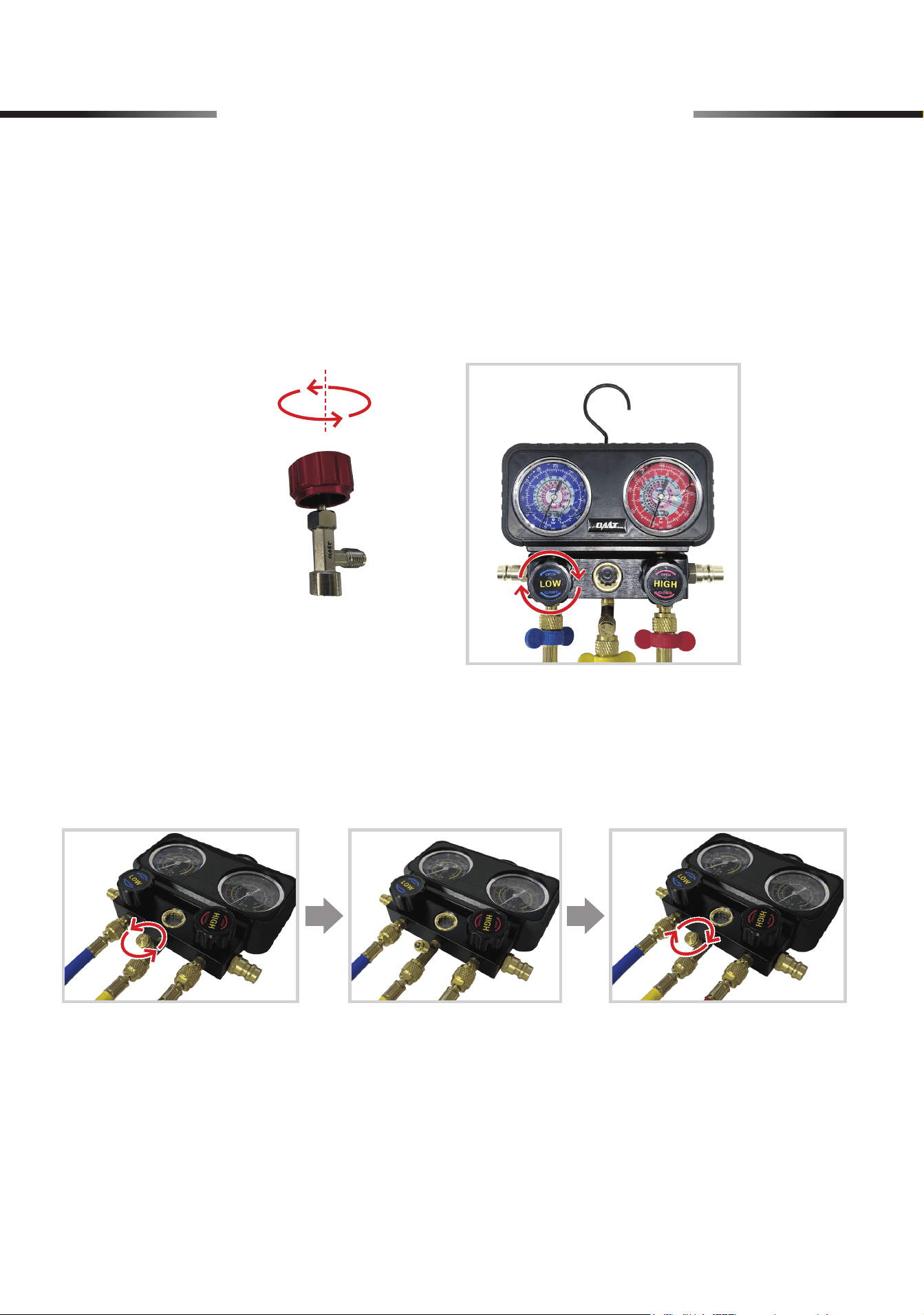
12. Disconnect the hoses from the quick couplers, the tap, and the gauge set.
13. Keep the tap securing on the partially used refrigerant can, or disconnect it from the empty can
or the self-sealing can.
10. Disconnect the two quick couplers from your A/C system and take down the gauge set.
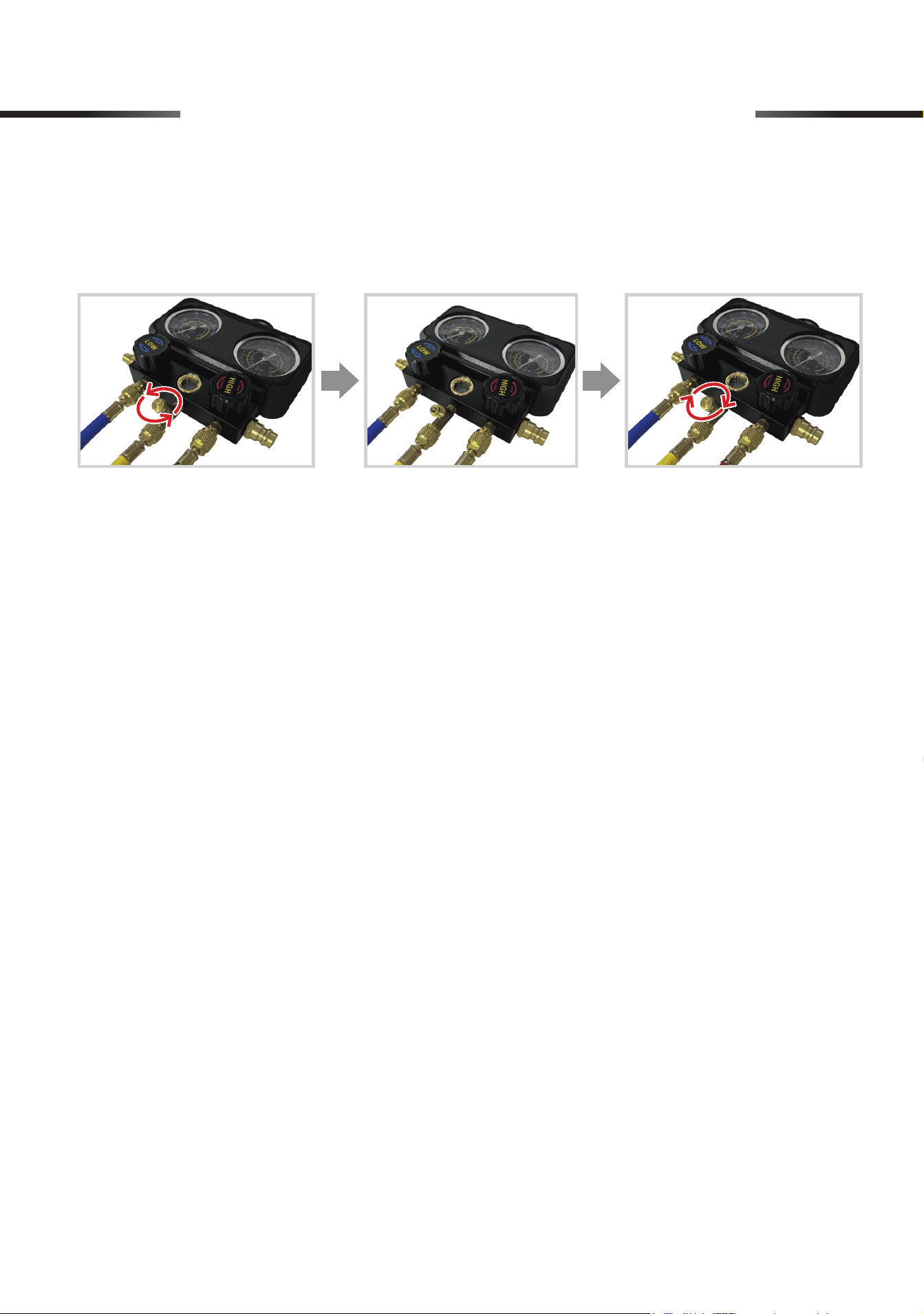
11. Open the unloading valve by unscrewing its cap to clear any air or vapor remaining inside the
gauge set. Conrm that the pressure readings indicate 0 psi, and then tighten the cap into
place.
(Example: R134a Refrigerant)
7 AC System Operation
19
8 Initial Setup of HVAC System
• Make sure your surroundings
ARE
safe for using this product.
Avoid operating in crowded, dark, or cluttered areas. Keep away from explosives or
ignition sources.
• Be sure that
ALL
connections
ARE
tightly secured.
• Make sure the HVAC system is turned o
BEFORE
starting work.
Note:
Wrapping the threads with sealing tape (not included) before making the connection,
helps prevent leaks.
1. Connect the hoses to the gauge.
For detailed steps, please see
6.1 Connecting the Hoses to the Gauge
on Page
7
.
2. Connect the blue and red hoses to the safety valves (I), and tighten the connections by
hand using the hoses’ locking nuts.
3. Screw and tighten the safety valve to the
HVAC system.
20
9 Operation of HVAC System
You can evacuate your HAVC system, and then charge it with refrigerant.
9.1 Performing Leakage Test
For detailed steps, see
7.1 Performing Leakage Test
on Page
11
.
9.2 Evacuation
• Again, make sure your HAVC system is
COMPLETELY
turned o.
•
DO NOT
vent refrigerant to the atmosphere. Use appropriate recovery equipment.
For detailed steps, see
7.2 Evacuation
on Page
13
.
9.3 Charging
•
ALWAYS
keep your refrigerant tank away from heat sources and direct sunlight.
• Make sure
NOT
to accidentally open your refrigerant tank.
• Make sure that
BOTH
valves on the gauge
ARE
completely closed
BEFORE
starting
work.
•
NEVER
leave your refrigerant tank or the gauge unattended when charging the HAVC
system.
•
ALWAYS
wear proper PPE when disconnecting the couplers and hoses after charging
is complete.
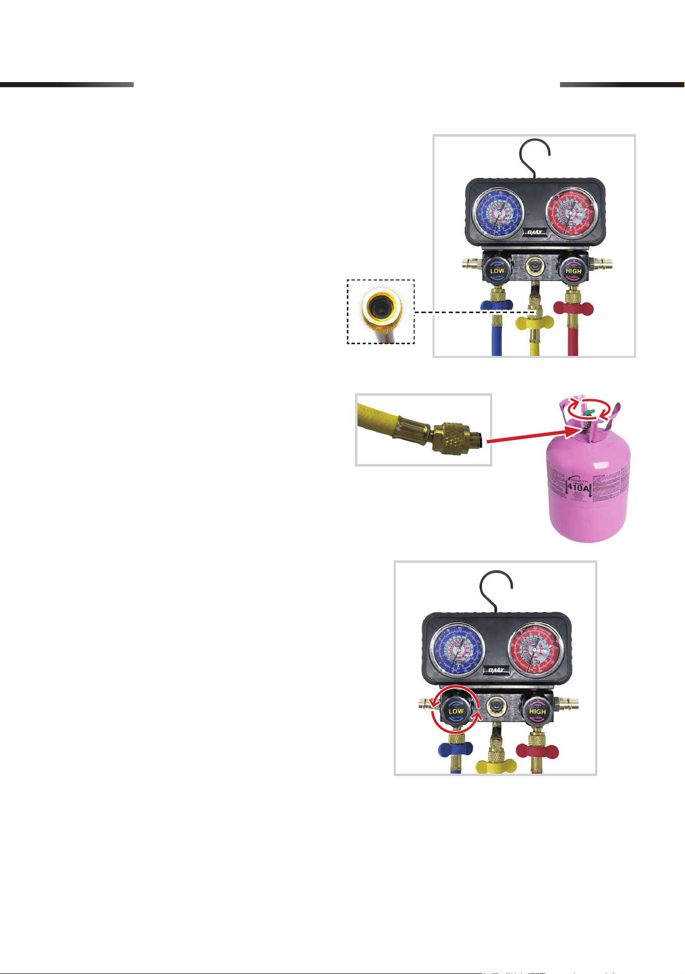
1. Screw and tighten the yellow hose to the
refrigerant tank.
21
9 Operation of HVAC System
2. Connect the yellow hose to the E/C port
of the gauge set using the hose end
WITHOUT
a copper core inside.
3. Turn the valve clockwise to allow the
refrigerant to ow through the hose.
4. Open the LP valve by turning its knob
(LOW) completely counterclockwise and
charging begins.
22
9 Operation of HVAC System
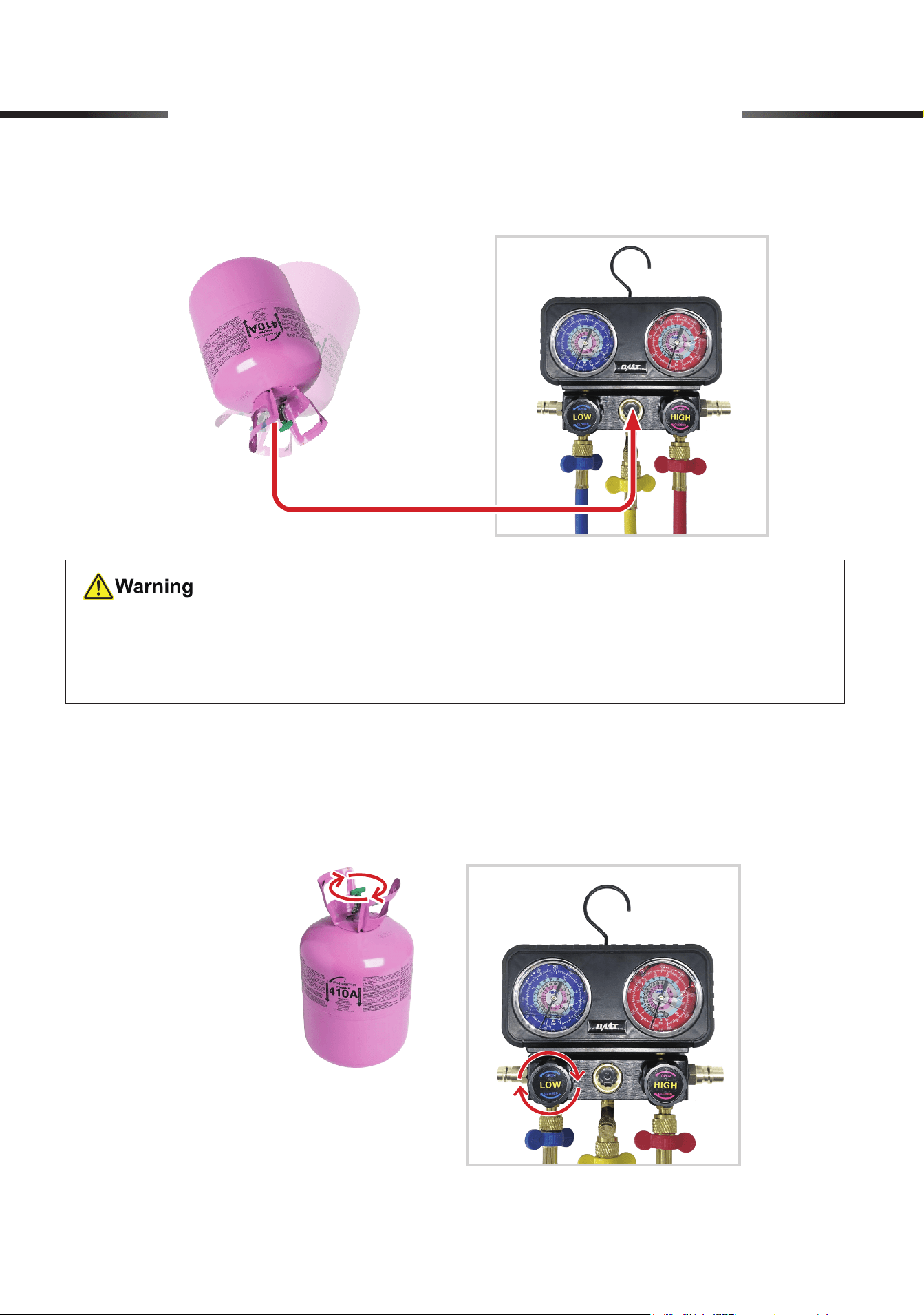
5. To check if the refrigerant tank is empty, invert the tank and
GENTLY
shake it. If refrigerant
is visible from the glass window, some are still left in the can.
6. Consult your system's specifications to find its recommended pressure, usually between
110 to 130 psi (0.8 to 0.9 MPa) for R410a.
7. Once the system reaches the recommended pressure, stop charging by turning the valve
COMPLETELY
counterclockwise and the LP valve knob (LOW)
COMPLETELY
clockwise.
•
NEVER
dispose of refrigerant tanks at will or put them in ordinary trash.
• Discarded refrigerant tanks
MUST
be disposed of according to local waste disposal
regulations.
23
8. Disconnect the two safety valves from your HAVC system and take down the gauge set.
9. Open the unloading valve by unscrewing its cap to clear any air or vapor remaining inside
the gauge set. Conrm that the pressure readings indicate 0 psi, and then tighten the cap
into place.
9 Operation of HVAC System
10. Disconnect the hoses from the safety valves, the tap, and the gauge set.
11. Securely close the partially used refrigerant can.
24
10 Maintenance
• NEVER scrape the hose or drop the gauge set on hard or rough surfaces.
• Check the parts for misalignment, cracks, and any other conditions that may aect the operation
accuracy before use.
• If any gasket, O-ring, or copper core in the preinstalled refrigerant cap tap, quick coupler, or
any hose is damaged or worn, replace it with its spare part (P, Q, R or S) using the valve core
wrench (T) and/or dual-purpose screwdriver (H). If any other part of the gauge set is damaged
or worn, have it repaired or replaced before further use.
• Clean the exterior of the gauge set and hoses with a soft damp cloth using a mild detergent or
solvent. DO NOT use harsh abrasives or caustic chemicals.
• Store the gauge set in a clean dry place inaccessible to children and away from direct sunlight
after use.
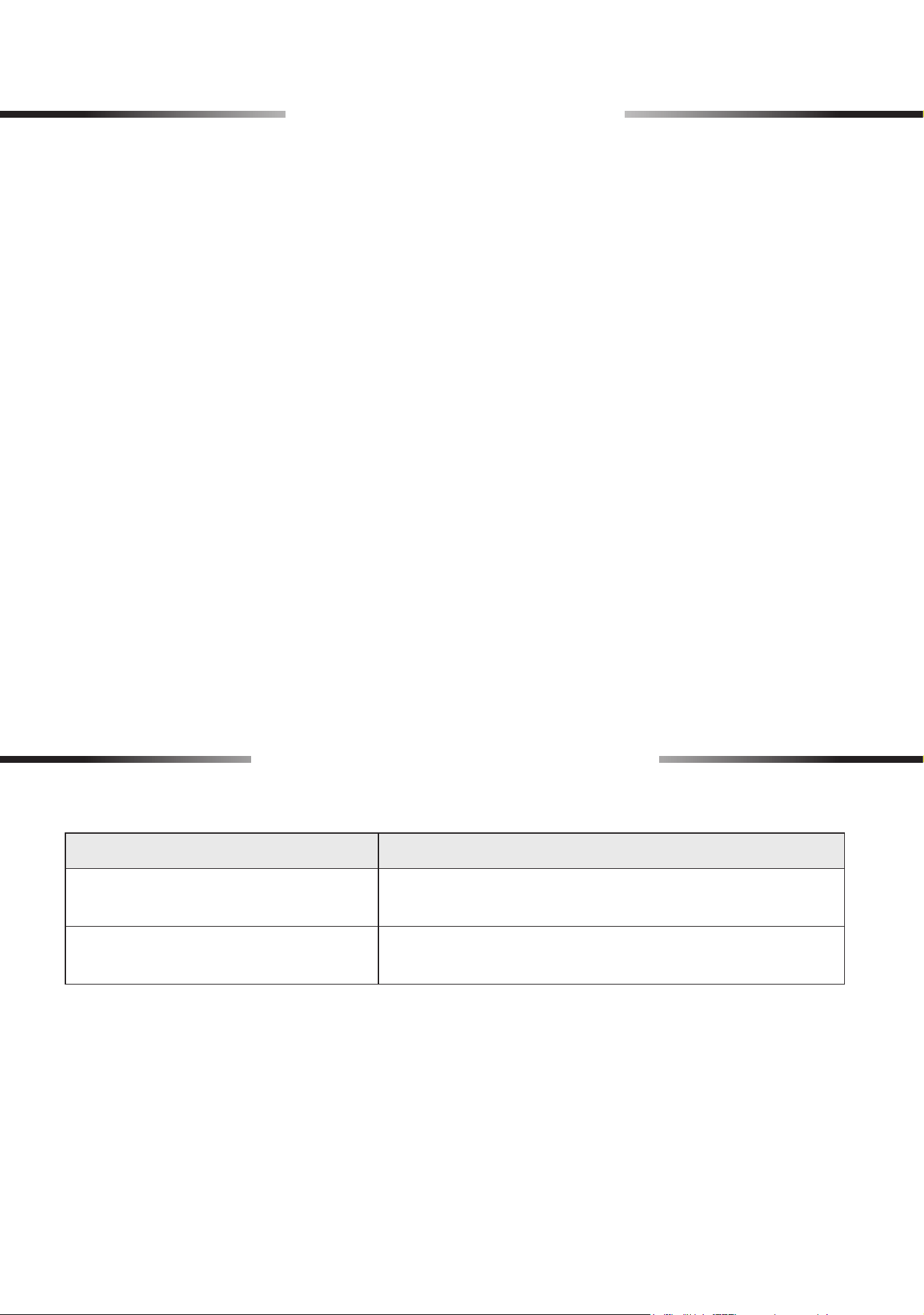
11 Troubleshooting
Problems Solutions
Pressure readings are unstable or
uctuating.
Check all connections and seals for leaks. Ensure
stable ambient temperature conditions.
The gauge set displays abnormally
high or low readings.
Check if ambient temperature is aecting the readings.
Inspect for any pressure leaks.
Rev. 26 Mar. 2025
Thank you for choosing our products! If you have any questions or
comments, contact us and we'll resolve your issues ASAP!
support@orionmotortech.com
Contact Us
Scan for the latest
user manual