
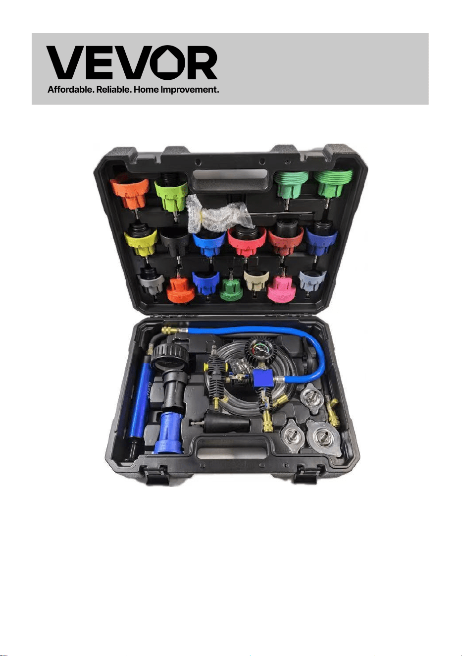
Coolant Pressure Tester/Coolant Vacuum
Refill
Model: YS-01205A,YS-01205B
VEVOR Support
Center
YS-01205A YS-01205B


Model: YS-01205A,YS-01205B
This is the original instruction, please read all manual instructions carefully
before operating. VEVOR reserves a clear interpretation of our user
manual. The appearance of the product shall be subject to the product you
received. Please forgive us that we won't inform you again if there are any
technology or software updates on our product.
Coolant Pressure Tester/
Coolant Vacuum Refill
SPECIFICATION
Model
YS-01205A
YS-01205B
Pressure Range
0~2.5bar/0~35psi
Instrument vacuum
range
-76~0cmHg(-30~0inHg)
Material of
Coolant Vacuum Refill
Aluminum &plastic
with copper
Plastic with copper
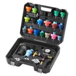
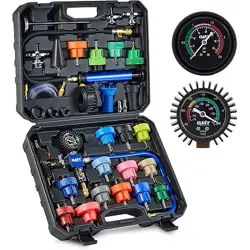
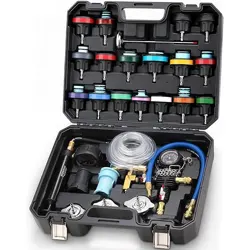
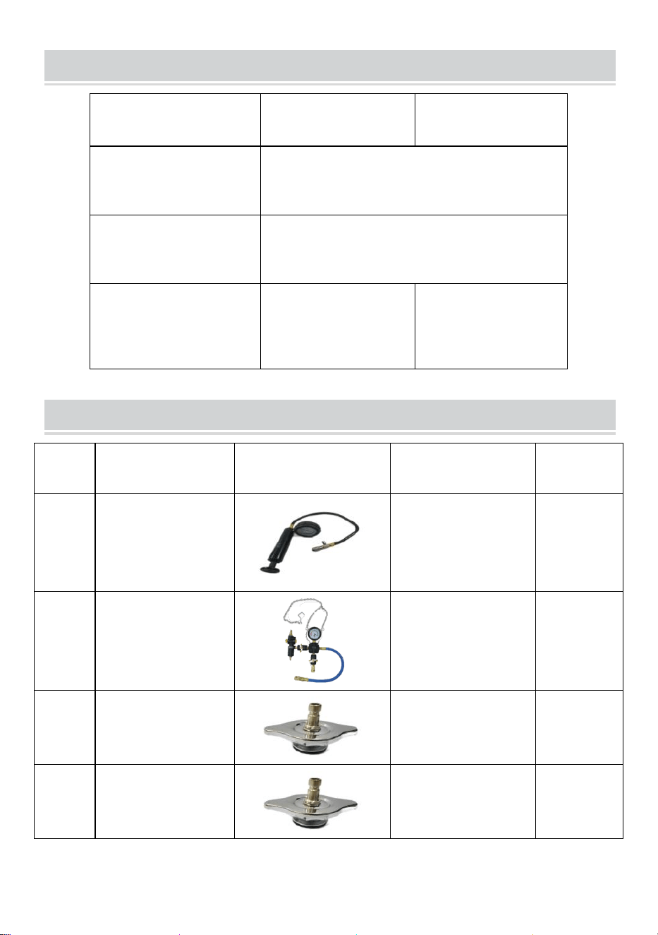
PACKAGE LIST
NO.
Part
Picture
Specification
QTY
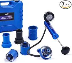
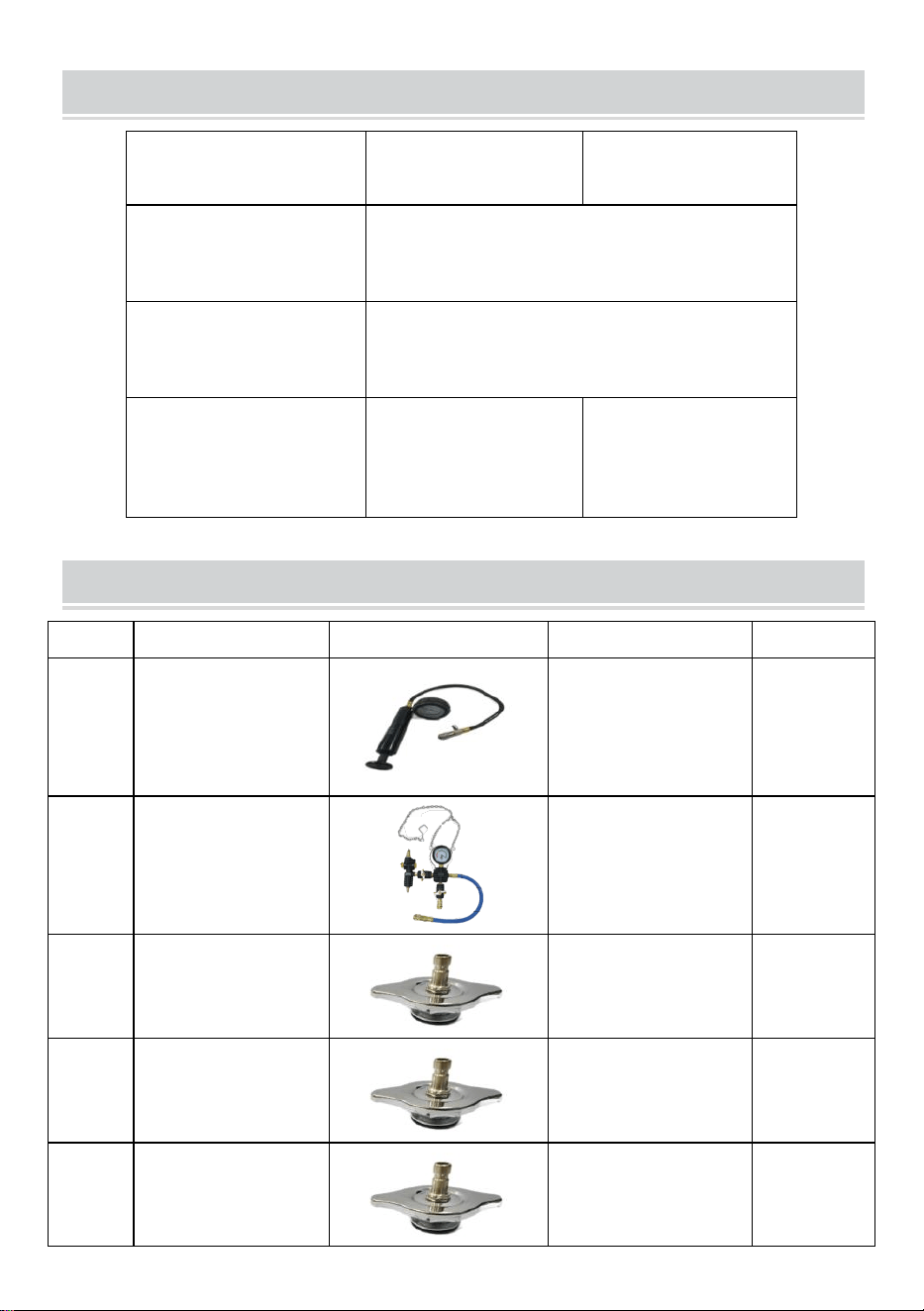
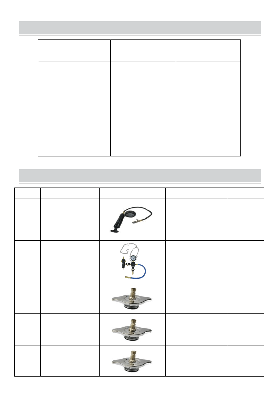
1
Coolant Pressure
Pump
/
1
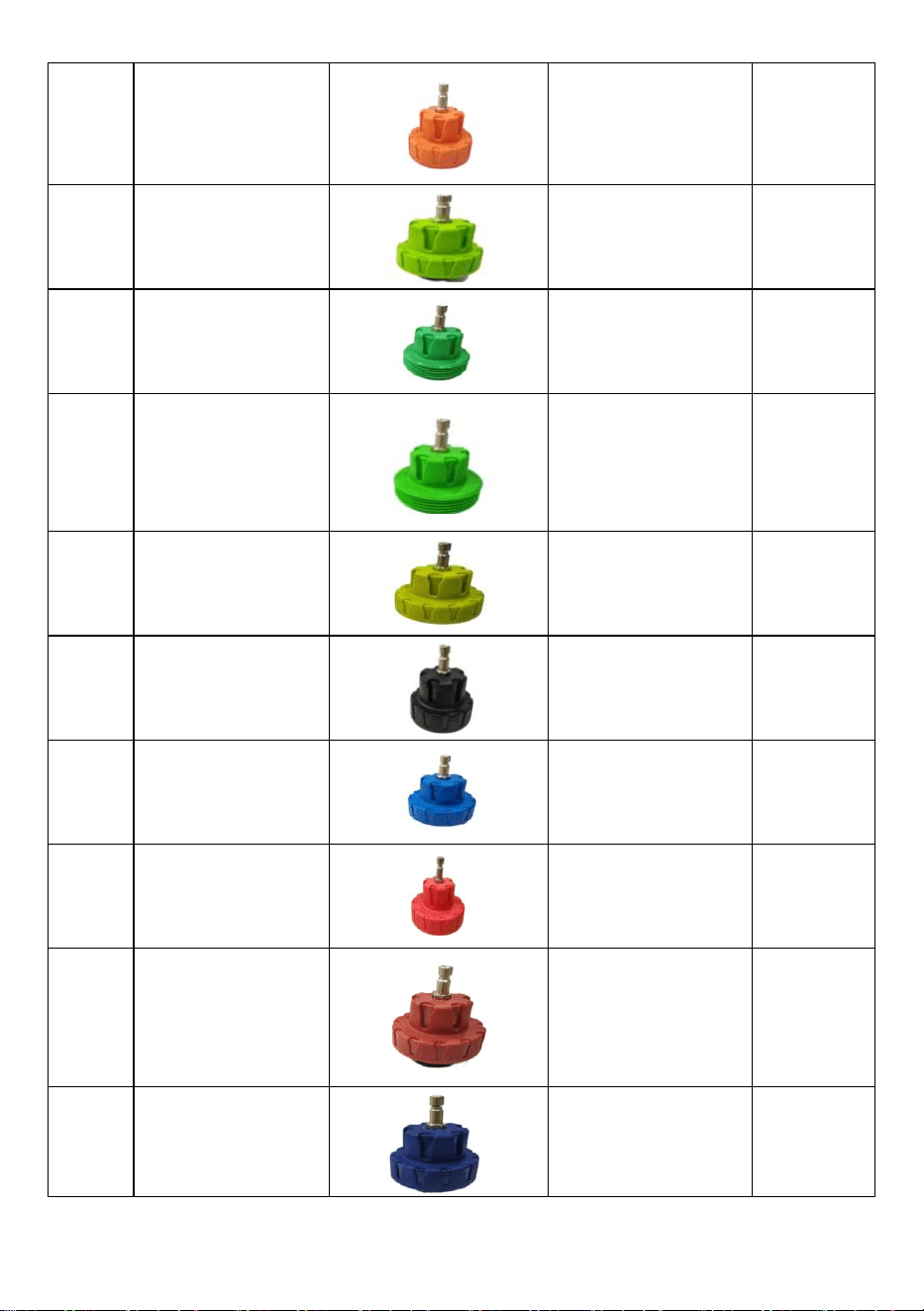
2
Coolant Vacuum
Refill
Included US
Standard air
nozzle adapter
1
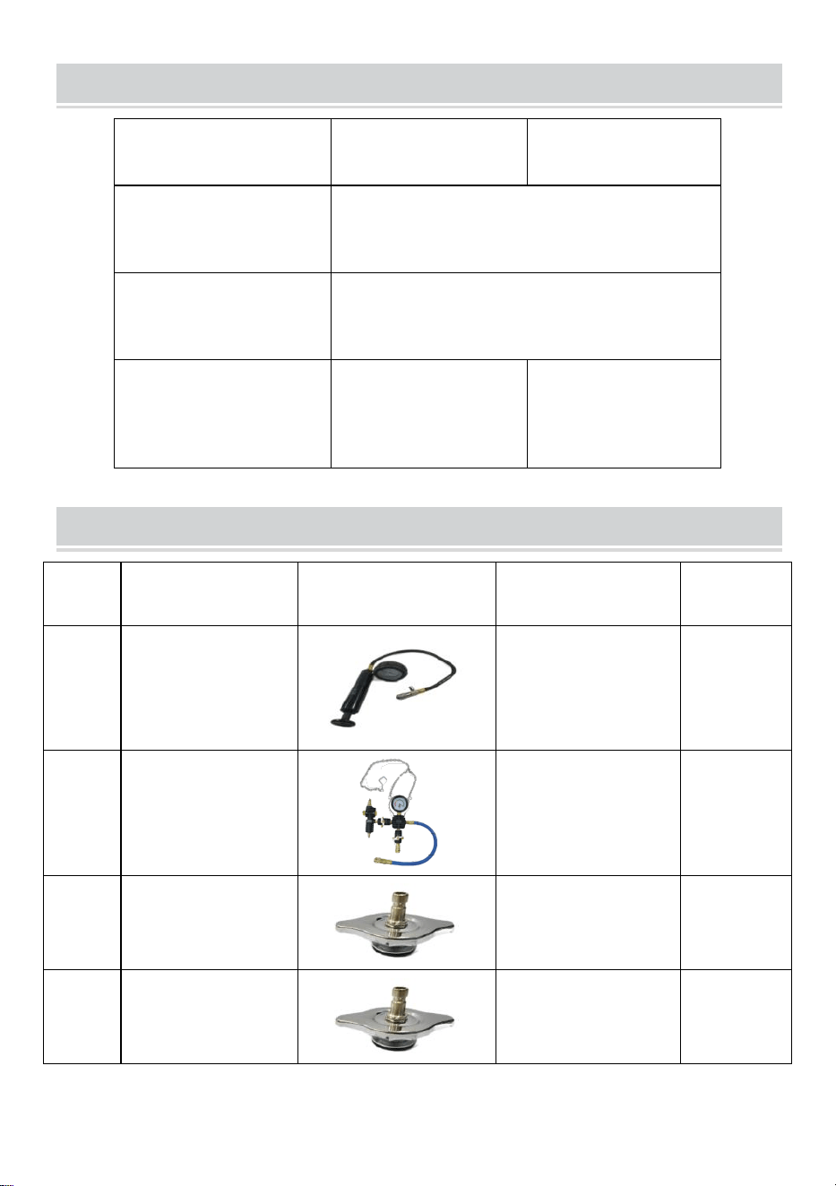
3
3# Testcap
/
1
4
4# Testcap
/
1
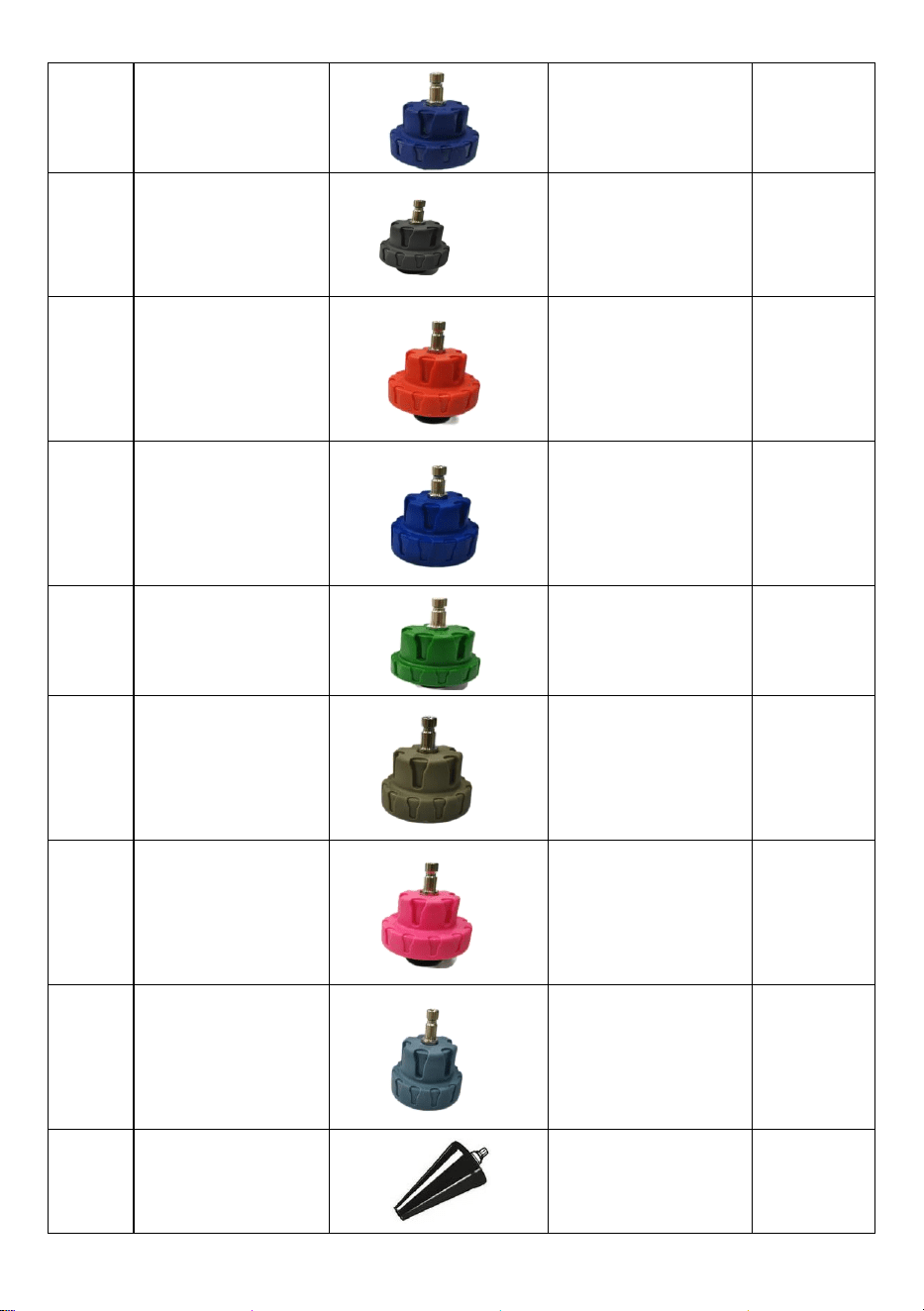
5
5# Testcap
/
1
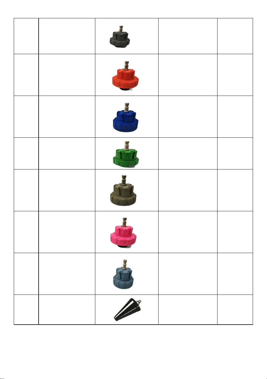
6
6# Testcap
Diameter:
M50*3.5
English10buds
1
7
7# Testcap
Diameter:
M45*3.5
English9buds
1
8
8# Testcap
Diameter:
M57*3English9
buds
1
9
9# Testcap
Diameter:
M62*3English
9buds
1
10
10# Testcap
Diameter:
M49*4.5
English6buds
1
11
11# Testcap
Diameter:
M46*3.5
English9buds
1
12
12# Testcap
Diameter:
M51*3English
8buds
1
13
13# Testcap
Diameter:
M61*4English
6buds
1
14
14# Testcap
Diameter:M53*3
English 9 buds
1
15
15# Test cap
Diameter:
M48*2.5 English
9 buds
1
16
16# Test cap
Diameter:M45*3
English 8 buds
1
17
17# Test cap
Diameter:M50*3
English 8 buds
1
18
18# Test cap
Diameter:M47*3
English 9 buds
1
19
19# Test cap
Diameter:M34*3
1
20
20# Test cap
Diameter:M44*3
English 8 buds
1
21
21# Test cap
Diameter:M52*3
English 9 buds
1
22
22# Test cap
Diameter:M44*3
English 8 buds
1
23
Cone universal
adapter
Interface: M10
1
24
Thermometer
Range:0-200°
C/32-400°F
1
25
Cap wrench
/
1
26
Sealing ring
/
15
27
Air nozzle
adapter
European
standard
1
28
Coolant hose
1.5m
×Φ
12mm
、
0.4m
×Φ
9mm
2
29
PTFE strip
/
/
1
30
Manual
/
1
SECURITY&WARNINGS

1. Follow workshop Health & Safety rules, regulations and conditions
when using this equipment.
2. WARNING! Disconnect from air supply before changing accessories or
servicing.
3. Maintain the equipment in good condition and replace any damaged or
worn parts.
4. Use genuine parts only. Unauthorised parts may be dangerous and will
invalidate the warranty.
5. WARNING! Check that correct air pressure is maintained and DOES
NOT exceed 100psi.
Study, understand and follow all instructions provided
with this product. Read these
instructions carefully
before installing, operating, servicing or repairing this
tool.
Keep these instructions in a safe accessible place.
INTENDED USE OF THE TOOL
This kit is designed to test for leakage in vehicle cooling
systems, including radiator
caps, and for quick change of coolant only. Use as intended only.
Always read the instructions carefully before using the tool.
This tool kit is for cooling system maintenance only.
Ensure the working area has adequate lighting.
Keep children and unauthorized persons away from the working
area ·
Keep working area clean and tidy, dry and free from unrelated materials
DO NOT allow untrained persons to use this tool kit.
Always wear eye protection that meets OSHA and ANSI Z87.1
Wear eye
protection
Refer to
instructions
Wear protective
gloves
Wear safety
footwear
Wear protective
clothing

standards.
Always wear gloves when working with the tool.
Always wear ear protection.
Disposal: Customers should follow local regulations to handle used or
waste parts.
Do not remove the radiator cap or coolant bottle cap when the engine is
hot or at operating temperature. Let the engine cool first. Failure to heed
this warning may cause damage and/or personal injury.
BEFORE USE
DO NOT DISCARD-GIVE TO THE USER
Coolant can spray out.
Before dismantling the pump or the adapter, release the pressure.
Check the cooling fluid after the pressure test or repair to the correct
level and frost protection.
Take care when working on running engines, Loose or baggy clothing
can be caught in rotating engine parts.
INSTRUCTIONS
Coolant Pressure Tester
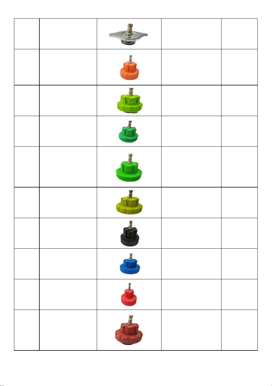
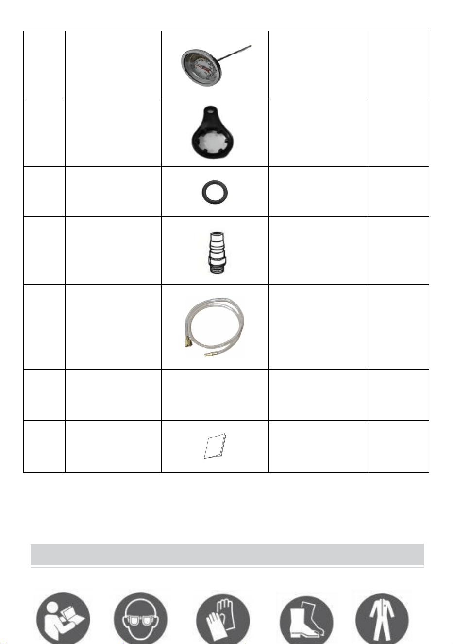
1. Cooling System Leakage Test
1.1 Removing the original radiator cap from the radiator or expansion tank.
1.2 Choose the appropriate adapter from the test set and connect it to the
radiator or expansion tank.
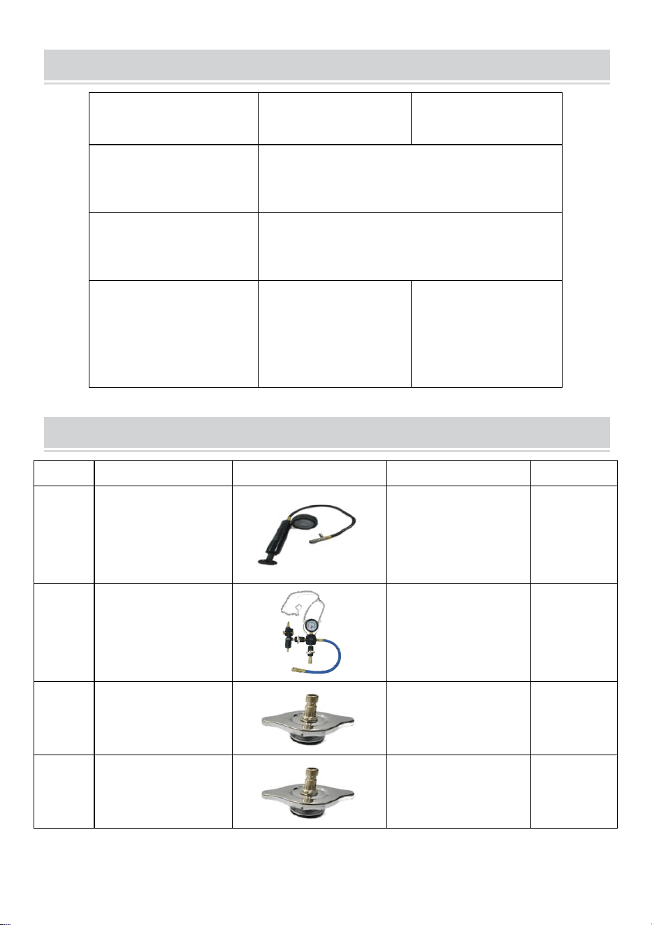
1.3 Now connect the hand pump(1) to the adapter.
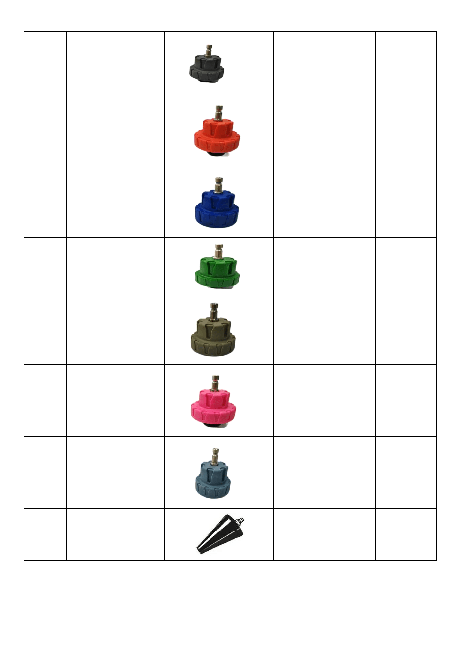
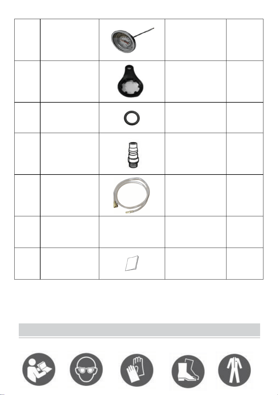
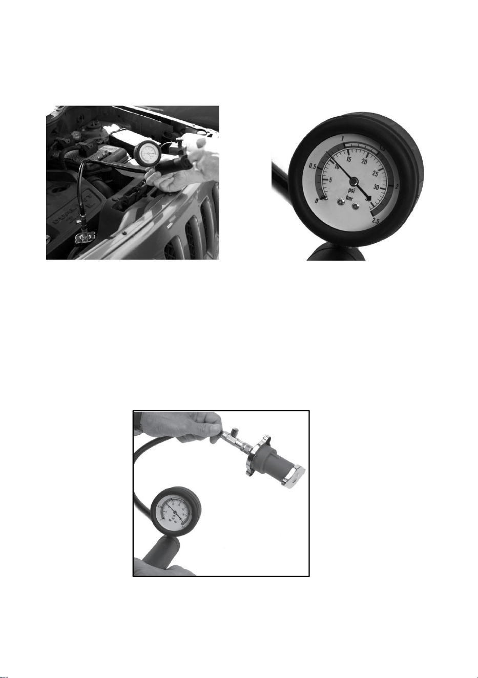
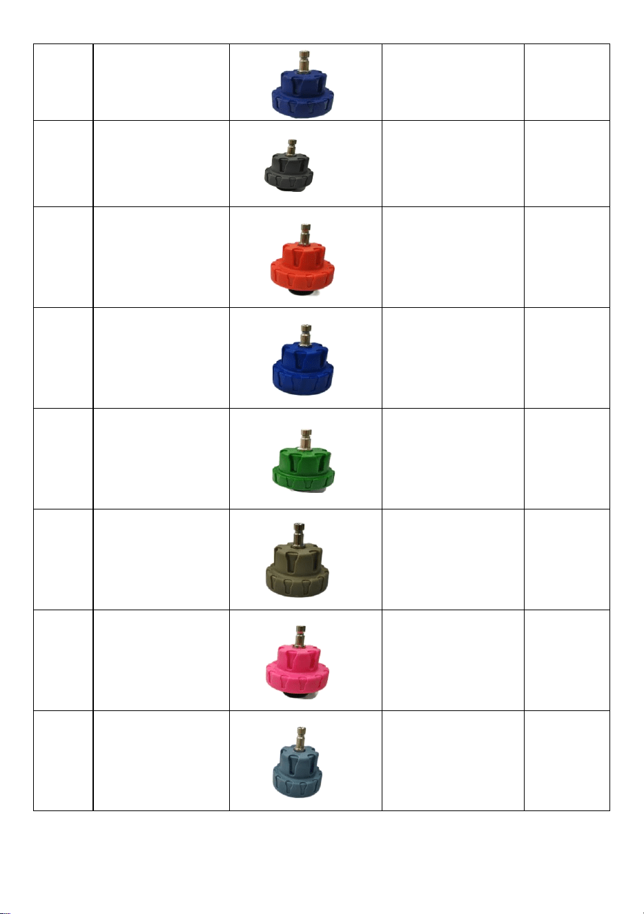
1.4 Press the test pump until pressure of 10 to 15psi is reached (see figure
1+2)
CAUTION: Avoid a pressure of 35psi or more!
Check the pressure gauge. If the displayed value decreases, the leakage
is in the cooling system.
The cooling system has a leak if there is a pressure drop or water loss.
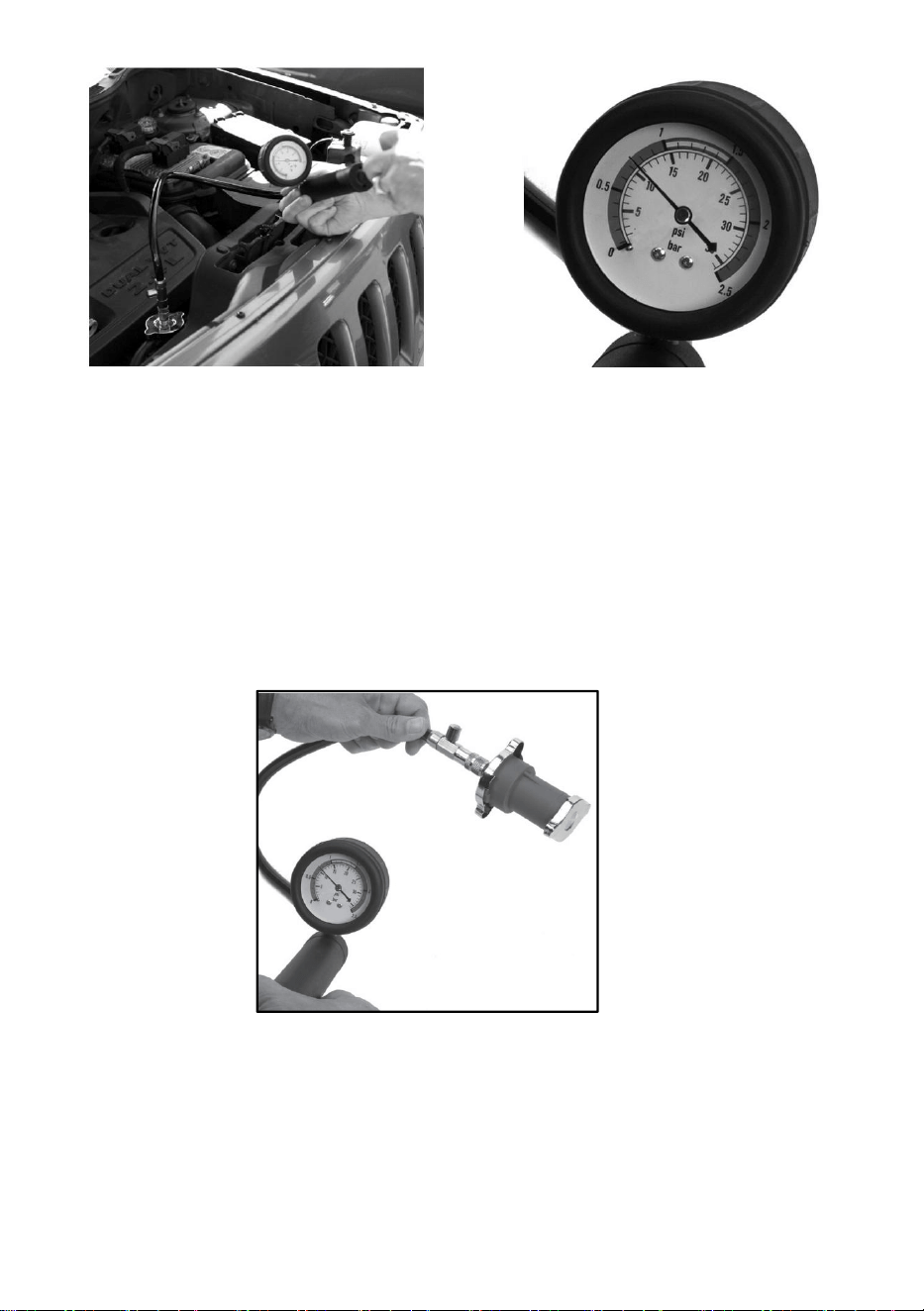
Fig.1 Fig.2
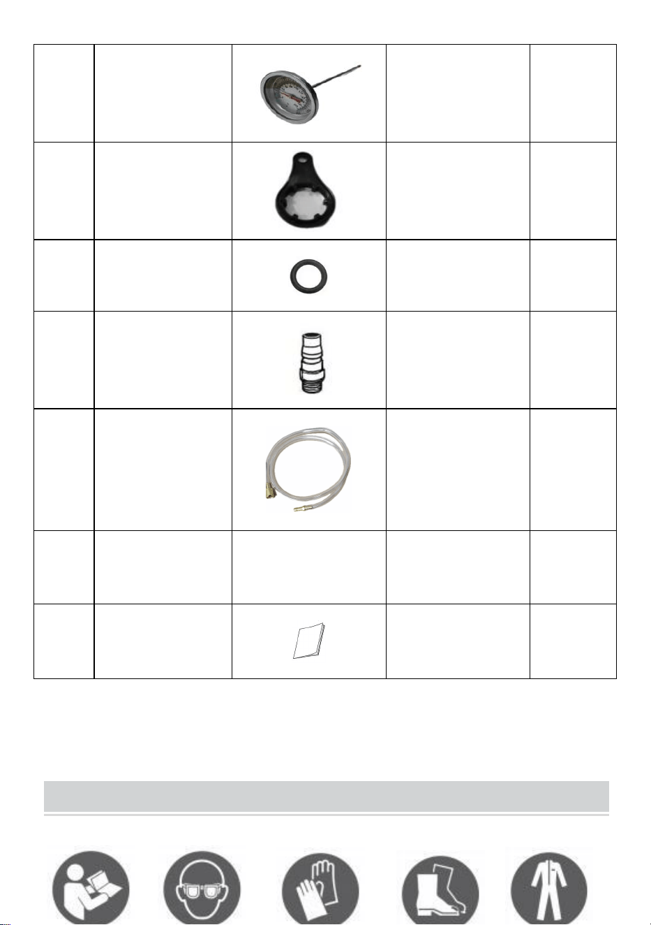
2. Radiator Cap Leakage Test
2.1 Remove the original radiator cap.
2.2 Choose the appropriate joint 2a or 2ba and connect it to the radiator
cap.
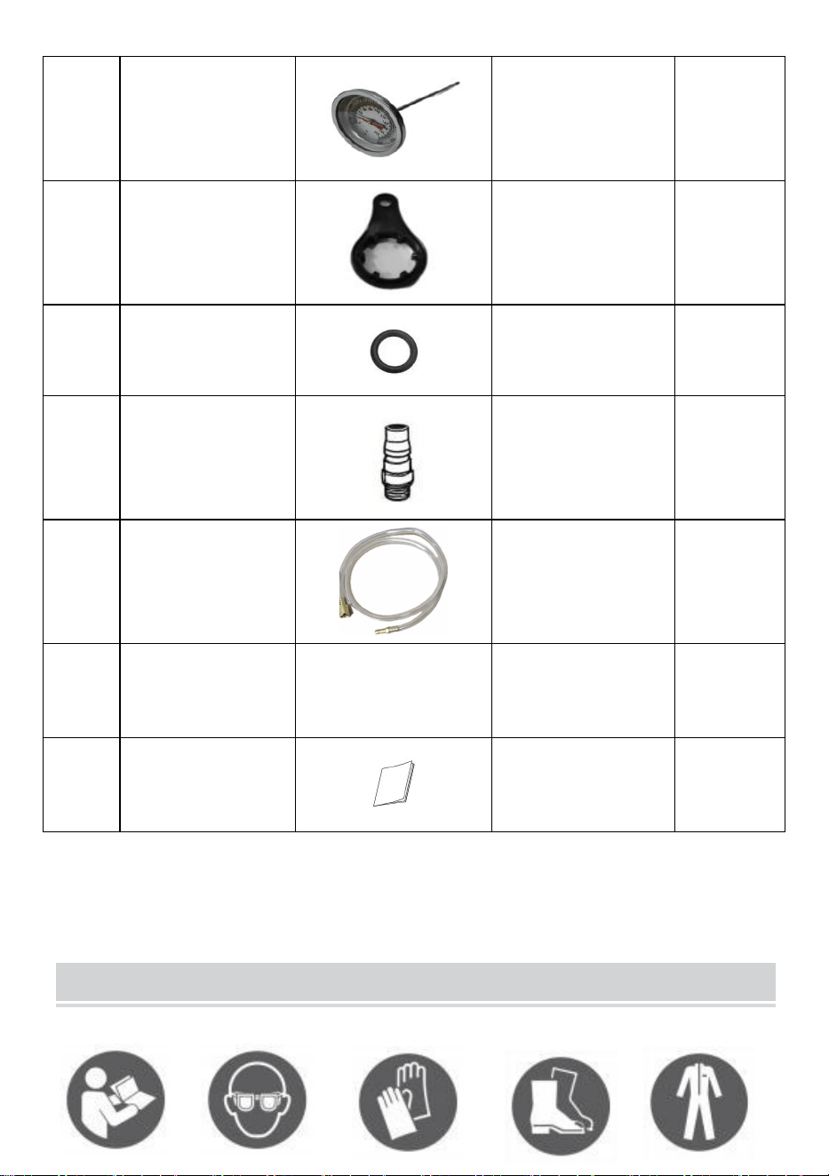
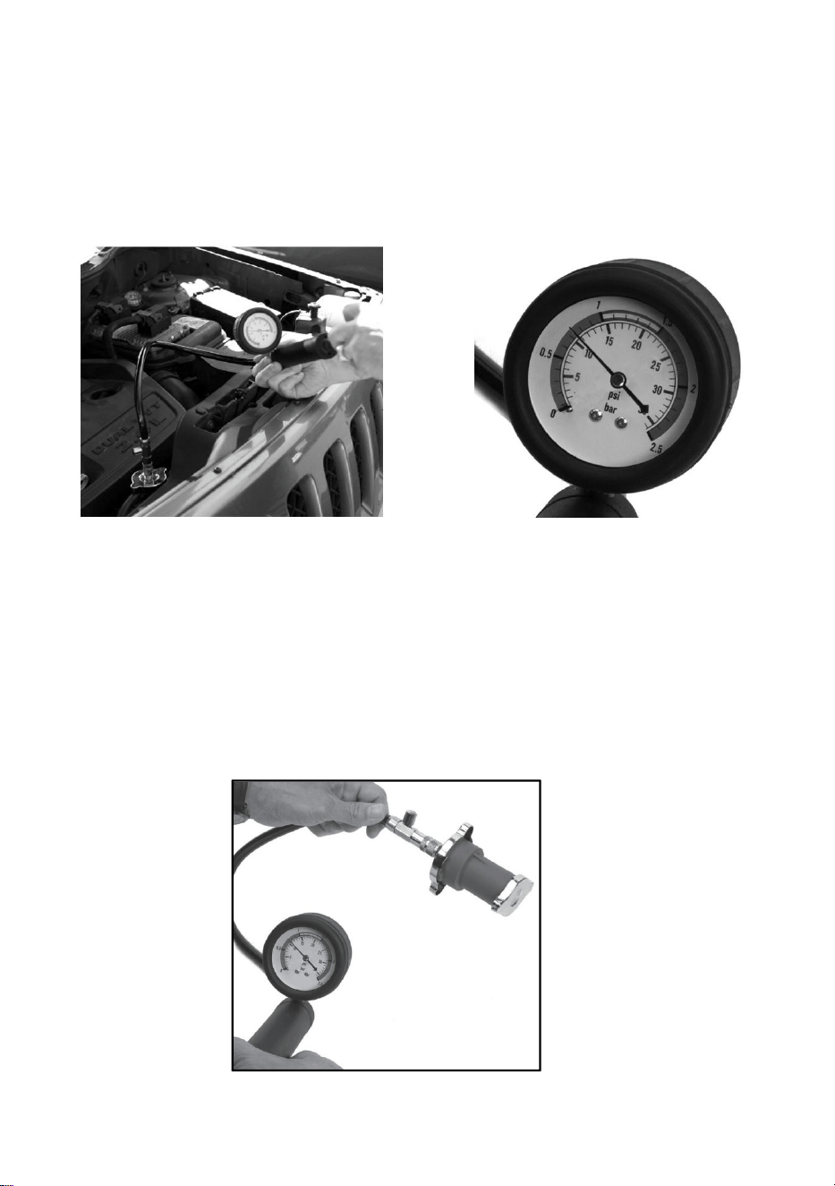
2.3 Press the test pump for few times and watch the pressure gauge. The
pressure falls if the cap is defective.(see fig.3)
2.4 Compare the measured pressure values with the standard pressure of
the radiator cap.
Fig.3
MAINTENANCE / STORAGE
Attach the test adapter to the quick coupler of the hand pressure pump,
then press the hand pressure pump a few times to push remnant water
out of the test adapter.
Drop pneumatic oil into the air hole of the hand pump end to lubricate
the piston of the hand pump.
Coolant Vacuum Refill
1. AIR SUPPLY
1.1 Ensure the valve is closed when connecting to the air supply.
1.2 You will require an air pressure of 90psi, and an air flow
according to specification.
2 PREPARATION
2.1 Set vehicle heater control to ‘On’ and/or ‘Hot’. Drain and flush
coolant system.
2.2 Inspect all coolant system components and repair/replace any
unserviceable items.
2.3 Prepare a suitable coolant mix (see vehicle handbook). Mix 10%
more than the system volume to ensure that the filler hose will always be
submerged.
2.4 Connect the item to the air system as described above.
3 FILL COOLING SYSTEM
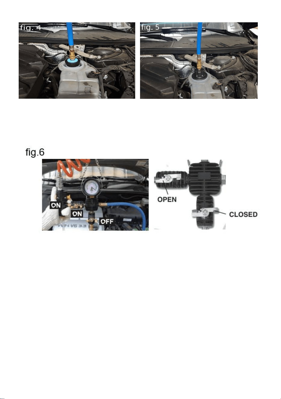
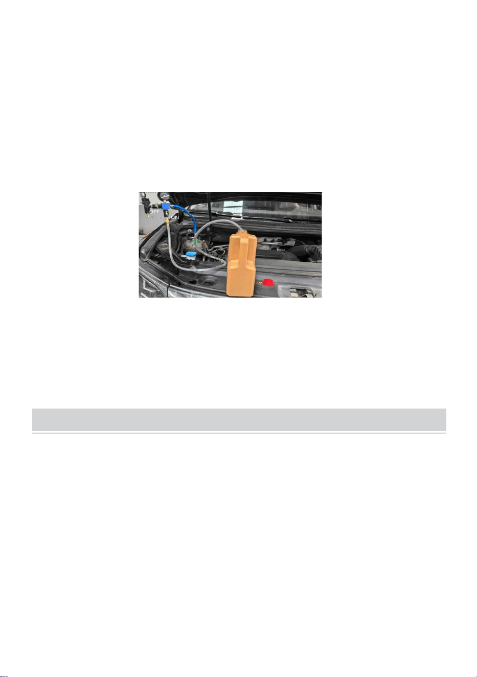
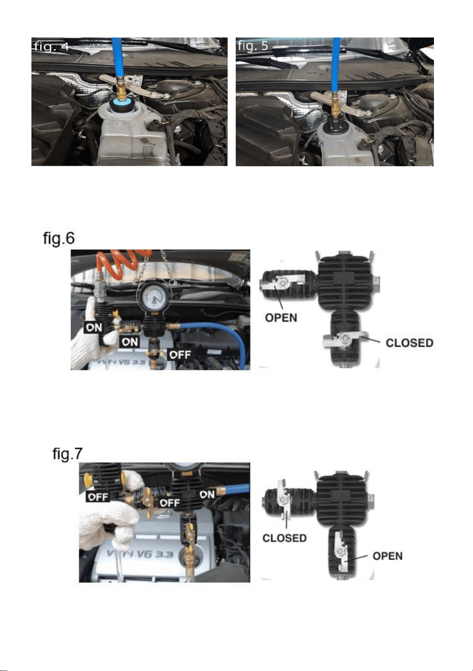
3.1 Open the hood and attach a vacuum pump with hooks on the hood.
3.2 Remove radiator or reservoir cap. Drain completely coolant at a
suitable place.The procedure can be found in the vehicle-specific service
literature.
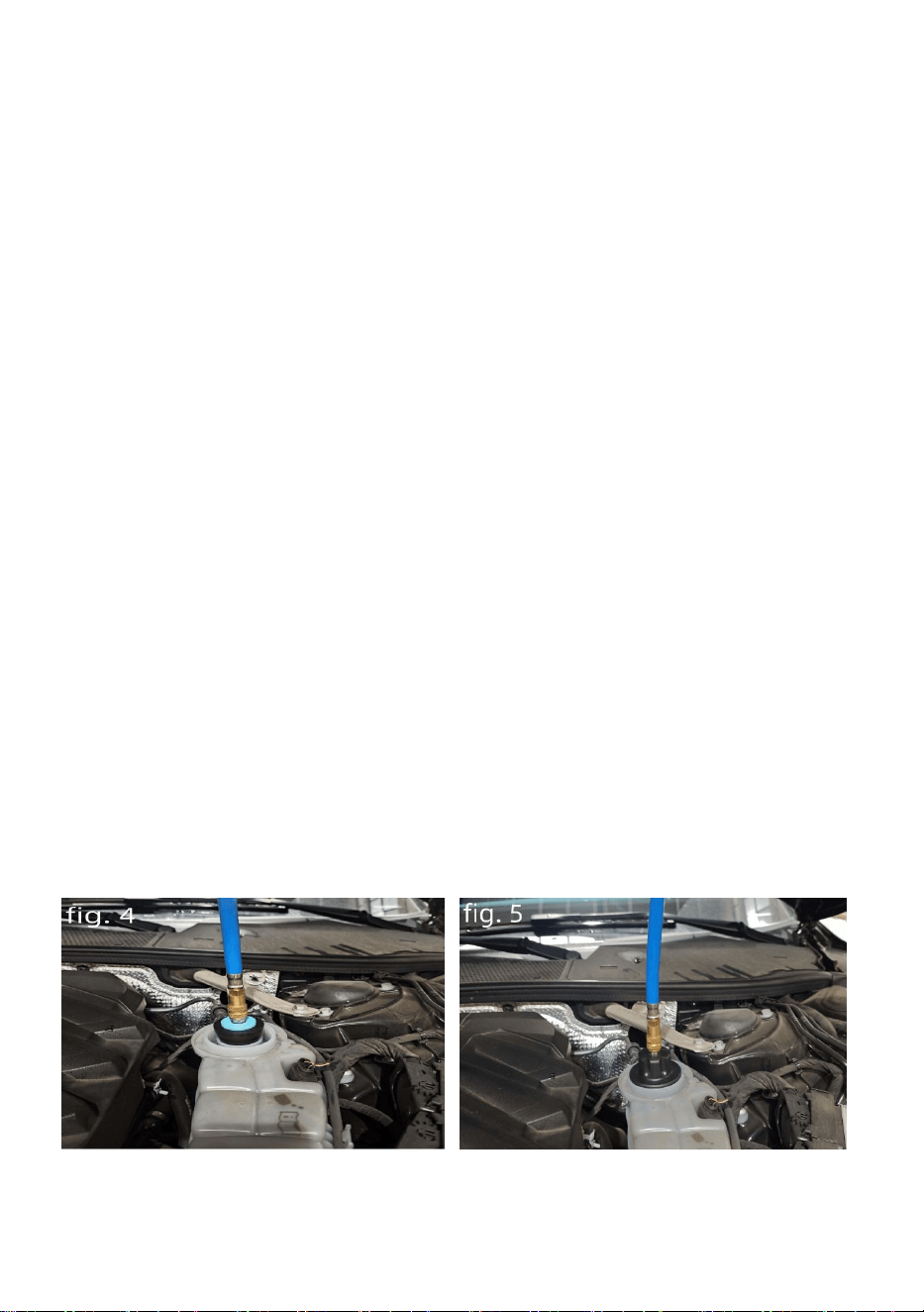
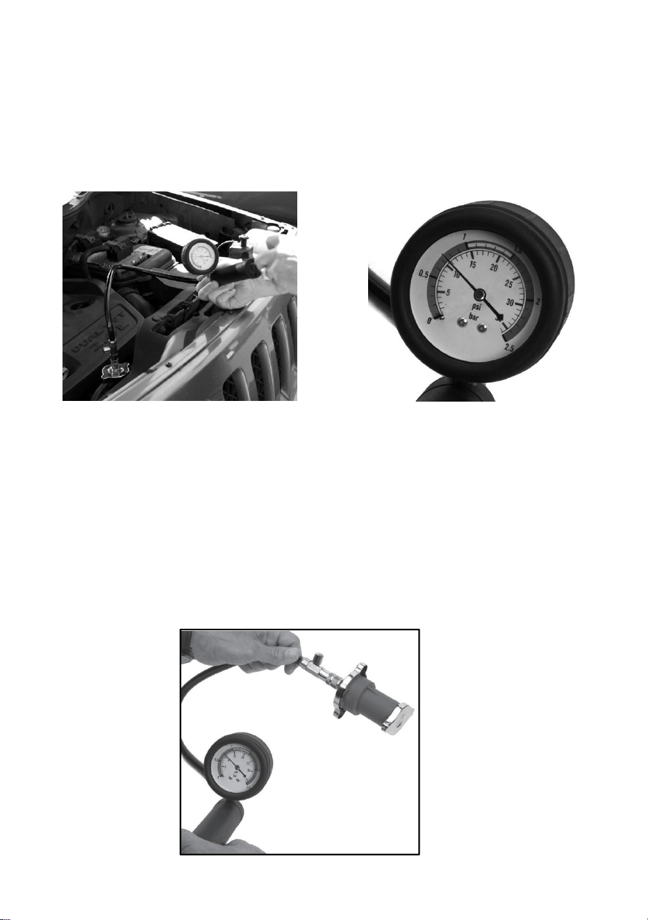
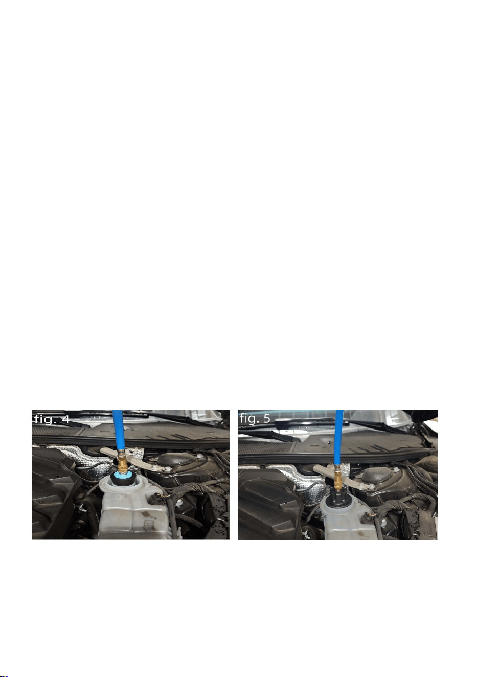
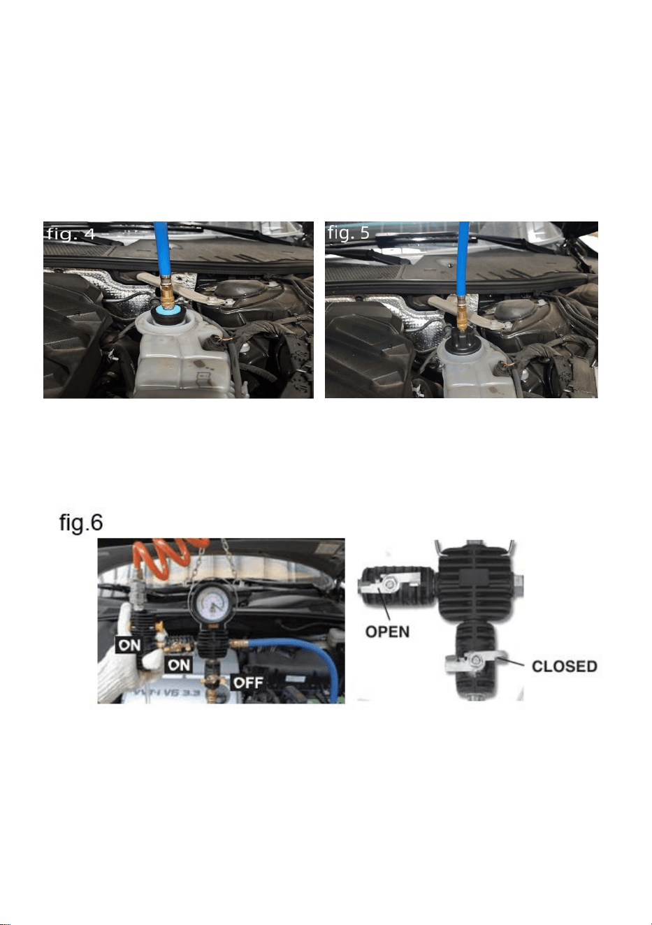
3.3 Connect a suitable vehicle specific adapter or the universal adapter to
the radiator/reservoir.(see fig 4+5)
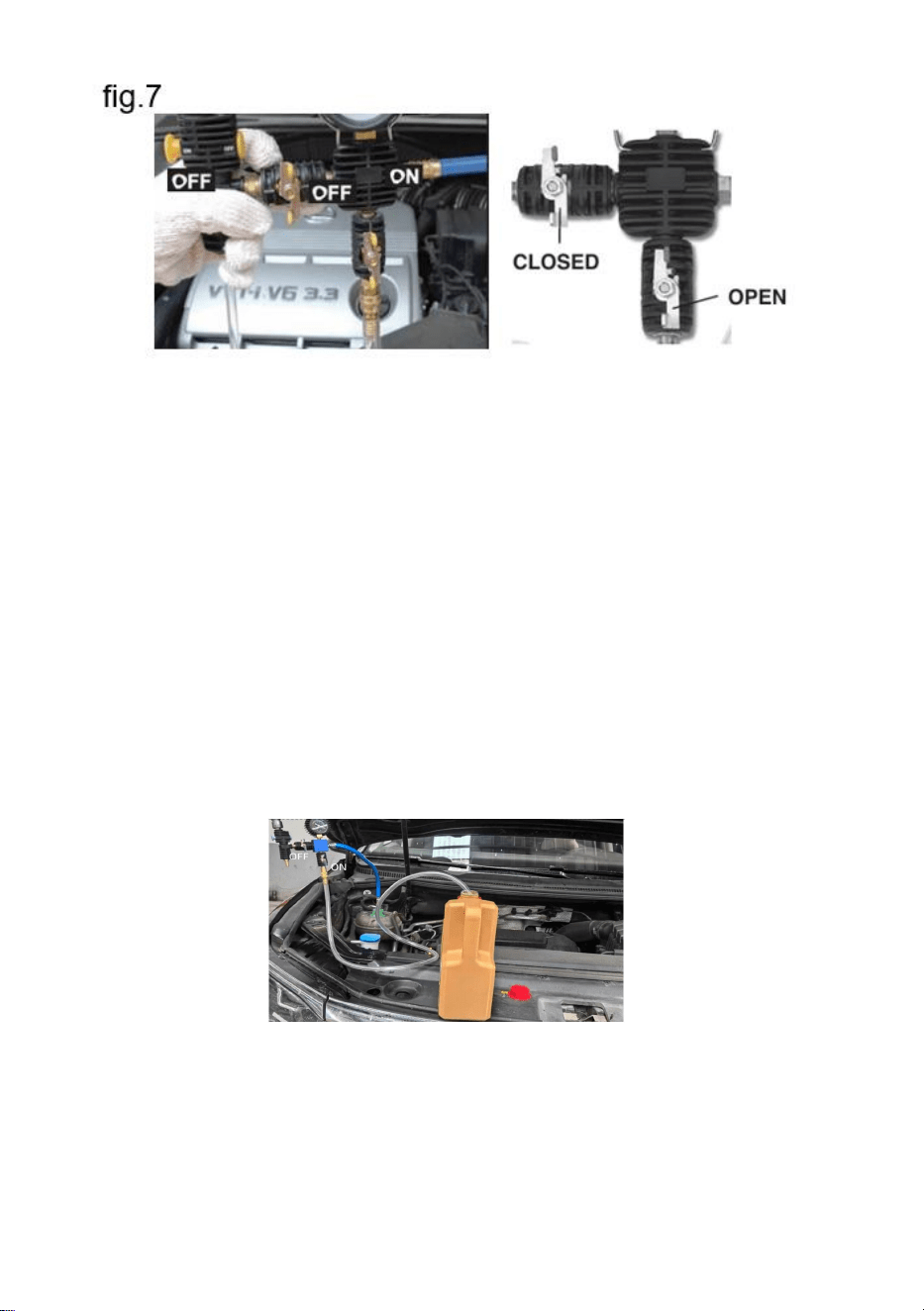
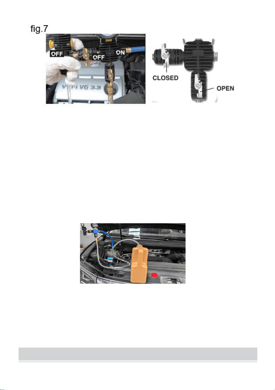
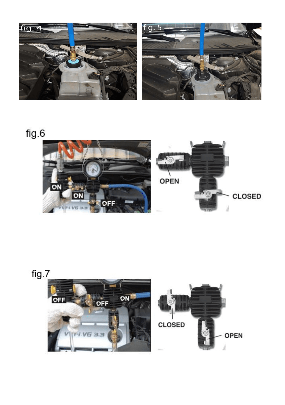
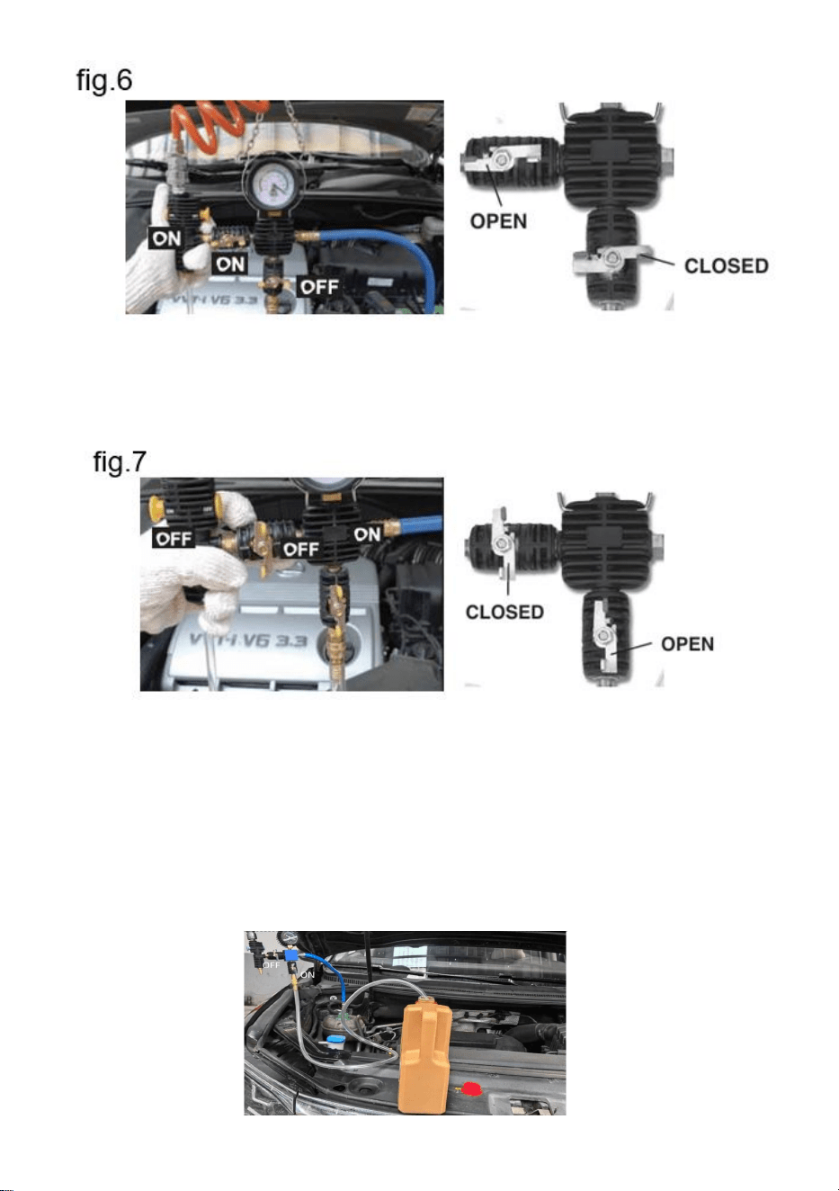
3.4 Be sure that the valve 3 to “ON" And valve 7 to “OFF”Position. (see
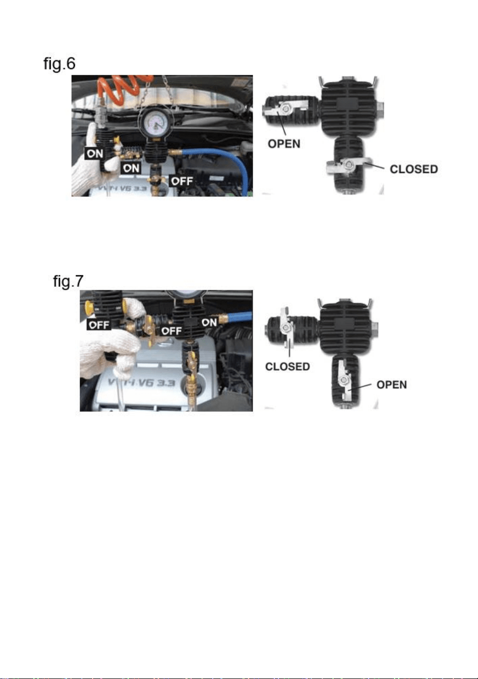
fig.6)
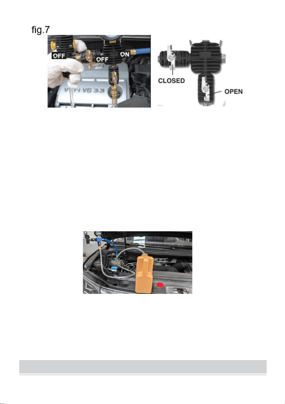
3.5 Connect the vacuum pump to compressed air and switch the "ON/FF"
Switch to "ON.".Switch valve NO.3 to "OFF".(see fig.7) lf a pressure
of20-25inhg(60-50cmhg)is reached.
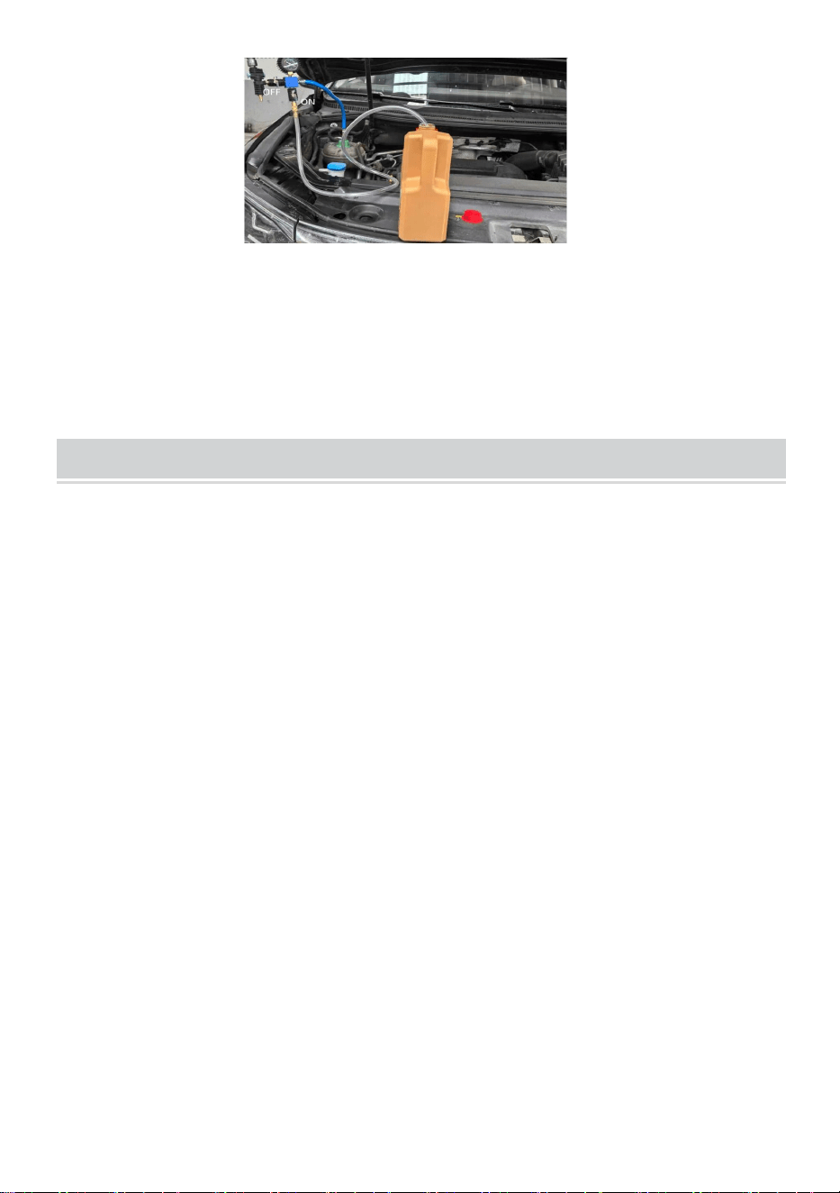
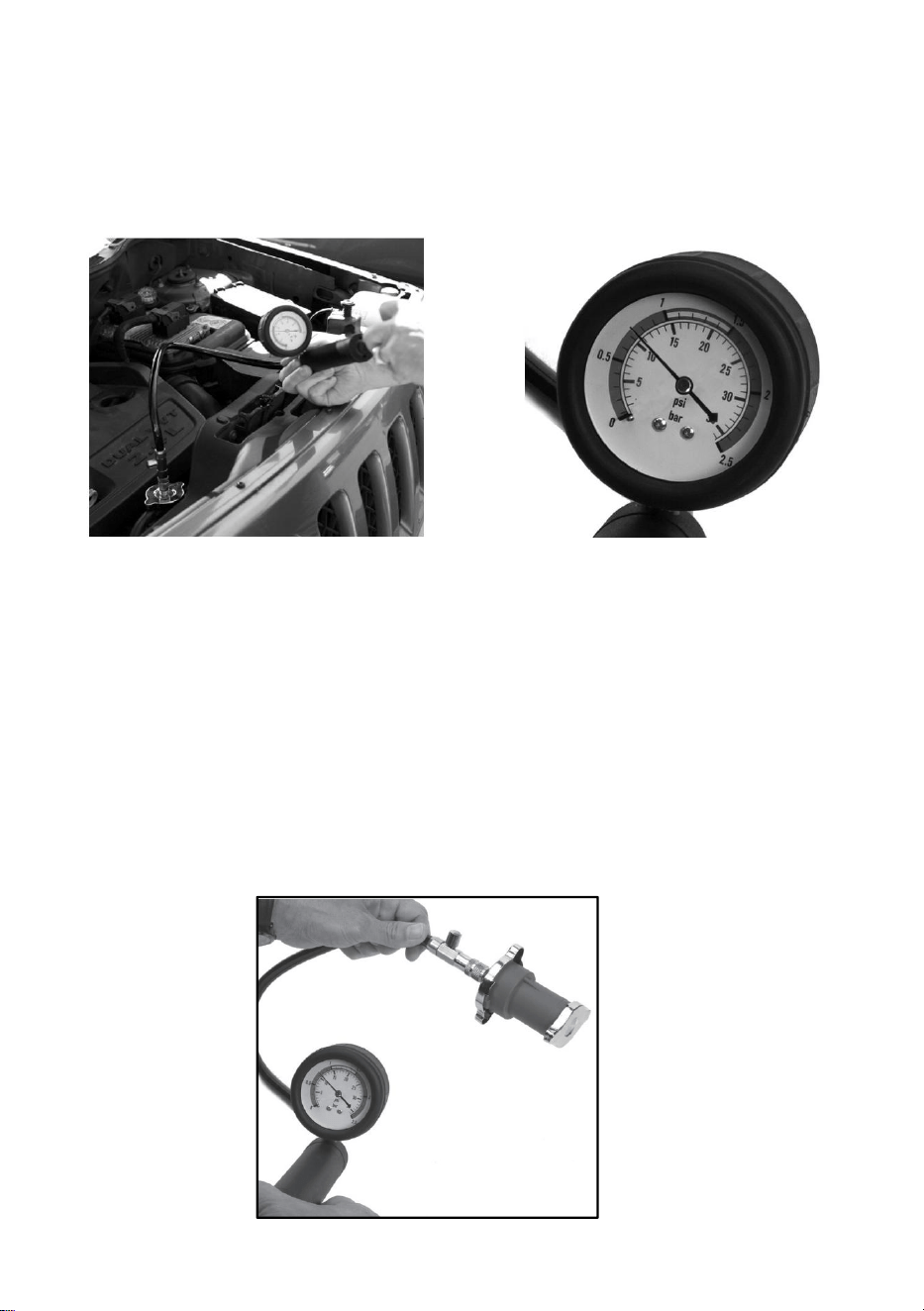
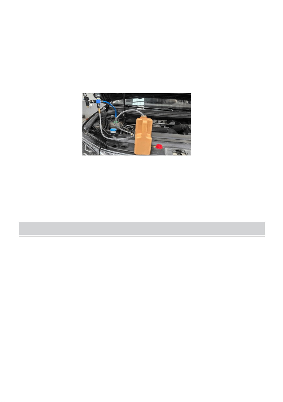
3.6 Connect the coolant hose to the vacuum pump and put the hose into
the container filled with coolant.
3.7 Make sure that valve NO.3 is in the "OFF" Position before the coolant is
topped up.
3.8 Make sure that the hose is filled with coolant.
3.9 Switch valve NO.7 to "ON": the coolant be sucked out of the container.
(see fig. 9)
3.10 lf the pressure indicator has dropped to "0", the cooler should be
sufficiently filled: otherwise, the procedure can be repeated.
IMPORTANT NOTE
These instructions do not replace the service literature. You may find
additional information in the service-literature. For all tests, vehicle-specific
data should be present; without this data, adequate results are not
ensured.
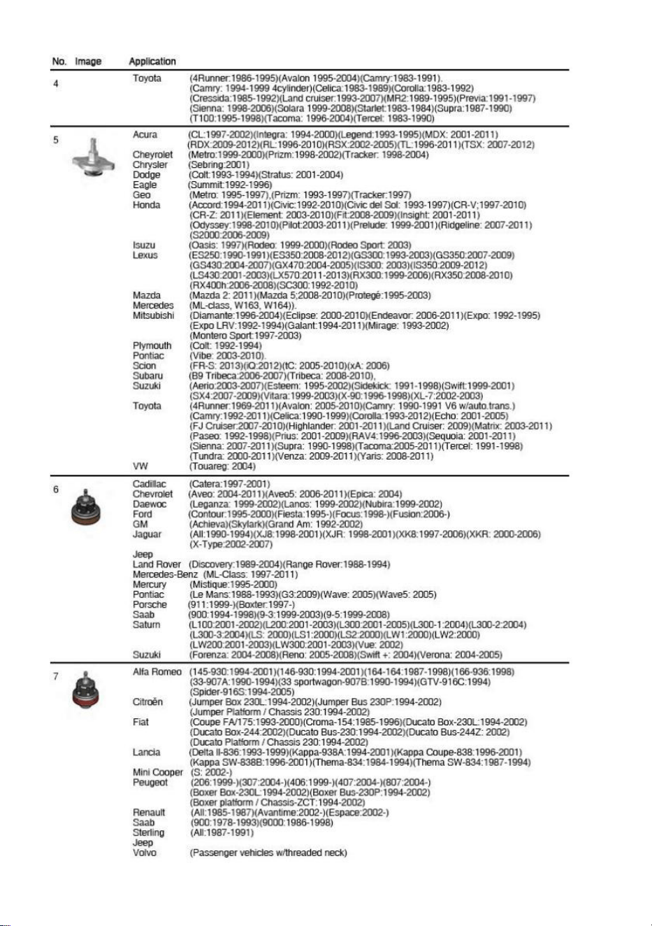
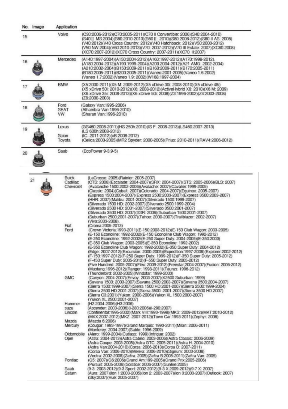
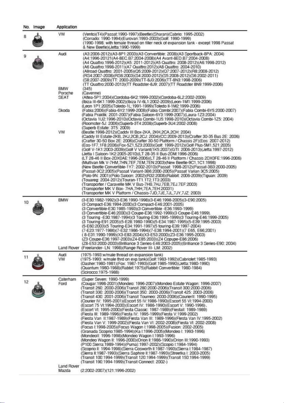
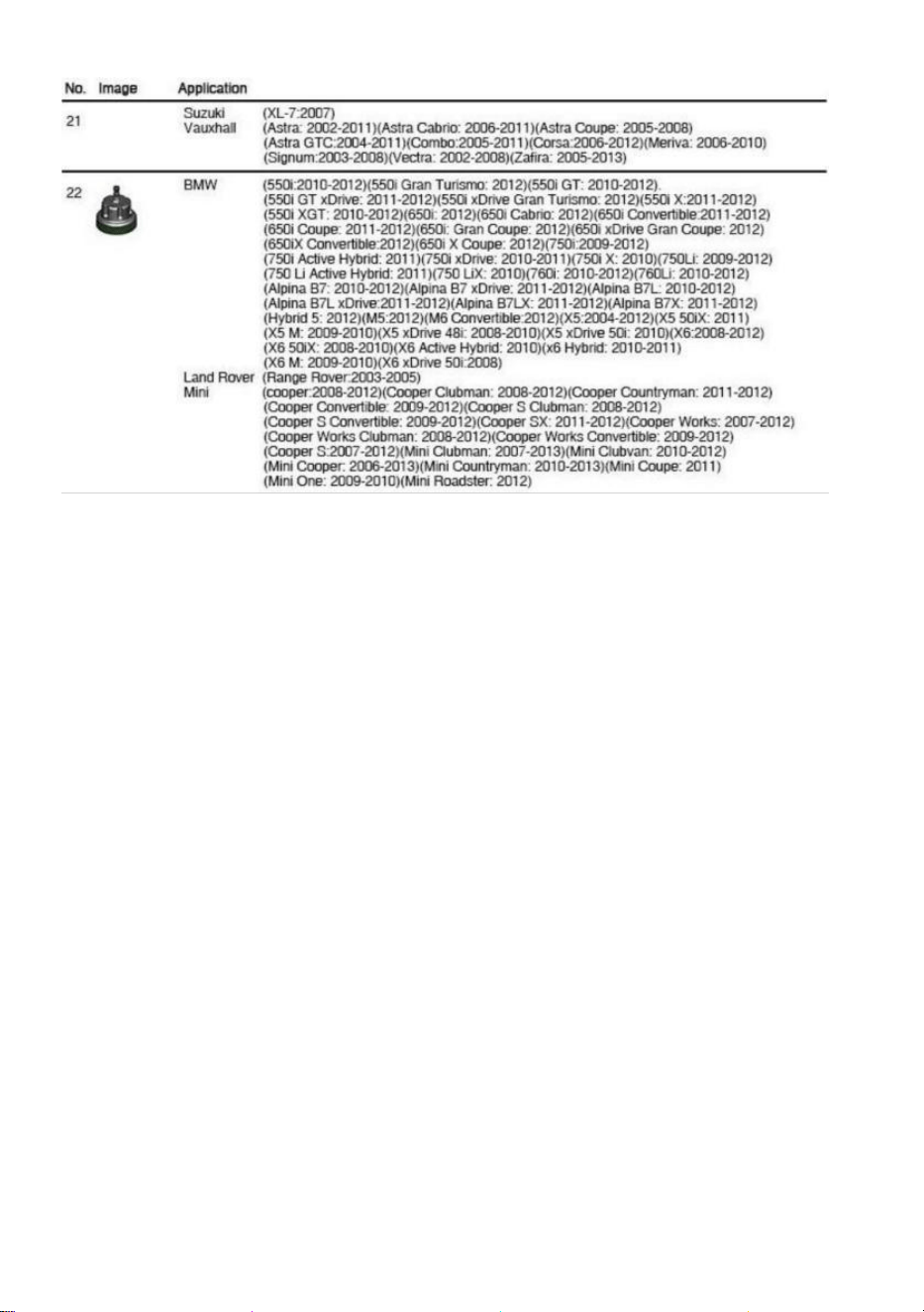
SUITABLE VEHICLE MODELS


Manufacturer: Shanghaimuxinmuyeyouxiangongsi
Address: Shuangchenglu 803nong11hao1602A-1609shi, baoshanqu,
shanghai 200000 CN.
Imported to AUS: SIHAO PTY LTD. 1 ROKEVA STREETEASTWOOD
NSW 2122 Australia
Imported to USA: Sanven Technology Ltd. Suite 250, 9166 Anaheim
Place, Rancho Cucamonga, CA 91730


Tester ciśnienia płynu
chłodzącego/uzupełnianie podciśnieniowe
płynu chłodzącego
Modele: YS-01205A,YS-01205B

Centrum wsparcia
VEVOR
YS-01205A YS-01205B


Modele: YS-01205A,YS-01205B
To jest oryginalna instrukcja obsługi. Przed użyciem prosimy o dokładne
zapoznanie się z treścią instrukcji. Firma VEVOR zastrzega sobie prawo
do jednoznacznej interpretacji niniejszej instrukcji obsługi. Wygląd
produktu zależy od stanu, w jakim go otrzymali Państwo. Prosimy o
wyrozumiałość, ale nie będziemy Państwa ponownie informować o
aktualizacjach technologicznych lub oprogramowania naszego produktu.
Coolant Pressure Tester/
Coolant Vacuum Refill
SPECIFICATION
Model
YS-01205A
YS-01205B
Zakres ciśnienia
0~2,5 bara/0~35 psi
Zakres próżni
przyrządu
-76~0 cmHg(-30~0 caliHg)
Materiał wkładu
próżniowego
chłodziwa
Aluminium i plastik
z miedzią
Plastik z miedzią
PACKAGE LIST
NIE.
Część
Zdjęcie
Specyfikacja
ILOŚĆ
1
Pompa
ciśnieniowa płynu
chłodzącego
/
1
2
Uzupełnianie
płynu
chłodzącego za
pomocą
odkurzacza
adapter dyszy
podczerwieni US
1
3
3 # Testcap
/
1
4
4 # Testcap
/
1

5
5 # Testcap
/
1
6
6# Testcap
Średnica :
M50*3,5
English10buds
1
7
7 # Testcap
Średnica :
M45*3,5
English9buds
1
8
8 # Testcap
Średnica :
M57*3angielski9
pąki
1
9
9 # Testcap
Średnica :
M62*3angielski
9buds
1
10
10 # Testcap
Średnica :
M49*4,5
English6buds
1
11
11 # Testcap
Średnica :
M46*3,5
English9buds
1
12
12 # Testcap
Średnica :
M51*3angielski
8buds
1
13
13 # Testcap
Średnica :
M61*4angielski
6 pąków
1
14
14 # Testcap
Średnica : M53* 3
angielskie 9
pąków
1

15
15# nakrętka
testowa
Średnica : M48*
2,5 angielskie 9
pąków
1
16
16# czapka
testowa
Średnica : M45*3
angielskie 8
pąków
1
17
17# czapka
testowa
Średnica : M50*3
angielskie 8
pąków
1
18
18# nakrętka
testowa
Średnica : M47*3
angielskie 9
pąków
1
19
19# Nakrętka
testowa
Średnica : M34* 3
1
20
20# nakrętka
testowa
Średnica : M44*3
angielskie 8
pąków
1
21
21# Nakrętka
testowa
Średnica : M52* 3
angielskie 9
pąków
1
22
22# Nakrętka
testowa
Średnica : M44*3
angielskie 8
pąków
1
23
Uniwersalny
adapter stożkowy
Interfejs: M10
1
24
Termometr
Zakres : 0-200°
Temperatura
32-400°C
1
25
Klucz nasadowy
/
1
26
Pierścień
uszczelniający
/
15
27
Adapter dyszy
powietrznej
Norma europejska
1
28
Wąż płynu
chłodzącego
1,5 m
×Φ
12 mm,
0,4 m
×Φ
9 mm
2
29
PTFE pas
/
/
1
30
Podręcznik
/
1
SECURITY&WARNINGS

6. Podczas korzystania z tego sprzętu należy przestrzegać zasad,
przepisów i warunków bezpieczeństwa obowiązujących w warsztacie.
7. OSTRZEŻENIE! Przed wymianą akcesoriów lub serwisowaniem należy
odłączyć urządzenie od dopływu powietrza.
8. Utrzymuj sprzęt w dobrym stanie i wymieniaj wszystkie uszkodzone lub
zużyte części.
9. Używaj wyłącznie oryginalnych części. Nieautoryzowane części mogą
być niebezpieczne i unieważnią gwarancję.
10. UWAGA! Sprawdź, czy ciśnienie powietrza jest prawidłowe i NIE
przekracza 100 psi.
Badanie , zrozumieć I podążać Wszystko instrukcje pod warunkiem , że
z Ten
produkt . Czytać te instrukcje ostrożnie
zanim instalowanie , operacyjny ,
serwisowanie Lub naprawianie Ten
narzędzie. Trzymać te instrukcje W A
bezpieczna dostępny miejsce.
PRZEZNACZONY UŻYWAĆ Z THE NARZĘDZIE
Ten zestaw Jest zaprojektowany Do test Do przeciek W pojazd chłodzenie
systemy, w tym kaloryfer czapki, I Do szybki zmiana z płyn chłodzący tylko. Używać
Jak przeznaczony tylko.
Przed użyciem narzędzia należy zawsze uważnie przeczytać instrukcję.
Zestaw narzędzi przeznaczony jest wyłącznie do konserwacji układu
chłodzenia.
Upewnij się, że miejsce pracy jest odpowiednio oświetlone.
Trzymaj dzieci i osoby nieupoważnione z dala od miejsca pracy.
Utrzymuj miejsce pracy w czystości i porządku, suche i wolne od
Wear eye
protection
Refer to
instructions
Wear protective
gloves
Wear safety
footwear
Wear protective
clothing

niepożądanych materiałów.
NIE WOLNO pozwalać osobom nieprzeszkolonym na korzystanie z
tego zestawu narzędzi.
Zawsze należy nosić okulary ochronne spełniające normy OSHA i ANSI
Z87.1.
Podczas pracy z narzędziem należy zawsze nosić rękawice.
Zawsze noś ochronę słuchu.
Sprzedaż: Klienci powinien podążać lokalny regulamin Do uchwyt
używane lub odpady części .
Do nie usunąć ten kaloryfer czapka Lub płyn chłodzący butelka czapka
Kiedy ten silnik Jest gorący Lub w trakcie operacji temperatura.
Pozwalać ten silnik Fajny pierwszy . Porażka Do uwaga Ten ostrzeżenie
może powodować szkoda i/lub osobisty obrażenia.
ZANIM UŻYWAĆ
DO NIE WYRZUCAJ-DAJ DO UŻYTKOWNIKA
Płyn chłodzący Móc rozpylać na zewnątrz.
Zanim demontaż ten pompa Lub ten adapter, uwolnienie ten ciśnienie.
Sprawdzać ten chłodzenie płyn Po ten ciśnienie test Lub naprawa
do prawidłowy poziom i mróz ochrona.
Brać pielęgnacja Kiedy pracujący NA działanie silniki, Luźny Lub
workowaty odzież Móc zostać złapanym W obracający się silnik
strony.
INSTRUCTIONS
Tester ciśnienia płynu chłodzącego
3. Test szczelności układu chłodzenia
1.1 Zdejmowanie oryginalnego korka chłodnicy z chłodnicy lub zbiornika
wyrównawczego.
1.2 Wybierz odpowiedni adapter z zestawu testowego i podłącz go do
chłodnicy lub zbiornika wyrównawczego.
1.3 Teraz podłącz pompę ręczną (1) do adaptera.
1.4 Naciskaj pompę testową, aż ciśnienie wyniesie od 10 do 15 psi (patrz
rysunek 1+2)
OSTROŻNOŚĆ : Unikaj ciśnienia 35 psi lub większego!
Sprawdź manometr. Jeśli wyświetlana wartość spadnie, wyciek znajduje
się w układzie chłodzenia.
Układ chłodzenia ma nieszczelność, jeśli występuje spadek ciśnienia lub
utrata wody.
Rys.1 Rys.2
4. Test szczelności korka chłodnicy
2.1 Zdjąć oryginalny korek chłodnicy.
2.2 Wybierz odpowiedni łącznik 2a lub 2ba i podłącz go do korka chłodnicy.
2.3 Naciśnij pompkę testową kilka razy i obserwuj manometr. Spadek
ciśnienia następuje , jeżeli nakrętka jest uszkodzona. (patrz rys. 3)
2.4 Porównaj zmierzone wartości ciśnienia ze standardowym ciśnieniem
na korku chłodnicy.
Rys.3

KONSERWACJA / PRZECHOWYWANIE
Podłącz adapter testowy do szybkozłącza ręcznej pompki ciśnieniowej,
a następnie naciśnij pompkę ciśnieniową kilka razy, aby wypchnąć
resztki wody z adaptera testowego.
W celu nasmarowania tłoka pompki ręcznej wlej olej pneumatyczny do
otworu wentylacyjnego w pompce ręcznej.
Uzupełnianie płynu chłodzącego za pomocą
odkurzacza
1. DOPŁYW POWIETRZA
1.1 Podczas podłączania do źródła powietrza należy upewnić się, że
zawór jest zamknięty.
1.2 Będziesz potrzebować ciśnienia powietrza wynoszącego 90 psi i
przepływu powietrza zgodnego ze specyfikacją .
2 PRZYGOTOWANIE
2. 1 Ustaw sterowanie ogrzewaniem pojazdu w pozycji „ Wł . ” i/lub
„Gorące”. Spuść i przepłucz układ chłodzenia.
2.2 Sprawdź wszystkie elementy układu chłodzenia i napraw lub wymień
te, które nie nadają się do użytku.
2. 3 Przygotuj odpowiednią mieszankę płynu chłodzącego (patrz instrukcja
obsługi pojazdu). Wymieszaj o 10% więcej płynu niż wynosi objętość
układu, aby zapewnić, że wąż wlewowy będzie zawsze zanurzony .
2.4 Podłącz przedmiot do układu powietrznego w sposób opisany powyżej.
3 NAPEŁNIANIE UKŁADU CHŁODZENIA
3.1 Otwórz maskę i zamocuj pompę próżniową za pomocą haków na
masce.
3.2 Zdjąć korek chłodnicy lub zbiornika wyrównawczego. Spuścić
całkowicie płyn chłodzący w odpowiednim miejscu. Procedurę można
znaleźć w dokumentacji serwisowej danego pojazdu.
3.3 Podłącz odpowiedni adapter do konkretnego pojazdu lub adapter
uniwersalny do chłodnica/zbiornik (patrz rys. 4+5)

3.4 Upewnij się, że zawór 3 jest w pozycji „ON”, a zawór 7 w pozycji „
OFF” (patrz rys. 6).
3.5 Podłącz pompę próżniową do sprężonego powietrza i przełącz
przełącznik „ON/OFF” na „ON”. Zawór przełączający nr 3 należy
ustawić na „OFF” (patrz rys. 7) , jeśli osiągnięte zostanie ciśnienie 20–
25 inhg (60–50 cmhg).
3.6 Podłącz wąż płynu chłodzącego do pompy próżniowej i umieść wąż w
pojemniku wypełnionym płynem chłodzącym.
3.7 Przed uzupełnieniem płynu chłodzącego upewnij się, że zawór nr 3
znajduje się w pozycji „WYŁ”. w górę.
3.8 Upewnij się, że wąż jest napełniony płynem chłodzącym.
3.9 Zawór przełączający nr 7 w pozycję „ON”: płyn chłodzący zostanie
odessany z pojemnik . (patrz rys. 9)
3.10 Jeżeli wskaźnik ciśnienia spadł do „0”, chłodnica powinna być
wystarczająco wypełnione: w przeciwnym wypadku procedurę można
powtórzyć .
WAŻNA UWAGA
Niniejsza instrukcja nie zastępuje dokumentacji serwisowej. Dodatkowe
informacje można znaleźć w dokumentacji serwisowej. Do wszystkich
testów wymagane są dane dotyczące konkretnego pojazdu; bez nich nie
można zagwarantować uzyskania prawidłowych wyników.

SUITABLE VEHICLE MODELS


Producent: Shanghaimuxinmuyeyouxiangongsi
Adres: Shuangchenglu 803nong11hao1602A-1609shi, baoshanqu,
szanghaj 200000 CN.
Importowane do AUS: SIHAO PTY LTD. 1 ROKEVA
STREETEASTWOOD
NSW 2122 Australia
Importowane do USA: Sanven Technology Ltd. Suite 250, 9166 Anaheim
Miejsce, Rancho Cucamonga, CA 91730


Kühlmitteldruckprüfer/Kühlmittelvakuum-
Nachfüllung
Modell: YS-01205A,YS-01205B
VEVOR-Supportcenter
YS-01205A YS-01205B


Modell: YS-01205A,YS-01205B
Dies ist die Originalanleitung. Bitte lesen Sie alle Anweisungen sorgfältig
durch, bevor Sie das Gerät in Betrieb nehmen. VEVOR behält sich eine
klare Auslegung unserer Bedienungsanleitung vor. Das Aussehen des
Produkts hängt vom gelieferten Produkt ab. Bitte haben Sie Verständnis
dafür, dass wir Sie nicht erneut über Technologie- oder Software-Updates
informieren.
Coolant Pressure Tester/
Coolant Vacuum Refill

SPECIFICATION
Modell
YS-01205A
YS-01205B
Druckbereich
0~2,5 bar/0~35 psi
Instrumentenvakuum
bereich
-76~0 cmHg (-30~0 inHg)
Material der
Kühlmittel-Vakuum-Na
chfüllung
Aluminium &
Kunststoff mit
Kupfer
Kunststoff mit
Kupfer
PACKAGE LIST
NEIN.
Teil
Bild
Spezifikation
MENGE
1
Kühlmitteldruckpu
mpe
/
1
2
Kühlmittel-Vakuu
m-Nachfüllung
Im Lieferumfang
enthalten:
US-Standard -
Luftdüsenadapter
1
3
3 # Testkappe
/
1
4
4 # Testkappe
/
1
5
5 # Testkappe
/
1

6
6# Testkappe
Durchmesser :
M50*3,5
Englisch10buds
1
7
7 # Testkappe
Durchmesser :
M45*3,5
English9buds
1
8
8 # Testkappe
Durchmesser :
M57*3Englisch9
Knospen
1
9
9 # Testkappe
Durchmesser :
M62*3Englisch
9buds
1
10
10 # Testkappe
Durchmesser :
M49*4,5
Englisch6buds
1
11
11 # Testkappe
Durchmesser :
M46*3,5
English9buds
1
12
12 # Testkappe
Durchmesser :
M51*3Englisch
8buds
1
13
13 # Testkappe
Durchmesser :
M61*4Englisch
6 Knospen
1
14
14 # Testkappe
D iameter :
M53*3 Englisch 9
Knospen
1
15
15#
Prüfkappe
D iameter :
M48*2,5 Englisch
9 Knospen
1

16
16#
Prüfkappe
D iameter :
M45*3 Englisch 8
Knospen
1
17
17#
Prüfkappe
D iameter :
M50*3 Englisch 8
Knospen
1
18
18#
Prüfkappe
D iameter :
M47*3 Englisch 9
Knospen
1
19
19#
Prüfkappe
Durchmesser :
M34* 3
1
20
20#
Testkappe
D iameter :
M44*3 Englisch 8
Knospen
1
21
21#
Prüfkappe
D iameter :
M52*3 Englisch 9
Knospen
1
22
22#
Prüfkappe
D iameter :
M44*3 Englisch 8
Knospen
1
23
Konus-Universal
adapter
Schnittstelle: M10
1

24
Thermometer
Bereich : 0–200 °
C/32-400°F
1
25
Kappenschlüssel
/
1
26
Dichtungsring
/
15
27
Luftdüsenadapter
Europäische
Norm
1
28
Kühlmittelschlauc
h
1,5 m
× Φ
12
mm, 0,4 m
× Φ
9 mm
2
29
PTFE Streifen
/
/
1
30
Handbuch
/
1
SECURITY&WARNINGS

11. Beachten Sie bei der Verwendung dieser Ausrüstung die Gesundheits-
und Sicherheitsvorschriften und -bedingungen der Werkstatt.
12. WARNUNG! Vor dem Wechseln von Zubehör oder Wartungsarbeiten
das Gerät von der Luftzufuhr trennen.
13. Halten Sie die Ausrüstung in gutem Zustand und ersetzen Sie
beschädigte oder abgenutzte Teile.
14. Verwenden Sie nur Originalteile. Nicht autorisierte Teile können
gefährlich sein und führen zum Erlöschen der Garantie.
15. WARNUNG! Stellen Sie sicher, dass der richtige Luftdruck
aufrechterhalten wird und 100 psi NICHT überschreitet.
Studie , verstehen Und folgen alle Anweisungen bereitgestellt
mit Das Produkt .
Lesen diese Anweisungen sorgfältig
vor installieren , Betrieb , Wartung oder
Reparatur Das
Werkzeug. Halten diese Anweisungen In A sicher zugänglich Ort.
BEABSICHTIGT VERWENDEN VON DER WERKZEUG
Das Bausatz Ist entworfen Zu prüfen für Leckage In Fahrzeug Kühlung
Systeme,
einschließlich Kühler Kappen, Und für schnell ändern von Kühlmittel nur. Verwenden
als beabsichtigt nur.
Lesen Sie die Anweisungen vor der Verwendung des Werkzeugs immer
sorgfältig durch.
Dieses Werkzeugset dient ausschließlich der Wartung des
Kühlsystems.
Sorgen Sie für ausreichende Beleuchtung des Arbeitsbereichs.
Halten Sie Kinder und unbefugte Personen vom Arbeitsbereich fern ·
Halten Sie den Arbeitsbereich sauber und ordentlich, trocken und frei
Wear eye
protection
Refer to
instructions
Wear protective
gloves
Wear safety
footwear
Wear protective
clothing

von fremden Materialien
Erlauben Sie NICHT ungeschulten Personen, diesen Werkzeugsatz zu
verwenden.
Tragen Sie immer einen Augenschutz, der den OSHA- und ANSI
Z87.1-Standards entspricht.
Tragen Sie beim Arbeiten mit dem Werkzeug immer Handschuhe.
Tragen Sie immer einen Gehörschutz.
Entsorgung: Kunden sollen folgen lokal Vorschriften Zu handhaben
gebraucht oder Abfall Teile .
Tun nicht entfernen Die Kühler Kappe oder Kühlmittel Flasche Kappe
Wann Die Motor Ist heiß oder bei Betrieb Temperatur. Lassen Die
Motor Cool erster . Fehler Zu beachten Das Warnung kann
verursachen Schaden und/oder persönlich Verletzung.
VOR VERWENDEN
TUN NICHT Wegwerfen-Gib AN DEN BENUTZER
Kühlmittel dürfen Spray aus.
Vor Abbau Die Pumpe oder Die Adapter, freigeben Die Druck.
Überprüfen Die Kühlung Flüssigkeit nach Die Druck prüfen oder
Reparatur an der richtig Ebene und Frost Schutz.
Nehmen Pflege Wann Arbeiten An läuft Motoren, Lose oder
ausgebeult Kleidung dürfen erwischt werden In rotierend Motor
Teile.
INSTRUCTIONS
Kühlmitteldruckprüfer
5. Dichtheitsprüfung des Kühlsystems
1.1 Entfernen des originalen Kühlerdeckels vom Kühler bzw.
Ausgleichsbehälter.
1.2 Wählen Sie aus dem Testset den passenden Adapter aus und
schließen Sie diesen an den Kühler bzw. Ausgleichsbehälter an.
1.3 Schließen Sie nun die Handpumpe (1) an den Adapter an.
1.4 Drücken Sie die Prüfpumpe, bis ein Druck von 10 bis 15 psi erreicht ist
(siehe Abbildung 1+2).
VORSICHT : Vermeiden Sie einen Druck von 35 psi oder mehr!
Überprüfen Sie das Manometer. Sinkt der angezeigte Wert, liegt das Leck
im Kühlsystem vor.
Bei Druckabfall oder Wasserverlust liegt ein Leck im Kühlsystem vor.
Abb.1 Abb.2
6. Kühlerdeckel-Lecktest
2.1 Den originalen Kühlerdeckel entfernen.
2.2 Wählen Sie die passende Verbindung 2a oder 2ba und verbinden Sie
diese mit dem Kühlerdeckel.
2.3 Drücken Sie die Prüfpumpe einige Male und beobachten Sie das
Manometer. Der Druckabfall tritt auf, wenn die Kappe defekt ist (siehe Abb.
3).
2.4 Vergleichen Sie die gemessenen Druckwerte mit dem Standarddruck
des Kühlerdeckels.

Abb.3
WARTUNG / LAGERUNG
Befestigen Sie den Prüfadapter an der Schnellkupplung der
Handdruckpumpe und drücken Sie die Handdruckpumpe einige Male,
um das Restwasser aus dem Prüfadapter zu drücken.
Geben Sie Druckluftöl in die Luftöffnung am Ende der Handpumpe, um
den Kolben der Handpumpe zu schmieren.
Kühlmittel-Vakuum-Nachfüllung
1. LUFTZUFUHR
1.1 Stellen Sie sicher, dass das Ventil beim Anschließen an die
Luftversorgung geschlossen ist.
1.2 Sie benötigen einen Luftdruck von 90 psi und einen Luftstrom
gemäß Spezifikation .
2 VORBEREITUNG
2. 1 Stellen Sie die Heizungssteuerung des Fahrzeugs auf „Ein“ und/oder
„Heiß“. Entleeren und spülen Sie das Kühlmittelsystem .
2 .2 Überprüfen Sie alle Komponenten des Kühlsystems und
reparieren/ersetzen Sie alle nicht funktionsfähigen Teile.
2. 3 Bereiten Sie eine geeignete Kühlmittelmischung vor (siehe
Fahrzeughandbuch). Mischen Sie 10 % mehr als das Systemvolumen, um
sicherzustellen, dass der Einfüllschlauch immer unter Wasser ist .
2.4 Schließen Sie den Artikel wie oben beschrieben an das Luftsystem an.
3- FÜLL-KÜHLSYSTEM
3.1 Öffnen Sie die Haube und befestigen Sie eine Vakuumpumpe mit
Haken an der Haube.
3.2 Kühler- bzw. Ausgleichsbehälterdeckel demontieren. Kühlmittel an
geeigneter Stelle vollständig ablassen. Die Vorgehensweise entnehmen
Sie bitte der fahrzeugspezifischen Serviceliteratur.
3.3 Schließen Sie einen geeigneten fahrzeugspezifischen Adapter oder
den Universaladapter an das Kühler/Behälter. (siehe Abb. 4+5)
3.4 Stellen Sie sicher, dass Ventil 3 auf „EIN“ und Ventil 7 auf „AUS
“ steht. (siehe Abb. 6)
3.5 Schließen Sie die Vakuumpumpe an die Druckluft an und schalten Sie
den Schalter „ON/FF“ auf „EIN“. Schalten Sie Ventil Nr. 3 auf „AUS
“ ( siehe Abb. 7), wenn ein Druck von 20–25 inhg (60–50 cmhg)
erreicht wird.
3.6 Schließen Sie den Kühlmittelschlauch an die Vakuumpumpe an und
stecken Sie den Schlauch in den mit Kühlmittel gefüllten Behälter.
3.7 Stellen Sie sicher, dass Ventil Nr. 3 in der Position „AUS“ steht, bevor
das Kühlmittel nachgefüllt wird hoch.
3.8 Stellen Sie sicher, dass der Schlauch mit Kühlmittel gefüllt ist.
3.9 Ventil Nr. 7 auf „ON“ schalten: Das Kühlmittel wird aus dem Behälter .
(siehe Abb. 9)
3.10 Wenn die Druckanzeige auf "0" gefallen ist, sollte der Kühler
ausreichend ausgefüllt: Andernfalls kann der Vorgang wiederholt werden .
WICHTIGER HINWEIS
Diese Anleitung ersetzt nicht die Serviceliteratur. Weitere Informationen
finden Sie ggf. in der Serviceliteratur. Für alle Prüfungen sollten
fahrzeugspezifische Daten vorliegen, da sonst keine ausreichenden
Ergebnisse gewährleistet sind.
SUITABLE VEHICLE MODELS


Hersteller: Shanghaimuxinmuyeyouxiangongsi
Adresse: Shuangchenglu 803nong11hao1602A-1609shi, baoshanqu,
Shanghai 200000 CN.
Importiert nach AUS: SIHAO PTY LTD. 1 ROKEVA STREETEASTWOOD
NSW 2122 Australien
Importiert in die USA: Sanven Technology Ltd. Suite 250, 9166 Anaheim
Place, Rancho Cucamonga, CA 91730


Testeur de pression du liquide de
refroidissement/Remplissage du vide du
liquide de refroidissement
Modèle : YS-01205A, YS-01205B

Centre
d'assistance
VEVOR
YS-01205A YS-01205B


Modèle : YS-01205A, YS-01205B
Ceci est le mode d'emploi d'origine. Veuillez lire attentivement toutes les
instructions du manuel avant utilisation. VEVOR se réserve le droit
d'interpréter clairement ce manuel d'utilisation. L'apparence du produit
dépend du produit que vous avez reçu. Veuillez nous excuser pour le
retard dans la publication de toute mise à jour technologique ou logicielle
concernant notre produit.
Coolant Pressure Tester/
Coolant Vacuum Refill
SPECIFICATION
Modèle
YS-01205A
YS-01205B
Plage de pression
0~2,5 bar/0~35 psi
Plage de vide des
instruments
-76~0cmHg(-30~0inHg)
Matériau de
remplissage du liquide
de refroidissement
sous vide
Aluminium et
plastique avec
cuivre
Plastique avec
cuivre
PACKAGE LIST
NON.
Partie
Image
Spécification
Qté
1
à pression du
liquide de
refroidissement
/
1
2
Remplissage du
vide du liquide de
refroidissement
à air standard
américain inclus
1
3
3 # Testcap
/
1
4
4 # Testcap
/
1

5
5 # Testcap
/
1
6
6# Testcap
Diamètre :
M50*3,5
Anglais10buds
1
7
7 # Testcap
Diamètre :
M45*3,5
English9buds
1
8
8 # Testcap
Diamètre :
M57*3Anglais9
bourgeons
1
9
9 # Testcap
Diamètre :
M62*3Anglais
9buds
1
10
10 # Testcap
Diamètre :
M49*4,5
English6buds
1
11
11 # Testcap
Diamètre :
M46*3,5
English9buds
1
12
12 # Testcap
Diamètre :
M51*3Anglais
8buds
1
13
13 # Testcap
Diamètre :
M61*4Anglais
6buds
1
14
14 # Testcap
Diamètre : M53* 3
Anglais 9
bourgeons
1

15
Bouchon
d'essai 15#
Diamètre : M48*
2,5 Anglais 9
bourgeons
1
16
Bouchon
d'essai 16#
Diamètre : M45*3
8 bourgeons
anglais
1
17
Bouchon
d'essai 17#
Diamètre : M50*3
8 bourgeons
anglais
1
18
Bouchon
d'essai 18#
Diamètre : M47* 3
Anglais 9
bourgeons
1
19
Bouchon
d'essai 19#
Diamètre : M34* 3
1
20
Bouchon
d'essai 20#
Diamètre : M44*3
8 bourgeons
anglais
1
21
Bouchon
d'essai 21#
Diamètre : M52* 3
Anglais 9
bourgeons
1
22
Bouchon
d'essai 22#
Diamètre : M44*3
8 bourgeons
anglais
1
23
Adaptateur
universel conique
Interface : M10
1
24
Thermomètre
Plage : 0-200°
C/32-400°F
1
25
Clé à molette
/
1
26
Bague
d'étanchéité
/
15
27
Adaptateur de
buse d'air
norme
européenne
1
28
Tuyau de liquide
de
refroidissement
1,5 m
× Φ
12
mm, 0,4 m
× Φ
9 mm
2
29
PTFE bande
/
/
1
30
Manuel
/
1
SECURITY&WARNINGS

16. Respectez les règles, réglementations et conditions de santé et de
sécurité de l'atelier lors de l'utilisation de cet équipement.
17. AVERTISSEMENT ! Débranchez l'alimentation en air avant de
changer les accessoires ou de procéder à l'entretien.
18. Maintenir l’équipement en bon état et remplacer toute pièce
endommagée ou usée.
19. Utilisez uniquement des pièces d'origine. L'utilisation de pièces non
autorisées peut être dangereuse et annulera la garantie.
20. ATTENTION ! Vérifiez que la pression d'air est maintenue à un niveau
correct et qu'elle NE dépasse PAS 100 psi.
Étude , comprendre et suivre tous instructions fourni
avec ce produit . Lire ces
instructions soigneusement
avant installation , en fonctionnement , entretien ou
réparation ce
outil. Garder ces instructions dans un sûr accessible lieu.
DESTINÉ UTILISER DE LE OUTIL
Ce trousse est conçu à test pour fuite dans véhicule refroidissement
systèmes, y
compris radiateur casquettes, et pour rapide changement de liquide de
refroidissement seulement. Utiliser comme destiné seulement.
Lisez toujours attentivement les instructions avant d’utiliser l’outil.
Cette trousse à outils est destinée uniquement à l'entretien du système
de refroidissement.
Assurez-vous que la zone de travail dispose d’un éclairage adéquat.
Tenir les enfants et les personnes non autorisées éloignés de la zone de
travail ·
Gardez la zone de travail propre et rangée, sèche et exempte de
Wear eye
protection
Refer to
instructions
Wear protective
gloves
Wear safety
footwear
Wear protective
clothing

matériaux non liés
NE PAS permettre à des personnes non formées d’utiliser cette trousse
à outils.
Portez toujours une protection oculaire conforme aux normes OSHA et
ANSI Z87.1.
Portez toujours des gants lorsque vous travaillez avec l’outil.
Portez toujours une protection auditive.
Élimination: Clients devrait suivre locale règlements à poignée utilisé ou
déchet pièces .
Faire pas retirer le radiateur capuchon ou liquide de refroidissement
bouteille capuchon quand le moteur est chaud ou en fonctionnement
température. Laisser le moteur cool premier . Échec à attention ce
avertissement peut causer dommage et/ou personnel blessure.
AVANT UTILISER
FAIRE PAS JETER-DONNER À L' UTILISATEUR
liquide de refroidissement peut pulvérisation dehors.
Avant démantèlement le pompe ou le adaptateur, libérer le pression.
Vérifier le refroidissement fluide après le pression test ou réparation de
la correct niveau et le gel protection.
Prendre soins quand fonctionnement sur en cours d'exécution
moteurs, Lâche ou bouffant vêtements peut se faire prendre dans
tournant moteur parties.
INSTRUCTIONS
Testeur de pression du liquide de refroidissement
7. Test de fuite du système de refroidissement
1.1 Retrait du bouchon de radiateur d'origine du radiateur ou du vase
d'expansion.
1.2 Choisissez l'adaptateur approprié dans le kit de test et connectez-le au
radiateur ou au vase d'expansion.
1.3 Connectez maintenant la pompe à main (1) à l'adaptateur.
1.4 Appuyez sur la pompe de test jusqu'à atteindre une pression de 10 à
15 psi (voir figure 1+2)
PRUDENCE : Évitez une pression de 35 psi ou plus !
Vérifiez le manomètre. Si la valeur affichée diminue, la fuite provient du
système de refroidissement.
Le système de refroidissement présente une fuite en cas de chute de
pression ou de perte d'eau.
Fig.1 Fig.2
8. Test de fuite du bouchon du radiateur
2.1 Retirez le bouchon du radiateur d'origine.
2.2 Choisissez le joint approprié 2a ou 2ba et connectez-le au bouchon du
radiateur.
2.3 Appuyez plusieurs fois sur la pompe de test et observez le manomètre.
La pression chute si le bouchon est défectueux. (voir fig.3)
2.4 C omparez les valeurs de pression mesurées avec la pression
standard du bouchon du radiateur.

Fig.3
ENTRETIEN / STOCKAGE
Fixez l'adaptateur de test au raccord rapide de la pompe à pression
manuelle, puis appuyez plusieurs fois sur la pompe à pression manuelle
pour pousser l'eau restante hors de l'adaptateur de test.
Déposez de l'huile pneumatique dans le trou d'air de l'extrémité de la
pompe à main pour lubrifier le piston de la pompe à main.
Remplissage du vide du liquide de refroidissement
1. ALIMENTATION EN AIR
1 .1 Assurez-vous que la vanne est fermée lors du raccordement à
l’alimentation en air.
1.2 Vous aurez besoin d'une pression d'air de 90 psi et d'un débit d'air
conforme aux spécifications .
2 PRÉPARATION
2. 1 Réglez la commande de chauffage du véhicule sur « Marche » et/ou
« Chaud ». Vidangez et rincez le système de refroidissement .
2 .2 Inspectez tous les composants du système de refroidissement et
réparez/remplacez tous les éléments inutilisables.
2. 3 Préparer un mélange de liquide de refroidissement adapté (voir le
manuel du véhicule). Mélanger 10 % de plus que le volume du système
pour garantir que le tuyau de remplissage soit toujours immergé.
2 .4 Connectez l’article au système d’air comme décrit ci-dessus.
SYSTÈME DE REFROIDISSEMENT À 3 REMPLISSAGES
3.1 Ouvrez le capot et fixez une pompe à vide avec des crochets sur le
capot.
3.2 Retirer le bouchon du radiateur ou du réservoir. Vidanger
complètement le liquide de refroidissement à un endroit approprié. La
procédure est décrite dans la documentation d'entretien spécifique au
véhicule.
3.3 Connectez un adaptateur spécifique au véhicule approprié ou
l'adaptateur universel au radiateur/réservoir. (voir fig. 4+5)
3.4 Assurez-vous que la vanne 3 est sur « ON » et la vanne 7 sur « OFF ».
(voir fig. 6)
3.5 Connectez la pompe à vide à l'air comprimé et actionnez l'interrupteur
« ON/FF » sur « ON ». Commutez la vanne N° 3 sur « OFF » ( voir fig. 7)
si une pression de 20-25 inhg (60-50 cmhg) est atteinte.
3.6 Connectez le tuyau de liquide de refroidissement à la pompe à vide et
placez le tuyau dans le récipient rempli de liquide de refroidissement.
3.7 Assurez-vous que la vanne n°3 est en position « OFF » avant de faire
le plein de liquide de refroidissement en haut.
3.8 Assurez-vous que le tuyau est rempli de liquide de refroidissement.
3.9 Commutez la vanne n°7 sur « ON » : le liquide de refroidissement est
aspiré hors du récipient . (voir fig. 9)
3.10 Si l'indicateur de pression est tombé à « 0 », le refroidisseur doit être
suffisamment rempli : sinon, la procédure peut être répétée .
NOTE IMPORTANTE
Ces instructions ne remplacent pas la documentation d'entretien. Vous y
trouverez des informations complémentaires. Pour tous les tests, les
données spécifiques au véhicule doivent être présentes ; sans ces
données, les résultats ne sont pas satisfaisants.
SUITABLE VEHICLE MODELS


Fabricant : Shanghaimuxinmuyeyouxiangongsi
Adresse : Shuangchenglu 803nong11hao1602A-1609shi, baoshanqu,
Shanghai 200 000 CN.
Importé en Australie : SIHAO PTY LTD. 1 ROKEVA STREET, ASTWOOD
NSW 2122 Australie
Importé aux États-Unis : Sanven Technology Ltd. Suite 250, 9166
Anaheim
Lieu, Rancho Cucamonga, CA 91730


Koelvloeistofdruktester/koelvloeistof
vacuüm bijvullen
Model: YS-01205A,YS-01205B
VEVOR
Ondersteuningscentrum

YS-01205A YS-01205B


Model: YS-01205A,YS-01205B
Dit is de originele handleiding. Lees alle instructies zorgvuldig door voordat
u het product gebruikt. VEVOR behoudt zich het recht voor om de
gebruiksaanwijzing duidelijk te interpreteren. Het uiterlijk van het product is
afhankelijk van het product dat u hebt ontvangen. Neemt u het ons niet
kwalijk dat we u niet meer op de hoogte stellen van eventuele
technologische of software-updates voor ons product.
Coolant Pressure Tester/
Coolant Vacuum Refill
SPECIFICATION
Model
YS-01205A
YS-01205B
Drukbereik
0~2,5 bar/0~35 psi
Instrument
vacuümbereik
-76~0 cm Hg (-30~0 in Hg)
Materiaal van
koelvloeistof
vacuümvulling
Aluminium &
kunststof met koper
Kunststof met
koper
PACKAGE LIST
NEE.
Deel
Afbeelding
Specificatie
AANTAL
1
Koelmiddeldrukpo
mp
/
1
2
Koelvloeistof
vacuüm bijvullen
Inclusief US
Standard A-
luchtmondstukada
pter
1
3
3 # Testdop
/
1
4
4 # Testdop
/
1
5
5 # Testdop
/
1

6
6# Testdop
Diameter :
M50*3.5
Engels10buds
1
7
7 # Testdop
Diameter :
M45*3.5
English9buds
1
8
8 # Testdop
Diameter :
M57*3Engels9
knoppen
1
9
9 # Testdop
Diameter :
M62*3Engels
9knoppen
1
10
10 # Testdop
Diameter :
M49*4.5
English6buds
1
11
11 # Testdop
Diameter :
M46*3.5
English9buds
1
12
12 # Testdop
Diameter :
M51*3Engels
8 knoppen
1
13
13 # Testdop
Diameter :
M61*4Engels
6 knoppen
1
14
14 # Testdop
Diameter : M53* 3
Engels 9 knoppen
1
15
15# Testdop
Diameter : M48*
2.5 Engelse 9
knoppen
1
16
16# Testdop
Diameter : M45*3
Engels 8 knoppen
1
17
17# Testdop
Diameter : M50*3
Engels 8 knoppen
1
18
18# Testdop
Diameter : M47* 3
Engels 9 knoppen
1
19
19# Testdop
Diameter : M34* 3
1
20
20# Testdop
Diameter : M44*3
Engels 8 knoppen
1
21
21# Testdop
Diameter : M52* 3
Engels 9 knoppen
1
22
22# Testdop
Diameter : M44*3
Engels 8 knoppen
1
23
Universele
kegeladapter
Interface: M10
1

24
Thermometer
Bereik : 0-200°
C/32-400°F
1
25
Dopsleutel
/
1
26
Afdichtring
/
15
27
Luchtmondstuka
dapter
Europese norm
1
28
Koelvloeistofslan
g
1,5 m
× Φ
12
mm, 0,4 m
× Φ
9 mm
2
29
PTFE strip
/
/
1
30
Handmatig
/
1
SECURITY&WARNINGS

21. Volg de gezondheids- en veiligheidsregels, voorschriften en
voorwaarden van de werkplaats wanneer u deze apparatuur gebruikt.
22. WAARSCHUWING! Koppel het apparaat los van de luchttoevoer
voordat u accessoires verwisselt of onderhoud pleegt.
23. Zorg ervoor dat de apparatuur in goede staat verkeert en vervang
beschadigde of versleten onderdelen.
24. Gebruik alleen originele onderdelen. Niet-geautoriseerde onderdelen
kunnen gevaarlijk zijn en maken de garantie ongeldig.
25. WAARSCHUWING! Controleer of de juiste luchtdruk wordt
gehandhaafd en NIET hoger is dan 100 psi.
Studie , begrijpen En volgen alle instructies mits
met dit product . Lezen deze
instructies voorzichtig
voor installeren , in werking , onderhoud of repareren dit
hulpmiddel. Houden deze instructies in A veilig toegankelijk plaats.
BEDOELD GEBRUIK VAN DE HULPMIDDEL
Dit set is ontworpen naar test voor lekkage in voertuig koeling
systemen,
inbegrepen radiator doppen, En voor snel wijziging van koelmiddel alleen. Gebruik
als bedoeld alleen.
Lees altijd de instructies zorgvuldig door voordat u het gereedschap
gebruikt.
Deze gereedschapsset is uitsluitend bedoeld voor onderhoud aan het
koelsysteem.
Zorg ervoor dat de werkplek voldoende verlicht is.
Houd kinderen en onbevoegde personen uit de buurt van het
werkgebied ·
Wear eye
protection
Refer to
instructions
Wear protective
gloves
Wear safety
footwear
Wear protective
clothing

Houd de werkruimte schoon en opgeruimd, droog en vrij van
ongerelateerde materialen
Laat deze gereedschapsset NIET gebruiken door ongeschoolde
personen.
Draag altijd oogbescherming die voldoet aan de OSHA- en ANSI
Z87.1-normen.
Draag altijd handschoenen wanneer u met het gereedschap werkt.
Draag altijd gehoorbescherming.
Beschikbaarheid: Klanten zou moeten volgen lokaal regelgeving naar
hendel gebruikt of afval onderdelen .
Doen niet verwijderen de radiator pet of koelmiddel fles pet wanneer de
motor is heet of in werking temperatuur. Laten de motor koel eerste .
Mislukking naar aandacht schenken dit waarschuwing kan oorzaak zijn
schade en/of persoonlijk blessure.
VOOR GEBRUIK
DOEN NIET Weggooien-geven AAN DE GEBRUIKER
Koelmiddel kan spuiten uit.
Voor ontmanteling de pomp of de adapter, uitgave de druk.
Rekening de koeling vloeistof na de druk test of reparatie aan de juist
niveau en vorst bescherming.
Nemen zorg wanneer werkend op rennen motoren, Loszittend of
baggy kleding kan betrapt worden in roterend motor onderdelen.
INSTRUCTIONS
Koelvloeistofdruktester
9. Lekkagetest van het koelsysteem
1.1 Verwijder de originele radiatordop van de radiator of het expansievat.
1.2 Kies de juiste adapter uit de testset en sluit deze aan op de radiator of
het expansievat.
1.3 Sluit nu de handpomp (1) aan op de adapter.
1.4 Druk op de testpomp totdat een druk van 10 tot 15 psi is bereikt (zie
afbeelding 1+2)
VOORZICHTIGHEID : Vermijd een druk van 35 psi of meer!
Controleer de manometer. Als de weergegeven waarde daalt, zit de
lekkage in het koelsysteem.
het koelsysteem als er sprake is van drukverlies of waterverlies.
Afbeelding 1 Afbeelding 2
10. Lekkagetest radiatordop
2.1 Verwijder de originele radiatordop.
2.2 Kies de juiste aansluiting 2a of 2ba en sluit deze aan op de radiatordop.
2.3 Druk een aantal keer op de testpomp en houd de drukmeter in de
gaten. De druk daalt als de dop defect is (zie afb. 3).
2.4 Vergelijk de gemeten drukwaarden met de standaarddruk van de
radiatordop.
Afbeelding 3
ONDERHOUD / OPSLAG

Sluit de testadapter aan op de snelkoppeling van de handdrukpomp en
druk vervolgens een paar keer op de handdrukpomp om het resterende
water uit de testadapter te duwen.
Giet wat pneumatische olie in het luchtgat aan het uiteinde van de
handpomp om de zuiger van de handpomp te smeren.
Koelvloeistof vacuüm bijvullen
1. LUCHTTOEVOER
1.1 Zorg ervoor dat de klep gesloten is wanneer u verbinding maakt
met de luchttoevoer.
1.2 U hebt een luchtdruk van 90 psi en een luchtstroom volgens de
specificatie nodig .
2 VOORBEREIDING
2. 1 Zet de verwarming van het voertuig op 'Aan' en/of 'Warm'. Tap het
koelsysteem af en spoel het door .
2.2 Controleer alle onderdelen van het koelsysteem en repareer/vervang
onderdelen die niet bruikbaar zijn.
2. 3 Bereid een geschikt koelvloeistofmengsel voor (zie de handleiding van
het voertuig). Meng 10% meer dan het systeemvolume om ervoor te
zorgen dat de vulslang altijd ondergedompeld is.
2.4 Sluit het artikel aan op het luchtsysteem zoals hierboven beschreven.
3 VUL HET KOELSYSTEEM
3.1 Open de motorkap en bevestig een vacuümpomp met haken aan de
motorkap.
3.2 Verwijder de dop van de radiator of het reservoir. Tap de koelvloeistof
volledig af op een geschikte plaats. De procedure vindt u in de
voertuigspecifieke servicedocumentatie.
3.3 Sluit een geschikte voertuigspecifieke adapter of de universele adapter
aan op de radiator/reservoir.(zie figuur 4+5)
3.4 Zorg ervoor dat klep 3 op “AAN” staat en klep 7 op “UIT”. (zie fig.
6)
3.5 Sluit de vacuümpomp aan op de perslucht en zet de schakelaar
"AAN/UIT" op "AAN". Zet klep NR. 3 op "UIT" . (zie fig. 7) Als een druk van
20-25 inch kwik (60-50 cm kwik) is bereikt.
3.6 Sluit de koelmiddelslang aan op de vacuümpomp en plaats de slang in
de container gevuld met koelmiddel.
3.7 Zorg ervoor dat klep nr. 3 in de "UIT"-stand staat voordat de
koelvloeistof wordt bijgevuld omhoog.
3.8 Zorg ervoor dat de slang gevuld is met koelvloeistof.
3.9 Schakelklep nr. 7 naar "AAN": het koelmiddel wordt uit de container .
(zie figuur 9)
3.10 Als de drukindicator op "0" is gedaald, moet de koeler voldoende zijn
ingevuld: anders kan de procedure herhaald worden .
BELANGRIJKE OPMERKING
Deze instructies vervangen de servicedocumentatie niet. Aanvullende
informatie vindt u in de servicedocumentatie. Voor alle tests dienen
voertuigspecifieke gegevens beschikbaar te zijn; zonder deze gegevens
zijn geen adequate resultaten gegarandeerd.
SUITABLE VEHICLE MODELS


Fabrikant: Shanghaimuxinmuyeyouxiangongsi
Adres: Shuangchenglu 803nong11hao1602A-1609shi, baoshanqu,
shanghai 200000 CN.
Geïmporteerd naar AUS: SIHAO PTY LTD. 1 ROKEVA
STREETEASTWOOD
NSW 2122 Australië
Geïmporteerd naar de VS: Sanven Technology Ltd. Suite 250, 9166
Anaheim
Plaats, Rancho Cucamonga, CA 91730


Kylvätsketrycksmätare/Vakuumpåfyllning
av kylvätska
Modell: YS-01205A, YS-01205B
VEVOR
Supportcenter
YS-01205A YS-01205B


Modell: YS-01205A, YS-01205B
Detta är originalinstruktionerna, vänligen läs alla instruktioner noggrant
innan du använder produkten. VEVOR förbehåller sig en tydlig tolkning av
vår användarmanual. Produktens utseende ska vara beroende av den
produkt du mottagit. Vi ber om ursäkt för att vi inte kommer att informera
dig igen om det finns några teknik- eller programuppdateringar för vår
produkt.
Coolant Pressure Tester/
Coolant Vacuum Refill

SPECIFICATION
Modell
YS-01205A
YS-01205B
Tryckområde
0~2,5 bar/0~35 psi
Instrumentets
vakuumområde
-76~0 cmHg (-30~0 tumHg)
Material för kylvätska
vakuumpåfyllning
Aluminium och
plast med koppar
Plast med koppar
PACKAGE LIST
INGA.
Del
Bild
Specifikation
ANTAL
1
Kylvätsketryckpu
mp
/
1
2
Vakuumpåfyllning
av kylvätska
adapter för
infraröd
munstycke enligt
amerikansk
standard
1
3
3 # Testkapsyl
/
1
4
4 # Testkapsyl
/
1

5
5 # Testkapsyl
/
1
6
6# Testkapsyl
Diameter :
M50*3,5
Engelska10buds
1
7
7 # Testkapsyl
Diameter :
M45*3,5
English9buds
1
8
8 # Testkapsyl
Diameter :
M57*3Engelska9
knoppar
1
9
9 # Testkapsyl
Diameter :
M62*3 engelska
9buds
1
10
10 # Testkapsyl
Diameter :
M49*4,5
English6buds
1
11
11 # Testkapsyl
Diameter :
M46*3,5
English9buds
1
12
12 # Testkapsyl
Diameter :
M51*3 engelska
8 knoppar
1
13
13 # Testkapsyl
Diameter :
M61*4 engelska
6 knoppar
1
14
14 # Testkapsyl
Diameter : M53* 3
Engelska 9
knoppar
1

15
15# Testlock
Diameter : M48*
2,5 Engelska 9
knoppar
1
16
16# Testlock
Diameter : M45*3
Engelska 8
knoppar
1
17
17# Testlock
Diameter : M50*3
Engelska 8
knoppar
1
18
18# Testlock
Diameter : M47* 3
Engelska 9
knoppar
1
19
19# Testlock
Diameter : M34* 3
1
20
20#
Testkapsyl
Diameter : M44*3
Engelska 8
knoppar
1
21
21# Testlock
Diameter : M52* 3
Engelska 9
knoppar
1
22
22# Testlock
Diameter : M44*3
Engelska 8
knoppar
1
23
Konisk
universaladapter
Gränssnitt: M10
1

24
Termometer
Område : 0-200°
C/32-400°F
1
25
Kappnyckel
/
1
26
Tätningsring
/
15
27
Adapter för
luftmunstycke
Europeisk
standard
1
28
Kylvätskeslang
1,5 m
× Φ
12
mm, 0,4 m
× Φ
9 mm
2
29
PTFE- remsa
/
/
1
30
Manuell
/
1
SECURITY&WARNINGS

26. Följ verkstadens hälso- och säkerhetsregler, föreskrifter och villkor när
du använder denna utrustning.
27. VARNING! Koppla bort lufttillförseln innan du byter tillbehör eller utför
service.
28. Håll utrustningen i gott skick och byt ut alla skadade eller slitna delar.
29. Använd endast originaldelar. Icke godkända delar kan vara farliga och
upphäver garantin.
30. VARNING! Kontrollera att korrekt lufttryck upprätthålls och INTE
överstiger 100 psi.
Studie , förstå och följa alla instruktioner tillhandahålls
med detta produkt . Läsa
dessa instruktioner försiktigt
före installerar , opererar , underhåll eller reparation
detta
verktyg. Hålla dessa instruktioner i en säker tillgänglig plats.
AVSEDD ANVÄNDA AV DE VERKTYG
Detta utrustning är utformad till test för läckage i fordon kyl-
system, inklusive
radiator kepsar, och för snabbt ändra av kylvätska endast. Använda som avsedd
endast.
Läs alltid instruktionerna noggrant innan du använder verktyget.
Denna verktygssats är endast avsedd för underhåll av kylsystemet.
Se till att arbetsområdet har tillräcklig belysning.
Håll barn och obehöriga personer borta från arbetsområdet ·
Håll arbetsområdet rent och snyggt, torrt och fritt från orelaterade
material
LÅT INTE outbildade personer använda denna verktygslåda.
Använd alltid ögonskydd som uppfyller OSHA- och ANSI
Wear eye
protection
Refer to
instructions
Wear protective
gloves
Wear safety
footwear
Wear protective
clothing

Z87.1-standarderna.
Använd alltid handskar när du arbetar med verktyget.
Använd alltid hörselskydd.
Förfogande: Kunder skall följa lokal föreskrifter till hantera använt eller
avfall delar .
Do inte ta bort de radiator lock eller kylvätska flaska lock när de motor är
varm eller vid drift temperatur. Låta de motor sval först . Misslyckande
till lyssna detta varning kan orsaka skada och/eller personlig skada.
FÖRE ANVÄNDA
DO INTE KASTA-GE TILL ANVÄNDAREN
Kylarvätska burk spray ut.
Före demontering de pump eller de adapter, släppa de tryck.
Kontrollera de kyl- vätska efter de tryck testa eller reparation till rätta
nivå och frost skydd.
Ta vård när arbetssätt på spring motorer, Lösa eller opressade byxor
kläder burk bli fångad i roterande motor delar.
INSTRUCTIONS
Kylvätsketrycksmätare
11. Läckagetest av kylsystem
1.1 Ta bort det ursprungliga kylarlocket från kylaren eller expansionskärlet.
1.2 Välj lämplig adapter från testsetet och anslut den till kylaren eller
expansionskärlet.
1.3 Anslut nu handpumpen (1) till adaptern.
1.4 Tryck på testpumpen tills ett tryck på 10 till 15 psi uppnås (se figur 1+2)
VARNING : Undvik ett tryck på 35 psi eller mer!
Kontrollera tryckmätaren. Om det visade värdet minskar finns läckaget i
kylsystemet.
Kylsystemet läcker om det uppstår tryckfall eller vattenförlust.
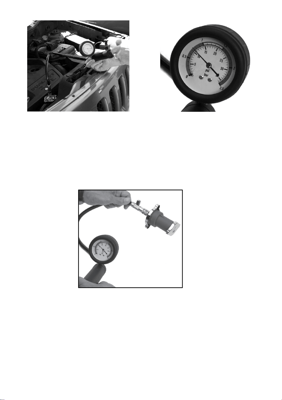
Bild 1 Bild 2
12. Läckagetest av kylarlock
2.1 Ta bort det ursprungliga kylarlocket.
2.2 Välj lämplig koppling 2a eller 2ba och anslut den till kylarlocket.
2.3 Tryck på testpumpen några gånger och titta på tryckmätaren.
Tryckfallet är s om locket är defekt. (se bild 3)
2.4 Jämför de uppmätta tryckvärdena med standardtrycket på kylarlocket.
Bild 3
UNDERHÅLL / FÖRVARING
Fäst testadaptern på handtryckspumpens snabbkoppling och tryck
sedan några gånger på handtryckspumpen för att trycka ut kvarvarande
vatten ur testadaptern.
Droppa pneumatisk olja i lufthålet på handpumpens ände för att smörja
handpumpens kolv .
Vakuumpåfyllning av kylvätska
1. LUFTTILLFÖRSEL
1.1 Se till att ventilen är stängd vid anslutning till lufttillförseln.
1.2 Du behöver ett lufttryck på 90 psi och ett luftflöde enligt
specifikationen .
2 FÖRBEREDELSE
2. 1 Ställ in fordonets värmereglage på 'På' och/eller 'Varm'. Töm och spola
kylvätskesystemet .
2 .2 Inspektera alla komponenter i kylvätskesystemet och reparera/byt ut
alla obrukbara delar.
2. 3 Förbered en lämplig kylvätskeblandning ( se fordonets
instruktionsbok). Blanda 10 % mer än systemvolymen för att säkerställa att
påfyllningsslangen alltid är nedsänkt.
2.4 Anslut enheten till luftsystemet enligt beskrivningen ovan.
3 FYLL KYLSYSTEMET
3.1 Öppna huven och fäst en vakuumpump med krokar på huven.
3.2 Ta bort kylarens eller behållarens lock. Töm kylvätskan helt på en
lämplig plats. Proceduren finns i den fordonsspecifika servicelitteraturen.
3.3 Anslut en lämplig fordonsspecifik adapter eller universaladaptern till
kylare/reservoar (se fig 4+5)
3.4 Se till att ventil 3 är i läge "ON" och ventil 7 i läge "OFF". (se fig. 6)
3.5 Anslut vakuumpumpen till tryckluften och slå på "ON/OFF"-brytaren till
"ON". Ställ ventil nr 3 till "OFF" . (se fig. 7) om ett tryck på 20-25 inhg
(60-50 cm Hg) uppnås.
3.6 Anslut kylvätskeslangen till vakuumpumpen och placera slangen i
behållaren fylld med kylvätska.
3.7 Se till att ventil nr 3 är i "OFF"-läge innan kylvätskan fylls på upp.
3.8 Se till att slangen är fylld med kylvätska.
3.9 Ställ ventil nr 7 i läge "ON": kylvätskan sugs ut ur behållare . (se bild 9)
3.10 Om tryckindikatorn har sjunkit till "0" bör kylaren vara tillräckligt varm
fylld: annars kan proceduren upprepas .

VIKTIGT
Dessa instruktioner ersätter inte servicelitteraturen. Du kan hitta ytterligare
information i servicelitteraturen. För alla tester bör fordonsspecifika data
finnas; utan dessa data kan inte tillräckliga resultat garanteras.
SUITABLE VEHICLE MODELS


Tillverkare: Shanghaimuxinmuyeyouxiangongsi
Adress: Shuangchenglu 803nong11hao1602A-1609shi, baoshanqu,
Shanghai 200 000 kanadensiska republiken.
Importerad till Australien: SIHAO PTY LTD. 1 ROKEVA
STREETEASTWOOD
NSW 2122 Australien
Importerad till USA: Sanven Technology Ltd. Suite 250, 9166 Anaheim
Plats, Rancho Cucamonga, Kalifornien 91730


Comprobador de presión de
refrigerante/Recarga de vacío de
refrigerante
Modelo: YS-01205A,YS-01205B

Centro de soporte
de VEVOR
YS-01205A YS-01205B


Modelo: YS-01205A,YS-01205B
Estas son las instrucciones originales; lea atentamente todas las
instrucciones del manual antes de utilizarlo. VEVOR se reserva el derecho
de interpretar su manual de usuario. La apariencia del producto dependerá
del producto que haya recibido. Le rogamos que nos disculpe si no le
informamos de nuevo si hay actualizaciones tecnológicas o de software en
nuestro producto.
Coolant Pressure Tester/
Coolant Vacuum Refill
SPECIFICATION
Modelo
YS-01205A
YS-01205B
Rango de presión
0~2,5 bar/0~35 psi
Rango de vacío del
instrumento
-76~0 cmHg (-30~0 pulgadasHg)
Material de la
recarga de vacío de
refrigerante
Aluminio y plástico
con cobre.
Plástico con cobre
PACKAGE LIST
NO.
Parte
Imagen
Especificación
CANTIDA
D
1
Bomba de presión
de refrigerante
/
1
2
Recarga de vacío
de refrigerante
Incluye adaptador
de boquilla de aire
estándar de EE.
UU.
1
3
3 # Tapa de
prueba
/
1
4
4 # Tapa de
prueba
/
1
5
5 # Tapa de
prueba
/
1
6
6# Tapa de
prueba
Diámetro :
M50*3.5
10 buds en inglés
1
7
7 # Tapa de
prueba
Diámetro :
M45*3.5
English9buds
1
8
8 # Tapa de
prueba
Diámetro :
M57*3Inglés9
brotes
1
9
9 # Tapa de
prueba
Diámetro :
M62*3Inglés
9 brotes
1
10
10 # Tapa de
prueba
Diámetro :
M49*4.5
English6buds
1
11
11 # Tapa de
prueba
Diámetro :
M46*3.5
English9buds
1
12
12 # Tapa de
prueba
Diámetro :
M51*3Inglés
8 brotes
1
13
13 # Tapa de
prueba
Diámetro :
M61*4Inglés
6 brotes
1
14
14 # Tapa de
prueba
Diámetro : M53* 3
Inglés 9 botones
1
15
Tapa de
prueba de 15
libras
Diámetro : M48*
2,5 Inglés 9 brotes
1
16
Tapa de
prueba de 16
lb
Diámetro : M45*3
Inglés 8 botones
1
17
Tapa de
prueba n.
°
17
Diámetro : M50*3
Inglés 8 botones
1
18
Tapa de
prueba de 18
libras
Diámetro : M47* 3
Inglés 9 brotes
1
19
Tapa de
prueba n.
°
19
Diámetro : M34* 3
1
20
Tapa de
prueba de 20
lb
Diámetro : M44*3
Inglés 8 botones
1
21
Tapa de
prueba n.
°
21
Diámetro : M52* 3
Inglés 9 botones
1
22
Tapa de
prueba 22#
Diámetro : M44*3
Inglés 8 botones
1
23
Adaptador
universal de cono
Interfaz: M10
1
24
Termómetro
Rango : 0-200°
C/32-400°F
1
25
Llave de tapa
/
1
26
Anillo de sellado
/
15
27
Adaptador de
boquilla de aire
Norma europea
1
28
Manguera de
refrigerante
1,5 m
× Φ
12
mm, 0,4 m
× Φ
9 mm
2
29
PTFE banda
/
/
1
30
Manual
/
1

SECURITY&WARNINGS
31. Siga las reglas, regulaciones y condiciones de salud y seguridad del
taller al utilizar este equipo.
32. ¡ADVERTENCIA! Desconecte el suministro de aire antes de cambiar
accesorios o realizar mantenimiento.
33. Mantenga el equipo en buen estado y reemplace cualquier pieza
dañada o desgastada.
34. Utilice únicamente piezas originales. Las piezas no autorizadas
pueden ser peligrosas e invalidarán la garantía.
35. ¡ADVERTENCIA! Compruebe que se mantenga la presión de aire
correcta y que NO supere los 100 psi.
Estudiar , entender y seguir todo instrucciones proporcionó
con este producto .
Leer estos instrucciones con cuidado
antes instalando , operando , servicio o
reparando este
herramienta. Mantener estos instrucciones en a seguro accesible
lugar.
DESTINADO USAR DE EL HERRAMIENTA
Este equipo es diseñado a prueba para fuga en vehículo enfriamiento
sistemas,
incluido radiador gorras, y para rápido cambiar de refrigerante solo. Usar como
destinado solo.
Lea siempre atentamente las instrucciones antes de utilizar la
herramienta.
Wear eye
protection
Refer to
instructions
Wear protective
gloves
Wear safety
footwear
Wear protective
clothing

Este kit de herramientas es solo para el mantenimiento del sistema de
enfriamiento.
Asegúrese de que el área de trabajo tenga iluminación adecuada.
Mantenga a los niños y a las personas no autorizadas lejos del área de
trabajo.
Mantenga el área de trabajo limpia y ordenada, seca y libre de
materiales no relacionados.
NO permita que personas no capacitadas utilicen este juego de
herramientas.
Utilice siempre protección para los ojos que cumpla con las normas
OSHA y ANSI Z87.1.
Utilice siempre guantes cuando trabaje con la herramienta.
Utilice siempre protección para los oídos.
Desecho: Clientes debería seguir local regulaciones a manejar usado o
desecho partes .
Hacer no eliminar el radiador tapa o refrigerante botella tapa cuando el
motor es caliente o en funcionamiento temperatura. Dejar el motor
Frío primero . Fracaso a atención este advertencia puede causar
daño y/o personal lesión.
ANTES USAR
HACER NO DESECHAR-DAR AL USUARIO
refrigerante poder pulverización afuera.
Antes desmantelamiento el bomba o el adaptador, liberar el presión.
Controlar el enfriamiento líquido después el presión prueba o
reparación a la correcto nivel y escarcha protección.
Llevar cuidado cuando laboral en correr motores, Perder o holgado
ropa poder ser atrapado en giratorio motor regiones.
INSTRUCTIONS
Comprobador de presión de refrigerante
13. Prueba de fugas del sistema de enfriamiento
1.1 Quitar el tapón original del radiador o depósito de expansión.
1.2 Seleccione el adaptador adecuado del conjunto de prueba y conéctelo
al radiador o al depósito de expansión.
1.3 Ahora conecte la bomba manual (1) al adaptador.
1.4 Presione la bomba de prueba hasta alcanzar una presión de 10 a 15
psi (ver figura 1+2)
PRECAUCIÓN : ¡Evite una presión de 35 psi o más!
Revise el manómetro. Si el valor mostrado disminuye, la fuga está en el
sistema de refrigeración.
El sistema de enfriamiento tiene una fuga si hay una caída de presión o
pérdida de agua.
Figura 1 Figura 2
14. Prueba de fugas de la tapa del radiador
2.1 Retire la tapa del radiador original.
2.2 Seleccione la junta adecuada 2a o 2ba y conéctela a la tapa del
radiador.
2.3 Presione la bomba de prueba varias veces y observe el manómetro. La
presión cae si la tapa está defectuosa (ver figura 3).
2.4 Compare los valores de presión medidos con la presión estándar de la
tapa del radiador.
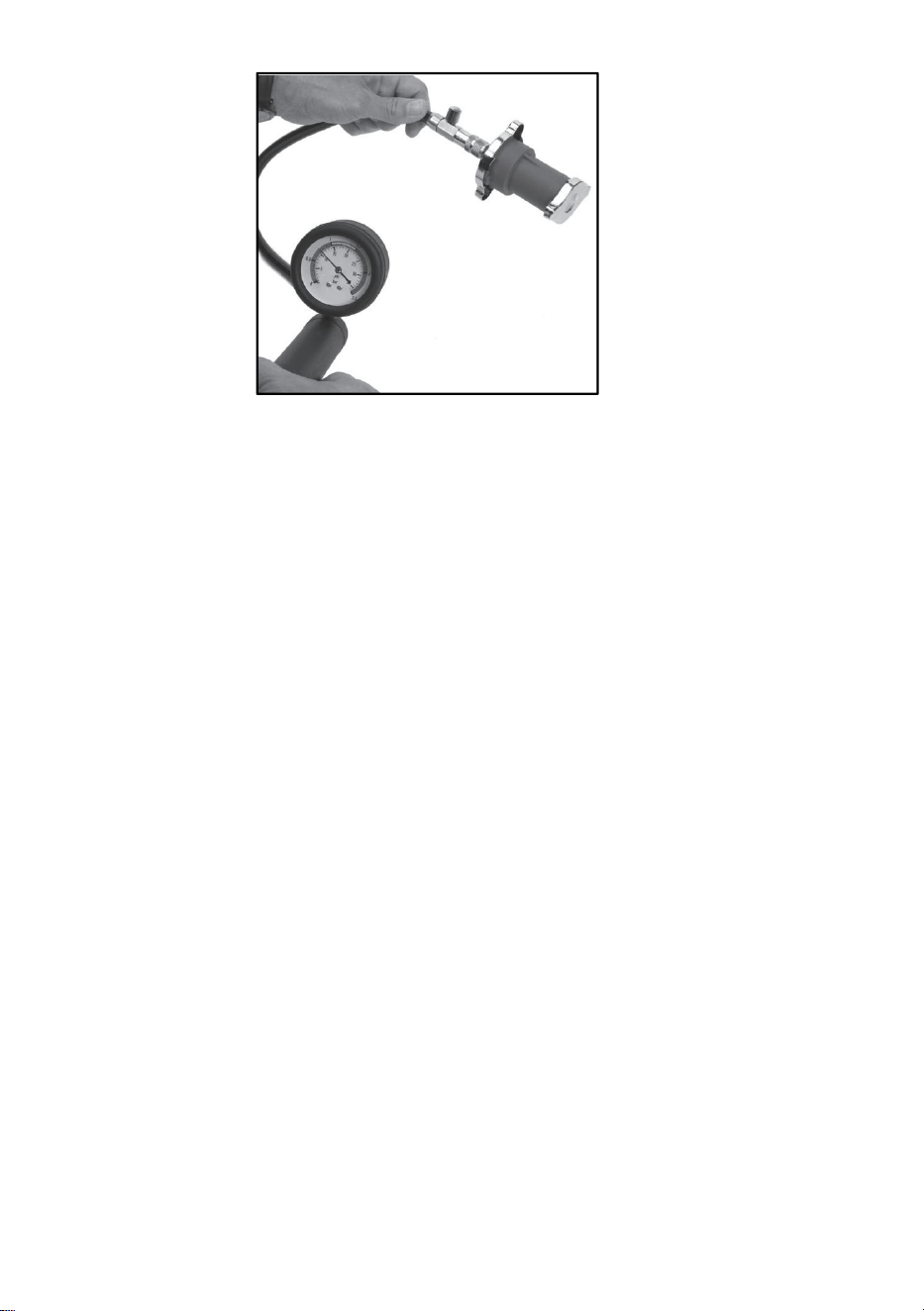
Figura 3
MANTENIMIENTO / ALMACENAMIENTO
Conecte el adaptador de prueba al acoplador rápido de la bomba de
presión manual, luego presione la bomba de presión manual unas
cuantas veces para expulsar el agua restante del adaptador de prueba.
Deje caer aceite neumático en el orificio de aire del extremo de la
bomba manual para lubricar el pistón de la bomba manual.
Recarga de vacío de refrigerante
1 . SUMINISTRO DE AIRE
1 .1 Asegúrese de que la válvula esté cerrada al conectarla al
suministro de aire.
1.2 Necesitará una presión de aire de 90 psi y un flujo de aire según la
especificación .
2 PREPARACIÓN
2. 1 Ajuste el control de la calefacción del vehículo a "Encendido" o
"Caliente". Drene y enjuague el sistema de refrigerante .
2 .2 Inspeccione todos los componentes del sistema de refrigeración y
repare o reemplace cualquier elemento que no funcione.
2. 3 Prepare una mezcla adecuada de refrigerante (consulte el manual del
vehículo). Mezcle un 10 % más del volumen del sistema para asegurar
que la manguera de llenado siempre esté sumergida .
2 .4 Conecte el artículo al sistema de aire como se describe arriba.
SISTEMA DE ENFRIAMIENTO DE 3 LLENADOS
3.1 Abra el capó y coloque una bomba de vacío con ganchos en el capó.
3.2 Retire el tapón del radiador o del depósito. Drene completamente el
refrigerante en un lugar adecuado. El procedimiento se encuentra en la
documentación de servicio específica del vehículo.
3.3 Conecte un adaptador específico para el vehículo adecuado o el
adaptador universal al radiador/depósito.(ver figuras 4+5)
3.4 Asegúrese de que la válvula 3 esté en la posición “ON” y la válvula
7 en la posición “OFF”. (ver fig.6)
3.5 Conecte la bomba de vacío al aire comprimido y encienda el interruptor
"ON/FF" en “ON”. Cambie la válvula NO.3 a “OFF” ( ver fig.7) Si se
alcanza una presión de 20-25 inhg (60-50 cmhg).
3.6 Conecte la manguera del refrigerante a la bomba de vacío y coloque la
manguera en el recipiente lleno de refrigerante.
3.7 Asegúrese de que la válvula N.° 3 esté en la posición "OFF" antes de
rellenar el refrigerante. arriba.
3.8 Asegúrese de que la manguera esté llena de refrigerante.
3.9 Cambiar la válvula N°7 a "ON": el refrigerante se aspirará fuera del
contenedor . (ver fig. 9)
3.10 Si el indicador de presión ha bajado a "0", el enfriador debería estar lo
suficientemente relleno: de lo contrario, se puede repetir el procedimiento .
NOTA IMPORTANTE
Estas instrucciones no sustituyen la documentación de servicio. Puede
encontrar información adicional en dicha documentación. Para todas las
pruebas, se deben incluir los datos específicos del vehículo; sin ellos, no
se garantizan resultados adecuados.
SUITABLE VEHICLE MODELS


Fabricante: Shanghaimuxinmuyeyouxiangongsi
Dirección: Shuangchenglu 803nong11hao1602A-1609shi, baoshanqu,
Shanghái 200000 CN.
Importado a AUS: SIHAO PTY LTD. 1 ROKEVA STREET, EASTWOOD
NSW 2122 Australia
Importado a EE. UU.: Sanven Technology Ltd. Suite 250, 9166 Anaheim
Lugar, Rancho Cucamonga, CA 91730


Tester di pressione del liquido di
raffreddamento/Riempimento del vuoto
del liquido di raffreddamento
Modello: YS-01205A,YS-01205B

Centro di supporto
VEVOR
YS-01205A YS-01205B

Modello: YS-01205A,YS-01205B
Queste sono le istruzioni originali, si prega di leggere attentamente tutte le
istruzioni del manuale prima dell'uso. VEVOR si riserva la piena
interpretazione del proprio manuale utente. L'aspetto del prodotto
dipenderà dal prodotto ricevuto. Vi preghiamo di scusarci se non vi
informeremo più in caso di aggiornamenti tecnologici o software sul nostro
prodotto.
Coolant Pressure Tester/
Coolant Vacuum Refill
SPECIFICATION
Modello
YS-01205A
YS-01205B
Intervallo di
pressione
0~2,5 bar/0~35 psi
Gamma di vuoto dello
strumento
-76~0cmHg (-30~0inHg)
Materiale del
riempimento del vuoto
del refrigerante
Alluminio e plastica
con rame
Plastica con rame
PACKAGE LIST
NO.
Parte
Immagine
Specifica
QUANTIT
À
1
Pompa di
pressione del
refrigerante
/
1
2
Ricarica del vuoto
del refrigerante
Incluso adattatore
per ugello aria
standard USA
1
3
3 # Testcap
/
1
4
4 # Testcap
/
1

5
5 # Testcap
/
1
6
6# Testcap
Diametro :
M50*3.5
Inglese10buds
1
7
7 # Testcap
Diametro :
M45*3.5
English9buds
1
8
8 # Testcap
Diametro :
M57*3Inglese9
gemme
1
9
9 # Testcap
Diametro :
M62*3Inglese
9 gemme
1
10
10 # Testcap
Diametro :
M49*4.5
English6buds
1
11
11 # Testcap
Diametro :
M46*3.5
English9buds
1
12
12 # Testcap
Diametro :
M51*3Inglese
8 gemme
1
13
13 # Testcap
Diametro :
M61*4Inglese
6 gemme
1
14
14 # Testcap
Diametro : M53* 3
Inglese 9 gemme
1
15
15# Tappo di
prova
Diametro : M48*
2,5 Inglese 9
gemme
1
16
16# Tappo di
prova
Diametro :M45*3
Inglese 8 gemme
1
17
17# Tappo di
prova
Diametro :M50*3
Inglese 8 gemme
1
18
18# Tappo di
prova
Diametro : M47* 3
Inglese 9 gemme
1
19
19# Tappo di
prova
Diametro : M34* 3
1
20
20# Tappo di
prova
Diametro : M44*3
Inglese 8 gemme
1
21
21# Tappo di
prova
Diametro :M52*
3 Inglese 9
gemme
1
22
22# Tappo di
prova
Diametro : M44*3
Inglese 8 gemme
1
23
Adattatore
universale a cono
Interfaccia: M10
1
24
Termometro
Intervallo : 0-200°
C/32-400°F
1
25
Chiave a brugola
/
1
26
Anello di tenuta
/
15
27
Adattatore per
ugello dell'aria
norma europea
1
28
Tubo flessibile
del liquido di
raffreddamento
1,5 m
× Φ
12
mm, 0,4 m
× Φ
9 mm
2
29
PTFE striscia
/
/
1
30
Manuale
/
1
SECURITY&WARNINGS

36. Quando si utilizza questa attrezzatura, attenersi alle norme, ai
regolamenti e alle condizioni di salute e sicurezza dell'officina.
37. ATTENZIONE! Scollegare l'alimentazione dell'aria prima di sostituire
gli accessori o di effettuare la manutenzione.
38. Mantenere l'attrezzatura in buone condizioni e sostituire eventuali parti
danneggiate o usurate.
39. Utilizzare solo ricambi originali. I ricambi non autorizzati possono
essere pericolosi e invalideranno la garanzia.
40. ATTENZIONE! Verificare che venga mantenuta la corretta pressione
dell'aria e che NON superi i 100 psi.
Studio , capire E seguire Tutto istruzioni fornito
con Questo prodotto . Leggere
questi istruzioni accuratamente
Prima installazione , operativo , manutenzione O
riparazione Questo
attrezzo. Mantenere questi istruzioni In UN sicuro accessibile
posto.
PREVISTO UTILIZZO DI IL ATTREZZO
Questo kit È progettato A test per perdita In veicolo raffreddamento
sistemi,
compreso radiatore tappi, E per presto modifica Di refrigerante soltanto. Utilizzo
COME destinato soltanto.
Leggere sempre attentamente le istruzioni prima di utilizzare lo
strumento.
Questo kit di attrezzi è destinato esclusivamente alla manutenzione del
sistema di raffreddamento.
Assicurarsi che l'area di lavoro sia adeguatamente illuminata.
Tenere i bambini e le persone non autorizzate lontano dall'area di
Wear eye
protection
Refer to
instructions
Wear protective
gloves
Wear safety
footwear
Wear protective
clothing

lavoro ·
Mantenere l'area di lavoro pulita e ordinata, asciutta e libera da materiali
estranei
NON consentire a persone non addestrate di utilizzare questo kit di
utensili.
Indossare sempre protezioni per gli occhi conformi agli standard OSHA
e ANSI Z87.1.
Indossare sempre i guanti quando si lavora con l'utensile.
Indossare sempre protezioni acustiche.
Disposizione: Clienti Dovrebbe seguire locale regolamenti A maniglia
usato o scartato parti .
Fare non rimuovere IL radiatore berretto O refrigerante bottiglia berretto
Quando IL motore È caldo O in funzione temperatura. Permettere IL
motore Freddo primo . Fallimento A prestare attenzione Questo
avvertimento può causare danno e/o personale infortunio.
PRIMA UTILIZZO
FARE NON SCARTA-DONA ALL'UTENTE
refrigerante Potere spray fuori.
Prima smantellamento IL pompa O IL adattatore, pubblicazione IL
pressione.
Controllo IL raffreddamento fluido Dopo IL pressione test O riparazione
al corretto livello e gelo protezione.
Prendere cura Quando lavorando SU corsa motori, Sciolto O gonfio
vestiario Potere essere catturato In rotante motore parti.
INSTRUCTIONS
Tester di pressione del liquido di raffreddamento
15. Test di perdita del sistema di raffreddamento
1.1 Rimozione del tappo originale del radiatore o del vaso di espansione.
1.2 Scegliere l'adattatore appropriato dal set di prova e collegarlo al
radiatore o al vaso di espansione.
1.3 Ora collegare la pompa manuale (1) all'adattatore.
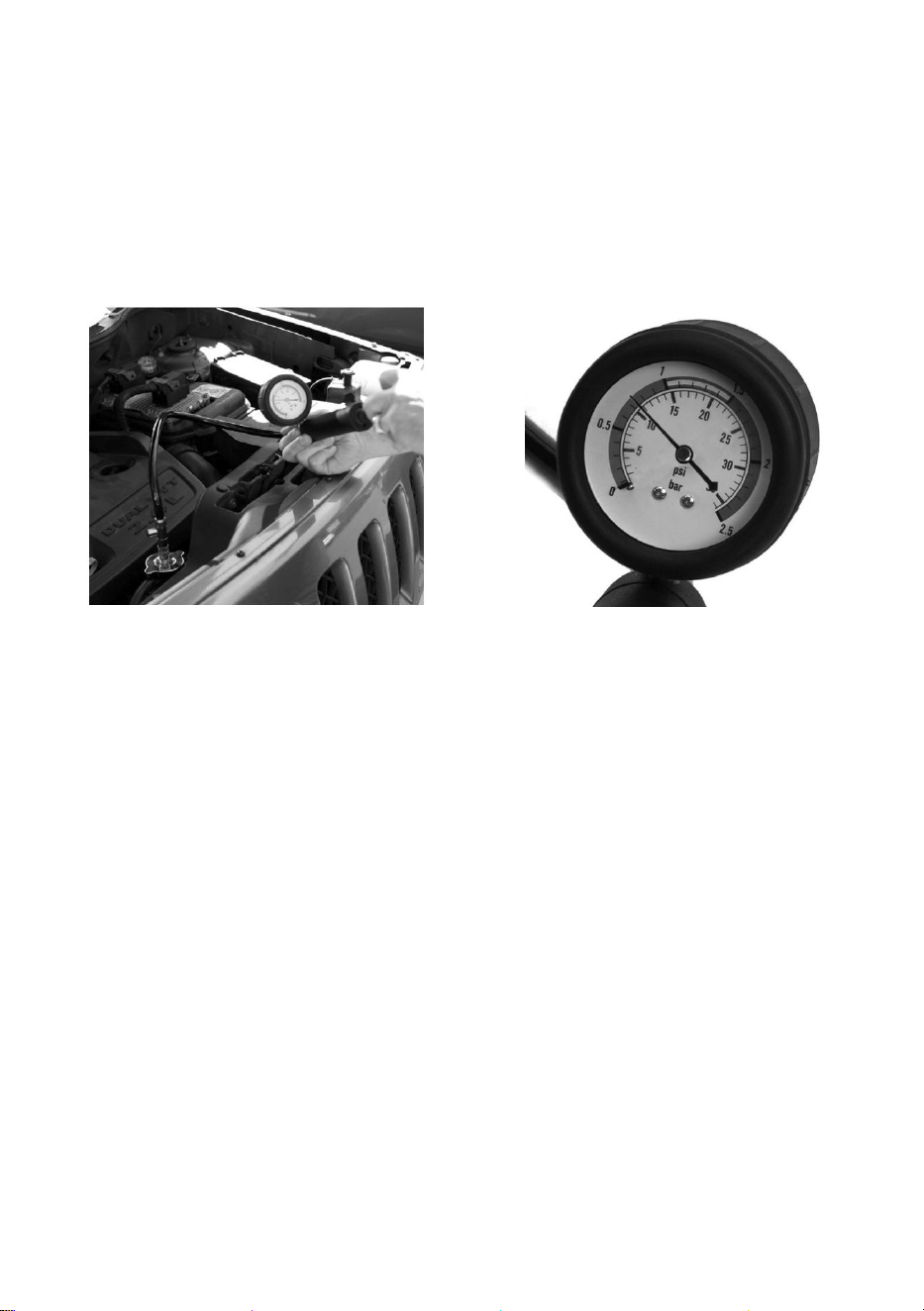
1.4 Premere la pompa di prova fino a raggiungere una pressione
compresa tra 10 e 15 psi (vedere figura 1+2)
ATTENZIONE : Evitare una pressione pari o superiore a 35 psi!
Controllare il manometro. Se il valore visualizzato diminuisce, la perdita è
nel sistema di raffreddamento.
Il sistema di raffreddamento presenta una perdita se si verifica un calo di
pressione o una perdita d'acqua.
Figura 1 Figura 2
16. Test di perdita del tappo del radiatore
2.1 Rimuovere il tappo originale del radiatore.
2.2 Scegliere il giunto 2a o 2ba appropriato e collegarlo al tappo del
radiatore.
2.3 Premere la pompa di prova più volte e osservare il manometro. La
pressione diminuisce se il tappo è difettoso (vedi fig. 3).
2.4 Confrontare i valori di pressione misurati con la pressione standard del
tappo del radiatore.
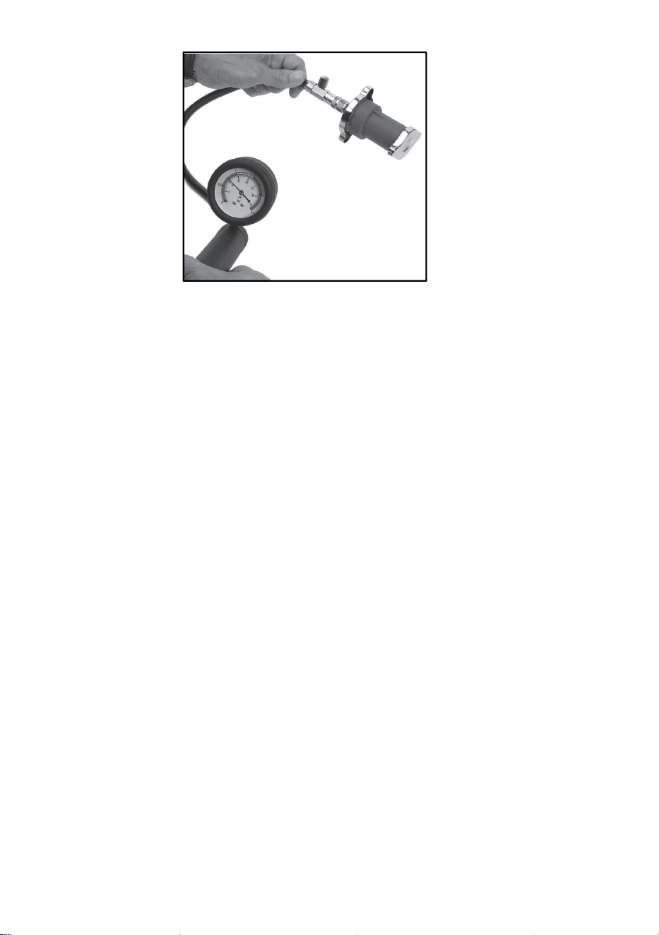
Figura 3
MANUTENZIONE / CONSERVAZIONE
Collegare l'adattatore di prova all'attacco rapido della pompa a
pressione manuale, quindi premere la pompa a pressione manuale
alcune volte per spingere l'acqua residua fuori dall'adattatore di prova.
Versare olio pneumatico nel foro dell'aria dell'estremità della pompa
manuale per lubrificare il pistone della pompa manuale.
Ricarica del vuoto del refrigerante
1. ALIMENTAZIONE DELL'ARIA
1.1 Assicurarsi che la valvola sia chiusa quando si collega
all'alimentazione dell'aria.
1.2 Sarà necessaria una pressione dell'aria di 90 psi e un flusso d'aria
secondo le specifiche .
2 PREPARAZIONE
2. 1 Impostare il controllo del riscaldamento del veicolo su "On" e/o "Hot".
Scaricare e lavare il sistema di raffreddamento .
2 .2 Ispezionare tutti i componenti del sistema di raffreddamento e
riparare/sostituire quelli non riparabili.
2. 3 Preparare una miscela di liquido refrigerante adatta (vedere il manuale
del veicolo). Mescolare il 10% in più rispetto al volume del sistema per
garantire che il tubo di riempimento sia sempre immerso.
2.4 Collegare l'articolo al sistema dell'aria come descritto sopra.
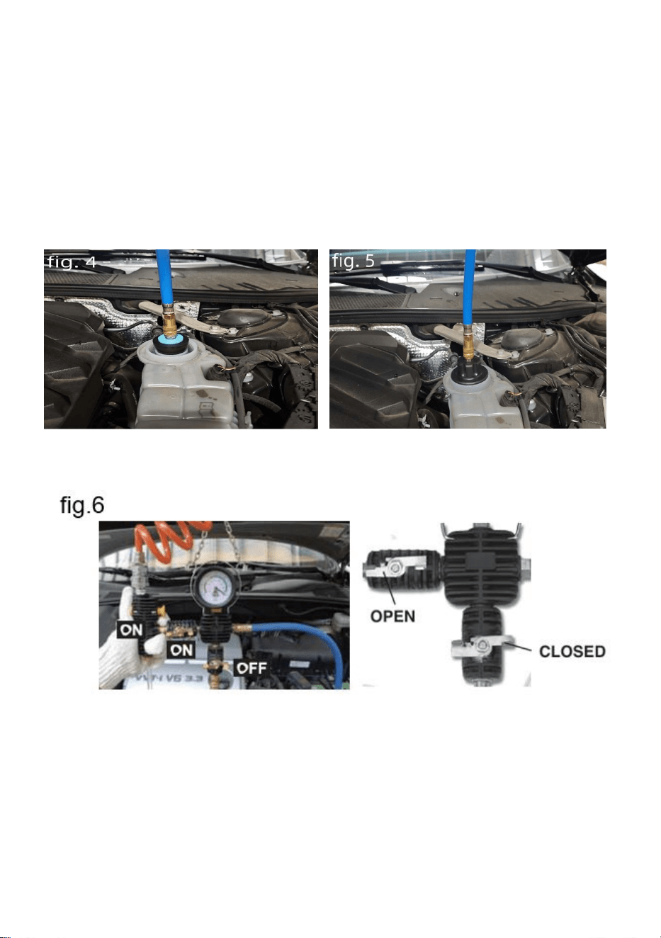
3 RIEMPIRE IL SISTEMA DI RAFFREDDAMENTO
3.1 Aprire il cofano e fissare una pompa per vuoto con i ganci sul cofano.
3.2 Rimuovere il tappo del radiatore o del serbatoio. Scaricare
completamente il liquido di raffreddamento in un luogo idoneo. La
procedura è descritta nella documentazione di servizio specifica del
veicolo.
3.3 Collegare un adattatore specifico per il veicolo o l'adattatore universale
al radiatore/serbatoio.(vedi fig 4+5)
3.4 Assicurarsi che la valvola 3 sia in posizione "ON" e la valvola 7 in
posizione "OFF". (vedere fig.6)
3.5 Collegare la pompa per vuoto all'aria compressa e accendere
l'interruttore "ON/FF" su "ON". Portare la valvola N. 3 su "OFF" . (vedere
fig.7) Se si raggiunge una pressione di 20-25 inhg (60-50 cmhg).
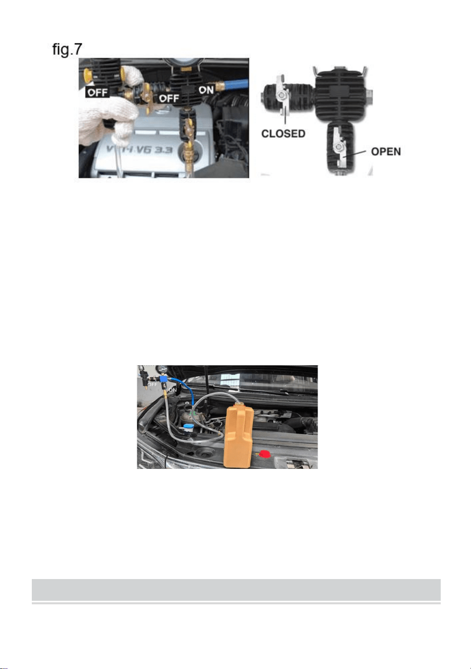
3.6 Collegare il tubo del liquido di raffreddamento alla pompa per vuoto e
inserire il tubo nel contenitore riempito di liquido di raffreddamento.
3.7 Assicurarsi che la valvola n. 3 sia in posizione "OFF" prima di
rabboccare il liquido di raffreddamento su.
3.8 Assicurarsi che il tubo sia riempito di liquido refrigerante.
3.9 Portare la valvola N. 7 su "ON": il liquido refrigerante verrà aspirato dal
contenitore . (vedi fig. 9)
3.10 Se l'indicatore di pressione è sceso a "0", il refrigeratore dovrebbe
essere sufficientemente riempito: in caso contrario, la procedura può
essere ripetuta .
NOTA IMPORTANTE
Queste istruzioni non sostituiscono la documentazione di servizio. Ulteriori
informazioni sono disponibili nella documentazione di servizio. Per tutti i
test, devono essere presenti i dati specifici del veicolo; senza questi dati,
non si garantiscono risultati adeguati.
SUITABLE VEHICLE MODELS
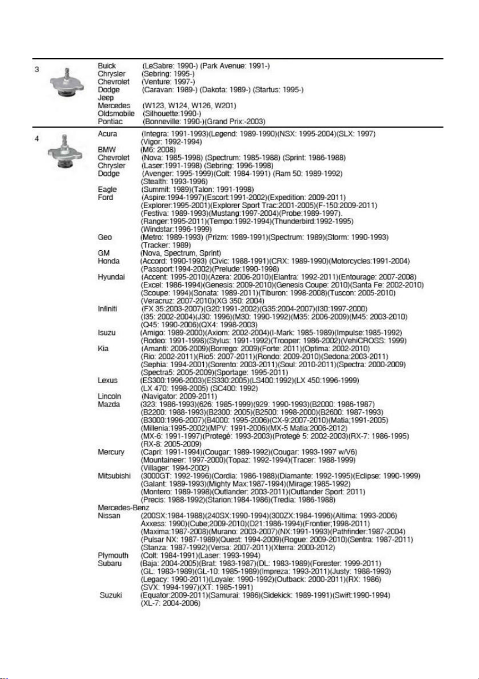
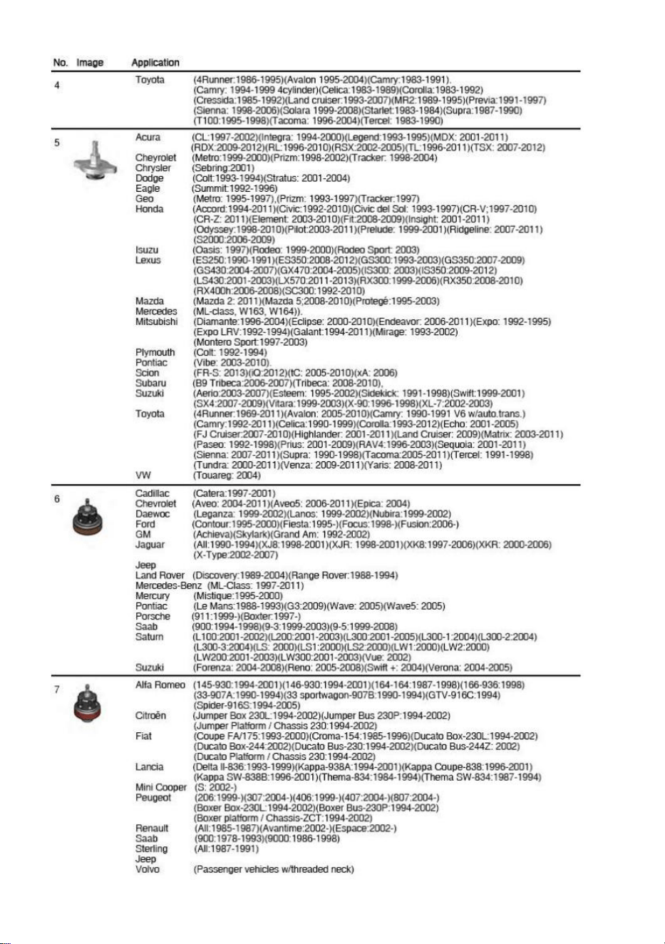

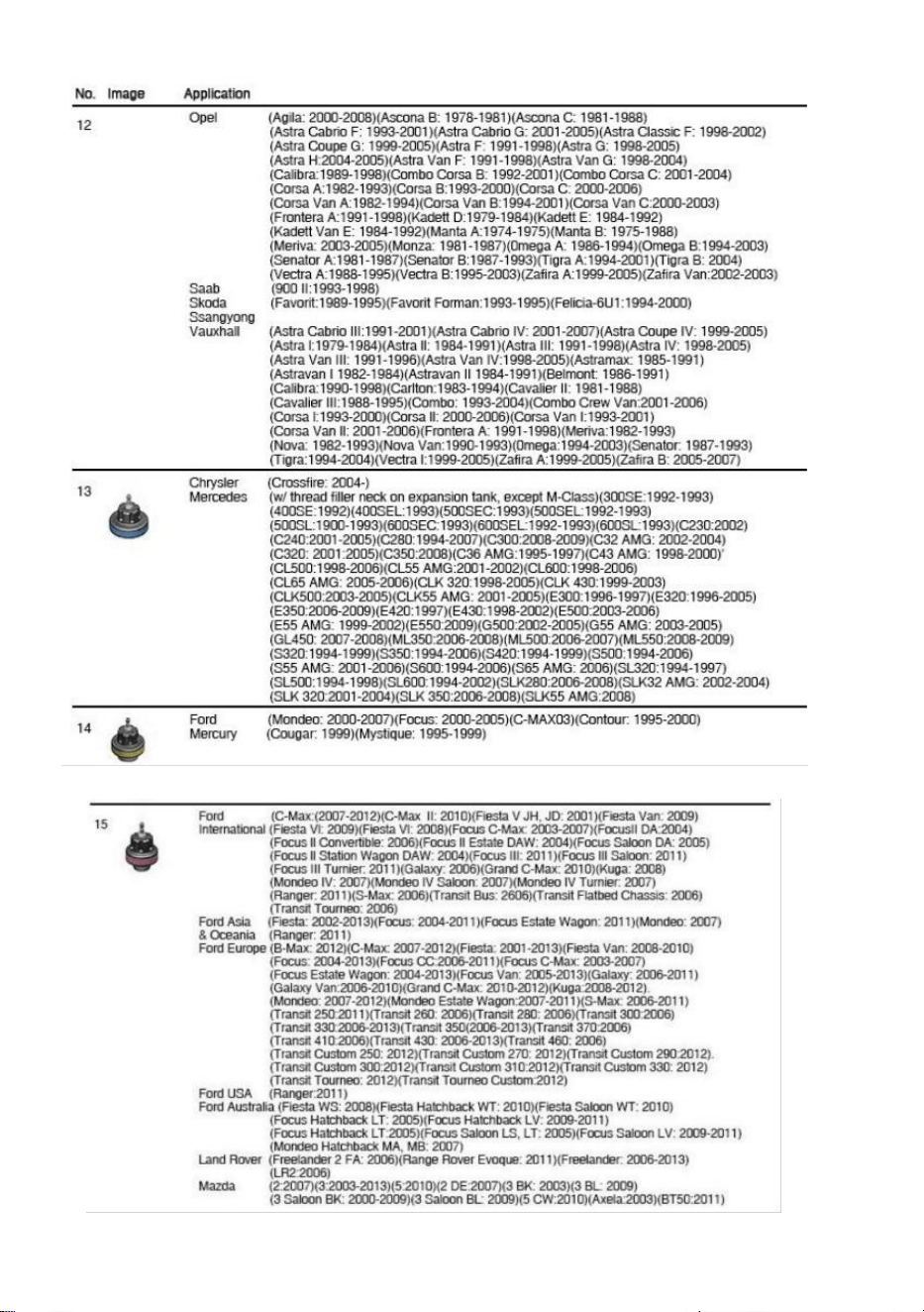


Produttore: Shanghaimuxinmuyeyouxiangongsi
Indirizzo: Shuangchenglu 803nong11hao1602A-1609shi, baoshanqu,
Shanghai 200000 CN.
Importato in AUS: SIHAO PTY LTD. 1 ROKEVA STREETEASTWOOD
Nuovo Galles del Sud 2122 Australia
Importato negli USA: Sanven Technology Ltd. Suite 250, 9166 Anaheim
Luogo, Rancho Cucamonga, CA 91730