Manufactured by:
ECR International Inc.
2201 Dwyer Avenue, Utica, NY 13501
Tel.
800 325 5479
www.ecrinternational.com
PN 240013101 REV. B [08/08/2023]
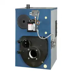
FSB SERIES 3
Gas-Fired Hot Water
Induced Draft Boilers
INSTALLATION, OPERATION &
MAINTENANCE MANUAL
Models
FSB-2
FSB-3
FSB-4
FSB-5
FSB-6
Tested For 50 psi
ASME
Working Pressure
C.S.A. Certied
For Natural Gas Or Propane

2
1 - Physical Data ������������������������������������������������������������������������������������������������������������� 4
2 - Safety Symbols And Warnings ������������������������������������������������������������������������������������ 5
2.1. Safety Symbols & Warnings ......................................................................................5
2.2 For Your Safety ........................................................................................................6
3 - Locating The Boiler ���������������������������������������������������������������������������������������������������� 7
3.1 Installation Requirements ..........................................................................................7
3.2 Boiler Location Considerations ...................................................................................8
4 - Connecting Supply And Return Piping ������������������������������������������������������������������������ 9
4.1 Safety Relief Valve Installation ...................................................................................9
4.2 Supply And Return Requirements ..............................................................................11
5 - Ventilation & Combustion Air ����������������������������������������������������������������������������������� 12
6 - Vent System Modification ����������������������������������������������������������������������������������������� 13
7 - Vent Installation ������������������������������������������������������������������������������������������������������ 14
7.1 Chimney Venting (Category I) ..................................................................................14
7.2 Requirements ........................................................................................................14
8 - Horizontal Venting Instructions ���������������������������������������������������������������������������� 16
9 - Optional Horizontal Venting Instruction��������������������������������������������������������������������21
10 - Gas Supply Piping �������������������������������������������������������������������������������������������������� 22
11 - Electrical Wiring ����������������������������������������������������������������������������������������������������� 24
11.1 Electrical Wiring Requirements ................................................................................24
11.2 Thermostat Installation ..........................................................................................24
12 - Wiring Diagram ������������������������������������������������������������������������������������������������������ 25
13 - Sequence Of Operation ������������������������������������������������������������������������������������������� 26
14 - Starting Your Boiler������������������������������������������������������������������������������������������������ 27
14.1 Filling System.......................................................................................................27
14.2 Operating Instructions ...........................................................................................28
14.3 Turn Off Gas To Appliance ......................................................................................28
15 - Checking And Adjusting ����������������������������������������������������������������������������������������� 29
15.1 Gas Valve Safety Shutdown Test .............................................................................29
15.2 Pilot Burner Adjustment ......................................................................................... 29
15.3 Main Burner(S) Inspection .....................................................................................29
15.4 Adjusting Limit Controls .........................................................................................29
15.5 Thermostat Heat Anticipator Setting ........................................................................30
16 - Maintaining Your Boiler ������������������������������������������������������������������������������������������ 31
17 - Service Hints ���������������������������������������������������������������������������������������������������������� 32
18 - Boiler Ratings & Capacities ������������������������������������������������������������������������������������ 33
Appendix A - Control Module ����������������������������������������������������������������������������������������� 34
A.1 Installation Environment Considerations.....................................................................34
A.2 Electrical Connections .............................................................................................34
A.3 Adjusting Settings ..................................................................................................34
A.5 Display .................................................................................................................36
A.6 Operation ..............................................................................................................38
A.7 Boiler High Limit Temperature Controller.....................................................................38
A.8 Troubleshooting......................................................................................................38
A.9 Intermittent Pilot .................................................................................................... 40
TABLE OF CONTENTS
PN 240013101 Rev. B [08/08/2023]
3
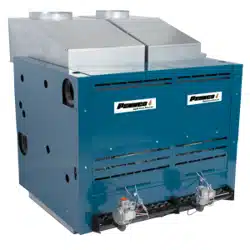
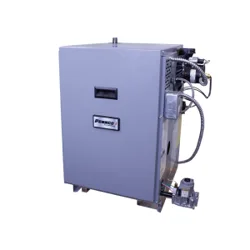
VERIFY CONTENTS RECEIVED
Fully Assembled Boiler *Vent Adapter
*Fuse Link
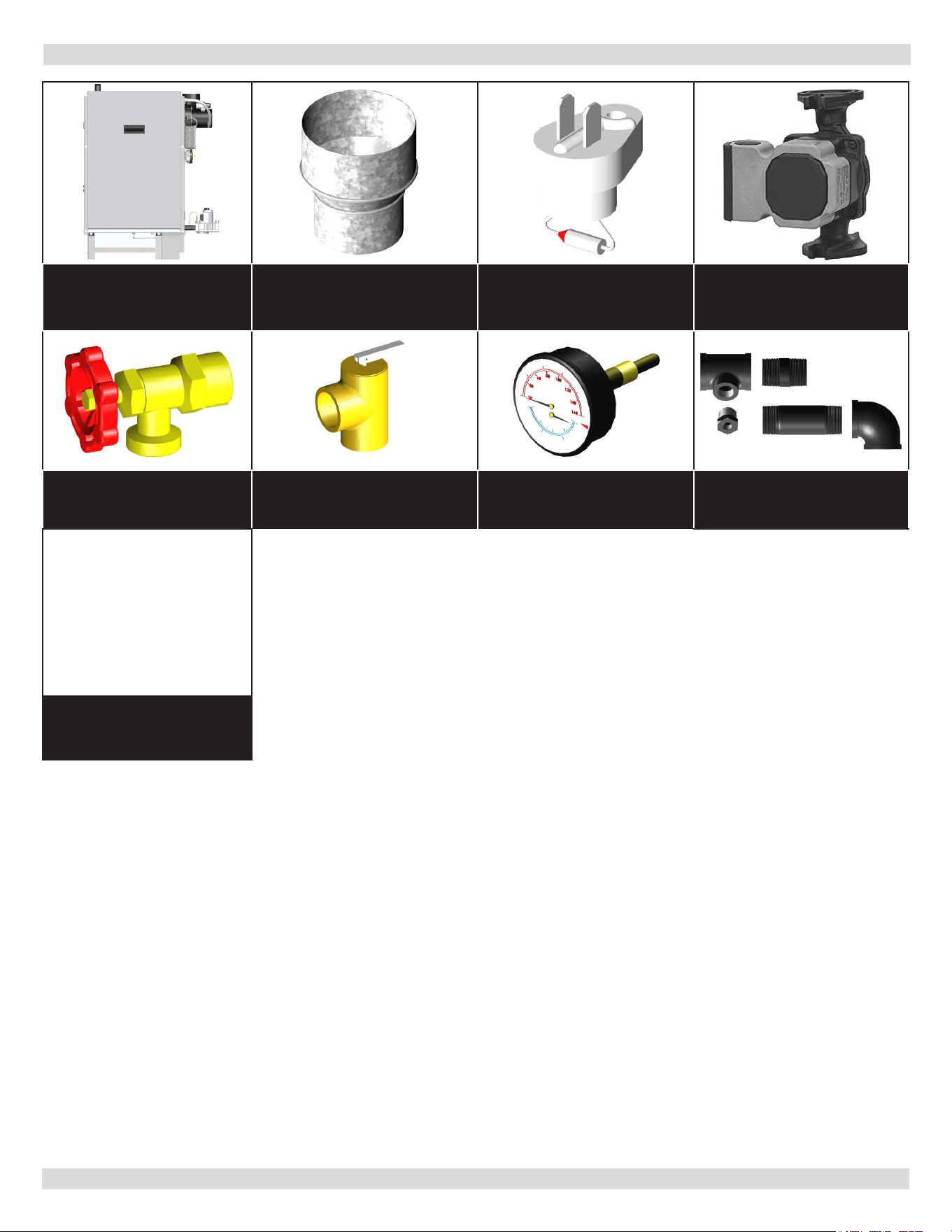
Pump (Optional)
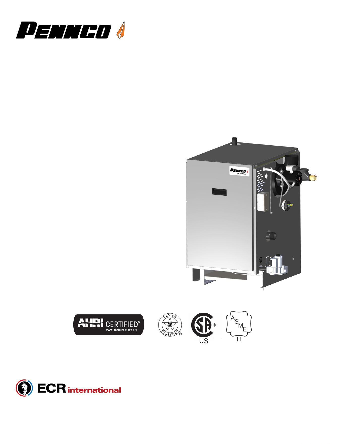
*Drain Valve *ASME Safety Relief Valve *Tridicator
*Black Iron Fittings
(see parts list for sizes
and use)
Includes Essential
Documents and Warranty
11x17 Wire Diagrams
Document Package
KEEP THIS MANUAL NEAR BOILER
RETAIN FOR FUTURE REFERENCE
Information and specications outlined in this manual in eect at the
time of printing of this manual� ECR International eserves the right to
discontinue, change, specications or system design at any time without
notice and without incurring any obligation, whatsoever.
* Items found in parts box included with your boiler.
PN 240013101 Rev. B [08/08/2023]
For Parts list see manual 240013102 included with your boiler literature package.
Check our website frequently for updates: www.ecrinternational.com
4
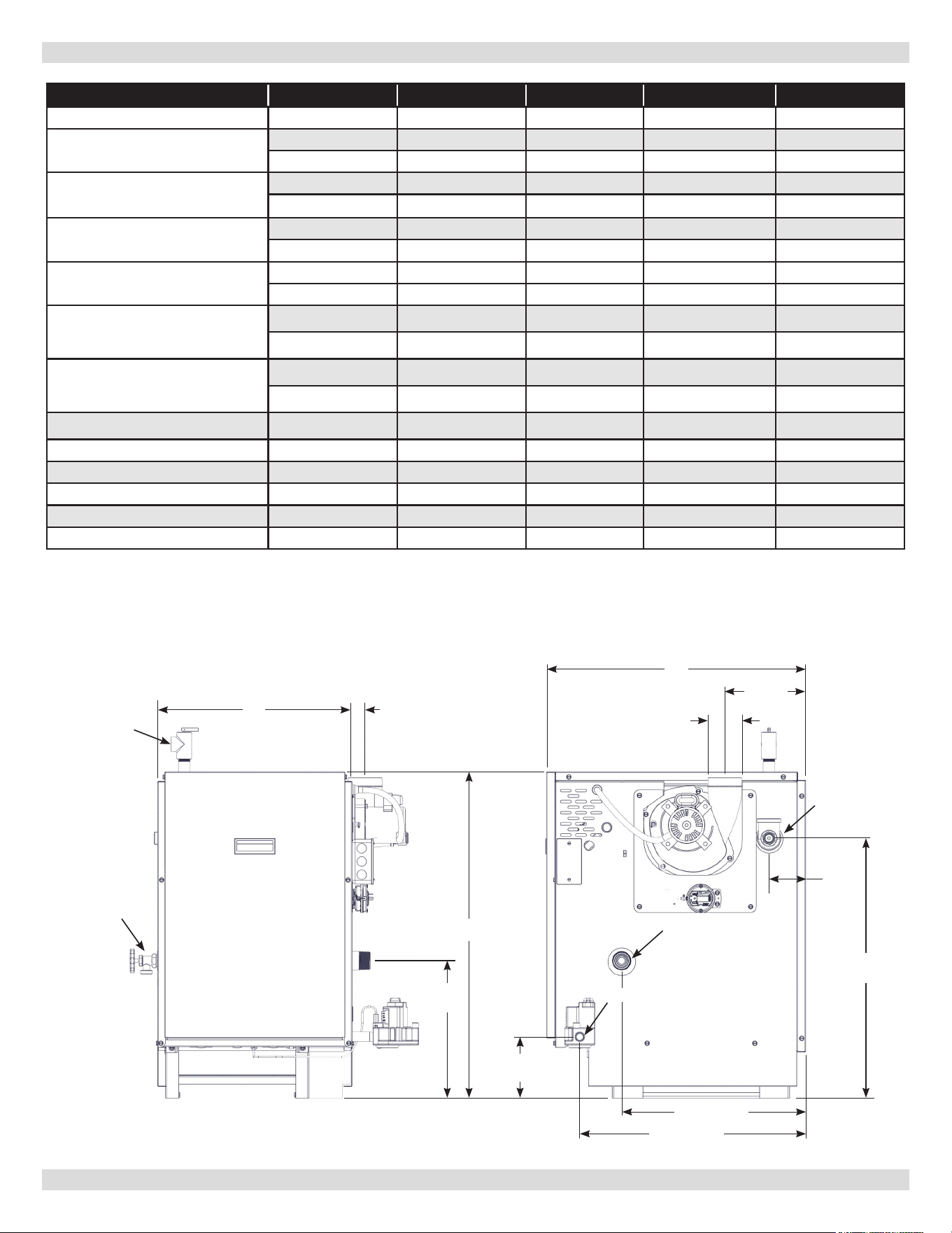
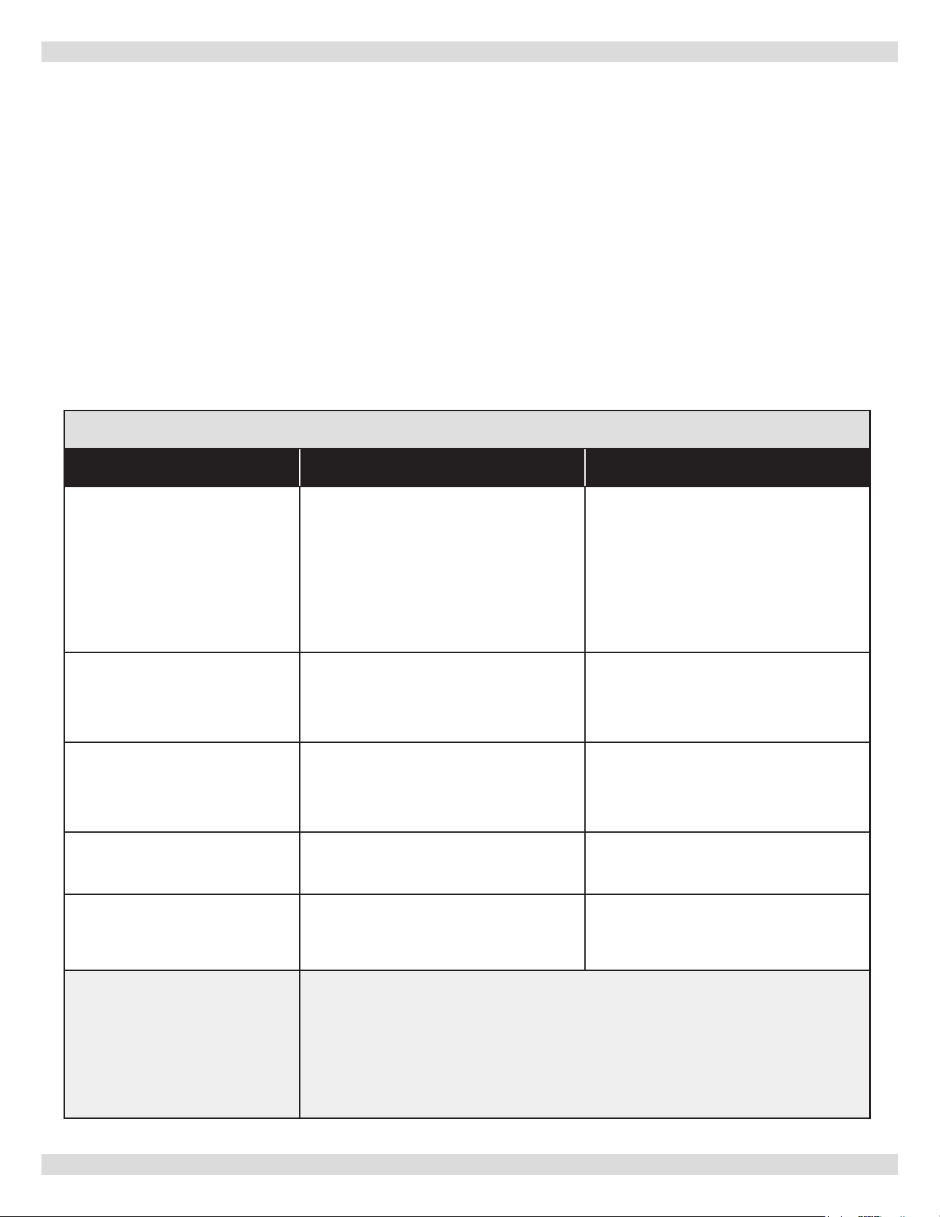
1 - PHYSICAL DATA
Model
FSB-2 FSB-3 FSB-4 FSB-5 FSB-6
# Sections 2 3 4 5 6
A Width
11" 14-¹/4" 17-1/2" 20-3/4" 24"
279 mm 362 mm 445 mm 527 mm 610 mm
B Height
29” 29” 29” 29” 29”
737 mm 737 mm 737 mm 737 mm 737 mm
C Depth
23-1/4" 23-1/4” 23-1/4” 23-1/4” 23-1/4”
591 mm 591 mm 591 mm 591 mm 591 mm
D Vent Location
2-
5/16
" 2-
5/16
” 2-
5/16
” 2-
5/16
” 2-
5/16
”
59 mm 59 mm 59 mm 59 mm 59 mm
E Flue Diameter (Sidewall)
3” 3” 3” 3” 4”
76 mm 76 mm 76 mm 76 mm 102 mm
F Flue Diameter (Chimney)
4" 4" 4" 4" 4"
102 mm 102 mm 102 mm 102 mm 102 mm
Supply & Return Tappings 1-
¹/4
" NPT 1-
¹/4
" NPT 1-
¹/4
" NPT 1-
¹/4
" NPT 1-
¹/4
" NPT
Natural Gas Inlet 1/2" NPT 1/2" NPT 1/2" NPT 1/2" NPT 1/2" NPT
Relief Valve NPT 3/4" NPT 3/4" NPT 3/4" NPT 3/4" NPT 3/4" NPT
Drain Valve NPT 3/4" NPT 3/4" NPT 3/4" NPT 3/4" NPT 3/4" NPT
Heating Water Content, Gal (Liters) 1.75 (6.6) 3 (11.4) 4.25 (16.1) 5.5 (20.9) 6.75(25.6)
Boiler Weight, less pkg - Lbs (KG) 225 (102.1) 265 (120.2) 322 (146.1) 370 (167.8) 431 (195.5)
Front View Right Side View
"A" "D"
"B"
"E/F"
125/16"
(313.1 mm)
235/16"
(592.6 mm)
"C"
GAS SUPPLY
71/4"
(184mm)
31/4"
(83mm)
205/8" (516 mm)
161/2" (419 mm)
51/2"
(117.8mm)
SUPPLY
RETURN
DRAIN VALVE
ASME RELIEF
VALVE
PN 240013101 Rev. B [08/08/2023]
5
2 - SAFETY SYMBOLS AND WARNINGS
CAUTION
Indicates a hazardous situation which, if not
avoided, could result in minor or moderate injury.
!!
WARNING
Indicates a hazardous situation which, if not
avoided, could result in death or serious injury.
!
DANGER
Indicates a hazardous situation which, if not
avoided, WILL result in death or serious injury.
!
This is the safety alert symbol. Symbol alerts
you to potential personal injury hazards. Obey all
safety messages following this symbol to avoid
possible injury or death.
Become familiar with symbols identifying potential hazards.
Boiler installation shall be completed by qualied agency.
WARNING
Do not tamper with or use this boiler for any
purpose other than its intended use. Failure to follow
these instructions could result in death or serious
injury. Use only manufacturer recommended parts
and accessories.
!
CAUTION
Laceration, burn hazard. Metal edges and parts
may have sharp edges and/or may be hot. Use
appropriate personal protection equipment to
include safety glasses and gloves when installing
or servicing this boiler. Failure to follow these
instructions could result in minor or moderate injury.
!!
NOTICE
Used to address practices not related to personal
injury.
WARNING
Fire, explosion, asphyxiation and electrical shock
hazard. Improper installation could result in death
or serious injury. Read this manual and understand
all requirements before beginning installation.
!
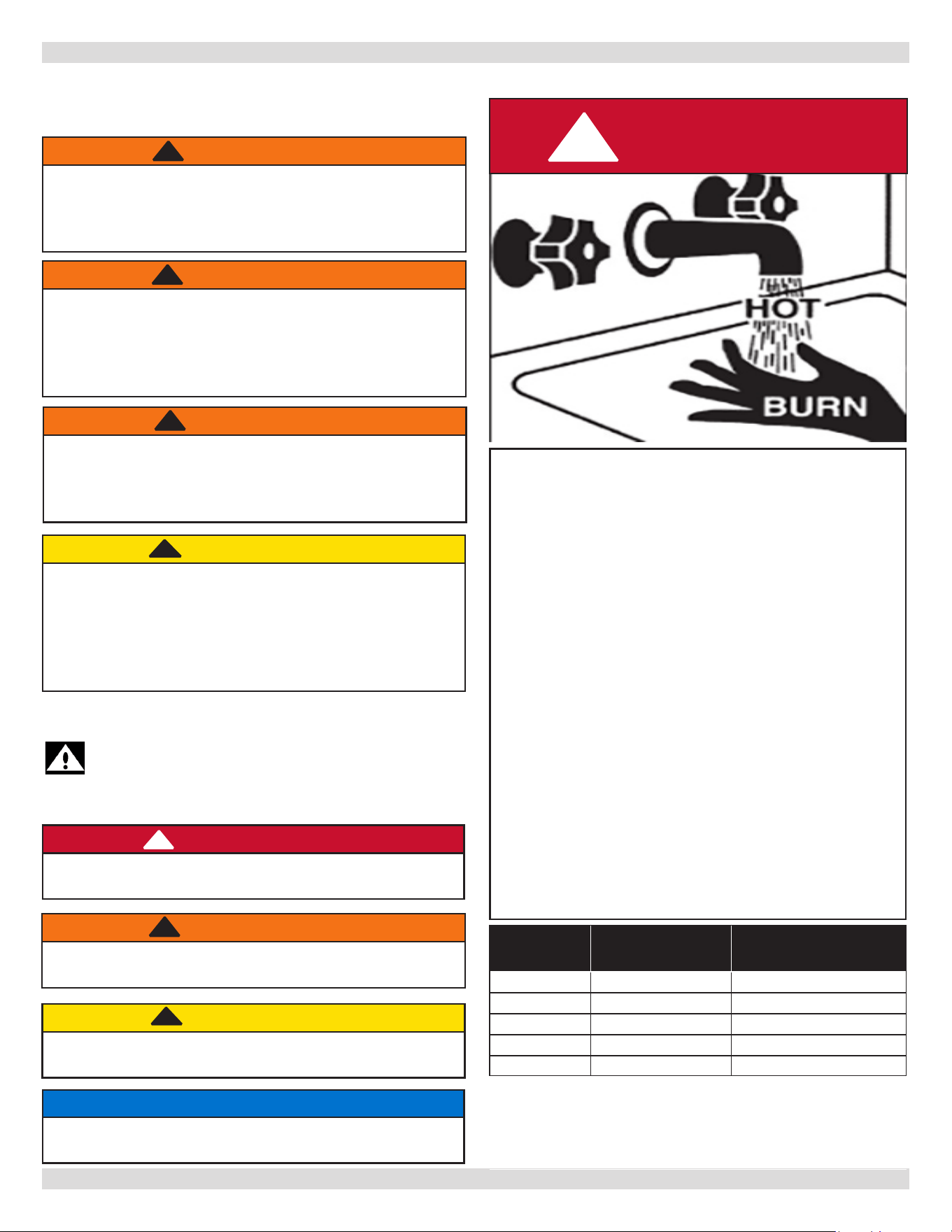
FOR YOUR SAFETY READ BEFORE OPERATING
Hot Water Can Scald!
Water heated to temperature for clothes washing,
dish washing and other sanitizing needs can scald and
cause permanent injury.
Children, elderly, and inrm or physically handicapped
persons are more likely to be permanently injured by
hot water. Never leave them unattended in bathtub or
shower. Never allow small children to use a hot water
tap or draw their own bath.
If anyone using hot water in the building ts the above
description, or if state laws or local codes require
certain water temperatures at hot water taps, you
must take special precautions:
• Use lowest possible temperature setting.
• Install some type of tempering device, such as
an automatic mixing valve, at hot water tap or
water heater. Automatic mixing valve must be
selected and installed according to manufacturer's
recommendations and instructions.
• Water passing out of drain valves may be
extremely hot. To avoid injury:
• Make sure all connections are tight.
• Direct water ow away from any person.
DANGER
!
Water
Temperature
Seng
1st Degree Burn
Exposure Time For
An Adult
2nd and 3rd Degree Burn
Exposure Time For An
Adult
120° F 1 minute 5 minutes
130° F 5 seconds 30 seconds
140° F 2 seconds 5 seconds
150° F 1 second 1.5 seconds
160° F Instantaneous 0.5 seconds
Note: Warning for Infants, Children, and Elderly:
Great care must be taken when exposing the
aforementioned groups to warm or hot water as they
can be badly burned in exposure times less than half
of the time for an adult.
2�1� Safety Symbols & Warnings
WARNING
Adding water to a hot boiler may result in heat
exchanger failure. Before lling boiler verify heat
exchanger is not hot. Failure to follow these
instructions could result in death or serious injury.
!
PN 240013101 Rev. B [08/08/2023]
6
WARNING
Keep boiler area clear and free from combustible
materials, gasoline and other ammable vapors and
liquids.
DO NOT obstruct air openings to the boiler room.
Modication, substitution or elimination of factory
equipped, supplied or specied components may
result in personal injury or loss of life.
Installation and service of this boiler shall be performed
by a qualied installer.
When this product is installed in the Commonwealth
of Massachusetts the installation shall be performed
by a Licensed Plumber or Licensed Gas Fitter.
!
WARNING
Combustion chamber insulation in this product
contains ceramic ber material. Ceramic bers
can be converted to cristobalite in very high
temperature applications. The International Agency
for Research on Cancer (IARC) has concluded,
Crystalline silica inhaled in the form of quartz
or cristobalite from occupational sources is
carcinogenic to humans (Group1). Avoid breathing
dust and contact with skin and eyes. Use NIOSH
certied dust respirator (N95). This type of
respirator is based on the OSHA requirements
for cristobalite at the time this document was
written. Other types of respirators may be needed
depending on the job site conditions. Current
NIOSH recommendations can be found on the
NIOSH website https://www.cdc.gov/niosh/topics/
silica/. NIOSH approved respirators, manufacturers,
and phone numbers are also listed on this website.
Wear long-sleeved, loose tting clothing, gloves,
and eye protection. Apply enough water to the
combustion chamber lining to prevent dust. Wash
potentially contaminated clothes separately from
other clothing. Rinse clothes washer thoroughly.
NIOSH stated First Aid. Eye: Irrigate immediately.
Breathing: Fresh air.
!
2 - SAFETY SYMBOLS AND WARNINGS
Installer shall verify that at least one carbon Installer shall verify that at least one carbon
monoxide alarm has been installed within a monoxide alarm has been installed within a
residential living space or home, following the alarm residential living space or home, following the alarm
manufacturer’s instructions and applicable codes manufacturer’s instructions and applicable codes
before putting the appliance into operation�before putting the appliance into operation�
2�2 For Your Safety
WARNING
Fire, Explosion, Asphyxiation, Electrical shock
hazard! Flooding will result in damages such as
electrical problems, corrosion, inoperative parts,
mold and other unforeseen issues which can
occur over time. Any equipment determined by
a professional as damaged by a ood, dened
as excess of water or other liquid, shall be
replaced. Failure to follow these directions will
result in a Hazardous Situation.
!
WARNING
This prod
uct contains Fibrous glass. Fibrous
glass is a synthetic ber made from tiny particles
of glass. Fibrous glass has been classied as a
possible human carcinogen. When disturbed as a
result of servicing or repair, brous glass becomes
airborne and, if inhaled, may be hazardous to
your health. It can harm the eyes, skin, and the
lungs. Airborne bers from these materials have
been listed by the State of California as a possible
cause of cancer through inhalation. Adhere
to the following precautions and procedures.
Avoid breathing dust and contact with skin and
eyes. Use NIOSH certied dust respirator (e.g.,
N95). Other types of respirators may be needed
depending on the job site conditions. Current NIOSH
recommendations can be found on the NIOSH
website https://www.cdc.gov/niosh/. Approved
respirators, manufacturers, and phone numbers
are also listed on this website. Wear appropriate
personal protective clothing to prevent skin contact,
as well as gloves and eye protection. Wash skin
daily at end of each work shift, and prior to eating,
drinking, smoking, etc. Workers whose clothing
may have been contaminated should change into
uncontaminated clothing before leaving the work
premises. Wash potentially contaminated clothes
separately from other clothing. Rinse clothes washer
thoroughly. Follow all Local, State and Federal
guidelines for disposal.
NIOSH stated First Aid. Eye: Irrigate immediately.
Breathing: Fresh air.
!
PN 240013101 Rev. B [08/08/2023]
7
3 - LOCATING THE BOILER
1.
Installation must conform to requirements of authority
having jurisdiction or, in absence of such requirements,
to the National Fuel Gas Code, ANSI Z223.1/NFPA 54
2.
Where required by authority having jurisdiction,
installation must conform to the Standard for Controls
and Safety Devices for Automatically red Boilers,
ANSI/ASME CSD-1.
3.
This boiler series is classied as Category I. Vent
installation shall be in accordance with "Venting of
Equipment”, of the National Fuel Gas Code, ANSI
Z223.1/NFPA 54, or applicable provisions of local
building codes.
4.
Boiler has met safe lighting and other performance
criteria with gas manifold and control assembly on
boiler per latest revision of ANSI Z21.13/CGA 4.9.
5.
Install such that gas ignition system components are
protected from water (dripping, spraying, rain, etc.)
during appliance operation and service, (circulator
replacement, condensate trap, control replacement,
etc.).
6.
Locate boiler on level, solid base as near chimney as
possible and centrally located with respect to heat
distribution system as practical.
7.
Verify you have the right size boiler before starting
installation. See rating and capacity table.
8.
When installed in utility room, door should be wide
enough to allow largest boiler part to enter, or to
permit replacement of another appliance such as water
heater.
9.
Boiler installed in building under construction, take
care to insure clean combustion air supply during
construction process. Airborne particulates such as
from drywall dust and from berglass insulation can
clog burner ports and cause incomplete combustion and
sooting.
10.
FOR INSTALLATION ON NON-COMBUSTIBLE
FLOORS ONLY - For installation on combustible
ooring special base shall be used. Please refer to
NOTICE
Follow local regulations with respect to installation
of CO detectors.
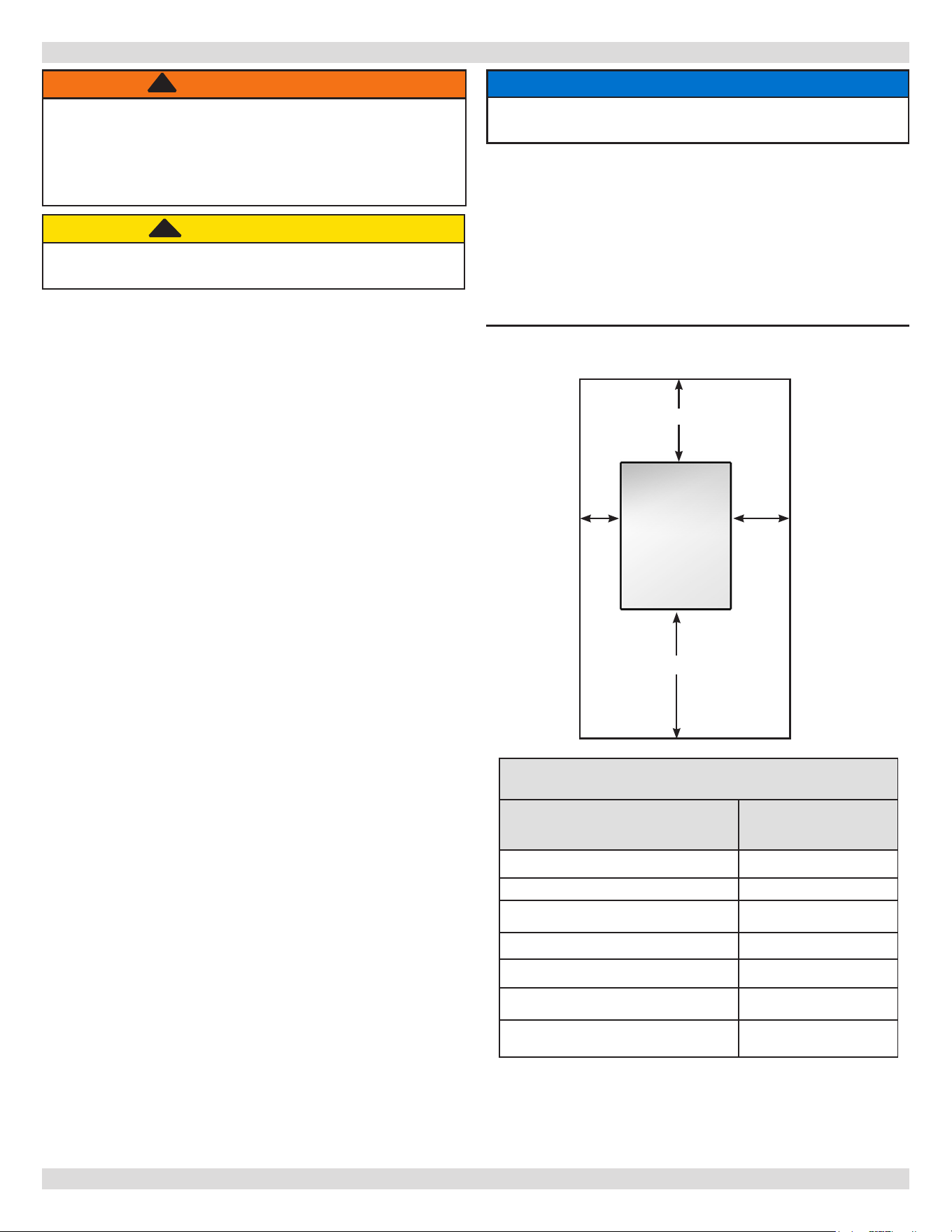
Table 1 - BOILER MINIMUM CLEARANCE TO
COMBUSTIBLES
Unit
Minimum
Clearances
Top
6” (152 mm)
Rear
6” (152 mm)
Right 8” (203 mm)
Left 6” (152 mm)
Front (Alcove) 18” (457 mm)
Flue/Vent Connector 6” (152 mm)
Near Boiler Piping 1” (24 mm)
Set unit on concrete or other noncombustible material base or
oor. DO NOT INSTALL ON CARPETING.
Figure 1 - Minimum Clearances To Combustible
Construction
* Denition of Alcove is three sided space with no wall in
front of boiler. ANSI standard for alcove is 18 inches from
front of appliance to leading edge of side walls as shown
above.
8”
Boiler
Rear
Front
Right
LEFT
18”
6”
8”
6”
CAUTION
Boiler weight exceeds 200 pounds (90.7 kg). Do not
lift boiler without assistance.
!!
WARNING
Fire hazard. Do not install boiler on combustible
ooring or carpeting. Refer to (Combustible Floor
Addendum) included in literature envelope provide
with boiler. Failure to follow these instructions could
result in death or serious injury.
!
3�1 Installation Requirements
(Combustible Floor Addendum) included in literature
envelope provide with boiler and outlined in National
Fuel Gas Code, ANSI Z223.1/NFPA 54. Do Not Install
Boiler on carpeting�
11.
Verify boiler is supplied with correct type of gas, fresh
air for combustion, and suitable electrical supply.
PN 240013101 Rev. B [08/08/2023]
8
3 - LOCATING THE BOILER
• Ambient room temperature always above 32°F (0°C) to
prevent the potential of freezing.
• Drainage of water (or water/ antifreeze solution) during
boiler service or from safety relief valve discharge.
• Access to system water piping, gas supply, and
electrical service.
• Boiler shall be installed on at level surface which is
capable of supporting the weight of the boiler, water,
and equipment.
• Raise boiler above the oor on blocks if oor may get
wet.
• Water, gas, and electrical connect to right side of
boiler.
Table 2 - CONTAMINANTS
Items to Avoid
Products Which May Contain These
Items
Areas Where These Items May Be
Found
Chlorine, Fluorine, and Compounds
Spray cans containing chlorouorocarbons
Chlorinated waxes/cleaners
Chlorine-based swimming pool chemicals
Calcium chloride used for thawing
Sodium chloride used for water softening
Swimming pool or spa chemicals
De-icing salts or chemicals
Carbon Tetrachloride
Swimming pools and pool storage areas
Laundry room (Note 2)
Conned storage areas
Airborne Particulates
Drywall dust
Road or gravel dust
Dryer lint
Cat litter
Construction or remodelling areas (Note 1)
Laundry room (Note 2)
Acids, Solvents, etc.
Paint, Varnish, Turpentine, etc.
Cleaning Solvents
Hydrochloric acid/muriatic acid
Cements, adhesives and glues
Photo processing plants
Garages with workshops
Furniture renishing areas and
establishments
Laundry Chemicals
Laundry detergents, bleaches, fabric
softeners, etc.
Antistatic fabric softeners (dryer sheets)
Dry cleaning/laundry areas and
establishments
Other
Permanent wave solutions
Refrigerants (Freon, etc) (only where
the refrigerant may be leaking from the
appliance)
Beauty shops
Refrigeration repair shops
Notes:
1. It is recommended the boiler be isolated and not operated during construction/
renovation. Excessive particles ingested by the boiler may accumulate in the ueway
passages possibly resulting in unsafe operation. In this case, unit servicing shall include
cleaning of ueway passages and burner ports.
2. If locating boiler in laundry room is unavoidable, it is manufacturer recommended
the room be generously ventilated (well in excess of combustible air requirements), and
homeowner seal laundry supply containers, and minimize room vapors.
3. Piping allowing fresh air in should also be considered. See Section 5-1.
• Horizontal run to chimney shall be as short as possible.
• System piping exposed to freezing conditions: Use
inhibited propylene glycol solutions certied by uid
manufacturer for use with closed water heating system.
Do not use automotive or ethylene glycol.
3�2 Boiler Location Considerations
PN 240013101 Rev. B [08/08/2023]
9
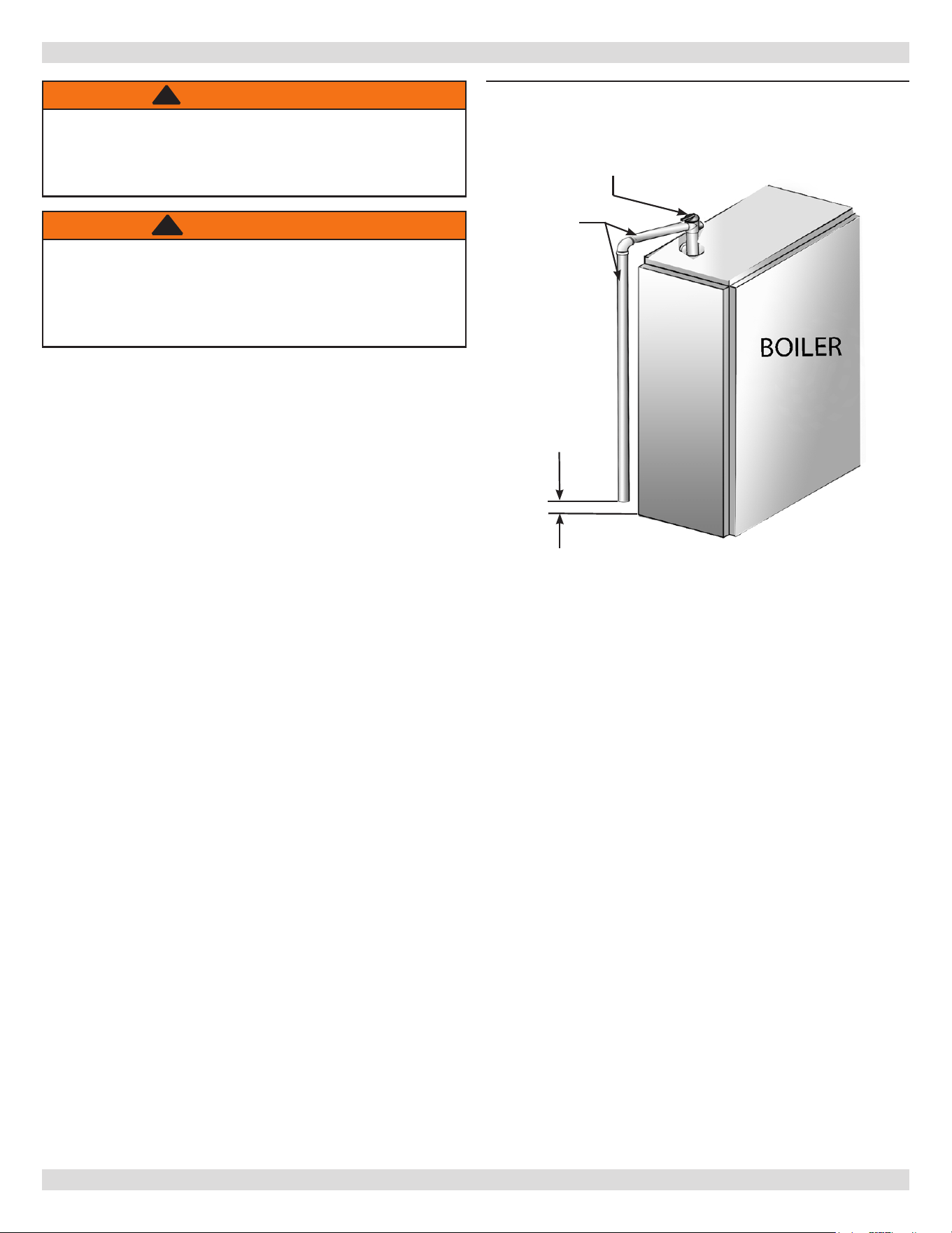
4 - CONNECTING SUPPLY AND RETURN PIPING
Check local codes
for maximum
distance from
oor or other
allowable safe
point of discharge
ASME RELIEF VALVE
DISCHARGE
PIPING
Figure 2 - Safety Relief Valve Discharge Piping
1.
Refer to local codes and appropriate ASME Boiler
and Pressure Vessel Code for additional installation
requirements. Install safety relief valve using pipe
ttings provided with boiler. See Figure 2.
2.
Install safety relief valve with spindle in vertical
position.
3.
Do not install shuto valve between boiler and safety
relief valve.
4.
Install discharge piping from safety relief valve. See
Figure 2.
• Use ¾” or larger pipe.
• Use pipe suitable for temperatures of 375°F (191°C)
or greater.
• Individual boiler discharge piping shall be independent
of other discharge piping.
• Size and arrange discharge piping to avoid reducing
safety relief valve relieving capacity below minimum
relief valve capacity stated on rating plate.
• Run pipe as short and straight as possible to location
protecting user from scalding and properly drain
piping.
• Install union, if used, close to safety relief valve outlet.
• Install elbow(s), if used, close to safety relief valve
outlet and downstream of union (if used).
• Terminate pipe with plain end (not threaded).
WARNING
Burn and scald hazard! Safety relief valve shall be
installed with spindle in upright position only,
following ASME BPV code. Failure to follow these
instructions could result in death or serious injury.
!
4�1 Safety Relief Valve Installation
WARNING
Burn and scald hazard. Safety relief valve could
discharge steam or hot water during operation.
Install discharge piping per these instructions. Failure
to follow these instructions could result in death or
serious injury.
!
PN 240013101 Rev. B [08/08/2023]
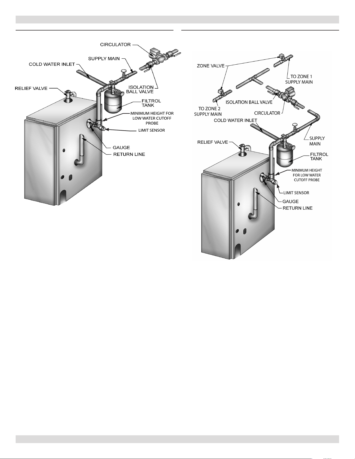
10
LIMIT SENSOR
MINIMUM HEIGHT FOR
LOW WATER CUTOFF
PROBE
Figure 3 -
Forced Hot Water Typical Piping
LIMIT SENSOR
MINIMUM HEIGHT
FOR LOW WATER
CUTOFF PROBE
Figure 4 - Forced Hot Water Typical Piping
With Zone Control Valve
4 - CONNECTING SUPPLY AND RETURN PIPING
PN 240013101 Rev. B [08/08/2023]
11
• Install radiation units (panels, radiators or cabinets) and
supply and return mains rst then make connections at
boiler.
• Verify clean water supply is available when connecting
cold water supply to water valve. Install sand strainer at
pump when water supply is from well or pump.
• Provide low water cuto device when boiler is installed
above radiation level or as required by the Authority
having jurisdiction, either provide as part of boiler
or at time of boiler installation. Periodic inspection
is necessary, as is ushing of oat type devices, per
manufacturers specic instructions. Refer to Figures 3
& 4 for minimum height for installation of LWCO. Refer
to parts manual for LWCO kit. When using LWCO other
than kit listed in parts manual follow specic LWCO
manufacturer instructions.
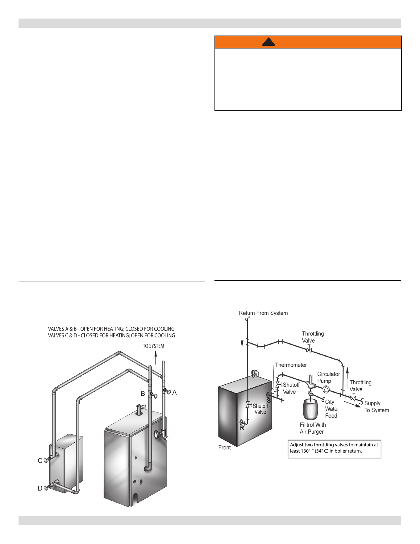
• Boiler used in connection with refrigeration systems
shall be installed so chilled medium is piped in parallel
with heating boiler with appropriate valves to prevent
chilled medium from entering heating boiler.
See
Figure 5
.
• Boiler connected to heating coils located in air handling
units exposed to refrigerated air circulation, piping
system shall be equipped with ow control valves or
other automatic means to prevent gravity circulation of
boiler water during cooling cycle.
Figure 5
- Piping Arrangements For Boiler When
Used In Connection With Refrigeration
System
Low Design Water Temperature Systems (Below
150°F) And Large Water Content Systems
Condensation is corrosive and can eventually cause severe
damage to boiler and venting system.
• Minimum design return water temperature to prevent
condensation in boiler and venting is 130°F. Minimum
high limit setting is 150°F.
• Boiler used in heating systems where design water
temperatures below 150°F are desired (e.g. radiant oor
heating), a 3-way or 4-way mixing valve or suitable
alternative is required to prevent low temperature return
water from entering boiler. When using mixing valve,
follow manufacturer’s installation instructions.
• Boiler connected to system having large water content
(such as former gravity system), suggest use of bypass
piping. See
Figure
6
.
Adjust two throttling valves to maintain at
least 130° F (54° C) in boiler return.
Figure 6
- Bypass Piping
4 - CONNECTING SUPPLY AND RETURN PIPING
WARNING
Asphyxiation hazard! Gradual ueway blockage
resulting from condensate induced corrosion may
block boiler passages, resulting in carbon monoxide
and or ame rollout. Install bypass piping if return
temperature is under 130°F. Failure to follow these
instructions could result in death or serious injury.
!
4�2 Supply and Return Requirements
PN 240013101 Rev. B [08/08/2023]
12
5 - VENTILATION & COMBUSTION AIR
Provide combustion air and ventilation air in accordance
with the section “Air for Combustion and Ventilation,”
of the National Fuel Gas Code, ANSI Z223.1/NFPA 54
Provide make-up air where exhaust fans, clothes dryers,
and kitchen ventilation equipment interfere with proper
operation. If inadequate makeup air is suspected it is
always acceptable to add additional ventilation.
National Fuel Gas Code recognizes several methods
of obtaining adequate ventilation and combustion air.
Requirements of the authority having jurisdiction may
override these methods.
• Engineered Installations. Must be approved by
authority having jurisdiction.
• Mechanical Air Supply. Provide minimum of 0.35 cfm
per (Btu/hr)/1000 for all appliances located within
space. Additional requirements where exhaust fans
installed. Interlock each appliance to mechanical air
supply system to prevent main burner operation when
mechanical air supply system not operating.
• All Indoor Air. Calculate minimum volume for all
appliances in space. Use a dierent method if
minimum volume not available.
A. Standard Method. Cannot be used if known air
inltration rate is 0.40 air changes per hour. See
Table 3 for space with boiler only. Use equation for
multiple appliances.
Volume ≥ 50 ft
3
x Total Input (Btu/hr)/1000
B. Known Air Inltration Rate. See Table 5-1 for
space with boiler only. Use equation for multiple
appliances. Do not use an air inltration rate
(ACH) greater than 0.60.
Volume ≥
21 ft
3
/ACH x Total Input (Btu/hr)/1000
C. Refer to National Fuel Gas Code for opening
requirements between connected indoor spaces.
• All Outdoor Air. Provide permanent opening(s)
communicating directly or by ducts with outdoors.
A. Two Permanent Opening Method. Provide opening
commencing within 12 inches of top and second
opening commencing within 12 inches of bottom of
enclosure.
Direct communication with outdoors or
communicating through vertical ducts. Provide
minimum free area of 1 in² per 4,000 Btu/hr of
total input rating of all appliances in enclosure.
Communicating through horizontal ducts.
Provide minimum free area of 1 in² per 2,000
Btu/hr of total input rating of all appliances in
enclosure.
B. One Permanent Opening Method. Provide opening
commencing within 12 inches of top of enclosure.
Provide minimum clearance of 1 inch on sides/back
and 6 inches on front of boiler (does not supersede
clearance to combustible materials).
• Refer to National Fuel Gas Code for additional
requirements for louvers, grilles, screens and air ducts.
• Combination Indoor and Outdoor Air. Refer to National
Fuel Gas Code for application information.
National Gas and Propane Installation Code Requires
providing air supply in accordance with:
• Section 8.2 and 8.3 when combination of
appliances has a total input of up to and including
400,000 Btu/hr (120 kW).
• Section 8.4 when combination of appliances has total
input exceeding 400,000 Btu/hr (120 kW).
• Refer to Natural Gas and Propane Installation Code
for specic air supply requirements for enclosure
or structure where boiler is installed, including air
supply openings and ducts.
Table 3 - Air Inltration ( ft3/h)
Input
(Btu/hr)
Standard
Method
Known Air Inltration Rate Method (ACH - Air Changes Per Hour)
0�1 0�2 0�3 0�4 0�5 0�6
42,500 2125 6375 3188 2125 1594 1275 1063
75,000 3750 11250 5625 3750 2813 2250 1875
112,500 5625 16875 8438 5625 4219 3375 2813
150,000 7500 22500 11250 7500 5625 4500 3750
187,500 9375 28125 14063 9375 7031 5625 4688
WARNING
Asphyxiation Hazard! Provide enough air openings
to boiler/combustion area to dilute ue gases
and allow for consistent, quality combustion.
Do not obstruct air openings. Follow instructions
below, to maintain adequate combustion air.
Failure to follow these instructions could result in
ignition failure, overheating, carbon monoxide, and
accumulation of ue gases.
!
5�1 Requirements
PN 240013101 Rev. B [08/08/2023]

13
When an existing boiler is removed from a common
venting system, the common venting system is likely to be
too large for proper venting of the appliances remaining
connected to it. If this occurs, follow this test procedure:
At the time of removal of an existing boiler, the following
steps shall be followed with each appliance remaining
connected to the common venting system placed in
operation, while the other appliance remaining connected
to the common venting system are not in operation.
1.
Seal any unused openings in the common venting
system.
2.
Visually inspect the venting system for proper size and
horizontal pitch and determine there is no blockage or
restriction, leakage, corrosion and other deciencies
which could cause an unsafe condition.
3.
Insofar as is practical, close all building doors and
windows and all doors between the space in which the
appliances remaining connected to the common venting
system are located and other spaces of the building.
Turn on clothes dryers and any appliance not connected
to the common venting system. Turn on any exhaust
fans, such as range hoods and bathroom exhausts, so
they will operate at maximum speed. Do not operate a
summer exhaust fan. Close replace dampers.
4.
Place in operation the appliance being inspected. Follow
the lighting instructions. Adjust thermostat so appliance
will operate continuously.
5.
Test for spillage at the draft hood relief opening after 5
minutes of main burner operation. Use ame of a match
or candle, or smoke from a cigarette, cigar, or pipe.
6 - VENT SYSTEM MODIFICATION
6.
After it has been determined that each appliance
remaining connected to the common venting system
properly vents when tested as outlined above, return
doors, windows, exhaust fans, replace dampers and any
other gas-burning appliance to their previous conditions
of use.
7.
Any improper operation of the common venting system
should be corrected so the installation conforms with
the National Fuel gas Code, ANSI Z223.1/NFPA 54
When re-sizing any portion of the common venting
system, the common venting system should be re-sized
to approach the minimum size determined using the
appropriate tables in Chapter 13 of the National Fuel
Gas Code, ANSI Z223.1/NFPA 54
8.
The existing venting system shall be checked to ensure
it meets local codes.
6�1 Removal of Existing Boiler From Venting
System
PN 240013101 Rev. B [08/08/2023]
14
Chimney must be clean, right size, properly constructed
and in good condition. A chimney shall be lined in a manner
acceptable to the authority having jurisdiction.
1.
Installation must conform to requirements of the
authority having jurisdiction or, in absence of such
requirements, to the National Fuel Gas Code, ANSI
Z223.1/NFPA 54, or applicable provisions of the local
building codes.
2.
Boiler’s induced draft blower has 3” outlet. 3” X
4” increaser tting is included in parts bag. Locate
increaser tting on outlet of induced draft blower, and
secure gas-tight with bead of furnished silicone sealant.
Increaser tting is required on this boiler for Category I
venting, and 4” is minimum permissible vent diameter.
This does not imply vent connector is intended to be 4”
diameter pipe. Vent connector shall be sized according
to appropriate venting tables in the National Fuel
Gas Code and may be required to be larger than 4”
diameter.
3.
These are high eciency boilers with low stack or
exhaust temperature.
4.
Venting into masonry chimney without liner, line
chimney from top to bottom with either:
A. Listed Type B vent pipe
B. Listed exible vent liner
C. Poured ceramic liner.
5.
Outside chimneys should not be used unless they are
(choose one of the following):
A. Enclosed in a chase
B. Lined with Type B vent pipe
C. Use listed exible vent liner
D. Use certied chimney lining system
6.
Vent connector from boiler to chimney should run as
directly as possible with as few elbows as possible.
7.
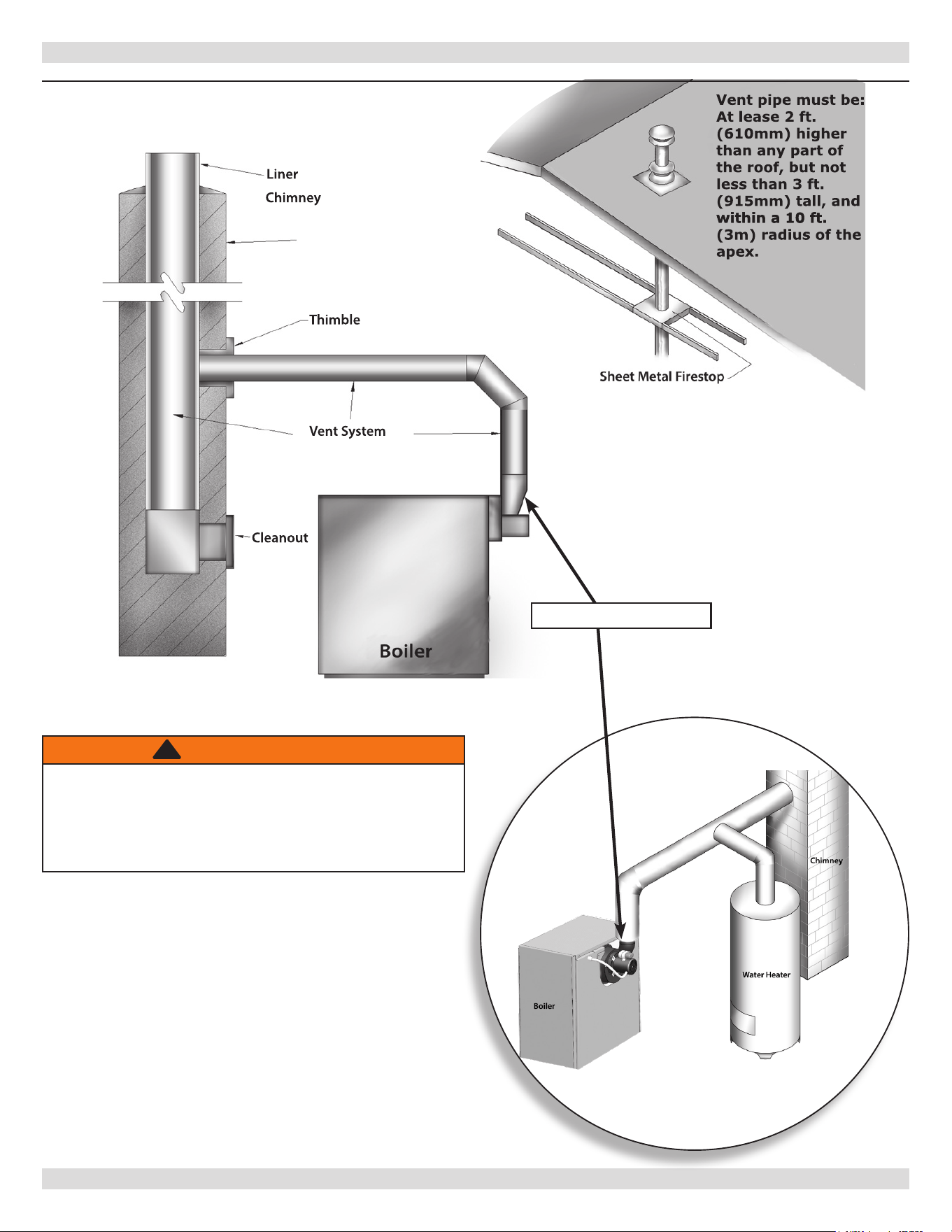
Where possible, it is recommended to common vent
water heater and boiler. Consult appropriate Vent
Sizing Tables in National Fuel Gas Code for specic
requirements of multiple appliance venting.
8.
When boiler is only appliance connected to vent, Type
B vent pipe is recommended for vent connector.
9.
For horizontal runs slope pipe up from boiler to vent
terminal not less than 1/4” in/ft (21 mm/m).
10.
End of vent pipe must be ush with inside face of
chimney ue. Use sealed-in thimble for chimney
connection.
11.
Fasten sections of vent pipe with 3 sheet metal screws
at each joint to make rigid.
12.
Use stovepipe wires or metal strapping every 5’ to
support pipe from above.
13.
Do not connect to replace ue.
14.
Do not install damper on this boiler.
• Use Type B vent pipe through crawl space. Where vent
pipe passes through combustible wall or partition, use
ventilated metal thimble. Thimble should be 4 inches
larger in diameter than vent pipe.
• Boiler installed with single wall vent, must have 6”
clearance between its surface and any combustible
material. New Type B gas vent or exible liner must be
installed in accordance with instructions furnished with
vent. Maintain clearances as specied for vent pipe.
• Verify vent pipe is re-stopped where it goes through
oor or ceiling. It should have approved vent cap with
clearances from roof. If clearances are less than shown,
have vent checked by local authorities. Figure 7.
7 - VENT INSTALLATION
WARNING
Boiler and venting installations shall be performed
by a qualied expert and in accordance with the
appropriate manual. Installing or venting boiler
or other gas appliance with improper methods or
materials may result in serious injury or death due
to re or to asphyxiation from poisonous gases such
as carbon monoxide which is odorless and invisible.
!
WARNING
Do not connect boiler to any portion of mechanical
draft system operating under positive pressure.
!
NOTICE
Minimum Vent Pipe Clearance - Wood and other
combustible materials shall not be closer than 6”
from any surface of single wall metal vent pipe.
Listed Type B vent pipe or other listed venting
systems shall be installed in accordance with their
listing.
NOTICE
Boiler installation for chimney venting is not
complete unless increaser tting is located and
secured.
7�1 Chimney Venting (Category I)
7�2 Requirements
PN 240013101 Rev. B [08/08/2023]
15
WARNING
3” x 4” increaser is required for Category I venting.
Failure to follow these instructions could result in
asphyxiation from poisonous gases such as carbon
monoxide which is odorless and invisible and may
result in serious injury or death.
!
7 - VENT INSTALLATION
Liner
Chimney
Thimble
Vent System
Cleanout
Boiler
Vent pipe must be:
At lease 2 ft.
(610mm) higher
than any part of
the roof, but not
less than 3 ft.
(915mm) tall, and
within a 10 ft.
within a 10 ft.
(3m) radius of the
apex.
CHECK YOUR CHIMNEY
For boilers connection to gas vents or chimneys,
vent installations shall be in accordance with
“Venting of Equipment”, of the National Fuel
Gas Code, ANSI Z223.1/NFPA 54, or applicable
provisions of the local building codes.
Figure 7 - Type B Gas Vent
3”x4” Increaser
PN 240013101 Rev. B [08/08/2023]
16
Horizontal Requirements (Category III) venting
systems must be installed in accordance with
these instructions�
Maximum Horizontal Vent Length For Stainless Steel Vent
Pipe - 30’ Plus One 90º Elbow Plus Vent Terminal.
Minimum Horizontal Vent Length - 2’ Plus One 90º Elbow
Vent Termination.
Additional elbows are equivalent to 6 feet of straight pipe
for 4” diameter 90° elbow or 3 feet of straight pipe for 3”
diameter 90° elbow. 2, 3, 4, 5, Section Boilers use 3” vent
pipe; for 6 Section Boilers use 4” vent pipe.
CHOICE OF VENT PIPE MATERIAL
• U. L. Listed Z-Flex Z-Vent Stainless Steel Vent Pipe.
• U. L. Listed Heat-Fab Saf-T-Vent Stainless Steel Vent
Pipe.
• U. L. Listed Flex-L Star-34 Stainless Steel Vent Pipe.
• U. L. Listed ProTech Systems FasNSeal Stainless Steel
Vent Pipe.
For appliance adapter and terminations, that fit your
specific installation needs, contact the approved
vent material manufacturer listed under CHOICE OF
VENT PIPE MATERIAL.
INDUCED DRAFT HIGH EFFICIENCY BOILERS
8 - HORIZONTAL VENTING INSTRUCTIONS
Figure 8 - Induced Draft High Eciency Boilers
(21 mm/m)
(300 mm)
(21 mm/m)
(300 mm)
8�1 Horizontal Venting (Category III)
PN 240013101 Rev. B [08/08/2023]

17
1.
Boilers may be vented horizontally as shown in
Figure 8�
Vent pipe is pitched
down
from boiler to
vent termination. Do not connect other appliances to
this vent.
2.
Vent Pipe Material:
A. UL Listed Z-Flex Z-Vent stainless steel vent pipe
from boiler to vent termination,
-or-
B. UL Listed Heat-FabSaf-T-Vent stainless steel vent
pipe from boiler to vent termination,
-or-
C. UL Listed Flex-L StaR-34 stainless steel vent pipe
from boiler to vent termination,
-or-
D. UL Listed ProTech FasNSeal stainless steel vent
pipe from boiler to vent termination.
3.
Clearance to Combustible Materials: For stainless steel
vent pipe maintain 6” minimum air space clearance to
combustible materials.
4.
Vent Pipe Size:
A. 2, 3, 4 and 5 section boilers use 3” vent pipe
connected directly to the outlet of the induced draft
blower.
B. 6 section boilers use 4” vent pipe, starting with
a 3” to 4” stainless steel vent pipe transition that
is connected directly to the outlet of the induced
draft blower. Do not use 3” vent pipe on 6 section
boilers.
5.
Vent Pipe Length:
A. For stainless steel vent pipe, the maximum
horizontal vent length is 30 feet plus one 90
°
elbow
plus termination tting.
B. Minimum horizontal vent length for all vent
materials is 2 feet plus one 90° elbow plus
termination tting.
C. For additional elbows reduce the maximum vent
length as shown:
• 3” - 90° elbow - reduce vent length 3 feet per
each 3” elbow
• 4” - 90° elbow - reduce vent length 6 feet per
each 4” elbow
Example:
6 section boiler has 3 elbows plus the
termination tting. This means 2 additional 4” elbows will
be used, at 6 feet per elbow. This is equivalent to 12 feet
of pipe (2 x 6 =12), therefore maximum vent length is now
18 feet (30 -12 =18).
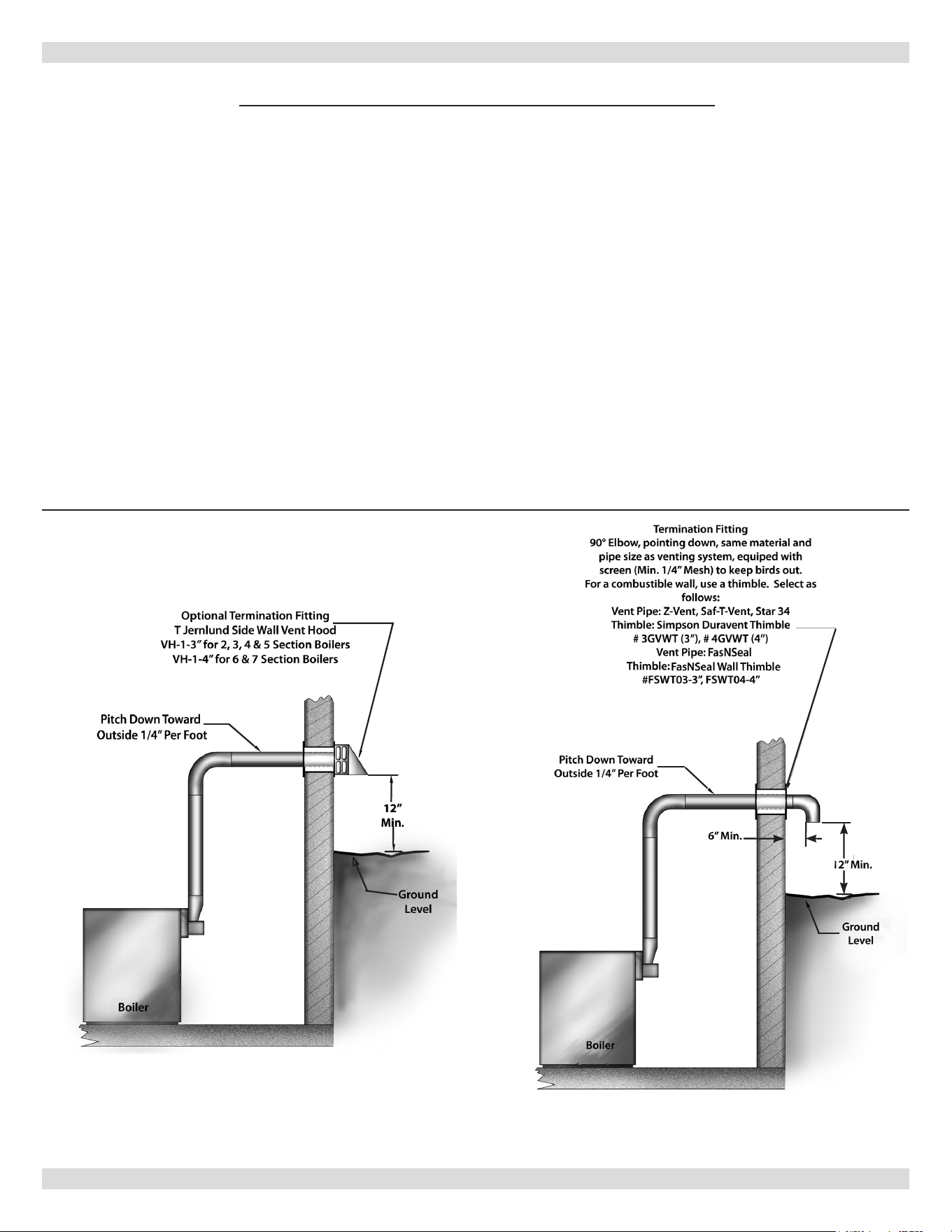
6.
Vent Termination Fitting: For all vent pipe materials,
you may use either:
A. A 90° elbow pointing down, tted with a minimum
1/4” mesh screen to keep out rodents and birds.
The elbow shall be of the same material and size
as vent pipe. The elbow exit should be at least 6”
away from exterior wall as shown in
Figure 8
.
-or-
B. Tjernlund VH-1 Series side wall vent hood. For 2,
3, 4, 5 section boilers use VH-1-3”. For 6 section
boilers use VH-1-4”.
7.
Vent Pipe Termination Location
See Figure 9
:
A. When venting through combustible walls,
combustible clearances must be considered. The
VH-1 Side wall vent hood provides both the outside
vent termination and a double wall pipe for passing
through a combustible wall up to 8” thick (VH-
1-4”) or 9” thick (VH-1-3”). The hole in the wall
must be 6¼” square for 3” vent pipe and 7 1/2”
square for 4” vent pipe, in order to insert the VH-1
side wall vent hood. The VH-1 may also be used in
noncombustible walls.
B. If the 90° elbow is the termination tting of choice,
then the single wall pipe will be passing through
the side wall. For combustible walls, a UL listed
thimble shall be used where the single wall pipe
passes through the wall. For combustible walls
using Z-Vent, Saf-T-Vent, or StaR-34 vent pipe,
use the following:
• 3” vent pipe - use Simpson’s Duravent 3” thimble
• 4” vent pipe - use Simpson’s Duravent 4” thimble.
Maximum wall thickness with this thimble is 7
inches.
For combustible walls using ProTech FasNSeal where the
single wall vent pipe must pass through the side wall, a UL
Listed FasNSeal wall thimble shall be used.
The thimble is adjustable for dierent wall thickness, with a
maximum wall thickness of 7 inches. Seal the thimble along
the outside edge of the plate with caulk or silicone and
fasten to the wall with screws or nails.
C. For single wall pipe through non-combustible
walls, the hole through the wall need only be large
enough to maintain the pitch of the vent pipe, and
provide proper sealing. A thimble is not required
for single wall pipe passing through noncombustible
walls.
8 - HORIZONTAL VENTING INSTRUCTIONS
PN 240013101 Rev. B [08/08/2023]
18
D. Vent Termination
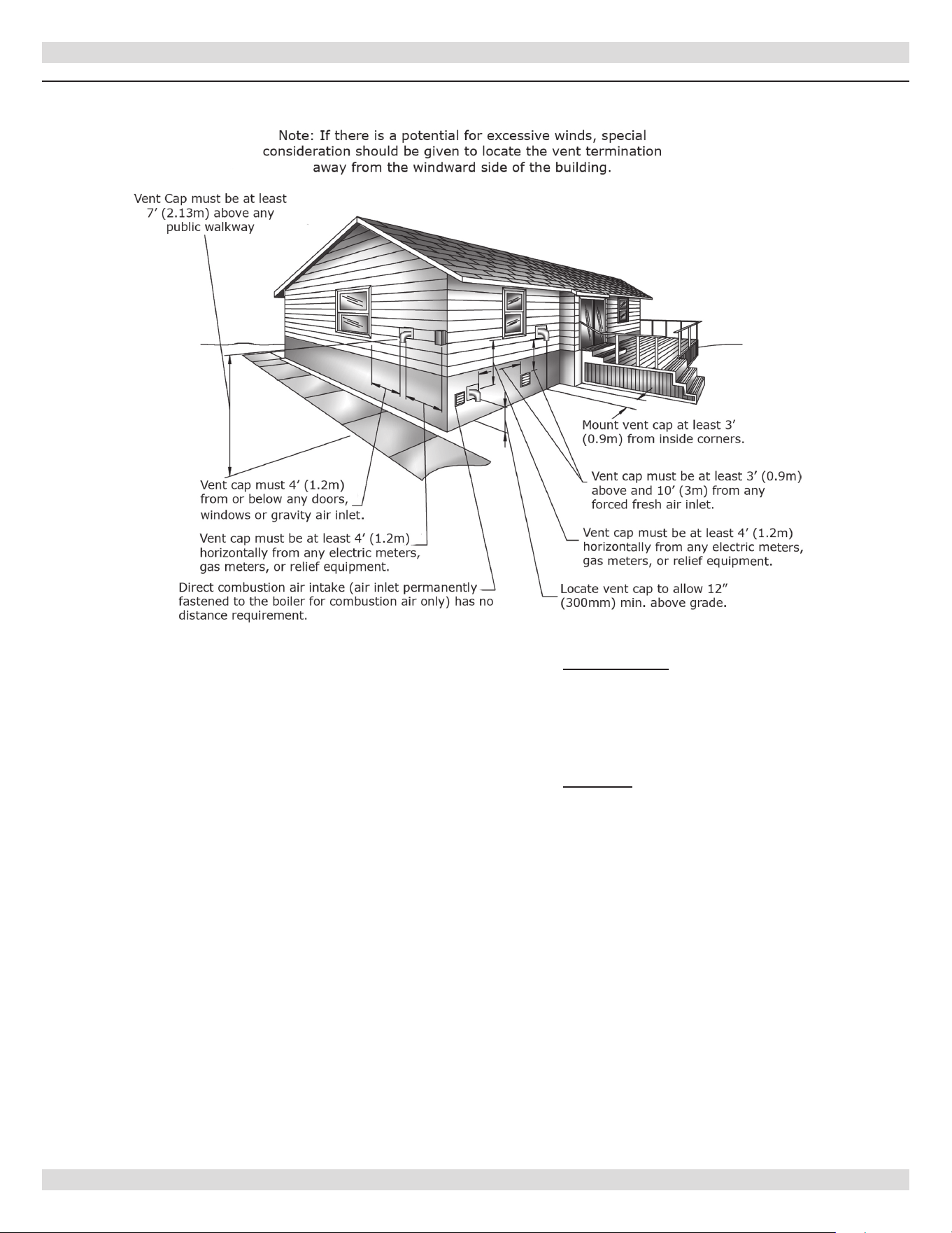
о Venting system shall terminate at least 3 feet
(0.9 m) above any forced air inlet located within
10 feet (3 m).
о Venting system shall terminate at least 4 feet
(1.2 m) below, 4 feet (1.2 m) horizontally from,
or 1 foot (300 mm) above any door, window, or
gravity air inlet into any building.
о Bottom of vent shall be located at least 12
inches (300 mm) above grade.
о Termination of vent shall be not less than 7 feet
(2.13 m) above adjacent public walkway.
о Vent terminal shall not be installed closer than
3 feet (0.9 m) from inside corner of L shaped
structure.
о Termination of vent should be kept at least 3
feet (0.9 m) away from vegetation.
о Venting system shall not terminate underneath
any deck, patio, or similar structure.
8 - HORIZONTAL VENTING INSTRUCTIONS
Figure 9 - Horizontal Venting Clearances
о United States - Terminate vent system at least
4 feet (1.22 m) horizontally from, and in no
case above or below, unless a 4 feet (1.22m)
horizontal distance is maintained, from electric
meters, gas meters, regulators and relief
equipment. See Figure 9.
о Canada - Terminate vent system at least 6
feet (1.83 m) horizontally from, and in no case
above or below,unless 6 feet (1.83 m) horizontal
distance is maintained, from gas and electric
meters, regulators and relief equipment.
о Venting system shall terminate at least 4 feet
below any eave, sot, or roof overhang.
о Place vent on wall away from prevailing winter
wind. Locate or guard vent to prevent accidental
contact with people or pets.
о Terminate vent above normal snow-line. Avoid
locations where snow may drift and block vent.
Ice or snow may cause boiler to shut down if
vent becomes obstructed.
о Under certain conditions, ue gas will condense,
forming moisture. Take steps to prevent building
materials at vent terminal from being damaged
by exhaust of ue gas.
PN 240013101 Rev. B [08/08/2023]

19
8.
Joining and Sealing the Vent Pipe:
The vent pipe needs to be both watertight and gas
tight. Seal all joints and seams as follows:
A. For Z-Flex Z-Vent stainless steel vent pipe use
a high temperature silicone sealant rated for
550°F. The outside of the male end and inside
of the female end of the pipe must be cleaned
with brake cleaner before applying silicone bead.
For 3” vent pipe runs begin with the male end
of the vent pipe over the boilers induced draft
blower outlet. For 4” vent pipe runs begin with a
6” length of 3” Z-Vent over the boiler’s induced
draft blower outlet, to which an even bead of high
temperature silicone sealant should be applied.
Then connect the 3” Z-Vent to a Z-Vent 3” to 4”
reducer. Then continue the 4” Z-Vent pipe run by
connecting the 4” male end of the Z-Vent to the
reducer. (A locking band may be used around this
joint for additional support.) Then following the
sealing instructions, push the 4” male end of the
Z-Vent over the 4” increaser tting. When using
the Tjernlund VH-1 vent hood, the female end
(ared end) of the vent pipe will be connected to
the termination hood. The male end of the vent
hood must be crimped before pushing the Z-Vent
over the vent hood’s connecting pipe. Before the
pipes are joined, apply a ¼” bead of silicone one
inch from the end of the male end. Then push the
pipes together as far as they will go making sure
any seams are aligned and oriented upward. Now
apply another bead of silicone around this joint and
smooth out. Then use a Z-Flex locking band around
the center of the joint.
1. Apply the high temperature silicone
approximately one inch from the end, around
the male end of the pipe in an even ¼” bead.
2. Pipes can now be pushed together as far as they
will go. The seams on pipe should be aligned
and oriented upward in all horizontal appliances.
Apply another bead of silicone around this joint
and smooth out.
3. Slide locking band over center of joint and
tighten gear clamps. Make sure locking band is
centered on joint.
4. Check all joints and seams for gas tightness.
5. Horizontal venting shall have slope not less
than ¼” every 12 inches (21 mm/m) downward
away from the boiler to prevent collection of
condensate throughout the assembly.
6. Allow sealant to cure for 24 hours before
operating appliance.
B. For Heat-Fab Saf-T-Vent stainless steel vent pipe
use a high temperature silicone sealant rated for
550°F The outside of the male end and inside
of the female end of the pipe must be cleaned
before applying the silicone bead. For 3” vent
pipe runs, the male end of the vent pipe which
goes over the outlet of the boiler’s induced draft
blower must be crimped. The vent pipe should be
crimped as minimal as possible to provide a tight
t over the outlet. After crimping is completed
follow the instructions for applying silicone sealant.
For 4” vent pipe runs, begin with a Saf-T-Vent 3”
to 4” increaser tting over the boiler’s induced
draft blower outlet, to which an even bead of high
temperature silicone sealant should be applied.
Then continue the 4” Saf-T-Vent pipe run by
connecting the 4” male end of the Saf-T-Vent to the
increaser. (A locking band may be used around this
joint for additional support.) The vent ow must be
in the direction indicated on the vent pipe. When
using the Tjernlund VH-1 vent hood, the female
end (ared end) of the vent pipe will be connected
to the termination hood. Apply high temperature
silicone in an even ¼” bead approximately ¼” to
⅜” from the end of the vent hood’s connecting
vent pipe. Also, run a similar size bead of silicone
sealant down the seam weld of the vent pipe.
Then push the female end over the vent hood’s
connecting vent pipe.
1. Apply the high temperature silicone around
the male end of the pipe (without the tabs)
in an even ¼” bead. Silicone bead should be
approximately ¼” to ⅜” from the end of the
male end. Also, run a similar size bead of
silicone sealant down the seam weld at the end
of each joint.
2. Pipes can now be pushed together as far as they
will go. The seams on the vent pipe should be
aligned and oriented upward in all horizontal
appliances. With a moistened nger or at tool,
spread any sealant that squeezes out around the
circumference of the joint.
3. Attach the sections together with the locking
rings and tabs (except at the blower outlet
where no locking ring exists.) Inspect the
joint to ensure that ue gases will not leak. If
necessary apply additional sealant around the
joint.
4. Horizontal venting shall have a slope not less
than ¼” every 12 inches (21 mm/m) downward
away from the boiler to prevent collection of
condensate throughout the assembly.
5. Allow the sealant to cure for 24 hours before
operating the appliance.
8 - HORIZONTAL VENTING INSTRUCTIONS
PN 240013101 Rev. B [08/08/2023]

20
C. For Flex-L StaR-34 stainless steel vent pipe use
a high temperature silicone sealant rated for
550°F. Before applying silicone, the outside of
the male end and inside of the female end of the
pipe must be cleaned using a cleaner, such as
methyl ethyl ketone (MEK) or naphtha. For 3”
vent pipe runs, begin with the male end of the
vent pipe over the boiler’s induced draft blower
outlet. For 4” vent pipe runs begin with a StaR-34
3” to 4” increaser tting over the boiler’s induced
draft blower outlet. For both 3” and 4” vent pipe
runs, apply a bead of silicone sealant around the
blower outlet and around the inside of the male
end of vent pipe going over the blower’s outlet.
When using the Tjernlund VH-1 vent hood,
the female end (ared end) of the vent pipe
will be connected to the termination hood.
Apply high temperature silicone in an even ¼”
bead approximately ¼” from the end of the vent
hood’s connecting vent pipe. Also, run a similar size
bead of silicone sealant down the seam weld of the
vent pipe. Then push the female end over the vent
hood’s connecting vent pipe. Now ll in the channel
inlet with silicone sealant. Do not try to insert the
joiner band, instead fasten the vent pipe to the
vent hood’s pipe with a steel gear clamp.
1. Apply the high temperature silicone around
the male end of the pipe in an even ¼” bead.
Silicone bead should be approximately ¼” from
the end of the male end. Also, run a similar size
bead of silicone sealant down the seam weld at
the end of each joint.
2. The seams on the vent pipe should be aligned
and oriented upward in all horizontal vent pipe
runs.
3. Insert the male end of one into the female end
of the other. Push the pipe together so the
female end rests up against the stop bead of the
male end.
4. Insert a StaR-Joiner Band into the inlet of the
beaded channel. Feed the Joiner Band in so
it makes its way around the pipe, back to the
channel inlet and it overlaps itself by about ½”.
5. Cut the excess Joiner Band so it lays at in the
beaded channel. Fill the inlet of the beaded
channel with high temperature silicone. Smooth
out the silicone over the channel inlet and the
silicone between the female end and the stop
bead of the male end.
6. Horizontal venting shall have a slope not less
than ¼” every 12 inches (21 mm/m) downward
away from the boiler to prevent collection of
condensate throughout the assembly.
7. Allow the sealant to cure for 24 hours before
operating the appliance.
D. For ProTech Systems FasNSeal stainless steel
vent pipe no cleaning uid is required. For 3”
vent pipe runs on 2, 3, 4 and 5 section boilers,
begin by locating the FasNSeal Ametek Adapter
over the boiler’s induced draft blower. Continue
t h e v e n t p i p e r u n w i t h 3 ” F a s N S e a l v e n t p i p e .
For 6 section boilers, begin by locating the
FasNSeal Ametek Adapter over the boiler’s induced
draft blower. Then connect a FasNSeal 3” to 4”
increaser to the 3” adapter outlet. Continue the
vent pipe run with 4” FasNSeal vent pipe. Other
than the Ametek Adapter and increaser tting,
DO NOT use 3” vent pipe on 6 section boilers.
FasNSeal vent pipe is joined and sealed by the
use of an internal sealing gasket and a locking
band on the female end of each vent pipe. All
components should be examined for possible
shipping damage prior to installation. Align all vent
pipe seams and orient upward in all horizontal
applications. Adjustable vent lengths are available
for 4” diameter vent piping. For 3” diameter vent
piping, square cut male end at the desired length.
For 2, 3, 4 and 5 section boilers using the VH-1-
3” vent hood, connect the FasNSeal Vent to the
VH-1-3” vent hood using FasNSeal Adapter #FSC-
D U N - 3 . T h i s a d a p t e r h a s n o i n t e r n a l s e a l i n g g a s k e t .
To attach the adapter to the vent hood, crimp
the 3” vent hood pipe, apply a ¼” bead of high
temperature silicone sealant around the outside
of the vent hood’s crimped connecting pipe and a
similar bead of high temperature silicone around
the inside of the FasNSeal adapter. After pressing
the two pipes together and tightening the locking
band, nish creating a complete seal by lling
the FasNSeal adapter’s notched hole with high
temperature silicone. For 6 section boilers using the
VH-1 - 4” vent hood, an adapter is not required.
The 4” FasNSeal vent pipe connects directly to the
VH-1- 4” vent hood, and is joined and sealed by the
internal gasket and locking band.
To join and seal the FasNSeal vent pipe:
1. Insert male end into female section.
2. Push the units together as far as possible.
3. Firmly tighten locking band with a nut driver.
4. DO NOT penetrate the FasNSeal vent pipe with
fasteners.
5. Horizontal venting shall have a slope of not less
than ¼” every 12 inches 21 mm/m) downward
away from the boiler to prevent the collection of
condensate throughout the assembly.
8 - HORIZONTAL VENTING INSTRUCTIONS
PN 240013101 Rev. B [08/08/2023]
21
9.
Support Spacing:
Do not restrict thermal expansion movement of the
vent. Vent pipe must expand and contract freely with
temperature change. Each run of vent piping shall be
supported as follows:
A. Z-Flex stainless steel vent piping requires a loose
tting metal strap or similar support at each joint
at a maximum of 4 feet between supports.
B. Heat-Fab stainless steel vent piping requires a
support for every 6 feet of horizontal piping run.
The support must be secured using at least #10
fasteners to a solid material (solid masonry or
wood framing or blocking.) Do not fasten to drywall
sheathing using hollow wall anchors. Each support
will be 1½ inch lower than the previous support
when spaced 6 feet apart.
C. Flex-L stainless steel vent piping requires a loose
tting metal strap or similar support at each joint
at a maximum of 4 feet between supports.
D. ProTech stainless steel vent piping requires one
loose tting FasNSeal support strap for every 6’ of
horizontal vent.
10.
If horizontal vent must go through a crawl space or
other unheated space, cool temperatures will cause
ue gases to continuously condense inside the vent
pipe. Do not insulate the vent pipe. It must be visible
for monthly inspection. Insure that the vent pipe is
properly pitched away from the boiler, with no low
spots, so that condensate in the vent will drain away
from the boiler. An insulated enclosure or chase, with
access for inspection and servicing of the vent, may
be required to prevent freezing of liquid condensate.
Consult the vent pipe manufacturer’s instructions for
specic guidelines.
11.
At beginning of each heating season and monthly
during the heating season, check all vent pipes and
vent terminal to make sure there are no obstructions.
Periodically clean the screen in the vent terminal.
9 - OPTIONAL HORIZONTAL VENTING INSTRUCTION
8 - HORIZONTAL VENTING INSTRUCTIONS
Horizontal venting with a power venter is an alternate
method of sidewall venting. This boiler is CSA listed for
sidewall venting with standard single wall galvanized or
Type B vent pipe when using the following power venter
kits, which were specically sized for these boilers:
* SWG-5 requires purchase of CK-43F control kit.
Reasons for the use of a power venter for sidewall venting:
1.
Preferred by some local codes.
2.
Installation requires a vent piping run more than 30’
(9.1 m) (less than 50’ (15.2 m)).
3.
Boiler installation site experiences gusting or high
winds. Power venter can prevent boiler from short
cycling due to gusting or high winds, by providing vent
exhaust pressures greater than boiler’s induced draft
blower alone.
4.
Installers or homeowners prefer negative pressure vent
system instead of positive pressure vent system.
5.
May be more cost eective than stainless steel venting,
particularly at longer vent length. Field control SWG-
4 Power Vent Kit includes: SWG-4HD Power venter,
MG-1 4” barometer draft controller and CR-43F controls
kit. Purchase SWG-5 eld controls power venter with
purchase of CR-43F control kit.
• Conrm installation of a power venter is allowed by local
codes.
• Follow power venter manufacturer installation
instructions supplied with power venter kits.
• Although power venter is equipped with a fan, the fan on
boiler remains and unaltered when using a power venter.
• When sidewall venting, ue gases shall be vented to
point in relation to the prevailing wind to disperse ue
gas into the air without being blown back at the building
causing discoloration, or into the building through doors
or windows causing odors.
• Under certain conditions ue gases will condense forming
moisture. Take steps to prevent building materials at the
vent terminal from being damaged by exhausted ue gas.
• When installing single wall galvanized vent pipe for power
venting follow manufacturer’s power venter installation
instructions for layout, and location of barometric draft
control and termination connections.
• When joining and sealing single wall galvanized or Type
B vent piping, use RTV silicone sealant with minimum
temperature rating of 400°F.
A. 3” vent pipe runs, start with female end of the vent
pipe over boiler’s induced draft blower outlet.
B. 4” vent pipe runs start with supplied galvanized 3”
to 4” increaser tting over the induced draft blower
outlet. Place female end of 4” vent pipe over the
increaser tting.
• When joining pieces of single wall galvanized vent pipe,
use a large bead of silicone at the joint to ensure leak
proof connection.
Table 4
- Field Controls
Number Of
Boiler Sections
Field Controls
Power Venter
2, 3, 4, 5 SWG-4
6 *SWG-5
9�1 Optional Horizontal Venting
PN 240013101 Rev. B [08/08/2023]
22
Gas line enters boiler from right side. Flexible gas
connectors must never breach any boiler openings.
• Use piping materials and joining methods acceptable
to authority having jurisdiction. In absence of such
requirements National Fuel gas Code, ANSI Z223.1/
NFPA 54.
• All pipe compound must be resistant to liqueed
petroleum gas.
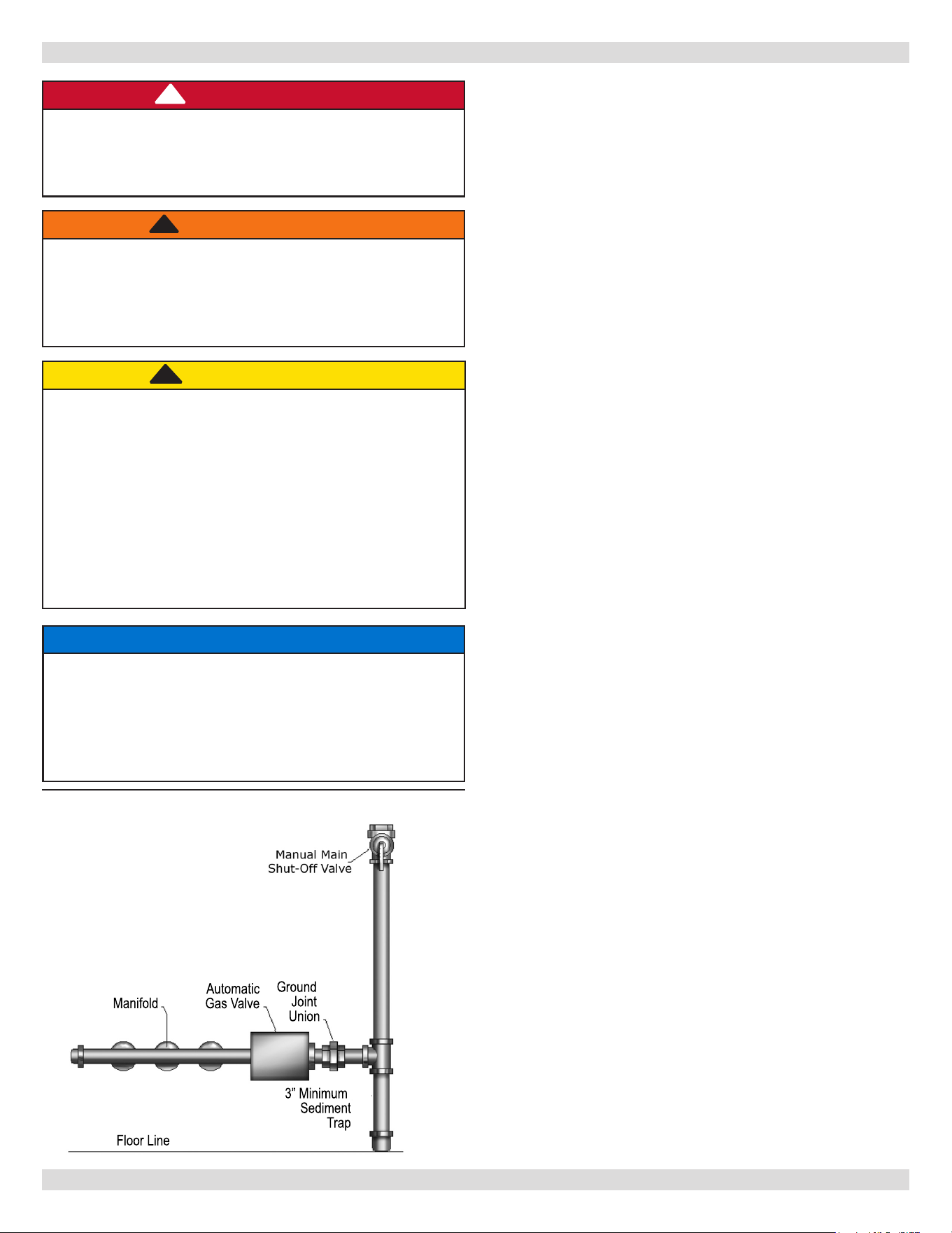
• Install ground joint union in gas supply line between
shut-o valve and boiler controls.
• Install sediment trap upstream of gas controls.
• Use two pipe wrenches when making connection to gas
valve to keep it from turning.
• Install manual shut-o valve in vertical pipe about 5 feet
(1.5 m) above oor. See Figure 10.
• Tighten all joints securely.
• Propane gas connections should only be made by
licensed propane installer.
• Two-stage regulation should be used by propane
installer.
• Propane gas piping should be check by propane installer.
Check Gas Supply
Gas pipe must be correct size for length of run and for
total BTU per hour input of all gas utilization equipment
connected to it. See Gas Table 5 & 6 for proper size. Be
sure your gas line complies with local codes and gas
company requirements.
Check Gas Piping
Pressure test boiler and gas connection before placing
boiler in operation.
• Pressure test over 1/2 psig (3.5 kPa). Disconnect
boiler and its individual gas shuto valve from gas
supply system.
• Pressure test at 1/2 psig (3.5 kPa) or less. Isolate
boiler from gas supply system by closing manual gas
shuto valve. See Figure 10.
• Locate leakage using gas detector, noncorrosive
detection uid, or other leak detection method
acceptable to authority having jurisdiction.
• Correct leaks immediately and retest.
10 - GAS SUPPLY PIPING
Figure 10 - Gas Piping At Boiler
NOTICE
Use of CSA approved corrugated, semi-rigid
stainless steel tubing with polyethylene jacketing
is approved for use with boilers following tubing
manufacturer’s instructions.
Use of exible appliance gas tubing also known as a
“whip” is not allowed per NFPA 54.
3” Minimum
Sediment
Trap
Manifold
Floor Line
Automatic
Gas Valve
Ground
Joint
Union
CAUTION
WHAT TO DO IF YOU SMELL GAS
• Do not try to light any appliance.
• Do not touch any electrical switch; do not use
any phone in your building.
• Immediately call your gas supplier from a
neighbor’s phone. Follow gas supplier’s
instructions.
• If you cannot reach your gas supplier, call the re
department.
!!
DANGER
Fire Hazard. Do not use matches, candles, open
ames, or other methods providing ignition source.
Failure to comply will result in death or serious
injury.
!
WARNING
Fire, explosion, asphyxiation and burn hazard.
Boiler piping and gas connections shall be leak
tested before placing boiler in operation. Failure to
follow these instructions and or improper installation
could result in death or serious injury.
!
10�1 Connecting Gas Piping
PN 240013101 Rev. B [08/08/2023]
23
10 - GAS SUPPLY PIPING
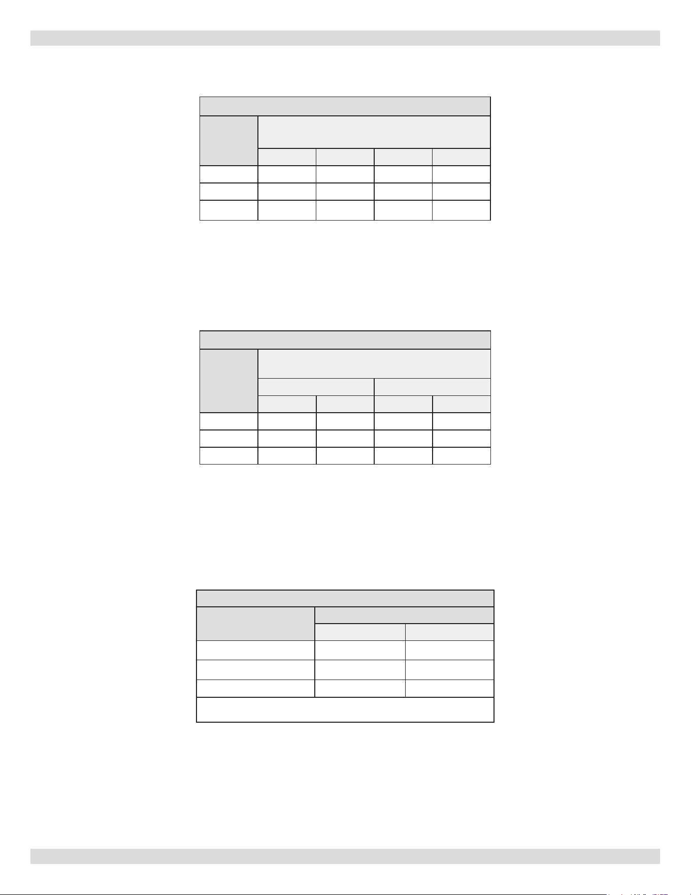
*Outside diameter:
Measure length of pipe or tubing from gas meter or propane
second stage regulator.
Table 5 - NATURAL GAS
Length of
Pipe - Ft�
Pipe Capacity - BTU Per Hour Input
Includes Fittings
½" ¾" 1" 1¼"
20 92,000 190,000 350,000 625,000
40 63,000 130,000 245,000 445,000
60 50,000 105,000 195,000 365,000
Table 7 - Gas Pressure
PRESSURE
GAS
NATURAL PROPANE
MIN� SUPPLY 5" w.c. 11" w.c.
MAX� SUPPLY 13.5" w.c. 13.5" w.c.
MANIFOLD 3.5" w.c. 10" w.c.
Verify minimum pressure while boiler is operating.
Verify maximum pressure when boiler is not operating
Table 6 - PROPANE GAS
Length
of
Pipe - Ft�
Pipe Capacity - BTU Per Hour Input
Includes Fittings
Copper Tubing* Iron Pipe
⅝" ¾" ½" ¾"
20 131,000 216,000 189,000 393,000
40 90,000 145,000 129,000 267,000
60 72,000 121,000 103,000 217,000
PN 240013101 Rev. B [08/08/2023]
24
11 - ELECTRICAL WIRING
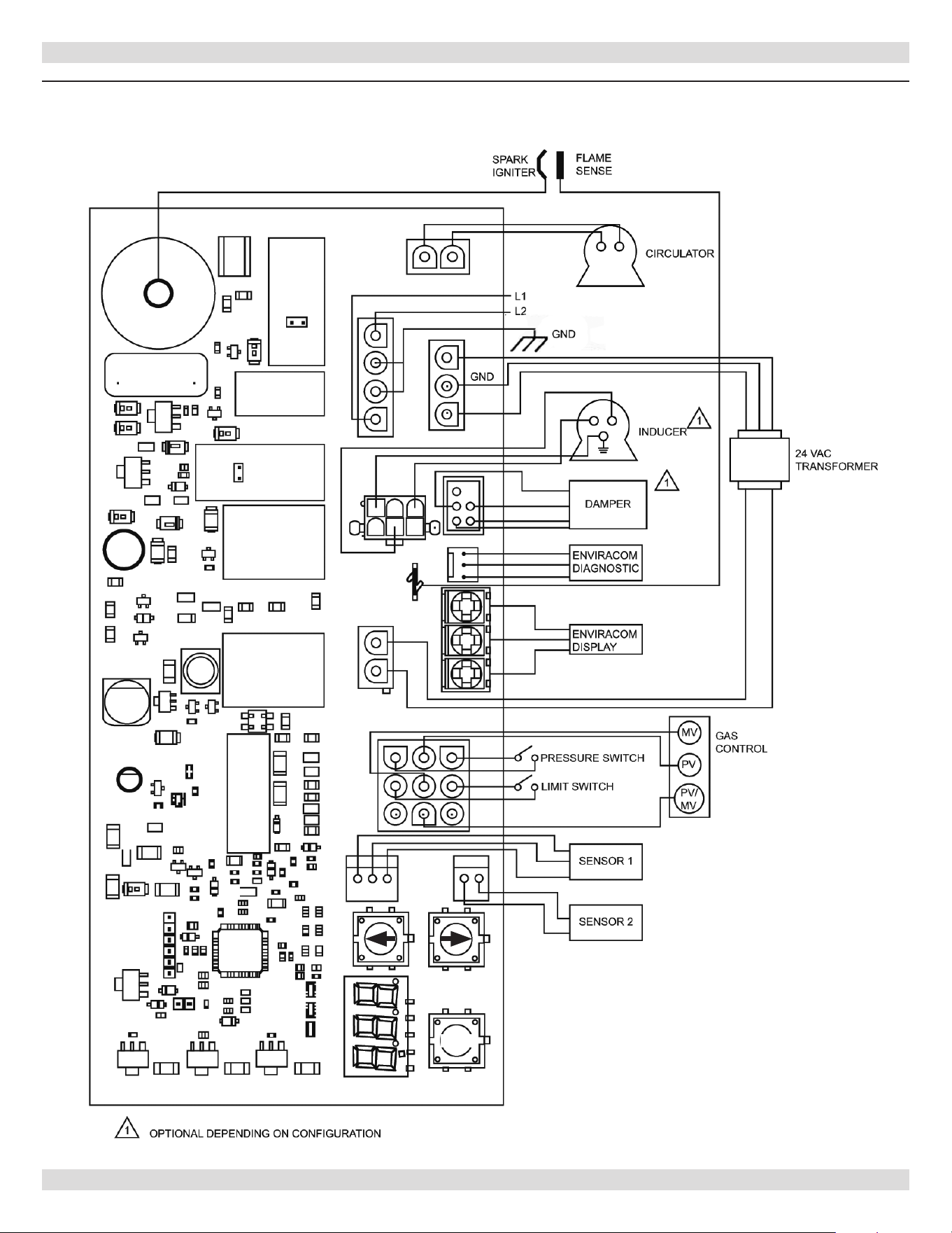
See wiring diagram Figure 12 for details. Refer to
Ladder Diagram from document envelope received
with boiler.
Electrically bond boiler when installed to ground in
accordance with requirements of authority having
jurisdiction or in the absence of such requirements, with
the National Electrical Code, ANSI/NFPA 70
If any of the original wire as supplied with this appliance
must be replaced, it must be replaced with type 105°C
thermoplastic wire or its equivalent
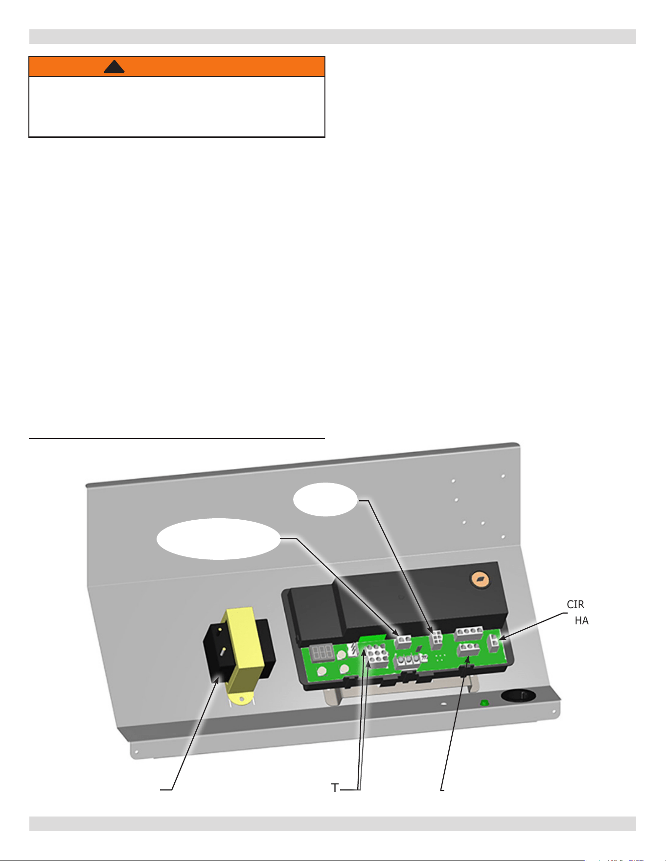
Circulator harness is factory wired to control module.
Connect harness to circulator in eld. See Figure 11.
WARNING
Electrical shock hazard. Turn OFF electrical power
supply at service panel before making electrical
connections. Failure to do so could result in death or
serious injury.
1.
Thermostat should be installed on an inside wall about
four feet above the oor.
2.
NEVER install a thermostat on an outside wall.
3.
Do not install a thermostat where it will be aected
by drafts, hot or cold pipes, sunlight, lighting xtures,
televisions, a replace, or a chimney.
4.
Check thermostat operation by raising and lowering
thermostat setting as required to start and stop the
burners.
5.
Instructions for the nal adjustment of the thermostat
are packaged with the thermostat (adjusting heating
anticipator, calibration, etc.)
6.
Set heat anticipator at .2 amps. 24 volt thermostat
connects to yellow low voltage wires labeled T-T.
Electric Power Supply
Run a separate 115 volt circuit from separate over current
protective device 15 ampere circuit in electrical service
entrance panel.
Refer to parts manual for LWCO kit. When using LWCO
other than kit listed in parts manual follow specic LWCO
THERMOSTAT
WIRES
CIRCULATOR
HARNESS
TRANSFORMER LINE VOLT
BLOWER
TRANSFORMER
SECONDARY
TRANSFORMER
Figure 11 - Control Module Panel
manufacturer instructions.
Connect 115 volt power supply to terminals L1 (HOT) and
L2 inside J box on right side panel.
Run 14 gauge or heavier copper wire from boiler to
grounded connection in service panel or properly driven
and electrically grounded ground rod.
11�1 Electrical Wiring Requirements
11�2 Thermostat Installation
!
PN 240013101 Rev. B [08/08/2023]
25
12 - WIRING DIAGRAM
Figure 12 - Control Module - Wiring Diagram
Damper is not an option.
I
PN 240013101 Rev. B [08/08/2023]

26
1.
Thermostat calls for heat, control relay contacts.
2.
Circulator pump is powered through terminals C1 and
C2. Control holds o burner and attempts to satisfy
thermostat with residual boiler heat.
3.
Induced draft blower is powered.
4.
When blower gets up to speed and blower suction
pressure reaches pressure switch set point, pressure
switch contacts close sending 24 volts to pilot control
from transformer secondary.
5.
Pilot gas valve opens and spark initiates to light pilot
burner.
6.
When pilot ame is proven, spark drops out.
7.
Main gas valve opens and pilot burner ignites main
burners.
8.
If boiler water temperature reaches high limit set
point, high limit contacts open, cutting power to
blower and pilot control. Burners extinguish and blower
stops. Circulator pump continues to run as long as
the thermostat continues to call for heat. When boiler
water temperature drops past the high limit set point
and through the dierential, high limit contacts close,
repeating steps 3-7.
9.
If venting system becomes blocked, blower suction
pressure will drop below pressure switch set point,
opening pressure switch contacts and cutting power to
pilot control. Burners will extinguish, but blower will
remain powered as long as thermostat continues to call
for heat. If venting system clears, steps 4-7 will repeat.
10.
Thermostat is satised, ending call for heat. Relay coil
is de-energized, opening contacts. Burners extinguish.
Blower and circulator pump stop.
13 - SEQUENCE OF OPERATION
13�1 Sequence of Operation
PN 240013101 Rev. B [08/08/2023]

27
• Close air vents on all radiation units. Open valves to
these units.
• Verify boiler and expansion tank drain valves are closed.
Air bleed screw on tank drain tting should be closed.
• Open valve in line from boiler to expansion tank.
• Open water inlet to your boiler and leave open.
• Start with lowest radiation unit. Open air vent on this
unit. When all air has escaped and water starts to ow
from vent, close it.
• Go to next radiation unit, and repeat this process.
• Repeat until you have covered every radiation unit in
system. End at highest unit in system.
• If units have automatic vents, manual venting is
unnecessary but it will speed up proper lling of system.
• If system is closed expansion tank system, you may
have automatic ll valve. Leave it open to rell system
automatically as needed.
• Check temperature-pressure gauge. Note position of
hand indicating pressure. This should be between 10
and 15 psi. Any lowering of this movable hand below
10 psi indicates loss of water due to leakage. Automatic
ll valve should compensate for this. Instructions are
packaged with valve.
14 - STARTING YOUR BOILER
14�1 Filling System
PN 240013101 Rev. B [08/08/2023]
28
1.
STOP! Read Safety Information on previous page.
2.
Set the thermostat to lowest setting.
3.
Turn o all electric power to the appliance.
4.
This appliance is equipped with an ignition device which
automatically lights the burner. Do not attempt to light
pilot by hand.
5.
Remove front panel, if necessary.
6.
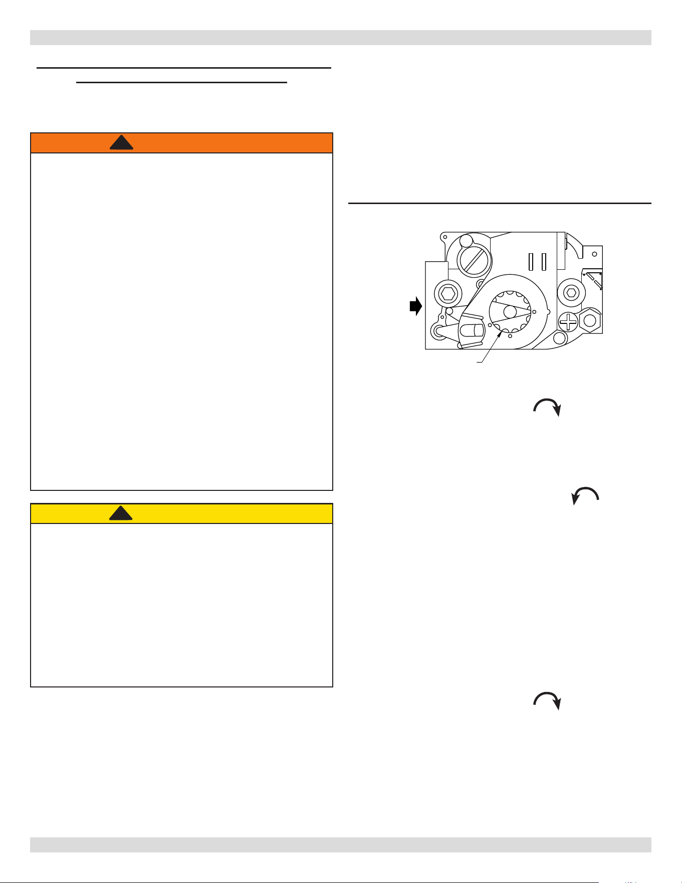
Turn gas control knob clockwise to “OFF”.
7.
Wait ve (5) minutes to clear out any gas. Then smell
for gas, including near oor. If you smell gas, STOP!
Follow WHAT TO DO IF YOU SMELL GAS found on
operating instruction label. If you don’t smell gas, go to
next step.
8.
Turn gas control knob counterclockwise to “ON.”
9.
Replace front panel, if removed.
10.
Turn on all electric power to the appliance.
11.
Set thermostat to desired setting.
12.
If appliance will not operate after several tries, turn gas
control knob to “OFF” and call your service technician
or gas supplier.
1.
Turn o all electric power to the appliance if service is
to be performed.
2.
Set the thermostat to lowest setting.
3.
Remove front panel, if necessary.
4.
Turn gas control knob clockwise to “OFF”. Do not
force.
5.
Replace front jacket panel, if removed.
14 - STARTING YOUR BOILER
OFF
ON
INLET
GAS CONTROL KNOB
SHOWN IN "ON" POSITION
Figure 13 - Gas Control Knob
WARNING
If you do not follow these instructions
exactly, a re or explosion may result
causing property damage, personal injury
or loss of life�
• This appliance is equipped with an ignition
device which automatically lights burner. Do
NOT try to light this burner by hand�
• Before operating smell all around appliance area
for gas. Be sure to smell next to oor because
some gas is heavier than air and will settle to
the oor.
• Use only your hand to turn the gas shuto
valve. Never use tools. If valve will not turn
by hand, do not try to repair it, call a qualied
service technician. Force or attempted repair
may result in re or explosion.
• Do not use this appliance if any part has
been under water. Immediately call a qualied
service technician to inspect appliance and to
replace any part of control system and any gas
control which has been under water.
!
LIGHTING PROCEDURE FOR BOILER WITH
INTERMITTENT PILOT SYSTEM
14�2 Operating Instructions
14�3 Turn Off Gas To Appliance
CAUTION
WHAT TO DO IF YOU SMELL GAS
• Do not try to light any appliance.
• Do not touch any electrical switches; do not use
any phone in your building.
• Immediately call your gas supplier from a
neighbor’s phone. Follow the gas supplier’s
instructions.
• If you cannot reach your gas supplier, call the re
department.
!!
For Your Safety, Read Before Operating!!
PN 240013101 Rev. B [08/08/2023]
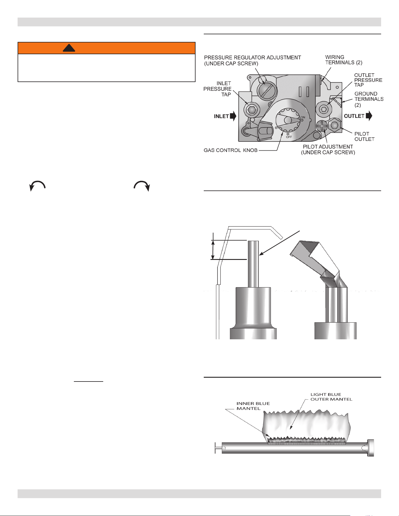
29
Ignition system safety shuto device must be tested after
placing boiler in operation.
With main burners ring, disconnect ignition cable from
intermittent pilot control box. Gas valve should shut o
main burners. TURN OFF ELECTRIC POWER to boiler before
reconnecting ignition cable, to prevent electric shock.
1.
Remove screw cover over pilot adjusting screw.
2.
Insert small screwdriver and adjust ame as needed
See
Figure 14 & 15
. Turn screw counterclockwise
to increase ame, clockwise to decrease.
Replace screw cover over pilot adjusting screw.
Main burners do not require primary air adjustment and are
not equipped with primary air shutters.
Main burner ames form sharp blue inner cones in softer
blue outer mantel, with no yellow. Pus of air from blowing
on ame or stamping on oor will cause ames to turn
orange momentarily. This is not unusual. Remain still when
observing main burner ames. See
Figure 16
.
If ame appearance is not correct, check main burner
orices, burner throat and ame ports for dust and lint
obstruction. It may be necessary to remove rollout shield
to observe main burner ames. Replace rollout shield after
observation.
Instructions for each control are included with the controls.
See Appendix A.3.
Recommended Boiler Water Temperatures
Settings can be changed after you have had some idea how
the system works. Example: If your system does not give
quite enough heat in very cold weather, you can raise limit
setting to 190°F.
Instruction for nal adjustment of thermostat are packaged
with thermostat.
15 - CHECKING AND ADJUSTING
Figure 15 - Pilot Flame Adjustment
3/8” to
1/2”
Flame
Ignition Electrode
15.1 Gas Valve Safety Shutdown Test
15�2 Pilot Burner Adjustment
15�3 Main Burner(s) Inspection
15�4 Adjusting Limit Controls
Figure 14 - Automatic Gas Valve
Figure 16 - Main Burner Adjustment
Main burner ame should form sharp blue inner mantel
with no yellow.
WARNING
Electrical shock hazard. Follow instructions to turn
o electric power. Failure to do so could result in
death or serious injury.
!
PN 240013101 Rev. B [08/08/2023]

30
15 - CHECKING AND ADJUSTING
1.
Set Heat anticipator at .2.
2.
Check thermostat operation. When set above
temperature indicated on thermometer, boiler burners
should ignite. Verify thermostat turns o boiler when
room temperature reaches selected setting and starts
boiler operating when room temperature falls few
degrees. After setting limit control to desired setting,
check to see if it shuts o gas supply to burners.
3.
Turn your thermostat up to call for heat and let your
boiler run until temperature of water reaches limit
setting. Gas valve shuts o and circulator keeps
running until thermostat is satised, or water cools
enough to restart burners through limit control.
4.
To check operation of contacts in pressure switch,
disconnect rubber tubing (located between blower and
pressure switch) from pressure switch, while boiler
is operating. Burners extinguish and blower keeps
running. When tubing is reconnected to pressure
switch, ignition sequence begins, resulting in ignition of
main burners.
5.
Set thermostat for desired temperature.
Safe lighting and other performance criteria were met with
gas manifold and control assembly provided on boiler when
boiler underwent tests specied in ANSI Z21.13.
15�5 Thermostat Heat Anticipator Setting
PN 240013101 Rev. B [08/08/2023]

31
Burners
Beginning of heating season visually check pilot and main
burner ames. See
Figures 15 & 16.
Safety Relief Valve
Test safety relief valve for proper operation. Refer to valve
manufacturer’s instructions packaged with relief valve.
Expansion Tank (Non-diaphragm)
Tank may become waterlogged, or may receive excess
of air. Frequent automatic opening of safety relief
valve indicates water logging. High boiler temperature
accompanied by unusually low radiation unit temperature
(and “knocking”) indicates excess air in tank.
To correct:
1.
Close valve between boiler and tank. Drain tank until
empty.
2.
Check all tank plugs and ttings. Tighten as necessary.
3.
Open valve between boiler and tank. Water will rise to
normal height in tank if you have automatic ll valve
(otherwise, manually rell system).
Boiler Flue Passages
Recommend following checked annually by qualied service
agent.
• ue passages
• burner adjustment
• operation of controls
Before start of each season (or whenever system has been
shut down for some time) recheck whole system for leaks
and recheck boiler and vent pipe for leaks. Replace or patch
any boiler seals that are faulty. Before start of each season
(or whenever system has been shut down for some time)
recheck the whole system for leaks . . . and recheck the
boiler and vent pipe for leaks. Replace or patch any boiler
seals that are faulty.
Vent Pipe
Venting and piping should be checked at least monthly. If
vent piping shows any sign of leaking, replace immediately.
Water System
If system is to remain out of service during freezing
weather, always drain it completely (water left in to freeze
will crack pipes and/or boiler).
Cleaning Your Boiler And Burners
Flue passages between sections should be examined yearly
and cleaned if necessary.
To clean:
• Remove burners, pilot, and vent pipe.
• Remove top and front jacket panels.
• Remove two screws attaching intermediate front panel
to left and right side jacket panels.
• Remove control panel as a unit.
• Remove draft diverter and intermediate front panel.
• Carefully remove cerafelt gasket strips.
• Clean passageways between sections with exible
handle wire brush. Remove dirt from bottom of boiler
and from between sections by vacuuming.
• Verify all ame ports in burners are open and clear.
Shake out or blow out all loose dirt in burners.
• Reseal seams between adjacent sections as necessary
with 400
°
F RTV silicone sealant.
• Reassemble all parts.
• Verify tightness of pilot connections and condition of
burner ames after reassembly. See Figures 15 & 16.
• Verify vent pipe connections to chimney are secure and
no obstructions are present.
Blower
Blower motor features permanently lubricated ball bearing
construction. Lubrication is not required.
Circulator Pump Isolation Valves
Operate isolation valves in circulator pump anges
manually once or twice per year to prevent valves from
becoming stuck in open position
Rotate valves from open position to closed position and
back to open position.
Low Water Cuto(s)
Inspect eld sourced low water cutos annually or
as recommended by low water cuto manufacturer.
Flush oat type low water cuto(s) per manufacturer’s
instructions.
Housekeeping
• Keep boiler area clear and free from combustible
materials, gasoline and other ammable vapors and
liquids.
• Keep boiler area clear of debris and other materials
obstructing ow of combustion and ventilation air.
16 - MAINTAINING YOUR BOILER
16�1 General Maintenance
PN 240013101 Rev. B [08/08/2023]
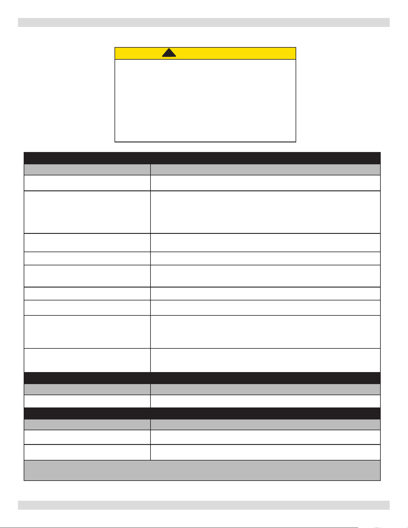
32
You may avoid inconvenience and service calls by checking these points before you call for service:
IF YOUR SYSTEM IS NOT HEATING OR NOT GIVING ENOUGH HEAT . . .
POSSIBLE CAUSE WHAT TO DO
Thermostat is not set correctly Reset thermostat
Burner is not operating properly
Check ame. If it is yellow, the burner is not getting enough air. Or, if
ame is blue and noisy and seems to lift o the burner, the burner is
getting too much air. Contact your service technician.
No electric power to boiler
Check over-current protection. Check to be sure electric power supply
circuit is “ON”.
Controls out of adjustment Reset according to instructions.
Radiators not heating
Open radiator vents to excess air. Check ow control valve (if used). It
may be in closed position.
Circulating pump not running Check over-current protection. Check relay operation.
Poor electrical contact Check all control terminals and wire joints.
Chimney ue is blocked
Pressure switch will not close and pilot spark will not operate to start
pilot. Have your service technician check and correct, if necessary.
Rollout switch blown
Have your service technician check heat exchanger for blockage. Replace
rollout switch with exact replacement.
IF BURNER IS NOISY . . .
POSSIBLE CAUSE WHAT TO DO
Gas input amount is incorrect Contact your service technician.
RELIEF VALVE LEAKING . . .
POSSIBLE CAUSE WHAT TO DO
Dirt on seat Open valve manually. Allow water to run and clear valve seat.
Water logged expansion tank Drain tank, see manufacturer instructions.
HAVE YOUR SERVICE TECHNICIAN CHECK ANY PROBLEM YOU
ARE UNABLE TO CORRECT.
17 - SERVICE HINTS
CAUTION
WHAT TO DO IF YOU SMELL GAS
• Do not try to light any appliance.
• Do not touch any electrical switch; do not use any
phone in your building.
• Immediately call your gas supplier from a neighbor’s
phone. Follow the gas supplier’s instructions.
• If you cannot reach your gas supplier, call the re
department.
!!
PN 240013101 Rev. B [08/08/2023]
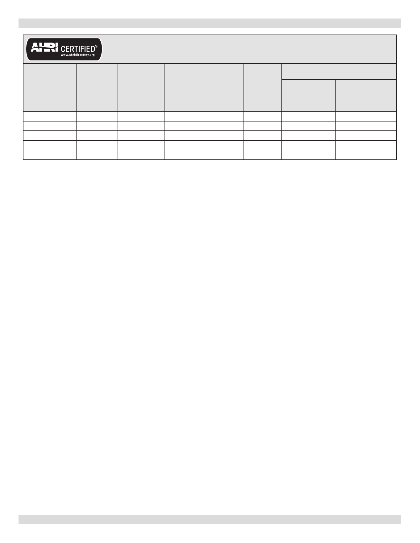
33
18 - BOILER RATINGS & CAPACITIES
(1) Input rating for sea level to 2,000 feet. (610 m) above sea level.
(2) Net AHRI Water Ratings shown
based on piping and pickup allowance of 1.15. Consult Manufacturer before
selecting boiler for installations having unusual piping and pickup requirements, such as intermittent system
operation, extensive piping systems, etc.
For forced hot water systems where boiler and all piping are within area to be heated, boiler may be selected
on basis of its heating capacity.
EXPLANATORY NOTES
• This boiler cannot be used with all types of chimneys. Read these instructions carefully before installing.
• These Gas-Fired Hot Water Boilers are low pressure, sectional cast iron boilers Design Certied by C.S.A. (Canadian
Standards Association) for use with Natural and Propane Gases.
• Constructed and hydrostatically tested for maximum working pressure of 50 psi in accordance with A.S.M.E. Boiler
and Pressure Vessel Code Section IV Standards for cast iron heating boilers.
• Boilers must stand on noncombustible oor. If installed on combustible oor, please refer to (Combustible Floor
Addendum) included in literature envelope provide with boiler and outlined in National Fuel Gas Code, ANSI Z223.1/
NFPA 54.
• The MEA number for this boiler is 484-84-E Vol� IV�
Boilers For Use At High Altitude
Boiler is factory equipped for use at altitudes of 0-2,000 feet above sea level. For use at altitudes above 2,000 feet above
sea level, reduced input rate 4% for every 1,000 feet above sea level.
U�S�A� Only - For altitudes above 2,000 feet above sea level, input ratings should be reduced at rate of 4% for each
1,000 feet above sea level. Consult National Fuel Gas Code (NFPA54/ANSI Z223.1), or manufacturer for correct orice
sizing information. High altitude orices are available from boiler manufacturer.
PN 240013101 Rev. B [08/08/2023]
Table 8 - RATINGS NATURAL AND PROPANE GASES
Model
(1)
Input
Btu/hr
(1)
Heating
Capacity
Btu/hr
(2)
Net
AHRI Rating Water
Btu/hr
AFUE
Vent Diameter (Inches)
To Chimney
(Category I)
Horizontal Vent
(Category III)
FSB-2 42,500 36,000 31,000 84.4 4 3
FSB-3 75,000 63,000 55,000 84.0 4 3
FSB-4 112,500 95,000 83,000 84.0 4 3
FSB-5 150,000 127,000 110,000 84.0 4 3
FSB-6 187,500 158,000 137,000 84.0 4 4
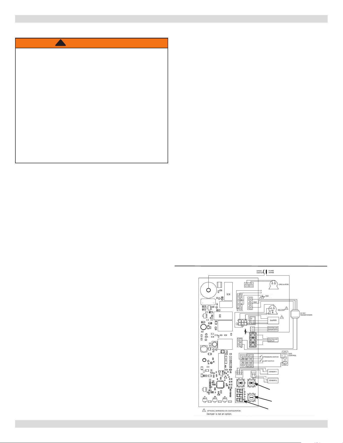
34
APPENDIX A - CONTROL MODULE
• Install plastic cover. Limits contamination from
accumulation of dust or grease.
• Controls can be damaged by excessively high
temperatures. Verify adequate air circulation around
louvers is maintained when installing boiler.
• Connect L1, L2 and ground leads connect inside J box
using wire nuts. Secure J box cover. (J box located
on right side panel.)
• Connect Circulator harness to circulator. Harness
comes plugged into module with Molex
®
plug.
• Connect thermostat connection to yellow wires
marked T-T using wire nuts.
• Ensure remaining Molex
®
plug connectors have not
worked loose during transit.
• Check sensing bulb is fully inserted in well and is not
loose.
• Verify pressure switch connection is made.
To discourage unauthorized changing of settings, procedure
to enter adjustment mode is required.
To enter adjustment mode, press UP, DOWN, and I buttons
simultaneously for three seconds. Press and release I
button until parameter requiring adjustment is displayed.
See Figures A-1 & A-2.
о “SP_” Setpoint (180 °F default setting; adjustable
between 130 and 220 °F). Note: on some models
this is “HL” High Limit�
о “Df_” Setpoint Dierential (15 °F default setting;
adjustable between 10 and 30 °F). Note: on some
models this is “HdF” High Limit�
о “°F_” Degrees Fahrenheit
Press UP or DOWN button until parameter has reached
desired value. After 60 seconds without any button inputs,
control automatically returns to READ mode.
A�4 Display
In RUN mode, status items and parameters are viewable.
See Figure A-3.
Example, to display setpoint, control ashes “sp” (setpoint)
followed by temperature (i.e., 135), followed by °F or °C.
To read settings, press and release I key to nd parameter
of interest.
Example, press and release I until setpoint (sp) is
displayed, followed by three-digit number, i.e., 190,
followed by °F or °C. Press I button again will display
(S1T), Sensor 1 Temperature followed by three-digit
number and corresponding degree designator.
A�1 Installation Environment Considerations
A�2 Electrical Connections
A�3 Adjusting Settings
WARNING
If you do not follow these instructions
exactly, a re or explosion may result
causing property damage, personal injury
or loss of life�
• Do not use this appliance if any part has
been under water. Immediately call a qualied
service technician to inspect appliance and to
replace any part of control system and any gas
control which has been under water.
• Do not allow water to drip on controls. Prevent
condensation by allowing air circulation around
module and gas control.
• Do not use corrosive chemicals around or on
module or gas control.
!
“I” Button
Up & Down Buttons
Display
Figure A-1
- Display
PN 240013101 Rev. B [08/08/2023]
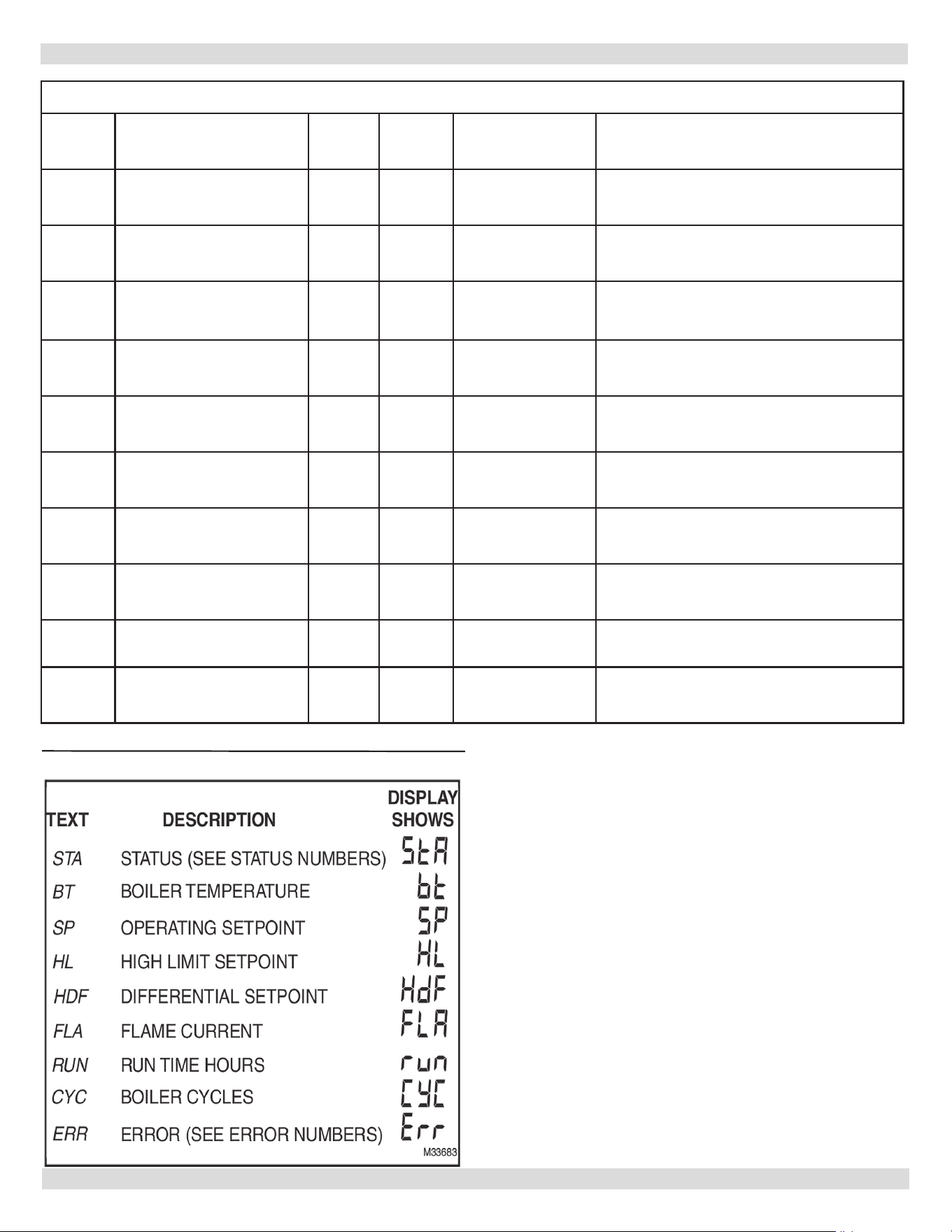
35
APPENDIX A - CONTROL MODULE
Figure A-2 Segment LED Display - Installer Mode Options
1st
Screen
2nd Screen
3rd
Screen
Default Range Description
HL_
<High Limit>
°F or
°C
180 130 to 220 °F
Adjust High Limit setting SP=HL
Note: Also changes SP setpoint
HdF
<High Limit Dierential>
°F or
°C
15 10 to 30 °F
Adjust High Limit Dierential
Or_
<Pump Overrun Time>
SEC
60 0 to 120
Pump Overrun Time
DO NOT CHANGE DEFAULT SETTING
otH
<ODR maximal temp.>
°F or
°C
55 40 to 70°F
Maximal outdoor temperature
(Use With Outdoor Reset)
otL
<ODR minimal Temp>
°F or
°C
0 -40 to 40°F
Minimal outdoor temperature
(Use With Outdoor Reset)
btL
<minimal water temp.>
°F or
°C
140 130 to 150 °F
Minimal boiler temperature
(Use With Outdoor Reset)
tPL
<minimal boiler temp.>
°F or
°C
140
OFF,
120 to 160°F
Thermal purging minimal temperature
DO NOT CHANGE DEFAULT SETTING
tPt
<maximal delay>
Min 2 1 to 10 minutes
Maximal Thermal Purge time
DO NOT CHANGE DEFAULT SETTING
rSt
On or OFF
OFF NA
Reset Lockout
DO NOT CHANGE DEFAULT SETTING
F-C
°F or °C
F F or C
Select degrees F or C Mode
Figure A-3
- Display Readout
PN 240013101 Rev. B [08/08/2023]
36
APPENDIX A - CONTROL MODULE
Module continuously monitors boiler water temperature and
res or shuts o burner based on this temperature data.
1.
When “Call for Heat” occurs, control enables circulator
and monitors boiler water temperature to determine
whether thermostat can be satised without ring
burners. This may delay burner up to two (2) minutes
or less.
Table A-1 - Operation State Codes
Order
State
Code
Number
Denition Explanation
a
1
Idle There is no call for heat; and/or:
b 1
Circulator
The thermostat has called for heat. The control has activated the system circulator
pump and is waiting to see if there is enough heat stored in the boiler to satisfy
the t’stat without ring the burners. This may last as long as 2 minutes, but will
typically be much less.
c
17
Diagnostics Pilot valve diagnostics/current leakage detection. Typically a few seconds.
d
2
Wait for
pressure switch
to open
The inducer motor should be o while the boiler is o to conserve energy. The
control is verifying the motor is indeed o (a switch must be open). If the switch
is not open ERR 2 will be displayed.
e
3
Wait for
pressure switch
to close
The control starts the inducer (vent motor) A pressure switch must close to verify
the motor is running and the vent to outside is not obstructed. If this does not
occur after one minute, the control will go into ERR29. Should the switch eventually
close, the control will resume normal operation.
f
4
Pre-purge
Control is clearing gases out of the heat exchanger. Also, an internal electronic
diagnostic check is performed.
g
6
Spark
Spark for ignition. There should be an audible sparking (buzzing) noise. This will
last until the control detects a pilot ame, but not more than 30 seconds. (If no
ame is detected after trial period, sparking will cease, and a 5 minute delay will
occur before the control tries again. STA10 will be displayed during this period).
h
7
Flame
stabilization
The pilot ame must be strong enough (1 uA) for the control to release the main
burners. This will last up to 10 seconds. (If the ame is still not strong enough
after 10 seconds, the control will shut o the pilot, wait 5 minutes, then try again.
STA10 will be displayed during this 5 minute period).
i
8
Running
Main burners are providing heat. This will continue as long as the thermostat
requires. During this period, the control will monitor the pilot signal, boiler
temperature, damper, and limit switches to assure safe operation.
j
9
Post-Purge Inducer motor is purging gases after heat cycle.
k
1
Post operation
The circulator pumps will continue for a short time to deliver stored heat to the
house before it has a chance to escape during the coming o period.
2� Other possible state codes
j 10
Retry Recycle
Delay
5 minute delay after pilot signal is lost. EITHER:
1. Control failed to detect pilot ame after spark period. Check pilot for
contamination; check ignition wire; check electrical ground; Check pilot ame.
2. Control lost pilot ame signal AFTER main burners were lit. Check for adequate
draft and combustion air. Check gas line for adequate pressure.
2.
Control determines burner operation is required,
module proceeds to start burner (see state codes list)
and heats water in boiler until setpoint temperature is
achieved or thermostat is satised.
3.
Burner is de-activated, ignition module completes
heating cycle, returns to idle and waits for temperature
to drop again.
4.
Circulator remains on during, and throughout “Call for
Heat.”
A�5 Display
PN 240013101 Rev. B [08/08/2023]

37
k
11
Wait for
pressure switch
to open - failed
closed
The inducer is still o, but the pressure switch has not opened at the beginning of
the heat cycle.
An alarm is sent, but no lockout occurs.
l 12
Wait for
pressure switch
to close - failed
open
The inducer is on but the pressure switch has not closed yet at the beginning of the
heat cycle.
An alarm message is sent but no lockout occurs.
m 13
Soft lock out
Soft lockout duration is one hour, may override with manual reset. Appropriate error
code will ash alternately.
n 14
Hard lock out
Requires manual reset. Unacceptable high water temperature (err 65) and onboard
electronics failure (err 18) are the only hard lockouts on this model.
o 15
Wait for limit to
close
One of the safety limits - rollout, or Low water cuto (if one is eld installed on the
24V safety circuit) has been activated. Control will resume normal operation once
limit is reset. Underlying cause why the limit switch opened MUST be investigated.
p 16
Flame out of
sequence
Flame signal sensed before trial for ignition. Appropriate error code displayed.
OR
Flame signal sensed out of sequence during post purge
OR
Flame signal present when not expected. Appropriate error code displayed.
q
17
Diagnostics Onboard self check performed at various points during the operation sequence.
APPENDIX A - CONTROL MODULE
Table A-1 - Operation State Codes - Conti�
Order
State
Code
Number
Denition Explanation
PN 240013101 Rev. B [08/08/2023]
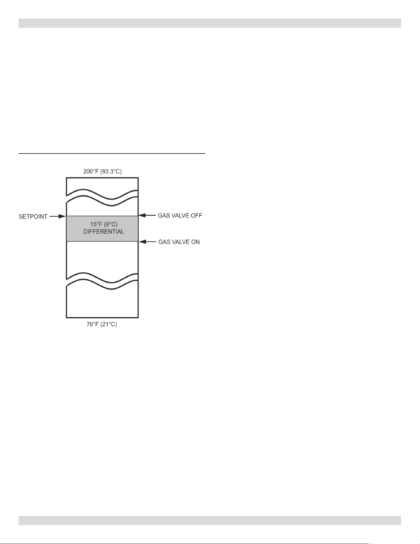
38
APPENDIX A - CONTROL MODULE
• When water temperature reaches setpoint, controller
ends heating cycle.
• When water temperature drops below setpoint minus
dierential, controller restarts heat cycle to re-heat
boiler water.
• If water temperature exceeds maximum allowed
temperature (220°F or 104°C), controller enters manual
reset lockout state.
• For models having reset capability, press any onboard
button or cycle power to reset.
Figure A-4 - Basic Control Algorithm Example
• Following service procedures are provided as general
guide.
• On lockout and retry models, meter readings between
gas control and ignition module must be taken within
trial for ignition period. Once ignition module shuts
o, lockout models must be reset through key buttons
and display. On retry models, wait for retry or reset at
thermostat.
• Check for correct installation and wiring before replacing
any component.
• Control module cannot be repaired. If it malfunctions, it
must be replaced.
• Use only qualied service agent to service ignition
systems.
1.
Perform checkout as rst step in troubleshooting.
2.
Check troubleshooting guide to pinpoint cause of
problem. See Table A-1.
3.
If troubleshooting indicates ignition problem, see
Ignition System Checks to isolate and correct the
problem.
4.
Perform checkout procedure following troubleshooting
guide again to verify system is operating normally.
Integrated boiler control uses advanced diagnostic
capability to assist in troubleshooting error conditions.
Figure A-2 shows codes that could arise on integrated
display during fault.
Suggestions are provided in Table A-2 for servicing these
potential errors.
A�6 Operation A�7 Boiler High Limit Temperature Controller
A�8 Troubleshooting
PN 240013101 Rev. B [08/08/2023]
39
APPENDIX A - CONTROL MODULE
Table A-2 - Operation Error Codes
Error
Code
Error
Description
Error display clearing (once error condition has been corrected)
Clears
itself
when
root
problem
resolved
Cycle
Power
OFF
Push
any key
Up/down
key when
status is
displayed
Explanation Things to look for
2
Pressure switch
failed to open
(stuck closed)
× ×
Control relies on pressure switch to
verify inducer motor is running and
vent is clear. Switch should open
at end of heat cycle, but this did
not occur
1. Check pressure switch
2. Check tubes going to pressure switch, verify no obstruction.
3. Check wiring to pressure switch
4. Remove wire connections to pressure switch. If code persists,
replace control.
4
Flame current
lower then
threshold
× ×
Control requires strong enough
signal 1 (uA) to verify ame is
present. Signal is too low.
1. Check pilot ame sense is clean
2. Check for proper ground
3. Check wiring
4. Check for correct pilot orice
5. Check there are no gas leaks in pilot tubing.
6
Flame sensed
out of normal
sequence
× ×
Control circuit is sensing ame
rectication when there should be
none.
1. Check gas valve
2. Check all electrical connections are tight
18
Electronic failure
× Control believes it is defective.
1. Try reset by cycling power or push any key.
2. Check wiring to pilot and main valve.
3. Otherwise, control will require replacement
23
Flame sensed
during Pre-purge
× ×
Primarily for induced draft models
although present in vent damper
software. Pilot is being sensed too
soon in ignition sequence.
1. Check gas valve - manifold pressure should be 0 when no voltage
to either gas valve circuit.
2. Check all electrical connections are tight
24
Flame sensed
during
Post-purge
× ×
Primarily for induced draft models
although present in vent damper
software. Pilot is being sensed too
late in shutdown sequence.
1. Check gas valve - manifold pressure should be 0 when no voltage
to either gas valve circuit.
2. Check all electrical connections are tight
29
Pressure switch
failed to close
(switch stuck
open)
× ×
Control relies on pressure switch
to verify inducer motor is running
and vent is clear. Switch must close
at start of heat cycle, but this did
not occur
1. Check pressure switch
2. Check venting, verify no obstructions
3. Check tubes going to pressure switch, verify no obstruction.
4. Check wiring to pressure switch
5. Jumper wire connections to pressure switch. If code persists,
replace control. Be sure to remove jumper.
32
Temperature
sensor failure
× ×
Temperature sensor is not providing
an expected reading
1. Check sensor is plugged into control board
2. Check sensor wiring is not damaged
3. Scroll display reading to ""bt"", and hold sensor bulb securely in
your hand. It should read temperature close to body temperature.
If not, replace sensor.
57
Flame rod
shorted to burner
ground
× ×
Control did not detect voltage
dierence between ame sense wire
and ground
1. Check ame sense wire on pilot assembly is not frayed or
otherwise damaged. If so, replace pilot assembly. Note! These are
high temperature wires. Do not attempt eld repair.
2. Check there is not moisture collecting on control board
58
AC line frequency
error
× × AC frequency is incorrect or noisy
1. Some electric or electronic devices may generate electromagnetic
interference. Verify none is present.
2. Check thermostat connection
59
Line voltage error
× ×
Line voltage (or, possibly
thermostat) is either too high or
too low
Source problem is likely in electrical external to boiler. Control
will clear itself and resume normal operation once the situation is
resolved. Check BOTH line power and thermostat wiring.
60
Thermostat input
higher then
threshold
× ×
Certain types of thermostat may not
be compatible with control circuitry
Verify boiler works properly by jumping yellow thermostat wires. If
so, replace thermostat (or possible thermostat wires)
61
Line voltage
unstable
× ×
Unstable line voltage - possibly too
many heavy loads switching on
and o
1. Check if current draw on this branch circuit from house breaker
box might have very heavy loads switching on or o
2. Check power coming into house Source problem is likely in
electrical external to boiler. Control will clear itself and resume
normal operation once situation is resolved.
62
Soft Lockout-Max
retries exceeded
× ×
Control has sensed consecutive
instances of no ame signal while
trying to light pilot.
NOTE: not present on S9361A2095
1. Check control ground connection
2. Check pilot ignition wire for good condition and connection
3. Clean pilot tip
4. Check pilot tube; assure no gas leaks
5. Check correct pilot orice is being used
6. Check gas line pressure
63
Soft Lockout-
Max recycles
exceeded
× ×
Control has sensed consecutive
instances of loss of pilot ame signal
AFTER main burners are lit.
Note: Not present on S9361A2095.
1. Check gas valve
2. Check all electrical connections are tight
3 Check pilot rod is clean
4. Check gas line pressure
5. Check for adequate draft
6. Check for adequate combustion air.
64
Soft Lockout-
Internal Failure
× ×
Control is sensing something wrong
with electrical circuitry
1. Check all wiring is correct. Refer to wiring diagram
2. Check there is good ground to pilot bracket.
65
Hard Lockout-
Temperature
above limit
× ×
Control sensed water temperature
which is too high for safe boiler
operation.
1. Check water is circulating properly through boiler.
2. Check there is not air in system
3. If pressure relief valve opened, there is denitely a problem with
water circulation!
4 If any of the above 3 are true, the root problem is in hot water
circulation.
5. Scroll display reading to ""bt"", and hold sensor bulb securely in
your hand. It should read temperature close to body temperature.
If not, replace sensor.
Note: In event of multiple errors, the highest error number is displayed rst.
Note: Error codes 18 and 65 - Hard Lockout will not expire. Requires operator reset. Nonvolatile memory (error will not be remembered if power is o).
Error codes 6, 23, 62,63 and 64 - Soft Lockout of 1 hour duration if not reset. Control will then resume normal operation. If source error is still
present a second soft lockout it possible.
All other codes - No lockout. Control will resume normal operation immediately when source error is resolved.
PN 240013101 Rev. B [08/08/2023]

40
STEP 3: Check spark ignition circuit.
WARNING
Electrical shock hazard. Ignition circuit generates
over 10,000 volts. Turn OFF electrical power
supply at service panel before making electrical
connections. Failure to do so could result in death
or serious injury.
!
Disconnect ignition cable at SPARK terminal on module.
Energize module and listen for audible sparking noise.
When operating normally, there should be buzzing noise
turns on and o twice per second for duration of 1–7
seconds, depending on model.
Ignition System Checks
STEP 1: Check ignition cable.
• Verify ignition cable does not run in contact with metal
surfaces.
• Verify only factory supplied Ignition cable (or approved
replacement) is used.
• Verify connections to ignition module and igniter or
igniter-sensor are clean and tight.
• Verify ignition cable provides good electrical continuity.
STEP 2:
Verify ignition system grounding. Nuisance shutdowns are
often caused poor or erratic grounding.
Common ground is required for module and pilot burner/
igniter sensor.
— Check for good metal-to-metal contact between
pilot burner bracket and the main burner.
— Check ground lead from GND (BURNER) terminal
on module to pilot burner. Verify connections are
clean and tight. If wire is damaged or deteriorated,
replace with No. 14-18 gauge, moisture-resistant,
thermoplastic insulated wire with 105°C [221°F]
minimum rating.
— Check ceramic ame rod insulator for cracks or
evidence of exposure to extreme heat, which can
permit leakage to ground. Replace pilot burner/igniter
sensor and provide shield if necessary.
— If ame rod or bracket is bent out of position, restore
to correct position.
APPENDIX A - CONTROL MODULE
A�9 Intermittent Pilot
PN 240013101 Rev. B [08/08/2023]
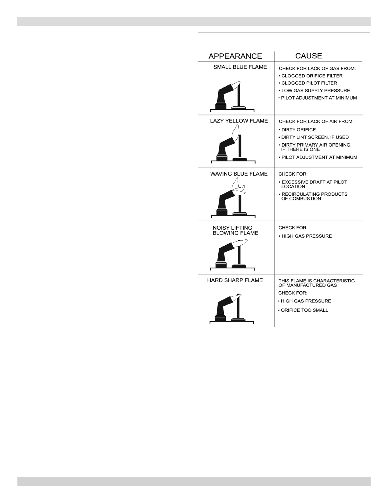
41
APPENDIX A - CONTROL MODULE
STEP 4: Verify pilot and main burner light-o.
1.
Initiate call for heat. Turn thermostat above room
temperature. Ignition sequence may be delayed by
thermal purge until boiler water temperature is below
140°F (60°C)
2.
Watch pilot burner during ignition sequence.
— Verify ignition spark continues after pilot is lit.
— Verify pilot lights and spark stops, verify main
burner does not light.
a. Check pilot ame. Verify it is blue, steady and
envelopes 3/8 to 1/2 in. [10 to 13 mm] of ame rod.
See Figure A-5 for possible ame problems.
b. If necessary, adjust pilot ame by turning pilot
screw on gas control clockwise to decrease or
counter-clockwise to increase pilot ame. Following
adjustment, always replace pilot adjustment cover
screw and tighten rmly to assure proper gas control
operation. See Figure 14.
3.
If pilot does not stay lit, ensure adequate ame current
as follows.
— Turn o boiler at circuit breaker or fuse box.
— Clean ame rod with emery cloth.
— Verify electrical connections are clean and tight.
Replace damaged wire..
— Check for cracked ceramic insulator, which can
cause short to ground, and replace igniter-sensor if
necessary.
Set temperature below room set-point to end call for
heat.
4.
Recheck ignition sequence as follows.
— Adjust thermostat above room temperature.
— Verify ignition sequence at burner.
Figure A-5- Pilot Flame
Correct Pilot Flame: 3/8 to 1/2 inch in ame.
41
PN 240013101 Rev. B [08/08/2023]
42
NOTES
PN 240013101 Rev. B [08/08/2023]
43
INSTALLATION AND CHECK-OUT CERTIFICATE
Boiler Model Serial # Date Installed___________
Measured BTU/HR input____________
Installation instructions have been followed
Checkout procedure and adjustments performed
Maintenance and Service issues reviewed with owner/ maintenance person
Installation booklet axed on or adjacent to boiler
Installer (Company)
Address
Phone
Installer’s Name
Signature
PN 240013101 Rev. B [08/08/2023]

IMPORTANT
In accordance with Section 325 (f) (3) of the Energy Policy and
Conservation Act, this boiler is equipped with a feature that saves energy
by reducing the boiler water temperature as the heating load decreases.
This feature is equipped with an override which is provided primarily to
permit the use of an external energy management system that serves the
same function.
THIS OVERRIDE MUST NOT BE USED UNLESS AT LEAST ONE OF THE
FOLLOWING CONDITIONS IS TRUE:
• An external energy management system is installed that reduces the boiler water
temperature as the heating load decreases.
• This boiler is not used for any space heating
• This boiler is part of a modular or multiple boiler system having a total input of
300,000 BTU/hr or greater.
• This boiler is equipped with a tankless coil.
All specications subject to change without notice.
©2023 ECR International, Inc.
2201 Dwyer Avenue, Utica, NY 13501
Tel.
800 325 5479
www.ecrinternational.com