OIL-FIRED
CAST IRON HOT WATER BOILER
INSTALLATION, OPERATION
& MAINTENANCE MANUAL
Model
3KWC0.80(T)
4KWC1.00(T)
4KWC1.25(T)
5KWC1.35(T)
5KWC1.55(T)
Manufactured by:
ECR International Inc.
2201 Dwyer Avenue, Utica, NY 13501
Tel. 800 325 5479
www.ecrinternational.com
PN 240013445 REV. A [09/01/2021]

2
TABLE OF CONTENTS
Save this manual for reference.
Contents
Boiler Ratings And Capacities ................................3
Safety Notices .....................................................4
Safety Notices .....................................................5
Safe Installation And Operation .............................6
Locating The Boiler ..............................................7
Installation Requirements .....................................8
Fresh Air For Combustion......................................9
System Piping ...................................................11
Antifreeze In The System .................................. 17
Chimney And Chimney Connections .....................17
Electrical Connections ........................................19
Electrical Wiring ................................................20
Filling The Boiler ..............................................21
Operating The Boiler .........................................22
Preliminary Burner Settings ................................23
Checking And Adjusting Controls .........................24
Maintenance .....................................................25
Oil Boiler Cleaning Instructions ...........................26
Service Hints ....................................................27
Pump Curves ....................................................27
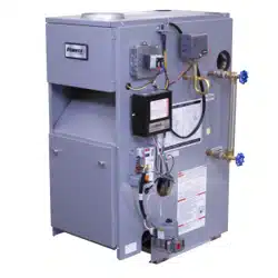
Introduction
Keystone Water boiler is a natural draft oil red hot water
boiler comprised of cast iron sections. Keystone Water
boiler is available with 3, 4, or 5 cast iron sections. These
sections are held together by cast iron push nipples.
Keystone Water boiler is capable of ring #2 fuel oil from
0.80 gph up to 1.55 gph. All packaged boilers include a
swing door, Hydrolevel limit control with built-in low water
cuto, temperature and pressure gauge, safety relief valve,
drain valve, ue brush, and extra boiler tap for expansion
tank or air elimination.
These low pressure oil red hot water boilers are
constructed and hydrostatically tested for maximum
working pressure of 50 psig (pounds per square inch)
in accordance with the latest revision of the A.S.M.E.
(American Society of Mechanical Engineers) Boiler and
Pressure Vessel Code Section IV Standards for heating
boilers.
Heating Capacity indicates amount of heat available after
subtracting losses up the stack. Most of this remaining
heat is available to heat water. A small portion is heat from
the jacket and boiler surface and it is assumed that this
heat stays in the structure. Net AHRI Rating represents
portion of remaining heat that can be applied to heat
radiation or terminal units ( nned tube baseboard, cast
iron radiators, radiant oor, etc.). Dierence between
Heating Capacity and Net AHRI Rating, called piping and
pickup allowance, establishes reserve for heating volume
of water in the system and o-setting heat losses from
system piping. Net AHRI Rating of the boiler selected
should be greater than or equal to calculated peak heating
load (heat loss) for building or area(s) served by the
boiler and associated hot water heating systems. Consult
manufacturer before selecting boiler for installations having
unusual piping and pickup requirements.
These boilers operate on #2 Heating Oil.
For Parts lists see manual 240013446 included with your boiler literature package.
PN 240013445, Rev. A [09/01/2021]
3
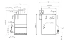
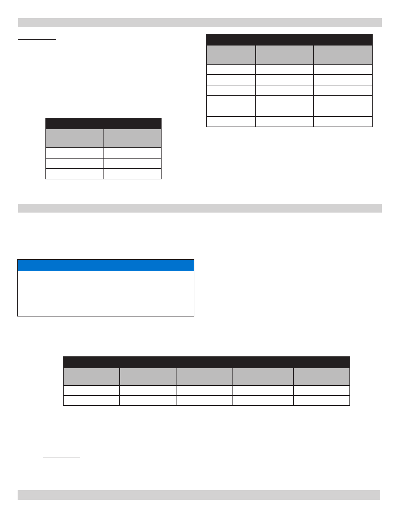
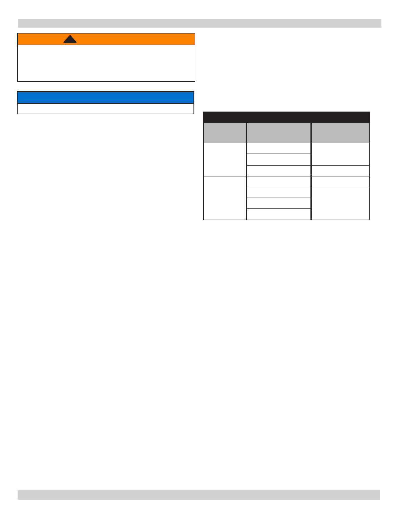
BOILER RATINGS AND CAPACITIES
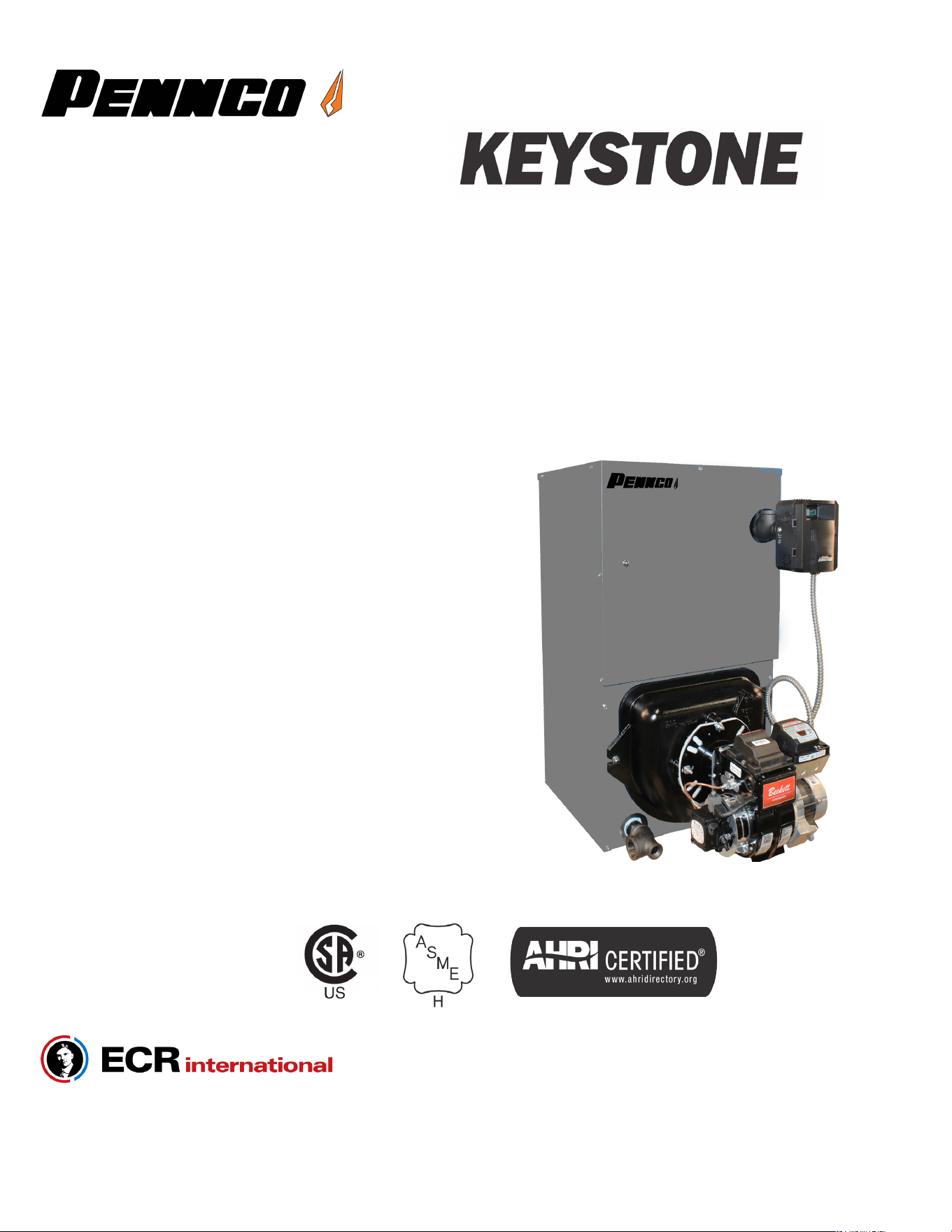
Boiler Ratings and Capacities
Figure 1 - Dimensions
13 3/4”
PN 240013445, Rev. A [09/01/2021]
OIL-FIRED HOT WATER BOILERS
RATINGS & CAPACITIES
BOILER
MODEL
No.
of
Sections
Firing
Rate
†GPH
Input
**MBH
***
Heating
Capacity
**MBH
Net
AHRI
Rating
**MBH
Minimum
Chimney
Size/Height
A.F.U.E.
††
Dimensions (Inches)
A B C
3KWC0.80(T) 3 0.80 112 98 85 8”x8”x15’ 86.0
14½ 6 8
4KWC1.00(T) 4 1.00 140 122 106 8”x8”x15’ 86.2
17¾ 6 9⅝
4KWC1.25(T) 4 1.25 175 152 132 8”x8”x15’ 86.0
17¾ 6 9⅝
5KWC1.35(T) 5 1.35 189 167 145 8”x8”x15’ 86.0
21 6 11½
5KWC1.55(T) 5 1.55 217 189 164 8”x8”x15’ 86.0
21 6 11½
** MBH = 1,000 Btu Per Hour BTU = British Thermal Unit
*** Heating capacity based on 13.1% CO2 with -0.02” W.C. draft over re, and #1 smoke or less. Testing was done in
accordance with D.O.E. (Department Of Energy) test procedure.
† GPH = Gallons Per Hour Of Oil At 140,000 Btu Per Gallon
†† A.F.U.E. = Annual fuel utilization eciency based upon D.O.E. Test procedure.
Net AHRI Water Ratings based on piping allowance of 1.15. Consult manufacturer before selecting a boiler for installations
having unusual piping and pickup requirements, such as intermittent system operation, extensive piping systems, etc.
4
SAFETY NOTICES
CAUTION
Indicates a hazardous situation which, if not
avoided, could result in minor or moderate injury.
!!
WARNING
Indicates a hazardous situation which, if not
avoided, could result in death or serious injury.
!
DANGER
Indicates a hazardous situation which, if not
avoided, WILL result in death or serious injury.
!
This is the safety alert symbol. Symbol alerts you
to potential personal injury hazards. Obey all safety
messages following this symbol to avoid possible injury
or death.
Become familiar with symbols identifying potential hazards.
Boiler installation shall be completed by qualied agency.
WARNING
Do not tamper with or use this boiler for any
purpose other than its intended use. Failure to follow
these instructions could result in death or serious
injury. Use only manufacturer recommended parts
and accessories.
!
NOTICE
Used to address practices not related to personal
injury.
WARNING
Fire, explosion, asphyxiation and electrical shock
hazard. Improper installation could result in death
or serious injury. Read this manual and understand
all requirements before beginning installation.
!
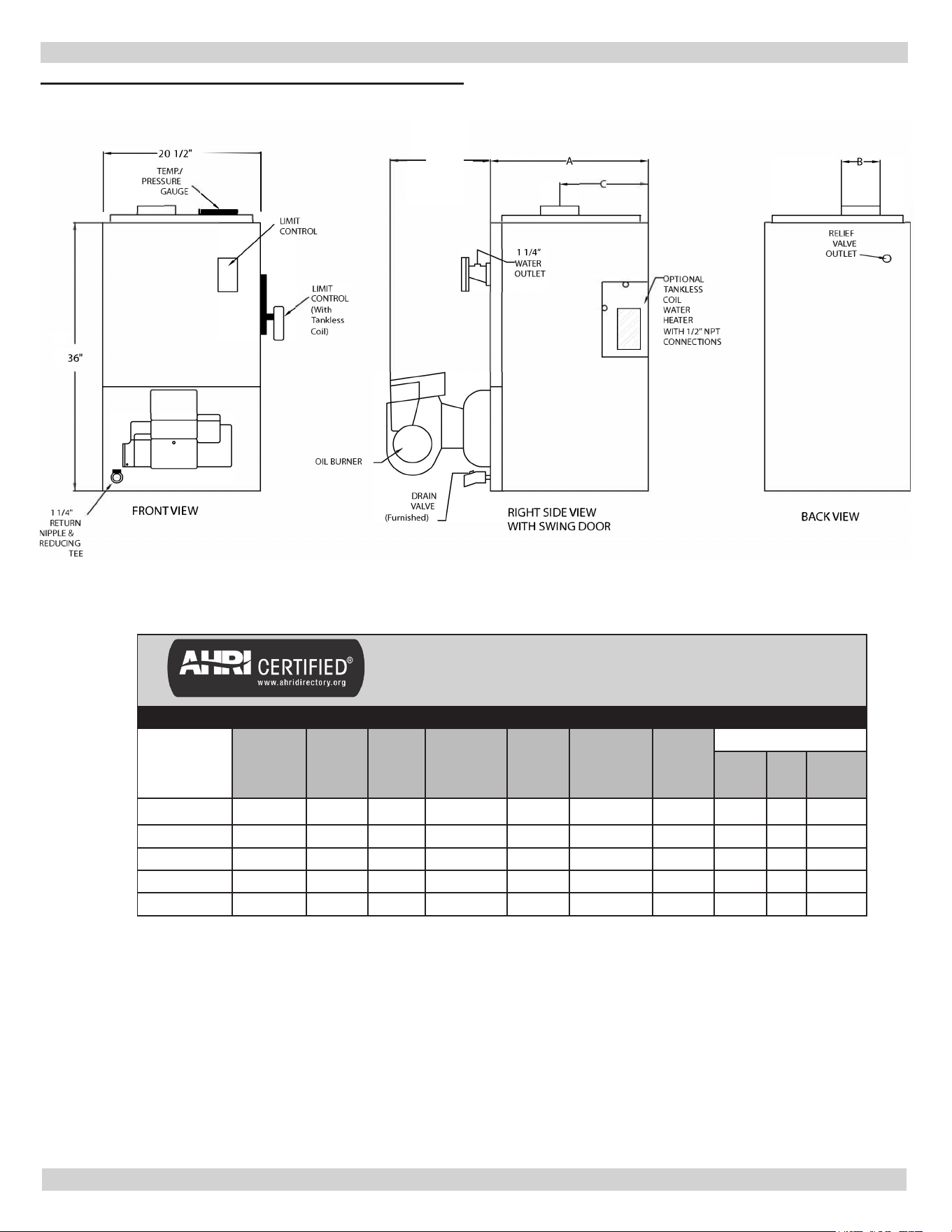
FOR YOUR SAFETY READ BEFORE OPERATING
Hot Water Can Scald!
Water heated to temperature for clothes washing,
dish washing and other sanitizing needs can scald and
cause permanent injury.
Children, elderly, and inrm or physically handicapped
persons are more likely to be permanently injured by
hot water. Never leave them unattended in bathtub or
shower. Never allow small children to use a hot water
tap or draw their own bath.
If anyone using hot water in the building ts the above
description, or if state laws or local codes require
certain water temperatures at hot water taps, you
must take special precautions:
• Use lowest possible temperature setting.
• Install some type of tempering device, such as
an automatic mixing valve, at hot water tap or
water heater. Automatic mixing valve must be
selected and installed according to manufacturer's
recommendations and instructions.
• Water passing out of drain valves may be
extremely hot. To avoid injury:
• Make sure all connections are tight.
• Direct water ow away from any person.
DANGER
!
Water
Temperature
Seng
1st Degree Burn
Exposure Time For
An Adult
2nd and 3rd Degree Burn
Exposure Time For An
Adult
120° F 1 minute 5 minutes
130° F 5 seconds 30 seconds
140° F 2 seconds 5 seconds
150° F 1 second 1.5 seconds
160° F Instantaneous 0.5 seconds
Note: Warning for Infants, Children, and Elderly:
Great care must be taken when exposing the
aforementioned groups to warm or hot water as they
can be badly burned in exposure times less than half
of the time for an adult.
WARNING
Fire, Explosion, Asphyxiation, Electrical shock
hazard! Flooding will result in damages such as
electrical problems, corrosion, inoperative parts,
mold and other unforeseen issues which can
occur over time. Any equipment determined by
a professional as damaged by a ood, dened as
excess of water or other liquid, shall be replaced.
Failure to follow these directions will result in a
Hazardous Situation.
!
PN 240013445, Rev. A [09/01/2021]
5
CAUTION
Laceration, burn hazard. Metal edges and parts
may have sharp edges and/or may be hot. Use
appropriate personal protection equipment to
include safety glasses and gloves when installing
or servicing this boiler. Failure to follow these
instructions could result in minor or moderate injury.
!!
WARNING
Combustion chamber insulation in this product
contains ceramic ber material. Ceramic bers can
be converted to cristobalite in very high temperature
applications. The International Agency for Research
on Cancer (IARC) has concluded, Crystalline silica
inhaled in the form of quartz or cristobalite from
occupational sources is carcinogenic to humans
(Group1). Avoid breathing dust and contact
with skin and eyes. Use NIOSH certied dust
respirator (N95). This type of respirator is based
on the OSHA requirements for cristobalite at the
time this document was written. Other types of
respirators may be needed depending on the job
site conditions. Current NIOSH recommendations
can be found on the NIOSH website
https://
www.cdc.gov/niosh/topics/silica/.
approved
respirators, manufacturers, and phone numbers are
also listed on this website. Wear long-sleeved, loose
tting clothing, gloves, and eye protection. Apply
enough water to the combustion chamber lining to
prevent dust. Wash potentially contaminated clothes
separately from other clothing. Rinse clothes washer
thoroughly.
NIOSH stated First Aid. Eye: Irrigate immediately.
Breathing: Fresh air.
!
SAFETY NOTICES
WARNING
This prod
uct contains Fibrous glass. Fibrous
glass is a synthetic ber made from tiny particles
of glass. Fibrous glass has been classied as a
possible human carcinogen. When disturbed as a
result of servicing or repair, brous glass becomes
airborne and, if inhaled, may be hazardous to
your health. It can harm the eyes, skin, and the
lungs. Airborne bers from these materials have
been listed by the State of California as a possible
cause of cancer through inhalation. Adhere
to the following precautions and procedures.
Avoid breathing dust and contact with skin and
eyes. Use NIOSH certied dust respirator (e.g.,
N95). Other types of respirators may be needed
depending on the job site conditions. Current NIOSH
recommendations can be found on the NIOSH
website https://www.cdc.gov/niosh/. Approved
respirators, manufacturers, and phone numbers
are also listed on this website. Wear appropriate
personal protective clothing to prevent skin contact,
as well as gloves and eye protection. Wash skin
daily at end of each work shift, and prior to eating,
drinking, smoking, etc. Workers whose clothing
may have been contaminated should change into
uncontaminated clothing before leaving the work
premises. Wash potentially contaminated clothes
separately from other clothing. Rinse clothes washer
thoroughly. Follow all Local, State and Federal
guidelines for disposal.
NIOSH stated First Aid. Eye: Irrigate immediately.
Breathing: Fresh air.
!
PN 240013445, Rev. A [09/01/2021]
6
1.
Check your local codes and utility requirements before
installation. Installation shall be in accordance with
their directives, or follow NFPA 31 Installation of Oil
Burning Equipment, latest revision.
2.
Before servicing, allow boiler to cool. Shut o any
electricity and oil to boiler when working on it.
3.
Inspect oil line and connections for leaks.
4.
Verify oil burner nozzle is the size required. Over-ring
will result in early failure of boiler sections. This will
cause dangerous operation.
5.
Never vent this boiler into enclosed space. Always vent
to outside. Never vent to another room or inside a
building.
6.
Verify there is adequate air supply for complete
combustion.
7.
Follow regular service and maintenance schedule for
ecient, safe and reliable operation.
8.
Keep boiler area clean and free of combustible
material, gasoline and other ammable vapors and
liquids.
9.
Oil burners are not do-it-yourself items. Boiler must be
installed and serviced by qualied professionals using
combustion test instruments.
WARNING
Burn and scald hazard. Safety relief valve could
discharge steam or hot water during operation.
Install discharge piping per these instructions.
!
10.
Be aware when piping safety relief valve if system
pressure exceeds safe limit of 30 pounds per square
inch, safety relief valve will automatically lift open.
Lifting of safety relief valve can discharge large
quantities of steam and hot water, which may damage
surroundings. Before installing safety relief valve read
manufacturer’s instructions and maintenance section of
manual on safety relief valves.
11.
Installation and sizing of the expansion tank must
consider heating systems total water volume,
temperature, boiler initial ll pressure, and system
arrangement. Improperly installed and sized expansion
tank may result in frequent lifting of safety relief
valve or other heating system problems. For proper
installation, sizing, and maintenance of expansion tank
follow guidelines established by boiler manufacturer
and expansion tank manufacturer.
12.
Expansion tank performance and life expectancy can be
hindered by overlling the boiler. Boiler manufacturer
recommends initial ll pressure of 10-12 psig. For
higher ll pressures expansion tank’s air charge will
need to be increased to match ll pressure. Consult
manufacturer’s guidelines for sizing and selection.
13.
Purging heating system of air and gases when
rst placing boiler into service is critical for proper
circulation and quiet performance. Once air and gases
are purged, for boiler installations using oat type
vents, air vents should be closed for normal operation.
If air is heard or noticed by loss of heat, purge system
and open vents for short period of time.
SAFE INSTALLATION AND OPERATION
NOTICE
This boiler has been designed for residential
installations. If used for commercial applications,
all jurisdictional requirements shall be met. This
may require wiring and/or piping modications.
Manufacturer is not responsible for any changes to
the original design.
WARNING
Fire, Explosion, burn, scald hazard. Use only number
2 fuel oil. Do not use gasoline, kerosene, crankcase
oil or any oil containing gasoline. Failure to follow
these instructions could result in death or serious
injury.
!
PN 240013445, Rev. A [09/01/2021]
7
Complete Prior To Installing Boiler.
A. Verify you have selected the right size boiler with
proper capacity. AHRI rating of boiler selected
should be greater than or equal to calculated peak
heating load (heat loss) for building or area(s)
served by boiler and associated hot water heating
systems. See boiler rating and capacity table
previously listed in this manual. Any heat loss
calculations used should be based on approved
methods.
B. Boiler must be supplied with proper oil supply
and oil piping, sucient fresh combustion air, and
suitable electrical supply.
C. Boiler must be connected to suitable venting
system and piping system adequate to distribute
heating load.
D. Properly locate and install thermostat for heating
system control.
Any doubts as to requirements, check with local authorities
and obtain professional help where needed. OPERATING
INSTRUCTIONS, FINAL CHECKS AND ADJUSTMENTS, and
MAINTENANCE sections in this manual are vital to the
proper and safe operation of the heating system.
1.
Place boiler in location centralized with piping system and
as close to chimney as possible.
2.
Boiler must be level. If necessary use metal shims
beneath boiler’s feet.
3.
Use raised base if oor can become wet or damp.
4.
Maintain clearances for re safety as well as servicing.
Maintain 18” clearance at a side where passage is
required for access to another side for cleaning,
servicing, inspection, or replacement of any parts that
normally may require such attention. Boilers must be
installed at least 6” from combustible material on left
side, rear and above, and at least 24” on right side
and front. Allow 24” accessibility clearance above for
servicing.
5.
Fresh air for combustion must be available at front of
the boiler. Fresh air for ventilation must be available to
front and rear of boiler. Air passages must be free of
obstructions at all times. Ventilating and combustion
air must enter boiler room without restrictions.
WARNING
Fire hazard. Do not install boiler directly on
combustible ooring or carpeting. Failure to follow
these instructions could result in death or serious
injury.
!
6.
Floor supporting boiler must be noncombustible
and stable. Boiler is permitted to be placed over
combustible oor provided the oor is protected in
accordance with the requirements of accepted building
code practice and approved by the Authority Having
Jurisdiction. In absence of local codes, follow NFPA-31
Standard for the Installation of Oil-Burning Equipment.
7.
Installation shall be in accordance with the
requirements of the authority having jurisdiction.
Compliance with these regulations is required. In the
absence of local codes, follow NFPA 31 Installation of
Oil Burning Equipment, latest
revision.
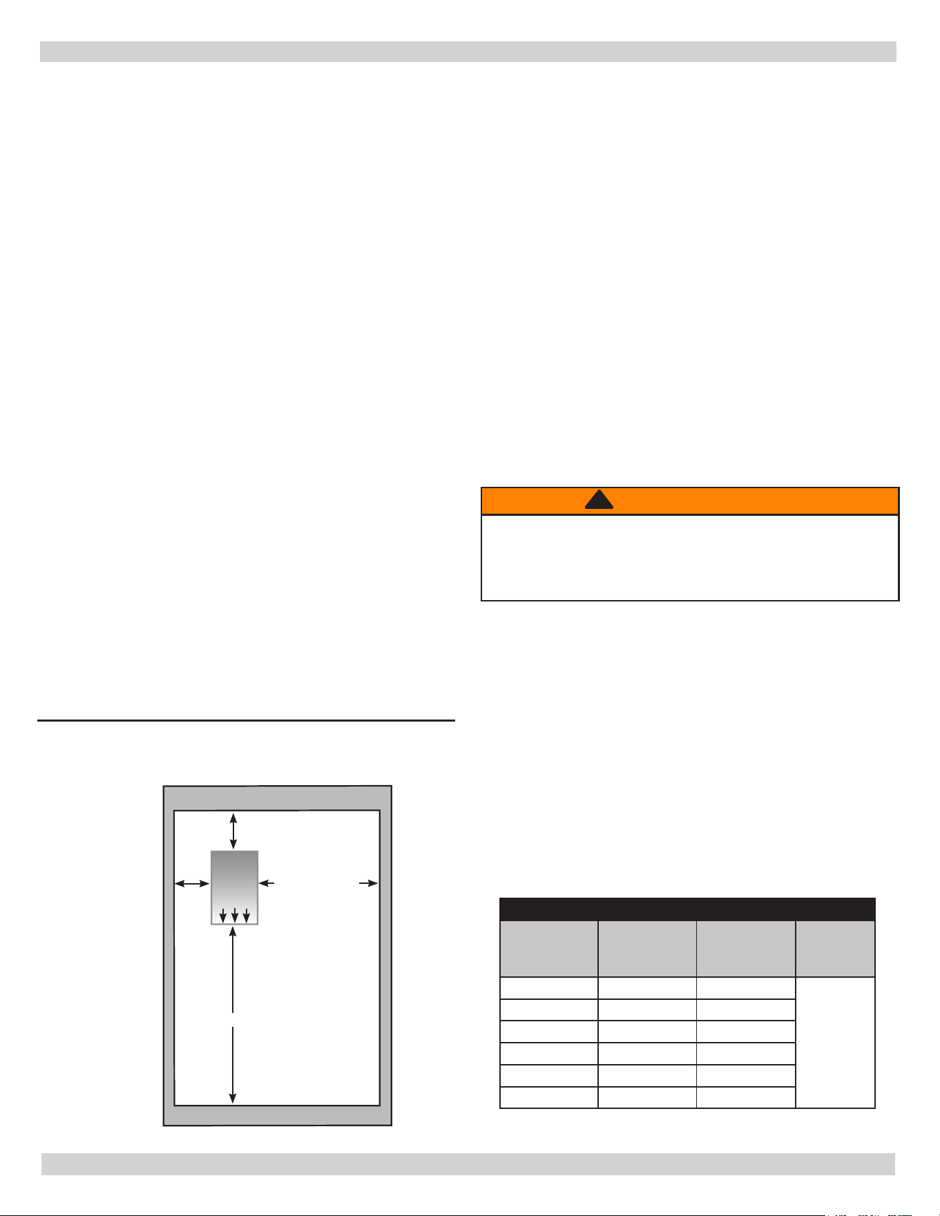
BOILER CLEARANCES
Unit
Combustible
Clearance
Accessibility,
Cleaning, and
Servicing
Flue to
Combustible
Clearance
Top 6” 24”
9”
Right Side 24” 24”
Left Side 6” 6”
Base Non-combustible Non-combustible
Front 24” 24”
Back 6” 6”
All distances measured from the cabinet of the boiler.
24” Min.
6”
Min.
6”
Min.
24”
Min.
Boiler
Front
MINIMUM CLEARANCE DIMENSIONS
LOCATING THE BOILER
Figure 2 - Clearances
PN 240013445, Rev. A [09/01/2021]
8
ALWAYS KEEP MANUAL FUEL SUPPLY VALVE SHUT OFF IF
BURNER IS SHUT DOWN FOR EXTENDED PERIOD OF TIME.
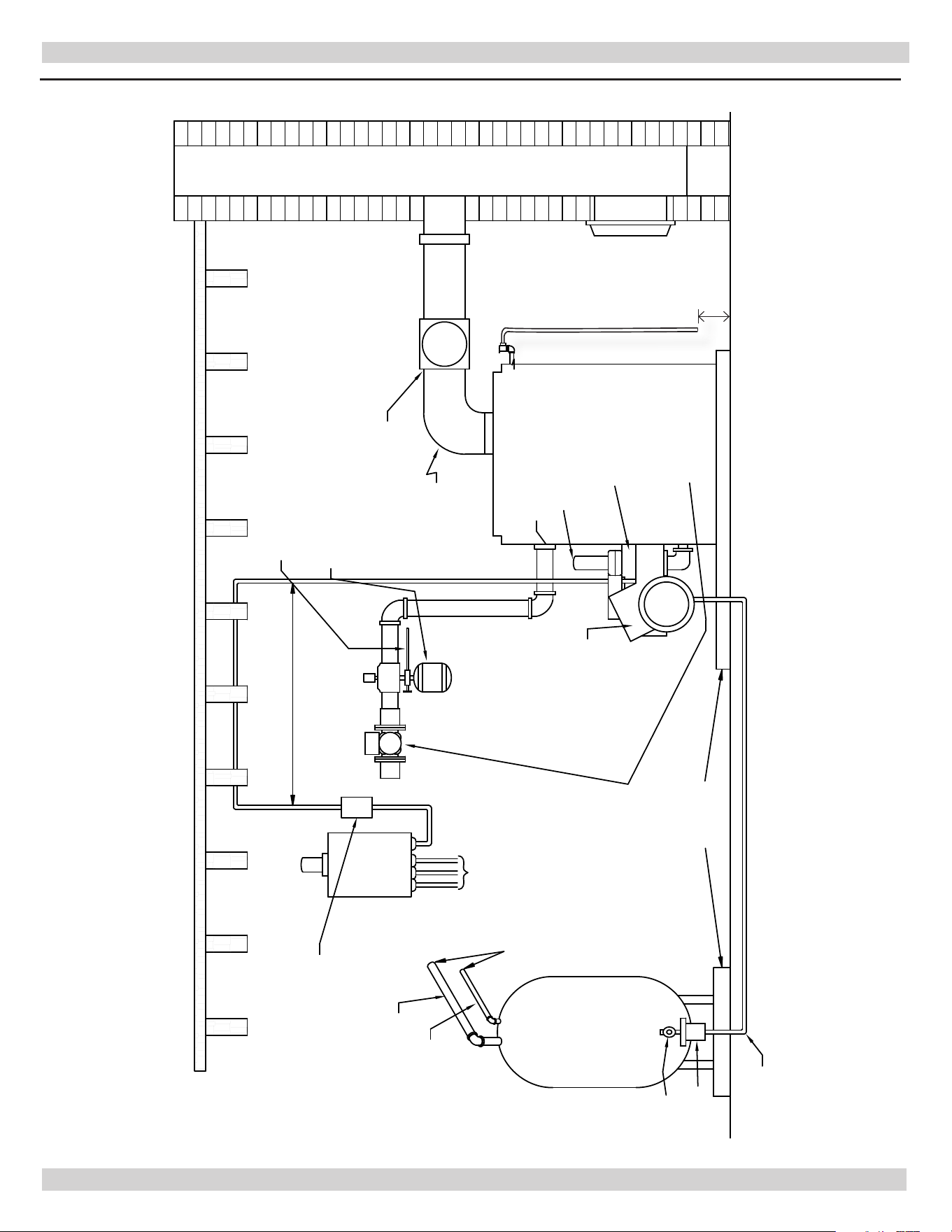
INSTALLATION REQUIREMENTS
Figure 3 - Boiler With Piping System
OIL TANK
C
H
I
M
N
E
Y
ELECTRIC LINE
VENT
PIPE
DRAFT
REGULATOR
DIAPHRAGM
EXPANSION TANK
AUTOMATIC
FILL VALVE
AND SHUTOFF
RELIEF VALVE
TO RADIATION
FROM RADIATION
CIRCULATING
PUMP IN
RETURN LINE
OR AFTER THE
EXPANSION
TANK
SHUT OFF
VALVE
OIL FILTER
OIL LINES
FOUNDATIONS
TO OUTSIDE
LINES TO OTHER
APPLIANCES
SERVICE LINE
OVERCURRENT
PROTECTED
SAFETY SWITCH
2" FILL
PIPE
MIN. 2" I.D.
VENT PIPE
ENTRANCE
SWITCH
OIL BURNER
GENERAL PRINCIPAL REQUIREMENTS FOR A TYPICAL INSTALLATION
within 6” to
the oor
PN 240013445, Rev. A [09/01/2021]
9
Installation shall comply with NFPA-31 Standard for the
Installation of Oil Burning Equipment (latest edition), and
applicable provisions of local building codes to provide
combustion and ventilation air.
Provide enough fresh air to assure proper combustion. Fire
in the boiler uses oxygen. It must have continuous supply.
Air in the house contains only enough oxygen to supply
burner for short time. Outside air must enter house to
replace air used by the burner. Study following examples 1
and 2 to determine your fresh air requirements.
EXAMPLE 1: Boiler Located in Unconned Space
If your boiler is in open area (non partitioned basement) in
conventional house, air that leaks through cracks around
doors and windows will usually be adequate to provide air
for combustion. Doors should not t tightly. Do not caulk
cracks around windows.
Unconned space is dened as space whose volume is not
less than 50 cubic feet per 1,000 Btu per hour of total input
rating of all appliances installed in that space.
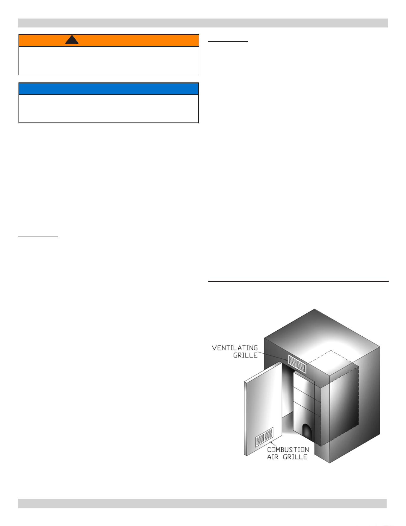
EXAMPLE 2: Boiler Located in Conned Space
A. All Air from Inside the Building: Conned space
shall be provided with two permanent openings
communicating directly with additional room(s) of
sucient volume so that combined volume of all spaces
meets criteria for unconned space. Total input of all
combustion equipment installed in combined space
shall be considered in making this determination. Each
opening shall have minimum free area of one square
inch per 1,000 Btu per hour of total input rating of all
combustion equipment in conned space, but not less
than 100 square inches. One opening shall be within 12
inches of top and one within 12 inches of bottom of the
enclosure.
Example: Your boiler is rated at 100,000 Btu per hour.
Water heater is rated at 30,000 Btu per hour. Total
is 130,000 Btu per hour. You need two grilles, each
with 130 square inches of FREE opening. Metal grilles
have about 60% FREE opening. To nd louvered area
needed, multiply free opening required by 1.7 (130 x
1.7 = 221.0 sq. in. louvered area). In this example,
two grilles each having 8” x 30” (240 sq. in.) louvered
area would be used.
FRESH AIR FOR COMBUSTION
WARNING
Asphyxiation, re hazard. Do not obstruct air
openings to combustion area. Follow instructions
below, to maintain adequate combustion air.
!
NOTICE
Install outside air intake if you use replace or
kitchen or bathroom exhaust fan. These devices rob
boiler and water heater of combustion air.
Figure 4 - Air Openings For Boiler Located In
Conned Space (Utility Room)
PN 240013445, Rev. A [09/01/2021]
10
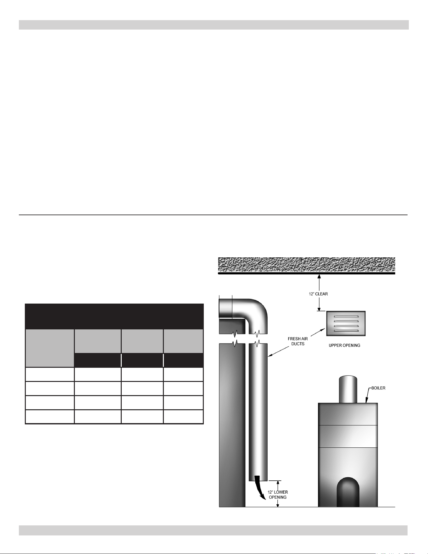
B. All Air from Outdoors: Conned space shall
be provided with two permanent openings,
one commencing within 12 inches of top and
another commencing within 12 inches of bottom
of enclosure. Openings shall communicate
directly, or by ducts, with outdoors or spaces
(crawl or attic) that freely communicate with
outdoors.
1.
When directly communicating with outdoors, each
opening shall have minimum free area of one
square inch per 4,000 Btu per hour of total input
rating of all equipment in the enclosure.
2.
When communicating with the outdoors through
vertical ducts, each opening shall have a minimum
free area of one square inch per 4,000 Btu per
hour of total input rating of all equipment in the
enclosure.
3.
When communicating with outdoors through
horizontal ducts, each opening shall have
minimum free area of one square inch per 2,000
Btu per hour of total input rating of all equipment
in the enclosure.
4.
When ducts are used, they shall be of same cross
sectional area as free area of openings to which
they connect. Minimum dimension of rectangular
air ducts shall be not less than three inches.
FRESH AIR DUCT CAPACITIES
THROUGH LOUVERS
Fresh Air
Duct Size
¼” Mesh
Screen
Wood
Louvers
Metal
Louvers
(Btuh)* (Btuh)* (Btuh)*
3 ½” x 12” 144,000 36,000 108,000
8” x 8” 256,000 64,000 192,000
8” x 12” 384,000 96,000 288,000
8” x 16” 512,000 128,000 384,000
*Btuh = British Thermal Units per hour based on
opening covered by ¼” mesh screen , wood louvers,
or metal louvers.
FRESH AIR FOR COMBUSTION
Figure 5 - Fresh Air Duct Capacities For Ducts Supplying Fresh Air To Boiler In
Tightly Constructed Houses
PN 240013445, Rev. A [09/01/2021]
11
1.
Installation of boiler for new heating system,
Install all of radiation units (panels, radiators,
baseboard, or tubing) and supply and return mains
rst. After all heating system piping and components
have been installed, make nal connection of system
piping to boiler. It is recommended to mount circulating
pump on supply side piping, such that it pumps away
from expansion tank. Refer to gures on next pages.
2.
Equip hot water boiler installed above radiation
level with low water cut o device. Periodic inspection
is necessary, as is ushing of oat type devices, per low
water cut o manufacturer’s specic instructions.
3.
Packaged boiler is set up with 1¼” NPT supply
and return piping from front of boiler. Boiler supply
and return piping can be moved to rear of boiler. Boiler
should not be piped return line to front, supply line
to rear, or vice versa, will cause boiler water to short
circuit heat exchanger. Piping connections may require
additional ttings and parts.
4.
Install drain valve provided with boiler in return tee.
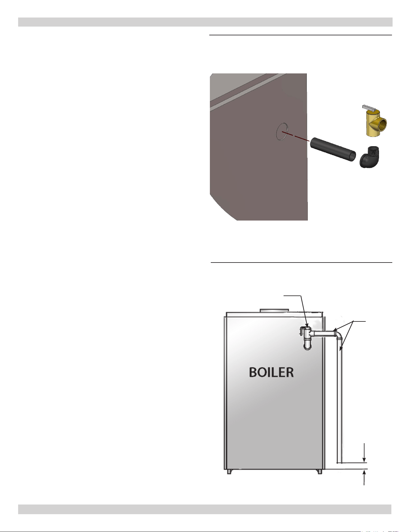
5.
Install Safety Relief valve in rear section using
¾” nipple and street elbow provided with boiler. See
gures 6a and 6b.
A. Install safety relief valve with spindle in vertical
position.
B. Do not install shuto valve between boiler and
safety relief valve.
C. Install discharge piping from safety relief valve.
• Use ¾” or larger pipe.
• Use pipe suitable for temperatures of 375°F
(191°C) or greater.
• Individual boiler discharge piping shall be
independent of other discharge piping.
• Size and arrange discharge piping to avoid
reducing safety relief valve relieving capacity
below minimum relief valve capacity stated on
rating plate.
• Run pipe as short and straight as possible to
location protecting user from scalding and properly
drain piping.
• Install union, if used, close to safety relief valve
outlet.
• Install elbow(s), if used, close to safety relief valve
outlet and downstream of union (if used).
• Terminate pipe with plain end (not threaded).
6.
Verify clean cold water supply is available when
connecting to pressure reducing valve. Use sand
strainer or pump strainer when water supply is from
well.
SYSTEM PIPING
Follow instructions
to install discharge
piping from safety
relief valve to drain.
Figure 6a - Safety Relief Valve Installation
Check local
codes for
maximum
distance
from oor
or allowable
safe point of
discharge.
SAFETY RELIEF VALVE
DISCHARGE
LINE
Figure 6b - Discharge Piping From Safety Relief
Valve
PN 240013445, Rev. A [09/01/2021]
12
> LOW DESIGN WATER TEMPERATURE
SYSTEMS
> LARGE WATER CONTENT SYSTEMS
> PIPING ARRANGED FOR “POWER
PURGING” AIR OUT OF THE SYSTEM
PIPING, REFER TO THIS MANUAL’S
SECTION ON “FILLING THE SYSTEM
WITH WATER” OPTION #1
SYSTEM PIPING
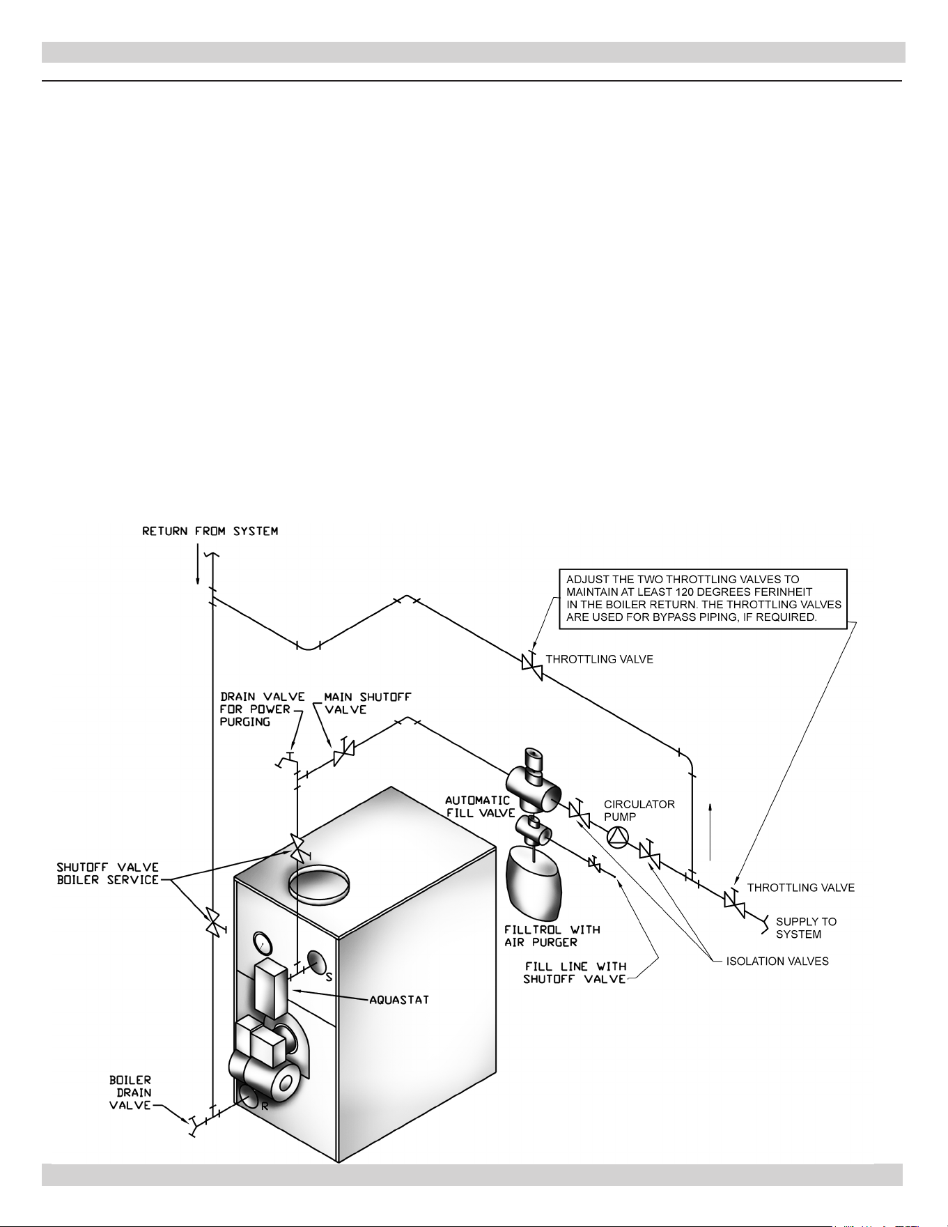
Figure 7 - Bypass Piping Arrangement Diagram
Low Design Water Temperature Systems (Below 140°
F) And Large Water Content Systems
Signicant condensation may form in this boiler and/
or venting system if boiler is operated with return
temperatures of less than 120° F.
Condensation is corrosive and can eventually cause damage
to boiler and venting system. Minimum design return water
temperature to prevent this condensation in boiler and
venting is 120°F.
Boiler used in heating system where design water
temperatures below 140°F are desired (e.g. radiant oor
heating), a 3-way or 4-way mixing valve or suitable
alternative (e.g. Bypass Piping Arrangement as shown in
Figure 7) is required to prevent low temperature (below
return 120°F) return water from entering boiler. When
using mixing valve, follow manufacturer’s installation
instructions.
Boiler connected to system having large water content
(such as former gravity system), use of Bypass Piping
Arrangement shown in diagram on following page is
suggested.
PN 240013445, Rev. A [09/01/2021]
13
> CIRCULATOR ON SUPPLY PIPING PUMPS AWAY
FROM EXPANSION TANK
NOTE: CIRCULATOR MAY ALSO BE INSTALLED
ON RETURN PIPING.
> PIPING ARRANGED FOR “POWER PURGING”
AIR OUT OF SYSTEM PIPING, REFER TO THIS
MANUAL’S SECTION ON “FILLING THE SYSTEM
WITH WATER” OPTION #1
SYSTEM PIPING
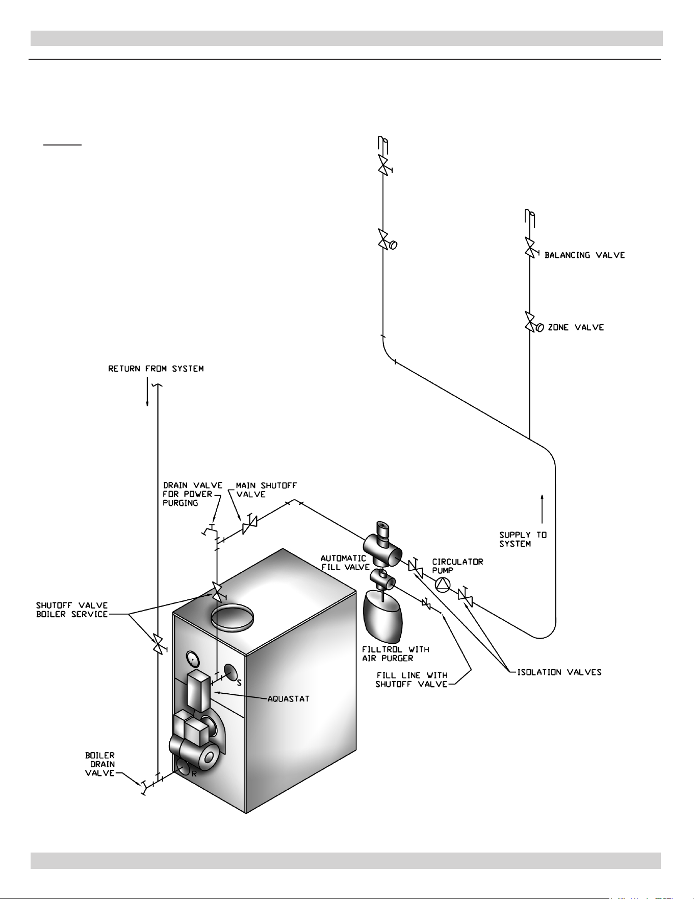
Figure 8 - System Piping Arrangement Zoning With Zone Valves
PN 240013445, Rev. A [09/01/2021]
14
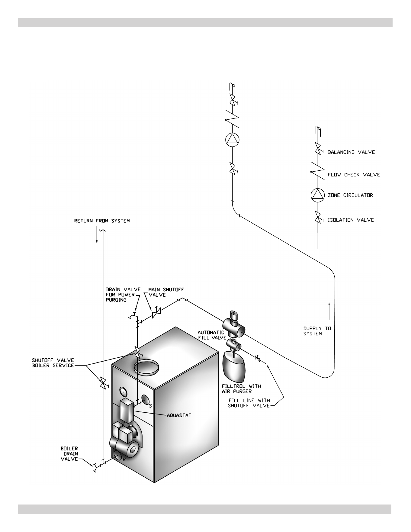
> CIRCULATOR ON SUPPLY PIPING PUMPS
AWAY FROM EXPANSION TANK.
NOTE: CIRCULATOR CAN ALSO BE INSTALLED
ON RETURN PIPING.
> PIPING ARRANGED FOR “POWER PURGING”
AIR OUT OF SYSTEM PIPING, REFER TO THIS
MANUAL’S SECTION ON “FILLING THE SYSTEM
WITH WATER” OPTION #1
SYSTEM PIPING
Figure 9 - System Piping Arrangement Zoning With Circulators
PN 240013445, Rev. A [09/01/2021]
15
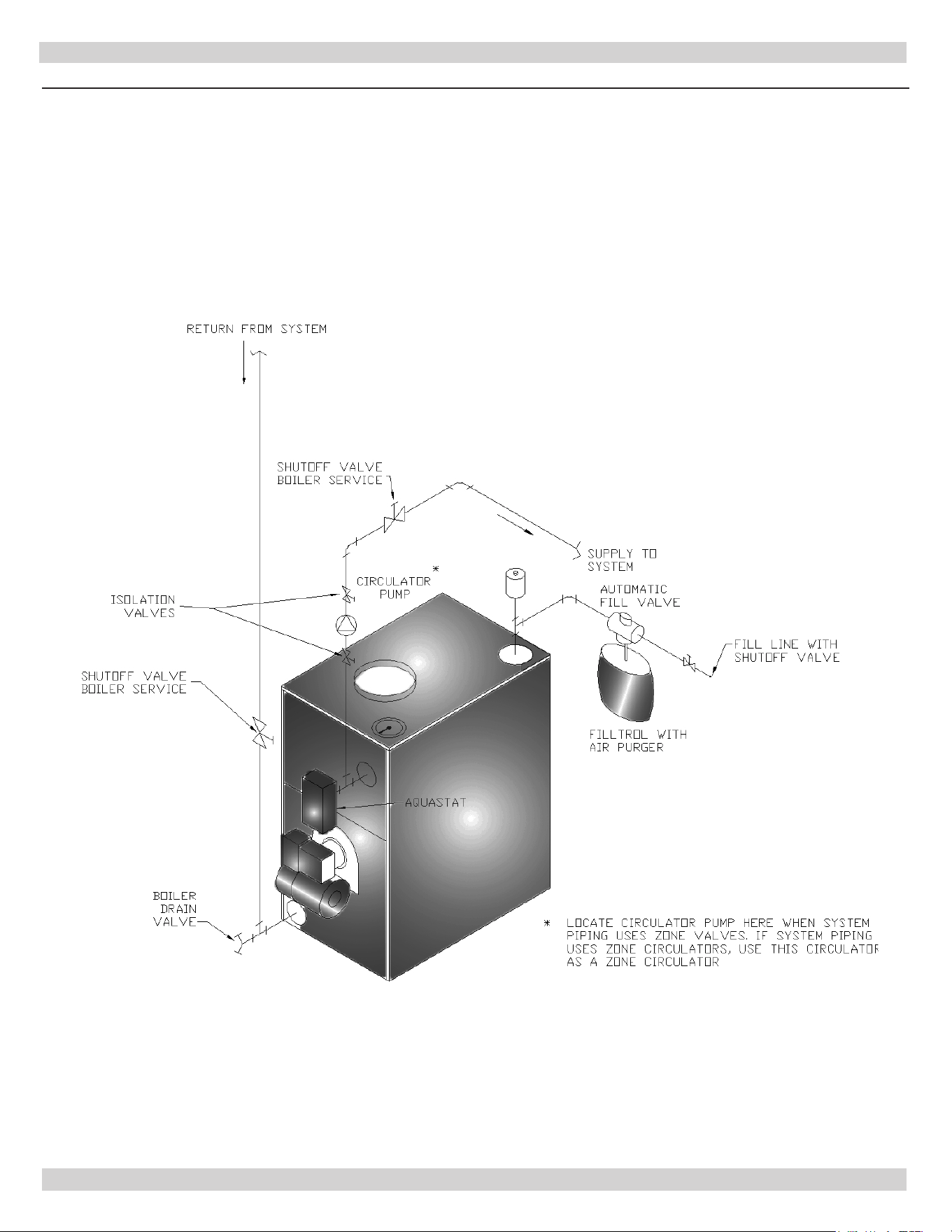
> DIAPHRAGM EXPANSION TANK MOUNTED
OFF THE BOILER
> CIRCULATOR ON SUPPLY PIPING PUMPS
AWAY FROM EXPANSION TANK
> PER THIS MANUAL, USE OPTION #2 IN
“FILLING THE SYSTEM WITH WATER”
> THIS PIPING ARRANGEMENT CAN BE USED
WITH ZONE VALVES OR ZONE
CIRCULATORS
Figure 10 - System Piping Arrangement Alternate Near Boiler Piping
SYSTEM PIPING
PN 240013445, Rev. A [09/01/2021]
16
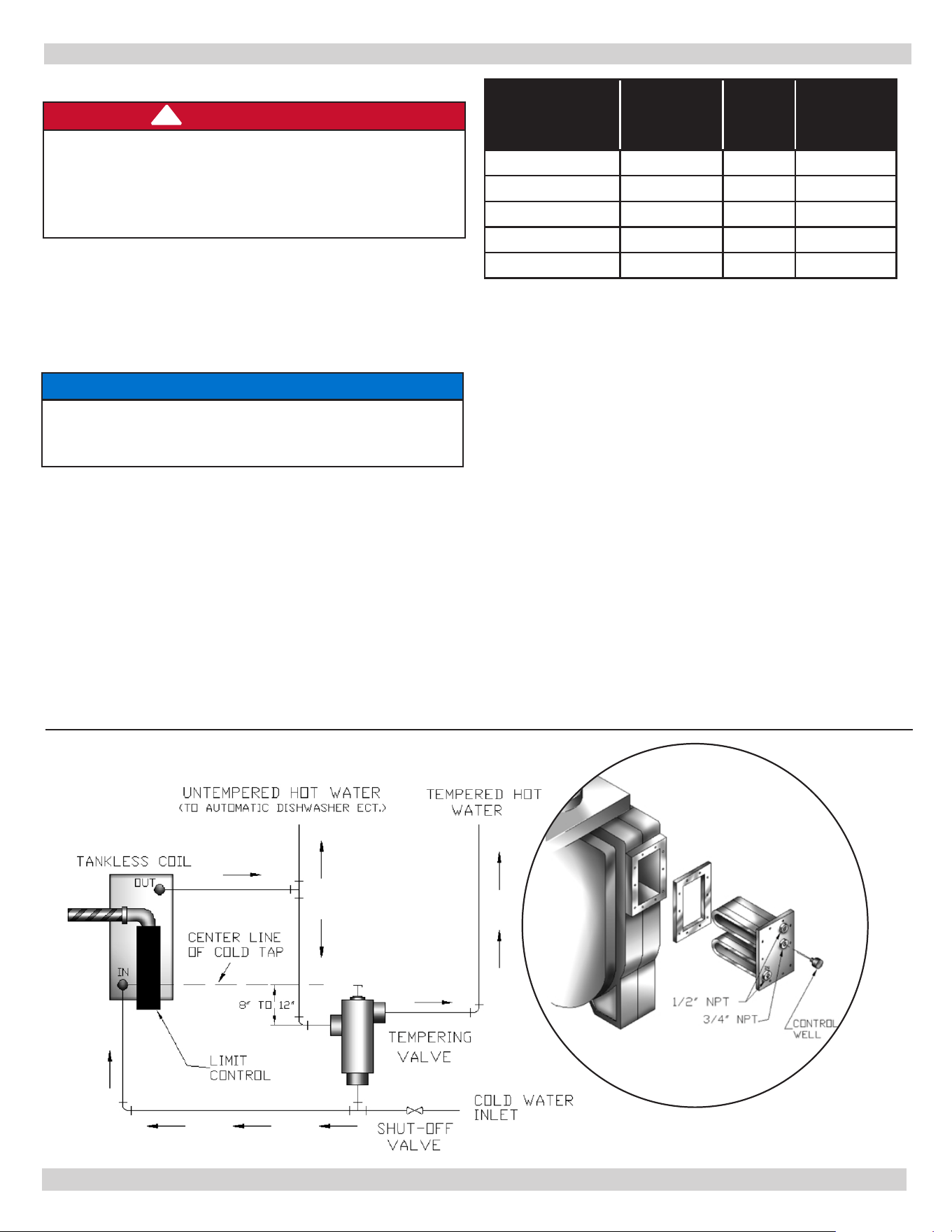
Boilers may be factory packaged with tankless heater
coil see gure below. Coil provides instantaneous heating
of water for domestic use if proper burner and water supply
line controls are used. Tankless coils are meant to provide
domestic hot water for intermittent draws, not continuous
ow.
NOTICE
Do not use tankless coil if your water is excessively
hard with lime or other deposits which will
accumulate inside the coil.
Factory Packaged with Tankless Heater Coil
h Hydrolevel Control
Combination high limit / low limit control is located on
tankless coil cover plate.
Tempering valve (mixing valve) is also recommended as
shown in gure below. Flow restrictor may be required on
tankless coil inlet piping so ow rates are matched to boiler
heat input (see table).
SYSTEM PIPING
Tankless Coil Piping Arrangement
Figure 11 -Tankless Coil Piping Arrangement
DANGER
Scald, Burn Hazard! Temperatures exceeding 120°F
will cause severe burns or death. Use of water
tempering device or mixing valve may be required
by Authority having jurisdiction, follow all codes as
required before leaving installation.
!
PN 240013445, Rev. A [09/01/2021]
Boiler
Model
Burner
Firing
Rate (gph)
Input
(MBH)
Tank less
Rating
(gpm)‡
3KWC0.80(T) 0.80 112 3.05
4KWC1.00(T) 1.00 140 3.25
4KWC1.25(T) 1.25 175 3.50
5KWC1.35(T) 1.35 189 3.60
5KWC1.55(T) 1.55 217 3.80
‡ Gallons of water per minute heated from 40°F to 140°F with
200°F boiler water temperature, intermittent draw
17
Antifreeze must be nontoxic, type specically intended
for use in closed hydronic heating systems. Under no
circumstances should automotive antifreeze be used.
Antifreeze used in any boiler may reduce capacity by
10% or more and increase fuel consumption. Tankless
coil performance will fall as concentration of antifreeze is
increased. Refer to boiler and piping water volumes tables
in this manual.
BOILER WATER VOLUMES
Number of
Boiler Section
Total Volume
(Gallons)
3 9.6
4 11.6
5 13.7
PIPING WATER VOLUMES
PIPE SIZE
COPPER PIPE
FACTOR
STEEL PIPE
FACTOR
½” 82.5 63.5
¾” 40.0 36.0
1” 23.3 22.2
1 ¼” 15.3 12.8
1 ½” 10.8 9.5
2” 6.2 5.8
Divide total length of piping in feet by appropriate factor
in table to determine volume in gallons.
Check your chimney to make certain that it is right size,
properly constructed and in good condition.
See Table “Recommended Minimum Chimney Sizes”.
For additional chimney design and sizing information,
consult latest revision of the ASHRAE HVAC Systems and
Applications Handbook, Gas Vent and Fireplace Systems; or
the National Standard for Chimneys, Fireplaces, Vents and
Solid Fuel Burning Appliances, ANSI/NFPA 211.
RECOMMENDED MINIMUM CHIMNEY SIZES
FIRING RATE
(gph)
CHIMNEY
HEIGHT (ft)
NOMINAL
CHIMNEY
ROUND
LINER INSIDE
SQUARE
LINER INSIDE
0.60 1.30 15 8” x 8” 6” 6 ¾” x 6 ¾”
1.35 1.80 15 8” x 8” 7” 6 ¾” x 6 ¾”
For elevations above 2,000 feet above sea level, add 3 feet to the chimney heights.
For oil red boilers for connections to vents or chimneys,
vent installations shall be in accordance with applicable
provisions of NFPA-31 Standard for the installation of
Oil-Burning Equipment (latest edition) and applicable
provisions of local building codes.
ANTIFREEZE IN THE SYSTEM
CHIMNEY AND CHIMNEY CONNECTIONS
NOTICE
Fresh air (ventilation) is important to proper
venting. Ventilation and venting are two parts of the
same system. Inadequate ventilation will result in
inadequate venting. Always be sure to have enough
ventilation to support proper venting.
Sidewall Venting With Listed Power Venter
— This boiler is not approved for direct sidewall horizontal venting.
— In the U.S. : Per section E.11 of NFPA 31-2020 Standard for the Installation of Oil Burning Equipment, a listed
power venter providing mechanical draft may be used when approved by the Authority having jurisdiction. Select
the listed power venter to match the BTU per hour input of the boiler being vented. Follow all manufacturer’s
installation and operating instructions for venting and termination included with the power venter.
PN 240013445, Rev. A [09/01/2021]
18
ALTERNATE POSITIONS
TOP
TOP
DRAFT REGULATOR
VANE
CRIMPED END
BALANCED WEIGHT
DRAWBAND
LAST PIECE
INSTALLED
MUST SLOPE UP
AT LEAST 1/4 INCH
PER FOOT OF
HORIZONTAL RUN
MUST BE AT LEAST 4
INCHES THICK -
AND BE TIGHT.
TIGHT
CLEAN-OUT
DOOR
SEALED IN
THIMBLE
TIGHT, SMOOTH,
CORRECTLY SIZED.
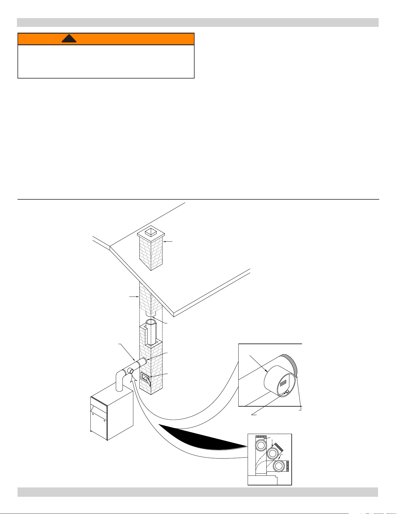
Minimum Height:
Must be 3 FT higher than
highest part of passage through roof.
Must be at least 2 FT higher than
any neighboring object within 10 FT.
Must have unobstructed top opening
.
TYPICAL CHIMNEY CONNECTION
CHIMNEY AND CHIMNEY CONNECTIONS
WARNING
Fire Hazard. Maintain minimum vent pipe clearance of
9” from surface of vent to wood and other combustible
materials. Failure to comply may result in death or
serious injury.
!
Figure 12 -
Typical Chimney Connection
Chimney Connector And Draft Regulator
• Venting the boiler requires 6” diameter chimney
connector pipe and use of manufacturer provided draft
regulator.
• Regulator, when properly installed, automatically
controls the draft.
• Install in horizontal section of pipe, may also be
installed in angled or vertical section of pipe.
• Verify “top” of regulator is at the top and short pipe
section which holds the vane is horizontal.
• Even though locating draft regulator close to chimney
reduces noise, install draft regulator as close as
practicable to the boiler.
• Install chimney connector, start at boiler with vertical
pipe, elbow, then install draft regulator horizontally.
• When regulator is in place, start at chimney and work
back to the regulator.
• Join the two sections with draw-band.
• Horizontal pipe must slope up toward the chimney at
least 1/4 inch per linear foot of venting.
• Chimney connector must not leak and must be rmly
supported.
• Join each section with at least two sheet metal screws.
Support every second section with a stovepipe wire.
PN 240013445, Rev. A [09/01/2021]

19
THERMOSTAT
Install 24 Volt thermostat (not provided) in proper location.
Location of thermostat has eect on boiler system operation.
Follow instructions included with thermostat.
GROUNDING
Permanently ground boiler according to local codes and
latest revision of the National Electrical Code. Run 14
gauge or heavier copper wire from boiler to grounded
connection in service panel or properly driven and
electrically grounded ground rod.
ELECTRIC POWER SUPPLY
Installation must comply with the latest revision of the
National Electrical Code, any other national, state, or local
codes or regulations.
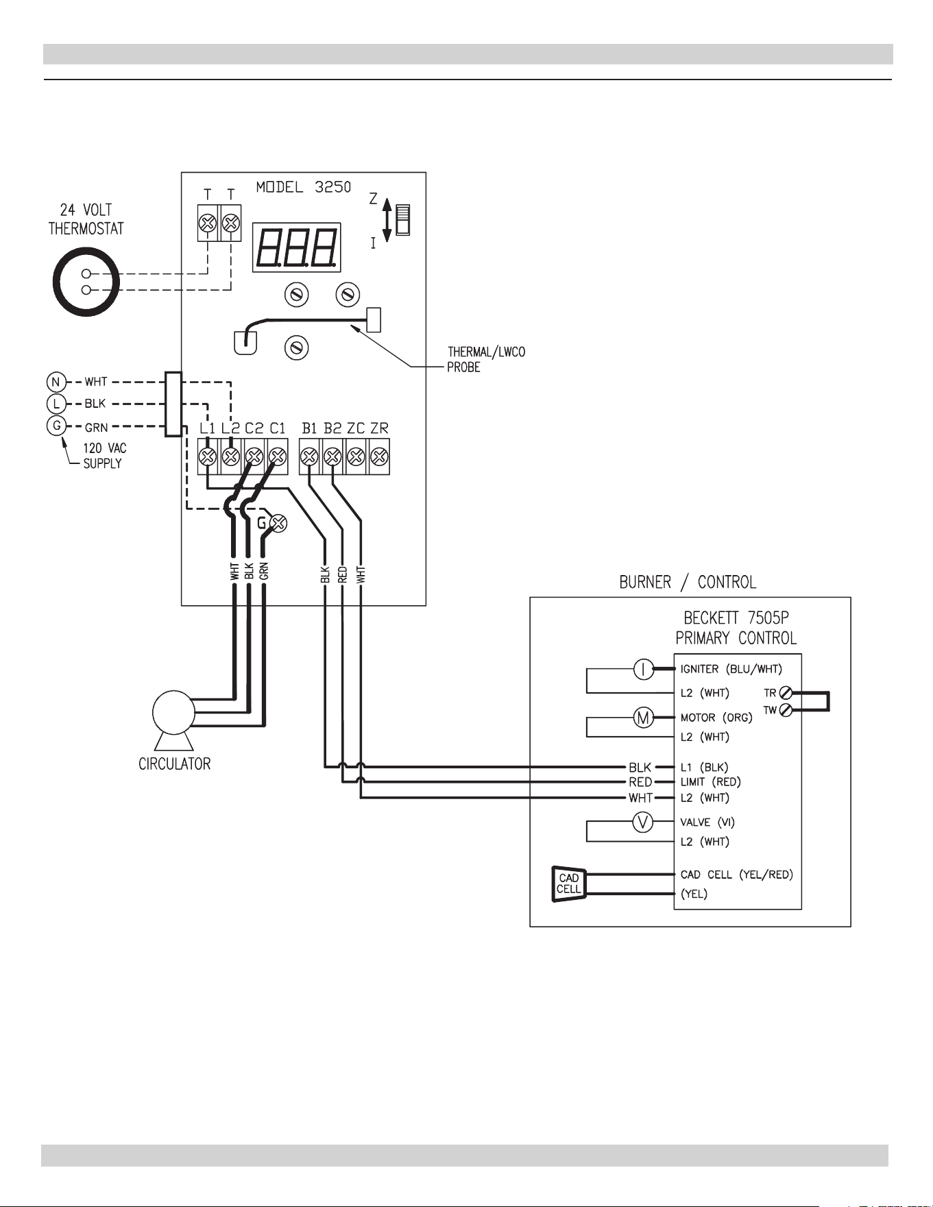
Connect 120 volt electrical supply to L1 and L2 terminals
and two thermostat wires to T and T terminals on
Hydrolevel limit control
Run separate circuit from separate over current protection
device in your electrical service entrance panel. Minimum
15 ampere circuit. Locate shuto switch at boiler. Turn o
during any maintenance. Solder and tape or securely fasten
connections with wire nuts.
OIL BURNER WIRING
For boilers packaged with oil burners, burners are factory
wired.
ELECTRICAL CONNECTIONS
WARNING
Electrical shock hazard. Turn OFF electrical power
supply at service panel before making electrical
connections. Failure to do so could result in death
or serious injury.
!
PN 240013445, Rev. A [09/01/2021]
20
ELECTRICAL WIRING
Figure 13 -
Boiler With Hydrolevel 3250 Control
PN 240013445, Rev. A [09/01/2021]

21
FILLING THE BOILER
How A Hot Water System Operates
Entire heating system (boiler, piping, and radiation units)
is lled with water. As water in the boiler is heated, it
is circulated from top of boiler through supply main to
radiation units. Cooler water in radiation units ows back
through return piping through return main into the boiler.
This arrangement provides positive and rapid response to
the thermostat.
Filling The System With Water
OPTION #1 This method utilizes boiler piping as shown in
gures 7, 8 and 9.
A. Close main shuto valve, isolation valves, and zone
valves (if applicable). If bypass piping is installed,
also close two throttling valves. Leave boiler service
shuto valve (if installed) and balancing valves to
each heating zone fully open.
B. Open following valves in order: drain valve for power
purging, isolating valves before and after boiler
circulator (if applicable), both throttling valves (if
applicable), and then open ll line shuto valve. Water
will ll bypass piping and push air through piping and
out power purging drain valve. When power purging
drain valve runs air free, close bypass piping throttling
valve (leaving throttling valve to supply piping fully
open).
C. Next, open isolation valve (or zone valve) to rst
zone. Water will ll piping and push any air out power
purging drain valve. When power purging drain valve
runs air free, close isolation valve or zone valve).
Repeat this procedure for remaining heating zones.
D. Once all zones are lled with water and purged of air,
close power purging drain valve and ll line shut o
valve, open main shuto valve, and adjust throttling
valves and balancing valves as required.
OPTION #2
• Close air vents on all radiation units.
• Open valves to radiation units. Verify boiler drain valve,
expansion tank drain cock, and air bleed screw on
expansion tank drain tting are closed.
• Open ll valve on piping to expansion tank.
• Open water inlet to boiler and leave it open.
• Open air vent on lowest radiation unit.
• When all air has escaped and water starts to ow from
vent, close it.
• Go to next radiation unit, and repeat this process until
nishing with highest radiation unit.
• If heating system has automatic vents, this manual
venting is unnecessary but it will speed up proper lling
of the system.
If system is a closed expansion tank system, automatic ll
valve is needed. Leave automatic ll valve open to rell
system automatically as needed.
Note initial ll pressure on boiler’s temperature / pressure
gauge, which should be 10-15 psig. Any lowering of
pressure from its initial ll pressure indicates loss of water
due to leakage. Automatic ll valve should then compensate
for this water pressure loss. If it does not, manually open
this valve to rell system until needle is again pointing to
same pressure reading. Instructions are packaged with
valve.
PN 240013445, Rev. A [09/01/2021]

22
OPERATING THE BOILER
Draft Regulators: Barometric draft regulator is required
for controlling draft through boiler. Mount barometric draft
regulator in chimney connector. Refer back to section on
“Chimney And Chimney Connections”. Once draft regulator
is installed, use draft gauge to adjust to proper opening:
A. Combustion chamber over re draft shall be -0.01”
WC to -0.02” WC.
B. Stack draft will be approximately -0.02” WC. to
-0.04” WC.
C. Larger installation, greater draft will be required in
stack to obtain desired over re draft.
Start: Fill entire system with water. Vent all air from
system following section for Filling The Boiler.
Fuel Units And Oil Lines:
• Install oil line(s) to oil burner.
• Recommend using heavy wall copper tubing and
ared ttings, not compression ttings.
• All connections and joints must be absolutely airtight.
Use an appropriate non-hardening thread sealing
compound on the threaded connections, not Teon
tape.
• See fuel unit data sheet furnished with the burner for
sizing, lift, and length of tubing recommendations.
Oil burner is equipped with single stage fuel unit for single
pipe installation. This is satisfactory where fuel supply is on
same level as or above burner permitting gravity ow of oil.
Per NFPA 31 requirements, never exceed 3 psig pressure to
inlet side of fuel unit.
When necessary to lift oil to burner, two pipe installation
is required. Run return line between fuel unit and oil
supply. Refer to fuel unit instructions furnished with burner
for specic instructions on two pipe installations. Do not
exceed fuel unit manufacturer’s recommendations for
running vacuum.
NOTICE
If lift exceeds 14 feet for Beckett burners, two stage
fuel unit is required with return line.
Install oil lter of adequate size inside building between
tank shuto valve and oil burner. For ease of servicing,
locate shuto valve and lter near oil burner.
Air Supply For Combustion:
• Do not install boiler in rooms with insucient air, unless
corrective steps are taken.
• It may be necessary to install windows or cut holes in
a door to rooms used for supply air to obtain sucient
combustion air and prevent less than atmospheric air
pressure in that room.
• If there is a lack of combustion air, burner ame will be
dark orange and formation of soot will occur in heating
unit.
• In buildings of conventional frame, brick, or stone
construction that do not have utility rooms, basement
windows, or stair doors, air inltration is normally
adequate to provide enough air for combustion and for
operation of barometric draft control.
• Room used for supplying combustion air should be
isolated from any area served by exhaust fans.
• Refer to the section "Fresh Air For Combustion" for
additional sizing guidelines.
Nozzles And Electrodes: Use proper size, spray angle,
and spray pattern nozzle.
To install nozzle, remove nozzle line electrode assembly,
if necessary remove retention ring assembly, and install
and tighten nozzle. Take care not to damage electrode
insulators or bend electrode tips.
After installing nozzle, reassemble nozzle line electrode
assembly and set electrode tip spacing.
Depending on burner type, electrode tip spacing may
need to be set prior to reassembling nozzle line electrode
assembly.
Refer to following pages for setting electrode tip spacing.
Final Burner Adjustments: Final burner adjustments
must be made using combustion test instruments. Refer
to preliminary burner settings charts for initial startup. Set
burner accordingly.
• Check draft over re to verify it is between -0.01” WC
and -0.02” WC, adjust draft as necessary.
• After operating 10 minutes to warm up boiler, use
combustion test equipment to take smoke reading in
ue pipe between boiler and draft regulator.
• Smoke reading should be zero to trace (Shell Bacharach
Scale).
• A new boiler requires more than 10 minutes to burn
clean due to oil lm on new heat exchanger.
• If smoke reading is zero, gradually close burner’s air
adjustment to obtain smoke reading showing trace
smoke reading. Once smoke reading is trace, measure
CO
2
and as insurance margin increase air to suciently
reduce CO
2
by ½% to 1%.
If clean re cannot be obtained, it is necessary to verify
burner head and electrode alignment. Proper electrode
alignment gures are presented on following pages. If
re continues to be smoky, replace nozzle with correct
replacement.
Once burner is completely adjusted, start and stop burner
several times to assure good operation with no uttering
or rumbling. Verify there are no oil leaks. Record nozzle
size, oil pressure, combustion readings, and air settings on
tag or label attached to burner or, boiler.
PN 240013445, Rev. A [09/01/2021]
23
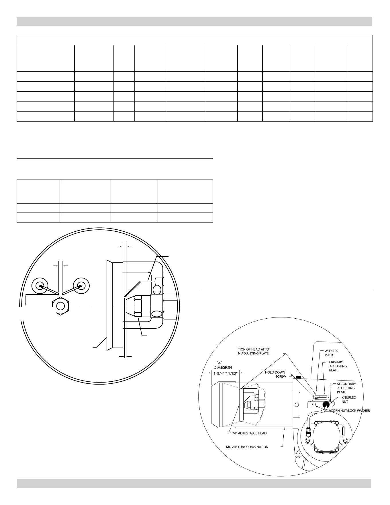
BECKETT AFG BURNER ELECTRODE ADJUSTMENTS VARIABLE (V1) HEADS
BOILER DIMENSION "N" DIMENSION "H"
MODEL (electrode to nozzle) (head to nozzle)
5EW 1/16" 7/32" - 9/32"
DIMENSION "H"
SEE ABOVE
5/32
GAP
5/16 ABOVE
LI or V1 HEAD
DIMENSION "N"
SEE ABOVE
ELECTRODE
NOZZLE
Boiler
Model
Dimension “N”
(electrode to
nozzle)
Dimension “X”
(above nozzle
Center)
Dimension “Z”
(end of air tube
to head)
3 Section 1/16” 5/16” 1-3/4” +/- 1/32”
4/5 Section 1/8” 1/4” 1-3/4” +/- 1/32”
PRELIMINARY BURNER SETTINGS
Figure 14 - Beckett AFG Burner Electrode Adjustments
(V1, L1) Heads
Figure 15 -
Beckett AFG Variable (V1) Head
Adjustments and Settings
BECKETT AFG
BOILER MODEL
BURNER
MODEL
INPUT
RATE
[gph]
INSERTION
DEPTH
DELAVAN OIL
NOZZLE
PUMP
PRESSURE
[psi]
LOW
FIRE
BAFFLE
BURNER
HEAD
HEAD
SETTING
AIR
SHUTTER/
BAND
STATIC
PLATE
3KWC0.80(T)
AFG50MBAS
0.80 2-1/4" 0.65-70°W 150 YES L1 N/A 10/1 3-3/8"
4KWC1.00(T)
AFG50MDASN
1.00 2-1/2" 0.85-60°A 140 NO V1 0 6/1 2-3/4"
4KWC1.25(T)
AFG50MDASN
1.25 2-1/2" 1.00-60°W 155 NO V1 0 10/1 2-3/4"
5KWC1.35(T)
AFG50MDASN
1.35 2-1/2" 1.10-60°B 150 NO V1 0 7/1 2-3/4"
5KWC1.55(T)
AFG50MDASN
1.55 2-1/2" 1.25-60°B 155 NO V1 2 10/2 2-3/4"
Note: All burners re at an overre draft of -0.02 inches w.c. The burner settings provided are for initial startup only.
Final adjustment must be made using combustion test instruments.
7/32” - 9/32”
DIMENSION “X”
SEE ABOVE
“Z” DIMENSION
PN 240013445, Rev. A [09/01/2021]
24
This boiler is equipped with the Hydrolevel 3250-Plus
temperature limit and operating control.
Consult Hydrolevel literature provided with boiler for
detailed information on various features of control and
instructions for setting up the control.
High limit is factory set to 190°F.
Low limit is factory set to OFF. This setting is applicable to
models without tankless coil so they operate as a cold start
boiler.
Low limit is used to maintain temperature in boilers
equipped with tankless coils. For models with tankless
coil, turn the low limit dial clockwise until the desired
temperature is displayed.
Limit settings may be varied to meet the requirements of
the installation. Low limit set point must be at least 10°F
less than high limit set point.
Economy feature is factory set to 1 for single zone system.
Adjust per Hydrolevel instructions.
Low water cut o feature is factory set for automatic mode.
Refer to the Hydrolevel instructions to activate manual
reset mode or to disable low water cut o feature.
CHECKING AND ADJUSTING CONTROLS
NOTICE
Installer shall follow these instructions carefully.
WARNING
Burn, scald hazard. Do not attempt to start the
burner when excess oil has accumulated, when
the unit is full of vapor, or when the combustion
chamber is very hot.
!
Adjust Thermostat Heat Anticipator or
Thermostat Cycle Rate According to Instructions
Included With The Thermostat
Check Thermostat Operation:
Follow instructions included with your thermostat.
Locate thermostat ve feet above the oor on inside wall.
Locate thermostat to sense average room temperature,
avoid the following:
THERMOSTAT LOCATIONS TO AVOID
DEAD
SPOTS
HOT SPOTS COLD SPOTS
Behind
doors
Concealed pipes Concealed pipes
or ducts
Fireplace
TV sets Stairwells drafts
Corners &
alcoves
Radios Doors drafts
Lamps
Unheated room
on other side of
wall
Direct sunlight
Kitchens
When temperature on thermostat is set above indicated
thermostat temperature, boiler’s burner should start. Verify
that when room temperature reaches selected temperature
setting, thermostat should turn boiler’s burner o, and
once room temperature falls few degrees boiler starts
operating again.
Do not start burner unless all cleanout doors are
secured in place.
Sequence of Operation
• Thermostat calls for heat.
• Circulator turns on.
• Limit checks boiler water temperature. Burner ignition
delayed until limit determines call for heat cannot be
met by residual heat in boiler and heat distribution
system.
A. See limit literature for additional information.
B. Burner delay by-passed for tankless heat call for
heat. Burner ignition begins immediately.
• Burner and circulator operation continues until
thermostat stops call for heat.
PN 240013445, Rev. A [09/01/2021]

25
Annually: Recommend ue passages, combustion
chamber area (target wall, re door insulation,
durablanket), burner adjustment, control operation, and
boiler seals (re door gasket or silicone seal, cast iron
sectional seals, ue collector) be checked once each year
by trained Service Technician.
Before start of each heating season (or when
system has been shut down for extended periods of time)
recheck whole system for water, oil, and vent piping leaks.
Replace or patch any leaks or seals that are faulty.
Vent Pipe: Visually inspect entire venting system
once a month for any signs of leakage, deterioration, or
soot build up. If vent pipe shows any signs of leaking or
deterioration, replace it immediately. If it shows any signs
of soot build up, clean vent pipe and have burner settings
and combustion checked by competent professional.
Safety Relief Valve: Valve should open automatically
when system pressure exceeds pressure rating (usually 30
psi) of safety relief valve. Should valve ever fail to open
under this condition, shut down the system. Drain system
until system pressure is reduced below safety relief valve
pressure rating. Contact Service Technician to replace the
valve and inspect heating system to determine cause, may
indicate equipment malfunction. Safety relief valve should
be tested monthly during heating season. Prior to testing,
make certain discharge pipe is properly connected to valve
outlet and arranged so as to contain and safely dispose of
boiler discharge. Hold trip lever fully open for at least ve
seconds in order to ush free any sediment that may lodge
on valve seat. Permit valve to snap shut. Refer to valve
manufacturer’s instructions packaged for more details.
Conventional Expansion Tank: Tank may become
water logged or may receive excess air. Frequent
automatic opening of safety relief valve indicates water
logging. High boiler temperature accompanied by
unusually low radiation unit temperature (and “knocking”
noises) indicates excess air in the tank. To correct either
condition, close valve between boiler and tank. Drain tank
until empty. Check all tank plugs and ttings, tighten as
necessary. Open valve between boiler and tank. Water will
rise to normal height in tank if system has automatic ll
valve, otherwise manually rell system.
Diaphragm Expansion Tank: Tank may become
water logged. Frequent automatic opening of safety relief
valve indicates water logging. High boiler temperature
accompanied by unusually low radiation unit temperature
(and “knocking” noises) indicates excess air in the tank. To
correct this condition, replace diaphragm expansion tank.
Water System: If system is to remain out of service
during freezing weather, drain it completely (water left in
system may freeze and will crack pipes and/or boiler).
Tankless Coil (Or Cover Plate) Gasket: Check
gasket at least twice year for leakage, replace if necessary.
If gasket is replaced, make sure when coil plate (or cover
plate) is reattached, ten nuts are torqued in alternating
pattern to insure equal force is applied to entire gasket
creating good seal. Nuts should be torqued so gasket does
not squeeze out from behind the plate.
Control Well: Remove control well every ve years and
clean any scale or sediment deposits from all parts exposed
to boiler water. After cleaning, reinstall well using pipe
sealing compound. Teon tape is not recommended.
Oil Burner Maintenance
Perform following preventative maintenance annually, prior
to heating season is preferred.
1.
Do not oil- Oil burner motors are permanently
lubricated.
2.
Fuel Filter- Replace to prevent contaminated guel from
reaching nozzle. Partially blocked fuel lter can cause
premature failure of fuel pump.
3.
Fuel Pump Unit- Replace pump screen and clean
pump unit to maintain fuel delivery to nozzle.
4.
Ignition Electrodes - Clean and adjust per
manufacturer’s recommentdations, to maintain reliable
ignition of oil.
5.
Nozzle- Replace to maintain safe and reliable
combustion eciency. Replace with nozzle as required
in charts located in this manual.
6.
Fan and Blower Housing- Must be kept clean, free
of dirt, lint and oil to maintain proper amount of air fuel
requires to burn.
7.
Check Final Burner Adjustments.
Never burn garbage or paper in the unit, never leave
combustible material around it.
MAINTENANCE
WARNING
Burn and scald hazard. Do not attempt to start
the burner when excess oil has accumulated, when
the unit is full of vapor, or when the combustion
chamber is very hot. Failure to follow these
instructions could result in death or serious injury.
!
PN 240013445, Rev. A [09/01/2021]
26
OIL BOILER CLEANING:
1.
Shut o all electrical power to boiler / burner and shut
o fuel oil supply.
2.
Remove vent pipe from boiler top. Inspect pipe and
chimney for signs of corrosion and deterioration. Clean
out base of chimney. If vent pipe shows any signs
of corrosion or deterioration, replace immediately. If
chimney damage or deterioration is discovered, contact
competent professional.
3.
Remove top jacket panel screws (5), brass wing nuts
(2) holding ue collector top, and ue collector top.
Inspect gasket on underside of ue collector and
replace as necessary.
4.
Before beginning to clean ue passageways, ensure
combustion chamber blanket is covered. If blanket is
not covered prior to cleaning, replace blanket once
cleaning is completed.
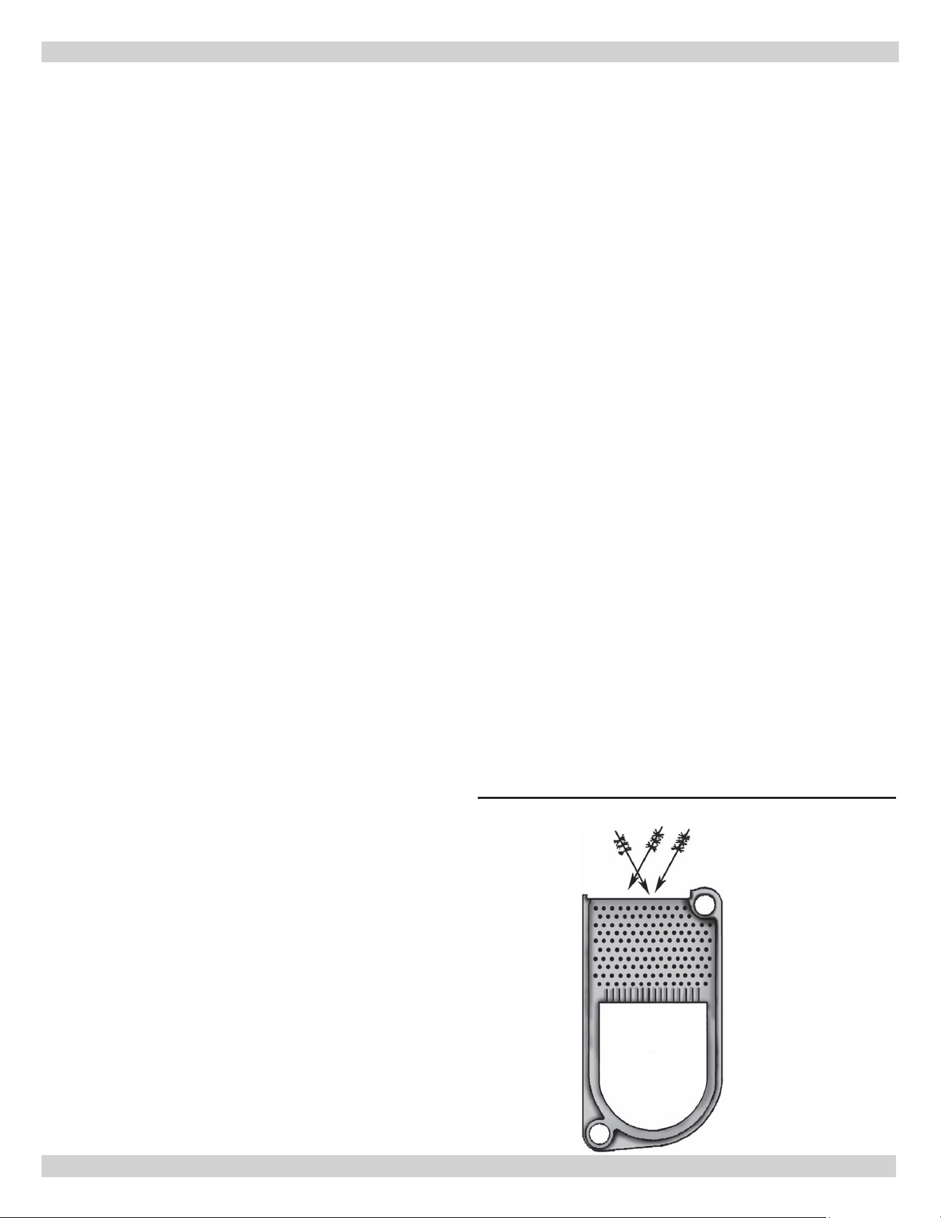
5.
With access to ue passageways, remove soot from
reside surfaces by brushing diagonally through ue
passages. Brushing is easier by cutting end of ue
brush o and inserting into a drill. When brushing, take
care not to damage target wall with ue brush. See
gure 16.
6.
Carefully vacuum soot accumulations from combustion
chamber area, be careful not to damage any refractory
or blanket insulation. To gain access to combustion
chamber rst double check the shut o valve on fuel
oil line is closed and disconnect fuel oil line. Remove oil
burner from re door. Remove re door.
7.
Inspect target wall, re door refractory, and
combustion chamber blanket (when included) for
cracking and deterioration. If there is signs of cracking
or deterioration, replace refractory or blanket before
reassembling burner / front plate.
8.
Inspect door’s braided gasket for wear and damage.
Replace when necessary with braided gasket of same
material and size. See repairs parts manual.
9.
Inspect and clean oil burner.
Important operating and maintenance requirements:
• Keep boiler and area around it clean
• Never burn refuse or any material other than
specied fuel in your boiler
• Have your boiler checked each year by qualied
technician
OIL BOILER CLEANING INSTRUCTIONS
Figure 16 -
Brush Diagonally Through Flue
Passages
1.
Verify all electrical power to boiler / burner and fuel
supply to burner are shut o.
2.
With oil burner removed from re door, clean any soot
accumulations from end of burner and if applicable
burner head.
3.
Remove burner drawer assembly, clean electrodes
and reset electrode spark gap per manufacturer’s
recommendations. Refer to section on OPERATING
THE BOILER Nozzles and Electrodes.
4.
Replace oil nozzle with same size and type
recommended for use on this boiler.
5.
Install burner drawer assembly making sure head
location (and size if applicable) are per manufacturer’s
recommendations. If burner being used has damaged
head, replace head with same head recommended for
use on this boiler.
6.
Inspect and clean oil burner blower wheel.
7.
Remove oil pump cover and clean / replace pump
screen. Carefully reassemble ensuring pump cover
makes proper seal.
8.
Securely fasten oil burner to re door.
9.
Replace fuel lter (if applicable).
10.
Reconnect electrical and fuel supplies.
11.
Fire burner, checking for proper combustion using
combustion test equipment and making adjustments
as necessary. Refer to section on OPERATING THE
BOILER Final Burner Adjustments.
12.
Insure all safety controls and operating controls are
functioning properly.
These are general instructions for cleaning an
oil burner.
For specics, consult burner manufacturer’s
instructions.
PN 240013445, Rev. A [09/01/2021]
27
You may avoid inconvenience and service calls by checking these points before you call for service:
IF YOUR SYSTEM IS NOT HEATING OR NOT GIVING ENOUGH HEAT . . .
POSSIBLE CAUSE WHAT TO DO
Thermostat is not set correctly Reset thermostat
Burner is not operating properly
Check ame. If it is yellow, the burner is not getting enough air.
Or, if ame is blue and noisy and seems to lift o the burner, the
burner is getting too much air. Contact your service technician.
No electric power to boiler
Check over-current protection. Check to be sure electric power
supply circuit is “ON”.
Controls out of adjustment Reset according to instructions.
Radiators not heating
Open radiator vents to excess air. Check ow control valve (if
used). It may be in closed position.
Circulating pump not running Check over-current protection. Check relay operation.
Poor electrical contact Check all control terminals and wire joints.
Chimney ue is blocked Have the chimney professionally cleaned.
Circulator running when boiler water
temperature is below low limit set
point (tankless coil boilers only)
Honeywell L7248L control - conrm ELL parameter on L7248L
control set to ON.
Refer to control instructions furnished with boiler.
RELIEF VALVE LEAKING . . .
POSSIBLE CAUSE WHAT TO DO
Corrosion and/or deposits on seat. Open valve manually. Allow water to run and clear valve seat.
Water logged expansion tank Drain tank, see instructions.
HAVE YOUR SERVICE TECHNICIAN CHECK ANY PROBLEM YOU
ARE UNABLE TO CORRECT.
SERVICE HINTS
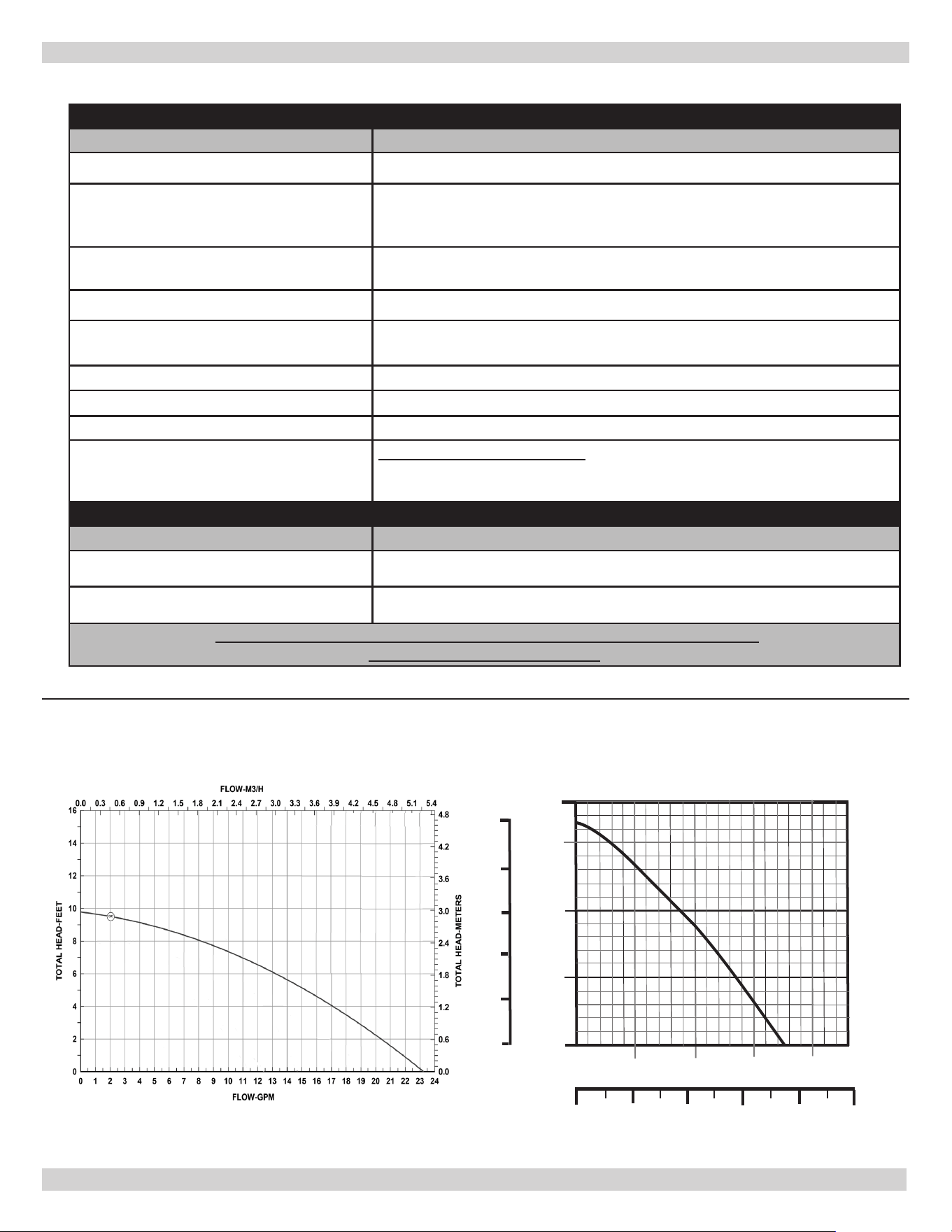
15
10
5
0
5
4
3
2
1
m Head
1 2 3 4 5
US GPM
5 10 15 20
m /h
3
Head (feet)
Figure 17 -
Pump Curves
007
Taco 007 Pump Curve Grundfos UP15-42F Pump Curve
PN 240013445, Rev. A [09/01/2021]

All specications subject to change without notice.
©2021 ECR International, Inc.
2201 Dwyer Avenue, Utica, NY 13501
Tel. 800 325 5479
www.ecrinternational.com
IMPORTANT
In accordance with Section 325 (f) (3) of the Energy Policy and
Conservation Act, this boiler is equipped with a feature that saves energy
by reducing the boiler water temperature as the heating load decreases.
This feature is equipped with an override which is provided primarily to
permit the use of an external energy management system that serves the
same function.
THIS OVERRIDE MUST NOT BE USED UNLESS AT LEAST ONE OF THE
FOLLOWING CONDITIONS IS TRUE:
• An external energy management system is installed that reduces the boiler water
temperature as the heating load decreases.
• This boiler is not used for any space heating
• This boiler is part of a modular or multiple boiler system having a total input of
300,000 BTU/hr or greater.
• This boiler is equipped with a tankless coil.