H
2
O
GLASS LINED
Indirect-Fired
Water Heaters
FOR SINGLE WATER HEATER
INSTALLATIONS
INSTALLATION, OPER ATION &
MAINTENANCE MANUAL
Certied to UL STD 174 and NSF/ANSI 372
Conforms to CAN/CSA STD C22.2 No. 110-94
H20 30 GL
H2O 40 GL
H2O 50 GL
H2O 80 GL
H2O 105 GL
MODELS
ECR International Inc.
2201 Dwyer Avenue, Utica, NY 13501
Tel. 800 325 5479
www.ecrinternational.com
PN 615000229 REV. G [10/01/2021]
R
2
PN 615000229 REV. G [10/01/2021]
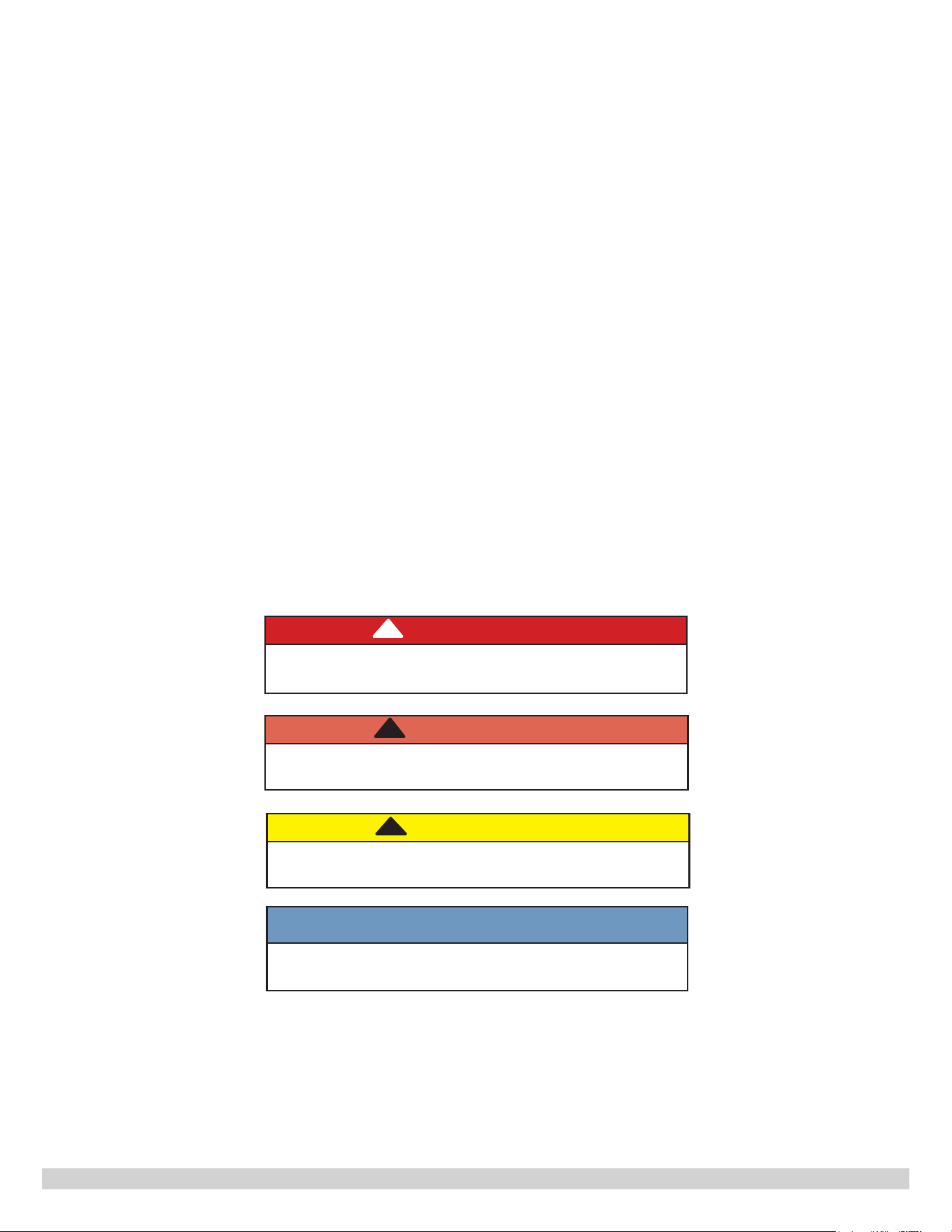
Hazard Denitions
The following dened terms are used throughout this manual to bring attention to the presence
of hazards of various risk levels.
SAVE THESE INSTRUCTIONS
CAUTION
Indicates a hazardous situation which, if not
avoided, could result in minor or moderate injury.
!!
WARNING
Indicates a hazardous situation which, if not
avoided, could result in death or serious injury.
!
DANGER
Indicates a hazardous situation which, if not
avoided, WILL result in death or serious injury.
!
NOTICE
Indicates information which should be followed to
ensure proper installation and operation.

3
PN 615000229 REV. G [10/01/2021]
Table of Contents
I. General Information ........................................................................ 4
II. Pre-Installation Considerations
......................................................... 6
III. Piping
..........................................................................................12
IV. Electrical Wiring
............................................................................18
V. Operation
.....................................................................................21
VI. Maintenance
.................................................................................23
VII. Troubleshooting
.............................................................................25
VIII. Critical Check Points After Installation
.............................................27

4
PN 615000229 REV. G [10/01/2021]
I. GENERAL INFORMATION
1. Important Safety Information - Read carefully
Installation shall conform to requirements of authority having jurisdiction.
All wiring on water heaters shall conform to requirements of authority having jurisdiction or in absence of such
requirements National Electrical Code.
Installation and service shall be performed by a professional installer or service agency.
WARNING
Burn, Scald, and Electrical Shock Hazard. Improper installation adjustment, alteration, service or
maintenance could result in death or serious injury. Read this manual and understand all requirements
before beginning installation.
This water heater contains very hot water under high pressure. Do not unscrew any pipe ttings or attempt
to disconnect any components of this water heater without assuring the water is cool and has no pressure.
Always wear protective clothing and equipment when installing, starting up or servicing this water heater to
prevent scalding injuries. Do not rely on the pressure and temperature gauges to determine the temperature
and pressure of the water heater. This water heater contains components that become very hot when the
connected hot water boiler is operating.
Do not touch any components unless temperature is conrmed to be cool.
Failure to follow the instructions in the order of this manual and all safety messages within could result in
death or serious injury.
!
To reduce the risk of excessive pressures and temperatures in this water heater, install temperature and pressure
protective equipment that meets the requirements for Relief Valves and Automatic Shuto Devices for Hot Water Supply
Systems, ANSI Z21.22, latest edition. This valve must be marked with a maximum set pressure not to exceed the marked
working pressure of the water heater. Install the valve following the instructions from the relief valve manufacturer and
the guidance presented in this document. A drain tube must be installed and oriented so that any discharge from the
pressure temperature relief valve will exit within 6 inches above, or at any distance below, the structural oor, and cannot
contact any live electrical part. The discharge opening must not be blocked or reduced in size under any circumstances.
These glass lined water heaters with single-wall heat exchangers meet the Uniform Plumbing Code for installation in
potable water systems provided:
• Boiler water, including additives, is practically non-toxic, having a toxicity rating of class 1 as listed in Clinical
Toxicology of Commercial Products, latest edition.
• Boiler water pressure is limited to a maximum 116 psig by an approved safety or relief valve.
• Heat transfer medium is potable water or contains only substances recognized as safe by the U.S. Food and Drug
Administration (FDA).
• Pressure of heat transfer medium is maintained less than normal maximum operating pressure of the potable
water system.
5
PN 615000229 REV. G [10/01/2021]
DO NOT store or use gasoline or any other ammable vapors or liquids in the vicinity of this appliance.
When installing or during the normal operation of this water heater, basic safety precautions, to reduce the risk of re,
electric shock, or injury, should be followed. Such precautions include but not limited to the following.
• Read all instructions of the water heater, hot water boiler, and all components in the heating system.
• Install or locate this water heater in accordance with the provided installation instructions.
• Use this water heater for its intended use as described in this manual.
• As with any appliance, close supervision is necessary when used by children.
• Do not operate this water heater if it is not working properly or if it has been damaged or dropped.
• This water heater should only be serviced by qualied personnel. Contact nearest authorized service facility for
examination, repair, or adjustment.
Maximum boiler water supply temperature to the indirect heat exchanger shall not exceed 240 °F (115 °C).
Manufacturer recommends use of water softening system in areas with hard water. Where water quality is unknown,
consult a qualied water treatment expert.
Improper water quality will reduce the life of the water heater. Avoid hard water, sediment, high or low PH and high
levels of chlorides in the domestic water. Verify PH levels fall between 6 and 8, and dissolved chlorides are less than 100
ppm. Use of a lter is required where sediment is greater than 5 microns in size in the water supplied to the unit.
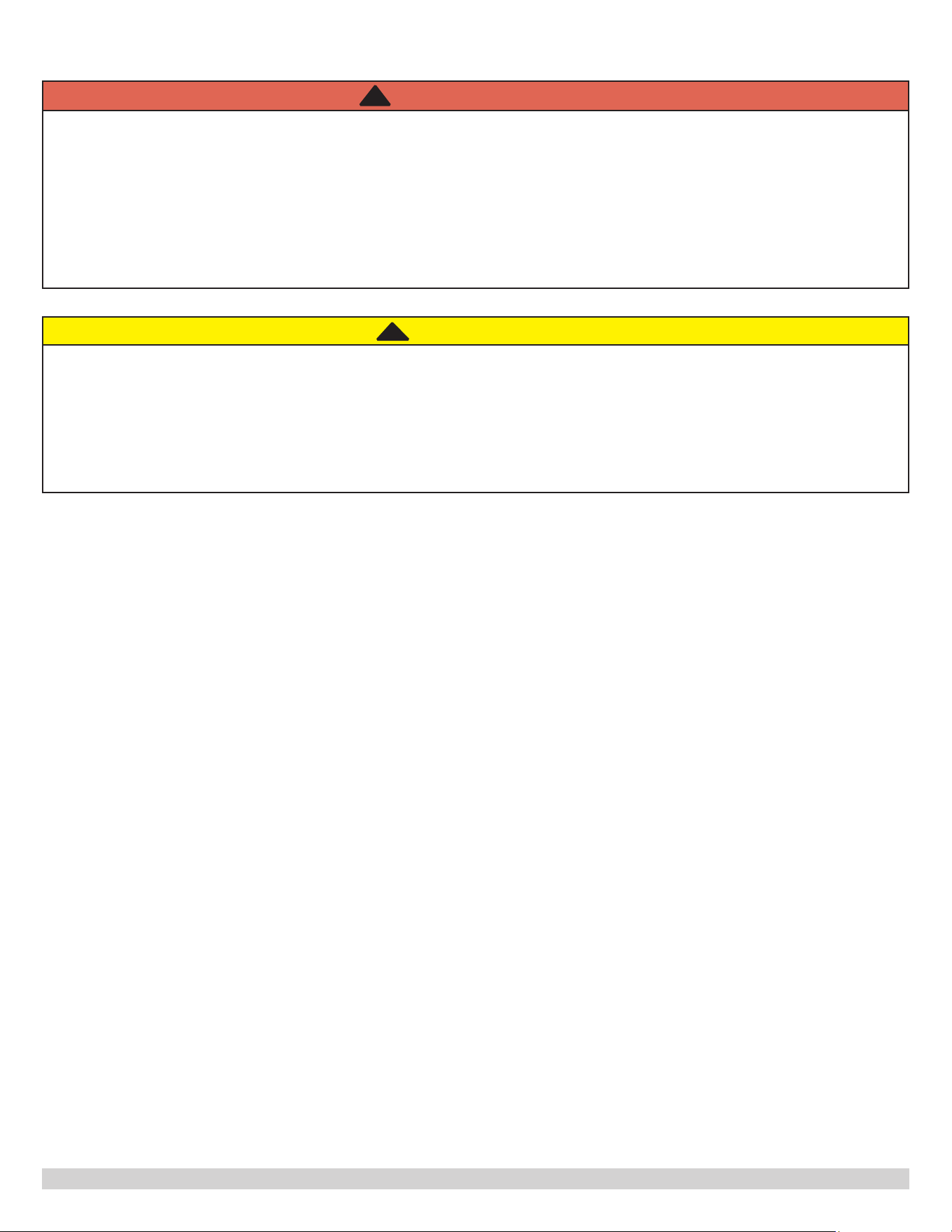
CAUTION
WHAT TO DO IF YOU SMELL GAS
• Do not try to light any appliance.
• Do not touch any electrical switch; do not use any phone in your building.
• Immediately call your gas supplier from a neighbor’s phone. Follow gas supplier’s instructions.
• If you cannot reach your gas supplier, call the re department.
!!
WARNING
Fire, Explosion Hazard. Hydrogen gas can be produced in a hot water system served by this water heater
that has not been used for a long period of time (two weeks or more).
Hydrogen gas is extremely flammable. To reduce the risk of injury under these conditions, it is
recommended that a hot water faucet be opened for several minutes at the kitchen sink before using
any electrical appliance connected to the hot water system.
If hydrogen is present, there may be an unusual sound such as air escaping through the pipe as the
water begins to flow. There should be no smoking or open flame near the faucet at the time it is
opened. Failure to follow all instructions in the order given could result in death or serious injury.
!

6
PN 615000229 REV. G [10/01/2021]
II. PRE-INSTALLATION CONSIDERATIONS
Inspect shipment carefully for signs of damage. Any claims, for damage or shortage, must be led immediately against
the carrier by the consignee. No claims for variances or shortages will be accepted by the Manufacturer, unless they are
presented within sixty days after receipt of the equipment.
Installation shall conform to requirements of authority having jurisdiction or in absence of such requirements to the
National Electrical Code ANSI/NFPA No. 70, latest edition.
1. Water Heater Sizing
Choose the water heater model based on the expected water usage for the installation site. The average residence with
one shower will require an indirect water heater capacity of 40 gallons or larger. Factors that increase water demand
dramatically include high ow shower heads, hot tubs, and the use of more than one shower at a time. Increase the tank
size if these factors are present. Consult ASHRAE sizing guides for references.
The capacities of the indirect water heater, together with dimensions, weights, and ratings are given in Tables 1-3.
2. Boiler Sizing
The water heater will provide the rated performance if it is paired with a boiler that has the same or higher heating
capacity given in Tables 3. If the boiler has less heating capacity, the performance of the indirect water heater will be
reduced.
From cold start the hot water boiler will take longer to heat itself and the indirect water heater. During such heating
process hot water shortage may occur.
The supplied pressure temperature relief valve limits the potable water temperature to maximum 210° F. Nominal water
containing capacity is below 120 gallons for all models. Check with local codes with applicability.
7
PN 615000229 REV. G [10/01/2021]
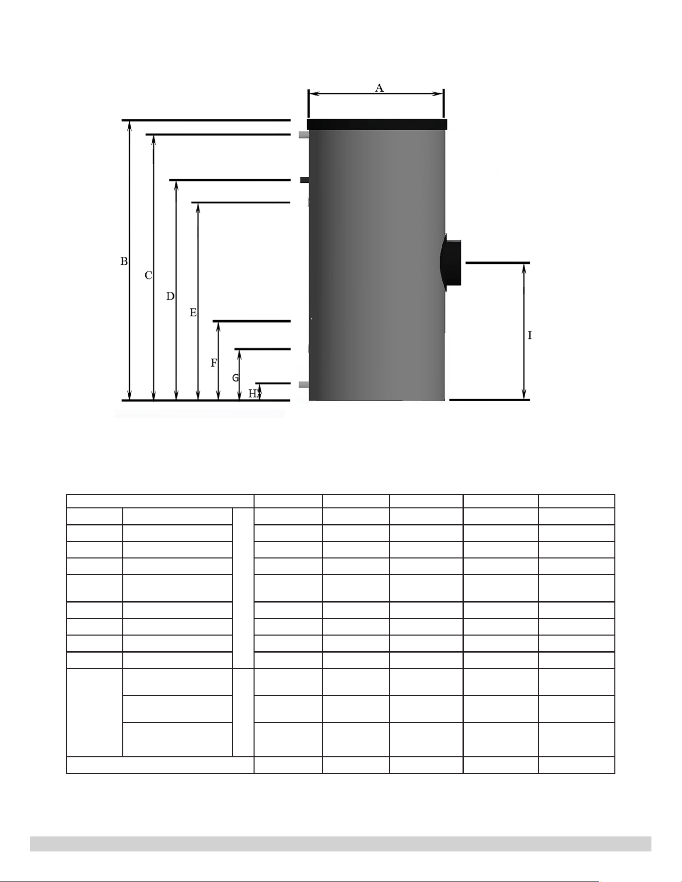
Figure 1. Front View
Table 1. Indirect Water Heater Dimensions
Dimensions H2O 30 GL H2O 40 GL H2O 50 GL H2O 80 GL H2O 105 GL
A
Insulated Diameter
Inch
24 24 24 30 30
B
Height
33 45 51 48 62
C
DHW Outlet
30 42 48 45 59
D
Coil Inlet
20 35 35 36.5 40
E
Service Circulation
Outlet
24 31 37 35 48
F
Aquastat Well
17 15 21 22 24
G
Coil Outlet
10 10 10 11 11
H
DHW Inlet
3 3
3
3.5 3.5
I
Service Cap
- 26 27 29 34
T h r e a d e d
Connections
DHW Water Inlet,
Outlet
NPT
1" 1" 1" 1" 1"
Service Circulation
Outlet
¾” ¾” ¾” ¾” ¾”
Boiler Coil Inlet,
Outlet
1" 1" 1" 1" 1"
Weight lbs.
119 180 200 243 393
8
PN 615000229 REV. G [10/01/2021]
Table 2. Parameters & Working Pressure Rating
Model
Storage
Volume
Coil Heating
Surface
Maximum Working
Pressure (psi)
Gallon ft
2
DHW
Water
Boiler
Water
H2O 30 GL 31 6.35 150 116
H2O 40 GL 42 14 150 116
H2O 50 GL 53 14 150 116
H2O 80 GL 79 20.7 150 116
H2O 105 GL 106 26 150 116
Table 3. Performance Rating
Model
First Hour
Draw
GPH
Continuous
Draw
GPH
Boiler
Output
Required
Boiler
Water
Flow
∆P
Through
Coil
140° F 115° F 140° F 115° F MBH GPM FT Water
H20 30 GL
102 116 80 93 75 14 7.5
H2O 40 GL
175 198 138 162 105 14 10.7
H2O 50 GL
187 212 144 169 110 14 10.7
H2O 80 GL
204 228 140 164 110 14 15.9
H2O 105 GL
244 270 149 175 115 14 19.7
Note: All ratings are based on 50° F cold DHW water inlet.
3. DHW Pump Sizing
Refer to Table 3 for minimum ow through the water heater coil and pressure drop at the required boiler water ow rate.
Calculate the pressure drop across all pipes and ttings connecting the indirect water heater and hot water boiler. Be sure
to include all ball valves, check valves, etc. It is manufacturer recommended that the indirect water heater loop be piped
with 1” pipe around the entire loop on typical residential sites.
4. System Zone Control
The water heater shall be installed as a separate zone from the space heating zones. If the indirect water heater pump
and space heating pump run at the same time (non-priority), the water heater zone’s piping and circulator must be sized
for the minimum ow rate with all the zones in use and maximum ow with only the water heater in use. The three most
common systems are:
• Central heating zone circulator and indirect tank circulator. Space heating zones use a circulator for each zone. The
water heater is controlled with an additional circulator (DHW pump).
• Central heating system circulator and indirect tank circulator. One heating system pump is used for all space
heating zones. Each heating zone has one zone valve. The indirect water heater is controlled with additional
indirect tank circulator.
• Central heating zone Valves and indirect tank zone valve. Space heating zones use zone valves for each zone. The
water heater is controlled with an additional zone valve. In such system, indirect tank shall use a low pressure drop
zone valve. Adequate boiler water ow through the indirect tank coil must be assured.

9
PN 615000229 REV. G [10/01/2021]
5. Priority or Non-Priority for Hot Water
Priority. The demand for space heating is interrupted until the hot water demand is satised or priority time is reached.
This option provides the reliable delivery of hot water. Priority is recommended when:
• Boiler output is less than 100,000 Btu per hour.
• Heating capacity required by the indirect tank is more than 50% of the heating capacity needed for space heating
demand.
• When an interruption in space heating can be tolerated during long domestic hot water draws.
In most cases the delay in space heating will not be noticed because of the rapid recovery of the indirect water heater. It
must be recognized however that certain water heater malfunctions, such as a failed thermostat or circulator, could delay
space heating indenitely, if priority time is not established.
Non-Priority. The boiler output is divided between space heating and the indirect water heater. Heating of domestic hot
water can be reduced during simultaneous space and water heating demands. The amount of reduction depends on boiler
output, number of space heating zones calling, and amount of boiler water ow split between space heating zones and
water heater zone.
6. Locating the Indirect Water Heater
NOTICE
All water heaters will eventually leak, which can cause property damage. Do not install indirect water heater
in a location that does not have adequate drainage.
• Locate water heater in an area not subject to freezing temperatures.
• Locate water heater in an area where water leakage from the tank or connections will not result in damage to areas
adjacent to the water heater or to lower oors of the structure. When such a location cannot be avoided, a suitable
drain pan shall be installed under the water heater, and the drain pan must be connected to a drain.
• The drain pan should be at least 2” deep with a length and width at least 2” greater than the total diameter of the
unit and should be piped to an adequate drain.
• Drain pans are available from your wholesale distributer.
• The life span of an indirect water heater depends on water quality, water pressure, and the environment in which
the water heater is installed.
• Water heaters are sometimes in locations where leakage may result in property damage, even when a drain pan
is installed and piped to a drain. Such property damage can be reduced or prevented by a leak detector or water
shut-o device used in conjunction with a piped drain pan. These devices, available from some plumbing supply
wholesalers and retailers, detect and react to leaks in various ways.
a. Sensors mounted in the drain pan that trigger an alarm or turn o the incoming water to the water heater when
leakage is detected.
b. Sensors mounted in the drain pan that turn o the water supply to the entire home when water is detected in
the drain pan.
c. Water supply shut-o devices that activate based on the water pressure dierential between the cold water and
hot water pipes connected to the water heater.
10
PN 615000229 REV. G [10/01/2021]
7. Minimum Clearance from Combustibles
0 inches on all Sides.
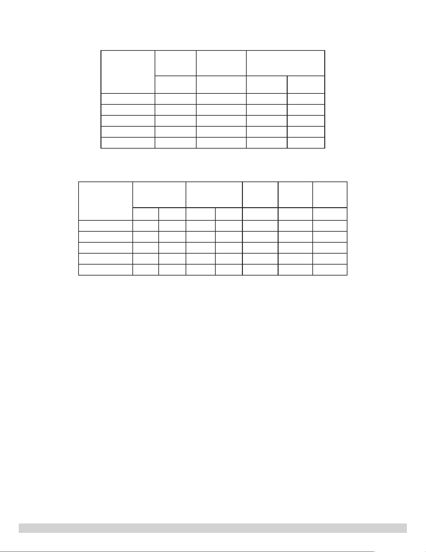
8. Minimum Service Clearance
Table 4. Minimum service clearance
Model H2O 30 GL H2O 40 GL H2O 50 GL H2O 80 GL H2O 105 GL
Pipe Connection Side
18”
Service cap Side
20”
Zipper Side
4”
Back Side
0”
Top
22” 43”
Figure 2. Top view
Service cap Side
Pipe
Connection
side
Zipper Side
Pipe
Connection
Side
Service Cap Side
Back

11
PN 615000229 REV. G [10/01/2021]
9. Additional Components
• Shut-o valves: Allows isolation of the water heater from boiler system during service.
• Dielectric Unions: Field supplied dielectric unions are required and designed to be installed between pipe made
from dissimilar metals to prevent accelerated corrosion and deterioration in the piping system due to stray current
discharges.
• Vacuum Breaker: Protects the water heater from collapse if a hot tank is shut o to service other components in
the system. Required for Commonwealth of Massachusetts.
• Thermal Expansion Tank: If the water heater is installed in a closed water supply system, such as a system
having a back ow preventer in the cold water supply line, installation of a thermal expansion tank is
required.
• Water Hammer Arrester: Dishwashers, clothes washers, and fast-closing positive shuto valves incorporated in
the system all contribute to creating water hammer. Install a water hammer arrester to prevent damage to pipes
and appliances. See water hammer arrester manufacturer’s instructions for application and installation.
• Backow Preventer: Protects potable water supplies from contamination due to backow. Requirements for
Commonwealth of Massachusetts. Boiler installation shall conform to the Commonwealth of Massachusetts code
248 CMR which includes but is not limited to: Installation by licensed plumber or gas tter.
10. Removing the Existing Domestic Water Heating System
• External Tankless Heaters - Disconnect all lines to the boiler and plug the boiler ttings. Disconnect the external
heater from the boiler piping and the domestic piping systems.
• Internal Tankless Heaters - Disconnect the domestic piping. Do not plug the cold water or the hot water ttings
in the internal tankless coil. Leave the coil in the boiler with cold and hot water ttings open to prevent pressure
build-up in the coil.
NOTICE
For California installation this water heater must be braced, anchored, or strapped to avoid falling or moving
during an earthquake. See instructions for correct installation procedures. Instructions may be obtained from
California Oce of the State Architect.
11. Water Quality
Improper water quality will reduce the expected life of the water heater. Hard water, sediment, high or low PH value,
and high levels of chlorides in the domestic water should be avoided. Sediment and hard water will eventually coat the
heating coil inside the water heater and reduce the rate of hot water production and may, eventually, cause a failure.
High or low PH and/or chloride concentrations will cause corrosion and eventually failure. A lter is strongly manufacturer
recommended where sediment is present in the water. A water softening system is recommended for areas with hard
water. In an area where the water quality is unknown, a water quality test should be performed, and the water condition
treated.
12
PN 615000229 REV. G [10/01/2021]
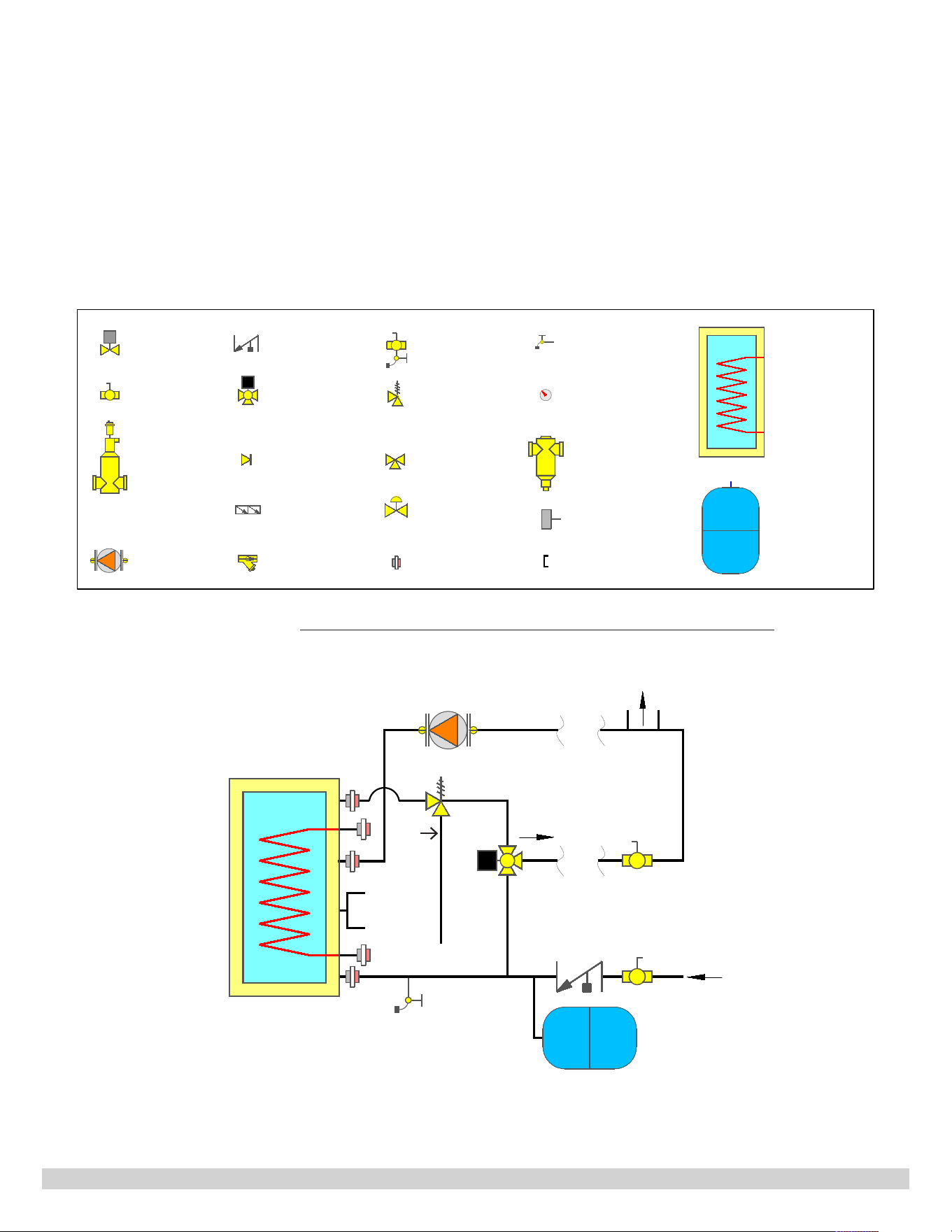
Figure 3 - Illustrates the connection of the DHW hot water recirculation loop. The recirculation of DHW hot water
can reduce the waiting time of how water at faucets or shower heads. All models have the DHW service recirculation
connection. DHW service recirculation pump, such as Taco SmartPlus
®
recirculation pump, must be eld sourced and
installed. The recirculation loop is not totally shown in all the other piping gures for simplicity.
To accurately sense water temperature, the pressure temperature relief valve shall be a maximum of 8” away from the
water heater, as shown in Figure 3. Do Not install any valve between the tank and pressure relief valve.
Figure 3. Tank Connections And DHW Service Recirculation Pump
III. PIPING
1. Piping Diagrams
All the piping instructions and Figures, presented in this document, are for schematic illustration purposes and focus on
how boiler water and DHW ow. Not all components are shown for the heating system, such as air remover, check valve,
automatic feeder, etc.
Pipe lengths (except explicitly stated) and orientation of the elbows and tees do not have to be exactly the same as show
in the Figures. They should be determined by the actual conditions, layout, and space limitation of the installation. In all
piping Figures, the connections and components are labeled as shown in Table 5.
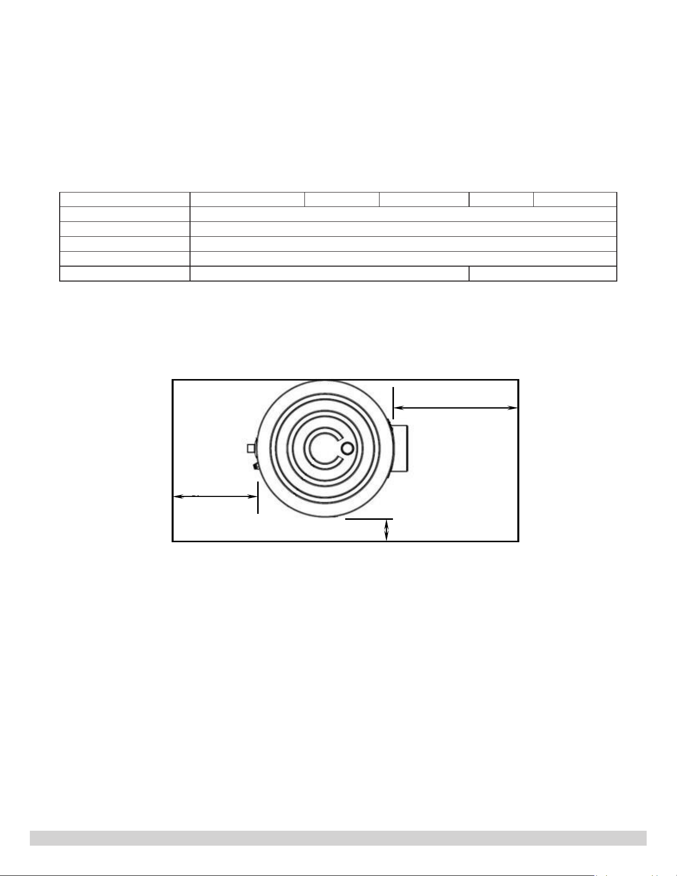
Table 5. Piping Legend
T
T
TO FIXTURES
HOT WATER
SUPPLY
TEMPERED
COLD WATER
SUPPLY
<6"
ABOVE
GROUND
Zone Valve
Ball Valve
Air Seperator
Circulator with
Isolation Valves
Flow Check Valve
Thermostatic
Mixing Valve
Temperature
Pressure Reiief
Valve
Purging Valve
Pressure Reducing
Valve
Bypass Valve
Back Flow Preventor
Diverter Valve
Strainer
Dielectric Union
Drain
Temperature &
Pressure Guage
Magnetic Dirt
Separator
Indirect Tank
Aquastat
Cap
Indirect Water
Heater
Diaphragm - type
Expansion Tank
Piping Symbol Legend
13
PN 615000229 REV. G [10/01/2021]
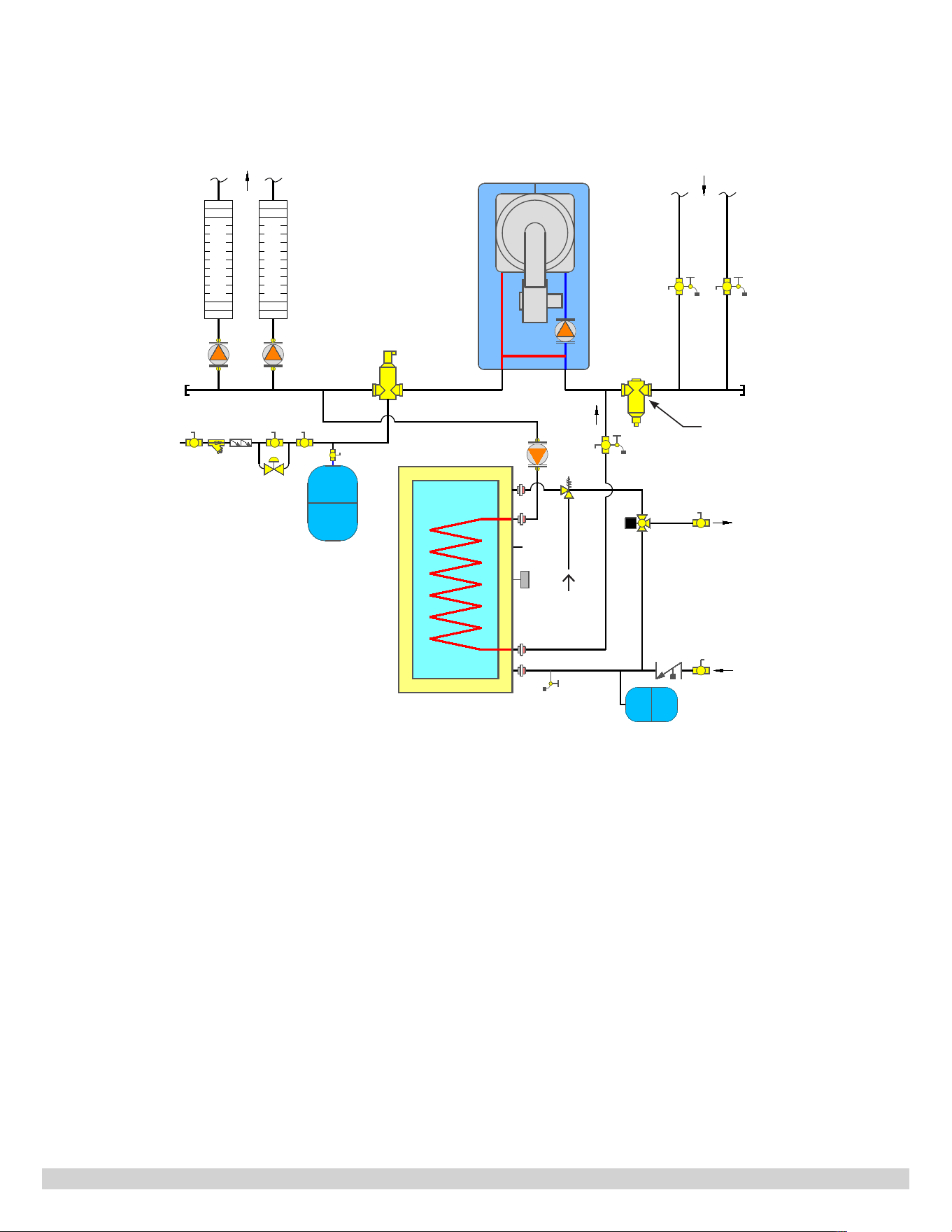
Figure 4. Piping Diagram Of The Tank For Boilers With Internal Primary Loop and Pump
Figure 4 -
Illustrates piping connections for boilers having no internal primary loop and no internal pump. Applicable
boilers include Cast Iron hot water boilers, Cast Aluminum hot water boilers, and boilers not requiring primary
secondary piping.
For boilers without an internal primary loop, but have an internal pump, the primary loop pump may not be needed.
This depends on the size of the internal pump and total length of the external primary loop. Refer to the boiler
Installation, Operation and Maintenance Manual (IOM) for detailed instructions.
Heating Load
Heating Load
T
T
HOT WATER
SUPPLY
TEMPERED
MAGNETIC DIRT
SEPARATOR
TO SYSTEM
COLD
WATER
SUPPLY
Z3 Z2
Z1
DHW PUMP
*
*
Recirculation Line
FROM SYSTEM
COLD WATER
SUPPLY
<6"
ABOVE
GROUND
14
PN 615000229 REV. G [10/01/2021]
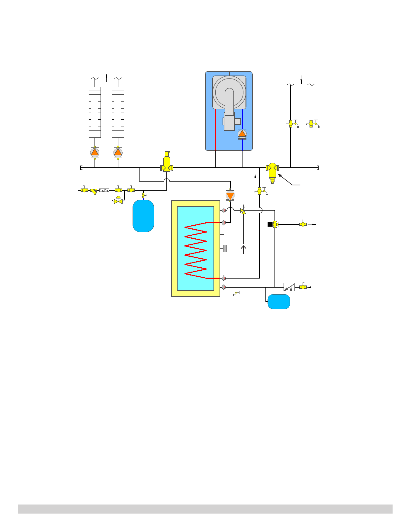
Figure 5. Piping Diagram With External Primary Loop For Boilers Without Internal 3-Way Valve or
Not Using The 3-Way Valve On The System
Figure 5 -
Illustrates piping connection of the tank with boilers that have external primary loop and internal pump.
The internal ball valve on the internal primary loop should be in an open position, so the internal primary loop is
established. This piping diagram also works for boilers that do not require primary secondary piping, such as cast iron
hot water boilers.
Heating Load
Heating Load
T
T
HOT WATER
SUPPLY
TEMPERED
MAGNETIC DIRT
SEPARATOR
TO SYSTEM
COLD
WATER
SUPPLY
Z3 Z2
Z1
DHW PUMP
*
<6"
ABOVE
GROUND
*
Recirculation Line
FROM SYSTEM
COLD WATER
SUPPLY
15
PN 615000229 REV. G [10/01/2021]
Zone pump conguration for central heating is shown in Figures 4 through 6. A CH system pump and zone valve
conguration is also acceptable, with one CH system pump on the supply header. The zone valve opens or shuts o the
boiler water ow for each of the central heating zones.
2. Install Pipes And Components
Follow piping installation instructions as shown in this manual with the piping guidance as given in the appropriate hot
water boiler Installation, Operation manual.
Quality installation and leak free connections threaded or soldered, are the responsibility of the professional installer who
carries out the work.
For all threaded connections, manufacturer recommends applying Teon tape and pipe dope. Teon tape must be applied
following the direction of the thread. The edge of the Teon tape shall not go beyond the end of the thread. The pipe
dope shall not go beyond the edge of the Teon tape.
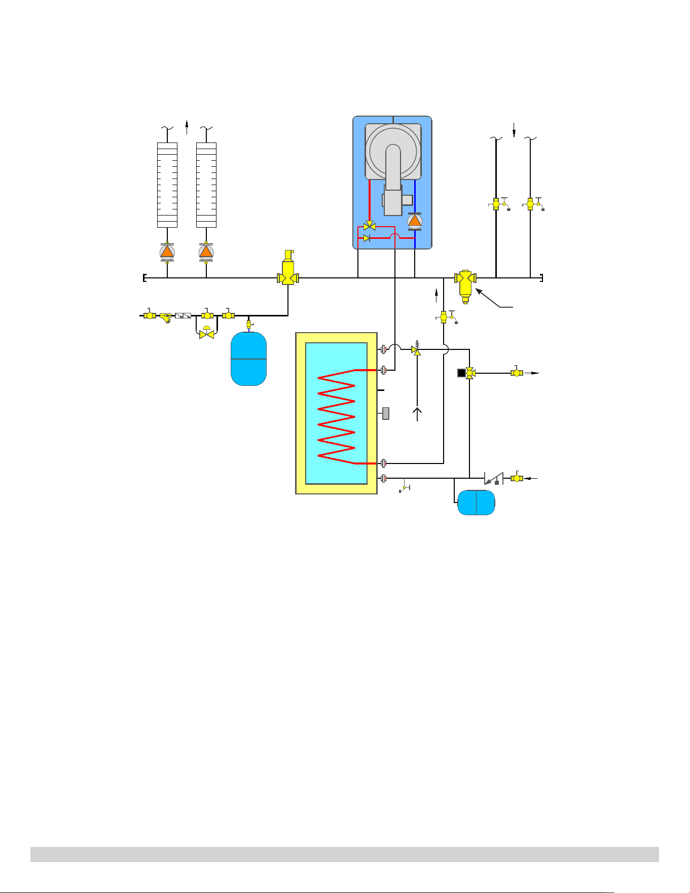
Figure 6. Piping Diagram Of The Tank For Boilers With Internal Pump And Three-Way Valve
Figure 6 -
Piping diagram of the indirect tank with boiler that has internal pump and three-way valve. Boiler working
in central heating mode, the three-way valve will send hot boiler water to CH supply. In DHW mode, the three-way
valve diverts all boiler water to an indirect tank supply.
Heating Load
Heating Load
T
T
COLD WATER
SUPPLY
HOT WATER
SUPPLY
TEMPERED
MAGNETIC DIRT
SEPARATOR
COLD
WATER
SUPPLY
Z3 Z2
*
<6"
ABOVE
GROUND
* Recirculation Line
FROM SYSTEMTO SYSTEM

16
PN 615000229 REV. G [10/01/2021]
3. DHW Water Pipe Installation
Install the DHW water piping and components per the following procedure:
• Shut o the cold water supply at the main shuto valve.
• Open one or more faucets to relieve the pressure. Open the system drain, leave faucets open.
• Drain the domestic water system.
• Install piping and ttings, connecting the tank cold water inlet and cold water supply of the residence, using
a dielectric union, heat trap, shut-o valve, vacuum breaker, expansion tank (where required), and lter
(manufacturer recommended to prevent sediment buildup).
• Connect the tank DHW hot water supply piping. Install piping to hot DHW hot water supply connection using a
dielectric union, heat trap, vacuum breaker, and shut-o valve.
• Install Pressure Temperature Relief Valve. Pipe the relief valve discharge so the discharge from the valve exits only
within 6 inches above, or at any distance below, the structural oor. Any discharged water for the indirect water
heater shall not contact any live electrical part. The discharge opening must not be blocked or reduced in size under
any circumstances. DO NOT install any valve between the tank and Pressure Temperature Relief Valve.
• The Pressure and Temperature Relief Valve shall be installed a maximum of 8” away from the tank on the DHW
Outlet connection. Placing Pressure Temperature Relief Valve to close to the tank during installation could cause
damage to the tank due to soldering. See Figure 3.
• Fill the water heater tank. Open all faucets to allow air to purge from the tank and piping. Remove screens on
faucets. Open domestic hot water shut-o valve. Open cold water inlet shut-o valve. Purge all air from the
domestic water system. Allow water to run so the tank is completely purged of any debris. Run the water long
enough to change at least ve tank volume changes. Close all faucets. Reinstall all of the screens in the faucets.
Check the system for leaks. Repair as required.
NOTICE
If installing on a city supply, a properly sized thermal expansion tank is required and installed in accordance
with the product manufacturer's installation manual. If a water heater is installed in a closed water supply
system, such as one having a backow preventer in the cold water supply, a check valve in the cold water
supply, or a pressure reducing valve in the cold water supply provide a means to control thermal expansion.
The appliance, when installed, must be grounded in accordance with the local codes, or in the absence of local
codes, with the National Electrical Code, ANSI/NFPA 70.
If this product is connected to a cold water supply line that has a check valve, a backow preventer, a pressure reducing
valve, or a water meter with a built in check valve, it is a requirement that a properly sized thermal expansion tank be
installed in the cold water inlet line.

17
PN 615000229 REV. G [10/01/2021]
Temperature Pressure Relief Valve Installation:
• Install discharge line so water discharged from the temperature and pressure relief valve exits within 6" six inches
above, or any distance below, the structural oor.
• Install temperature Pressure valve so discharge shall not contact any live electrical part.
• Install temperature pressure valve as shown in Figure 13.
• Do not install a valve or shuto device between tank and temperature pressure valve.
• Install discharge line to allow for complete drainage of both temperature pressure relief valve and the discharge
line.
• Discharge opening must not be subjected to blockage or freezing.
• Size and arrange discharge piping to avoid reducing Temperature Pressure Valve relieving capacity below minimum
relief valve capacity.
• Run pipe as short and straight as possible to location protecting user from scalding and properly drain piping.
• Terminate pipe with plain end (not threaded).
• Do not thread, plug, or cap discharge line.
• Maintain minimum clearance of four (4) inches on side of water heater for servicing and maintenance of
temperature pressure valve
4. Boiler Water Pipe Installation
Installation procedure for pipes and components for boiler water ow.
1.
Determine where the boiler, space heating, and water heater connections should be made based on the type of piping
system that is either in-place or is to be installed for a new hydronic system installation.
2.
It is manufacturer recommended that 1”, or larger, pipe be installed for boiler between indirect tank and the hot water
boiler. If boiler water through the indirect tank coil is controlled by a zone valve, a 1” zone valve is recommended.
3.
Central Heating Zone Pump System. For a system using central heating zone pumps, the water heater connection
labeled “BOILER SUPPLY” should be piped to the boiler supply piping after the air eliminator and before the space
heating takeos. Mount the water heater circulator as close as possible to the water heater, and make sure the ow
arrow points toward the water heater. The use of shut-o valves is recommended for future service convenience. The
water heater connection labeled “BOILER RETURN” should be piped to the boiler return piping as close to the boiler
as possible and after any ow control or check valves in the space heating return piping. The use of a union and a
shut-o valve is manufacturer recommended. Use of a check valve is required to prevent back ow through the water
heater during operation of the space heating system.
4.
Central Heating Zone Valve System. For a space heating system that uses Zone Valves, refer to Figure 4. Replace
zone circulators with valves. The water heater connection labeled “BOILER SUPPLY” should be piped to the boiler
supply piping after the air eliminator and before the Central Heating system pump. Mount the water heater circulator
as close as possible to the water heater, and make sure the ow arrow points toward the water heater. The use of a
shut-o valve is recommended for future service convenience. The water heater connection labeled “BOILER RETURN”
should be piped to the boiler return piping as close to the boiler as possible and after any ow control or check valves
in the space heating return piping. The use of a union and a shut-o valve is recommended. The use of a check valve
is required to prevent back ow through the indirect water heater during operation of the space heating.
NOTICE
When installing pipes and ttings on the threaded connections on the indirect water heater, all soldered
joints shall be a minimum of four inches away from the indirect water heater to provide enough room for the
soldering process. Any damages on the tank cover and insulation material are not covered by warranty.
WARNING
Burn and Scald Hazard. Temperature pressure relief valve could discharge steam or hot water during
operation. Install discharge piping per the instructions given below.
!
18
PN 615000229 REV. G [10/01/2021]
IV. ELECTRICAL WIRING
If a heating system is small and the installed boiler oers a terminal to power a central heating system pump and DHW
pump, the complete heating system can be controlled by the integrated boiler control built inside the boiler. When using
this type of wiring conguration, the power draw of the central heating pump and DHW pump must not exceed the amp
draw allowed by the boiler integrated control. Refer to the boiler Installation, Operation and Maintenance Manual for
detailed information.
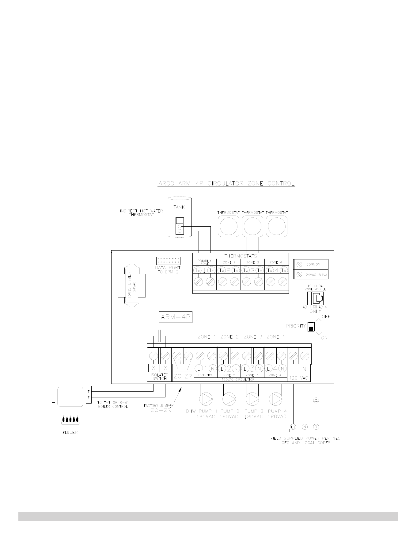
For heating systems that need zone control device(s), Argo Controls oer a broad line of control devices for hot water
heating systems, including the ARM-4P and Argo Universal Zone Control. More information is available at http://
argoindustries.com.
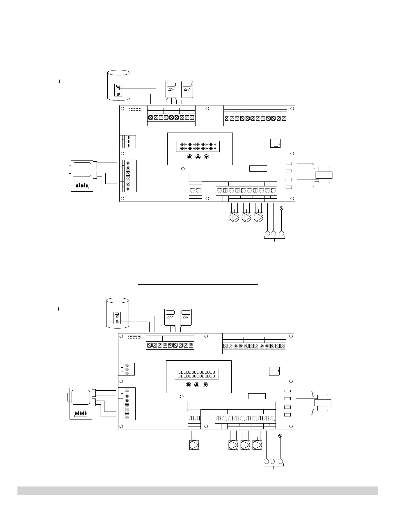
Figure 7. Wiring Diagram For Boilers That Do Not Dierentiate Call For CH And Call For DHW
19
PN 615000229 REV. G [10/01/2021]
Figure 8. Wiring Diagram For Boilers That Do Not Require Primary/Secondary Piping Or Boilers
With Internal Primary Loop And Pump
Figure 9. Wiring Diagram For Boilers Piped With External Primary Loop
C
NETWORK
SCL SDA
ZONE 1
LINE
24V
Vac
L
C
R
115 Vac
N
115
COM
Vac
ZRZC
115 Vac
N
L
1
L
N
ZONE PUMPS
32
1
X
NEC Class 2 Low Voltage
ZONE 1
R
T
THERMOSTATS
ZONE VALVES
ZONE 3ZONE 2
1
NEC Class 2 Low Voltage (24Vac)
PRIMARY
ZC/ZR
D
W
H
BOILER
T
T
CH
DIGITAL LCD USER DISPLAY
EXPANSION
PORT
MODE UP DOWN
23412341234
W
TC
R
T
W
TC
R
T
W
TC
ZONE 2 ZONE 3
NEC Class 2 Low Voltage (24Vac)
2
L
N
3
L
N
GND
G
G
G
1
L
N
PUMP
XXXXX
DPM2
L N
G
FIELD SUPPLIED POWER PER NEC,
CEC
AND
LOCAL
CODES
TRANSFORMER
DHW
ZONE THERMOSTATS
I
NDIRECT HOT WATER
THERMOSTAT
DATA PORT
ISOLATED END SWITCH X-X
ARGO
UZ3
U
N
IVERSA
L
ZO
N
E
CO
N
T
RO
L
Fuse 12A
Z2 Z3
TANK
C
NETWORK
SCL SDA
ZONE 1
LINE
24V
Vac
L
C
R
115 Vac
N
115
COM
Vac
ZRZC
115 Vac
N
L
1
L
N
ZONE PUMPS
32
1
X
NEC Class 2 Low Voltage
ZONE 1
R
T
THERMOSTATS
ZONE VALVES
ZONE 3ZONE 2
1
NEC Class 2 Low Voltage (24Vac)
PRIMARY
ZC/ZR
D
W
H
BOILER
T
T
CH
DIGITAL LCD USER DISPLAY
EXPANSION
PORT
MODE UP DOWN
23412341234
W
TC
R
T
W
TC
R
T
W
TC
ZONE 2 ZONE 3
NEC Class 2 Low Voltage (24Vac)
2
L
N
3
L
N
GND
G
G
G
1
L
N
PUMP
XXXXX
DPM2
L N
G
FIELD SUPPLIED POWER PER NEC,
CEC
AND
LOCAL
CODES
TRANSFORMER
DHW
ZONE THERMOSTATS
I
NDIRECT HOT WATER
THERMOSTAT
DATA PORT
ISOLATED END SWITCH X-X
ARGO
UZ3
U
N
IVERSA
L
ZO
N
E
CO
N
T
RO
L
Fuse 12A
Z2 Z3
G
PRIMARY
TANK
20
PN 615000229 REV. G [10/01/2021]
Figure 7 Wiring diagram for boilers that do not dierentiate CH call and DHW call. The boiler has only one temperature
setting for both CH call and DHW call. For such boiler, primary secondary piping may not be required.
Figure 8 Wiring diagram for boilers that have dierent temperature settings for a CH call and DHW call. Boilers can be
those that do not require primary secondary piping, or a primary loop/pump built inside the boiler.
Figure 9 Wiring diagram for boilers piped with external primary loop. The primary loop pump can be powered by the
Argo zone control board. It may can be powered by the boiler integrated control, if primary pump terminals are available.
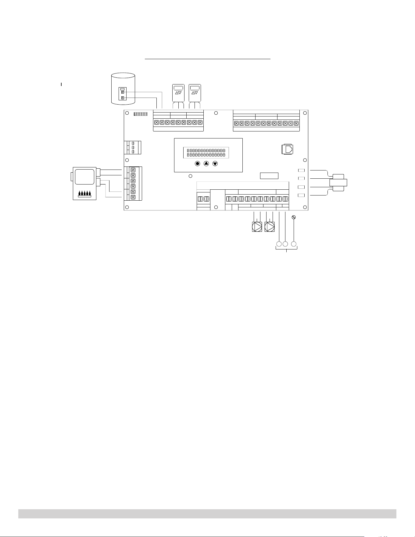
Figure 10 Wiring diagram for boilers with internal pump and a three-way valve. For such boilers, no DHW pump is
needed.
For boilers that can take Indirect Tank Temperature signal, a tank temperature sensor (normally supplied by the boiler
manufacturer) can be inserted into the Aquastat well. The temperature signal is directly supplied into the boiler control
board. Therefore, the Aquastat supplied with the indirect tank will not be used.
Install electric wiring and grounding in accordance with the National Electrical code and local regulations. (Refer to wiring
diagrams given in the documentations of pumps, boilers, Argo controls, etc. for more information.)
Figure 10. Wiring Diagram For Boilers With Internal Pump And A Three-Way Valve
C
NETWORK
SCL SDA
ZONE 1
LINE
24V
Vac
L
C
R
115 Vac
N
115
COM
Vac
ZRZC
115 Vac
N
L
1
L
N
ZONE PUMPS
32
1
X
NEC Class 2 Low Voltage
ZONE 1
R
T
THERMOSTATS
ZONE VALVES
ZONE 3ZONE 2
1
NEC Class 2 Low Voltage (24Vac)
PRIMARY
ZC/ZR
D
W
H
BOILER
T
T
CH
DIGITAL LCD USER DISPLAY
EXPANSION
PORT
MODE UP DOWN
23412341234
W
TC
R
T
W
TC
R
T
W
TC
ZONE 2 ZONE 3
NEC Class 2 Low Voltage (24Vac)
2
L
N
3
L
N
GND
G
G
1
L
N
PUMP
XXXXX
DPM2
L N
G
FIELD SUPPLIED POWER PER NEC,
CEC
AND
LOCAL
CODES
TRANSFORMER
ZONE THERMOSTATS
I
NDIRECT HOT WATER
THERMOSTAT
DATA PORT
ISOLATED END SWITCH X-X
ARGO
UZ3
U
N
IVERSA
L
ZO
N
E
CO
N
T
RO
L
Fuse 12A
Z2 Z3
TANK
21
PN 615000229 REV. G [10/01/2021]
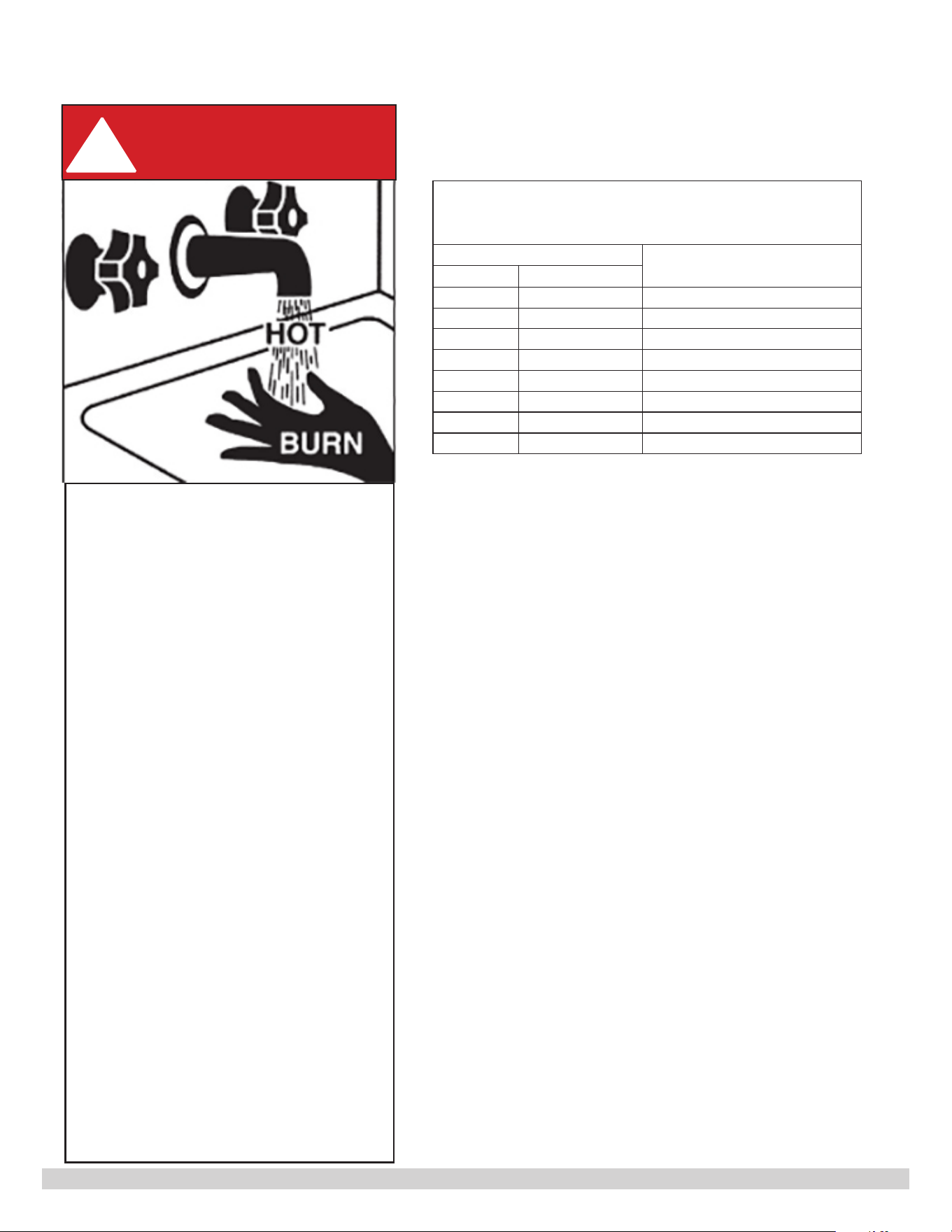
Approximate Time/Temperature
Relationships in Scalds
Hot Water Temperature
Time for scald injury
°F °C
120 49 More than 5 Minutes
125 52 1½ to 2 Minutes
130 54 About 30 Seconds
135 57 About 10 Seconds
140 60 Less Than 5 Seconds
145 63 Less Than 3 Seconds
150 66 About 1½ Seconds
155 68 About 1 Second
Hot Water Can Scald!
Water heated to temperature for clothes
washing, dish washing and other
sanitizing needs can scald and cause
permanent injury.
Children, elderly, and inrm or physically
handicapped persons are more likely to
be permanently injured by hot water.
Never leave them unattended in bathtub
or shower. Never allow small children to
use a hot water tap or draw their own
bath.
If anyone using hot water in the building
ts the above description, or if state
laws or local codes require certain water
temperatures at hot water taps, you
must take special precautions:
• Use lowest possible temperature setting.
•
Install some type of tempering device, such
as an automatic mixing valve, at hot water
tap or water heater. Automatic mixing valve
must be selected and installed according
to manufacturer's recommendations and
instructions.
Water passing out of drain valves may be
extremely hot. To avoid injury:
• Make sure all connections are tight.
• Direct water ow away from any
person.
DANGER
!
Table 6: Hot Water Temperature and Time to Scald
Injury
V. OPERATION

22
PN 615000229 REV. G [10/01/2021]
2. Temperature Adjustment
The tank thermostat controls the maximum water temperature in the water heater. If it is set too high, the resulting hot
water can cause painful scalding with possible serious and permanent injury. The temperature at which this occurs varies
with a person’s age, and the length of time in contact with the hot water. The slower response time of infants, older, or
handicapped people increase the hazard for them.
Manufacturer recommends setting the Aquastat for the lowest possible temperature that satises your needs. This will
provide the lowest energy consumption and cost.
Check the water temperature at a hot water faucet soon after the tank thermostat has satised, and the circulator and the
boiler have turned o. Adjust as needed.
Lowering the thermostat setting will not have an immediate eect on the water temperature because stored water will be
used and the thermostat must go through the cycle of heating cold water and satisfying at the new, lower temperature.
Additional temperature checks should follow the completion of a heating cycle. Further adjustments may be required after
you have use the water heater.
Lowering the thermostat setting will not have an immediate eect on the water temperature because the stored water
will have to be used and the thermostat must go through the cycle of heating cold water and satisfying at the new, lower
temperature. Additional temperature checks should follow the completion of a heating cycle. Further adjustments may be
required after use of the water heater.
Table 6 details the approximate relationship of water temperature and time with regard to scald injury and may be used
as a guide in determining the safest water temperature for your applications.
The scald label can be found on all Indirect Water Heaters and Storage Tanks. Take note and use caution when adjusting
the temperature settings with your water system. Be sure to always feel the water before bathing or showering, especially
when drawing a bath for an infant, elder or handicapped person.
1. Startup
DANGER
Burn, scald hazard. This water heater can deliver scalding temperature water at any faucet in the system. Be
careful when using hot water to avoid scalding injury. By setting the Aquastat on this water heater to obtain
an increased water temperature, you create the potential for scald injury.
!
To protect against injury, install an ASSE approved mixing valve (a device to limit the temperature of water to protect
against scald injury via mixing hot and cold water supply) in the water system. This valve will reduce point of discharge
temperature in branch supply lines. Consult with a plumbing professional.
After the water heater has been piped and wired and boiler water piping is purged of air, the water heater is ready to be
started.
• Follow boiler installation instructions to place the boiler in operation.
• The tank Aquastat is factory pre-set to 125° F and will call for heat if the water in the tank is lower than 125° F.
• When the indirect tank is calling for heat, the tank thermostat contacts close and send a call for DHW signal to the
boiler indirectly or through the Control. Such signal will start the DHW pump and the boiler.
• After the tank has reached the temperature setting, the tank Aquastat opens and de-energizes the DHW pump and the
boiler.
23
PN 615000229 REV. G [10/01/2021]
WARNING
Burn and Scald Hazard! Temperature pressure relief valve could discharge steam or hot water during
operation.
!
VI. MAINTENANCE
The water heater is intended to provide many years of reliable service. Components, such as thermostats, anode rods,
and pressure temperature relief valves, may be subject to failures that require service. Depending on the quality of the
water supply, sediment and/or scale may coat the heating coil in the tank and reduce hot water recovery rate. Failure to
use the correct procedures or parts can result in unsafe operation. For more details on the Anode Rod see Section VI-2.
1. Inspections
Arrange to have the following inspections and simple maintenance procedures done at the suggested frequencies.
• Check boiler piping and domestic water piping annually. Check for any signs of leakage at all the joints, unions and
shut-o valves. Repair as required.
• Check temperature pressure relief valve annually. The temperature pressure relief valve should be checked to
ensure that it is in operating condition. To check the relief valve, lift the lever at the end of the valve several times.
The valve should seat properly and operate freely. If the water does not ow, remove and inspect for obstructions
or corrosion. Replace with a new valve of the recommended capacity as necessary. Do not attempt to repair the
valve, as this could result in improper operation and a tank explosion. In areas with poor water conditions, it may be
necessary to inspect the pressure temperature relief valve more often than once a year.
• Check for sediment build up annually except where harsh water quality may require more frequent service.
Depending on water conditions, a varying amount of sediment may collect in the tank. Levels requiring service are
indicated by a small temperature dierence between the boiler supply and return lines, and a reduced recovery rate.
Repeated ushing usually clears such material. As a preventive measure, water should be drawn from the drain
valve until it runs clear and the installation of a water lter should be considered.
• Annually check for hard water which may cause scale buildup on the outside of the heating coil inside the tank.
A water softener will prevent buildup. Symptoms are identical to sediment buildup. If repeated ushing does not
resolve:
1. Remove service cap to gain access to tank interior and heating coil. Wash down inside of the DHW tank and
heating coil with cold water. Use a wet & dry vacuum with plastic hose to remove sediment from tank.
2. Chemical cleaning may be required. Contact a qualied contractor.
Before manually operating the temperature pressure relief valve, verify a drain line has been attached to the valve
to direct the discharge to an open drain. Failure to take this precaution could mean contact with extremely hot water
discharging from the valve during this checking operation. If the temperature pressure relief valve on the heater
discharges periodically or continuously, it may be due to thermal expansion of water in a closed water supply system, or
it may be due to a faulty relief valve. Thermal expansion is the normal response or water when it is heated. In a closed
system, thermal expansion will cause the system pressure to build until the relief valv
e actuation pressure is equaled.
Then the relief valve will open, allowing some water to escape, slightly lowering the pressure. Contact your water supplier
or local plumbing inspector on how to control the situation.
24
PN 615000229 REV. G [10/01/2021]
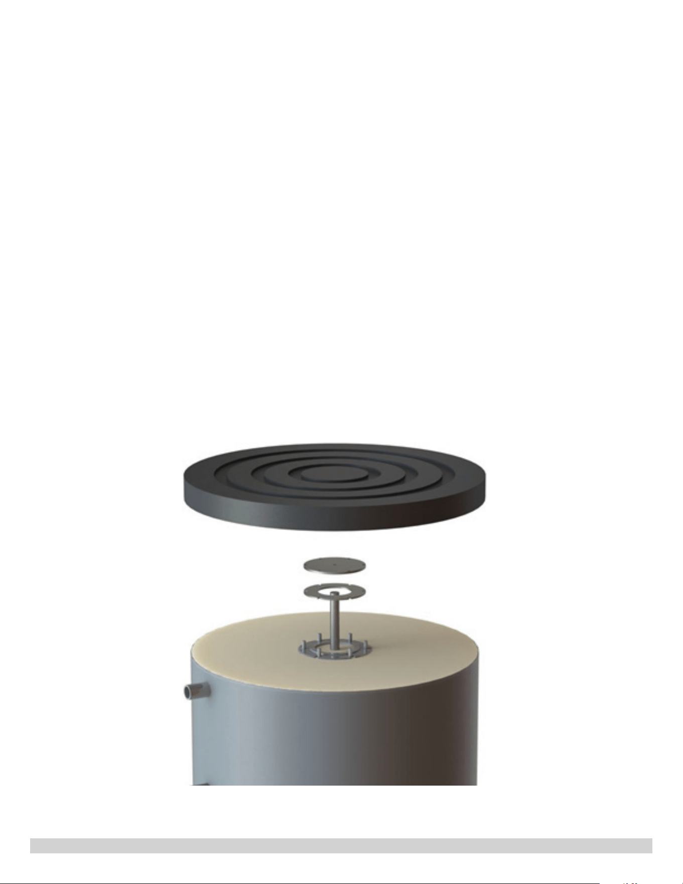
2. Inspect Anode Rod, Annually
The purpose of the anode rod is to reduce the damaging eects of aggressive water on the water heater. Aggressive water
will cause the anode(s) to erode. The anode(s) shall be inspected at least annually to determine whether a new anode
should be installed. Use anode replacement parts (see Table 7) supplied by ECR only. ECR anodes are 1-1/4” NPT and
are made with magnesium, brass, and stainless steel. There is no steel in an ECR anode. Severe or rapid deterioration
of the anode indicates very aggressive water. If this occurs, have the water tested to verify whether it is within the limits
outlined on page 11. Failure to inspect the anode and replace, if necessary, could result in damage to the water heater. If
this unit is installed and maintained according to the instructions and conditions in this manual, this product will last for a
long time. Refer to Figure 12 for the following procedure.
• Close domestic water isolation valves.
• Drain the water heater completely and allow it to cool.
• Remove the anode cover on the top of the unit.
• After the water heater has drained and cooled, remove the insulation, screws, and washers from the ange.
• Inspect the gasket and replace if necessary.
• Remove the anode and replace if needed. The anode should be replaced when more than 6” of core wire is
exposed. Replace the anode with an ECR supplied anode only. See replacement parts list.
• Assemble anode, gasket, ange and screws into the assembly.
• Rell the water heater, and restore operation.
• Verify operation of boiler and water heater.
Figure 12. Anode Rod Inspection

25
PN 615000229 REV. G [10/01/2021]
VII. TROUBLESHOOTING
PROBLEM CAUSE SOLUTION
No hot water at faucets
Boiler does not operate.
Press reset button
Check main cut-o switch Check fuses or breakers.
Check power supply Check shaft coupling
Circulator does not operate Check tank coupling
Improper thermostat setting Turn thermostat to higher setting.
Zone valve does not open Check power supply and valve
Electrical problem
Check fuses and replace. Check circuit breaker and
reset. Check power supply
Sediment and/or scale buildup
If boiler, circulator, and thermostat are operating
properly, and boiler is cycling on high limit several times
before the tank thermostat is satised, the coil may
have a coating of sediment and/or scale.
Clogged lter Clean or replace lter.
Insucient or runs out of
hot water at the faucet
Thermostat setting too low. Turn thermostat to higher setting.
Under sized boiler with no priority
to domestic water heating.
Rewire for priority.
Peak draw of hot water is greater
than tank storage.
Determine peak usage and compare to tank volume.
Sediment and/or scale buildup Clean coil
Faulty water heater thermostat Replace thermostat
Water at faucet too hot
Thermostat set to high Lower thermostat setting.
Improper system plumbing
Compare plumbing to installation guide. Inspect check
valves.
Improper wiring. Compare wiring to installation guide.
Boiler cycles more than 5
times per day in summer
Excessive demand
Reduce demand or consider larger boiler and/or water
heater.
Faulty thermostat Replace thermostat
Boiler high limit set to low Increase boiler hi-limit setting
Sediment and or scale buildup Clean coil
26
PN 615000229 REV. G [10/01/2021]
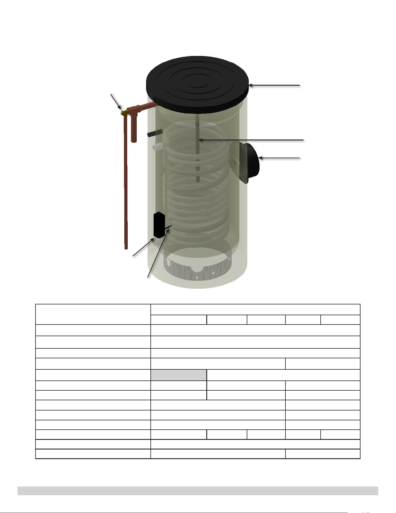
Figure 13. Indirect Water Heater Internal Structure
Table 7. Replacement Parts
Description
Model
30 Gal 40 Gal 50 Gal 80 Gal 105 Gal
Temperature and Pressure Relief Valve 240010926
Aquastat Well AQ-020.01
Aquastat 240013432
Top Cap 240012211 240012239
Service Cap Not Available 240012212
*Anode Kit Magnesium 550003640 550003505 550003527
*Anode Kit Aluminum 550003693 550003694 550003695
Flange Cap 240012250 240012251
Flange Gasket 240012210 240012238
**Hardware Kit 550003510 550003525
Outside Tank Cover 240012474 240012329 240012330 240012331 240012332
Outside Tank Cover - Patch Kit 240012462
Temperature Gauge 240012483 240012484
* Anode Kit includes: Anode, Gasket and Bushing
** Hardware Kit includes: Bolts and nuts for ange cap
Top Cap
Service Cap
T/P Relief Valve
Anode Rod
Aquastat
Aquastat
Well

27
PN 615000229 REV. G [10/01/2021]
VIII. CRITICAL CHECK POINTS AFTER INSTALLATION
Critical Check Points Conrm
1 All pipes, ttings, soldered joints, threaded connections, etc., are leak free.
2 There are no ammables in vicinity of the installation.
3 There are no combustible materials inside the specied clearances.
4 There is enough drainage at the location of installation.
5
Discharge of pressure temperature relief valve is piped to no more than 6 inches
above the oor.
6 Pressure temperature relief valve is no more than 8 inches away from the tank.
7 Conrm operation of pressure temperature relief, verify it is not stuck closed.
8 All air in the indirect water heater is purged out of the tank.
9 All air in the hot water boiler system is purged out.
10 All pipes are well supported and hold in place.
11 Temperature setting on the Aquastat is proper for the application.
12 Mixing valve setting is proper for the application.
13 Water temperatures at faucets and shower heads are proper.
14 If installed, DHW service re-circulation pump setting is proper.
15
If an indirect water heater temperature sensor is used, instead of the Aquastat,
conrm the sensor is inserted all the way to the bottom of the Aquastat well.
Ensure the sensor wire between the tank and the boiler is held securely in-place.
16 If local regulation requires back ow preventer, conrm it is installed.
17
If back ow preventer is installed, conrm thermal expansion tank is installed for
DHW water.
18
Verify dielectric unions have been installed on the piping connections at the
Indirect water heater.

Installer Name (print)
Installer signature
Date (mm / dd / yyyy)
Model
S/N
All specications subject to change without notice.
©2021 ECR International, Inc.
2201 Dwyer Avenue, Utica, NY 13501
Tel. 800 325 5479
www.ecrinternational.com