Manufactured by:
ECR International Inc.
2201 Dwyer Avenue, Utica, NY 13501
Tel. 800 325-5479
www.ecrinternational.com
PN 240013340 REV. C [12/02/2022]
Models
15C-8D
15C-9D
15C
GAS-FIRED
HOT WATER BOILERS
INSTALLATION, OPERATION &
MAINTENANCE MANUAL
C.S.A. Certied for
Natural gas or
Propane
Tested for 50 psi.
ASME Working
Pressure
2
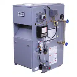
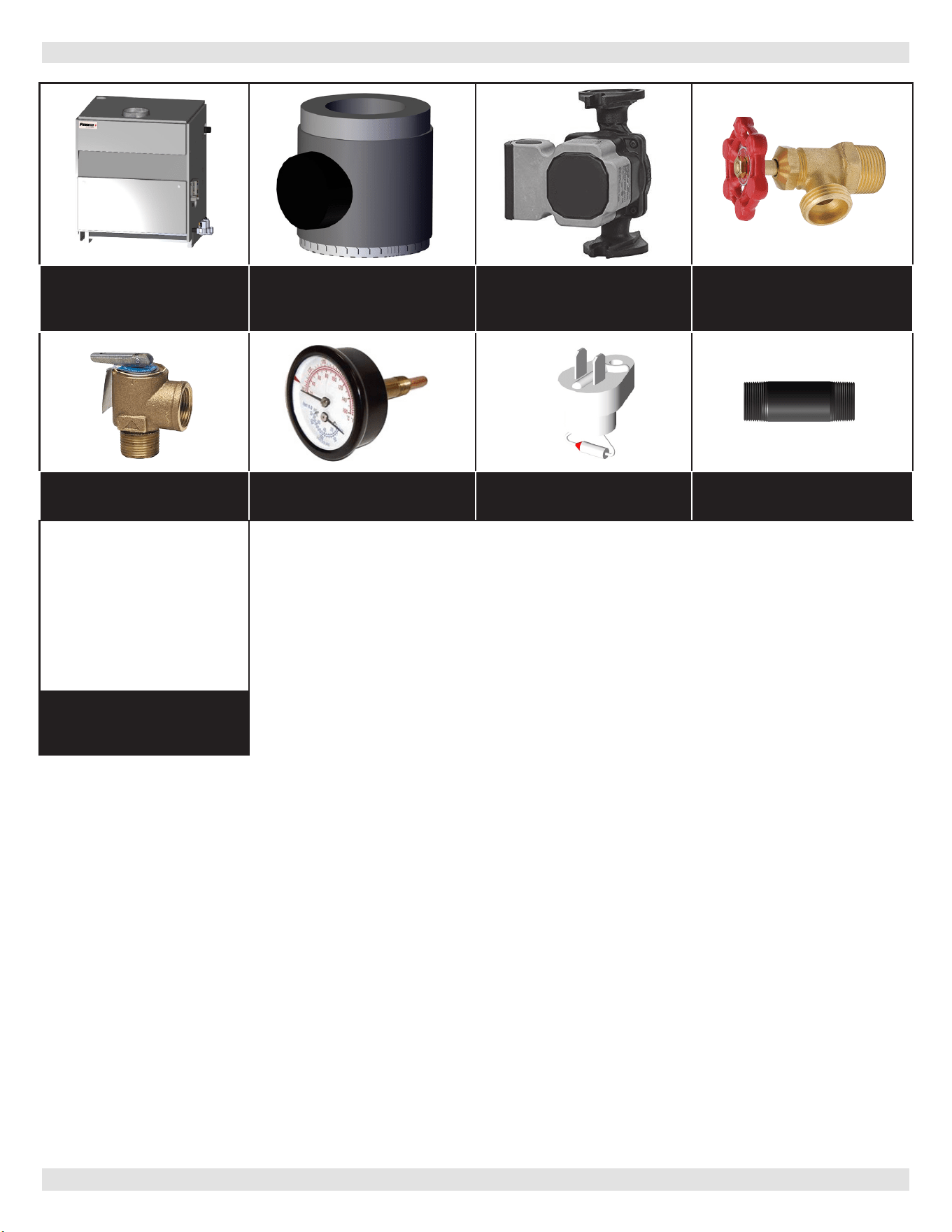
Fully Assembled Boiler Vent Damper Pump (Optional) *Drain Valve
*ASME Safety Relief
Valve
*Tridicator
*Fuse Link w/
Instruction Tag
*Nipple 3/4”x6-1/2 “
Includes Essential
Documents and Warranty
11x17 Wire Diagrams
Document Package *Circulator Harness
Information and specications outlined in this manual in eect at the
time of printing of this manual. ECR International reserves the right to
discontinue, change specications or system design at any time without
notice and without incurring any obligation, whatsoever.
* Items found in parts box included with your boiler.
KEEP THIS MANUAL NEAR BOILER
RETAIN FOR FUTURE REFERENCE
For Parts lists see manual 240013341 included with your boiler literature package.
ITEMS INCLUDED WITH YOUR BOILER
PN 240013340 Rev. C [12/02/2022]

3
Contents
1 - Dimensions ............................................................ 4
2 - Safety Symbols And Warnings .................................. 5
2 - Safety Symbols And Warnings .................................. 6
3 - Locating The Boiler ................................................. 7
4 - Connecting Supply And Return Piping ........................ 9
5 - Ventilation & Combustion Air .................................. 14
6 - Chimney And Vent Pipe Connection ......................... 15
7 - Vent Damper Operation ......................................... 17
8 - Gas Supply Piping ................................................. 18
9 - Electrical Wiring ................................................... 19
10 - Wiring Diagram .................................................. 20
11 - General Instructions ............................................ 21
12 - Lighting Instructions ........................................... 22
13 - Operating Your Boiler .......................................... 23
14 - Service Hints ...................................................... 26
15 - Maintaining Your Boiler ........................................ 27
16 - Boiler Ratings And Capacities ............................... 28
Appendix A - Control Function ..................................... 29
Appendix B - Vent Damper Installation ......................... 32
TABLE OF CONTENTS
PN 240013340 Rev. C [12/02/2022]
4
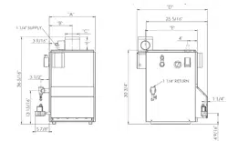
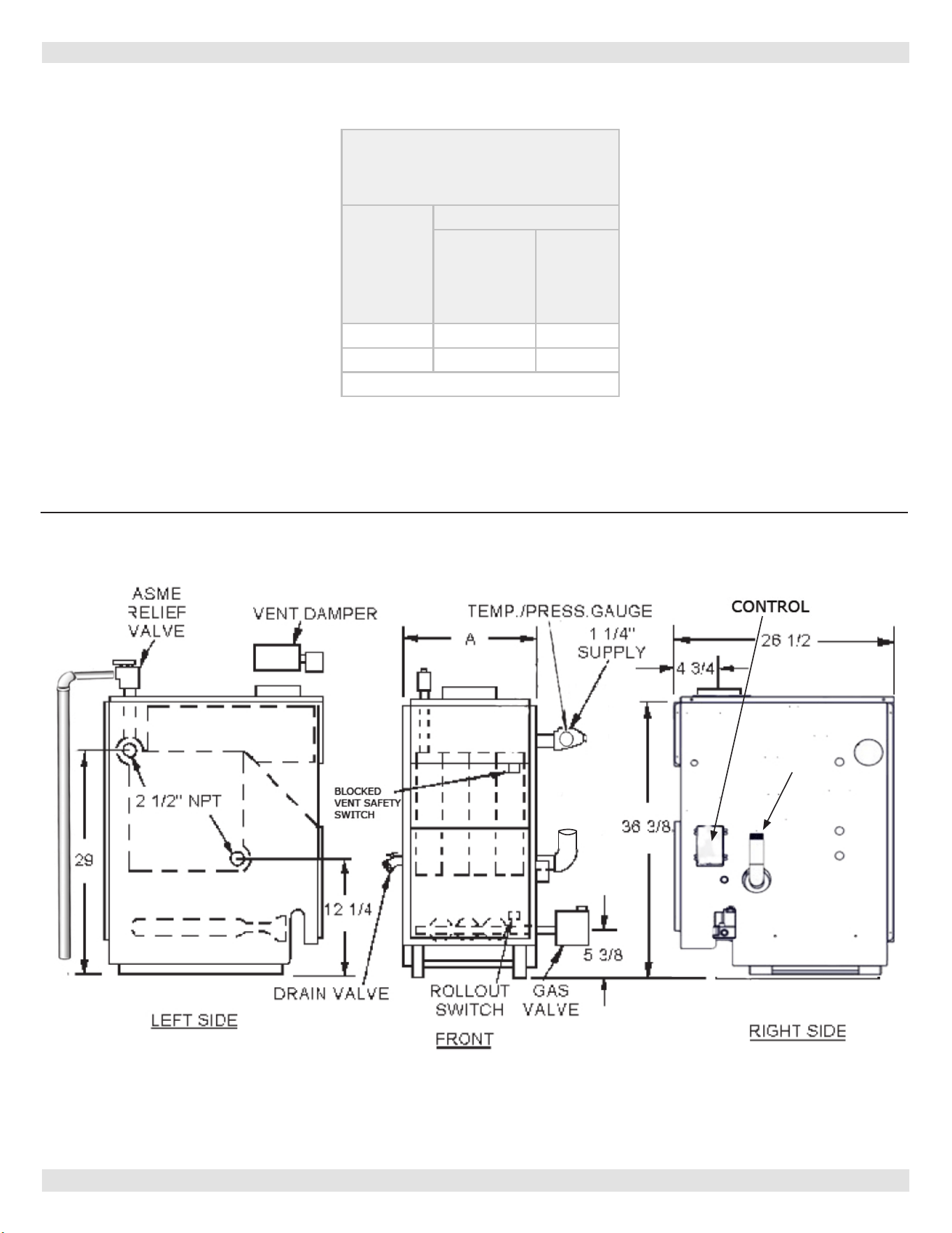
1 - DIMENSIONS
* Minimum acceptable height for Low Water Cuto probe.
Figure 1 - Dimensions
*
1 1/4” RETURN
PN 240013340 Rev. C [12/02/2022]
Table 1 - Dimensions
BOILER
MODEL
NUMBER
DIMENSIONS (INCH.)
FLUE
DIAMETER
“A”
WIDTH
15C-262 7 27½
15C-299 7 30¾
Add 5½” to height for vent Damper.
5
2 - SAFETY SYMBOLS AND WARNINGS
CAUTION
Indicates a hazardous situation which, if not
avoided, could result in minor or moderate injury.
!!
WARNING
Indicates a hazardous situation which, if not
avoided, could result in death or serious injury.
!
DANGER
Indicates a hazardous situation which, if not
avoided, WILL result in death or serious injury.
!
This is the safety alert symbol. Symbol alerts
you to potential personal injury hazards. Obey all
safety messages following this symbol to avoid
possible injury or death.
Become familiar with symbols identifying potential hazards.
Boiler installation shall be completed by qualied agency.
2.1. Safety Information
WARNING
Do not tamper with or use this boiler for any
purpose other than its intended use. Failure to
follow these instructions could result in death or
serious injury. Use only manufacturer recommended
parts and accessories.
!
CAUTION
Laceration, burn hazard. Metal edges and parts
may have sharp edges and/or may be hot. Use
appropriate personal protection equipment to
include safety glasses and gloves when installing
or servicing this boiler. Failure to follow these
instructions could result in minor or moderate injury.
!
NOTICE
Used to address practices not related to personal
injury.
WARNING
Fire, explosion, asphyxiation and electrical shock
hazard. Improper installation could result in death
or serious injury. Read this manual and understand
all requirements before beginning installation.
!
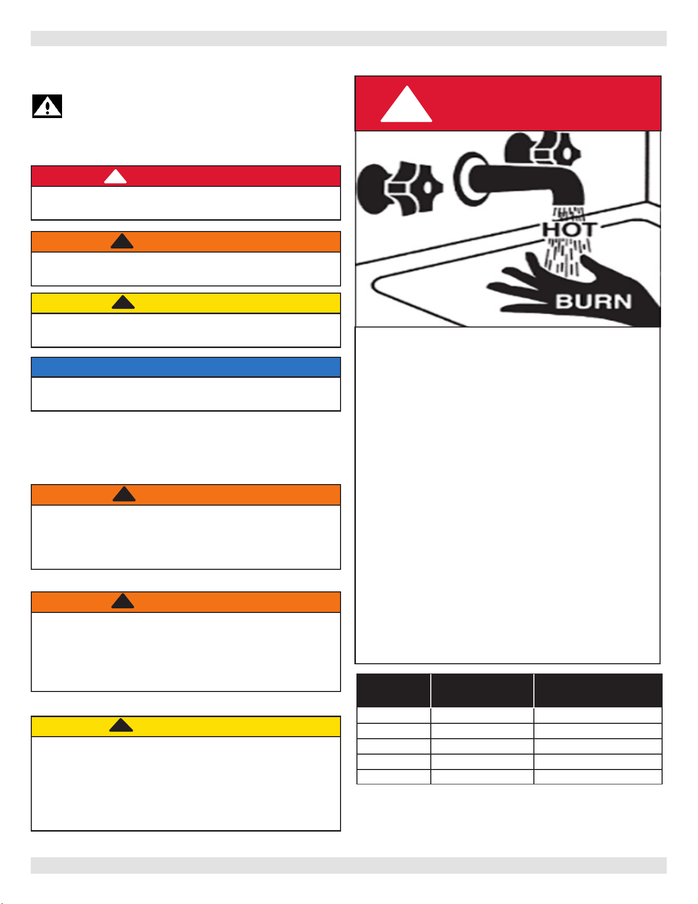
FOR YOUR SAFETY READ BEFORE OPERATING
Hot Water Can Scald!
Water heated to temperature for clothes washing,
dish washing and other sanitizing needs can scald and
cause permanent injury.
Children, elderly, and inrm or physically handicapped
persons are more likely to be permanently injured by
hot water. Never leave them unattended in bathtub or
shower. Never allow small children to use a hot water
tap or draw their own bath.
If anyone using hot water in the building ts the above
description, or if state laws or local codes require
certain water temperatures at hot water taps, you
must take special precautions:
• Use lowest possible temperature setting.
• Install some type of tempering device, such as
an automatic mixing valve, at hot water tap or
water heater. Automatic mixing valve must be
selected and installed according to manufacturer's
recommendations and instructions.
• Water passing out of drain valves may be
extremely hot. To avoid injury:
• Make sure all connections are tight.
• Direct water ow away from any person.
DANGER
!
Water
Temperature
Seng
1st Degree Burn
Exposure Time For
An Adult
2nd and 3rd Degree Burn
Exposure Time For An
Adult
120° F 1 minute 5 minutes
130° F 5 seconds 30 seconds
140° F 2 seconds 5 seconds
150° F 1 second 1.5 seconds
160° F Instantaneous 0.5 seconds
Note: Warning for Infants, Children, and Elderly:
Great care must be taken when exposing the
aforementioned groups to warm or hot water as they
can be badly burned in exposure times less than half
of the time for an adult.
PN 240013340 Rev. C [12/02/2022]
6
2 - SAFETY SYMBOLS AND WARNINGS
WARNING
Keep boiler area clear and free from combustible
materials, gasoline and other ammable vapors and
liquids.
DO NOT obstruct air openings to the boiler room.
Modication, substitution or elimination of factory
equipped, supplied or specied components may
result in personal injury or loss of life.
Installation and service of this boiler shall be performed
by a qualied installer.
When this product is installed in the Commonwealth
of Massachusetts the installation shall be performed
by a Licensed Plumber or Licensed Gas Fitter.
!
WARNING
This prod
uct contains Fibrous glass. Fibrous
glass is a synthetic ber made from tiny particles
of glass. Fibrous glass has been classied as a
possible human carcinogen. When disturbed as a
result of servicing or repair, brous glass becomes
airborne and, if inhaled, may be hazardous to
your health. It can harm the eyes, skin, and the
lungs. Airborne bers from these materials have
been listed by the State of California as a possible
cause of cancer through inhalation. Adhere
to the following precautions and procedures.
Avoid breathing dust and contact with skin and
eyes. Use NIOSH certied dust respirator (e.g.,
N95). Other types of respirators may be needed
depending on the job site conditions. Current NIOSH
recommendations can be found on the NIOSH
website https://www.cdc.gov/niosh/. Approved
respirators, manufacturers, and phone numbers
are also listed on this website. Wear appropriate
personal protective clothing to prevent skin contact,
as well as gloves and eye protection. Wash skin
daily at end of each work shift, and prior to eating,
drinking, smoking, etc. Workers whose clothing
may have been contaminated should change into
uncontaminated clothing before leaving the work
premises. Wash potentially contaminated clothes
separately from other clothing. Rinse clothes washer
thoroughly. Follow all Local, State and Federal
guidelines for disposal.
NIOSH stated First Aid. Eye: Irrigate immediately.
Breathing: Fresh air.
!
WARNING
Combustion chamber insulation in this product
contains ceramic ber material. Ceramic bers can
be converted to cristobalite in very high temperature
applications. The International Agency for Research
on Cancer (IARC) has concluded, Crystalline silica
inhaled in the form of quartz or cristobalite from
occupational sources is carcinogenic to humans
(Group1). Avoid breathing dust and contact
with skin and eyes. Use NIOSH certied dust
respirator (N95). This type of respirator is based
on the OSHA requirements for cristobalite at the
time this document was written. Other types of
respirators may be needed depending on the job
site conditions. Current NIOSH recommendations
can be found on the NIOSH website http://www.
cdc.gov/niosh/homepage.html. NIOSH approved
respirators, manufacturers, and phone numbers are
also listed on this website. Wear long-sleeved, loose
tting clothing, gloves, and eye protection. Apply
enough water to the combustion chamber lining to
prevent dust. Wash potentially contaminated clothes
separately from other clothing. Rinse clothes washer
thoroughly.
NIOSH stated First Aid. Eye: Irrigate immediately.
Breathing: Fresh air.
WARNING
Fire, Explosion, Asphyxiation, Electrical shock
hazard! Flooding will result in damages such as
electrical problems, corrosion, inoperative parts,
mold and other unforeseen issues which can
occur over time. Any equipment determined by
a professional as damaged by a ood, dened as
excess of water or other liquid, shall be replaced.
Failure to follow these directions will result in a
Hazardous Situation.
!
To Installer leave all instructions with boiler for future
reference.
WARNING
Keep boiler area clear and free from combustible
materials, gasoline and other ammable vapors and
liquids.
DO NOT obstruct air openings to the boiler room.
Modication, substitution or elimination of factory
equipped, supplied or specied components may
result in personal injury or loss of life.
Installation and service of this boiler shall be performed
by a qualied installer.
When this product is installed in the Commonwealth
of Massachusetts the installation shall be performed
by a Licensed Plumber or Licensed Gas Fitter.
!
WARNING
This prod
uct contains Fibrous glass. Fibrous
glass is a synthetic ber made from tiny particles
of glass. Fibrous glass has been classied as a
possible human carcinogen. When disturbed as a
result of servicing or repair, brous glass becomes
airborne and, if inhaled, may be hazardous to
your health. It can harm the eyes, skin, and the
lungs. Airborne bers from these materials have
been listed by the State of California as a possible
cause of cancer through inhalation. Adhere
to the following precautions and procedures.
Avoid breathing dust and contact with skin and
eyes. Use NIOSH certied dust respirator (e.g.,
N95). Other types of respirators may be needed
depending on the job site conditions. Current NIOSH
recommendations can be found on the NIOSH
website https://www.cdc.gov/niosh/. Approved
respirators, manufacturers, and phone numbers
are also listed on this website. Wear appropriate
personal protective clothing to prevent skin contact,
as well as gloves and eye protection. Wash skin
daily at end of each work shift, and prior to eating,
drinking, smoking, etc. Workers whose clothing
may have been contaminated should change into
uncontaminated clothing before leaving the work
premises. Wash potentially contaminated clothes
separately from other clothing. Rinse clothes washer
thoroughly. Follow all Local, State and Federal
guidelines for disposal.
NIOSH stated First Aid. Eye: Irrigate immediately.
Breathing: Fresh air.
!
WARNING
Combustion chamber insulation in this product
contains ceramic ber material. Ceramic bers can
be converted to cristobalite in very high temperature
applications. The International Agency for Research
on Cancer (IARC) has concluded, Crystalline silica
inhaled in the form of quartz or cristobalite from
occupational sources is carcinogenic to humans
(Group1). Avoid breathing dust and contact
with skin and eyes. Use NIOSH certied dust
respirator (N95). This type of respirator is based
on the OSHA requirements for cristobalite at the
time this document was written. Other types of
respirators may be needed depending on the job
site conditions. Current NIOSH recommendations
can be found on the NIOSH website http://www.
cdc.gov/niosh/homepage.html. NIOSH approved
respirators, manufacturers, and phone numbers are
also listed on this website. Wear long-sleeved, loose
tting clothing, gloves, and eye protection. Apply
enough water to the combustion chamber lining to
prevent dust. Wash potentially contaminated clothes
separately from other clothing. Rinse clothes washer
thoroughly.
NIOSH stated First Aid. Eye: Irrigate immediately.
Breathing: Fresh air.
WARNING
Fire, Explosion, Asphyxiation, Electrical shock
hazard! Flooding will result in damages such as
electrical problems, corrosion, inoperative parts,
mold and other unforeseen issues which can
occur over time. Any equipment determined by
a professional as damaged by a ood, dened as
excess of water or other liquid, shall be replaced.
Failure to follow these directions will result in a
Hazardous Situation.
!
To Installer leave all instructions with boiler for future
reference.
PN 240013340 Rev. C [12/02/2022]
7
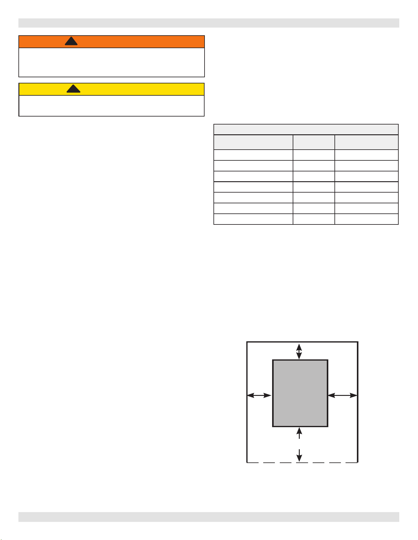
3 -LOCATING THE BOILER
Table 2 -
MINIMUM CLEARANCE DIMENSIONS
Inches (mm)
Top 6”
(152mm)
Rear 6”
(152mm)
Control Side 7” (178mm)
Opposite Side 6” (152mm)
Front
18” (457mm)
Flue/Vent Connector 6” (152mm)
Near Boiler Piping 2” (51mm)
NOTE: Greater clearances for access should supersede fire
protection clearances.
* Denition of Alcove is three sided space with no wall in
front of boiler. ANSI standard for alcove is 18 inches from
front of appliance to leading edge of side walls as shown
below.
Minimum Clearances to Combustible
Construction (as seen from above)
6"
BOILER
18"
6"
Front
7"
Control
Side
3.1 Installation Requirements
CAUTION
Boiler weight exceeds 200 pounds (90.7 kg). Do not
lift boiler without assistance.
!!
WARNING
Fire hazard. Do not install boiler on combustible
ooring or carpeting. Failure to follow these
instructions could result in death or serious injury.
!
1.
Installation shall conform to the requirements
of the authority having jurisdiction or, in the
absence of such requirements, to the National
Fuel Gas Code, ANSI Z223.1/NFPA 54, and/or
Natural Gas and Propane Installation Code, CAN/
CSA B149.1.
2.
Where required by the authority having
jurisdiction, the installation shall conform to the
Standard for Controls and Safety Devices for
Automatically red Boilers, ANSI/ASME CSD-1.
3.
The Installer shall verify that at least one carbon
monoxide alarm has been installed within a
residential living space or home following the
alarm manufactuer’s instructions and applicable
local codes before putting the appliance into
operation.
4.
Boiler series is classied as a Category I. Vent
installation shall be in accordance with “Venting of
Equipment”, of the National Fuel Gas Code, ANSI
Z223.1/NFPA 54, or “Venting Systems and Air Supply
for Appliances,” of the Natural Gas and Propane
Installation Code, CAN/CSA B149.1, or applicable
provisions of the local building codes.
5.
Boiler has met safe lighting and other performance
criteria with the gas manifold and control assembly on
the boiler per the latest revision of ANSI Z21.13/CGA
4.9.
6.
Install boiler such that gas ignition system components
are protected from water (dripping, spraying, rain,
etc.) during appliance operation and service, (circulator
replacement, condensate trap, control replacement,
etc.).
7.
Locate boiler on level, solid base as near chimney as
possible and centrally located with respect to heat
distribution system as practical.
8.
Allow 24 inches (610mm) at front and right side for
servicing and cleaning.
9.
When installed in utility room, door should be wide
enough to allow largest boiler part to enter, or to
permit replacement of another appliance such as water
heater.
10.
FOR INSTALLATION ON NON-COMBUSTIBLE
FLOORS ONLY - For installation on combustible
ooring special base shall be used. Please refer to
(Combustible Floor Addendum) included in literature
envelope provided with boiler and outlined in National
Fuel Gas Code, ANSI Z223.1/NFPA 54. Do Not Install
Boiler on carpeting.
PN 240013340 Rev. C [12/02/2022]
8
3.3 Boiler Location Considerations
• Ambient room temperature always above 32°F (0°C) to
prevent the potential of freezing.
• Drainage of water (or water/ antifreeze solution) during
boiler service or from safety relief valve discharge.
• Access to system water piping, gas supply, and
electrical service.
• Boiler shall be installed on at level surface which is
capable of supporting the weight of the boiler, water,
and equipment.
• Raise boiler above the oor on blocks if oor may get
wet.
3 - LOCATING THE BOILER
Items to Avoid
Products Which May Contain These
Items
Areas Where These Items May Be
Found
Chlorine, Fluorine, and Compounds
Spray cans containing chlorouorocarbons
Chlorinated waxes/cleaners
Chlorine-based swimming pool chemicals
Calcium chloride used for thawing
Sodium chloride used for water softening
Swimming pool or spa chemicals
De-icing salts or chemicals
Carbon Tetrachloride
Swimming pools and pool storage areas
Laundry room (Note 2)
Conned storage areas
Airborne Particulates
Drywall dust
Road or gravel dust
Dryer lint
Cat litter
Construction or remodelling areas (Note 1)
Laundry room (Note 2)
Acids, Solvents, etc.
Paint, Varnish, Turpentine, etc.
Cleaning Solvents
Hydrochloric acid/muriatic acid
Cements, adhesives and glues
Photo processing plants
Garages with workshops
Furniture renishing areas and
establishments
Laundry Chemicals
Laundry detergents, bleaches, fabric
softeners, etc.
Antistatic fabric softeners (dryer sheets)
Dry cleaning/laundry areas and
establishments
Other
Permanent wave solutions
Refrigerants (Freon, etc) (only where
the refrigerant may be leaking from the
appliance)
Beauty shops
Refrigeration repair shops
Notes:
1. It is recommended the boiler be isolated and not operated during construction/
renovation. Excessive particles ingested by the boiler may accumulate in the ueway
passages possibly resulting in unsafe operation. In this case, unit servicing shall include
cleaning of ueway passages and burner ports.
2. If locating boiler in laundry room is unavoidable, it is manufacturer recommended
the room be generously ventilated (well in excess of combustible air requirements), and
homeowner seal laundry supply containers, and minimize room vapors.
3. Piping allowing fresh air in should also be considered. See Section 5-1.
Table 3-1: CONTAMINANTS
• Horizontal run to chimney shall be as short as possible.
• System piping exposed to freezing conditions: Use
inhibited propylene glycol solutions certied by uid
manufacturer for use with closed water heating system.
Do not use automotive or ethylene glycol.
PN 240013340 Rev. C [12/02/2022]
9
4 - CONNECTING SUPPLY AND RETURN PIPING
RELIEF VALVE
DISCHARGE
LINE
Check local
codes for
maximum
distance
from oor
or allowable
safe point of
discharge.
Figure 2 - Safety Relief Valve
1.
Refer to local codes and appropriate ASME Boiler
and Pressure Vessel Code for additional installation
requirements. Install safety relief valve using pipe
ttings provided with boiler. See Figure 2.
2.
Install safety relief valve with spindle in vertical
position.
3.
Do not install shuto valve between boiler and safety
relief valve.
4.
Install discharge piping from safety relief valve. See
Figure 2.
• Use ¾” or larger pipe.
• Use pipe suitable for temperatures of 375°F (191°C)
or greater.
• Individual boiler discharge piping shall be independent
of other discharge piping.
• Size and arrange discharge piping to avoid reducing
safety relief valve relieving capacity below minimum
relief valve capacity stated on rating plate.
• Run pipe as short and straight as possible to location
protecting user from scalding and properly drain
piping.
• Install union, if used, close to safety relief valve outlet.
• Install elbow(s), if used, close to safety relief valve
outlet and downstream of union (if used).
• Terminate pipe with plain end (not threaded).
• Terminate freely to atmosphere where discharge is
clearly visible and no risk of freezing.
WARNING
Burn and scald hazard. Safety relief valve could
discharge steam or hot water during operation.
Install discharge piping per these instructions.
!
WARNING
Burn and scald hazard. Safety relief valve shall be
installed with spindle in upright position only,
following ASME BPV code. Failure to follow these
instructions could result in death or serious injury.
!
PN 240013340 Rev. C [12/02/2022]
10
4.3 Flush and Rinse System
Flush the entire system and rinse thoroughly to ensure no
sludge will be introduced into the heating body of the boiler.
NOTICE
If damage due to frozen pipes is a possibility, install
appropriate safeguards and alarms on the heating
system to prevent property damage due to frozen
and burst pipes should the boiler heating system
become inoperative due to a power outage, safety
lockout or component failure.
4.4 Water Treatment
Manufacturer recommends a water analysis be done on
water used to ll the system. Treatment may be required
based on the analysis results. For extremely hard water or
pH below 7.0 consult your local water treatment company.
Manufacturer recommends a water analysis be done on
water used to ll the system. Treatment may be required
based on the analysis results.
For extremely hard water or pH below 7.0 consult your
local water treatment company.
• If CH water is very hard or full of impurities, it must be
adequately ltered and treated, otherwise damage and/
or malfunction could be caused. Recommended water
quality is
:
o Hardness Less than 150 mg/L
o Acidity level 7-8 pH
o Sediments Particle size less than 50 micron
• If the water quality is outside these ranges, consult a local
water treatment specialist for recommendations.
• If the water is treated, do not use petroleum based
products or products containing mineral oil or hydrocarbons
in order to avoid likely damage to parts made from rubber
compounds (o-rings).
4 - CONNECTING SUPPLY AND RETURN PIPING
WARNING
• Poison hazard. Ethylene glycol is toxic. Do not
use ethylene glycol.
• Never use automotive or standard glycol
antifreeze, even ethylene glycol made for hydronic
systems.
• Ethylene glycol can attack gaskets and seals used
in hydronic systems.
• Do not use petroleum based cleaning or sealing
compounds boiler system.
• Do not ll boiler or boiler system with softened
water.
• Use only inhibited propylene glycol solutions
certied by uid manufacturer as acceptable for
use with closed water heating system.
• Thoroughly clean and ush any system that used
glycol before installing new Boiler.
• Provide user with Material Safety Data Sheet
(MSDS) on uid used.
!
PN 240013340 Rev. C [12/02/2022]
11
4 - CONNECTING SUPPLY AND RETURN PIPING
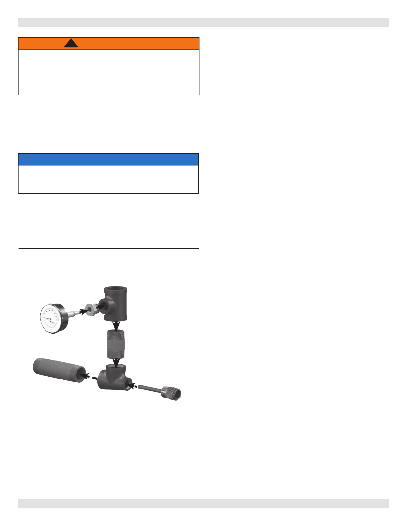
Figure 3 - Temperature Pressure Gauge
Install sand strainer when water supply is from a well or
pump.
Install hot water boiler above radiation level or as required
by Authority having jurisdiction.
Periodic inspection is necessary, as is ushing of oat type
devices, per manufacturers specic instruction.
Boiler is factory equipped with low water cuto.
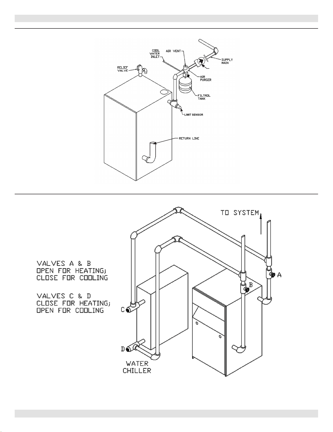
FOR USE WITH COOLING UNITS
A. Boiler used in connection with refrigeration system, must
be installed so that chilled medium is piped in parallel
with heating boiler. Appropriate valves must be used to
prevent chilled medium from entering heating boiler. See
Figure 5 page 12.
B. Boiler connected to heating coils located in air handling
units where they may be exposed to refrigerated air
circulation, piping system shall be equipped with ow
control valves or other automatic means to prevent
gravity circulation of boiler water during cooling cycle.
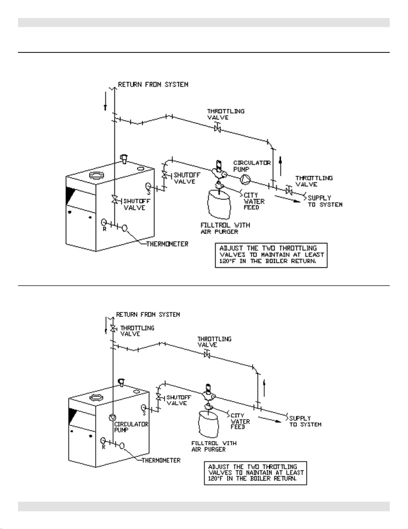
LOW WATER TEMPERATURE AND LARGE WATER
CONTENT SYSTEM (See Figures 6 and 7, Page 13.)
Signicant condensation may form in boiler and/or venting
system if boiler is operated for long period of time with
return temperatures of less than 120° F.
Condensate is corrosive and can cause severe damage to
boiler and venting system. Minimum design return water
temperature to prevent condensation in boiler and venting
is 120°F. Minimum high limit setting is 140°F.
1.
Boiler used in heating system where design water
temperatures below 140°F are desired (e.g. radiant
oor heating), 4-way mixing valve or suitable
alternative is required to prevent low temperature
return water from entering boiler. Follow mixing valve
manufacturer’s instructions.
2.
Boiler connected to system having large water content
(such as former gravity system), install system bypass.
See Figures 6 and 7, page 13.
3.
If boiler water reset control is used to operate boiler,
minimum reset supply water temperature setpoint
must be at least 140°F, unless mixing valve is used as
in (1) above.
1.
Boiler is shipped assembled. Install discharge piping
from safety relief valve. See Warning, Page 9.
2.
Install temperature pressure gauge.
• Apply pipe sealant to threads on shaft of gauge.
• Thread gauge into supply water tee. See Figure 3.
NOTICE
Do not tighten gauge by hand. Gauge should be
tightened using crescent wrench or 9/16” open end
wrench. See Figure 3.
3.
Install sensor all the way so it is touching the back of
the well for proper operation.
4.
Connect supply and return lines to boiler. Connections
may require additional ttings and parts, as shown on
diagrams.
Verify clean water supply is available to water inlet valve.
WARNING
Burn and scald hazard. Safety relief valve could
discharge steam or hot water during operation.
Install discharge piping per these instructions. Failure
to follow these instructions could result in death or
serious injury.
!
PN 240013340 Rev. C [12/02/2022]
12
Figure 5 - Chilled Water Piping
Figure 4 - Typical Hot Water Piping
4 - CONNECTING SUPPLY AND RETURN PIPING
CIRCULATOR
PUMP
PN 240013340 Rev. C [12/02/2022]
13
Figure 6 - BYPASS PIPING - CIRCULATOR ON SUPPLY
Figure 7 - BYPASS PIPING - CIRCULATOR ON RETURN
Bypass Piping Required For High Mass (Large Water Content) Systems
4 - CONNECTING SUPPLY AND RETURN PIPING
PN 240013340 Rev. C [12/02/2022]

14
5 - VENTILATION & COMBUSTION AIR
Provide combustion air and ventilation air in accordance
with the section “Air for Combustion and Ventilation,” of the
National Fuel Gas Code, ANSI Z223.1/NFPA 54, or Natural
Gas and Propane Installation Code, CAN/CSA B149.1, or
applicable provisions of local building codes.
Provide make-up air where exhaust fans, clothes dryers,
and kitchen ventilation equipment interfere with proper
operation.
National Fuel Gas Code recognizes several methods
of obtaining adequate ventilation and combustion air.
Requirements of the authority having jurisdiction may
override these methods.
• Engineered Installations. Must be approved by
authority having jurisdiction.
• Mechanical Air Supply. Provide minimum of 0.35
cfm per Mbh for all appliances located within space.
Additional requirements where exhaust fans installed.
Interlock each appliance to mechanical air supply
system to prevent main burner operation when
mechanical air supply system not operating.
• All Indoor Air. Calculate minimum allowable room
volume for all appliances in space. Use a dierent
method if minimum volume not available.
A. Standard Method. Cannot be used if known air
inltration rate is less than 0.40 air changes per
hour. See Table 4 for space with boiler only. Use
equation for multiple appliances.
Volume ≥ 50 ft
3
x Total Input [Mbh]
B. Known Air Inltration Rate. See Table 4 for
space with boiler only. Use equation for multiple
appliances. Do not use an air inltration rate
(ACH) greater than 0.60.
Volume ≥
21 ft
3
⁄ACH x Total Input [Mbh]
C. Refer to National Fuel Gas Code for opening
requirements between connected indoor spaces.
• All Outdoor Air. Provide permanent opening(s)
communicating directly or by ducts with outdoors.
A. Two Permanent Opening Method. Provide opening
commencing within 12 inches of top and second
opening commencing within 12 inches of bottom of
enclosure.
Direct communication with outdoors or
communicating through vertical ducts. Provide
minimum free area of 1 in² per 4 Mbh of total
input rating of all appliances in enclosure.
Communicating through horizontal ducts.
Provide minimum free area of 1 in² per 2
Mbh of total input rating of all appliances in
enclosure.
B. One Permanent Opening Method. Provide opening
commencing within 12 inches of top of enclosure.
Provide minimum clearance of 1 inch on sides/back
and 6 inches on front of boiler (does not supersede
clearance to combustible materials).
• Refer to National Fuel Gas Code for additional
requirements for louvers, grilles, screens and air
ducts.
• Combination Indoor and Outdoor Air. Refer to National
Fuel Gas Code for application information.
PN 240013340 Rev. C [12/02/2022]

15
Boilers connecting to gas vents or chimneys, vent
installations shall be in accordance with “Venting of
Equipment”, of the National Fuel Gas Code, ANSI
Z223.1/NFPA 54 or “Venting Systems and Air Supply for
Appliances,” of the Natural Gas and Propane Installation
Code, CAN/CSA B149.1, or applicable provisions of the
local building codes.
Check Your Chimney
It must be clean, right size, properly constructed and in
good condition.
Chimney Sizing
Chimney sizing, and vent installation must be in accordance
with The National Fuel Gas Code, ANSI Z223.1/NFPA 54 or
CAN/CSA B149.1, or applicable provisions of local building
codes.
This is a high eciency boiler with low stack temperature.
Following recommendations are in addition to requirements
of the National Fuel Gas Code.
1. Type B double wall vent pipe is recommended for vent
connector. Single wall vent connectors should not be
used unless following conditions are true:
a) Except for basement, boiler is not installed in
unheated space.
b) Total horizontal portion of vent connector, not
including elbows is less than 5 feet in length.
2. Outside chimneys (i.e. chimneys exposed to outdoors
below roof line) should not be used unless they are:
a) enclosed in a chase, or
b) lined with type B vent pipe, or listed exible vent
liner, or other certied chimney lining system.
3. Where possible it is recommended to common vent
boiler and water heater.
4. For multiple boiler installations, consult boiler
manufacturer for venting recommendations.
6 - CHIMNEY AND VENT PIPE CONNECTION
WARNING
Boiler and venting installations shall be performed
by a qualied expert and in accordance with the
appropriate manual. Installing or venting boiler
or other gas appliance with improper methods or
materials may result in serious injury or death due
to re or to asphyxiation from poisonous gases
such as carbon monoxide with is odorless and
invisible.
!
1.
Vent pipe must slope upward from the boiler not less
than ¼ inch for every 1 foot (21 mm/m) to verticle
vent terminal.
2.
Horizontal portions of venting system shall be
supported rigidly every 5 feet and at the elbows. No
portion of vent pipe should have any dips or sags.
Requirements
3.
Boiler series is classied as a Category I. Vent
installation shall be in accordance with “Venting of
Equipment,” of the National Fuel Gas Code, ANSI
Z223.1/NFPA 54, or “Venting Systems and Air Supply
for Appliances,” of the Natural Fuel Gas and Propane
Installation Code, CAN/CSA B149.1, or applicable
provisions of the local building codes.
4.
Inspect chimney. Chimney shall be constructed and
lined according to NFPA 211 and NFPA 54/ANSI Z223.1.
Vent connector shall be Type B, or metal pipe having
resistance to heat and corrosion not less than that of
galvanized sheet steel or aluminum not less than 26
gauge thick, 24 gauge for 6 and 7 inch.
5.
Connect ue pipe from draft hood to chimney. Bolt or
screw joints together to avoid sags. Flue pipe should
not extend beyond inside wall of chimney more than
1/4 inch. Do not install manual damper in ue pipe
or reduce size of ue outlet except as provided by
the latest revision of National Fuel Gas Code, ANSI
ANSI Z223.1/NFPA 54 or CAN/CSA B149.1. Protect
combustible ceiling and walls near ue pipe as
required by National Fuel Gas Code. Where two or
more appliances vent into a common ue, the area of
the common ue must be at least equal to the area
of the largest ue plus 50 percent of the area of each
additional ue.
Chimney Inspection
Chimney must be clean, right size, properly constructed
and in good condition.
Installation must conform to requirements of the authority
having jurisdiction or, in absence of such requirements, to
The National Fuel Gas Code, ANSI Z223.1/NFPA 54.
Vent Pipe
• Fasten sections of vent pipe with 3 sheet metal screws
at each joint to make piping rigid.
• Support horizontal portions of vent system to prevent
sagging.
• Use stove pipe wires or metal strapping every 5’ to
support pipe from above.
• Vent pipe through crawl space, use double wall vent
pipe.
• Vent pipe passing through combustible wall or partition,
use ventilated metal thimble. Thimble should be 4"
larger in diameter than vent pipe.
NOTICE
Minimum Vent Pipe Clearance - Wood and other
combustible materials must not be closer than 6”
from any surface of single wall metal vent pipe.
Listed Type B vent pipe or other listed venting
systems shall be installed in accordance with their
listing.
PN 240013340 Rev. C [12/02/2022]

16
6 - CHIMNEY AND VENT PIPE CONNECTION
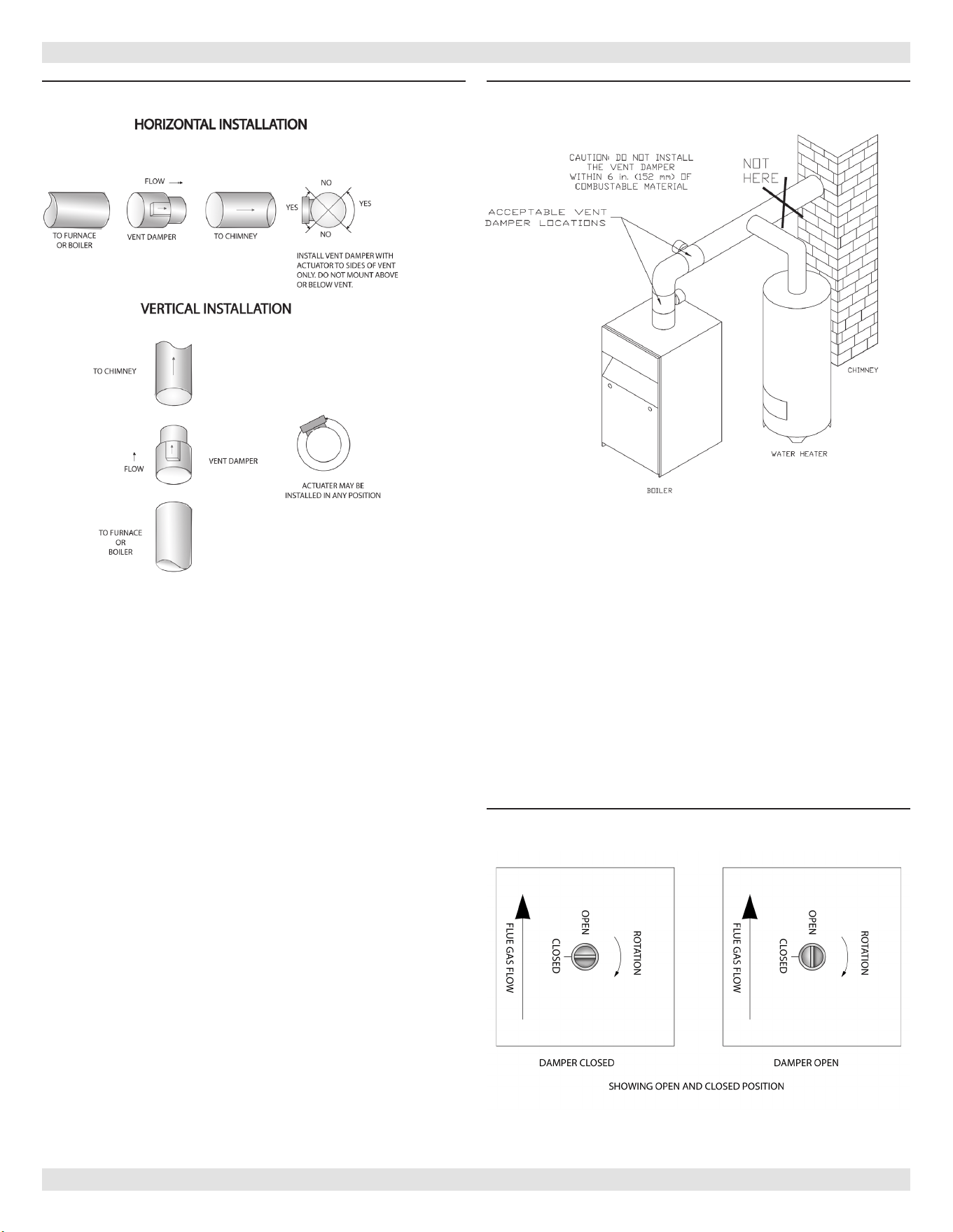
Connecting The Vent Damper And Vent Connector
Refer to Figure 1, page 4 for size and location of vent (ue
opening).
NOTICE
Damper blade on furnished vent damper has 1/2
square inch hole (approximately 3/4” diameter).
Boilers equipped with intermittent ignition, hole
should be plugged by using plug supplied with vent
damper.
1.
Position furnished vent damper on top of ue outlet
collar. Fasten damper securely to ue outlet collar with
sheet metal screws. Verify damper blade has clearance
to operate inside of diverter. Do not modify either draft
diverter or vent damper during installation.
As An Option
Damper may be installed in horizontal or vertical
position, closer to ue outlet collar preferred. See
Figures 8, 9 and 10 and enclosed vent damper
instructions.
2.
Install vent damper to service only single boiler for
which it is intended. Damper position indicator shall be
in visible location following installation. Locate damper
so it is accessible for servicing. See Figure 9.
3.
Damper must be in the open position when appliance
main burners are operating.
4.
Boiler is equipped with factory wired harness that plugs
into vent damper.
5.
Slope pipe up from boiler to chimney not less than 1/4”
per foot.
6.
Run pipe as directly as possible with as few elbows as
possible.
7.
Do not connect to replace ue.
8.
End of vent pipe must be ush with inside face of
chimney ue. Use a sealed-in thimble for chimney
connection.
Fasten sections of vent pipe with sheet metal screws to
make piping rigid. Support horizontal potions of vent
system to prevent sagging. Use stovepipe wires every 5’ to
support pipe from above. Use double wall vent pipe if vent
pipe must go through crawl space. Where vent pipe passes
through combustible wall or partition, use ventilated metal
thimble. Thimble should be 4 inches larger in diameter than
vent pipe.
Removing Existing Boiler From Common Venting
System
When an existing boiler is removed from common venting
system, common venting system is likely to be too large for
proper venting of appliances remaining connected to it.
At time of removal of existing boiler, following steps shall
be followed with each appliance remaining connected to the
common venting system placed in operation, while other
appliances remaining connected to common venting system
are not in operation.
1.
Seal any unused openings in the common venting
system.
2.
Visually inspect the venting system for proper size and
horizontal pitch and determine there is no blockage or
restriction, leakage, corrosion and other deciencies
which could cause an unsafe condition.
3.
Insofar as is practical, close all building doors and
windows and all doors between the space in which the
appliances remaining connected to the common venting
system are located and other spaces of the building.
Turn on clothes dryers and any appliance not connected
to the common venting system. Turn on any exhaust
fans, such as range hoods and bathroom exhausts, so
they will operate at maximum speed. Do not operate a
summer exhaust fan. Close replace dampers.
4.
Place in operation the appliance being inspected. Follow
the lighting instructions. Adjust thermostat so appliance
will operate continuously.
5.
Test for spillage at the draft hood relief opening after
5 minutes of main burner operation. Use the ame of
a match or candle, or smoke from a cigarette, cigar or
pipe.
6.
After it has been determined that each appliance
remaining connected to the common venting system
properly vents when tested as outlined above, return
doors, windows, exhaust fans, replace dampers and
any other gas-burning appliance to their previous
conditions of use.
7.
Any improper operation of the common venting system
should be corrected so the installation conforms with
the National Fuel gas Code, ANSI Z223.1/NFPA 54,
and/or the Natural Gas and Propane Installation Code,
CAN/CSA B149.1. When re-sizing any portion of the
common venting system, the common venting system
should be re-sized to approach the minimum size
determined using the appropriate tables in Chapter 13
of the National Fuel Gas Code, ANSI Z223.1/NFPA 54,
and/or the Natural Gas and Propane Installation Code,
CAN/CSA B149.1.
WARNING
Do not connect boiler to any portion of mechanical
draft system operating under positive pressure.
!
PN 240013340 Rev. C [12/02/2022]
17
7 - VENT DAMPER OPERATION
Figure 8 - Vent Damper Installation Figure 9 - Vent Damper Placement
Annually check vent damper and all ue product carrying
areas of appliance, with particular attention given to
deterioration from corrosion or other sources. If you see
corrosion or other deterioration, contact your heating
contractor for repairs. Check vent damper operation as
follows:
• When boiler is o, check vent damper positions
indicator points to closed position, Figure 10.
• Turn thermostat or controller up to call for heat and
check vent damper indicator points to open position.
• Turn thermostat or controller down again and check
damper position indicator returns to closed position.
Vent Damper Manual Operation
Vent damper may be placed in open position to permit
burner operation by using “HOLD DAMPER OPEN” switch,
located on damper controller. Thermostat will control
burner ring as before, while damper will remain open.
DO NOT turn damper open manually or motor damage will
result. Set switch to “AUTOMATIC OPERATION” to close
vent damper during burner o cycle.
For further information, and vent damper troubleshooting
guide, refer to manual packaged with vent damper and
Appendix B of this manual.
Inspect vent damper at least once a year by a
qualied service technician.
Figure 10 - Vent Damper Position Indicator
PN 240013340 Rev. C [12/02/2022]
18
8 - GAS SUPPLY PIPING
CAUTION
WHAT TO DO IF YOU SMELL GAS
• Do not try to light any appliance.
• Do not touch any electrical switch; do not use
any phone in your building.
• Immediately call your gas supplier from a
neighbor’s phone. Follow gas supplier’s
instructions.
• If you cannot reach your gas supplier, call the re
department.
!!
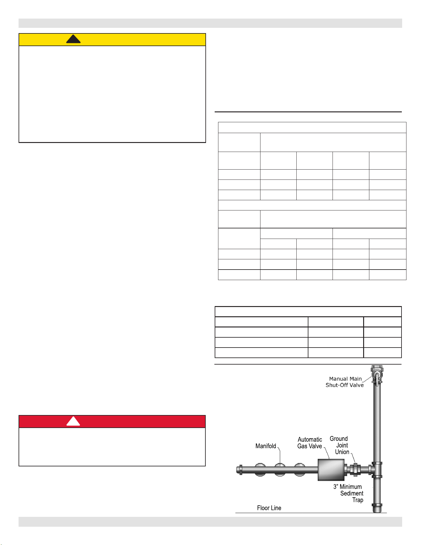
CHECK GAS SUPPLY
Gas pipe to your boiler must be correct size for length of
run and for total BTU per hour input of all gas utilization
equipment connected to it. See Table 5 for proper size.
Be sure your gas line complies with local codes and gas
company requirements.
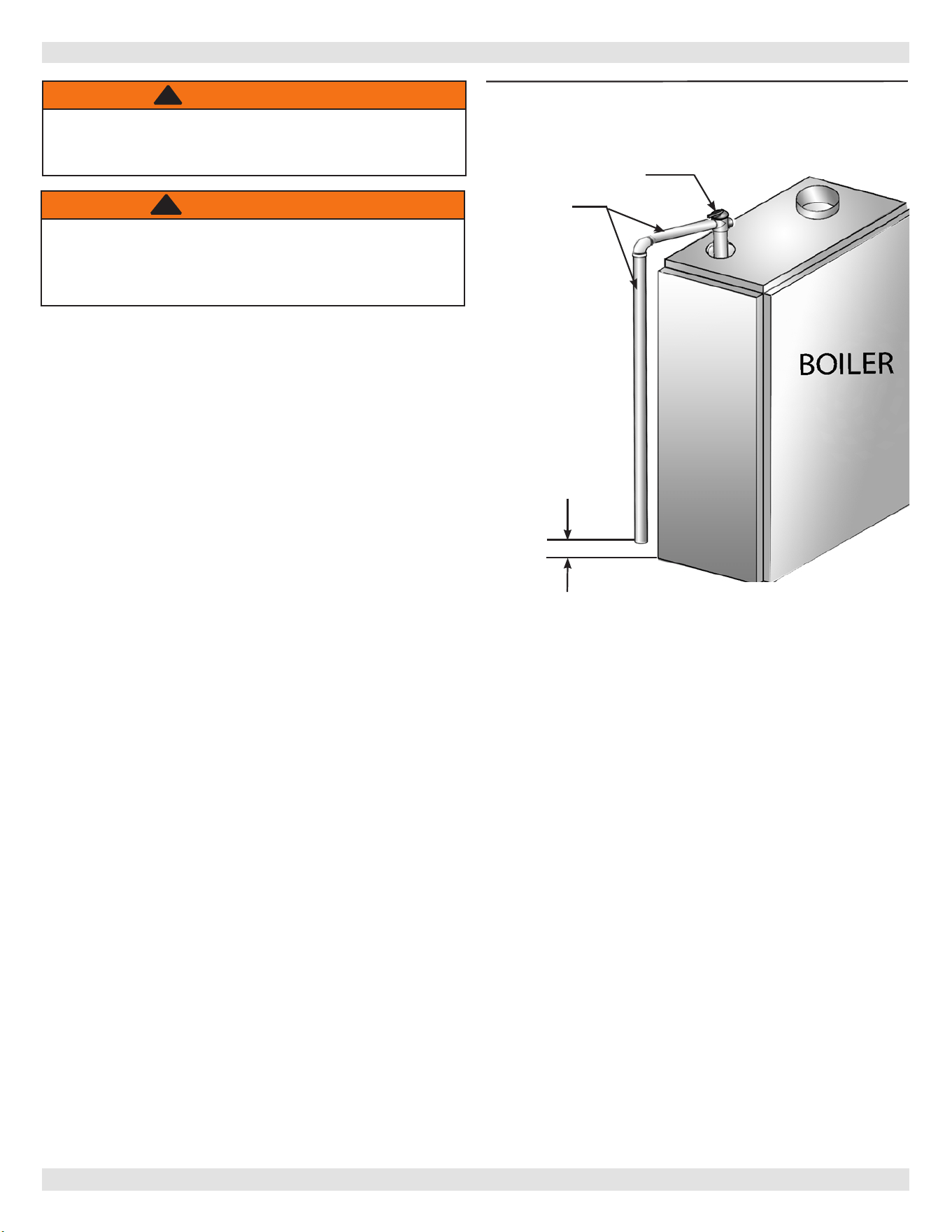
CONNECTING THE GAS PIPING See Figure 11.
Gas line enters boiler from right side.
• Use piping materials and joining methods acceptable
to authority having jurisdiction. In absence of such
requirements:
• USA - National Fuel gas Code, ANSI Z223.1/NFPA 54
• Canada - Natural Gas and Propane Installation Code,
CAN/CSA B149.1
• Use pipe joint compound suitable for LP gas on male
threads only.
• Use ground joint unions.
• Install sediment trap upstream of gas controls.
• Use two pipe wrenches when making connection to gas
valve to keep it from turning.
• Install manual shut-o valve in vertical pipe about 5
feet above oor.
• Tighten all joints securely.
• Propane gas connections should only be made by
licensed propane installer.
• Two-stage regulation should be used by propane
installer.
• Propane gas piping should be checked out by propane
installer.
CHECKING GAS PIPING
Pressure test boiler and gas connection before placing
boiler in operation
.
• Pressure test over 1/2 psig (3.5 kPa). Disconnect
boiler and its individual gas shuto valve from gas
supply system.
NATURAL GAS
Pipe Capacity - BTU Per Hour Input
Includes Fittings
Length of
Pipe - FT
½” ¾” 1” 1¼”
20 92,000 190,000 350,000 625,000
40 63,000 130,000 245,000 445,000
60 50,000 105,000 195,000 365,000
PROPANE GAS
Pipe Capacity - BTU Per Hour Input
Includes Fittings
Length of
Pipe - FT
Copper Tubing * Iron Pipe
⅝” ¾” ½” ¾”
20 131,000 216,000 189,000 393,000
40 90,000 145,000 129,000 267,000
60 72,000 121,000 103,000 217,000
* Outside diameter
Measure length of pipe or tubing from gas meter or
propane second stage regulator.
Table 5 - Gas Pipe Sizes
3” Minimum
Sediment
Trap
Manifold
Floor Line
Automatic
Gas Valve
Ground
Joint
Union
Figure 11 - Gas Piping
GAS PRESSURE
NATURAL GAS PROPANE
MIN. SUPPLY PRESSURE 5" w. c. 11" w. c.
MAX. SUPPLY PRESSURE 13.5" w. c. 13.5" w. c.
MANIFOLD PRESSURE 3.5" w. c. 11" w. c.
DANGER
Fire Hazard. Do not use matches, candles, open
ames, or other methods providing ignition source.
Failure to comply will result in death or serious
injury.
!
• Pressure test at 1/2 psig (3.5 kPa) or less. Isolate
boiler from gas supply system by closing manual gas
shuto valve.
• Locate leakage using gas detector, noncorrosive
detection uid, or other leak detection method
acceptable to authority having jurisdiction. Do not
use matches, candles, open ames, or other methods
providing ignition source.
• Correct leaks immediately and retest.
PN 240013340 Rev. C [12/02/2022]
19
9 - ELECTRICAL WIRING
Electrically bond boiler to ground in accordance with
requirements of authority having jurisdiction. Refer to:
• USA- National Electrical Code, ANSI/NFPA 70.
ELECTRIC POWER SUPPLY
Run separate 120 volt circuit from separate over current
protective device in electrical service entrance panel. This
should be a 15 ampere circuit. Locate shut-o switch at
boiler. It must be turned o during any maintenance.
Connect 120 volt power supply to control leads L1 (HOT)
and L2.
Boiler is factory equipped with a low water cuto.
Run a 14 gauge or heavier copper wire from boiler to
grounded connection in service panel or properly driven
and electrically grounded ground rod.
THERMOSTAT INSTALLATION
1.
Thermostat should be installed on an inside wall about
four feet above the oor.
2.
NEVER install thermostat on outside wall.
3.
Do not install a thermostat where it will be aected
by drafts, hot or cold pipes, sunlight, lighting xtures,
televisions, a replace, or a chimney.
4.
Check thermostat operation by raising and lowering
thermostat setting as required to start and stop the
burners.
5.
Instructions for the nal adjustment of the thermostat
are packaged with the thermostat (adjusting heating
anticipator, calibration, etc.)
Set heat anticipator at .2 amps. 24 volt thermostat
connects to aquastat terminals T and TV.
WARNING
Electrical shock hazard. Turn OFF electrical power
supply at service panel before making electrical
connections. Failure to do so could result in death
or serious injury.
!
NOTICE
Label all wires prior to disconnection when servicing
controls. Wiring errors can cause improper and
dangerous operation. Verify proper operation after
servicing.
VENT DAMPER WIRING
Boiler is equipped with factory wired harness with 4 pin
molex plug, that plugs into 4 pin molex receptacle inside
vent damper operator.
Vent damper must be connected for boiler to operate.
If any of the original wire as supplied with this appliance
must be replaced,
It must be replaced with type 105°C thermoplastic wire or
its equivalent.
PN 240013340 Rev. C [12/02/2022]
20
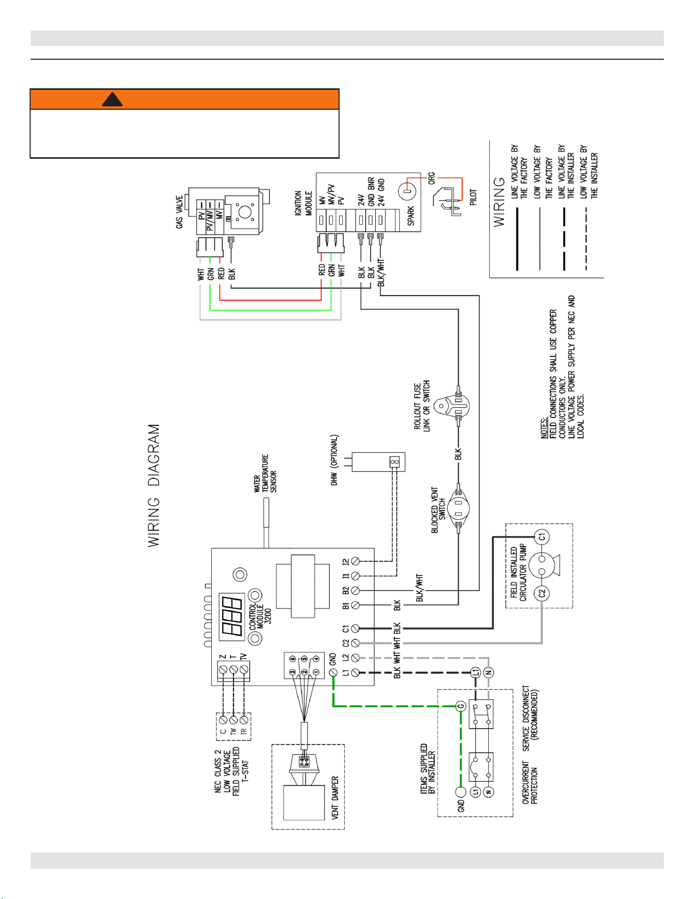
10 - WIRING DIAGRAM
Figure 12 - Integrated High Limit Electronic Ignition Control
WARNING
Modication, substitution or elimination of factory
equipped, supplied or specied components may
result in personal injury or loss of life.
!
PN 240013340 Rev. C [12/02/2022]

21
11 -GENERAL INSTRUCTIONS
FILLING SYSTEM WITH WATER
• Close air vents on all radiation units. Open valves to
these units.
• Verify boiler and expansion tank drain valves are closed.
• Air bleed screw on tank drain tting should be closed.
• Open valve in line from boiler to expansion tank. Open
water inlet to your boiler and leave it open. Start with
lowest radiation unit. Open air vent on this unit. When
all air has escaped and water starts to ow from vent,
close it.
• Go to next radiation unit, and repeat this process.
Repeat until you have covered every radiation units in
the system (ending up at highest unit in system).
• If your units have automatic vents, manual venting is
unnecessary but it will speed up the proper lling of
your system.
• If your system is closed expansion tank system, you
may leave it open to rell system automatically as
needed.
• Check temperature pressure gauge. Note position of
hand indicating pressure. This should be between 10
and 15 psi. Any lowering of this movable hand below 10
psi. Will indicate loss of water due to leakage. Automatic
ll valve should compensate for this. Instructions are
packaged with the valve.
WARNING
Adding water to hot boiler may result in heat
exchanger failure. Before lling boiler verify heat
exchanger is not hot. Failure to follow these
instructions could result in death or serious injury.
!
PN 240013340 Rev. C [12/02/2022]
22
12 - LIGHTING INSTRUCTIONS
1. STOP! Read the safety information above.
2. Set the thermostat to lowest setting.
3. Turn o all electric power to the appliance.
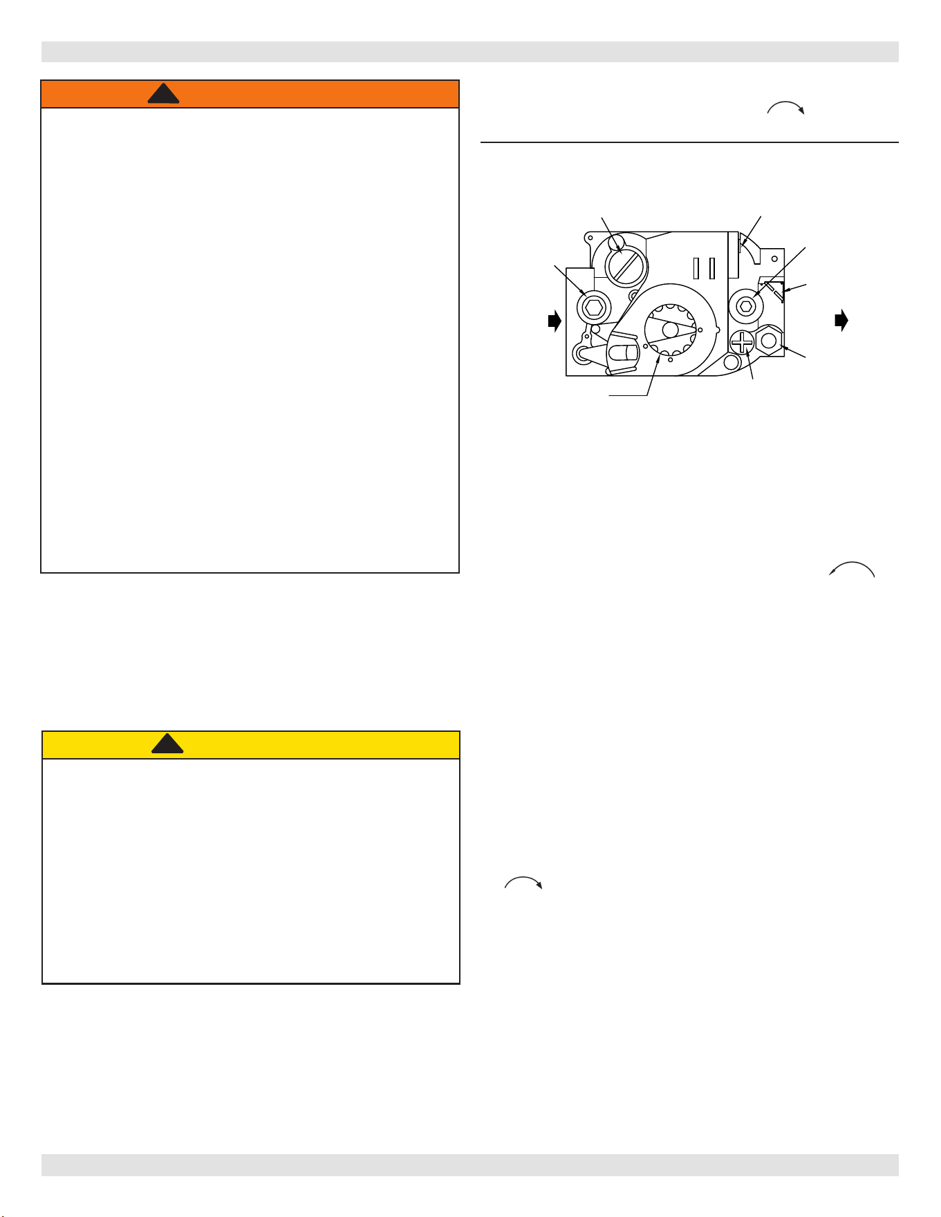
4. This appliance is equipped with an ignition device which
automatically lights the pilot. Do not try to light the pilot
by hand.
OFF
ON
INLET
GAS CONTROL
KNOB
PILOT ADJUSTMENT
(UNDER CAP SCREW)
PILOT
OUTLET
OUTLET
WIRING
TERMINALS (2)
INLET
PRESSURE
TAP
TERMINALS
(2)
GROUND
PRESSURE
TAP
PRESSURE REGULATOR
ADJUSTMENT
(UNDER CAP SCREW)
OUTLET
5. Remove lower front panel.
6. Rotate the gas control knob clockwise to “OFF”.
7. Wait ve (5) minutes to clear out any gas. Then
smell for gas, including near the oor. If you smell
gas, STOP! Immediately call your gas supplier from a
neighbor’s phone. Follow the gas supplier’s instructions.
If you don’t smell gas, go to next step.
8. Rotate gas control knob counterclockwise to
“ON”.
9. Replace lower front panel.
10. Turn on all electric power to the appliance.
11. Set thermostat to desired setting.
12. If the appliance will not operate, follow the instructions
“To Turn O Gas To Appliance” and call your service
technician or gas supplier.
TO TURN OFF GAS TO APPLIANCE
1. Set the thermostat to lowest setting.
2. Turn o all electric power to the appliance if service is
to be performed.
3. Push in gas control knob slightly and turn clockwise
to “OFF” Do not force.
WARNING
If you do not follow these instructions
exactly, a re or explosion may result
causing property damage, personal injury
or loss of life.
• This appliance is equipped with an ignition device
which automatically lights burner. Do NOT try to
light this burner by hand.
• Before operating smell all around appliance area
for gas. Be sure to smell next to oor because
some gas is heavier than air and will settle to the
oor.
• Use only your hand to turn the gas shuto
valve. Never use tools. If valve will not turn
by hand, do not try to repair it, call a qualied
service technician. Force or attempted repair may
result in re or explosion.
• Do not use this appliance if any part has
been under water. Immediately call a qualied
service technician to inspect appliance and to
replace any part of control system and any gas
control which has been under water.
!
LIGHTING PROCEDURE FOR BOILER WITH
INTERMITTENT PILOT SYSTEM
For Your Safety, Read Before Operating!!
A. This appliance is equipped with an ignition device
which automatically lights the pilot. Do not try to light
appliance by hand.
CAUTION
WHAT TO DO IF YOU SMELL GAS
• Do not try to light any appliance.
• Do not touch any electrical switches; do not use
any phone in your building.
• Immediately call your gas supplier from a
neighbor’s phone. Follow the gas supplier’s
instructions.
• If you cannot reach your gas supplier, call the re
department.
!!
Figure 13 - Automatic Gas Valve
PN 240013340 Rev. C [12/02/2022]
23
13 - OPERATING YOUR BOILER
AUTOMATIC GAS VALVE
Automatic Gas Valve opens or closes according to heat
requirements of thermostat and temperature limit control.
It closes if pilot goes out. Each individual control must be
operating correctly before any gas can pass to burners. Any
one control can hold gas supply from burner regardless of
demand of any other control.
SAFETY PILOT
Safety Pilot prevents ow of gas to burner if pilot goes out,
or will not ignite.
GAS VALVE SAFETY SHUTDOWN TEST
Ignition system safety shuto device must be tested after
placing boiler in operation.
RELIGHT
Electric and gas shall be o for 5 minutes before relighting.
THERMOSTAT
Keep it set at desired room temperature. If windows are to
be opened or heat is not needed, move thermostat pointer
to lower setting.
NOTICE
In event of failure of any component, system will
not operate or will go into safety lockout. System
is completely self-checking. On every call for heat,
each component must be functioning properly to
permit operation. Safety lockout system has to be
reset by turning thermostat to lowest setting for
one minute, then back to normal setting.
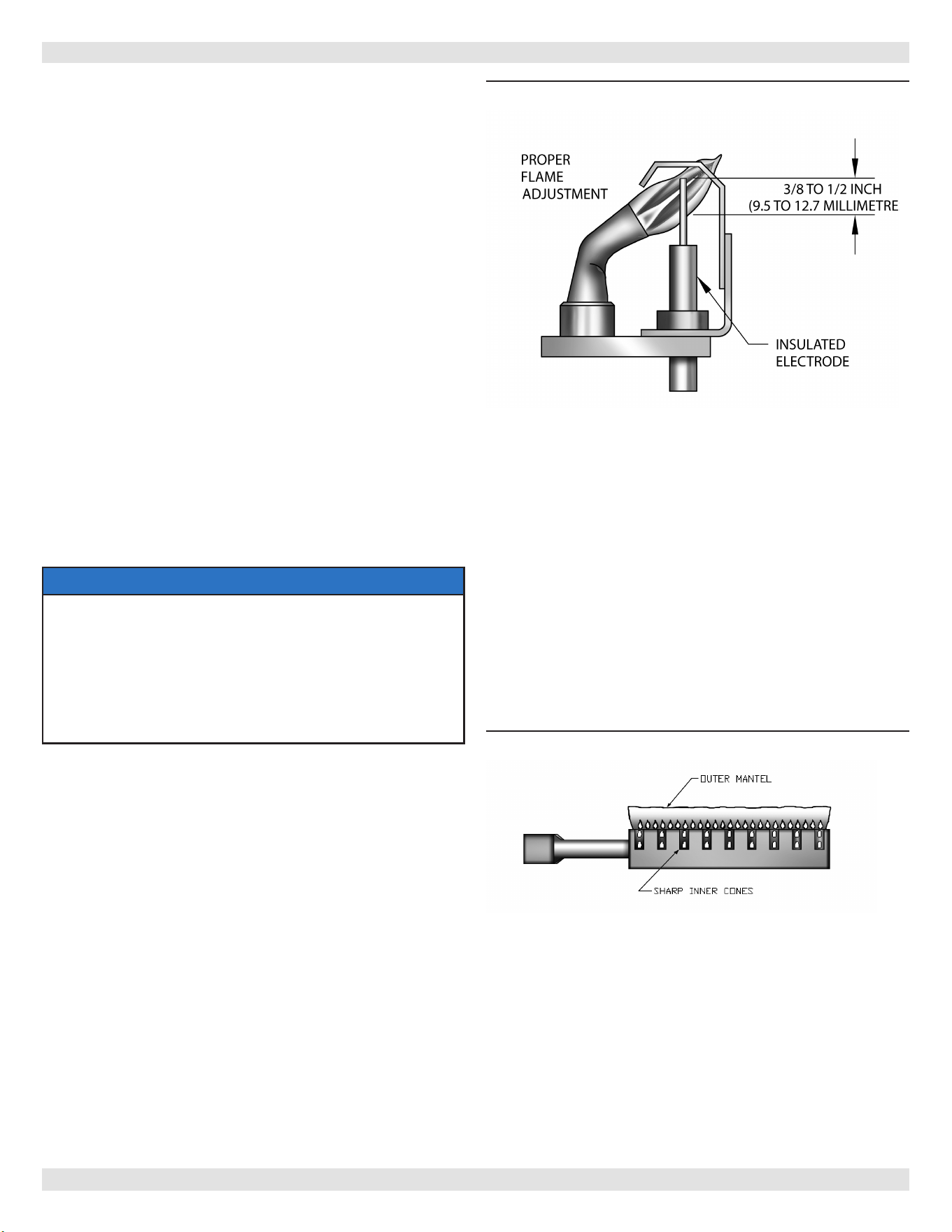
ADJUST PILOT BURNER
Pilot ame should surround 3/8” to 1/2” of the pilot sensor.
See Figure 14. If ame needs adjusting, do it as follows:
1.
Remove screw cover over pilot adjusting screw.
2.
Insert small screwdriver and adjust ame as needed.
Turn screw counterclockwise to increase ame, clockwise
to decrease.
3.
Replace screw cover over pilot adjusting screw.
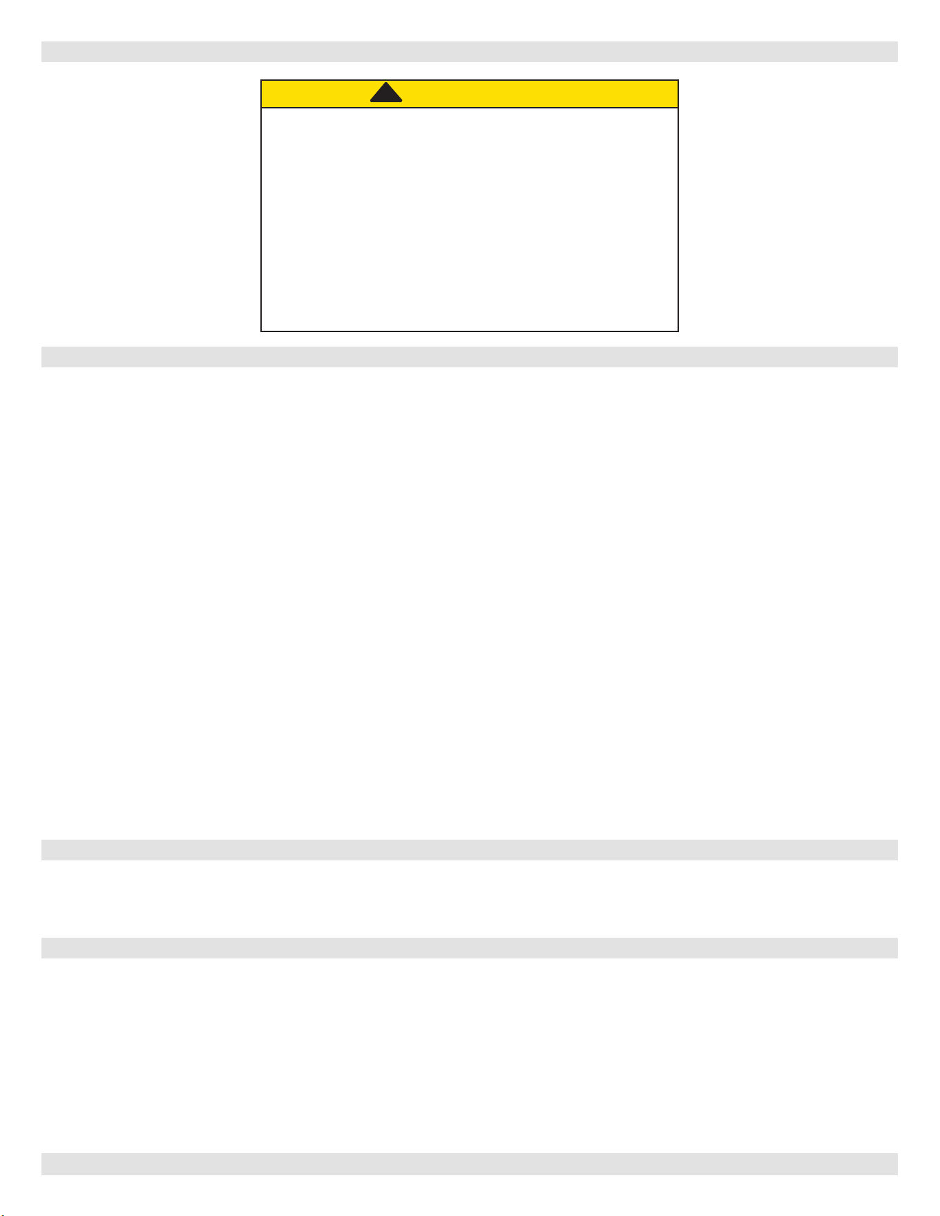
MAIN BURNER(S)
• Main burners do not require primary air adjustment and
are not equipped with primary air shutters.
• Main burner ames form sharp blue inner cones in softer
blue outer mantel, with no yellow.
• Pus of air from blowing on ame or stamping on oor
will cause ames to turn orange momentarily. This is
not unusual. Remain still when observing main burner
ames.
• If ame appearance is not correct, check main burner
orices, burner throat and ame ports for dust and
lint obstruction. It may be necessary to remove rollout
shield to observe main burner ames. Replace rollout
shield after observation. Refer to Figure 15.
Figure 15 - Burner
ADJUST LIMIT CONTROLS
Instructions for each control are included with controls.
Settings can be changed. Refer to Appendix A page 29 for
information.
Figure 14 - Pilot Flame
PN 240013340 Rev. C [12/02/2022]

24
CHECK THERMOSTAT OPERATION
A. When set above temperature indicated on
thermostat, boiler should ignite.
B. Verify thermostat turns boiler o when room
temperature reaches selected setting and starts
boiler operating when room temperature falls a
few degrees.
C. After setting limit control to limit setting, check to
see if it shuts o gas supply to burners. Turn your
thermostat up to call for heat and let boiler run
until temperature of water reaches limit setting.
Gas valve should shut o and circulator running
until thermostat is satised, or water cools enough
to restart burners through limit control.
D. Set thermostat for desired temperature. Conditions
in your home and location of thermostat will govern
this setting.
For Control Functions and Settings see Appendix A
13 - OPERATING YOUR BOILER- SYSTEM START-UP
PN 240013340 Rev. C [12/02/2022]

25
Table 6 - Troubleshooting
Burner Will Not Fire
No or Insucient Domestic
Hot Water
If installed with indirect water heater, insure switch controlling indirect water heater is properly
connected to I1-I2 (see wiring diagram). This insures domestic water calls are prioritized.
If I1-I2 is not used, turn Economy Feature OFF.
House will not get or stay
warm
1.
Check for air bound radiators.
2.
Check thermostat settings including heat anticipator settings (common on non-digital
thermostats.
3.
Check Economy settings. Economy feature, much like outdoor reset controls, lowers
average boiler temperature, can slow or prevent the house from coming up to
temperature. Move to lower setting.
13 - OPERATING YOUR BOILER
PN 240013340 Rev. C [12/02/2022]
26
EQUIPMENT AND OPTIONAL ACCESSORIES - WHAT THEY DO
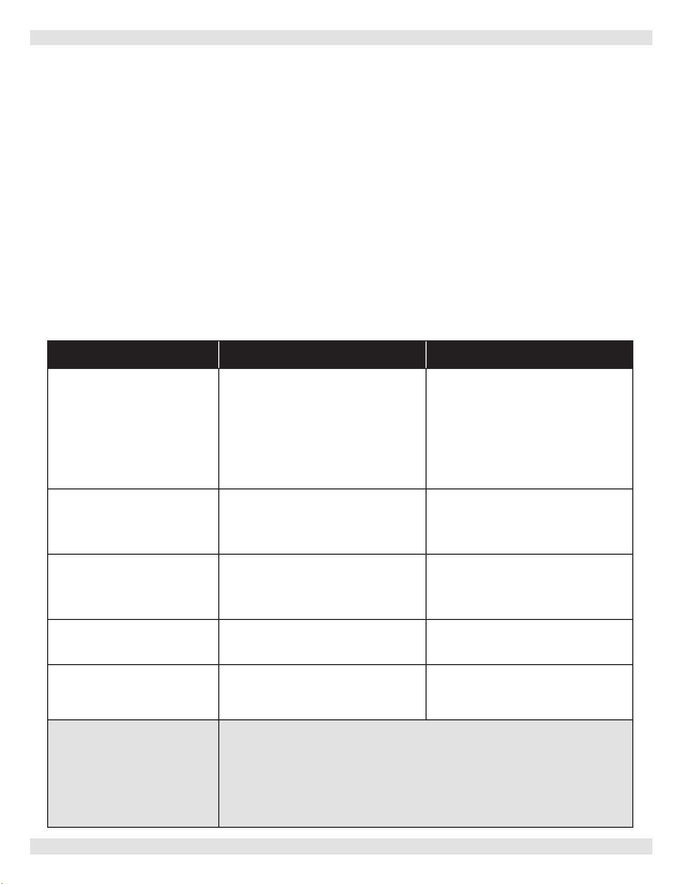
14 - SERVICE HINTS
You may avoid inconvenience and service calls by checking these points before you call for service.
Possible Cause What to do
Thermostat is not set correctly Reset thermostat above room temperature
Burner is not operating properly Check ame. If it is yellow, burner is not getting enough air.
Or, if ame is blue and noisy and seems to lift o burner,
burner is getting too much air. Contact your service technician.
No electric power to boiler Check over current protection. Verify electric power supply circuit is
“ON”.
Controls out of adjustment Reset according to instructions.
Radiators not heating Open radiator vents to expel air. Check ow control valve (if
used). It may be in closed position.
Circulating pump not running Check over current protection. Check relay operation.
Poor electrical contact Check all control terminals and wire joints.
Rollout switch blown Have your service agent check heat exchanged for blockage.
Replace rollout switch with exact replacement.
Blocked vent blown Have your service agent check venting system and chimney
for blockage, or down draft condition. Reset blocked vent.
Vent damper not operating Consult troubleshooting guide
Possible Cause What to do
Gas input amount is incorrect Contact your service agent.
Possible Cause What to do
Dirt on seat Open valve manually. Allow water to run and clear valve seat.
Water logged expansion tank Drain tank, see instructions.
IF YOUR SYSTEM IS NOT HEATING OR NOT GIVING ENOUGH HEAT . . .
IF BURNER IS NOISY . . .
RELIEF VALVE LEAKING . . .
HAVE YOUR SERVICE AGENT CHECK ANY PROBLEM YOU ARE UNABLE TO CORRECT.
CAUTION
WHAT TO DO IF YOU SMELL GAS
• Do not try to light any appliance.
• Do not touch any electrical switch; do not use
any phone in your building.
• Immediately call your gas supplier from a
neighbor’s phone. Follow the gas supplier’s
instructions.
• If you cannot reach your gas supplier, call the re
department.
!!
PN 240013340 Rev. C [12/02/2022]

27
15 - MAINTAINING YOUR BOILER
BURNERS
Beginning of heating season visually check pilot and main
burner ames. See Page 23.
SAFETY RELIEF VALVE
Refer to page 7 for important information. To test safety
relief valve refer to valve manufacturer’s instructions
packaged with relief valve. Call Technical Support if
manufacturer’s instruction are not located.
EXPANSION TANK
Tank may become waterlogged, or may receive excess
of air. Frequent automatic opening of safety relief
valve indicates water logging. High boiler temperature
accompanied by unusually low radiation unit temperature
(and “knocking”) indicates excess air in tank.
To correct:
1.
Close valve between boiler and tank. Drain tank until
empty.
2.
Check all tank plugs and ttings. Tighten as necessary.
3.
Open valve between boiler and tank. Water will rise to
normal height in tank if you have automatic ll valve
(otherwise, manually rell system).
BOILER FLUE PASSAGES
Recommend following checked annually by qualied service
agent.
• ue passages
• burner adjustment
• operation of controls
Before start of each season (or whenever system has been
shut down for some time) recheck whole system for leaks
and recheck boiler and vent pipe for leaks. Replace or patch
any boiler seals that are faulty.
VENT PIPE
Venting and piping should be checked at least once a
season. If vent piping shows any sign of leaking, replace
immediately.
WATER SYSTEM
If system is to remain out of service during freezing
weather, always drain it completely (water left in to freeze
will crack pipes and/or boiler).
CLEANING YOUR BOILER AND BURNERS
Flue passages between sections should be examined yearly
and cleaned if necessary.
To clean:
• Remove burners, pilot, and vent pipe.
• Remove top and front jacket panels.
• Remove two screws attaching intermediate front panel
to left and right side jacket panels.
• Remove draft diverter and intermediate front panel
together.
• Carefully remove cerafelt gasket strips.
• Clean passageways between sections with exible
handle wire brush. Remove dirt from bottom of boiler
and from between sections by vacuuming.
• Verify all ame ports in burners are open and clear.
Shake out or blow out all loose dirt in burners.
• Reseal seams between adjacent sections as necessary
with 400
°
F RTV silicone sealant.
• Reassemble all parts.
• Verify tightness of pilot connections and condition of
burner ames after reassembly. See Figures 15 and 16,
pages 20.
• Verify vent pipe connections to chimney are secure and
no obstructions are present.
HOUSEKEEPING
• Keep boiler area clear and free from combustible
materials, gasoline and other ammable vapors and
liquids.
• Keep boiler area clear of debris and other materials
obstructing ow of combustion and ventilation air.
PN 240013340 Rev. C [12/02/2022]
28
17 - BOILER RATINGS AND CAPACITIES
PN 240013340 Rev. C [12/02/2022]
16 - BOILER RATINGS AND CAPACITIES
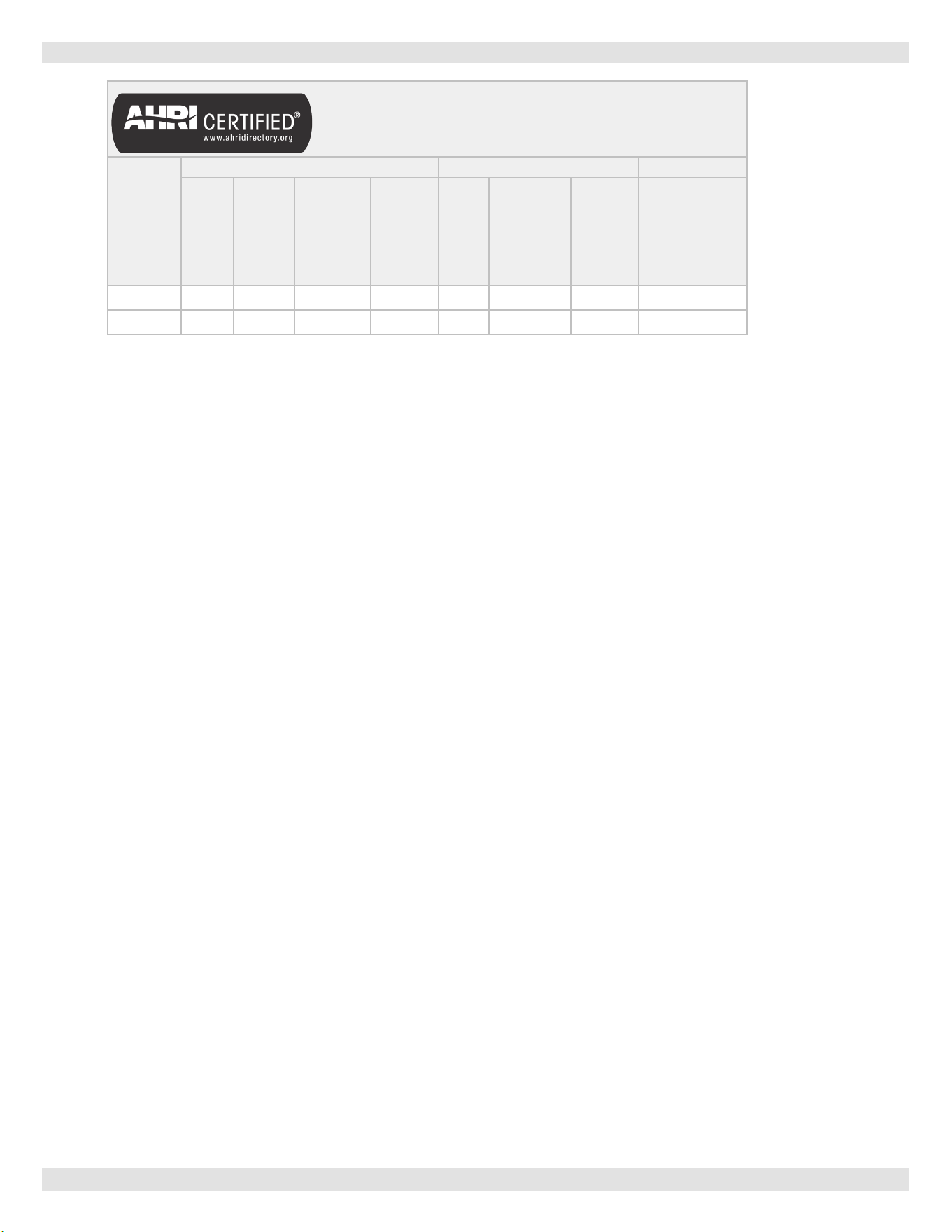
Table 2 - Ratings and Capacities
BOILER
MODEL
NUMBER
(1)
† NATURAL GAS † PROPANE GAS AFUE
Input
(3)
Mbh
Heating
Capacity
(3)
Mbh
(2)
NET AHRI
RATING
Water,
(3)
Mbh
*HIGH
ALTITUDE
INPUT
(3)
Mbh
INPUT
(3)
Mbh
HEATING
CAPACITY
(3)
Mbh
NET AHRI
RATING
INTERMITTENT
IGNITION WITH
VENT DAMPER
15C-8D 262 221 192
236
245 208 181 84.0
15C-9D
299 252 219
269
280 237 206 84.0
†
Input rating for sea level to 2,000 ft. (610m) above sea level.
• United States, over 2000 ft (610m) above sea level. Reduce input rate 4% for every 1000 ft (304m) above sea
level.
+ Heating Capacity based on D.O.E. (Department of Energy) test procedure.
(1)
Add model number sux ‘P’ for Propane.
(2)
Net AHRI Water rating shown based on piping and pickup allowance of 1.15. Consult manufacturer before selecting
boiler for installations having unusual piping and pickup requirements, such as intermittent system operation,
extensive piping systems, etc.
(3)
Mbh = 1,000 Btuh = British Thermal Unit Per Hour
- Ratings marked “Net AHRI Ratings” indicate amount of remaining heat input used to heat radiation or terminal units.
Net AHRI Ratings shown are based on allowance of 1.15 in accordance with factors shown on AHRI Standard as
published by The Hydronics Institute.
- Selection of boiler size should be based upon “Net AHRI Rating” being equal to or greater than calculated heat loss of
the building.
- Consult manufacturer before selecting boiler for installations having unusual piping and pickup requirements.
BOILERS FOR USE AT HIGH ALTITUDE
Boiler is factory equipped for use at altitudes of 0-2,000 feet above sea level.
For use at altitudes above 2,000 feet above sea level, input ratings are reduced by change in main burner orice size.
For altitudes above 2,000 feet above sea level, input ratings should be reduced at rate of 4% for each 1,000 feet above
sea level. Consult National Fuel Gas Code, ANSI Z223.1/NFPA 54, or manufacturer for correct orice sizing information.
In Canada, a high altitude conversion kit is available to convert to altitudes of 2,000 to 4,500 feet above sea level. Please
consult your dealer.
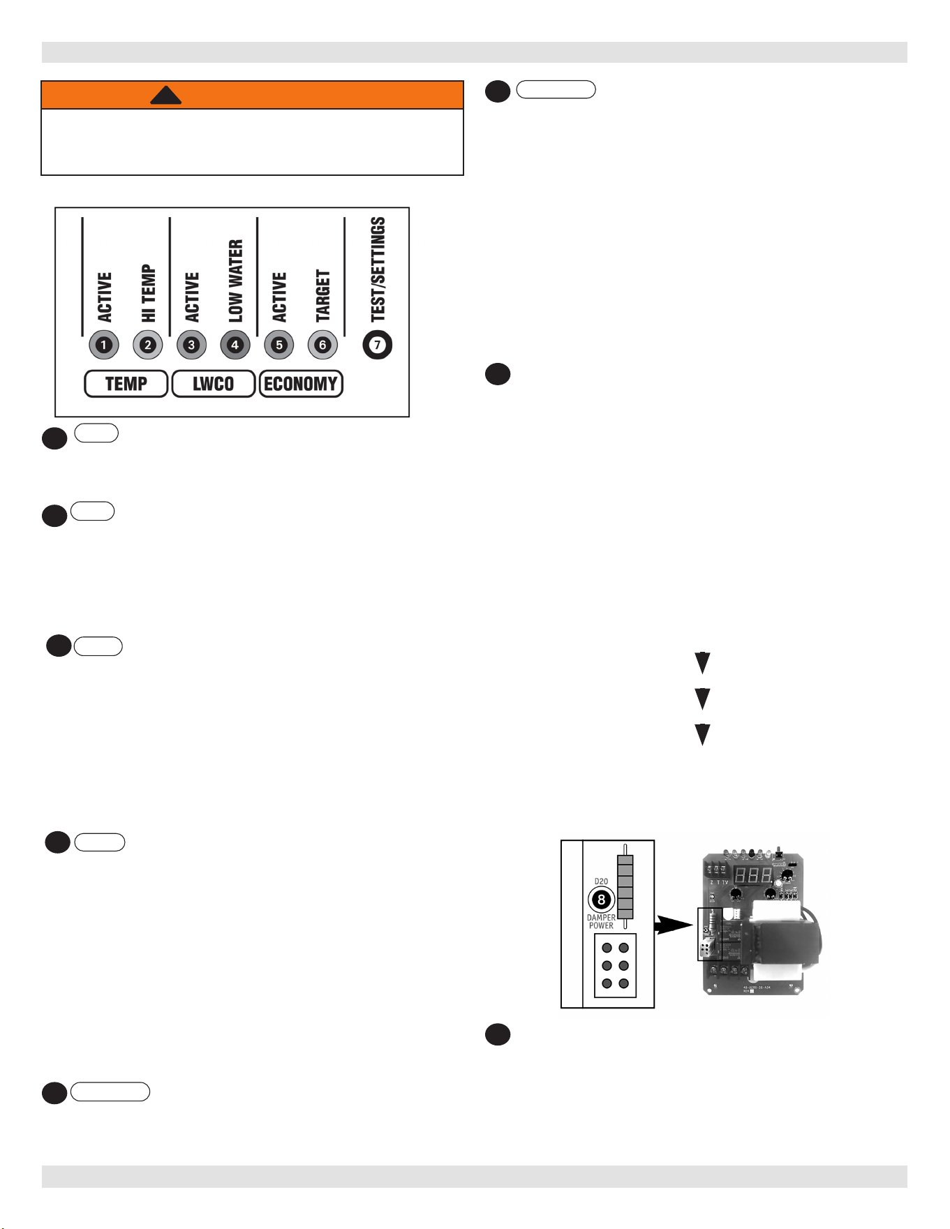
29
TEMP ACTIVE Indicates the Fuel Smart HydroStat
control is powered and the temperature function is
active.
TEMP HI TEMP Illuminates when the boiler water
temperature reaches the high limit setting. It will
remain lit until the water temperature falls 10°. The
Fuel SmartHydroStat prevents burner operation while
this LED is on. See Dierential explanation on page 6
of Hydrolevel Manual.
LWCO ACTIVE Indicates the low water cut-o
(LWCO) function of the Fuel Smart HydroStat is active.
When the control is installed with a Hydrolevel Electro-
Well, this LED will be on at all times when the control
is powered.
IMPORTANT: If the control is installed with a well
other than the Electro-Well, this LED will not illuminate
indicating the control is not providing low water cut-o
functionality.
LWCO LOW WATER Indicates the boiler is in
a low water condition. The HydroStat control will
prevent burner operation during this condition. If the
LOW WATER light is blinking, the control has been
programmed to provide lockout protection in the event
a low water condition is detected. (see Manual Reset
Low Water Cut-O on page 8 of Hydrolevel manual).
Pressing the TEST/SETTINGS button will reset the
control.
IMPORTANT: The system must be checked by a
qualied heating professional prior to resuming
operation.
ECONOMY ACTIVE Indicates the Thermal Targeting
function is active and the Fuel Smart HydroStat will
reduce boiler temperature to conserve fuel. The
Economy feature is activated using the ECONOMY dial.
APPENDIX A - CONTROL FUNCTION
ECONOMY Target When the Economy feature is
active, the Fuel Smart HydroStat continually sets
target temperatures below the high limit setting
to maximize fuel eciency. When the boiler water
reaches the target temperature, the LED illuminates
and the burner will shut down. The boiler water will
continue to circulate and heat the house as long as the
thermostat call continues. The LED will stay lit until
the boiler temperature drops below the dierential set
point at which point the boiler will be allowed to re
again.
See Dierential explanation on page 6 of Hydrolevel
Manual.
NOTE: This LED illuminates regularly during normal
boiler operation
TEST/SETTINGS Button
To Test Low Water Cut-O: Press and hold the Test/
Settings button for 5 seconds. The display will read
LCO. LWCO TEST LCO
The red Low Water light should illuminate and the
burner circuit (B1 and B2) should de-energize. NOTE:
The control must be installed with a Hydrolevel Electro-
Well for low water cut-o functionality (see page 2 of
Hydrolevel manual for more details).
To View Current Settings: Press and release the
Test/Settings Button in short intervals to sequentially
display the following settings:
HIGH LIMIT SETTING HL
LOW LIMIT SETTING LL
ECONOMY SETTING ECO
CURRENT TARGET TEMPERATURE 000
The display will return to boiler temperature (default) if
Test/Settings Button in not pressed for 5 seconds.
WARNING
Burn and scald hazard. Do not add water until boiler
has fully cooled. Failure to follow these instructions
could result in death or serious injury.
!
7
1
2
3
4
6
5
8
DAMPER POWER LED
Indicates the control is energizing the vent damper.
For applications where the vent damper is not plugged
into the HydroStat, the LED indicates the burner circuit
(B1 - B2) is powered. LED will blink when power is sent
to the Vent Damper and will turn solid when power
returns from the end switch.
PN 240013340 Rev. C [12/02/2022]
30
A-1. Intermittent Pilot
Ignition System Checks
STEP 1: Check ignition cable.
a. Verify ignition cable does not make contact with
metal surfaces.
b. Verify only factory supplied Ignition cable (or
approved replacement) is used.
c. Verify connections to ignition module and igniter or
igniter-sensor are clean and tight.
d. Verify ignition cable provides good electrical
continuity.
STEP 2:
Verify ignition system grounding. Nuisance shutdowns are
often caused by poor or erratic grounding.
Common ground is required for module and pilot burner/
igniter sensor.
‒ Check for good metal-to-metal contact between pilot
burner bracket and the main burner.
‒ Check ground lead from GND (BURNER) terminal
on module to pilot burner. Verify connections are
clean and tight. If wire is damaged or deteriorated,
replace with No. 14-18 gauge, moisture-resistant,
thermoplastic insulated wire with 105°C [221°F]
minimum rating.
‒ Check ceramic ame rod insulator for cracks or
evidence of exposure to extreme heat, which can
permit leakage to ground. Replace pilot burner/
igniter sensor and provide shield if necessary.
‒ If ame rod or bracket is bent out of position,
restore to correct position.
If this LED is blinking and the burner is not ring:
Make sure the plug connection (or jumper, on boilers where
vent damper plug is not used) is secure.
Make sure the plug connection at the vent damper end is
secure and oriented correctly.
Make sure damper motor turns.
Verify the damper end switch has closed
DANGER
Carbon Monoxide Hazard: If the burner res
when the vent damper is not fully opened or there is
any other blockage in the ue, dangerous ue
products, such as carbon monoxide, will escape into
the living space causing severe personal injury or
death. The ue as well as the vent damper must be
checked for proper operation before allowing the
system to operate.
!
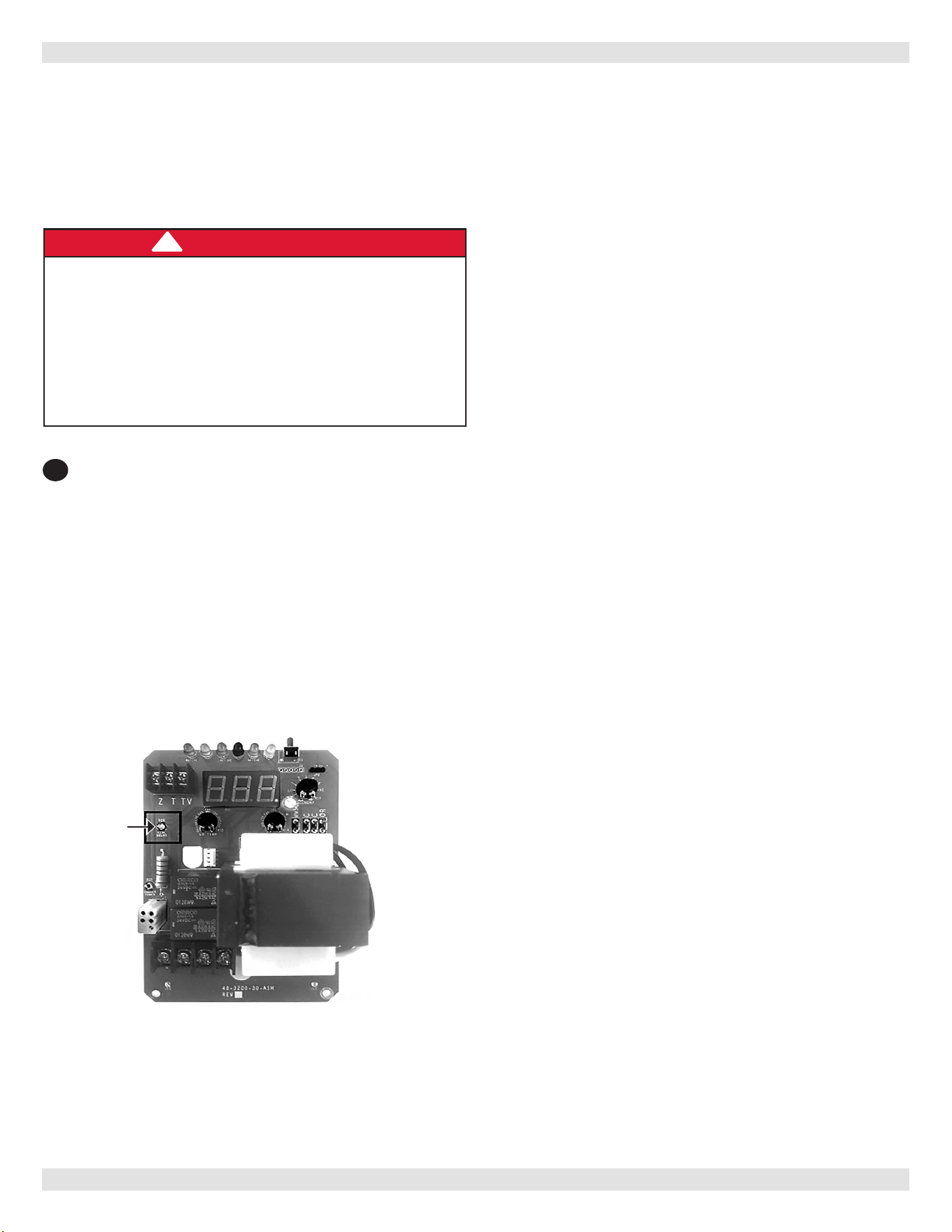
Circ Delay LED
The blue “circ delay” LED lights to indicate the heating
circulator (terminal C1) is being held o.
To minimize condensation on the boiler heat exchanger
and in the ue due to low water temperature, the
circulator is not energized until the boiler water
temperature reaches 125°F.
At that point, the circulator will be powered on and the
LED will turn o.
If the boiler water temperature falls below 115°F the
circulator will turn o again and the LED will illuminate
until the temperature reaches 125°F again.
9
APPENDIX A - CONTROL FUNCTION
Blue
“Circ Delay”
Light
PN 240013340 Rev. C [12/02/2022]
31
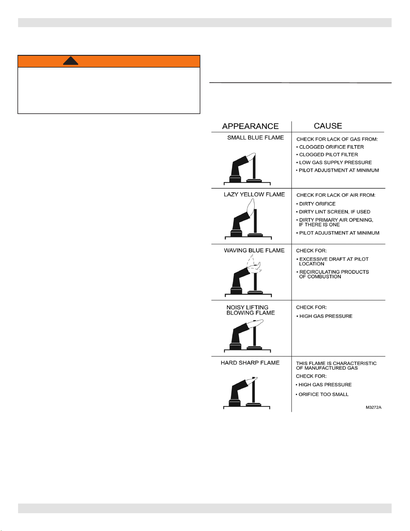
Figure A-1 - Troubleshooting Pilot Flame
STEP 3: Check spark ignition circuit.
WARNING
Electrical shock hazard. Ignition circuit generates
over 10,000 volts. Turn OFF electrical power
supply at service panel before making electrical
connections. Failure to do so could result in death
or serious injury.
!
Energize module and listen for audible sparking noise.
When operating normally, there should be a buzzing noise
that turns on and o twice per second for duration of 1–7
seconds depending on model.
Reconnect ignition cable.
STEP 4: Verify pilot and main burner light-o.
1.
Initiate call for heat. Turn thermostat above room
temperature. Ignition sequence may be delayed by
thermal purge up to 2 minutes.
2.
Watch pilot burner during ignition sequence.
‒ Verify ignition spark stops within a few seconds after
pilot is lit.
‒ Verify Main burner lights within a few seconds of
pilot lighting
a. Check pilot ame. Verify it is blue, steady and
envelops 3/8 to 1/2 in. [10 to 13 mm] of ame
rod. See Figure A-1 for possible ame problems
and causes.
b. If necessary, adjust pilot ame by turning pilot
adjustment screw on gas control clockwise to
decrease or counterclockwise to increase pilot
ame. Following adjustment, always replace pilot
adjustment cover screw and tighten rmly to
assure proper gas control operation. Figure 13,
page 22.
3.
If pilot does not stay lit, ensure adequate ame current
as follows.
‒ Turn o boiler at circuit breaker or fuse box.
‒ Clean ame rod with emery cloth.
‒ Verify electrical connections are clean and tight.
Replace damaged wire.
‒ Check for cracked ceramic insulator, which
can cause short to ground, and replace pilot if
necessary.
‒ Set temperature below room set-point to end call for
heat.
4.
Recheck ignition sequence as follows:
a. Adjust thermostat above room temperature.
b. Verify ignition sequence at burner.
APPENDIX A - CONTROL FUNCTION
Correct Pilot Flame: 3/8 to 1/2 inch in ame.
See Figure 14, Page 23.
PN 240013340 Rev. C [12/02/2022]
32
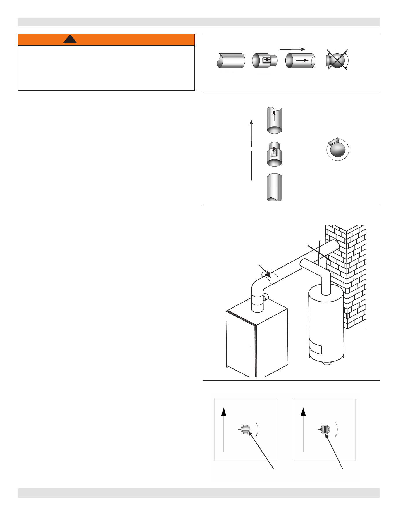
1.
Verify only boiler is serviced by Vent Damper. Figure 2.
2.
Clearance of 6 inches (152 mm) between Vent
Damper and combustible material shall be maintained.
Allow additional clearance for service of Vent Damper.
3.
Vent Damper shall be in the open position when
appliance main burners are operating.
4.
Vent Damper position indicator must be in visible
location following installation.
APPENDIX B - VENT DAMPER INSTALLATION
B.1 Damper Installation
Follow Damper installation instructions provided with
damper. See Figure 1a & 1b.
Figure 1a - Horizontal Installations
Figure 2 - Alternate Vent Damper Installation
Check vent damper and all ue product carrying areas of
boiler annually for deterioration from corrosion or other
sources. Contact your service agent for repairs.
Check Vent Damper Operation as follows:
1.
When boiler is o, check vent damper position
indicator points to closed position. See Figure 3.
2.
Turn thermostat or controller up to call for heat and
check vent damper indicator points to open position
See Figure 3.
3.
Turn thermostat or controller down again and check
damper position indicator returns to closed position.
4.
Return thermostat to desired position.
5.
Place vent damper in open position to permit burner
operation by using “HOLD DAMPER OPEN” switch,
located on damper controller.
6.
Thermostat controls burner ring as before, while
damper remains open.
7.
DO NOT turn damper open manually, motor damage
will result.
8.
Set switch to “AUTOMATIC OPERATION” to close vent
damper during burner o cycle.
9.
For further information, and for vent damper
troubleshooting guide, refer to manual packaged with
vent damper.
Flue Gas
Flue Gas Flow
OPEN
CLOSED
ROTATION
CLOSED
OPEN
ROTATION
Damper Closed
Damper Open
Open and Closed Positions Shown
B.2 Vent Damper
WARNING
Asphyxiation, burn hazard. Improper operation of
vent damper may result in serious injury or death
due to re or to asphyxiation from poisonous gases
such as carbon monoxide which is odorless and
invisible.
!
Figure 3 - Vent Damper Position Indicator
Do Not
Install Here
Do not install Vent
Damper within
6" (152mm) of
combustible material
Install Damper Here
Water
Heater
Chimney
Boiler
To Boiler
Vent Damper
To Chimney
NO
NO
YES
YES
Flow
Install vent damper with actuator to sides of
vent only. Do not mount above or below vent
To Chimney
Vent
Damper
To Boiler
Actuator may be
installed in any
position
Flow
Figure B-1b - Vertical Installations
PN 240013340 Rev. C [12/02/2022]
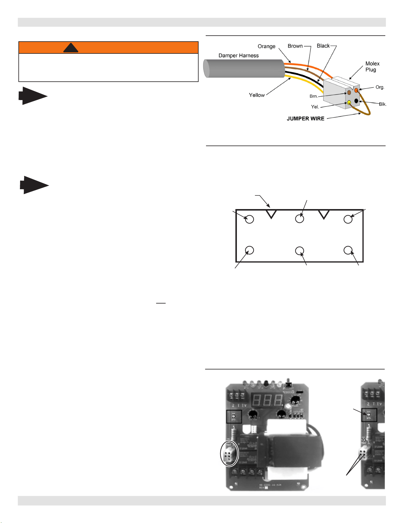
33
APPENDIX B - VENT DAMPER INSTALLATION
B.3 Vent Damper Harness - Molex Plugs
WARNING
Follow all instructions regarding safety operational
controls in this manual. Failure to follow these
instructions could result in death or serious injury.
!
Control End of wiring harness
Hold plug in hand with wiring harness behind Molex with
“V” slot on top. Verify wires colors are in proper position
OPEN
Black
"V" Slot
Yellow
Brown
Orange Black
1.
Disconnect thermostat wires.
2.
Conrm the Molex plugs on each end of the damper
harness are wired and operating properly. See Figures
4 and 5.
Damper end of wiring harness:
A. Hold plug in hand with wiring harness behind Molex
with “V” slot on top. Verify wire colors are in
proper position.
B. Take reading across brown and black wires in Molex
plug, using test meter set for AC volts. 24 volts
should be present.
i. IF NOT, source of the problem is not in
damper; check line voltage and 24 volt supply.
ii. If 24 volts is present across brown and black,
continue to step iii.
iii. Reconnect thermostat wires and turn up heat
setting.
iv. Check voltage across black and orange wires
in Molex plug. 24 volts AC should be present:
• IF NOT, source problem is not the damper.
• If 24 volts is present continue on to step v.
v. Place jumper wire across orange and yellow
wires in Molex plug (see Figure 4). This will
create bypass of the damper, boiler should
then ignite.
• If boiler ignites: Go to section B.4 "Vent
Damper Troubleshooting Guide".
• If boiler does not ignite: Problem is not the
damper. Go to Damper harness Molex on
Aquastat, Step C.
NOTE: Prior to replacing the damper, be sure the
problem is not with wire connections between damper
and wiring harness.
Note
Damper wiring harness is made up of 4
individual colored wires, Brown, Black, Yellow,
and Orange. See Figure 4.
Check Molex Plugs on Vent Damper Harness:
Note
When servicing controls, all wires must be
labeled prior to disconnection. Wiring errors
can cause improper and dangerous operation.
Do not turn damper open manually or motor
damage will result.
Do not cut plug o of damper motor assembly
this will aect warranty coverage.
Figure 4
Verify Molex pins are fully seated in both
ends of Molex plugs
Figure 5
C. Remove damper harness from control. Jump Molex
connector on control board between two center
holes using ~ 18 ga. thermostat wire. See Figure 6
Check Molex Plugs on Vent Damper Harness:
i. If boiler ignites, replace damper harness
ii. If boiler does not light, check for 24 volts at
B1-B2 on aquastat. If no replace control.
iii. If 24 Volts are present Damper and Control
are ok. Check ignition module, rollout switch,
spill switch or gas valve.
Figure 6
Jumper two
center pins
Figure 1a - Horizontal Installations
Figure B-1b - Vertical Installations
Blue
“Circ Delay”
Light
PN 240013340 Rev. C [12/02/2022]
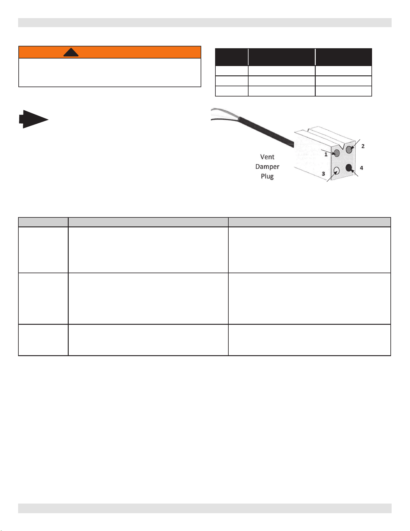
34
B.4 Vent Damper Troubleshooting Guide
Note
When servicing controls, all wires must be
labeled prior to disconnection. Wiring errors
can cause improper and dangerous operation.
Do not turn damper open manually or motor
damage will result and aect warranty coverage,
use the service switch.
Do not cut plug o of damper motor assembly
this will aect warranty coverage.
Problem Possible Cause Recommended Solution
NO POWER
Between 4 & 1
1. O on limit (120VAC)
2. Bad transformer
3. Loose or broken connections
4. Blown fuse or circuit breaker
5. Disconnect switch o
6. Harness not plugged into receptacle on aquastat
1. turn limit on
2. Replace transformer
3. Tighten, repair, or replace connection
4. Replace fuse or reset circuit breaker
5. Turn switch on
6. Plug harness in
NO POWER
Between 4 & 2
POWER
Between 4 & 1
When calling for
heat
1. Thermostat not calling for heat
2. Burned out heat anticipator
3. Loose or broken connections
4. O/On operating limit, pressure control or low water cut o
5. O/On blocked vent switch or ame roll out
1. Turn thermostat up to call for heat
2. Replace thermostat
3. Tighten, repair, or replace connection
4. Turn operating limit, pressure control, or low water cuto ON
5. Reset or replace switch
POWER
Between 4 & 1
Between 4 & 2
DAMPER OPEN
1. Loose or broken connection
2. Defective damper motor
1. Tighten, repair, or replace connection
2. Replace damper motor assembly
Vent Damper Troubleshooting
WARNING
Follow all instructions regarding safety operational
controls in this manual. Failure to follow these
instructions could result in death or serious injury.
!
24 VAC
Power
Power ON Damper Position
4 & 1 All times Open or Closed
4 & 2 Calling for Heat Open or Opening
4 & 3 During combustion Damper Open
Normal Sequence of Operation
APPENDIX B - VENT DAMPER INSTALLATION
Orange
Black
Brown
Yellow
PN 240013340 Rev. C [12/02/2022]
35
Company Address & Phone #Company Name & Tech InitialsService PerformedDate
PN 240013340 Rev. C [12/02/2022]

IMPORTANT
In accordance with Section 325 (f) (3) of the Energy Policy and Conservation Act, this boiler is
equipped with a feature that saves energy by reducing the boiler water temperature as the heating
load decreases. This feature is equipped with an override which is provided primarily to permit the
use of an external energy management system that serves the same function.
THIS OVERRIDE MUST NOT BE USED UNLESS AT LEAST ONE OF THE FOLLOWING CONDITIONS IS
TRUE:
• An external energy management system is installed that reduces the boiler water temperature as the heating load
decreases.
• This boiler is not used for any space heating
• This boiler is part of a modular or multiple boiler system having a total input of 300,000 BTU/hr or greater.
• This boiler is equipped with a tankless coil.
All specications subject to change without notice.
©2022 ECR International, Inc.
2201 Dwyer Avenue, Utica, NY 13501
Tel. 800 325 5479
www.ecrinternational.com