105X150mm
Klein Electronics, Inc. 2026
USER GUIDE

1
GO-KP Quick Start:
Perform the following steps to assemble your handheld radio:
• Charge the battery.
• Install the battery.
• Install the antenna.
• Install the belt clip.
• Turn on the radio.
• Select a channel.
• Install your audio accessory (if needed).
• Adjust the volume.
Charging the Battery
The radio is powered by a Li-lon battery. To protect the battery from damage and
comply with the warranty conditions, you can use only the charger provided with
the battery for charging. To maximize battery performance, it is recommended to
charge the battery for 10 to 12 hours before the first use.
Installing the Battery
Align the battery with the battery slot on the rear side of the radio. Push the
battery into the slot until it is fastened. Before removing the battery, turn off the
radio first. Press the battery fastener and then remove the battery.
Installing the Antenna
Turn off the radio, place the antenna into the installation hole, and turn the
antenna clockwise. To remove the antenna, turn the antenna anticlockwise.
Before removing the antenna, ensure that you have turned off the radio and
removed the universal interface cover. To replace the antenna, use a specified
antenna to replace the old one. Otherwise, your radio may be damaged.
Installing the Belt Clip
Align the screw holes on the belt clip with those on the rear side of the radio and
fasten the belt clip with screws.
Turning On the radio
Turn the volume/power knob clockwise until you hear a click sound. The radio
gives a short beep sound, indicating that the radio is successfully turned on.
Klein Electronics, Inc. 2026
32
Klein Electronics, Inc. 2026Klein Electronics, Inc. 2026
Selecting a Channel
Simply look at the knob with the numbers and rotate until you land onto the group
channel you desire. You should also hear the Voice Enunciation through the
speaker or earpiece of which channel you are on.
Installing an Audio Accessory
Remove the protective cover on the side of the radio and plug in your earpiece
or headset.
Adjusting the Volume
Turn the volume knob clockwise to turn up the volume. To turn down the volume
knob anticlockwise. Be careful if you are wearing an audio accessory!
Radio Control
Please read the following carefully:
• Radio Overview
• Programmable buttons
• PTT button
Radio Overview
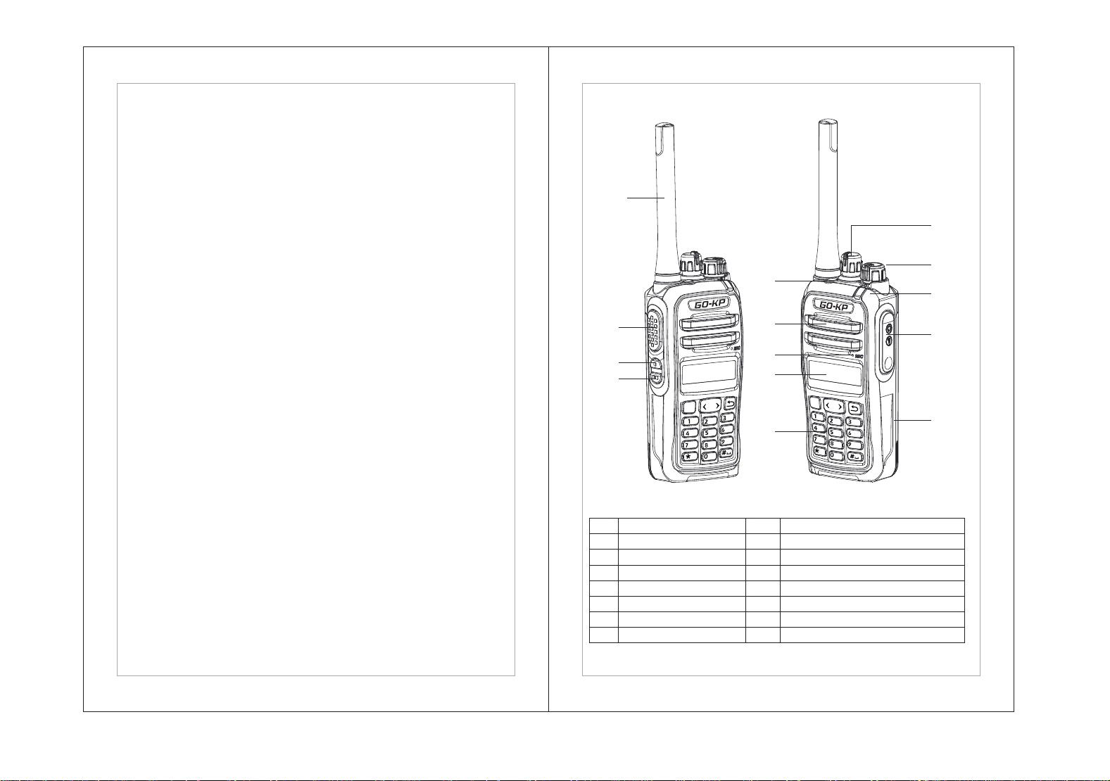
No. Feature No. Feature
1 Antenna 8 LCD
2 PTT button 9 Keypad
3 Side button PF1 10 Channel knob
4 Side button PF2 11 Volume/power knob
5 Top button PF3 12 LED indicator
6 Speaker 13 SP/MIC cover
7 MIC 14 Battery
OK
,.?
ABC
GHI
JKL
TUV
MNO
PQRS
CAPS
WXYZ
DEL
DEF
OK
,.?
ABC
GHI
JKL
TUV
MNO
PQRS
CAPS
WXYZ
DEL
DEF
1
5
11
13
14
12
10
9
6
8
7
2
3
4
54
Klein Electronics, Inc. 2026Klein Electronics, Inc. 2026
Side Button PF1/PF2 and Top Button PF3
These buttons can be programmed for certain functions by PC software. The
function features that can be programmed are listed below, you can active/
deactivate the function by a short press or a long press once the key is
programmed.
• Short press - Pressing and releasing immediately.
• Long press - Pressing and holding for the programmed duration
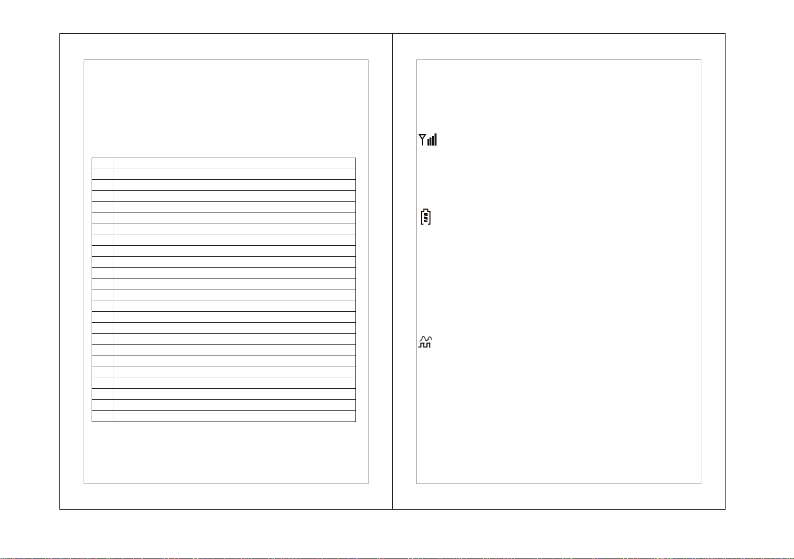
No.
1 All Alert Tones On/Off
2 Emergency On
3 Emergency Off
4 High/Low Power
5 Monitor
6 Nuisance Delete
7 One Touch Access 1
8 One Touch Access 2
9 One Touch Access 3
10 One Touch Access 4
11 One Touch Access 5
12 One Touch Access 6
13 Repeater/Talkaround
14 Scan On/Off
15 Tight/Normal Squelch
16 Vox On/Off
17 Zone Toggle
18 Lone Work On/Off
19 Companding
20 TX interrupt
21 Main Channel
22 Noise Reduction
23 Bluetooth Menu
Assignable functions on Side Button PF1/PF2 and Top Button PF3
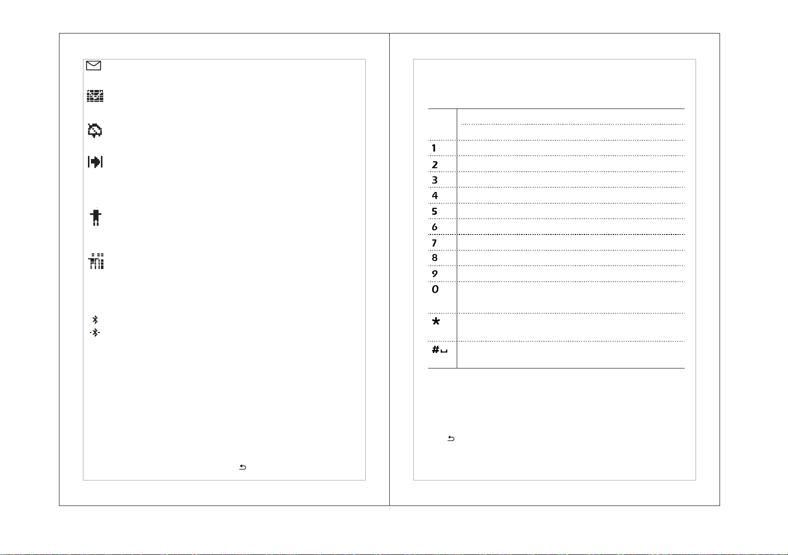
LCD Display Icons
The LCD display of your radio shows radio status, text entries, and menu entries.
The following are icons that appear on the status bar at the top of the radio's
display. lcons are displayed on the status bar, arranged left-to-right, in order of
appearance/usage and are channel specific. Canceled function icons will not be
displayed.
Received Signal Strength indicator
The number of bars displayed represents the radio signal strength. Four bars
indicate the strongest signal. This icon is only displayed while receiving.
Power Level
Radio is set at Low power or high power.
Battery
The number of bars (0-4) shown indicates the charge remaining in the battery.
if it is blinking the battery is low.
Narrow band
The current channel spacing is 12.5KHz (Analog narrow band or digital).
Channel Mode
The current channel mode is analog mode.
The current channel mode is digital mode.
The current channel mode is mixed mode.
CTCSS Tone
The current analog channel has a CTCSS tone.
DCS Tone
The current analog channel has a DCS tone
Scan
Scan feature is enabled.
LH
Z
N
CTC
DCS
A
D
76
Klein Electronics, Inc. 2026Klein Electronics, Inc. 2026
Unread Message
The text message has not been read.
Full Message
The text message memory is full.
Tones Disable
Tones are turned off.
Talk Around
In the absence of a repeater, radio is currently configured for direct radio to radio
communication.
Call Icons.
Private Call
Indicates that a Private Call is in progress. In the contacts list, it indicates a
subscriber alias(name) or ID(number).
Group Call/All Call
Indicates that a Group Call or All Call in progress. In the contacts list, it indicates
a group alias (name) or ID(number).
Bluetooth
It indicates that Bluetooth is turned on but not connected.
It indicates that Bluetooth is turned on and connected.
• LED Indicator
The LED indicator shows operation status of your radio.
Red: Radio is transmitting a signal, sending a text message, sending a
privacy-enabled call or data.
Green: Radio is Powered on or receiving a signal, receiving a text message,
receiving a privacy-enabled call or data.
Blinking Red: Radio is in scan mode.
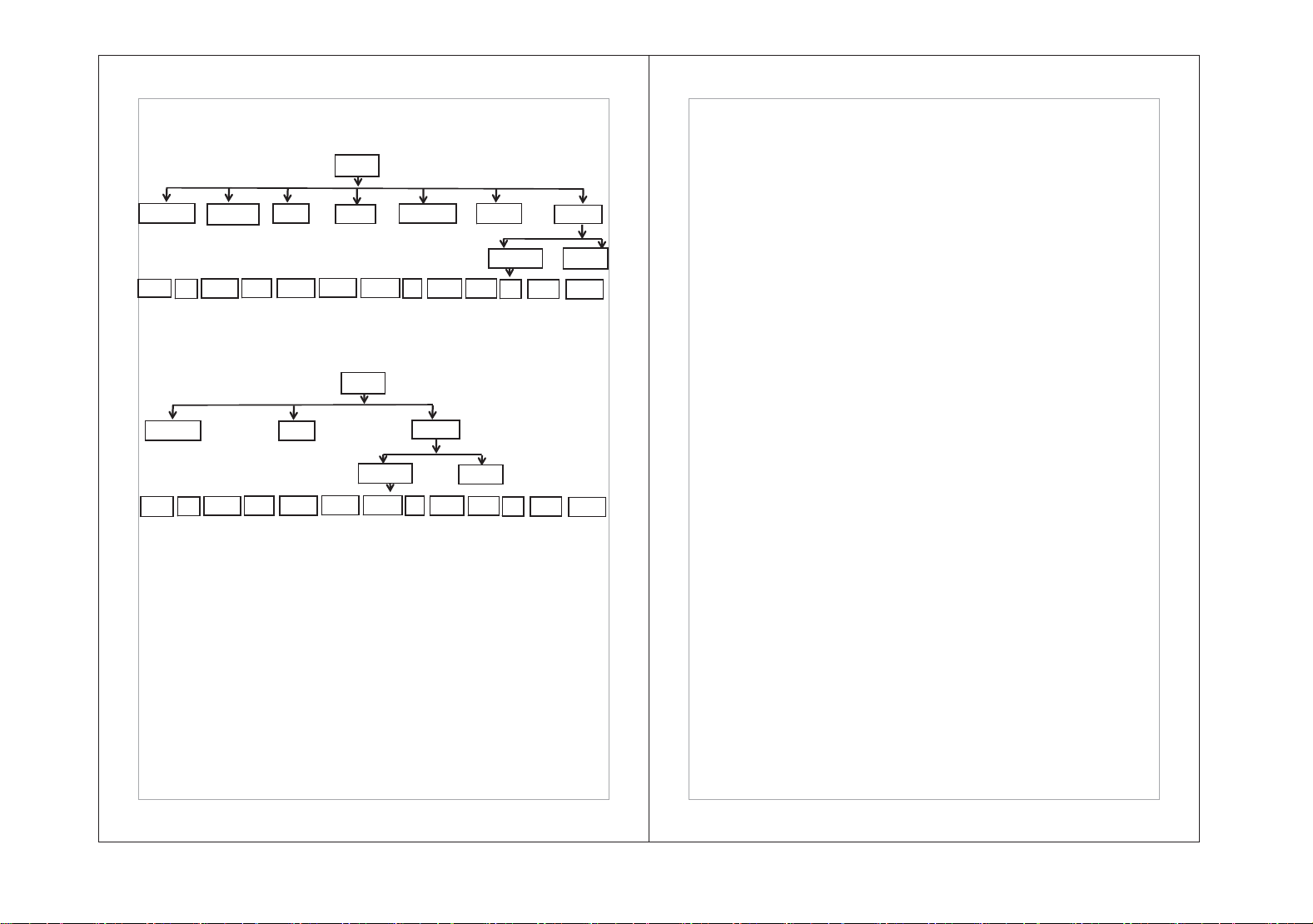
• Keypad
•
Users can scroll through the function menu by pressing【<>】to select a
function, press【Ok】to confirm or press【 】to go back to the last menu.
•
Users can use the 4X3 alphanumeric keypad to input the contact aliases,
ID and text messaging. Many characters require that you press a key multiple
times. The table below shows the number of times a key needs to be pressed
to generate the required character.
,.?
ABC
GHI
JKL
TUV
MNO
PQRS
CAPS
WXYZ
DEL
DEF
Number of Times Key is Pressed
Key
1 2 3 4 5 6 7 8 9 10 11 12 13
1 . , ? !@&`% : * #
ABC2
DEF3
GHI4
JKL5
MNO6
PQRS7
TUV8
WXYZ9
Operation of MENU
Most functions can be realized through the menu. The steps of Menu operation
as below.
-Press【Ok】key to enter menu page, Press【<>】Key to chooseitems in Menu.
-Press【Ok】key to confirm a selection or entry next page.
-Press【 】key return to previous page.
Note: After a period of inactivity, the radio will automatically exit the menu and
return to standby.
Note: Press To Enter "O" And Long Press To Activate
The CAPS Lock Another Long Press To Turn Off
The CAPS Lock
Note: press during text entry to delete the character.
Press during numeric entry to enter a " * "
Note: press during text entry to insert a space.
Press during numeric entry to enter a " # "
0
* or der
# or space
-
98
Klein Electronics, Inc. 2026Klein Electronics, Inc. 2026
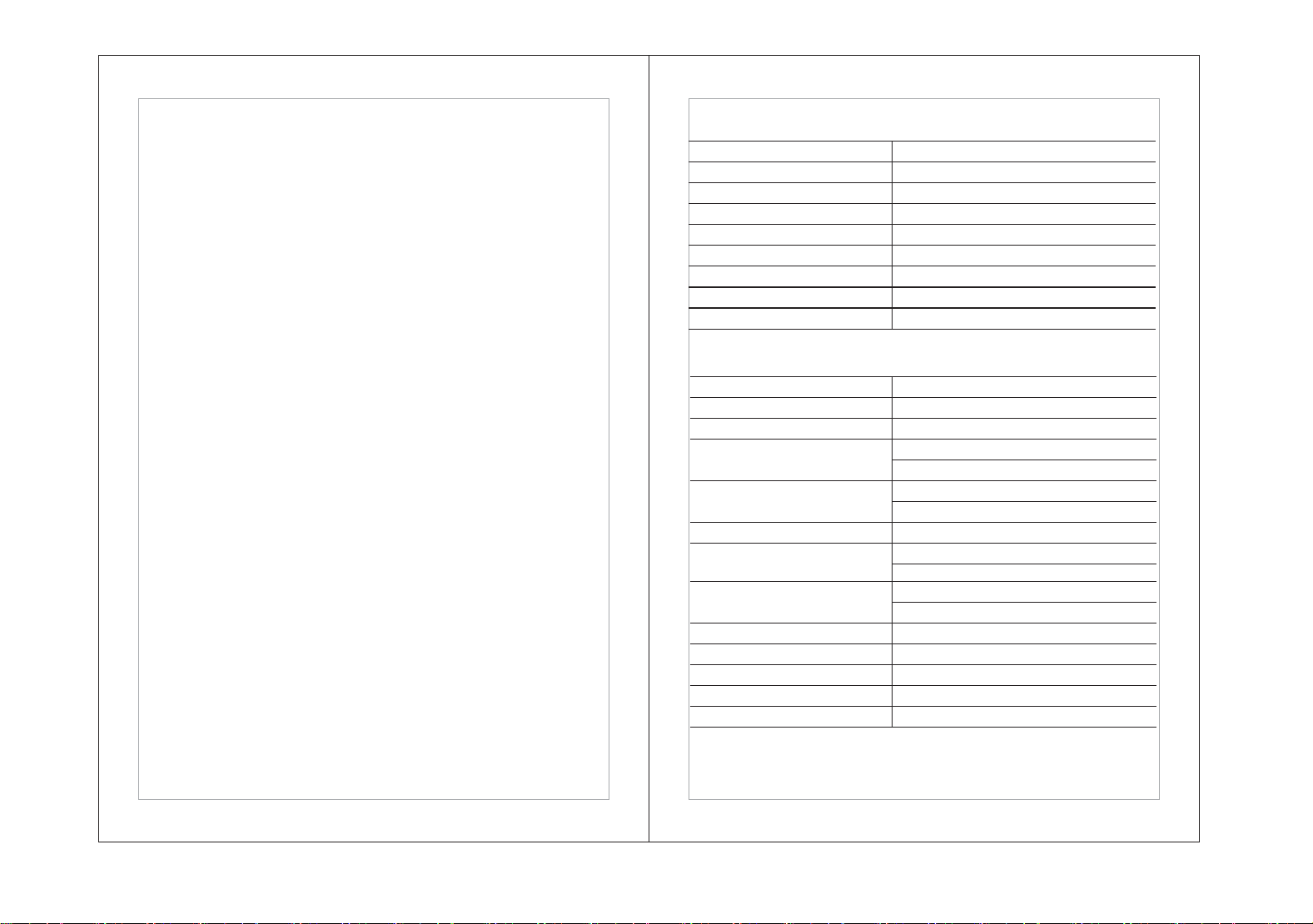
Menu
Bluetooth
Contacts Scan
Zone
Messa
g
es
CallLo
g
UƟůŝƟes
Radio Seƫng
Power
To ne s/ Al e rt s
Backlight Intro Screen
Keypad Lock
LED Indicator
VOX
Talkaround
Password
Clock
CH Mode
Radio Info
Talkaround
Man Down
Scan
Menu
Bluetooth
UƟůŝƟes
Radio Seƫng
Power
Tones/Alerts
Backlight Intro Screen
Keypad Lock
LED Indicator
VOX
Talkaround
Password
Clock CH Mode
Radio Info
Talkaround
Man Down
Menu of Digital Mode
Menu of Analog Mode
Under the menu, users can set up the corresponding functions but there are
some functions that can only be used on radio after they are set in the
programming software.
Transmitting and Receiving Communications
PTT Key
Tune the channel knob to select the desired channel.Press PTT to send the
signal, release the PTT to receive.
Select a Zone
A Zone is a channel zone. Each zone supports 16 channels. The radio can
support max 32 channel zones.
Press【Ok】key enter menu page, then press【<>】Key to access
menu and select the ‘Zone’, then press 【Ok】key to confirm. Turn the channel
knob to select a channel under this zone.
Receive and Respond to a call
When the LED is green, the radio is receiving. When the LED is red,the radio is
transmitting.
Receive and Respond to a Group Call
Your radio should be within the selected group. When your radio receives a group
call:
1. The LED will be green.
2. The first line of LCD will display the transmitting radio ID or alias. The second
line of LCD will show the alias of group call (only available on digital mode.)
3. Press PTT key to respond to the call. The LED will be red
4. Speak into the microphone.
5. Release the PTT to receive.
Receive and Respond to a Private call
A Private Call is a call from one radio to one other radio.
There are two types of private calls. The first is to check if the other radio is
available prior to call. The other type initiates the call immediately.When you
receive a private call:
1. LED will be green.
2. The first line of LCD will display the transmitting radio ID or alias. The second
line will show”Private Call”.
3. Press PTT to talk. lf the radio's “channel free indicator" function is active, when
you release the PTT key, you will hear a short tone. it means this channel is
free now.

11
10
Klein Electronics, Inc. 2026Klein Electronics, Inc. 2026
4.Press PTT key to reply to the call. LED will be red.
5. Wait for the talk permit tone (if activated) then talk into the microphone.
6. Release PTT key to receive.
7. If no signal is received during set time, the call will end.
8. You will hear a short warning, and the LCD will show that the call is over.
Receive an All Call.
All Call is one radio calling all radios on one channel
When you receive the All Call:
1.LED will be green.
2.The first line of LCD will display the transmitting radio ID or alias.The second
line will show the All-Call ID(16777215) or alias.
3.When the All Callis over, radio will return to standby. lf the “channel free
indictor" function is active, when the other radio's PTT is released, you will hear
a short tone. lt means this channel is now free.
4.You cannot reply to an All Call.
Note: When you receive an All-Call, if you turn to another channel, the radio will
stop receiving the All Call. During the All Call, the pre-programmed function keys
are disabled, until the All Call has ended.
Making a Radio Call
Select a channel, subscriber alias or ID, or group alias or ID by using.
• The Channel Selector Knob
• A programmed One Touch Access button
• The Contacts list
• Manually dial (by contact lists)
Note: lf the “Privacy" function is not active, the radio can't send the encryption
codes. Only radios with the same encryption codes are able to unscramble the
transmissions to each other.
Making a Call with the Channel Selector Knob
Making a Group Call
To make a call to a group of users, your radio must be configured aspart of that
group.
Procedure below:
1.Select the channel with the active group call alias or ID.
2.Hold the radio vertically 1 to 2 inches (2.5 to 5.0cm) from you rmouth.
3.Press the PTT button to make the call. The LED lights up solid red. The LCD
displays the group alias or ID.
4.Wait for the Talk Pemit Tone to finish (if enabled) and speak clearly into the
microphone.
5.Release the PTT button to listen, and when the target radio responds, the LED
blinks green.
On the radio you will see the group alias or ID and transmitting radio aliasor
ID on your display.
6.If the Channel Free Indication feature is enabled, you will hear ashort tone
when the target radio releases the PTT button,indicating that the channel is
free for you to respond. Press the PTT button to respond or if there is no
activity for the preset period, the call will end.
7.Radio returns to the screen you were on prior to the call initiating. You can
also make a Group Call using the Contacts list.
Making an All Call
The All-Call feature allows you to transmit to all users on a channel.
Your radio must be programmed to allow this feature.
1.Use the channel knob to select the channel with the active All Call alias or ID
(16777215).
2. Hold the radio vertically 1 to 2 inches (2.5 to 5.0 cm) from your mouth.
3. Press the PTT button to make the call. The LED lights up solid red.The LCD
displays the All-Call alias or ID (16777215).
4. Wait for the Talk Pemit Tone to finish (if enabled) and speak clearly into the
microphone.
Note: Users on the channel cannot respond to an All Call.
Making a Group Call or Private Call with the One Touch Access Button
The One Touch Access feature allows you to make a Group or Private Call to a
predefined alias or ID easily. This feature can be assigned to a short or long
press on a programmable side button, or to a long numeric button press on radio.
You can ONLY have one alias or ID assigned to a One Touch Access button
press. Your radio can have up to six One Touch Access buttons programmed.
1.Press the programmed One Touch Access button to make a Group or Private
Call to the predefined alias or ID.
13
12
Klein Electronics, Inc. 2026Klein Electronics, Inc. 2026
2.Hold the radio vertically 1 to 2 inches (2.5 to 5.0 cm) from your mouth.
3.Press the PTT button to make the call. The LED lights up solid red. The caller
alias appears in the display.
4.Wait for the Talk Permit Tone to finish (if enabled) and speak clearly into the
microphone.
5.Release the PTT button to listen. When the target radio responds, the LED
blinks green.
6.If the Channel Free Indication feature is enabled, you hear a short alert tone
when the target radio releases the PTT button, indicating the channel is free
for you to respond. Press the PTT button to respond.Or if there is no voice
activity for a predetermined period, the call ends.
7.Radio returns to the screen you were on prior to initiating the call.
Note: On a Private Call,you will hear a short tone when the call ends.
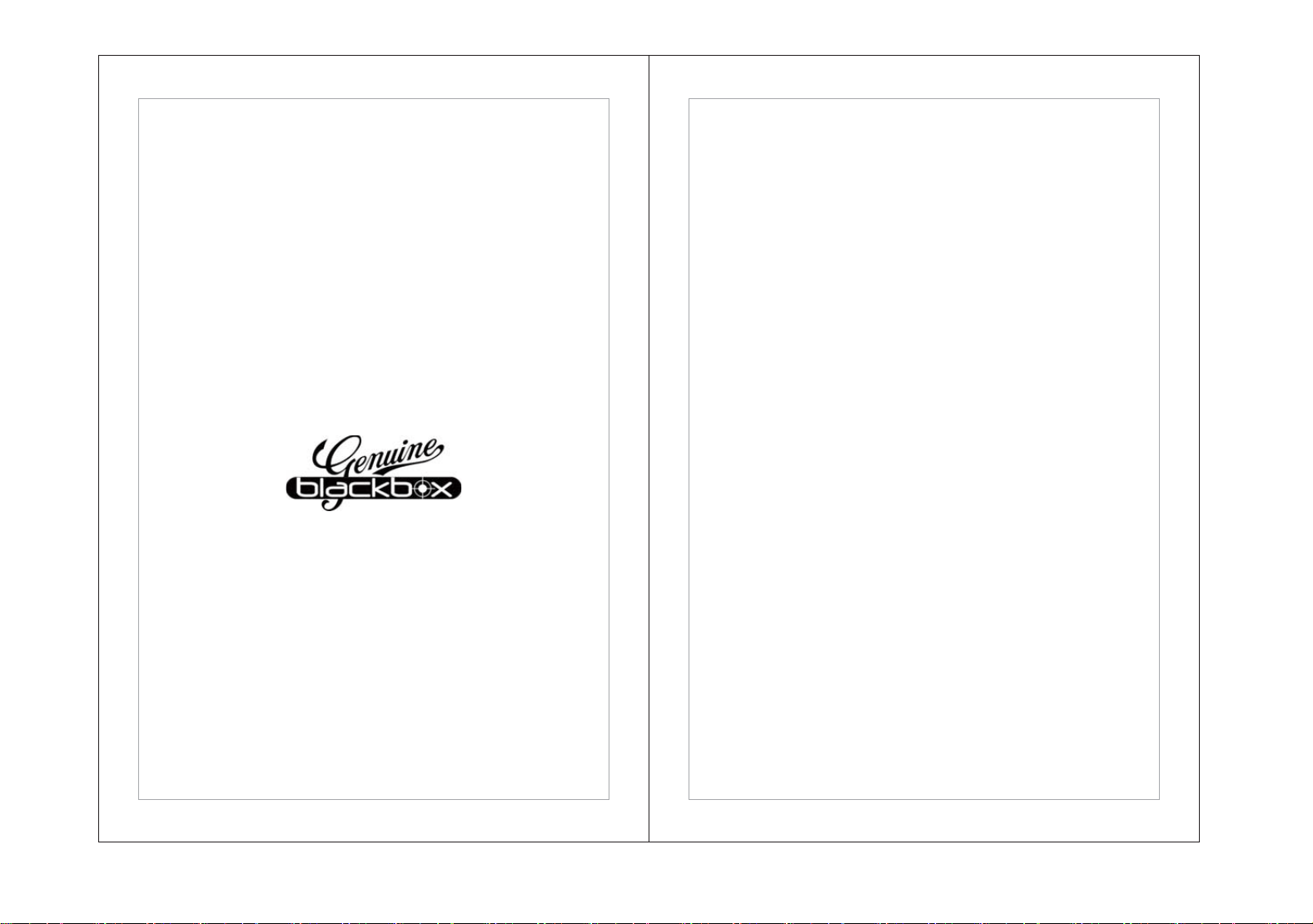
SPECIFICATIONS: Bluetooth v4.0. Low-Energy frequency: 2.4Ghz
Frequency Range
Channel Capacity
Operating Voltage
Operating temperature
Store temperature
Weight
Dimension: Hx Wx D(mm)
Dust-protection and water resistant
Battery Life (95% standby /5% active)
Frequency Range
Channel Spacing
Frequency Stability
Analog Sensitivity
Digital Sensitivity
Intermodulation
Adjacent Channel Selectivity
Spurious Response rejection
Co-Channel rejection
Blocking
Rated Audio Output Power
Audio response
Rated Audio Distortion
400-470MHz
12.5kHz
+/-1.0ppm
0.28uV/-116dBm (20dB SINAD)
0.22uV/-120dBm (Type)
0.28uV/-117.4dBm (BER5%)
0.5uV/-110dBm (BER1%)
TIA603C: 65dB ETSI:60dB
TIA603C: [email protected]
ETSI:>[email protected]
65dB(TIA603D)
65dB(ETSI)
>84dB (ETSI)
1W
+1~-3dB
3%(Type)
400-470MHz
512
7.4V
-25°C~+60°C
40°C~+85°C
9.5 oz with standard Li-ion battery
137x54x33.5 with standard Li-ion battery
IP56
Digital: 18hrs (2000 mAh Standard Li-ion battery)
RECEIVER

15
14
Klein Electronics, Inc. 2026Klein Electronics, Inc. 2026
Frequency Range
Channel Spacing
Frequency Stability
Power
Hum and Noise
Conducted/Radiated emission
Adjacent Channel Power
FM Modulation
4FSK digital modulation
Modulation Maximum Deviation
Nonactive Slot Power
Audio Response
Digital Protocol
Vocoder Type
TRANSMITTER
400-470MHz
12.5kHz
+/-1.0ppm
Low Power: 1.2W, High Power: 5W
G%P*+]G%P!*+]
.+].2)(
12.5KHz data only: 7K60FXD
12.5KHz voice and data: 7K60FXE
.+]#.+]
57dBm
+1dB~-3dB
ETSITS 102 361-1,-2,-3
AMBE+2TM
FCC:
Any changes or modifications not expressly approved by the party responsible for
compliance could void the user's authority to operate the equipment.
This device complies with part 15 of the FCC Rules. Operation is subject to the following
two conditions: (1) This device may not cause harmful interference, and (2) this device
must accept any interference received,including interference that may cause undesired
operation.
Note: This equipment has been tested and found to comply with the limits for a Class B
digital device, pursuant to part 15 of the FCC Rules. These limits are designed to provide
reasonable protection against harmful interference in a residential installation. This
equipment generates, uses and can radiate radio frequency energy and, if not installed
and used in accordance with the instructions, may cause harmful interference in radio
communications. However, there is no guarantee that interference will not occur in a
particular situation. lf this equipment does cause harmful interference to radio or
television reception, which can be determined by turning the equipment off and on, the
user is encouraged to try to correct the interference by one or more of the following
measures:
- Reorient or relocate the receiving antenna.
- Increase the separation between the equipment and receiver.
- Connect the equipment into an outlet on a circuit different from that to which the
receiver is connected.
- Consult the dealer or an experienced radio/TV technician for help.
This radio is designed for and classified as “Occupational/Controlled Use Only", meaning
it must be used only during employment by individuals aware of the hazards, and the
ZD\VWRPLQLPL]HVXFKKD]DUGV1RWLQWHQGHGIRUXVHLQWKH*HQHUDOSRSXODWLRQ
uncontrolled environment.
DO NOT operate the radio without a proper antenna attached, as this may damage the
radio and may also cause you to exceed RF exposure limits. A proper antenna is the
antenna supplied with this radio by the manufacturer or an antenna specifically
authorized by the manufacturer for use with this radio.
DO NOT transmit for more than 50% of total radio use time, more than 50%of the time
can cause RF exposure compliance requirements to be exceeded. This transmitter may
operate with the antenna(s) documented in this filing inPush-to-Talk and body-worn
configurations. RF exposure compliance is limited to the specific belt-clip and accessory
configurations as documented in this filing and the separation distance between user and
the device or its antenna shall be at least 2.5 cm.
This device complies with part 15 of the FCC Rules. Operation is subject to the
condition that this device does not cause harmful interference.
WARNING:
MODIFICATION OF THIS DEVICE TO RECEIVE CELLULAR RADIOTELEPHONE
SERVICE SIGNALS IS PROHIBITED UNDER FCC RULES AND FEDERAL LAW.
15
Klein Electronics, Inc. 2026
CONTACT your salesperson for technical support!
Blackbox and GO-KP are Trademarks of Klein Electronics, Inc. 2026
ISED Statement
Déclaration d'ISDE
This device contains licence-exempt transmitter(s)/receiver(s) that comply with
Innovation, Science and Economic Development Canada’s licence-exempt RSS(s).
Operation is subject to the following two conditions:
(1) This device may not cause interference.
(2) This device must accept any interference, including interference that may cause
undesired operation of the device.
L’émetteur/récepteur exempt de licence contenu dans le présent appareil est
conforme aux CNR d’Innovation, Sciences et Développement économique Canada
applicables aux appareils radio exempts de licence. L’exploitation est autorisée
aux deux conditions suivantes:
(1) L' appareil ne doit pas produire de brouillage;
(2) L' appareil doit accepter tout brouillage radioélectrique subi, même si le
brouillage est susceptible d' en compromettre le fonctionnement.
This EUT is compliance with SAR for controlled exposure limits in ISED RSS-102
at operating duty cycle of up to 50% and had been tested in accordance with the
measurement methods and procedures specified in IEC/IEEE 62209-1528. This
equipment should be installed and operated with a minimum distance of 2.5 cm
must be maintained when held-to-face, and body-worn operations are restricted to
the approved original accessories (belt clip), a minimum distance of 0 cm.
Cet EUT est conforme aux limites d'exposition contrôlées SAR de la norme ISDE
RSS-102 pour un cycle de service de fonctionnement allant jusqu'à 50 % et a été
testé conformément aux méthodes et procédures de mesure spécifiées dans la
norme IEC/IEEE 62209-1528. Cet équipement doit être installé et utilisé à une
distance minimale de 2,5 cm lorsqu'il est tenu face au visage et les opérations
portées sur le corps sont limitées aux accessoires d'origine approuvés (clip de
ceinture), à une distance minimale de 0 cm.
This radio transmitter IC: 6388A-BGOKP has been approved by Innovation,
Science and Economic Development Canada to operate with the antenna types list
ed below, with the maximum permissible gain indicated. Antenna types not included
in this list that have a gain greater than the maximum gain indicated for any type
listed are strictly prohibited for use with this device.
Cet émetteur radio IC: 6388A-BGOKP a été approuvé par Innovation, Sciences
et Développement économique Canada pour fonctionner avec les types d'antenne é
numérés ci-dessous, avec le gain maximal admissible indiqué. Les types d'antenne
non inclus dans cette liste qui ont un gain supérieur au gain maximum indiqué pour
tout type répertorié sont strictement interdits pour une utilisation avec cet appareil.
Antenna Type: Detachable Antenna
Antenna Gain: 2.15dBi
Frequency Range: 400-470MHz