
OWNER'S MANUAL
Use this owner's manual to reference installation,
troubleshooting and lter replacement information.
If you need help or have a question,
we've got you covered.
Give us a call at 833.232.9711
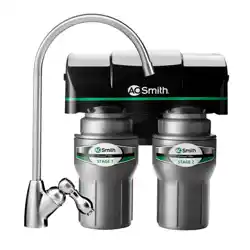
AOW-2000
2-STAGE UNDER SINK
Sistema bajo el fregadero de 2 etapas
A. O. Smith Corporation P.O. Box 1597 | Johnson City, TN 37605-1597 | 833.232.9711
Owner’s Manual / El manual del proprietario
NEED HELP? GIVE US A CALL 833.232.9711
NEED HELP? GIVE US A CALL 833.232.9711
AOW-2000
2-STAGE UNDER SINK
TABLE OF CONTENTS
Box Contents ............................................................................................................1
Installation Guide ................................................................................................. 2-3
Care and Maintenance .............................................................................................4
Performance Data Sheet ..........................................................................................5
Warranty ...................................................................................................................6
Spanish/Español ........................................................................................................7
A. O. Smith has designed, engineered, and built this ltration system to last. It
features Claryum
®
ltration that reduces harmful contaminants – those you can
see, smell and taste, and those you can’t – with no chemical additives or wasted
water. Whatever your water need – from hydration to cooking, early
morning coffee, smoothies, or soup, you will now have ltered water.
Keep this owner’s manual to reference installation, troubleshooting
and lter replacement information.
If you need help or have a question, we’ve got you covered.
Give us a call at 833.232.9711.
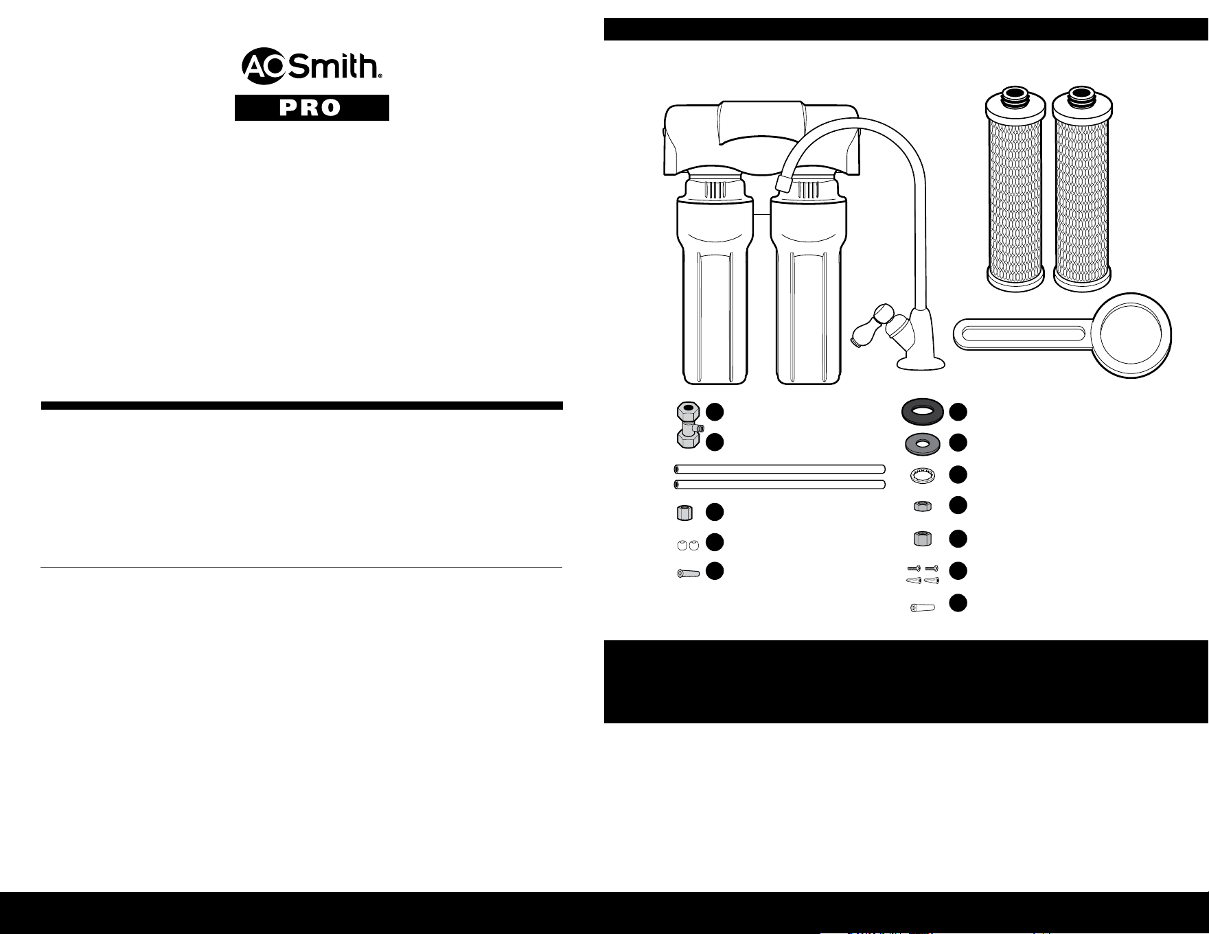
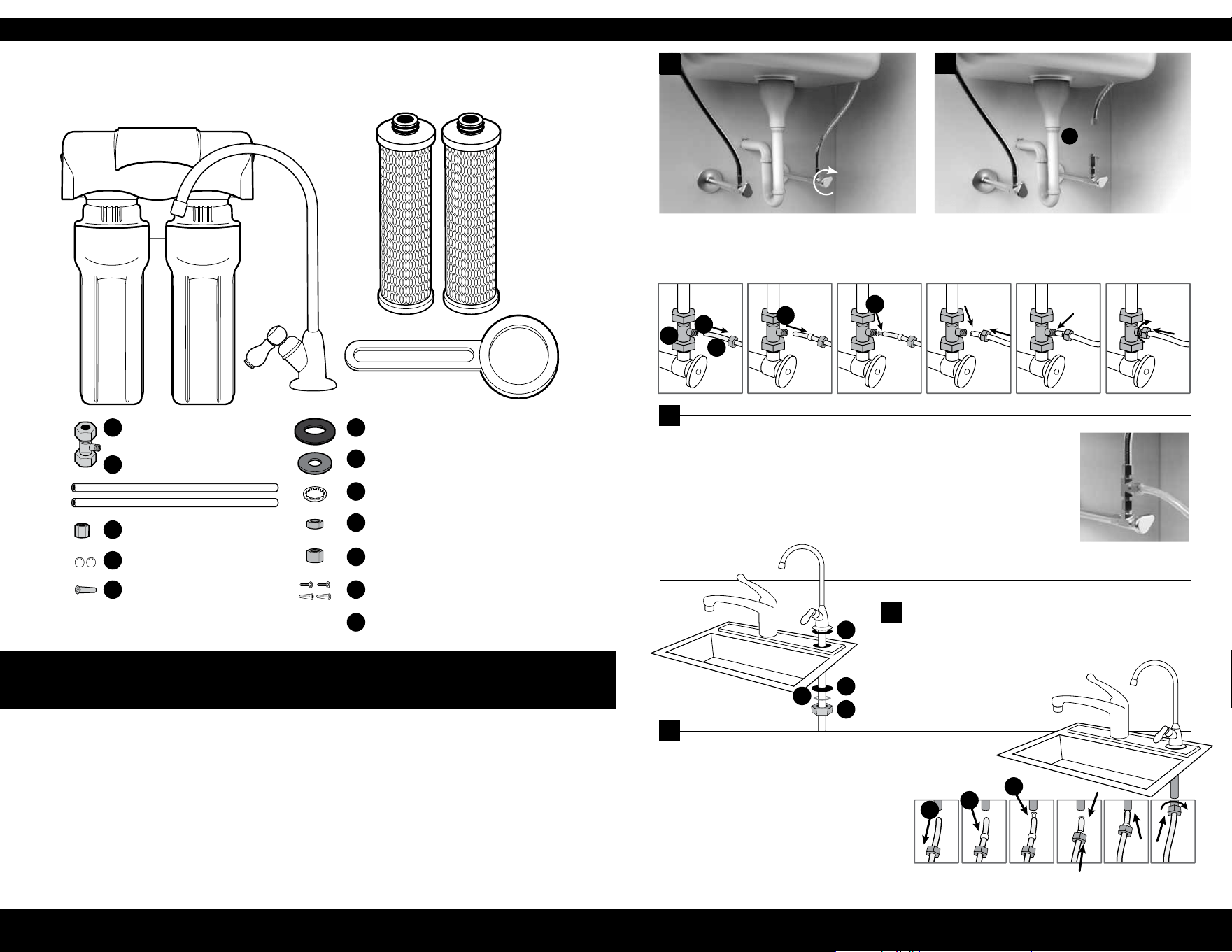
BOX CONTENTS
1
Tools recommended for installation:
• Variable speed drill w/ 7/32" bit
• Adjustable wrench
• Measuring tape
• Bucket
• Phillips head screwdriver
• Hammer
Faucet may be mounted on sink using an
existing hole for a sprayer nozzle or soap
dispenser, or by drilling a hole no more
than 1/2" in diameter. Be sure location
of faucet allows spout to extend slightly
past the edge of sink.
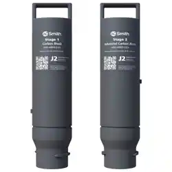
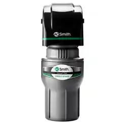
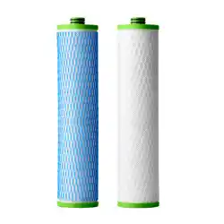
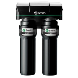
AOW-2000 FILTER UNIT FAUCET FILTER CARTRIDGES (2)
FAUCET RUBBER WASHER
FAUCET SPACER
FAUCET WASHER
FAUCET NUT
CHROME NUT
SCREWS WITH ANCHORS (2)
PLASTIC TUBE INSERT
Note: We recommend using an approved or certied professional if drilling is required.
1/4" BRASS TEE
3’ X 1/4" POLY TUBING (2)
BRASS NUT
PLASTIC COLLAR (2)
BRASS TUBE INSERT
WRENCH
Please read entire manual to ensure all parts listed are present before installation.
If any part is missing or damaged let us know by calling 833.232.9711.
Do not attempt to install the lter.
A
B
C
D
E
H
F
G
I
J
K
L
NEED HELP? GIVE US A CALL 833.232.9711
NEED HELP? GIVE US A CALL 833.232.9711
9
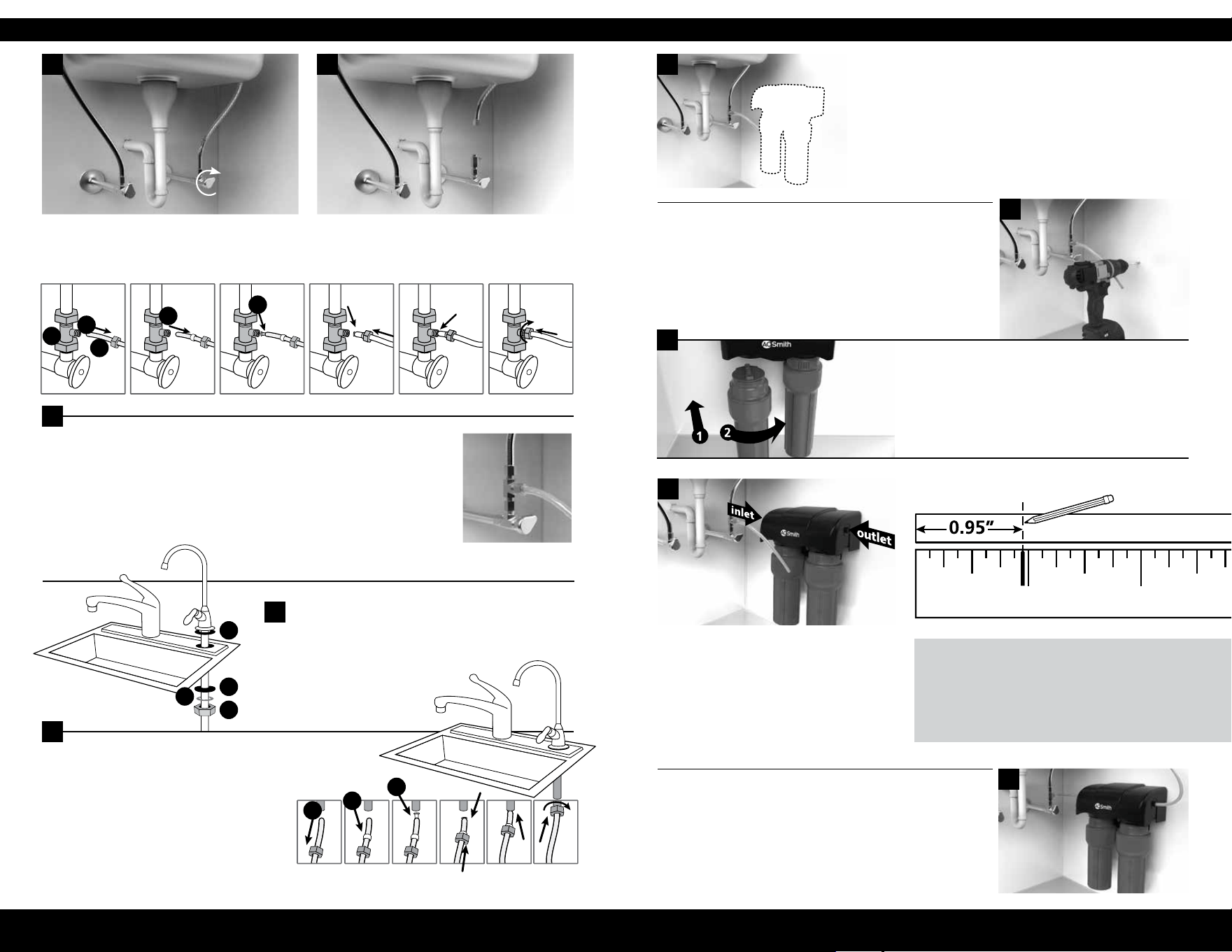
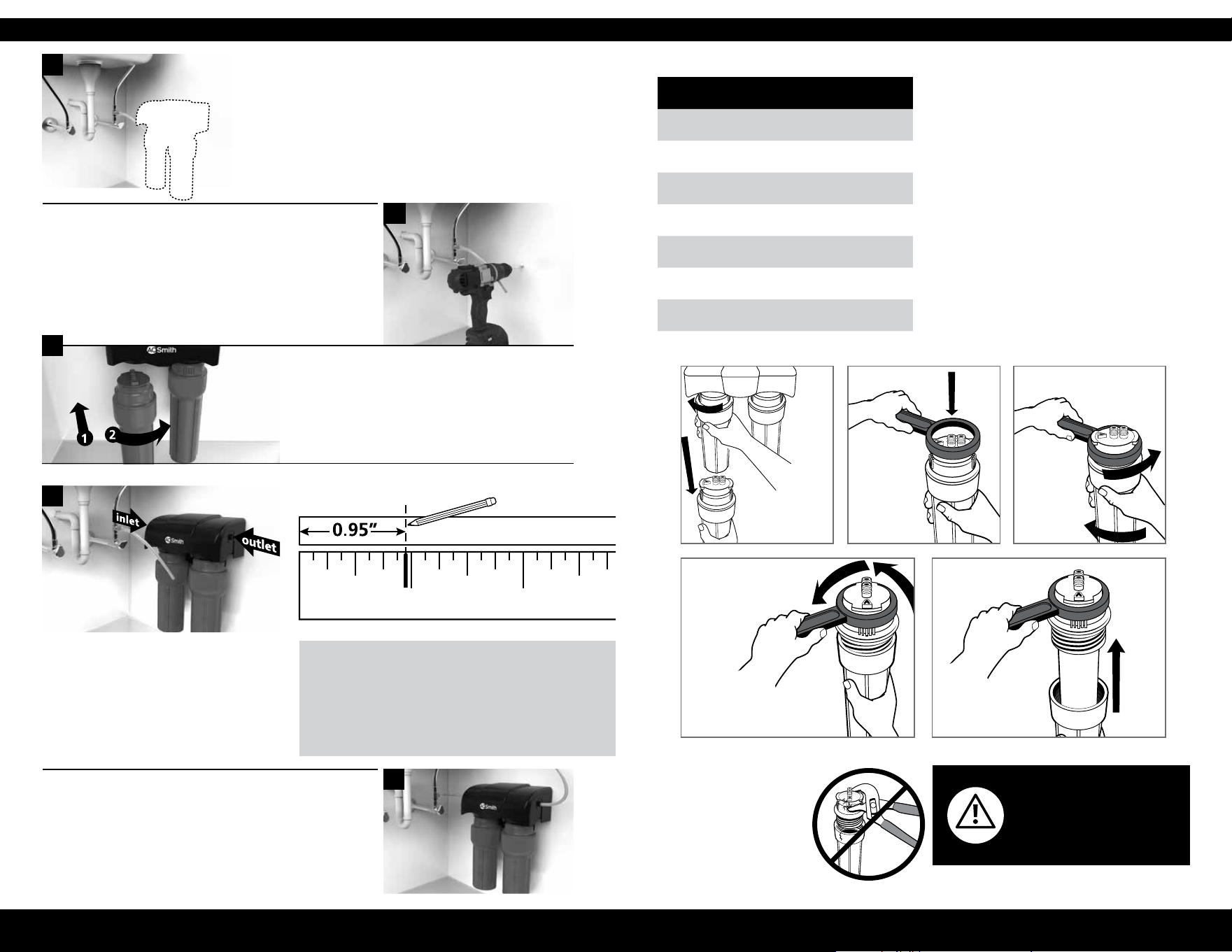
Check for leaks and proper installation: Turn on
cold water. Place towel under lter unit and check
for leaks. Allow water to run 10 minutes to ush.
Note: Never use oils to lubricate the O-rings;
O-rings come pre-lubricated.
Unit installation: Select a space under sink for lter
unit that is at least 3" from bottom of your cabinet
and allows for easy access to cold water supply and
lter replacements. Use mounting holes located on
back of unit to pencil in the wall screw placements.
Note: Center to center hole distance is 2.55".
Use a 7/32" drill bit to drill holes for plastic anchors.
Carefully tap anchors into the drilled hole with a
hammer. Mount unit to the wall with screws. Pull
protective plastic strip from the battery compartment.
The red LED should ash and beep ve (5) times to
indicate that battery is installed correctly.
Faucet connection: Connect outlet hose
to base of faucet by sliding chrome nut
onto tube followed by the white collar.
Place white insert into the end
of tube. Press tube against the faucet
base and slide the nut and collar up to
the threads. Use wrench to ensure seal
is sufciently tight.
INSTALLATION GUIDE
Connect supply lines: Insert tubing from
tee tting into the inlet side and insert
tubing from faucet into the outlet side.
Use diagram to mark tubing depth to
ensure they are completely inserted.
It is VERY IMPORTANT to insert tubing
completely so leaking does not occur.
Faucet Installation: Install as shown.
Tighten faucet nut (I) to secure
faucet to sink.
TIPS
Insert tubing all the way (.95") to prevent leaking.
Wet end of tubing for an easy install into inlets and outlets.
Cut excess tubing to prevent crimping, kinks, loops or folds.
2
3
A
Attach one white poly tube to the brass tee, and slide compression
nut onto the tubing (with threads of nut facing end of the tube).
Next, slide the plastic sleeve onto the tube. Place brass insert into
the opening of tube. Push tip of the tube into opening of the brass
tee. While holding the tube in place inside the brass tee, tighten
compression nut to compress plastic sleeve and create a seal.
1 2
3
Depth to insert 2 stage tubing
Diagram is actual size.
Note: Avoid over-tightening.
Note: Avoid over-tightening.
Turn off and disconnect cold water supply. Attach threaded ends of supplied brass
tee to cold water supply line and shut-off
valve; tighten using an adjustable wrench.
A
B
C
D
E
H
F
G
I
1 2
3
5
J
D
L
4
6
7
10
Attach each sump to bottom of the unit
housing. Align connection points, push
sump up and turn to the right.
Note: Ensure the sump is locked in.
8
NEED HELP? GIVE US A CALL 833.232.9711
To clean your lter unit, wipe down
the exterior with a damp cloth.
Once lters are at 95% capacity (about
every 6 months), the battery alarm will
sound and ash red when water is
owing and will continue for 15 seconds
once water is turned off. Change the
battery every time you replace your lters.
The battery is included with the lter
replacement cartridges.
Safeguards
• Use only cold water with lter.
• If you experience a hose connection
leak, disconnect and re-seat the hose.
Do not use with water that is microbiologically
unsafe or of unknown water quality without
adequate disinfection before or after the
system. Systems certied for cyst reduction
may be used on disinfected waters that may
contain lterable cysts.
CARE AND MAINTENANCE
4
AOW-2000
Replacement cartridge AOW-2000-R
Rated service ow .5gpm (1.89 lpm)
Max capacity 500 gal (1892 liters)
Min working pressure 20 psi (137 kPa)
Max working pressure 80 psi (551 kPa)
Min operating temperature 40° F (4.44° C)
Max operating temperature 90° F (32.22° C)
CARE AND MAINTENANCE
5
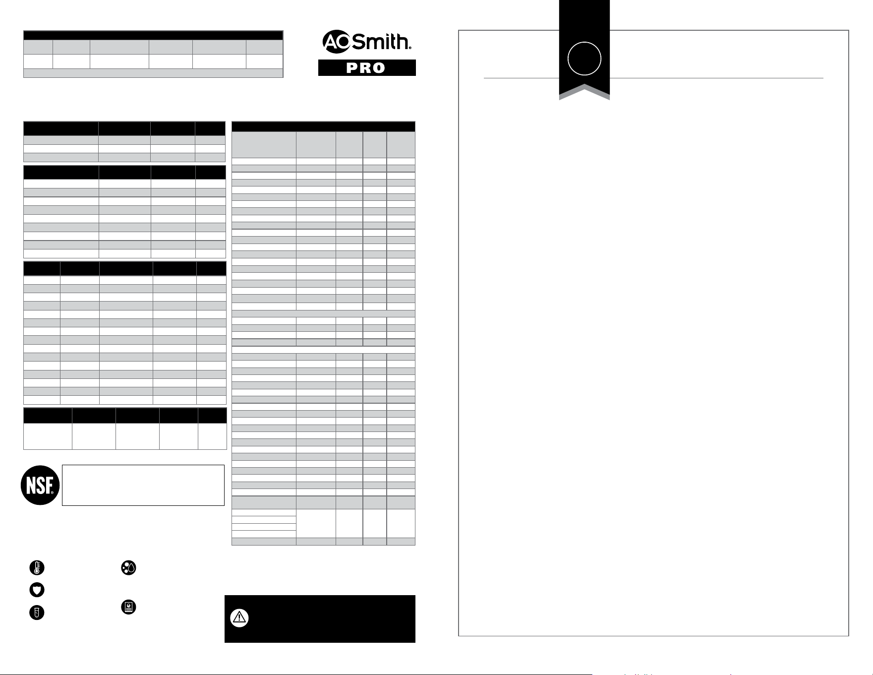
Performance Data Sheet for the A. O. Smith Under Counter Water Filter
Models Replacement Operating pressure range Rated capacity Operating temp. range Rated ow
AOW-2000
AOW-2000-R 20-80 psi
137-551 kPa
500 gallons
1892 Liters
40-90° F
4.44-32.2° C
.05 gpm
1.89 lpm
Manufactured by: A. O. Smith Corporation 11270 West Park Place | Milwaukee, WI 53224 | 833.232.9711
Organic chemicals included by surrogate testing
VOCs
(by surrogate testing
using chloroform)
Drinking
water
regulatory
level (MCL/
MAC) mg/L
Inuent/
Unltered
Efuent/
Filtered
Percent
Reduction
alachlor 0.002 0.050 0.001 >98%
atrazine 0.003 0.100 0.003 >97%
benzene 0.005 0.081 0.001 >99%
carbofuran 0.04 0.190 0.001 >99%
carbon tetrachloride 0.005 0.078 0.0018 98%
chlorobenzene 0.1 0.077 0.001 >99%
chloropicrin — 0.015 0.0002 99%
2,4-D 0.07 0.110 0.0017 98%
dibromochloropropane (DBCP) 0.0002 0.052 0.00002 >99%
o-dichlorobenzene 0.6 0.080 0.001 >99%
p-dichlorobenzene 0.075 0.040 0.001 >98%
1,2-dichloroethane 0.005 0.088 0.0048 95%
1,1-dichloroethylene 0.007 0.083 0.001 >99%
cis-1,2-dichloroethylene 0.07 0.170 0.0005 >99%
trans-1,2-dichloroethylene 0.1 0.086 0.001 >99%
1,2-dichloropropane 0.005 0.080 0.001 >99%
cis-1,3-dichloropropylene — 0.079 0.001 >99%
dinoseb 0.007 0.170 0.0002 99%
endrin 0.002 0.053 0.00059 99%
ethylbenzene 0.7 0.088 0.001 >99%
ethylene dibromide (EDB) 0.00005 0.044 0.00002 >99%
haloacetonitriles (HAN)
bromochloroacetontrile — 0.022 0.0005 98%
dibromoacetontrile — 0.024 0.0006 98%
dichloroacetontrile — 0.0096 0.0002 98%
trichloroacetontrile — 0.015 0.0003 98%
haloketones (HK)
1,1-dichloro-2-propanone — 0.0072 0.0001 99%
1,1,1-trichloro-2-propanone — 0.0082 0.0003 96%
heptachlor (H-34, Heptox) 0.0004 0.025 0.00001 >99%
heptachlor epoxide 0.0002 0.0107 0.0002 98%
hexachlorobutadiene — 0.044 0.001 >98%
hexachlorocyclopentadiene 0.05 0.060 0.000002 >99%
lindane 0.0002 0.055 0.00001 >99%
methoxychlor 0.04 0.050 0.0001 >99%
pentachlorophenol 0.001 0.096 0.001 >99%
simazine 0.004 0.120 0.004 >97%
styrene 0.1 0.150 0.0005 >99%
1,1,2,2-tetrachloroethane — 0.081 0.001 >99%
tetrachloroethylene 0.005 0.081 0.001 >99%
toluene 1 0.078 0.001 >99%
2,4,5-TP (silvex) 0.05 0.270 0.0016 99%
tribromoacetic acid — 0.042 0.001 >98%
1,2,4-trichlorobenzene 0.07 0.160 0.0005 >99%
1,1,1-trichloroethane 0.2 0.084 0.0046 95%
1,1,2-trichloroethane 0.005 0.150 0.0005 >99%
trichloroethylene 0.005 0.180 0.0010 >99%
trihalomethanes (THMs)
Inuent/
Unltered
Efuent/
Filtered
Percent
Reduction
bromodichloromethane (THM)
0.080 0.300 0.015 95%
bromoform (THM)
chloroform (THM)
chlorodibromomethane (THM)
xylenes (total) 10 0.070 0.001 >99%
NSF/ANSI 42 Min Reduction Overall % Reduction Results
Chlorine Reduction, Free Available
<0.5 mg/l 97.66% Pass
Chloramine Reduction, Free Available
<0.5 mg/l 97.66% Pass
Particulate Reduction 85% 99.9% Pass
NSF/ANSI 53 Min Reduction Overall % Reduction Results
Cyst Live Cryptosporidium & Giardia 99.95% >99.99% Pass
Mercury Reduction pH 8.5 <2 ug/L >95% Pass
Mercury Reduction pH 6.5 <2 ug/L >96.5% Pass
Lead Reduction pH 6.5 <10 ug/L >99.4% Pass
Lead Reduction pH 8.5 <10 ug/L >99.3% Pass
MTBE Reduction <5 ug/L 86.6% Pass
Turbidity <0.5 NTU 99.1% Pass
VOC Surrogate Test 95% 99.4% Pass
Asbestos 99% >99% Pass
NSF/ANSI 401
Maximum
Concentration
Minimum Reduction Overall % Reduction Results
Atenolol 30 ng/L 94.2% 94.2% Pass
Bisphenol A 300 ng/L 98.80% 98.9% Pass
Carbamazepine 200 ng/L 98.6% 98.6% Pass
DEET 200 ng/L 98.7% 98.7% Pass
Estrone 20 ng/L 96.30% 96.5% Pass
Ibuprofen 60 ng/L 95.3% 95.4% Pass
Linuron 20 ng/L 96.6% 96.6% Pass
Meprobamate 60 ng/L 94.7% 94.7% Pass
Metolachlor 200 ng/L 98.6% 98.6% Pass
Naproxen 20 ng/L 96.3% 96.4% Pass
Nonyl phenol 200 ng/L 97.50% 97.5% Pass
Phenytoin 30 ng/L 95.50% 95.6% Pass
TCEP 700 ng/L 98% 98% Pass
TCPP 700 ng/L 97.8% 97.8% Pass
Trimethoprim 20 ng/L 96.7% 96.7% Pass
NSF P473
Inuent challenge
concentration
Maximum
permissible
concentration
Overall % reduction Results
Peruorooctanoic
acid (PFOA) &
Peruorooctane
sulfonate (PFOS)
1.5 ±10% ug/L 0.07 ug/L 96 % Pass
System Tested and Certied by NSF International against NSF/
ANSI Standard 42, 53 & 401 and conforms to NSF protocol
P473 for reduction of claims specied on the Performance
Data Sheet and at www.nsf.org.
For use with municipally treated water only. Do not use with
water that is microbiologically unsafe or of unknown water
quality without adequate disinfection before or after the system.
Filter is only to be used
with cold water.
Filter usage must comply
with all state and local laws.
Testing was performed
under standard laboratory
conditions, actual
performance may vary.
Systems certied for cyst
reduction may be used on
disinfected waters that may
contain lterable cysts.
See owner’s manual for general
installation conditions and
needs plus manufacturer’s
limited warranty.
• All contaminants reduced by this lter are listed.
• Not all contaminants listed may be present in your water.
• Does not remove all contaminants that may be present in tap water.
Testing Performed under NSF/ANSI Standards 42 and 53 and in accordance with the California Department of Health Services Drinking Water Treatment
Device Program. This system has been tested according to NSF/ANSI 42, 53, 401 & P473 for reduction of the substances listed below. The concentration
of the indicated substances in water entering the system was reduced to a concentration less than or equal to the permissible limit for water leaving the
system, as specied in NSF/ANSI 42, 53, 401 & P473.
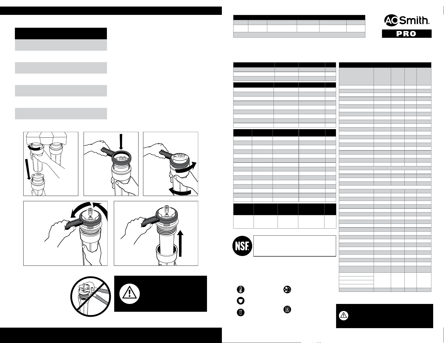
Remove
each sump
from the
manifold
by hand.
Place wrench
over sump
top and
slide down.
Continue turning
counterclockwise.
Remove top
and lter.
WARNING Do not use tools
to remove or tighten sumps.
Over-tightening can cause
damage and result in leaking.
HAND TIGHTEN ONLY.
Turn wrench
to right;
sump to
left.
LIMITED WARRANTY
6
What is covered:
This warranty covers defects in materials
or workmanship in manufacturing of
your A. O. Smith drinking water lter
systems, except as provided below.
For how long:
This warranty runs for 365 days from
the date of purchase by a consumer
(“Warranty Period”).
What is not covered:
This warranty does not cover lter
cartridges and any products that were
not installed in compliance with the
instructions or that have been abused
or operated incorrectly. The limited
warranty stated herein is in lieu of any
and all warranties, express or implied,
whether written or oral, including but
not limited to the implied warranties of
tness for a particular purpose or the
implied warranty of merchantability.
A. O. Smith shall not be liable for any
incidental, consequential, special or
contingent damages arising directly
or indirectly from any defect or the
use of the system. Owner shall be
responsible for all labor and any other
expenses related to the removal, repair
or installation of the ltration system
or any component part. Finally, this
warranty is voided if the product is
used with parts that are not genuine
A. O. Smith parts. This includes, but
is not limited to: replacement lters,
faucets, and diverter valves.
What A. O. Smith will do:
We will replace the defective part of
the covered product and send it to you
upon payment of $9.50 for shipping and
handling per incident.
How to get service:
To receive service under this
warranty, you must contact
A. O. Smith at 833-232-9711 or
within the Warranty Period and describe
the problem to a customer service
representative who will verify that the
product is under warranty and arrange
for delivery of a replacement part.
How state law applies:
This warranty gives you specic rights
but you may have other rights which
vary from state to state.
Some states do not allow the exclusion
or limitation of implied warranties or
incidental or consequential damages,
so the above limitation or exclusion
may not apply to you.
A. O. Smith Corporation P.O. Box 1597 | Johnson City, TN 37605-1597 | 833.232.9711
1
YEAR
AOW-2000
SISTEMA BAJO EL FREGADERO
DE 2 ETAPAS
TABLE DE CONTENIDO
Contenido de la caja ................................................................................................8
Guía de instalación ............................................................................................. 9-10
Cuidado y mantenimiento .....................................................................................11
Hoja de datos de rendimiento ..............................................................................12
Garantía ..................................................................................................................13
A.O. Smith diseñó, creó y construyó este sistema de ltración para durar. Cuenta
con la ltración Claryum
®
que disminuye los contaminantes dañinos, aquellos
que puede y no puede ver, oler y sentir su sabor, sin usar aditivos químicos o
aguas residuales. Sin importar para qué necesite el agua, para hidratarse, cocinar,
para el café de la mañana, los batidos o una sopa, ahora tendrá agua ltrada.
Conserve este manual del propietario como referencia para la instalación,
resolución de problemas e información de cambio del ltro.
7
1 2
• Taladro de varias velocidades con una
broca de 7/32”
• Llave ajustable
• Cinta métrica
• Cubeta
• Destornillador Phillips
• Martillo
La llave se puede montar en el fregadaro
en un oricio existente para una boquilla
pulverizadora o un dispensador de jabón
o puede perforar un oricio de no más de
1.3cm (1/2”) de diámetro. Asegúrese de
que la ubicación de la llave permita que el
conducto se extienda levemente más allá del
borde del fregadaro.
Nota: Recomendamos llamar a un profesional autorizado o certicado si es que se necesita perforar.
Lea todo el manual antes de la instalación para asegurarse
de que todas las piezas indicadas estén presentes.
UNIDAD DE FILTRADO AOW-2000 LLAVE CARTUCHOS DE FILTRO (2)
ARANDELA DE GOMA DE LA LLAVE
SEPARADOR DE LA LLAVE
ARANDELA DE LA LLAVE
TUERCA DE LA LLAVE
TUERCA DE CROMO
TORNILLOS CON ANCLAJES (2)
INSERTO PLÁSTICO DE TUBO
T DE LATÓN DE 1/4"
TUBERÍAS DE POLIETILENO
DE 0.9M X 0.6CM
(3' X 1/4") (2)
TUERCA DE LATÓN
COLLARÍN PLÁSTICO
INSERTO DE TUBO DE LATÓN
LLAVE
A
B
C
D
E
H
F
G
I
J
K
L
Conexión de la llave: Deslice la tuerca de cromo
en el tubo y después el collarín blanco para
conectar la manguera de salida a la base de la
llave. Coloque el inserto blanco en el extremo
del tubo. Presione el tubo contra la base de la
llave y deslice la tuerca y el collarín hasta las
roscas. Use una llave para asegurarse de que el
sello está apretado lo suciente.
Instalación de la llave: Realice la instalación como se
muestra. Apriete la tuerca de la llave (I) para jar la
llave al fregadaro.
A
Conecte una tubería de polietileno a la T de latón: deslice la tuerca de compresión en
la tubería (con las roscas de la tubería orientadas hacia el extremo del tubo). Luego,
deslice el manguito en el tubo. Coloque el inserto de latón en la abertura del tubo.
Empuje la punta del tubo hacia la abertura de la T de latón. Mientras sostiene el tubo
en su lugar dentro de la T de latón, apriete la tuerca de compresión para comprimir
el manguito de plástico y crear un sello.
Nota: Evite apretar demasiado.
Nota: Evite apretar demasiado.
Apague y desconecte el suministro de agua fría. Conecte los extremos roscados de la T de latón
incluida a la tubería de suministro de agua fría y a la
válvula de cierre. Apriete con una llave ajustable.
A
B
C
D
E
H
F
G
I
1
2
3
5
J
D
L
4
CONTENIDO DE LA CAJA
8
GUÍA DE INSTALACIÓN
9
Herramientas recomendadas para la instalación:
6
7
7
9
Revise que no haya ltraciones y que la instalación sea correcta:
Abra el agua fría. Coloque una toalla debajo de la unidad de
ltrado y revise si hay ltraciones. Deje que el agua corra por
10minutos.
Nota: Nunca use aceites para lubricar las juntas tóricas;
ya vienen lubricadas.
Instalación de la unidad: Seleccione un espacio debajo del fregadaro
para la unidad de ltrado que esté al menos a 7.62cm (3") desde
la parte inferior hasta su gabinete y deje un acceso fácil para el
suministro de agua fría y los repuestos del ltro. Use los oricios de
montaje ubicados en la parte posterior de la unidad para marcar en
la pared las ubicaciones de los tornillos.
Nota: La distancia del oricio de centro a centro es de 6.5cm (2.55").
Use una broca de 7/32" para perforar oricios para los anclajes
de plástico. Con cuidado, golpee los anclajes con un martillo en el
oricio perforado. Monte la unidad a la pared con tornillos. Tire de
la banda plástica de protección del compartimiento de la batería.
La luz LED de color rojo debe parpadear y sonar cinco (5) veces para
indicar que la batería está instalada correctamente.
Conecte las tuberías de suministro: Inserte
la tubería del conector en T en el costado de
la entrada e inserte la tubería de la llave en
el costado de la salida. Use el diagrama para
marcar la profundidad de la tubería con el n de
garantizar que los haya insertado por completo.
Es MUY IMPORTANTE insertar la tubería por
completo para que no haya ltraciones.
CONSEJOS
Inserte la tubería por completo (2.4cm [0.95"]) para evitar ltraciones.
Humedezca el extremo de la tubería para instalar fácilmente
en las entradas y salidas.
Corte el exceso de la tubería para prevenir grietas, torceduras,
curvas o pliegues.
1 2
3
Profundidad para insertar las tuberías de 2 pasos
El diagrama tiene la
dimensión real.
6
10
8
Fije cada sumidero en la parte posterior de la carcasa
de la unidad. Alinee los puntos de conexión, empuje los
sumideros hacia arriba y gírelos a la derecha.
Nota: Asegúrese de que el sumidero esté jo.
Para limpiar la unidad de ltrado, limpie el exterior
con un paño húmedo.
Cuando los ltros estén en un 95% de su capacidad
(cada 6 meses aproximadamente), la alarma de la
batería sonará y parpadeará una luz roja cuando se
esté derramando el agua y seguirá por 15 segundos
hasta que se cierre el agua. Cambie la batería cada
vez que cambie los ltros. La batería viene incluida
con los cartuchos ltrantes de repuesto.
Resguardos
• Use solo agua fría con el ltro.
• Si tiene una ltración en la conexión de la
manguera, desconéctela y vuelva a jar la
manguera.
No usar con agua que no sea microbiológicamente
segura o cuya calidad sea desconocida sin la
desinfección previa o posterior adecuada del
sistema. Es posible usar sistemas certicados para
la reducción de quistes en aguas desinfectadas que
puedan tener quistes ltrables.
AOW-2000
Cartucho de repuesto AOW-2000-R
Flujo nominal del servicio 1.9L/m (0.5gpm)
Capacidad máxima de 1.893litros (500galones)
Presión mín. de funcionamiento 1.40kg/cm
2
(20psi)
Presión máx. de funcionamiento 5.62kg/cm
2
(80psi)
Temperatura mín. de funcionamiento 4.44°C (40°F)
Temperatura máx. de funcionamiento 32.22°C (90°F)
Retire todos los
sumideros del
colector a mano.
Coloque la
llave sobre la
parte superior
del sumidero y
deslícela hacia
abajo.
Siga girando hacia
laizquierda.
Retire la parte superior
y el ltro.
ADVERTENCIA No use
herramientas para retirar o apretar
los sumideros. Apretar en exceso
puede causar daños y generar
ltraciones. SOLO APRIETE CON
LA MANO.
GUÍA DE INSTALACIÓN
10
CUIDADO Y MANTENIMIENTO
11
Gire la llave
hacia la
derecha y
el sumidero
hacia la
izquierda.
GARANTÍA LIMITADA
Lo que está cubierto:
Esta garantía cubre defectos en
materiales o en la mano de obra de la
fabricación de sus sistemas de ltrado
de agua potable de A. O. Smith, salvo
según se estipula a continuación.
Duración:
Esta garantía dura 365 días a partir
de la fecha de compra por parte del
consumidor (“Período de garantía”).
Lo que no está cubierto:
Esta garantía no cubre cartuchos
ltrantes y ningún producto que se
haya instalado sin cumplir con las
instrucciones o que se haya abusado
u operado de manera incorrecta. La
garantía limitada que se indica en
este documento reemplaza cualquiera
y todas las garantías, expresas o
implícitas, ya sea por escrito o en
forma oral, lo que incluye, entre otras,
las garantías implícitas de idoneidad
para un propósito en particular o la
garantía implícita de comerciabilidad.
A. O. Smith no será responsable por
ningún daño indirecto, emergente,
especial o contingente que surja directa
o indirectamente de cualquier defecto
o uso del sistema. El propietario será
responsable por toda la mano de obra
y cualquier otro gasto relacionado con
el retiro, reparación o instalación del
sistema de ltración o de cualquier
pieza componente. Por último, se
anulará esta garantía si el producto se
usa con piezas que no sean originales
de A. O. Smith. Esto incluye, entre
otros, ltros de repuesto, llaves y
válvulas de cambio.
Lo que A. O. Smith hará:
Reemplazaremos la pieza defectuosa
del producto cubierto y se la
enviaremos después del pago de USD
9.50 por el envío y manipulación por
incidente.
Cómo obtener el servicio:
Cómo obtener el servicio: Para
recibir el servicio conforme a esta
garantía, debe comunicarse con
A. O. Smith por correo electrónico
dentro del Período de garantía y
describir el problema a un representante
de servicio al cliente, el que vericará
que el producto esté cubierto por la
garantía y programará el envío de un
repuesto.
Cómo se aplica la ley estatal:
Esta garantía otorga derechos
especícos, pero es posible que tenga
otros derechos que varían según el
estado.
Algunos estados no permiten la
exclusión o limitación de garantías
implícitas o de daños indirectos o
consecutivos, por lo que es posible
que la limitación anterior no le
corresponda.
A. O. Smith Corporation P.O. Box 1597 | Johnson City, TN 37605-1597
1
AÑO
CARE AND MAINTENANCE
4
5
12
Sistema probado y certicado por NSF International según las
normas NSF/ANSI 42, 53 y 401, y conforme al protocolo P473 de
NSF para la reducción de las declaraciones especicadas en la Hoja
de datos de rendimiento y en www.nsf.org.
Solo para uso con agua tratada localmente. No usar con agua que
no sea microbiológicamente segura o cuya calidad sea desconocida
sin la desinfección previa o posterior adecuada del sistema.
El ltro solo se debe usar con
agua fría.
El uso del ltro debe cumplir con
todas las leyes estatales y locales.
Las pruebas se realizaron en
condiciones de laboratorio
estándar, el rendimiento real
puede variar.
Es posible usar sistemas
certicados para la reducción de
quistes en aguas desinfectadas
que puedan tener quistes
ltrables.
Consulte el manual del propietario
para conocer las condiciones
y necesidades generales de
instalación más la garantía
limitada del fabricante.
• Se indican todos los contaminantes que reduce este ltro.
• Es posible que no todos los contaminantes indicados estén presentes en su agua.
• No elimina todos los contaminantes que pueden estar presentes en el agua de la llave.
Pruebas realizadas conforme a las normas NSF/ANSI 42 y 53 y según el Programa de Dispositivos de Tratamiento de Agua Potable del Departamento de Servicios de
Salud de California. Este sistema se probó conforme a las normas NSF/ANSI 42, 53, 401 y P473 para la reducción de las sustancias que se indican más adelante. Se
redujo la concentración de las sustancias indicadas en el agua que entra al sistema a una concentración menor o igual al límite permitido para el agua que sale del
sistema, según se especica en las normas NSF/ANSI 42, 53, 401 y P473.
13
Hoja de datos de rendimiento del ltro de agua para debajo del mostrador de A. O. Smith
Modelos Repuesto
Rango de presión de
funcionamiento
Capacidad nominal
Rango de temp. de
funcionamiento
Flujo nominal
AOW-2000
AOW-2000-R 137-551 kPa
20 a 80psi
1.893litros
(500galones)
4.44 a 32.2°C
40 a 90°F
1.9L/m
(0.5gpm)
Fabricado por: A. O. Smith Corporation 11270 West Park Place | Milwaukee, WI 53224
Productos químicos orgánicos incluidos por la prueba de sustitutos
COV (según la prueba de
sustitutos con el uso de
cloroformo)
Nivel normativo
de agua potable
(NMC/CMA)
mg/L
Entrante/
Sin ltrar
Saliente/
Filtrada
Porcentaje
de
reducción
alachlor 0.002 0.050 0.001 >98%
atrazine 0.003 0.100 0.003 >97%
benzene 0.005 0.081 0.001 >99%
carbofuran 0.04 0.190 0.001 >99%
carbon tetrachloride 0.005 0.078 0.0018 98%
chlorobenzene 0.1 0.077 0.001 >99%
chloropicrin — 0.015 0.0002 99%
2,4-D 0.07 0.110 0.0017 98%
dibromochloropropane (DBCP) 0.0002 0.052 0.00002 >99%
o-dichlorobenzene 0.6 0.080 0.001 >99%
p-dichlorobenzene 0.075 0.040 0.001 >98%
1,2-dichloroethane 0.005 0.088 0.0048 95%
1,1-dichloroethylene 0.007 0.083 0.001 >99%
cis-1,2-dichloroethylene 0.07 0.170 0.0005 >99%
trans-1,2-dichloroethylene 0.1 0.086 0.001 >99%
1,2-dichloropropane 0.005 0.080 0.001 >99%
cis-1,3-dichloropropylene — 0.079 0.001 >99%
dinoseb 0.007 0.170 0.0002 99%
endrin 0.002 0.053 0.00059 99%
ethylbenzene 0.7 0.088 0.001 >99%
ethylene dibromide (EDB) 0.00005 0.044 0.00002 >99%
haloacetonitrilos (HAN)
bromochloroacetontrile — 0.022 0.0005 98%
dibromoacetontrile — 0.024 0.0006 98%
dichloroacetontrile — 0.0096 0.0002 98%
trichloroacetontrile — 0.015 0.0003 98%
haloketones (HK)
1,1-dichloro-2-propanone — 0.0072 0.0001 99%
1,1,1-trichloro-2-propanone — 0.0082 0.0003 96%
heptachlor (H-34, Heptox) 0.0004 0.025 0.00001 >99%
heptachlor epoxide 0.0002 0.0107 0.0002 98%
hexachlorobutadiene — 0.044 0.001 >98%
hexachlorocyclopentadiene 0.05 0.060 0.000002 >99%
lindane 0.0002 0.055 0.00001 >99%
methoxychlor 0.04 0.050 0.0001 >99%
pentachlorophenol 0.001 0.096 0.001 >99%
simazine 0.004 0.120 0.004 >97%
styrene 0.1 0.150 0.0005 >99%
1,1,2,2-tetrachloroethane — 0.081 0.001 >99%
tetrachloroethylene 0.005 0.081 0.001 >99%
toluene 1 0.078 0.001 >99%
2,4,5-TP (silvex) 0.05 0.270 0.0016 99%
tribromoacetic acid — 0.042 0.001 >98%
1,2,4-trichlorobenzene 0.07 0.160 0.0005 >99%
1,1,1-trichloroethane 0.2 0.084 0.0046 95%
1,1,2-trichloroethane 0.005 0.150 0.0005 >99%
trichloroethylene 0.005 0.180 0.0010 >99%
trihalomethanes (THMs)
Entrante/
Sin ltrar
Saliente/
Filtrada
Porcentaje
de reducción
bromodichloromethane (THM)
0.080 0.300 0.015 95%
bromoform (THM)
chloroform (THM)
chlorodibromomethane (THM)
xylenes (total) 10 0.070 0.001 >99%
NSF/ANSI 42 Reducción mínima
Porcentaje total
dereducción
Resultados
Chlorine Reduction, Free Available
<0.5mg/l 97.66% Aprobado
Chloramine Reduction, Free Available
<0.5mg/l 97.66% Aprobado
Particulate Reduction 85% 99.9% Aprobado
NSF/ANSI 53 Reducción mínima
Porcentaje total
dereducción
Resultados
Cyst Live Cryptosporidium & Giardia 99.95% >99.99% Aprobado
Mercury Reduction pH 8.5 <2ug/L >95% Aprobado
Mercury Reduction pH 6.5 <2ug/L >96.5% Aprobado
Lead Reduction pH 6.5 <10ug/L >99.4% Aprobado
Lead Reduction pH 8.5 <10ug/L >99.3% Aprobado
MTBE Reduction <5ug/L 86.6% Aprobado
Turbidity <0.5NTU 99.1% Aprobado
VOC Surrogate Test 95% 99.4% Aprobado
Asbestos 99% >99% Aprobado
NSF/ANSI 401
Concentración
máxima
Reducción mínima
Porcentaje total
de reducción
Resultados
Atenolol 30ng/L 94.2% 94.2% Aprobado
Bisphenol A 300ng/L 98.80% 98.9% Aprobado
Carbamazepine 200ng/L 98.6% 98.6% Aprobado
DEET 200ng/L 98.7% 98.7% Aprobado
Estrone 20ng/L 96.30% 96.5% Aprobado
Ibuprofen 60ng/L 95.3% 95.4% Aprobado
Linuron 20ng/L 96.6% 96.6% Aprobado
Meprobamate 60ng/L 94.7% 94.7% Aprobado
Metolachlor 200ng/L 98.6% 98.6% Aprobado
Naproxen 20ng/L 96.3% 96.4% Aprobado
Nonyl phenol 200ng/L 97.50% 97.5% Aprobado
Phenytoin 30ng/L 95.50% 95.6% Aprobado
TCEP 700ng/L 98% 98% Aprobado
TCPP 700ng/L 97.8% 97.8% Aprobado
Trimethoprim 20ng/L 96.7% 96.7% Aprobado
NSF P473
Concentración de
riesgo de ingreso
Concentración
máxima permitida
Porcentaje total
de reducción
Resultados
Peruorooctanoic
acid (PFOA) &
Peruorooctane
sulfonate (PFOS)
1.5 ±10% ug/L 0.07ug/L 96% Aprobado
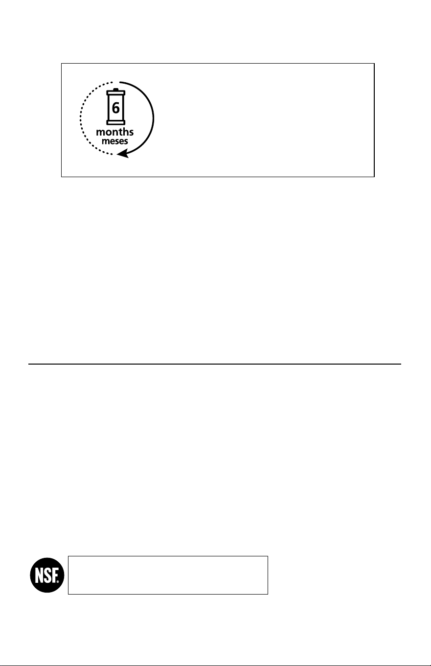
The recommended replacement frequency
for the AOW-2000 2-Stage Under Sink System
is every 6 months or every 500 gallons of use.
La frecuencia de cambio recomendada para el
sistema bajo el fregadero de 2 etapas AOW-2000 es
cada 6 meses o cada 1893litros (500galones) de uso.
A. O. Smith Corporation P.O. Box 1597 | Johnson City, TN 37605-1597 | 833.232.9711
AOW-2000_install_20190313
System Tested and Certied by NSF International against NSF/ANSI Standards
42, 53, & 401 and conforms to NSF protocol P473 for the reduction of the claims
specied on the performance data sheet and at www.nsf.org.
Sistema probado y certicado por NSF International según las normas NSF/ANSI 42, 53 y 401, y
conforme al protocolo P473 de NSF para la reducción de las declaraciones especicadas en la Hoja de
datos de rendimiento y en www.nsf.org.
This lter system is designed and tested for use with genuine A. O. Smith parts, including replacement lters, faucet and all
hardware. Use of parts from other manufacturers may result in loss of contaminant reduction performance, system damage
or failure. Use of parts from other manufacturers will also void your warranty. Please visit www.aosmith.com/wholesale for
replacement parts. Installation must comply with state and local ordinances.
A. O. Smith is not liable for consequential or incidental damages due to improper installation.
Este sistema de ltrado está diseñado y probado para ser usado con piezas originales de A. O. Smith, lo que incluye los ltros, la llave y todas
las piezas metálicas de repuesto. El uso de piezas de otros fabricantes puede generar una pérdida en el rendimiento de la reducción de
contaminantes, dañar el sistema o causar fallas. El uso de piezas de otros fabricantes también anulará su garantía. Visite www.aosmith.com/
wholesale para ver los repuestos. La instalación debe cumplir con las ordenanzas estatales y locales.
A. O. Smith no se hace responsable por daños indirectos o emergentes a causa de una instalación incorrecta.
Get the most out of your lter by using
only genuine A. O. Smith replacements.
Visit www.aosmith.com/wholesale
to nd replacements or call 833.232.9711
to speak to a Wholesale Representative.
Aproveche al máximo su ltro con los repuestos originales de A. O. Smith.