5
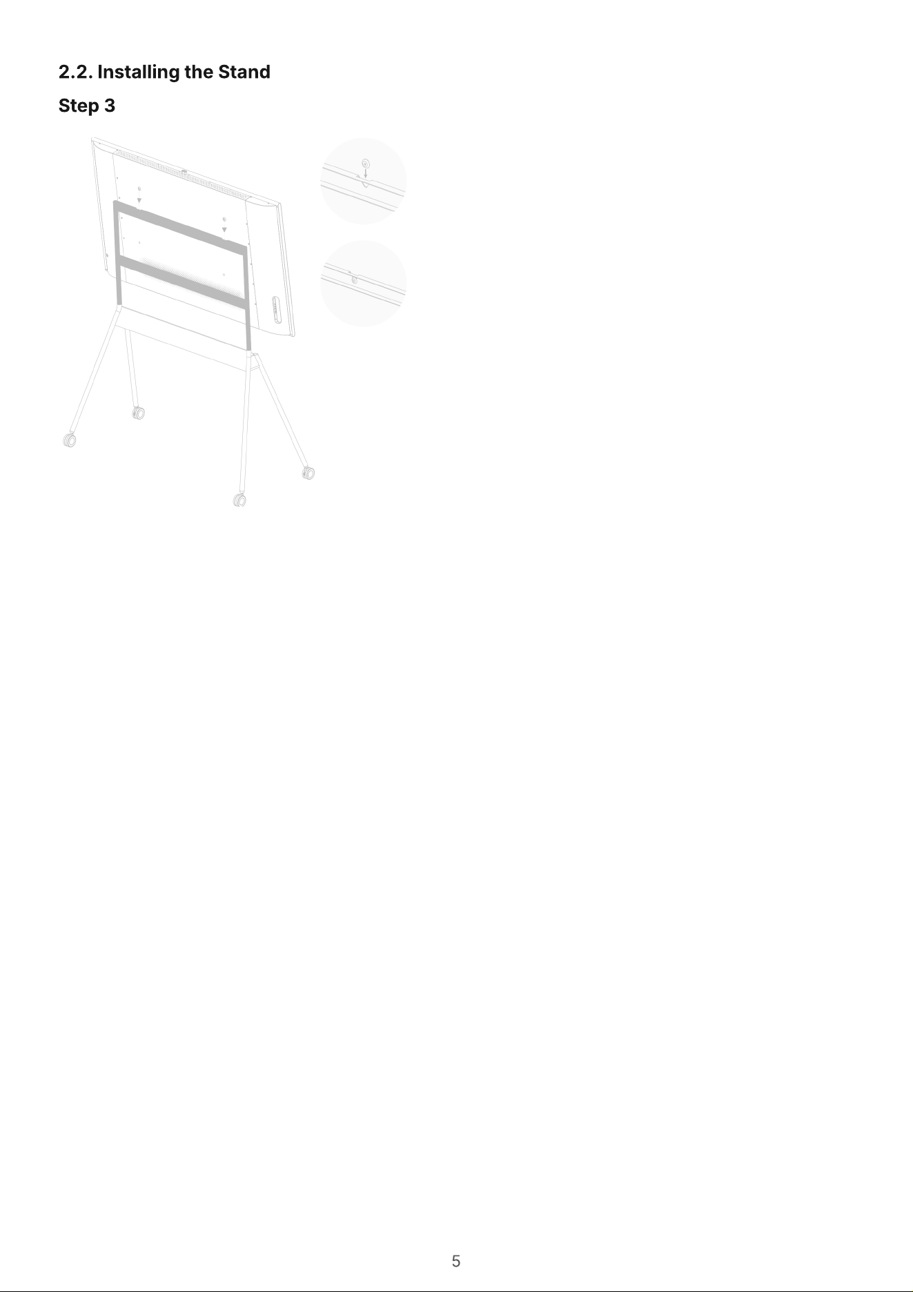
2.2. Installing the Stand
Step 3
6
Parts and Functions
3.1. Input/Output
7
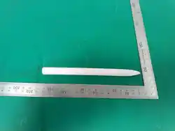
Vibe is equipped with an infrared touch display and can be operated by fingertips or a Vibe stylus. The
following descriptions illustrate typical operations. More Vibe software manuals and guides can be
found at https://knowledge.vibe.us.
The following operations can be done either with fingertip or Vibe stylus
Touch the target on the screen for one quick tap, then release
Touch and hold the target (e.g., an image or a Sticky-Note) on the screen
Touch the selected target and move across the screen without losing direct contact, then release when
reaching the new location.
Choose a tool or select an optio
Select an objec
Move an objec
Note: Avoid scratching with sharp objects on the touch display. Only use fingertips and the Vibe stylus
are for touch control.
Touch Control
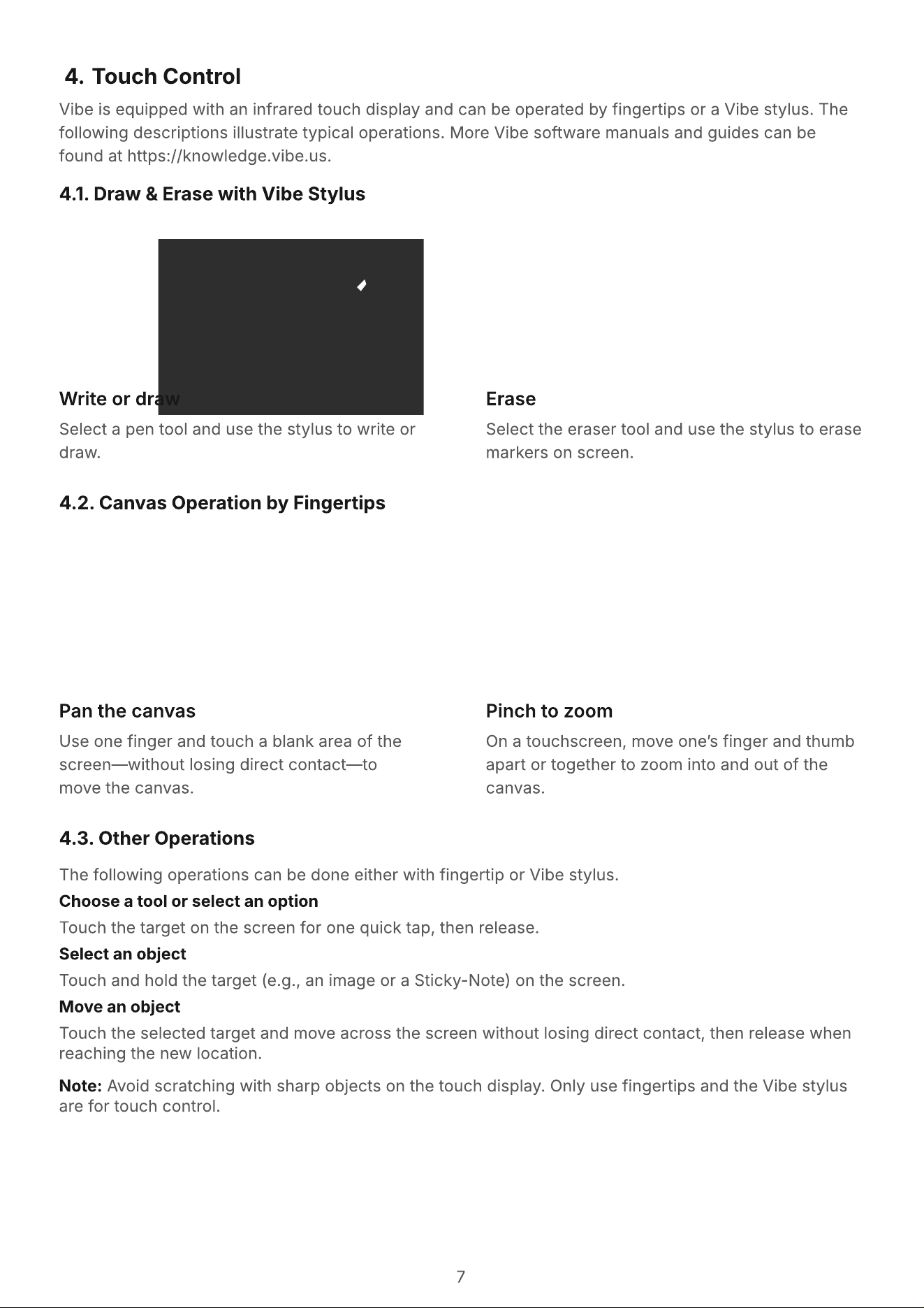
4.1. Draw & Erase with Vibe Stylus
4.2. Canvas Operation by Fingertips
4.3. Other Operations
Write or draw
Pan the canvas
Erase
Pinch to zoom
Select a pen tool and use the stylus to write or
draw.
U
se one finger and touch a blank area of the
screen
—
without losing direct contact
—
to
move the canvas.
Select the eraser tool and use the stylus to erase
markers on screen.
O
n a touchscreen
,
move one
’
s finger and thumb
apart or together to
z
oom into and out of the
canvas.
8
We strive to deliver the highest quality products and use some of the industry’s most advanced
manufacturing processes whilst practicing stringent quality control. However, pixel or sub-pixel defects
on the PDP / TFT panels used in Plasma & LCD displays are sometimes unavoidable. No manufacturer
can guarantee that all panels will be free from pixel defects, but can guarantee that any Plasma & LCD
displays with an unacceptable number of defects will be repaired during the warranty period in line with
your local warranty
This notice explains the different types of pixel defects and defines the acceptable defect level for the
LCD screen. To qualify for repair under warranty, the number of pixel defects must exceed a certain
level as shown in the reference table. If the LCD screen is within specification, a warranty exchange or
claim will be denied.
Pixel and sub-pixel defects appear on the screen in different ways. There are three categories of pixel
defects and several types of sub-pixel defects within each category
Dot definition = What is a defective “Dot”?
Black dot defects appear as pixels or sub-pixels that are always dark or “off.” These are the examples of
black dot defects:
Because pixel and sub-pixel defects of the same type that are nearby one another may be more
noticeable, there are specific tolerances for the proximity of pixel defects. In the table below you can
find specifications about
Allowed amount of adjacent dark dots (adjacent dark dots = 1 pair of dark dots
Minimum distance between dark dot
Total number of all defective dots
One or more defective, adjacent sub-pixel
are defined as one “dot”. The number of
defective sub-pixels are not relevant to
define a defective dot. This means that a
defective dot can consist of one, two or
three defective sub-pixels which can be
dark or lit.
One dot = One Pixel; consists
of three sub-pixels of Red,
Green, and Blue.
Pixel Defect Policy
5.1. Pixels and Subpixels
5.2. Types of Pixel Defects + Dot Definition
5.
3
. Da
rk
Dot Defects
5.
4
. P
r
oxi
m
ity of Pixel Defects
A pixel, or picture element, is composed of three sub-pixels in the primary
colors of red, green and blue. Many pixels together form an image. When
all sub-pixels of a pixel are lit, the three colored sub-pixels together
appear as a single white pixel. When all are dark, the three colored sub-
pixels together appear as a single black pixel. Other combinations of lit
and dark sub-pixels appear as single pixels of other colors.
9
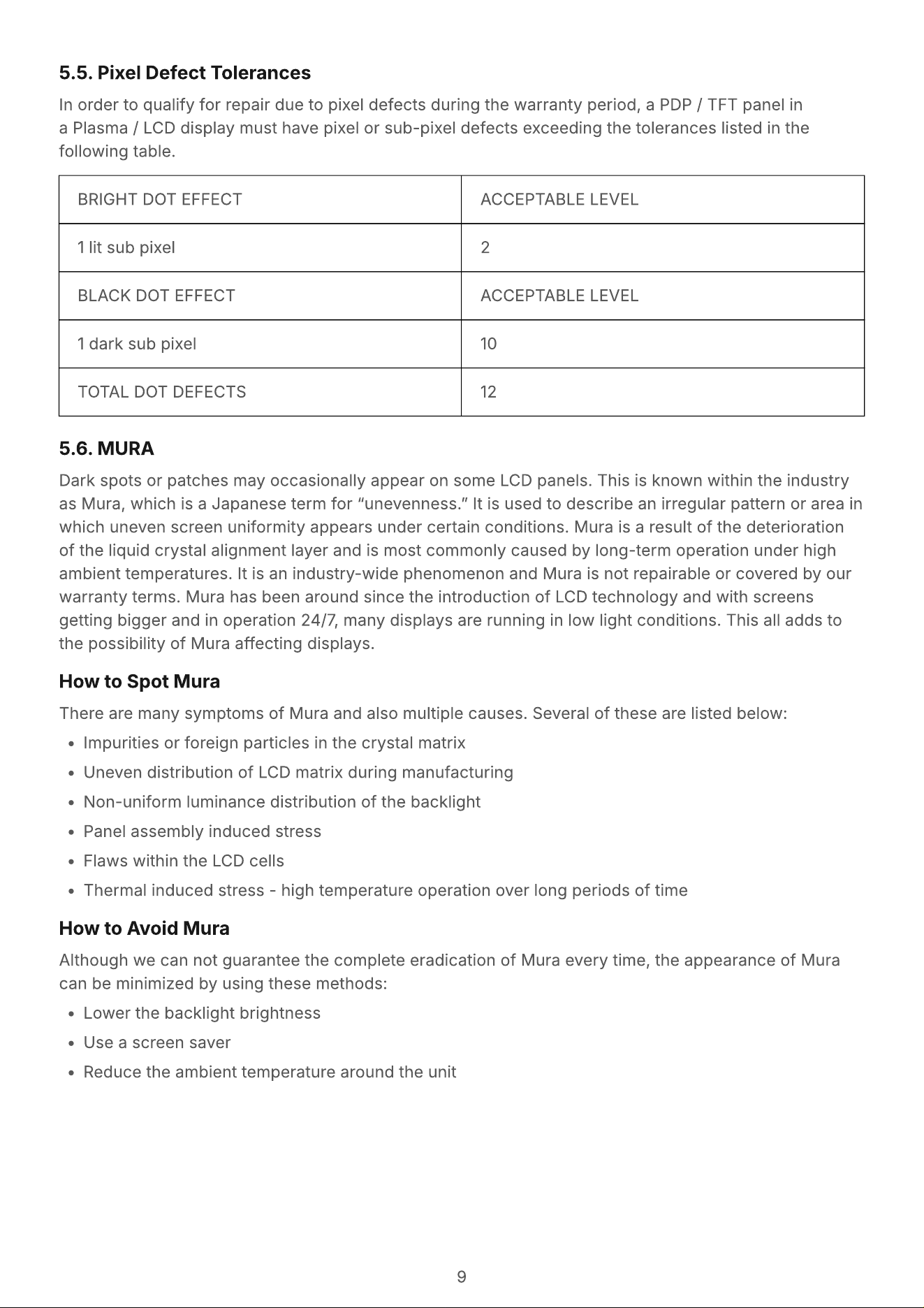
In order to qualify for repair due to pixel defects during the warranty period, a PDP / TFT panel in
a Plasma / LCD display must have pixel or sub-pixel defects exceeding the tolerances listed in the
following table.
Dark spots or patches may occasionally appear on some LCD panels. This is known within the industry
as Mura, which is a Japanese term for “unevenness.” It is used to describe an irregular pattern or area in
which uneven screen uniformity appears under certain conditions. Mura is a result of the deterioration
of the liquid crystal alignment layer and is most commonly caused by long-term operation under high
ambient temperatures. It is an industry-wide phenomenon and Mura is not repairable or covered by ou
warranty terms. Mura has been around since the introduction of LCD technology and with screens
getting bigger and in operation 24/7, many displays are running in low light conditions. This all adds to
the possibility of Mura affecting displays.
There are many symptoms of Mura and also multiple causes. Several of these are listed below
Impurities or foreign particles in the crystal matri
Uneven distribution of LCD matrix during manufacturin
Non-uniform luminance distribution of the backligh
Panel assembly induced stres
Flaws within the LCD cell
Thermal induced stress - high temperature operation over long periods of time
Although we can not guarantee the complete eradication of Mura every time, the appearance of Mura
can be minimized by using these methods
Lower the backlight brightnes
Use a screen save
Reduce the ambient temperature around the unit
How to Spot Mura
How to Avoid Mura
5.5. Pixel Defect Tolerances
5.6. MURA
BRIGHT DOT EFFECT ACCEPTABLE LEVEL
1 lit sub pixel 2
BLACK DOT EFFECT ACCEPTABLE LEVEL
1 dark sub pixel 10
TOTAL DOT DEFECTS 12
10
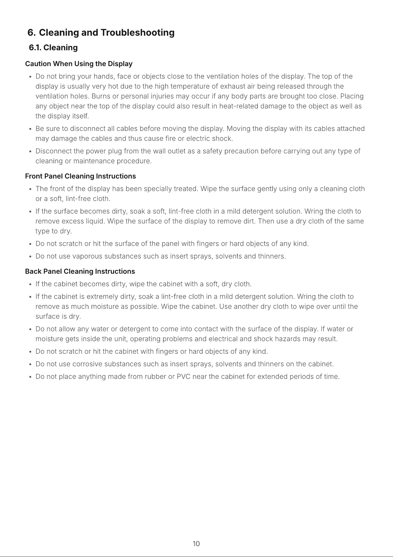
Caution When Using the Displa
Do not bring your hands, face or objects close to the ventilation holes of the display. The top of the
display is usually very hot due to the high temperature of exhaust air being released through the
ventilation holes. Burns or personal injuries may occur if any body parts are brought too close. Placing
any object near the top of the display could also result in heat-related damage to the object as well as
the display itself
Be sure to disconnect all cables before moving the display. Moving the display with its cables attached
may damage the cables and thus cause fire or electric shock
Disconnect the power plug from the wall outlet as a safety precaution before carrying out any type of
cleaning or maintenance procedure.
Front Panel Cleaning Instruction
The front of the display has been specially treated. Wipe the surface gently using only a cleaning cloth
or a soft, lint-free cloth
If the surface becomes dirty, soak a soft, lint-free cloth in a mild detergent solution. Wring the cloth to
remove excess liquid. Wipe the surface of the display to remove dirt. Then use a dry cloth of the same
type to dry
Do not scratch or hit the surface of the panel with fingers or hard objects of any kind
Do not use vaporous substances such as insert sprays, solvents and thinners.
Back Panel Cleaning Instruction
If the cabinet becomes dirty, wipe the cabinet with a soft, dry cloth
If the cabinet is extremely dirty, soak a lint-free cloth in a mild detergent solution. Wring the cloth to
remove as much moisture as possible. Wipe the cabinet. Use another dry cloth to wipe over until the
surface is dry
Do not allow any water or detergent to come into contact with the surface of the display. If water or
moisture gets inside the unit, operating problems and electrical and shock hazards may result
Do not scratch or hit the cabinet with fingers or hard objects of any kind
Do not use corrosive substances such as insert sprays, solvents and thinners on the cabinet
Do not place anything made from rubber or PVC near the cabinet for extended periods of time.
Cleaning and Troubleshooting
6.1. Cleaning
11
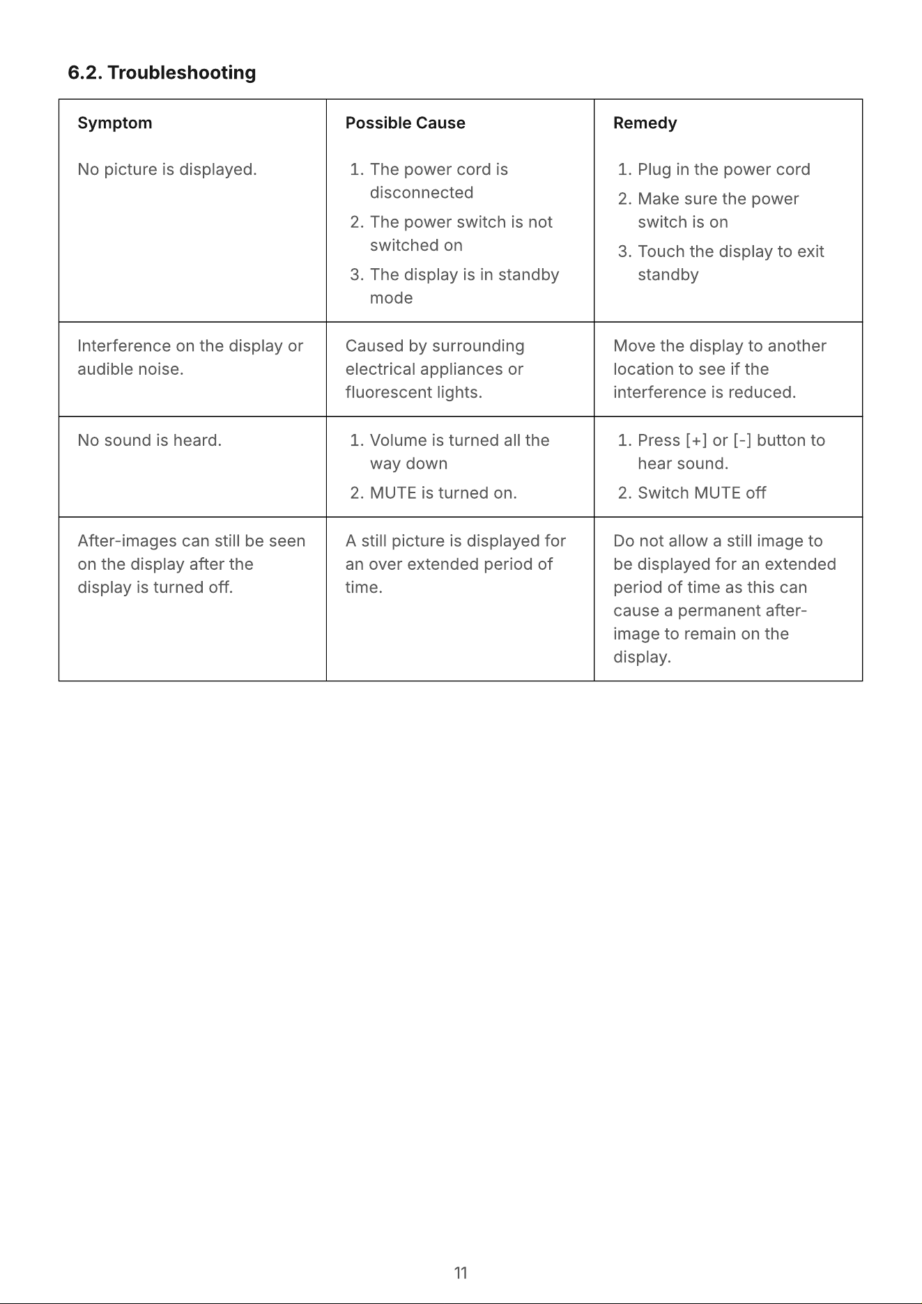
6.2. Troubleshooting
Sympto
No picture is displayed.
Possible Caus
The power cord is
disconnecte
The power switch is not
switched o
The display is in standby
mode
Remed
Plug in the power cor
Make sure the power
switch is o
Touch the display to exit
standby
Interference on the display or
audible noise.
Caused by surrounding
electrical appliances or
fluorescent lights.
Move the display to another
location to see if the
interference is reduced.
No sound is heard. Volume is turned all the
way dow
MUTE is turned on.
Press [+] or [-] button to
hear sound
Switch MUTE off
After-images can still be seen
on the display after the
display is turned off.
A still picture is displayed for
an over e
x
tended period of
time.
D
o not allow a still image to
be displayed for an e
x
tende
period of time as this can
cause a permanent after-
image to remain on the
display.
12
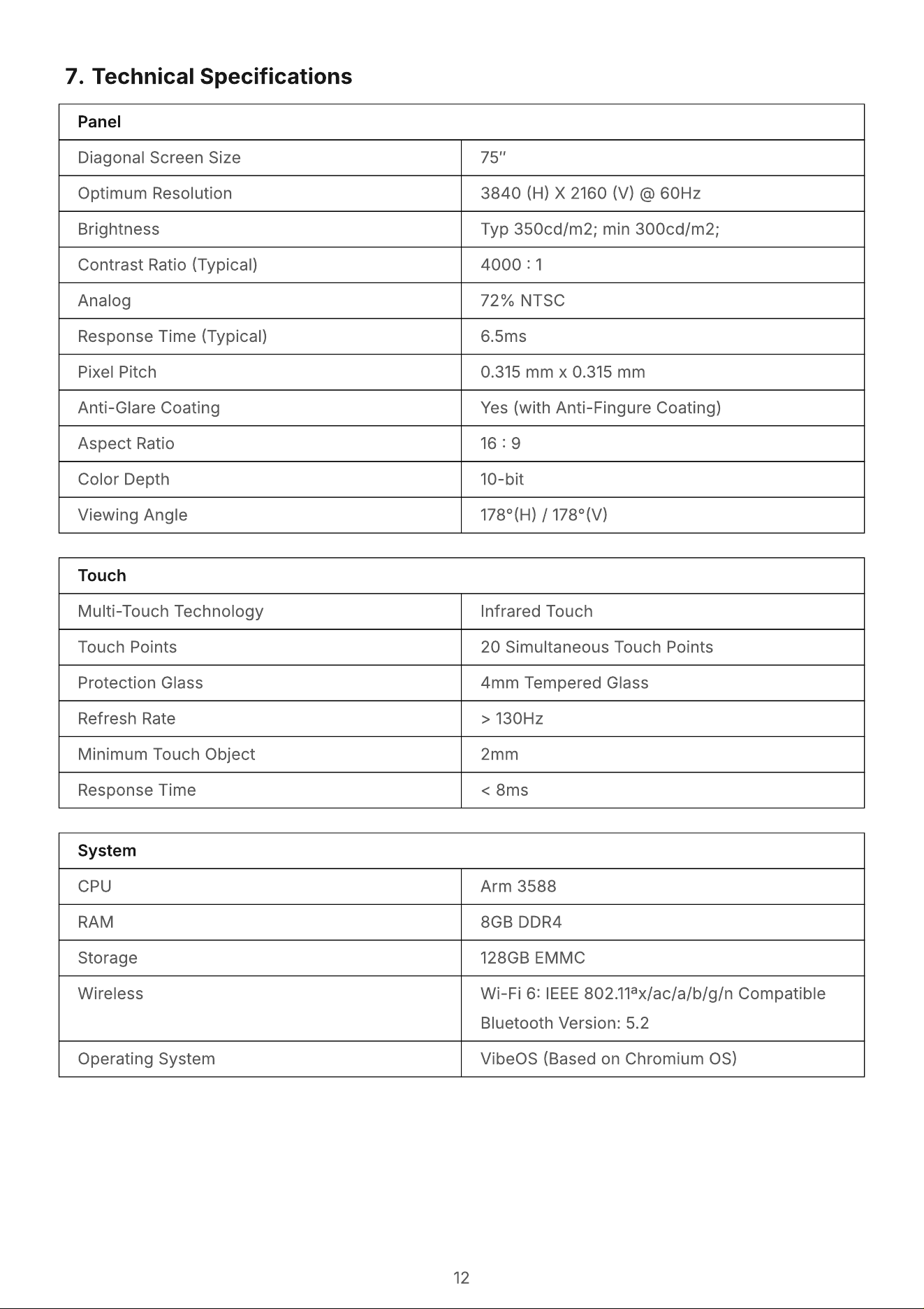
Technical Specifications
Panel
Diagonal Screen Size 75″
Optimum Resolution 3840 (H) X 2160 (V) @ 60Hz
Brightness Typ 350cd/m2; min 300cd/m2;
Contrast Ratio (Typical) 4000 : 1
Analog 72% NTSC
Response Time (Typical) 6.5ms
Pixel Pitch 0.315 mm x 0.315 mm
Anti-Glare Coating Yes (with Anti-Fingure Coating)
Aspect Ratio 16 : 9
Color Depth 10-bit
Viewing Angle 178°(H) / 178°(V)
Touch
Multi-Touch Technology Infrared Touch
Touch Points 20 Simultaneous Touch Points
Protection Glass 4mm Tempered Glass
Refresh Rate > 130Hz
Minimum Touch Object 2mm
Response Time < 8ms
Syst
e
m
CP
U
Arm 3588
RAM 8GB DDR4
Storage 128GB
E
MMC
W
ireless
W
i-Fi 6: I
EEE
802.11
a
x/ac/a/b/g/n Compatibl
Bluetooth Version
:
5.2
Operating System VibeOS (Based on Chromium OS)
13
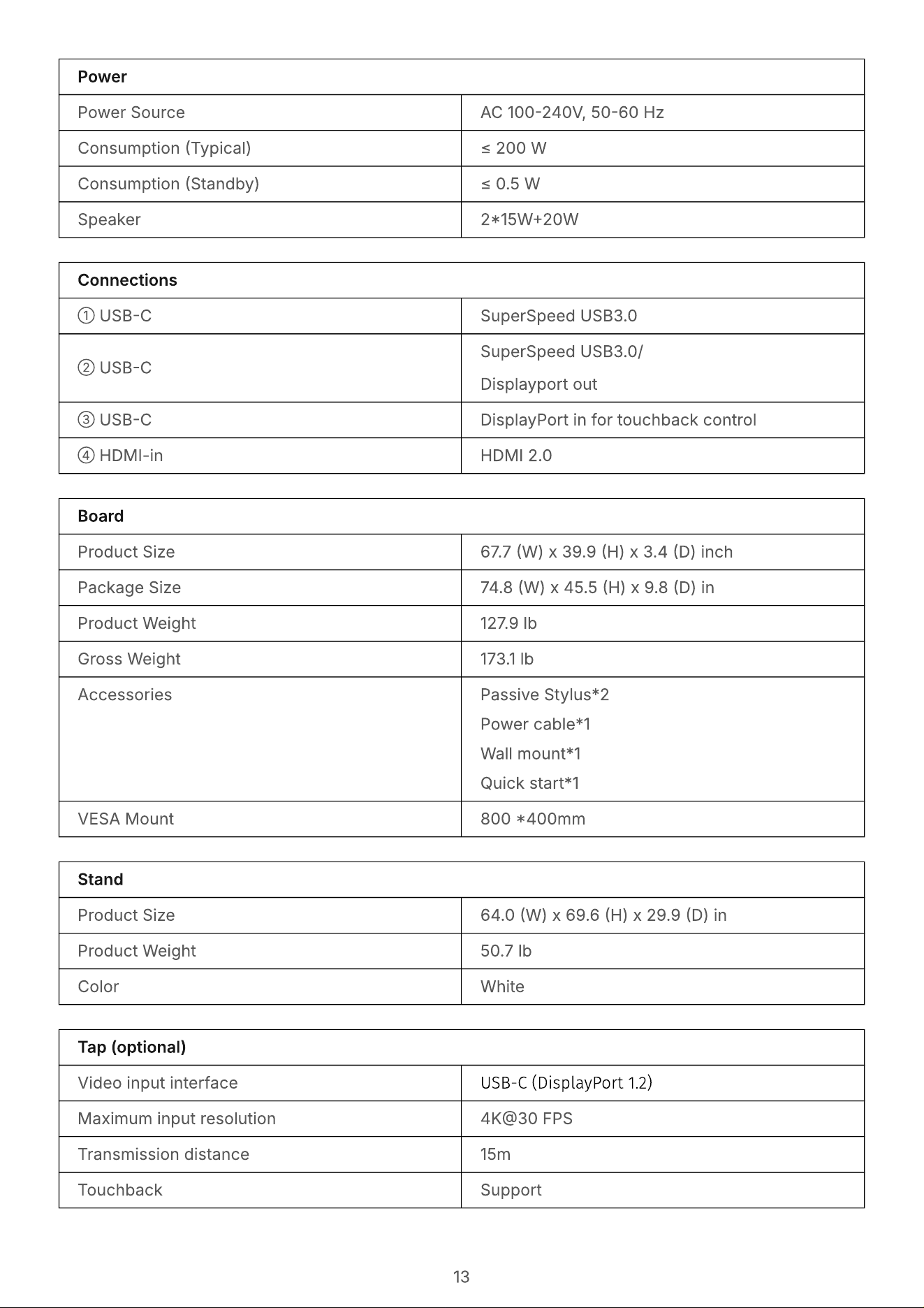
Power
Power Source AC 100-240V, 50-60 Hz
Consumption (Typical) ≤ 200 W
Consumption (Standby) ≤ 0.5 W
Speaker 2*15W+20W
Board
Product Size 67.7 (W) x 39.9 (H) x 3.4 (D) inch
Package Size 74.8 (W) x 45.5 (H) x 9.8 (D) in
Product Weight 127.9 lb
Gross Weight 173.1 lb
Accessories Passive Stylus*
Power cable*
Wall mount*
Quick start*1
VESA Mount 800 *400mm
Stand
Product Size 64.0 (W) x 69.6 (H) x 29.9 (D) in
Product Weight 50.7 lb
Color White
Tap (optional)
Video input interface USB-C (DisplayPort 1.2)
Maximum input resolution 4K@30 FPS
Transmission distance 15m
Touchback Support
Connections
①
U
S
B
-C SuperSpeed
U
S
B
3.0
②
U
S
B
-C
SuperSpeed
U
S
B
3.0
Displayport out
③
U
S
B
-C DisplayPort in for touchback control
④
HDM
I-
in HDM
I
2.0
14
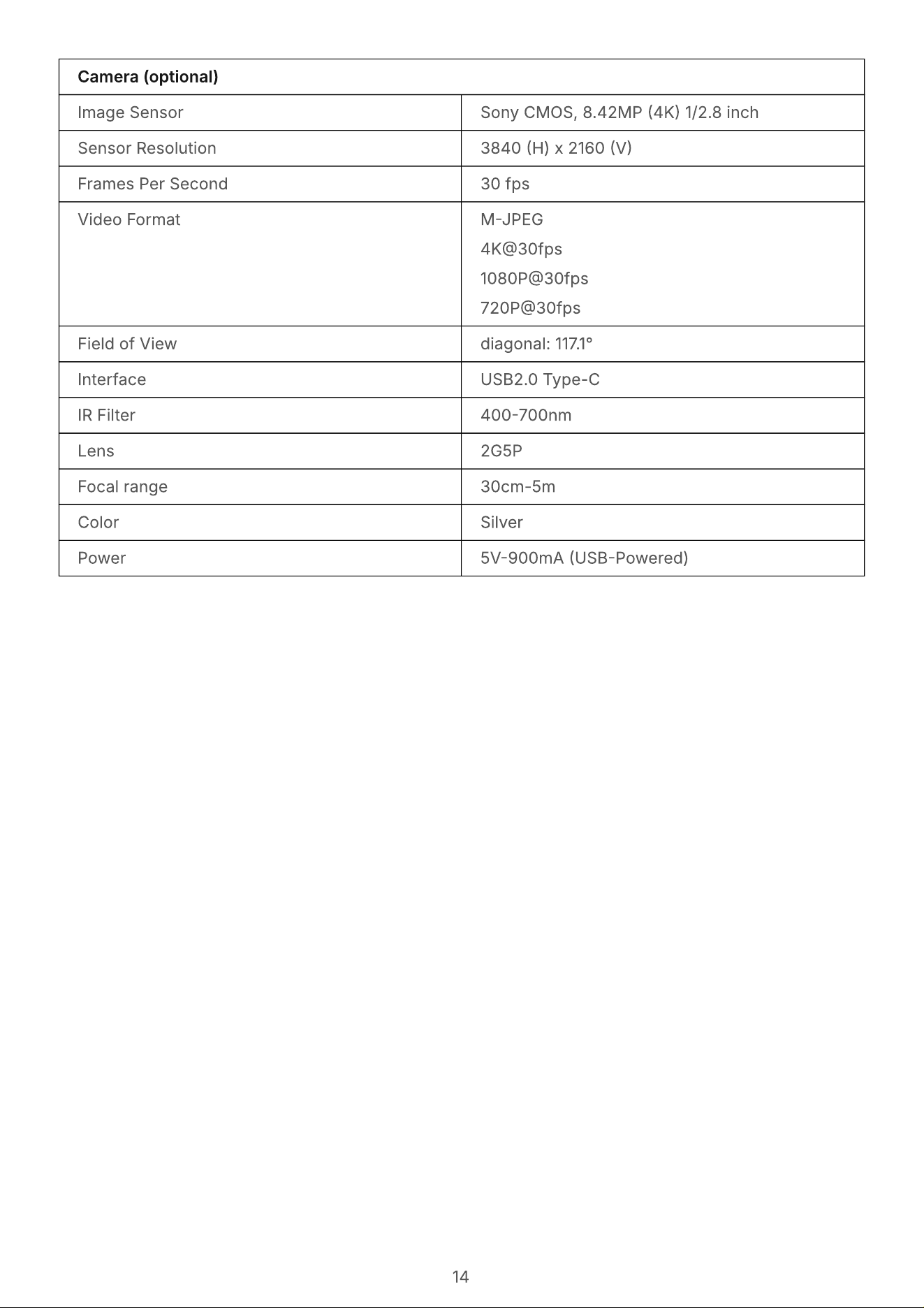
Camera (optional)
Image Sensor Sony CMOS, 8.42MP (4K) 1/2.8 inch
Sensor Resolution 3840 (H) x 2160 (V)
Frames Per Second 30 fps
Video Format M-JPE
4K@30fp
1080P@30fp
720P@30fps
Field of View diagonal: 117.1°
Interface USB2.0 Type-C
IR Filter 400-700nm
Lens 2G5P
Focal range 30cm-5m
Color Silver
Power 5V-900mA (USB-Powered)

Vibe Inc.
+1 (864) 335-200
https://vibe.u
2018 156th Ave NE, Office 165 Bellevue, WA 98007
Vibe Interactive Whiteboar
Designed by Vibe Inc in Seattle U.S. Made in China