WELLS MANUFACTURING
265 Hobson Street, Smithville, Tennessee 37166
telephone: 800-264-7827
www.wells-mfg.com
IMPORTANT: DO NOT DISCARD THIS MANUAL
This manual is considered to be part of the appliance and is to be given to the OWNER or
MANAGER of the restaurant, or to the person responsible for TRAINING OPERATORS of
this appliance. Additional manuals are available from your WELLS DEALER.
THIS MANUAL MUST BE READ AND UNDERSTOOD BY ALL PERSONS USING OR
INSTALLING THIS APPLIANCE. Contact your WELLS DEALER if you have any
questions concerning installation, operation or maintenance of this equipment.
2M-304964 REV G (04-22) M506
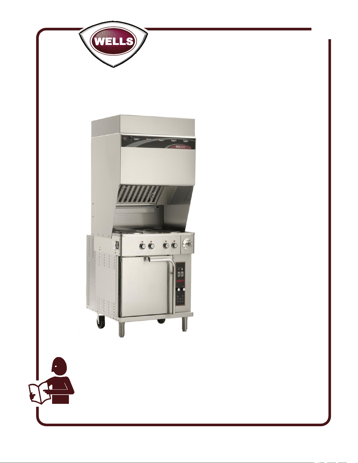
Model
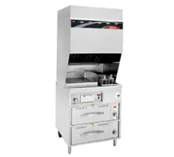
WVOC-4HF
OWNERS MANUAL
WVOC- 4 SERIES
CONVECTION OVEN
and
4 HOTPLATE COOKTOP
with
UNIVERSAL
HOOD
MODELS:
WVO4HF
WVO4HS
Includes
INSTALLATION
USE & CARE
EXPLODED VIEW
PARTS LIST
WIRING DIAGRAM
506

M506 2M-304964 Owners Manual WVOC-4H
Unless otherwise specied, all commercial cooking
equipment manufactured by Wells Manufacturing is
warranted against defects in materials and workmanship
for a period of one year from the date of original installation
or 18 months from the date of shipment from our factory,
whichever comes rst, and is for the benet of the original
purchaser only.
THIS WARRANTY IS THE COMPLETE AND ONLY
WARRANTY, EXPRESSED OR IMPLIED IN LAW
OR IN FACT, INCLUDING BUT NOT LIMITED TO,
WARRANTIES OF MERCHANTABILITY OR FITNESS
FOR ANY PARTICULAR PURPOSE, AND/OR FOR
DIRECT, INDIRECT OR CONSEQUENTIAL DAMAGES
IN CONNECTION WITH WELLS MANUFACTURING
PRODUCTS. This warranty is void if it is determined
that, upon inspection by an authorized service agency,
the equipment has been modied, misused, misapplied,
improperly installed, or damaged in transit or by re, ood
or act of God. It also does not apply if the serial nameplate
has been removed, or if service is performed by unauthorized
personnel. The prices charged by Wells Manufacturing for
its products are based upon the limitations in this warranty.
Seller’s obligation under this warranty is limited to the
repair of defects without charge by a Wells Manufacturing
factory authorized service agency or one of its sub-service
agencies. This service will be provided on customer’s
premises for non-portable models. Portable models (a
device with a cord and plug) must be taken or shipped to the
closest authorized service agency, transportation charges
prepaid, for service. In addition to restrictions contained
in this warranty, specic limitations are shown in the
Service Policy and Procedure Guide. Wells Manufacturing
authorized service agencies are located in principal cities.
This warranty is valid in the United States and Canada and
void elsewhere. Please consult your classied telephone
directory, your foodservice equipment dealer or contact:
Wells Manufacturing
10 Sunnen Dr., St. Louis MO 63143 USA
phone (314) 678-6314 or fax (314) 781-2714
for information and other details concerning warranty.
LIMITED WARRANTY STATEMENT
SERVICE POLICY AND PROCEDURE GUIDE and ADDITIONAL WARRANTY EXCLUSIONS
NOTE: For your protection, please note that equipment
in this shipment was carefully inspected and packaged
by skilled personnel before leaving the factory. Upon
acceptance of this shipment, the transportation company
assumes full responsibility for its safe delivery.
IF SHIPMENT ARRIVES DAMAGED:
1. VISIBLE LOSS OR DAMAGE: Be certain that any
visible loss or damage is noted on the freight bill or
express receipt, and that the note of loss or damage is
signed by the delivery person.
2. FILE CLAIM FOR DAMAGE IMMEDIATELY:
Regardless of the extent of the damage.
3. CONCEALED LOSS OR DAMAGE: if damage is
unnoticed until the merchandise is unpacked, notify the
transportation company or carrier immediately, and le
“CONCEALED DAMAGE” claim with them. This
should be done within fteen (15) days from the date
the delivery was made to you. Be sure to retain the
container for inspection.
Wells Manufacturing cannot assume liability for damage or
loss incurred in transit. We will, however, at your request,
supply you with the necessary documents to support your
claim.
SHIPPING DAMAGE CLAIM PROCEDURE
xi
1. Resetting of safety thermostats, circuit breakers, over
load protectors, and/or fuse replacements are not
covered by this warranty unless warranted conditions
are the cause.
2. All problems due to operation at voltages or phase
other than specied on equipment nameplates are
not covered by this warranty.
Conversion to correct voltage and/or phase must be
the customer’s responsibility.
3. All problems due to electrical connections not made
in accordance with electrical code requirements
and wiring diagrams supplied with the equipment are
not covered by this warranty.
4. Replacement of items subject to normal wear, to
include such items as knobs, light bulbs; and, normal
maintenance functions including adjustments of
thermostats, adjustment of micro switches and
replacement of fuses and indicating lights are not
covered by warranty.
5. Damage to electrical cords and/or plug due to exposure
to excessive heat are not covered by this warranty.
6. Full use, care, and maintenance instructions supplied
with each machine. Noted maintenance and
preventative maintenance items, such as servicing and
cleaning schedules, are customer responsibility. Those
miscellaneous adjustments noted are customer
responsibility. Proper attention to preventative
maintenance and scheduled maintenance procedures
will prolong the life of the appliance.
7. Travel mileage is limited to sixty (60) miles from an
Authorized Service Agency or one of its sub-service
agencies.
8. All labor shall be performed during regular working
hours. Overtime premium will be charged to the buyer.
9. All genuine Wells replacement parts are warranted
for ninety (90) days from date of purchase on non-
warranty equipment. This parts warranty is limited only
to replacement of the defective part(s). Any use of
non-genuine Wells parts completely voids any
warranty.
10. Installation, labor, and job check-outs are not
considered warranty and are thus not covered by this
warranty.
11. Charges incurred by delays, waiting time or operating
restrictions that hinder the service technician’s ability to
perform service are not covered by warranty. This
includes institutional and correctional facilities.
Thank You for purchasing this Wells Manufacturing appliance.
Proper installation, professional operation and consistent maintenance of this appliance will ensure that
it gives you the very best performance and a long, economical service life.
This manual contains the information needed to properly install this appliance, and to use and care for
the appliance in a manner which will ensure its optimum performance.
TABLE OF CONTENTS
SPECIFICATIONS
INTRODUCTION
1
WARRANTY ................................................................ xi
SPECIFICATIONS ....................................................... 1
FEATURES & OPERATING CONTROLS ................... 2
PRECAUTIONS & GENERAL INFORMATION ............ 6
AGENCY LISTING INFORMATION ............................. 7
INSTALLATION ........................................................... 8
OPERATION ................................................................ 13
CLEANING INSTRUCTIONS ....................................... 18
TROUBLESHOOTING SUGGESTIONS ..................... 22
MAINTENANCE INSTRUCTIONS ............................... 23
MSDS (Ansulex Low pH) ............................................. 26
MAINTENANCE SCHEDULES .................................... 28
ANSUL® COMPONENTS ........................................... 30
EXPLODED VIEW & PARTS LIST .............................. 31
WIRING DIAGRAM ...................................................... 36
PARTS & SERVICE....................................................... 41
CUSTOMER SERVICE DATA ..................................... 41
M506 2M-304964 Owners Manual WVOC-4H
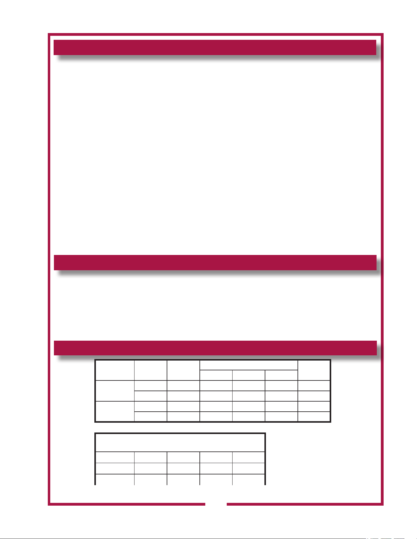
MODEL VOLTS WATTS
AMPS 3ø
AMPS 1ø
L1 L2 L3
WVO4HF
208 11,500 32 31 26 n/a
240 14,100 36 35 30 n/a
WVO4HS
208 12,500 36 35 34 n/a
240 16,500 41 40 39 n/a
Minimum clearances required from unit to nearest
combustible surface or object.
BACK SIDE BOTTOM TOP
inches n/a 6 6 19
millimeters n/a 152 152 483

FEATURES & OPERATING CONTROLS
Fig. 1 Ventilator Section Features & Operating Controls
2
M506 2M-304964 Owners Manual WVOC-4H
FEATURES & OPERATING CONTROLS (continued)
3
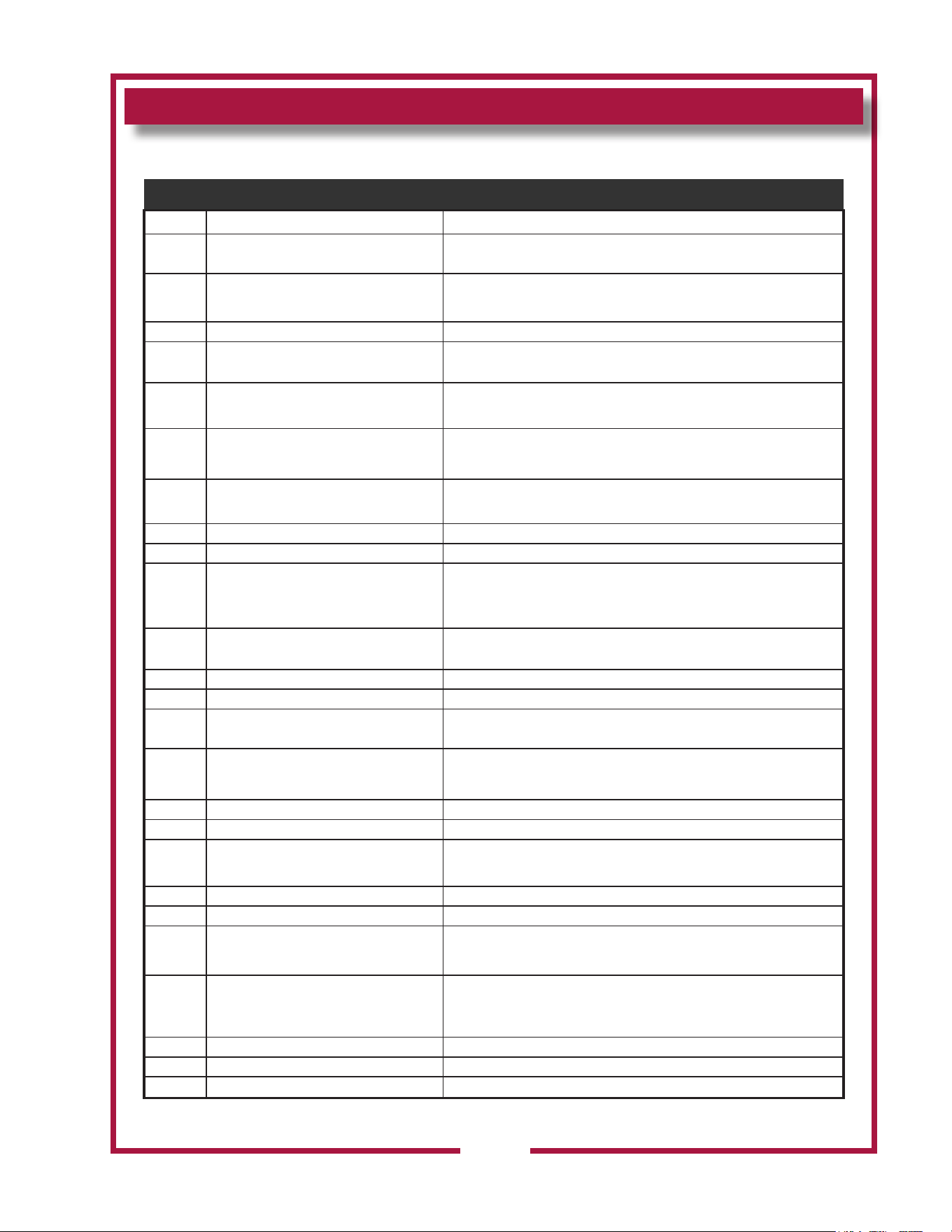
VENTILATOR SECTION
ITEM DESCRIPTION COMMENT
1 NAMEPLATE
Gives Manufacturer, Model and Serial Number information.
Also lists electrical specications.
a6.
FIRE SUPPRESSION
AGENT TANK (1.5 gal.)
Container for Ansulex™ Low-pH liquid re suppression liquid.
8 ADJUSTABLE (FRONT) LEG Allows the unit to be leveled.
9 RIGID (REAR) CASTER
Allows the unit to be easily positioned by lifting the front of the unit
slightly.
a10. MANUAL PULL STATION
Provides a means of manual activation of the re suppression
system. PULL ONLY IN CASE OF FIRE!
a11. FUSIBLE LINKS
Automatically activates re suppression system in the event of re
on the cooktop.
12 LOWER REAR ACCESS PANEL
Allows access to Ansul® re suppression agent tank (a6) and
controls also access to main power contactor (41).
a15. DISCHARGE NOZZLE Fire suppression media discharges here (2 places).
16 GREASE BAFFLE Extracts and drains most grease and moisture from the air ow.
18 PRE-FILTER ASSEMBLY
Comprises the PRE-FILTER FRAME and a replaceable PRE-
FILTER. Stops larger particles of grease from reaching the FILTER
PACK for reduced maintenance costs.
19 HEPA/CHARCOAL FILTER PACK
Stops most grease and smoke particles. Also assists in some
cooking odor removal.
22 GREASE CUP Collects grease/moisture drained from grease trough (23).
23 GREASE TROUGH Directs grease/moisture removed by grease bafe to grease cup.
28 VENTILATOR EXHAUST DUCT
Exit point for ventilator airow - on top left rear of unit.
DO NOT BLOCK
a31. STATUS INDICATOR
Displays status of re suppression system (COCKED - FIRED) If
FIRED, a buzzer will sound continuously.
38 POWER CORD 6’ cord and cap. Plug for NEMA 15-60R (receptacle by user).
40 FUSES Provide over-current protection of cooking appliance.
41 POWER CONTACTOR
Energizes cooktop only while ventilator section is sensed as
operational.
42 BUILDING FIRE ALARM RELAY Reports re alarm condition to building re management system.
43 GROUND LUG Ground wire of power cord connects here.
44 INTERLOCK TERMINAL
Provides connection for shut-down control by building re
management system.
53 FILTER INTERLOCK SWITCHES
Proper installation of grease bafe and lter pack close these
switches in ventilator sensor circuit. Provides air movement for
ventilation.
56 VENTILATOR FAN Provides air movement for ventilation.
58 SIDE SPACERS Maintain required 6: spacing from combustible surfaces.
70 COOLING FAN Provides cooling for cooktop controls.
M506 2M-304964 Owners Manual WVOC-4H
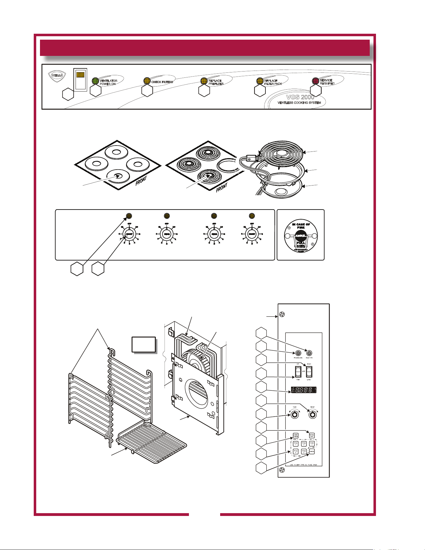
FEATURES & OPERATING CONTROLS (continued)
Fig. 2 Ventilator Section Controls & Indicator Lights
Fig. 4 Convection Oven Operating Features & Controls
Fig. 3 Cooktop Section Controls & Indicator Lights
V1
V2 V3 V4 V5 V6
4
IL2910
INSIDE
OVEN
RACK SUPPORTS
OVEN RACK
FAN
BAFFLE
HEATING
ELEMENTS
BLOWER
FAN
C.04
C.03
C.02
C.01
C.05
C.06
C.07
C.08
C.09
C.10
C.11
CONTROL
PANEL
IL2911
ANSUL®
PULL STATION
CONTROL
PANEL
TRIM RING
HEATING
ELEMENT
SPIRAL-TYPE
HEATING
ELEMENT
SOLID
PLATE
HEATING
ELEMENT
WVOC-4HF COOKTOP WVOC-4HS COOKTOP
DRIP PAN
H.01 H.02
M506 2M-304964 Owners Manual WVOC-4H
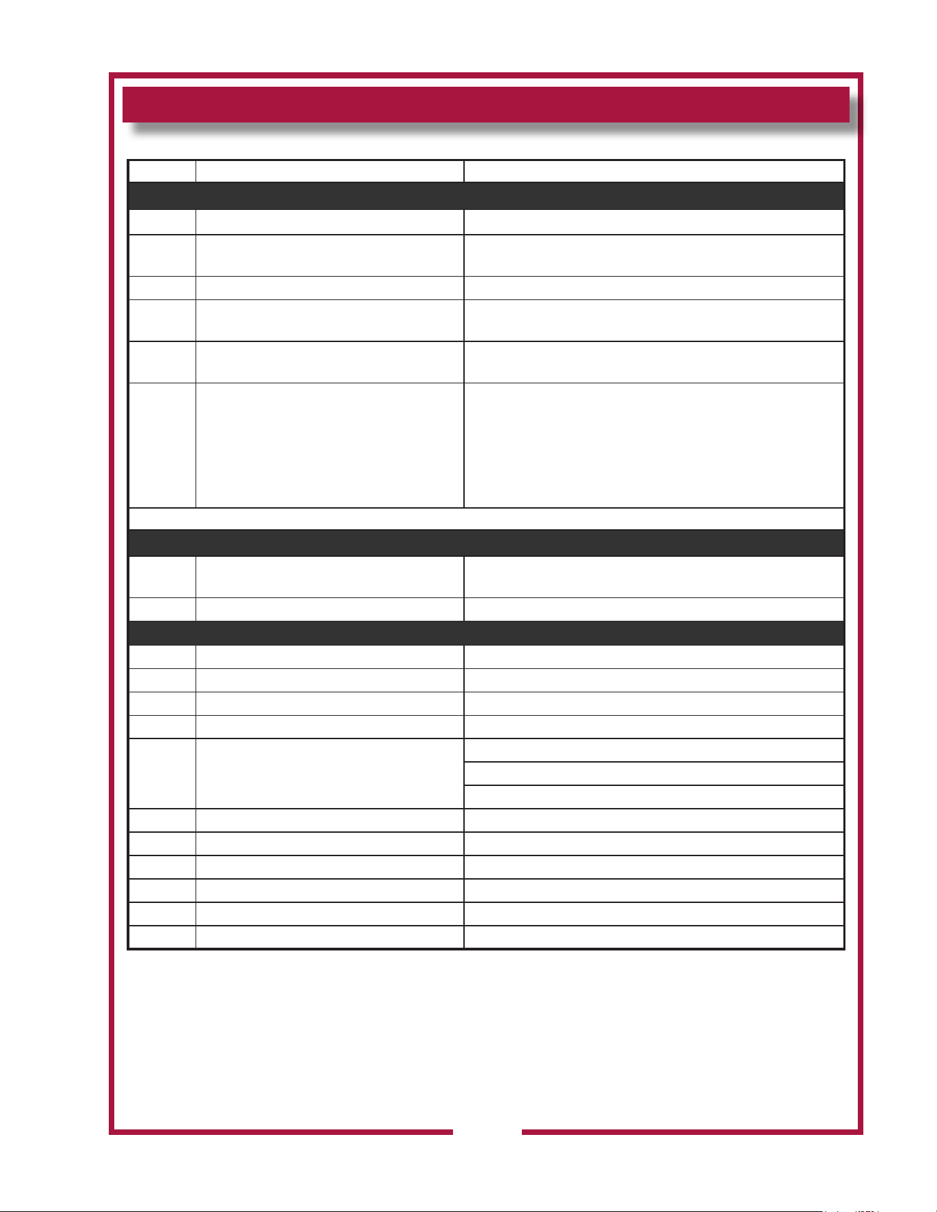
FEATURES & OPERATING CONTROLS (continued)
5
Item NO. Description Comments
VENTILATOR SECTION CONTROLS
V1 POWER SWITCH
V2 POWER ON INDICATOR
Energizes blower motor. If, after 10 seconds, proper conditions
are met, cooktop is energized.
V3 CHECK FILTERS ALARM INDICATOR GREEN. Glows when POWER switch is ON.
V4* REPLACE PREFILTER ALARM INDICATOR
AMBER. Glows if one or more lters are out of position.
Check all lters and bafes for proper installation.
V5* REPLACE FILTER PACK ALARM INDICATOR
AMBER. Glows when PREFILTER is approaching the end of its
service life and must soon be replaced.
V6* SERVICE REQUIRED ALARM INDICATOR
AMBER. Glows when FILTER PACK is approaching the end of
its service life and must soon be replaced. RED. Glows when
PREFILTER and/or FILTER PACK has reached the end of its
service life and is too loaded to allow sufcient air ow. Filter
MUST be replaced. Appliance is SHUT DOWN until expended
lters are replaced.
* See PRECAUTIONS & GENERAL INFORMATION, pages 6 & 7 for special procedures regarding prelters and lter packs.
COOKTOP SECTION CONTROLS - HOTPLATE
H.01 POWER ON INDICATOR
AMBER. Glows when associated temperature control is turned
ON.
H.02 HOTPLATE CONTROL Innite switch control of temperature of one hotplate section.
CONVECTION OVEN SECTION CONTROLS
C.01 POWER-OFF-FAN SWITCH Switch to turn oven ON, OFF or select FAN only.
C.02 FAN LOW-OFF-HIGH SWITCH Switch to turn fan ON, and to select fan speed.
C.03 OVEN POWER INDICATOR AMBER. Glows when oven is turned ON.
C.04 HEAT INDICATOR AMBER. Glows when heating elements are energized.
C.05 DIGITAL DISPLAY
Displays time and temperature information.
Time remaining in program (minute : second)
Programmed temperature (ºF)
C.06 OVEN TIME CONTROL Adjust programmed cooking time.
C.07 OVEN TEMP CONTROL Adjust programmed cooking temperature.
C.08 START TIMER KEY Begin a timed cook cycle.
C.09 ACTUAL TEMP KEY Press to display current oven temperature.
C.10 PGM KEYS Press to select pre-programmed time/temperature.
C.11 CANCEL KEY Press to cancel a program in progress.
M506 2M-304964 Owners Manual WVOC-4H
NOTE: Fire suppression system and all associated components
must only be serviced by an authorized Ansul® Distributor. All setup,
charging, repair and/or adjustment of the re suppression system must
be performed by an Authorized Ansul® Distributor ONLY.
IMPORTANT: If a remote pull station is installed, both rear casters
(9) must be replaced with legs to deter moving the unit. MOVING AN
APPLIANCE WITH A REMOTE PULL STATION WILL DISCHARGE
THE FIRE SUPPRESSION SYSTEM.
This Ventless Cooking System™ is designed to help reduce odor
emissions, but will not completely eliminate cooking odors. Air
exchange at the installation site must comply with the requirements of
the local jurisdictional authority. To ensure that odors do not build-up,
recommended minimum air exchange is 300 - 400 cfm of outside air
into and out of the area where the unit is used. Recommend use of
wall fan and wall switch, to be supplied by user.
This appliance is intended for use in commercial establishments
only.
This appliance is intended
to prepare food for human consumption.
No other use is
recommended or authorized by the manufacturer or its
agents.
Operators of this appliance must be familiar with the appliance use,
limitations and associated restrictions. Operating instructions must be
read and understood by all persons using or installing this appliance.
Cleanliness of this appliance is essential to good sanitation. Read and
follow all included cleaning instructions and schedules to ensure the
safety of the food product.
Disconnect this appliance from electrical power before performing any
maintenance or servicing.
Do not splash or pour water on, in or over any exposed element,
control, control panel or wiring.
DO NOT submerge pre-lter or lter pack in water.
The technical content of this manual, including any wiring diagrams,
schematics, parts breakdown illustrations and/or adjustment
procedures, is intended for use by qualied technical personnel.
Any procedure which requires the use of tools must be performed by a
qualied technician.
This manual is considered to be a permanent part of the appliance.
This manual and all supplied instructions, diagrams, schematics, parts
breakdown illustrations, notices and labels must remain with the
appliance if it is sold or moved to another location.
This appliance is made in the USA. Unless otherwise noted, this
appliance has American sizes on all hardware.
PRECAUTIONS AND GENERAL INFORMATION
WARNING:
SHOCK HAZARD
All servicing requiring access
to non-insulated electrical
components must be
performed by a factory
authorized technician.
DO NOT open any access
panel which requires the use
of tools. Failure to follow this
warning can result in severe
electrical shock.
CAUTION:
RISK OF
DAMAGE
DO NOT connect or energize
this appliance until all
installation instructions are
read and followed. Damage
to the appliance will result if
these instructions are not
followed.
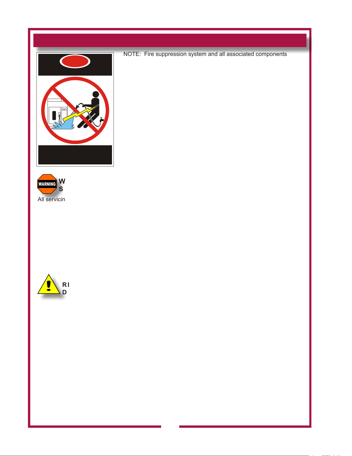
DANGER
ELECTRIC SHOCK HAZARD
DO NOT SPRAY WATER ON OR AROUND
ELECTRICAL EQUIPMENT
DO NOT WASH FLOOR NEAR ELECTRICAL
EQUIPMENT WITH WATER SPRAY
6
M506 2M-304964 Owners Manual WVOC-4H
AGENCY LISTING INFORMATION
STD 4
E146882
OPERATIONAL NOTES:
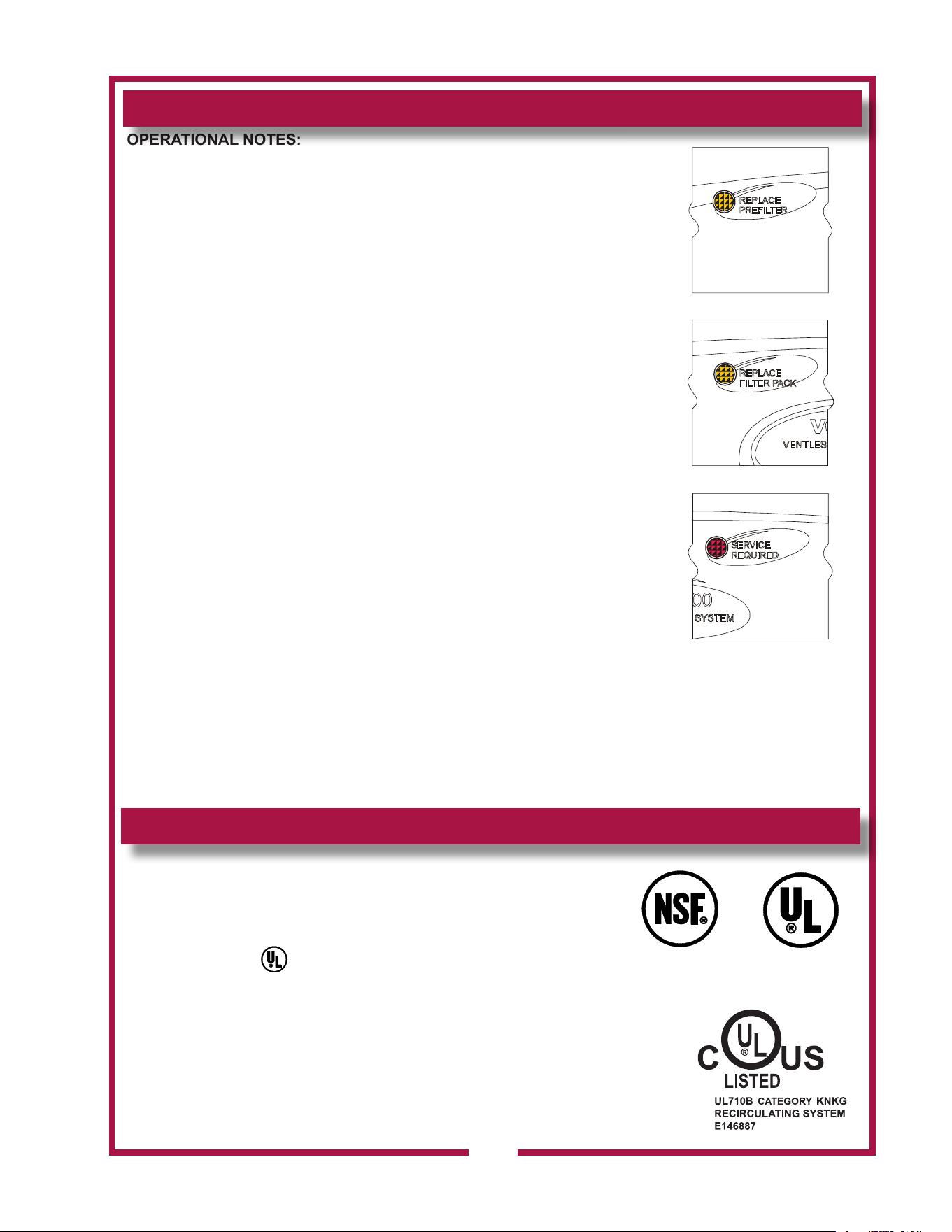
REPLACE PREFILTER and REPLACE FILTER PACK indicator lights
provide a timely warning that a system shut-down is imminent.
The actual time between the indicator light coming on and the loss of
cooking appliance power will depend upon the cooking conditions.
Anytime a dirty PRE-FILTER is replaced, the system airow will
increase. If the condition of the FILTER PACK is marginal, the
REPLACE FILTER PACK light could then come on. If this happens,
a fresh FILTER PACK must be installed within a reasonably short time.
Use only genuine Wells replacement parts and lters, call
(314) 678-6314 or your authorized Wells service agent. Parts supplied
by others will void your warranty and may not provide safe operation.
Loss of airow through the old lter pack will soon cause a system
shut-down when the airow falls below minimum vapor capture levels.
KEEP SPARE FILTER PACKS ON HAND.
IMPORTANT: If you decide to “get the most” out of the old lter pack,
and continue to use it until a system shut-down happens, it is advisable
to have a fresh lter pack readily at hand, and have someone available
who is capable of replacing it. Otherwise, you may experience an
extended down time, with consequent associated loss of business.
The manufacturer assumes no liability for loss of business due to
a system shutdown caused by a dirty pre-lter and/or lter pack
(i.e. red SERVICE REQUIRED light is on), when the user fails to
have the proper replacement pre-lter and/or lter pack on hand.
The Ventless Cooking System™ hood is designed as part of a WELLS
cooking appliance only. No other use of this product is authorized by
the manufacturer or its agents. Wells Mfg. assumes no liability for the
use of this equipment with products by any other manufacturer’s, or for
use of this equipment with any Wells Manufacturing product other than
in factory certied applications.
This appliance conforms to NSF Standard 4 for sanitation only if
installed in accordance with the supplied Installation Instructions
And operated and maintained in accordance with the instructions
in this manual.
This appliance is listed under UL File E146882.
PRECAUTIONS AND GENERAL INFORMATION (continued)
Fig. 5 Ventilator
Warning
Indicators
7
M506 2M-304964 Owners Manual WVOC-4H
INSTALLATION
NOTE: DO NOT discard
the carton or other packing
materials until you have
inspected the appliance for
hidden damage and tested it
for proper operation.
Refer to SHIPPING DAMAGE
CLAIM PROCEDURE on the
inside front cover of this
manual.
WARNING:
RISK OF
INJURY
Installation procedures must
be performed by a qualied
technician with full knowledge
of all applicable electrical
codes. Failure can result in
personal injury and property
damage.
WARNING:
FIRE HAZARD
Avoid storing ammable or
combustible materials near
the appliance.
UNPACKING & INSPECTION
Carefully remove the appliance from the carton. Remove all
protective plastic lm, packing materials and accessories from the
Appliance before connecting electrical power or otherwise performing
any installation procedure.
Carefully read all instructions in this manual and the Installation
Instruction Sheet packed with the appliance before starting any
installation.
Read and understand all labels and diagrams attached to the
appliance.
Carefully account for all components and accessories before
discarding packing materials. Store these components in or near the
appliance for later use. These items must be installed before operating
the appliance.
1 ea. FIRE SUPPRESSION AGENT (ANSULEX® Low pH, 1.5 GAL.)
See Material Safety Data Sheet, page 28.
1 ea. FIRE SUPPRESSION MEDIA TANK
1 ea. FIRE SUPPRESSION TANK CHARGING CARTRIDGE
1 ea. GREASE BAFFLE
1 ea. FILTER PACK ASSEMBLY
1 ea. PRE-FILTER HOLDER with PRE-FILTER
1 ea. GREASE CUP
1 ea. GREASE TROUGH
2 ea. 6” SIDE SPACERS
1 ea. LITERATURE PACKAGE
Additionally:
1 ea. FAN BAFFLE
2 ea. RACK SUPPORTS
3 ea. CONVECTION OVEN RACKS
SETUP
Setup the appliance only on a rm level surface. Non-combustible
material is recommended.
Refer to the Installation Instruction Sheet for required clearances.
Maintain required clearances between the appliance and adjacent
combustible surfaces. Verify 6” left and right side clearances to
combustible construction. This appliance requires a minimum of 8 ft
(96”) (oor to overhead) to allow for adequate exhaust.
IMPORTANT: Provided 6” side spacers (item 58) must be installed on
the appliance.
Verify that the VENTILATOR HOOD ASSEMBLY is properly and
securely assembled to the cooking appliance before beginning the
installation procedure.
If a remote manual pull station is to be installed, replace the rear
casters with legs.
Level the unit after it is in its nal position. Using a spirit level, verify
that the unit is level front-to-back and side-to-side.
8
M506 2M-304964 Owners Manual WVOC-4H
INSTALLATION (continued)
9
SERVICE TECHNICIAN INSTALLATION NOTES
An Ansul® technician must charge and arm the re suppression system
before the ventilator blower will operate. See page 10.
Installation and start up must be performed by an Authorized
Installation Company.
Installer must complete the WARRANTY REGISTRATION form, and
record appliance installation particulars on the CUSTOMER SERVICE
DATA form in this manual.
Certain codes require cooking equipment to be restrained with a
RESTRAINT DEVICE. It is the RESPONSIBILITY OF THE INSTALLER
to check with the authority having jurisdiction, in order to ascertain
the applicability of this requirement to this specic EQUIPMENT
installation. Any restraint device must allow access to the back and
sides of the unit to provide for servicing and maintenance, and must not
interfere with the operation of the FIRE SUPPRESSION SYSTEM.
ELECTRICAL INSTALLATION
1. This appliance must be installed by a licensed electrician in
accordance with all applicable codes and ordinances.
Electrical connection terminal block and ground lug are accessible
by removing the right side panel.
2. Refer to the nameplate on the right side of the appliance. Verify the
ELECTRICAL SERVICE POWER. Voltage and phase must match
the nameplate specications, and available electrical service
amperage must meet or exceed the specications listed on page 1
Wiring must be no less than 4 AWG solid copper wire, rated for at
least 90ºC.
NOTE: Wire gauge, insulation type and temperature rating , as
well as type, size and construction of conduit, must meet or exceed
applicable specications of local codes and of the National
Electrical Code.
3. This appliance must be connected to a suitable building ground.
The equipment ground connection is marked “ “.
4. The appliance is shipped from the factory wired for 3-phase
electrical service. Refer to the Wiring Diagram included with this
appliance, and verify that eld wiring conforms to this diagram.
IMPORTANT: This appliance is not approved for 1Ø operation.
Conversion of this appliance to single-phase operation will void the
warranty.
IMPORTANT!
Verify that this VENTILATOR
and food cooking equipment
installation is in compliance
with the specications listed
in this manual, with local
code requirements, and in
accordance with N.F.P.A
96 (THE STANDARD FOR
VENTILATION CONTROL
AND FIRE PROTECTION
OF COMMERCIAL
COOKING OPERATIONS
- current edition).
THIS IS THE
RESPONSIBILITY
OF THE INSTALLER
DANGER
ELECTRIC
SHOCK
HAZARD
ELECTRIC CONNECTIONS
MUST BE MADE BY A
LICENSED ELECTRICIAN
Electrical shock will cause
death or serious injury.
CAUTION:
ELECTRIC
SHOCK HAZARD
The ground lug of this
appliance must be connected
to a suitable building ground.
NOTE: This appliance
requires a dedicated 60
Amp electrical branch circuit
protection.
IMPORTANT:
Contact a licensed electrician
to install and connect
electrical power to the
appliance.
IMPORTANT:
Damage due to being
connected to the wrong
voltage or phase is NOT
covered by warranty.
M506 2M-304964 Owners Manual WVOC-4H
INSTALLATION (continued)
FIRE SUPPRESSION SYSTEM INSTALLATION
1. Any REMOTE MANUAL PULL STATION must be installed by an
authorized ANSUL® distributor in accordance with the
AUTHORITY HAVING JURISDICTION.
NOTE: If a REMOTE MANUAL PULL STATION is installed, moving
the unit for servicing will cause the Ansul® system to discharge.
In this case, the unit must only be installed with four xed legs
(i.e. remove rear casters and replace with legs). Additional legs
may be ordered through an Authorized Wells Service Agency. See
page 25.
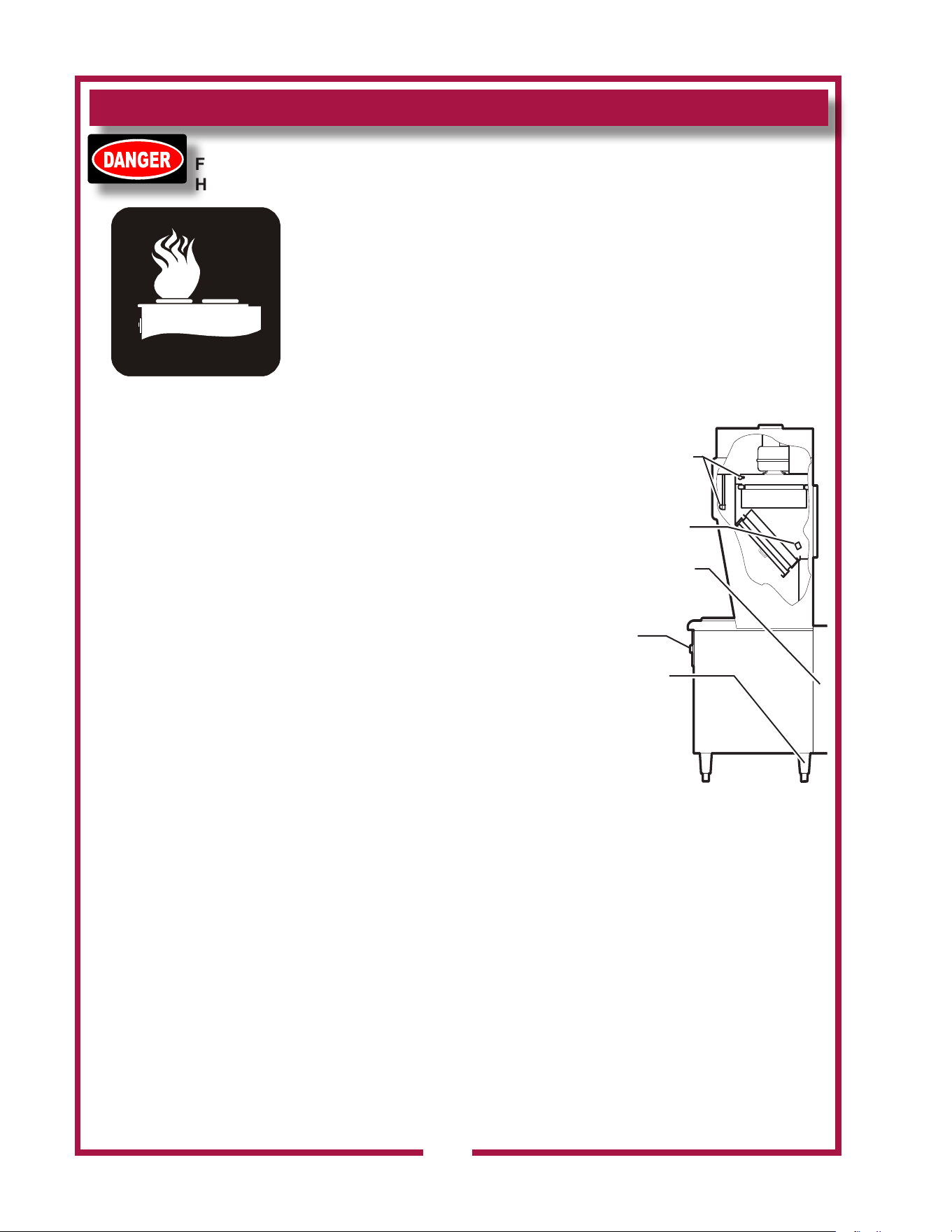
2. The FIRE SUPPRESSION SYSTEM is comprised of a
pressurized cartridge
& container of liquid
re suppressant, with
associated plumbing and
controls. It utilizes factory
installed FUSIBLE LINKS
for automatic actuation,
and a factory installed
MANUAL PULL STATION
for manual actuation.
Two NOZZLES are used
to disperse the liquid re
suppression media.
3. When the re suppression
system activates, the
re suppression media
is discharged, both the
cooking appliance and
the ventilator are de-
energized, and a buzzer
will sound continuously.
The re suppression
media will form an emulsion designed to both smother and cool the
re.
Call your Authorized Ansul® Distributor immediately for service.
NOTE: See page 28 for the Material Safety Data Sheet for the re
suppression agent.
4. The MANUAL PULL STATION and any similar REMOTE MANUAL
PULL STATION will activate the re suppression system when the
ring on the pull station is pulled horizontally.
DANGER
FIRE
HAZARD
THE FIRE SUPPRESSION
SYSTEM MUST BE
CHARGED AND CERTIFIED
BY AN AUTHORIZED
ANSUL® DISTRIBUTOR.
NEVER ATTEMPT TO
MODIFY OR BYPASS
THE FIRE SUPPRESSION
SYSTEM. AN
UNCONTROLLED FIRE CAN
CAUSE SERIOUS INJURY,
DEATH AND/OR PROPERTY
LOSS.
IMPORTANT: The FIRE
SUPPRESSION SYSTEM
must be SET-UP and
CHARGED by an authorized
Ansul® distributor before the
ventilator blower will operate.
NOTE: If the re
suppression system is
discharged, a buzzer will
sound continuously and
the cooking appliance will
remain inoperable until the
re suppression system
is serviced. Recharging
and resetting must be
performed by an authorized
Ansul® distributor ONLY.
Charging of the Ansul
Fire Suppression system
must be in accordance
with Ansul® Design,
Installation, Recharge
and Maintenance Manual.
(Ansul® #418087-05)
FIRE SUPPRESSION
AGENT DISPENSING
NOZZLES (2 PLACES)
ALL MODELS SHIP
WITH 2 FACTORY-
INSTALLED
FUSIBLE LINKS
MANUAL PULL
STATION
LOCATION
REAR CASTERS
REPLACED WITH
LEGS WHEN A
REMOTE MANUAL
PULL STATION
IS INSTALLED
REMOVE REAR PANEL
FOR ACCESS TO FIRE
SUPPRESSION SYSTEM
CONTROLS
IL2146
Fig. 6 Fire Suppression System
10
M506 2M-304964 Owners Manual WVOC-4H
FILTERS INSTALLATION
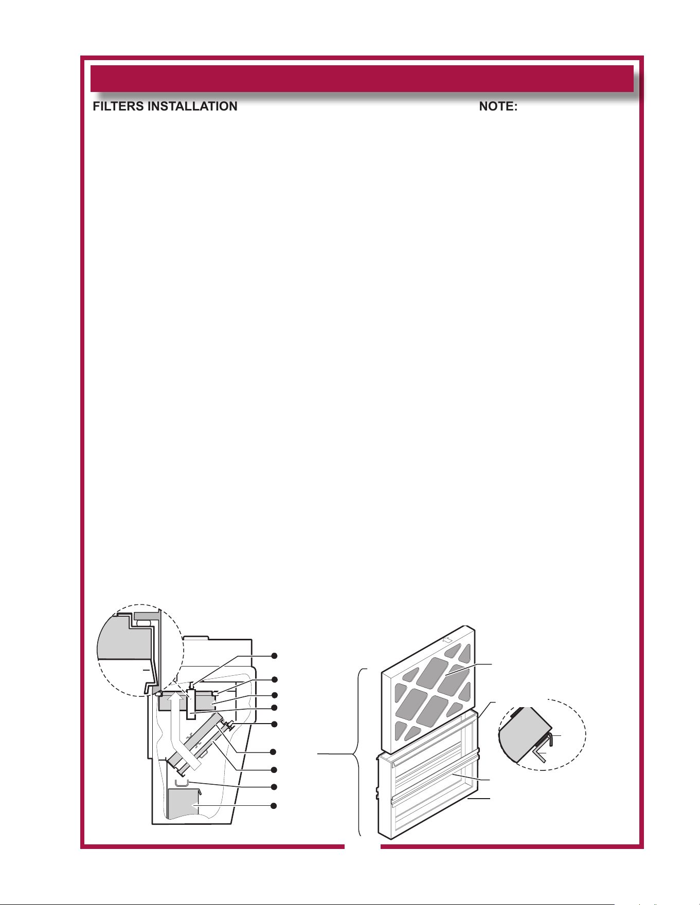
FILTER PACK: Ships installed in the hood. If the FILTER PACK is not
in position, the CHECK FILTERS indicator will light.If the FILTER
PACK becomes clogged, the REPLACE FILTER PACK indicator will
glow.
To install the FILTER PACK: Position the lter pack with the charcoal
portion UP. Slide the lter pack toward the rear of the unit until it
contacts the guides on the back panel. Push the lter pack UP into
the upper opening until it rests rmly against the lter pack seal.
When up in position, holder clips can be snapped over wall ledge on
each side. To remove FILTER PACK: Grasp both holder clips and
pull INWARD until the clips clear the sidewall ledge. Then, pull the
lter pack down and out.
PRE-FILTER: The PRE-FILTER ships in the FILTER FRAME. If the
PRE-FILTER is not in position, or if the PRE-FILTER is not in the
FILTER FRAME, the CHECK FILTERS indicator will light.
If the PRE-FILTER becomes clogged, the REPLACE PRE-FILTER
indicator will glow.
To install the PRE-FILTER: Pay attention to the air ow markings.
The AIR FLOW arrow will point away from the installer. Slide the
assembly up into the front opening, behind the upper lter rail.
While pressing slightly against the bottom of the assembly, pull the
FILTER HANDLE toward you so as to engage the FILTER HOOK
over the lip of the top lter rail. Then lower and seat the assembly
into the top indentation of the lower lter rail.
GREASE BAFFLE: If the GREASE BAFFLE is not in place, the CHECK
FILTERS indicator will glow.
To install the GREASE BAFFLE: Slide the grease bae up into
the indentation of the upper lter rail, then lower and seat it into the
bottom indentation of the lower lter rail. Pull toward you and
downward to verify the GREASE BAFFLE is properly seated in the
lower frame rail.
NOTE:
The GREASE BAFFLE
and FILTER PACK activate
mechanical switches, and
the PRE-FILTER activates
a vacuum switch, to verify
that the lter elements are
in their proper positions.
All lter elements must be
properly installed or the
cooktop will not be
energized. Also, the
CHECK FILTERS indicator
will light.
IMPORTANT:
The lter hook prevents
the PRE-FILTER
from being drawn in
during operation. After
installation, press against
the top of the lter frame to
verify proper engagement
of the lter hook over the
lip of the top lter rail.
Use only genuine Wells
parts and lters, call
(800) 264-7827 or your
authorized Wells service
agent. Parts supplied
by others will void your
warranty and may not
provide safe operation.
INSTALLATION (continued)
FILTER
RAIL
FILTER
HOOK
FILTER PACK
PRE-FILTER
ASSEMBLY
GREASE
BAFFLE
GREASE
TROUGH
GREASE
CUP
AIR FLOW
HOLDER CLIP
FILTER PACK
POSITION
SWITCH
GREASE BAFFLE
POSITION
SWITCH
FILTER PACK
SEAL
PRE-FILTER
NOTE: AIR FLOW ARROW
POINTS FROM
INSTALLER WHEN
PROPERLY INSTALLED
AWAY
FILTER
FRAME
AIR FLOW
NOTE: PRE-FILTER IS SENSED
AS BEING IN POSITION BY THE
PRESSURE DROP ACROSS IT.
FILTER HOOK
FILTER
HANDLE
FILTER PACK
SEAL
HOLDER CLIP
CLIPS ONTO
LEDGE
WALL OF UNIT
PRE-FILTER
IL2147
Fig. 7 Filter Installation
11
M506 2M-304964 Owners Manual WVOC-4H
12
INSTALLATION (continued)
WARNING
SLIP / FALL
HAZARD
SPILLED OIL
DO NOT OPERATE UNLESS
THE GREASE CUP IS
INSTALLED.
Oil and moisture will drip onto
the oor and falls may result.
Death or serious injury may
result from slipping and falling
CAUTION:
BURN HAZARD
DO NOT OPERATE UNLESS
GREASE TROUGH IS
INSTALLED.
Moisture will drip into the hot
cooking surface, causing
splattering of hot liquids.
Serious injury can result from
contact with hot splatter.
GREASE TROUGH AND GREASE CUP INSTALLATION
1. Install the GREASE TROUGH into the brackets below the grease
bae.
2. Install the GREASE CUP on the right side of the unit, directly
below the grease trough.
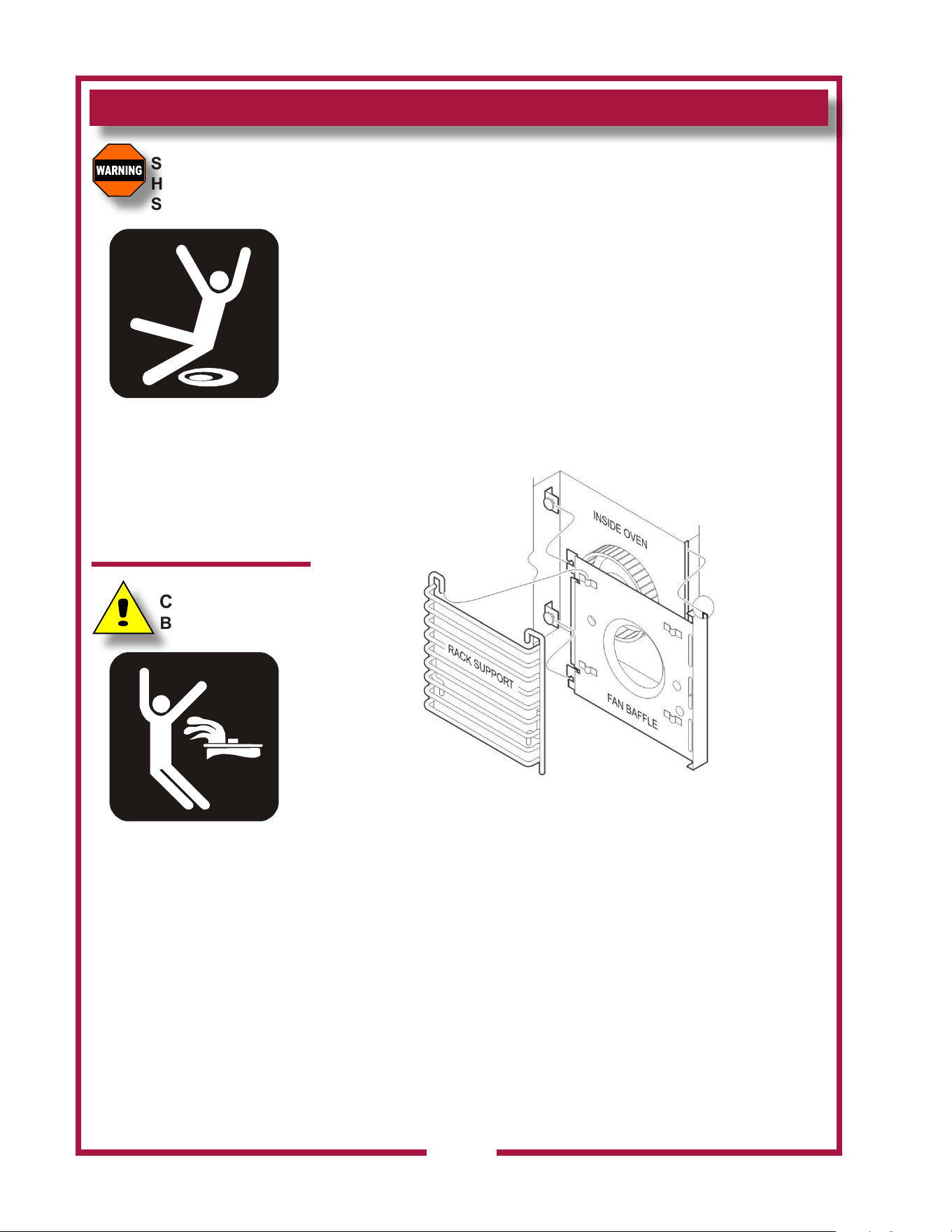
OVEN RACK INSTALLATION
1. Install fan bae. Use care around the fan. The blades are sharp.
2. Install one rack support on the fan bae, and one rack support on
the left wall of the oven cavity.
3. Install racks as needed for the product being prepared.
Fig. 8 Oven Rack Installation
M506 2M-304964 Owners Manual WVOC-4H
OPERATION
13
CAUTION:
HOT SURFACE
Exposed surfaces can be hot
to the touch and may cause
burns.
VENTILATOR OPERATION
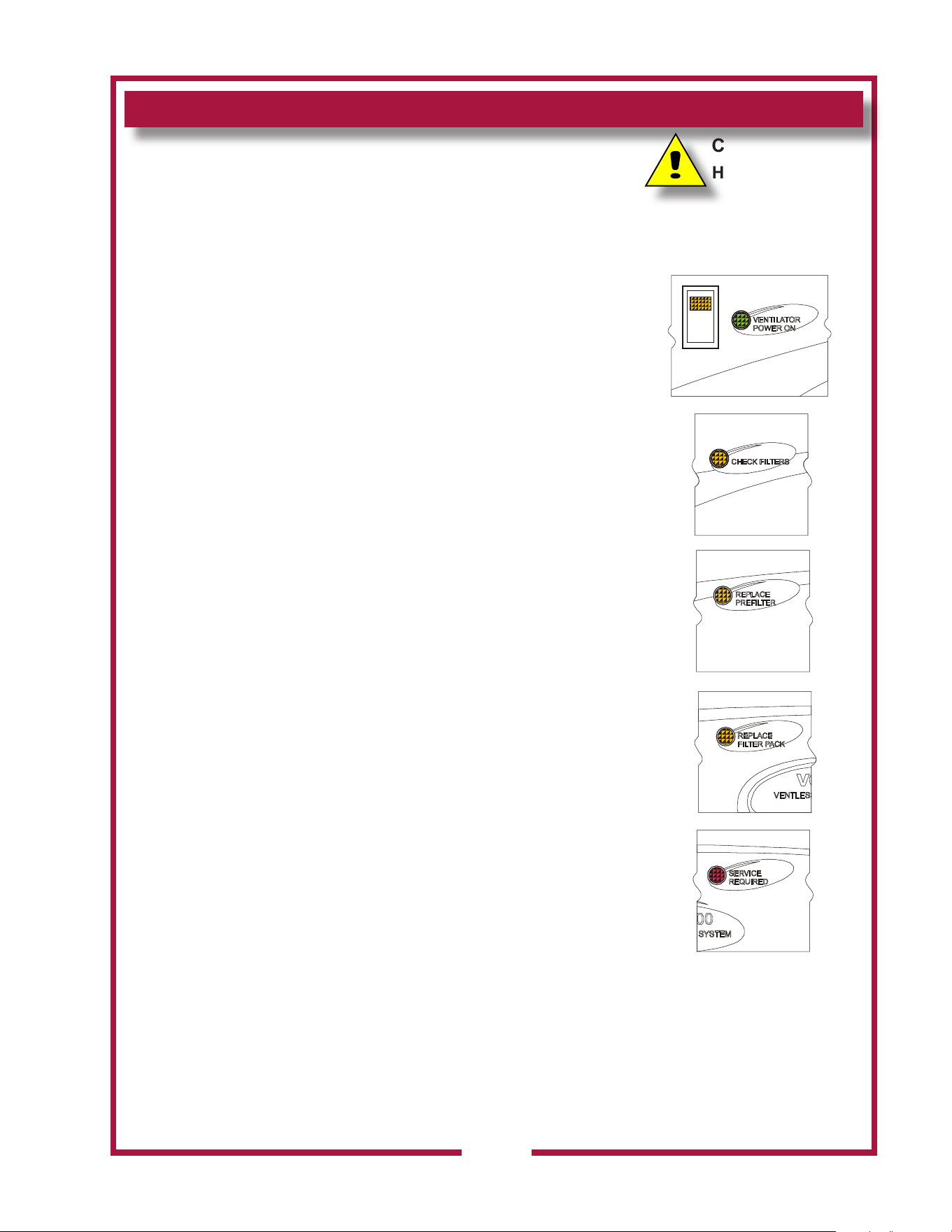
1. Press the VENTILATOR POWER switch to ON. The green
VENTILATOR POWER light will glow and the blower fan will start.
After a short time, if all lters are sensed as being in position and
not clogged, the cooking appliance will be energized. The roll
warmer is energized at all times.
During normal operation, the VENTILATOR POWER light will be
the only light glowing on the upper control panel.
2. If the amber CHECK FILTER light glows, one or more lter elements is
out of position. Check the GREASE BAFFLE,
PRE-FILTER and FILTER PACK for proper installation in their
respective positions. Grease bae and lter pack position are sensed
by mechanical switches. Pre-lter position is sensed by a
vacuum switch.
3. When the amber REPLACE PRE-FILTER light glows, the pre-lter
is nearing the end of its service life. Replace the disposable PRE-
FILTER ELEMENT.
4. When the amber REPLACE FILTER PACK light illuminates, the
HEPA / Charcoal lter pack is nearing the end of its service life.
Replace the lter pack.
Note: The REPLACE PRE-FILTER and REPLACE FILTER PACK
lights are a warning that the indicated lter is near the end of its
service life. The appliance will continue to operate for a period of
time after the light glows to allow continued operation through a
peak period. However, the indicated lters must be replaced within
a reasonably short time period or they will clog and shut down
electrical power to the cooking appliance . The ventilator blower
will continue to run.
5. When the red SERVICE REQUIRED light glows, either the
pre-lter or lter pack (or both) is clogged and can no longer pass
sucient air to allow further operation. The ventilator fan continues
to run, but the cooking appliance is shut down until the underlying
clogged lter situation has been corrected. This can occur when
neither CHANGE...FILTER indicator light is lit, if both pre-lter and lter
pack are marginal. Replacing both the pre-lter and the lter pack
will remedy the situation.
NOTE: Replacing the pre-lter, even though not very dirty, will often
extend the service life of the more expensive lter pack.
Reset the unit by turning the VENTILATOR POWER switch to OFF,
then back ON.
6. A failure of incoming electrical power will cause a shut down of
the unit. After power is restored, reset the unit by turning the
VENTILATOR POWER switch to OFF, then back ON.
NOTE: Oven, griddle and hotplate will not operate unless the re
suppression system is charged, and the ventilator section is operating
Fig. 9 Ventilator Indicator
and Warning Lights
M506 2M-304964 Owners Manual WVOC-4H

OPERATION (continued)
14
SUGGESTED COOKING TIMES
A. CONVECTION OVEN
PRODUCT TEMP TIME NUMBER
ºF MINUTES OF RACKS
BREAD PRODUCTS
Hamburger Roll 300 15 5
Bread (1 lb loaves) 325 34 3 (12 loaves)
Roll 300 16 5 (60 rolls)
Baking Soda Biscuit 400 7 3
For best baking results, use rack positions 2, 5 & 8 ( where rack position 1 is the top rack)
Baking one pan: use rack 5; baking 2 pans: use racks 2 & 8.
PASTRIES
Sheet Cake (2½ lbs. per pan) 300 17 5
Frozen Fruit Pie (46oz.) 350 50 5 (10 pies)
Frozen Fruit Pie (26oz. - 8” dia.) 350 40 5 (15 pies)
Sugar Cookie 300 15 5
Danish Roll 350 12 5
Fruit Cake 275 75 3
Cake (1 lb.) 300 19 5 (10 cakes)
OTHER
Melted Cheese Sandwich 400 8 5
Idaho Potato (120 potatoes) 450 40 5
Macaroni & Cheese 350 30 5
NOTE: “HIGH” fan speed provides the fastest cook time. “LOW” fan speed is used for foods which are
sensitive to air currents, such as meringue pie.
M506 2M-304964 Owners Manual WVOC-4H
OPERATION (continued)
15
CONVECTION OVEN OPERATING INSTRUCTIONS
A. MANUAL COOK MODE
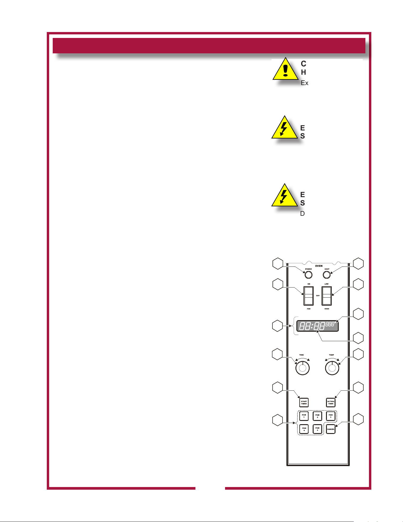
1. Set the OVEN POWER SWITCH (C.01) to ON. The OVEN
POWER ON INDICATOR (C.03) will glow when the switch is ON.
2. Rotate OVEN TEMPERATURE CONTROL knob (C.07) until the
desired cooking temperature is displayed on the READOUT
(C.05A). The oven will begin heating, and the temperature digits
will ash, until the set temperature is reached.
3. Rotate OVEN TIME CONTROL knob (C.06) until the desired time
is displayed on the READOUT. The digits and colon will ash,
indicating that time has been set but the timer is not started.
4. Load product in the oven. Press START TIMER key (C.08).
The timer digits count down and the colon (only) ashes during the
timer period.
5. At the end of the timer period, an audible alarm will sound.
Press CANCEL key (C.11) to silence the alarm.
SUGGESTION: For best baking results when making baking soda
biscuits, use rack positions 2, 5 & 8 ( where rack position 1 is the top
rack). When baking one pan: use rack 5 (center rack); when baking
2 pans: use racks 2 & 8; when baking three pans: use racks 2, 5 & 8.
B. PROGRAM COOK MODE
1. Five (5) programmable keys (C.10) are provided for presetting
frequently used time / temperature combinations. To set the
program:
a. Press and hold the appropriate PGM key.
b. While holding the PGM key, turn the TIME and TEMP knobs
until the desired time and temperature is displayed on the
readout.
c. Release the PGM key to store the displayed time and temp in
memory.
2. The program for any PGM key can be recalled by momentarily
pressing that PGM key.
3. To start a programmed cook cycle, press the appropriate PGM key
and the START TIME key. Once the cook cycle has started, the
TIME and TEMP knobs are locked out to prevent accidental re-
programming.
4. The actual oven temperature may be recalled at any time by
pressing the ACTUAL TEMP key (C.09).
5. At the end of the timer period, an audible alarm will sound.
Press CANCEL key (C.11) to silence the alarm.
CAUTION:
HOT SURFACE
Exposed surfaces
can be hot to the touch and
may cause burns.
CAUTION:
ELECTRIC
SHOCK HAZARD
DO NOT splash or pour water
onto control panel or wiring.
CAUTION:
ELECTRIC
SHOCK HAZARD
DO NOT operate the
unit if the keypad is torn or
broken.
C.01 C.02
C.03
C.04
C.05
C.06
C.07
C.08 C.09
C.10
C.11
C.05
A
C.05
B
M506 2M-304964 Owners Manual WVOC-4H
OPERATION (continued)
16
C. TEMPERATURE OFFSET MODE
1. A user preference oset mode is provided should the user feel the
oven cooks too hot or too cold.
2. The OFFSET MODE can be used to oset the set / displayed
temperature from the sensed temperature by as much as ± 35ºF, in
5ºF increments:
a. Rotate the TIME controller until the time digits on the display
read “00:00”.
b. Rotate the TEMP control until the temp digits display between
400º and 500º.
c. Press and hold the START TIMER key for ve seconds.
d. Turn either the TIME or TEMP control until the desired oset is
displayed.
e. Press the ACTUAL TEMP key to exit.
CAUTION:
HOT SURFACE
Exposed surfaces can be hot
to the touch and may cause
burns.
CAUTION:
BURN HAZARD
Do not attempt to clean
the oven until it has cooled
to 150ºF or less. See
CLEANING INSTRUCTIONS,
page 18.
CAUTION:
ELECTRIC
SHOCK HAZARD
DO NOT splash or pour water
onto control panel or wiring.
IMPORTANT:
To extend the life of your
appliance and internal
components, allow the oven,
and hotplates to cool to 200ºF
or less before turning the
ventilator o.
M506 2M-304964 Owners Manual WVOC-4H
OPERATION (continued)
17
CAUTION:
HOT SURFACE
Exposed surfaces can be hot
to the touch and may cause
burns.
CAUTION:
ELECTRIC
SHOCK HAZARD
DO NOT splash or pour water
onto control panel or wiring.
CAUTION:
ELECTRIC
SHOCK HAZARD
Use extreme caution when
using double broiler-type
pans: DO NOT over ll the
lower pan with water, which
can cause an overow. Any
moisture splashed onto the
hotplate top can leak into
the lower areas of the oven
causing a potential shock
hazard and causing severe
damage to the electronic
controller.
NOTE: Damage caused
by moisture leaking into the
electronic controller is NOT
covered by warranty.
IMPORTANT:
The dial markings are an
INDICATION of temperature
only. The temperature of
the food product depends on
many factors, including the
size, shape and material of
the food container, and the
quantity and consistency of
the food product.
HOTPLATE OPERATING INSTRUCTIONS
A. COOKING WITH YOUR HOTPLATE
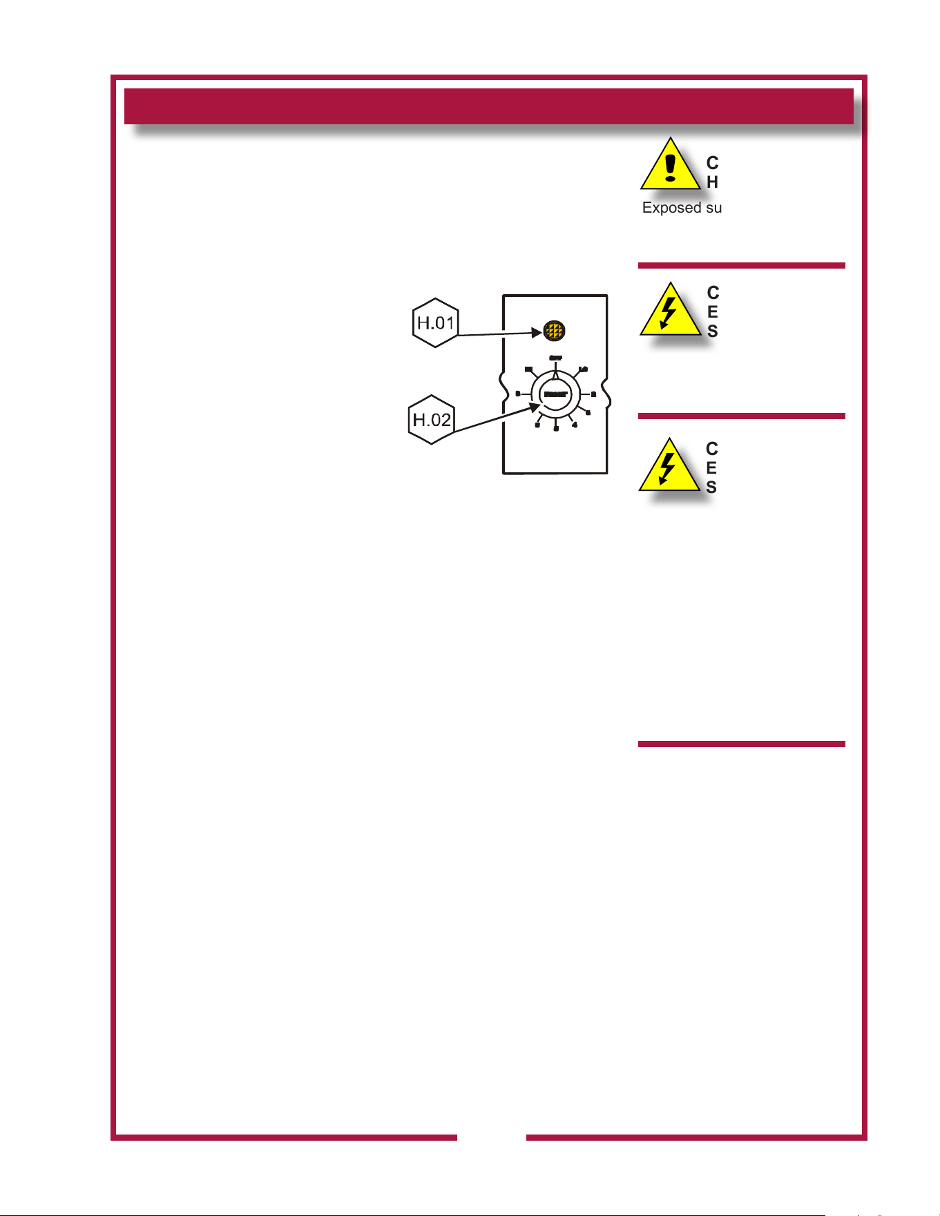
1. Each element is individually controlled by a TEMPERATURE
CONTROL (H.01 and H.03). These are innite switch controls
which control based on electrical
current draw, not the actual
temperature of the hotplate
surface.
2. Settings are OFF to HIGH.
3. The associated indicator will
glow when the switch is in any
position other than OFF.
4. When set to HIGH, the hotplate
element can reach maximum
temperature in approximately 10
minutes.
5. Once liquid begins to boil, reduce the setting to minimize power
consumption and increase the useful life of the elements.
6. Use cooking pans which fully cover the elements for maximum
eciency. Maximum recommended pot diameter is 10 inches.
M506 2M-304964 Owners Manual WVOC-4H
18
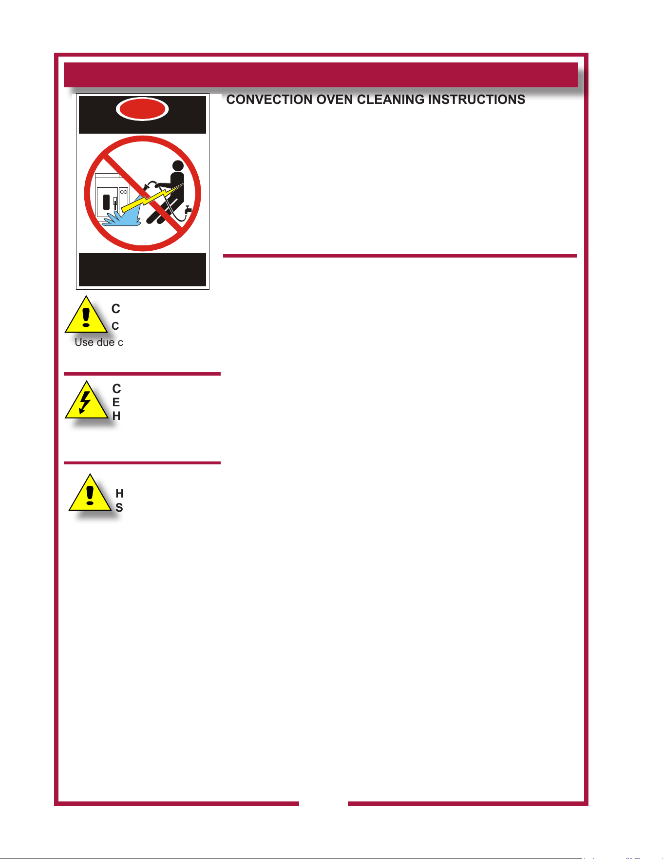
CONVECTION OVEN CLEANING INSTRUCTIONS
PRECAUTIONS Turn oven power switch to FAN
Allow oven to cool
FREQUENCY As Noted
TOOLS Mild Detergent, Soft Cloth or Sponge
Plastic Scouring Pad
Spray Bottle
Commercial Oven Cleaner/Degreaser
DAILY
1. Turn oven power switch to FAN; remove racks and take to back
sink.
2. Let oven cool to 200°F. If oven is cooler than 200°F, raise
temperature to no more than 200°F.
3. Mix oven cleaner/degreaser per manufacturer’s directions. Spray
oven cleaner/degreaser solution onto soiled surfaces; then, close
oven door and let stand for 5 min.
4. Open door slowly to allow steam to escape and allow oven to cool
completely.
5. Wipe oven surfaces with a soft cloth, rinse cloth as necessary.
6. Re-spray any remaining soiled areas and scrub with a plastic
scouring pad.
7. Rinse all surfaces with a clean soft damp cloth.
8. Wash, rinse, and sanitize oven racks and replace in oven.
9. Wipe exterior surfaces with a clean cloth dampened with clean
water and a non-abrasive cleanser. Rinse by wiping with a clean
cloth dampened with clean water.
HEAVY SOIL RECOVERY—As Needed
1. Turn oven power switch to FAN; remove racks and take to back
sink.
2. Let oven cool to 200°F. If oven is cooler than 200°F, raise
temperature to no more that 200°F.
3. Spray Oven Cleaner/Degreaser full strength onto soiled surfaces;
then, close oven door and let stand for 5 min.
4. Open door slowly to allow steam to escape and allow oven to cool
completely.
5. Wipe oven surfaces with a soft cloth, rinse cloth as necessary.
6. Re-spray any remaining soiled areas and scrub with a plastic
scouring pad.
7. Rinse all surfaces with a clean soft damp cloth.
8. Wash, rinse, and sanitize oven racks and replace in oven.
CLEANING INSTRUCTIONS
CAUTION:
CUT HAZARD
Use due care when cleaning
near fan. Blades are sharp.
CAUTION:
ELECTRIC SHOCK
HAZARD
DO NOT splash or pour water
onto control panel or wiring.
CAUTION:
HEAT AND
SMOKE HAZARD
Keep the ventilator fan
running during any “hot
surface” cleaning operation
to avoid a build-up of heat
and/or smoke.
IMPORTANT: Avoid Fire
Suppression System
discharge!
Keep the ventilator fan
running during any “hot
surface” cleaning operation
to avoid melting a fusible link
and causing a discharge of
the re suppression media.
IMPORTANT:
Always rub / wipe in the
direction of the polish lines
or grain of the metal.
DANGER
ELECTRIC SHOCK HAZARD
DO NOT SPRAY WATER ON OR AROUND
ELECTRICAL EQUIPMENT
DO NOT WASH FLOOR NEAR ELECTRICAL
EQUIPMENT WITH WATER SPRAY
M506 2M-304964 Owners Manual WVOC-4H
19
HOTPLATE CLEANING INSTRUCTIONS
PRECAUTIONS Turn oven controls to OFF
Allow hotplates to cool
FREQUENCY Daily
TOOLS Mild Detergent, Soft Cloth or Sponge
Non-abrasive Cleaner, Plastic Scouring Pad
1. Turn both controls to OFF. Allow both hotplate elements to cool.
2. Wipe the entire hotplate top panel using a clean cloth or sponge,
dampened with hot water and a mild detergent. For burned-on
foods or sauce spillage, use a non-abrasive cleanser applied with
a plastic scouring pad.
3. Rinse hotplates and top panel with a soft cloth dampened with clean
water.
CLEANING INSTRUCTIONS (continued)
CAUTION:
BURN HAZARD
Turn o both hotplates and
allow to cool before cleaning
CAUTION:
ELECTRIC
SHOCK HAZARD
DO NOT splash
or pour water onto warmer,
control panel or wiring.
CAUTION:
HEAT AND
SMOKE HAZARD
Keep the ventilator fan
running during any “hot
surface” cleaning operation
to avoid a build-up of heat
and/or smoke.
IMPORTANT: Avoid Fire
Suppression System
discharge!
Keep the ventilator fan
running during any “hot
surface” cleaning operation
to avoid melting a fusible link
and causing a discharge of
the re suppression media.
IMPORTANT:
This appliance is not jet
stream approved. Do not
direct water jet or steam jet
at this appliance, or at any
control panel or wiring.
Do not splash or pour
water on, in or over any
controls, control panel or
wiring.
IMPORTANT:
Always wipe or rub in the
direction of the polish lines or
grain of the metal.
M506 2M-304964 Owners Manual WVOC-4H
CLEANING INSTRUCTIONS (continued)
VENTILATOR SECTION CLEANING INSTRUCTIONS
PREPARATION
Disconnect appliance from electric power
Allow to cool before cleaning
FREQUENCY Weekly
TOOLS
Warm water and a mild detergent
Soft clean cloth or sponge
Bristle brush
Container for disposal of grease
CLEANING
1. Disconnect appliance from electric power
2. Allow to cool before cleaning
3. Remove the grease bae, pre-lter assembly, grease trough and
grease cup. Empty the grease trough and grease cup.
4. Remove the pre-lter from the lter frame. Wash and rinse the
lter frame ONLY.
5. Wash and rinse the grease bae, grease trough and grease cup in
a sink or dishwasher using mild detergent and warm water. Allow
to air dry.
6. Reinsert the pre-lter into the lter frame. Reinstall the pre-lter,
grease bae, grease trough and grease cup.
Procedure is complete
CAUTION:
ELECTRIC
SHOCK HAZARD
Disconnect appliance
from electric power before
cleaning.
CAUTION:
HOT SURFACE
Exposed surfaces can be hot
to the touch and may cause
burns. Allow appliance to cool
before cleaning.
IMPORTANT:
Never allow PRE-FILTER or
FILTER PACK to get wet.
DO NOT wash either of these
two lters. Washing these
lters will ruin them and cause
the appliance to shut-down.
IMPORTANT:
DO NOT spill or pour water
into controls, control panel,
wiring or coil-type hotplate
elements. Damage to internal
components will occur.
Damage to internal
components from water
damage is not covered by
warranty.
IMPORTANT:
DO NOT use steel wool or
metal implements to clean
drawers or cabinet surfaces.
20
M506 2M-304964 Owners Manual WVOC-4H

21
TROUBLESHOOTING SUGGESTIONS
A. NO PART OF THE APPLIANCE WILL HEAT
1. Verify that appropriate cooking controls are ON.
2. Check electrical supply. Make sure service breaker is ON.
3. Make sure all lters are properly installed, and that no lter warning
lights are lit.
4. Possible improper service wiring: Have a licensed electrician verify
that all three legs of the 3ø service are properly connected
(i.e. Leg 1 to L1, Leg 2 to L2, Leg 3 to L3), and that all three legs are
of the proper voltage and phase.
5. Ansul® Fire Suppression System not charged.
B. HOTPLATE WILL NOT HEAT
1. Verify that associated temperature control is set to the desired
temperature.
2. Possible internal component damage: Have unit serviced by an
Authorized Wells Service Agency.
C. CONVECTION OVEN WILL NOT HEAT
See Error Codes diagram at right
1. Verify that the oven switch is ON and that the temperature control is
set to the desired temperature.
2. Verify that the door is closed.
3. Hi-Limit control may have tripped: Allow unit to cool; Hi-Limit will
reset automatically.
4. Blown fuse(s) (item 40): Correct cause of over-current and replace
fuses with fuses having the same conguration and ratings.
5. Possible internal component damage: Have unit serviced by an
Authorized Wells Service Agency.
D. CONVECTION OVEN FAN WILL NOT RUN
1. Verify that the oven switch is set to ON or FAN.
2. Verify that the fan switch is set to either HIGH or LOW.
3. Hi-Limit control may have tripped: Allow unit to cool; Hi-Limit will
reset automatically.
4. Blown fuse(s): Correct cause of over-current and replace fuses with
fuses having the same conguration and ratings.
5. Possible internal component damage: Have unit serviced by an
Authorized Wells Service Agency.
CAUTION:
ELECTRIC
SHOCK HAZARD
Removal of any cabinet
panel will result in exposed
electrical circuits. Any
procedure requiring the
removal of any cabinet panel
must be performed by a
qualied technician only.
CONVECTION OVEN
CONTROLLER
ERROR CODES
F1 Relay closed or relay
ohms low when not
cooking
F2 Actual temperature 60ºF
(±35ºF) greater than T-
SET MAX
F3 Open temperature sensor
F4 Shorted temperature
sensor
F5 Relay open or relay ohms
high when cooking
F6 No 60 Hz (Cycles per
second other than 60 Hz
detected)
Have unit serviced by an
Authorized Wells Service
Agency.
NOTE: Other than the
ventilator lters, there are no
user serviceable components
in the appliance. In all cases
of damage or component
malfunction, contact your
Authorized Wells Service
Agency for repairs.
M506 2M-304964 Owners Manual WVOC-4H
22
MAINTENANCE INSTRUCTIONS
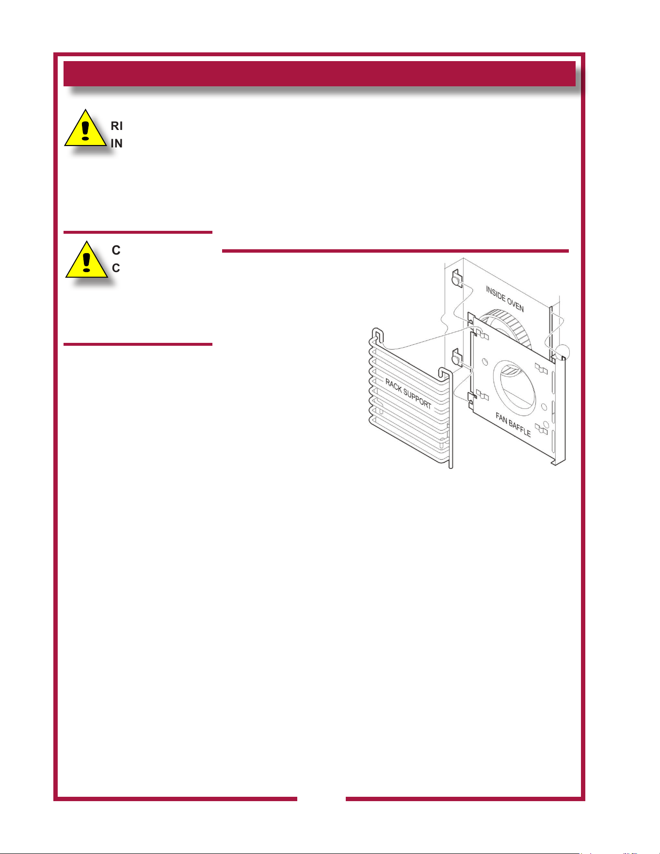
FAN CLEANING
PRECAUTIONS: Disconnect power at the circuit breaker.
Allow the oven to cool.
FREQUENCY: Monthly, at a Minimum; or, As Needed
TOOLS: Moist Cloth or Spongs
Bristle Brush
1. Disconnect power at the
circuit breaker. Allow the
oven to cool.
2. Remove RACKS by
pulling toward the front.
Lift to clear the stop pin.
Remove left and right
RACK SUPPORTS by
lifting.
3. Remove BAFFLE by
lifting the rear slightly
and pulling straight out.
4. Brush fan wheel and
wipe it with a moist cloth. Sponge out all loose particles.
5. Reassemble, paying particular attention that the lip on the right
side of the fan bae is fully seated in the slot in the edge of the
oven cavity.
CAUTION:
RISK OF
INJURY
Disconnect appliance from
electrical power before
performing any of these
procedures.
CAUTION:
CUT HAZARD
Use due care when
cleaning fan. Blades are
sharp.
M506 2M-304964 Owners Manual WVOC-4H
MAINTENANCE INSTRUCTIONS (continued)
23
CAUTION:
BURN HAZARD
Allow appliance to cool
completely before adjusting.
Hinge Adjustment
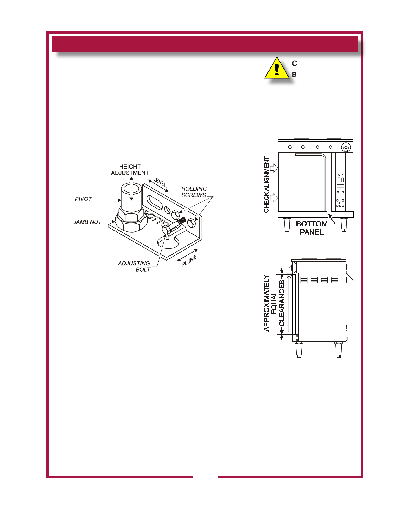
HINGE ADJUSTMENT
PRECAUTIONS: None
FREQUENCY: Monthly, at a Minimum; or, As Needed
TOOLS: Phillips (+) Screwdriver
7/16” Nut Driver
7/8” and 1-1/8” Wrenches
THE FOLLOWING PROCEDURE IS TO BE PERFORMED
BY QUALIFIED PERSONNEL ONLY
1. Remove bottom panel to access pivot.
2. Gap between top of door and frame , and between bottom of door
and frame must be approximately equal
Adjust height of door by loosening jamb nut, then turning
pivot on its screw mounting. Clockwise lowers the door
height. Re-tighten jamb nut .
3. Gap between left side of door and frame must be the
same from top to bottom
Adjust door for plumb by loosening holding screws. Turn
adjusting bolt to increase or decrease gap at bottom.
Clockwise increases gap. Re-tighten holding screws.
4. Gap between top of door and frame must be the same
from side to side
Adjust door for level by loosening holding screws, then
raising or lowering latch-end of door until it is level.
Re-tighten holding screws.
5. Reinstall bottom panel.
Procedure is complete
M506 2M-304964 Owners Manual WVOC-4H
MAINTENANCE INSTRUCTIONS (continued)
D. TEMPERATURE CALIBRATION
TOOLS: Digital Pyrometer with Oven Probe, Protective Gloves
1. With the oven empty, clamp the thermocouple sensor in the center
of the middle rack:
a. Pass the thermocouple sensor wires through the corner of the
door gasket and close the door.
b. Plug the sensor into the Pyrometer.
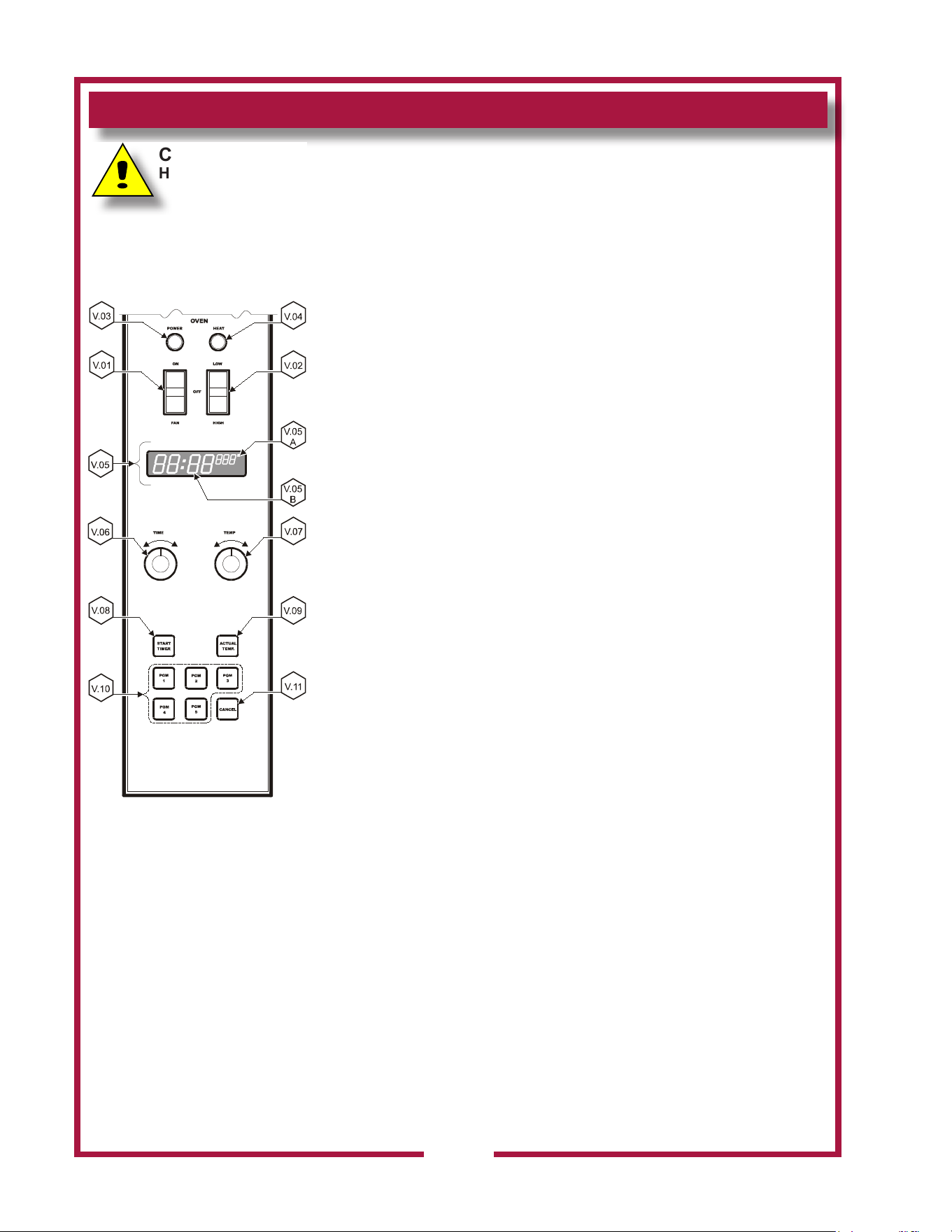
2. Turn the OVEN POWER (V.01) switch to ON. Turn the FAN
switch (V.02) to HI.
a. Rotate the TIME control (V.06) until the time digits (V.05B) on
the display read “60:00”.
b. Rotate the TEMP control (V.07) until the temp digits (V.05A)
display 375º.
c. Press the START TIMER key (V.08).
3. Allow the oven to heat for 45 minutes. If, after 45 minutes, the
temperature display reads between 370º and 380º, the calibration
is satisfactory. Otherwise:
a. Rotate the TIME controller until the time digits (V.05B) on the
display read “00:00”.
b. Rotate the TEMP control until the temp digits (V.05A) display
between 400º and 500º.
c. Press and hold the START TIMER (V.08) key for ve seconds.
d. Turn either the TIME or TEMP control until the desired oset is
displayed.
e. Press the ACTUAL TEMP (V.09) key to exit. Procedure is
complete.
CAUTION:
Hot Surface
Exposed surfaces can be hot
to the touch and may cause
burns.
24
M506 2M-304964 Owners Manual WVOC-4H
MAINTENANCE SCHEDULES
USE AND MAINTENANCE
SHALL BE IN ACCORDANCE
WITH THE STANDARD FOR
VENTILATION CONTROL
AND FIRE PROTECTION OF
COMMERCIAL COOKING
OPERATIONS, N.F.P.A 17A &
N.F.P.A. 96 (current editions).
DANGER
FIRE
HAZARD
FAILURE TO PROPERLY
CLEAN AND MAINTAIN THIS
EQUIPMENT CAN
CAUSE A FIRE. AN
UNCONTROLLED FIRE CAN
CAUSE SERIOUS INJURY,
DEATH AND/OR PROPERTY
LOSS.
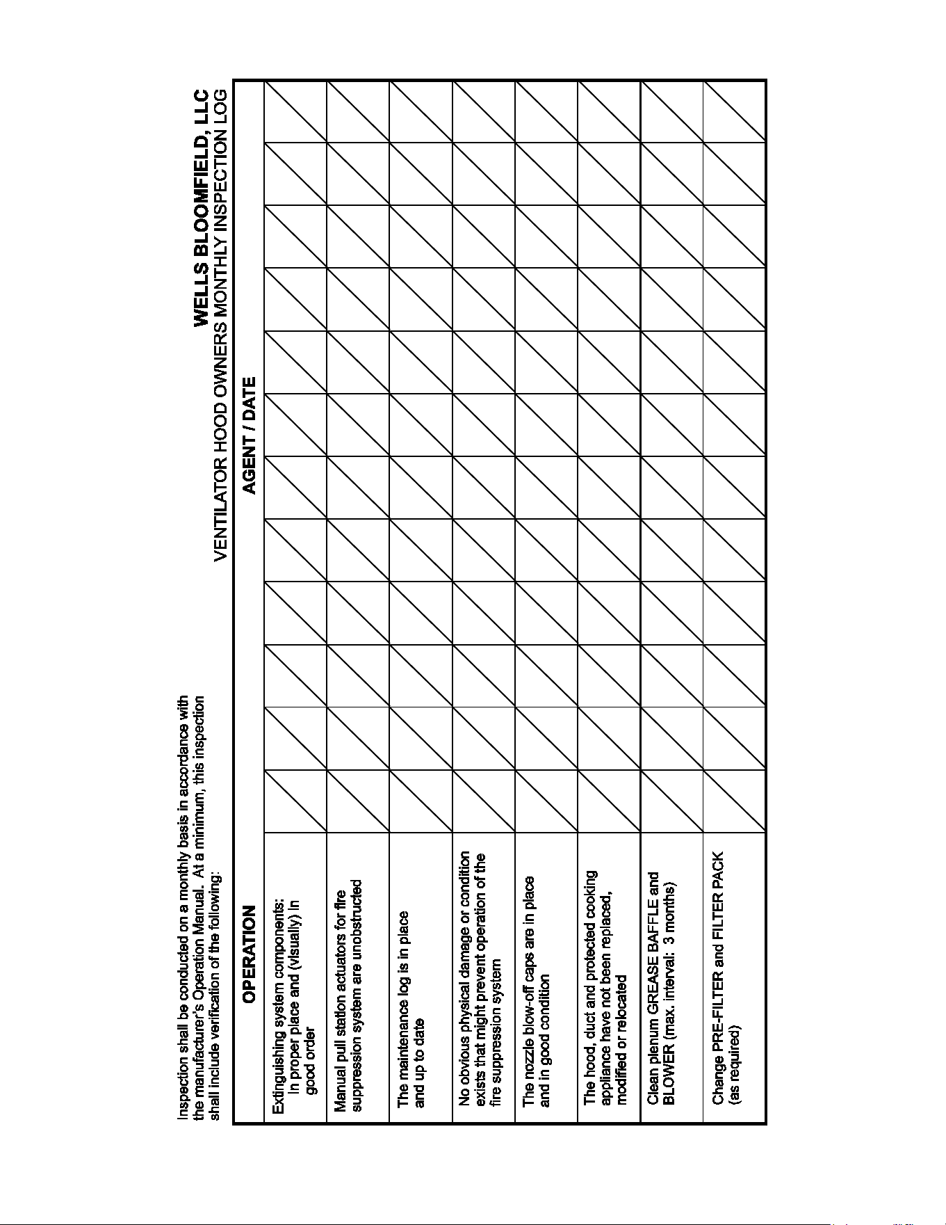
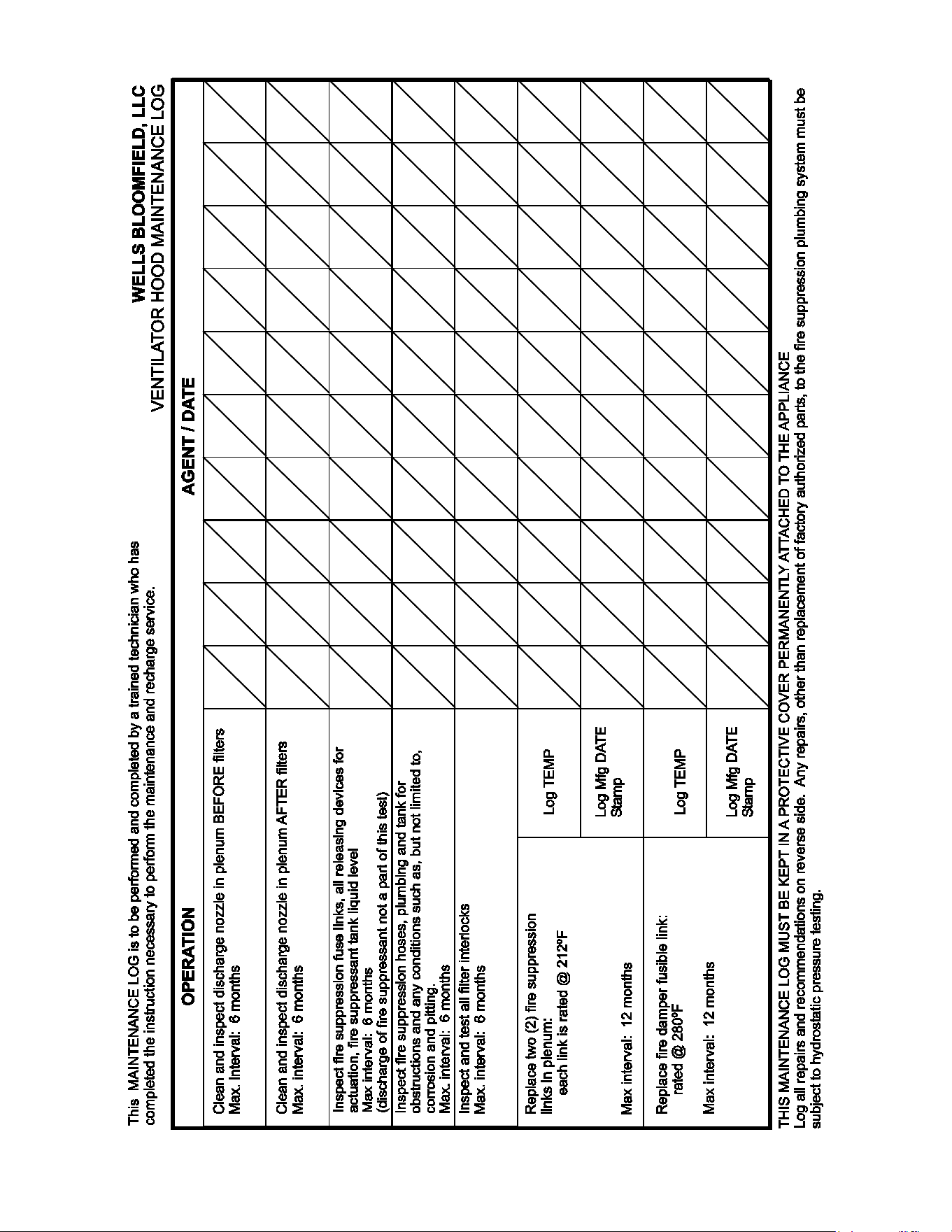
NOTE: A signed and dated
VENTILATOR HOOD
MAINTENANCE LOG must be
maintained on the premises,
and shall be available for
inspection by the authority
having jurisdiction. See pages
26 & 27.
IMPORTANT: Parts
used for the Ansul® re
suppression system are not
serviceable by the owner
/ operator. Procedures for
servicing re suppression
equipment are described in:
ANSUL® R-102 SYSTEM
DESIGN, INSTALLATION,
RECHARGE AND
MAINTENANCE MANUAL
(Ansul® #418087-05).
1. 6-MONTH MAINTENANCE (MUST BE PERFORMED BY AN
AUTHORIZED ANSUL® DISTRIBUTOR ONLY):
a. Inspect and test total operation including FIRE DAMPER and
all SAFETY INTERLOCKS.
b. All FIRE SUPPRESSION SYSTEM actuation components
including MANUAL PULL STATION and any REMOTE
MANUAL PULL STATION must be inspected for proper
operation in accordance with the maintenance schedule
published in ANSUL® R-102 SYSTEM DESIGN,
INSTALLATION, RECHARGE AND MAINTENANCE MANUAL
(Ansul® #418087-05).
c. The FIRE SUPPRESSION SYSTEM FUSIBLE LINKS must be
inspected. NOZZLES and MANUAL PULL STATION must be
cleaned in accordance with ANSUL® R-102 SYSTEM
DESIGN, INSTALLATION, RECHARGE AND MAINTENANCE
MANUAL (Ansul® #418087-05).
d. The FIRE SUPPRESSION AGENT TANK, PIPING and
FLEXIBLE TUBING must be INSPECTED.
2. 12-YEAR MAINTENANCE: (MUST BE PERFORMED BY AN
AUTHORIZED ANSUL® DISTRIBUTOR ONLY):
a. The FIRE SUPPRESSION AGENT TANK and ¼” FLEX HOSE
must be HYDROSTATICALLY TESTED, and the FIRE
EXTINGUISHING AGENT must be REPLACED in accordance
with the maintenance schedule published in ANSUL® R-102
SYSTEM (STANDARD UL 300 LISTED).
b. The FUSIBLE LINKS in plenum and damper must be
REPLACED. This maintenance to be performed by qualied
Ansul® service personnel only.
25
M506 2M-304964 Owners Manual WVOC-4H
26
M506 2M-304964 Owners Manual WVOC-4H
27
M506 2M-304964 Owners Manual WVOC-4H
28
ANSUL
®
ANSUL INCORPORATED
MARINETTE, WI 54143-2542
MATERIAL SAFETY DATA SHEET
ANSULEX Low pH
QUICK IDENTIFIER (In Plant Common Name)
Manufacturer’s
Name:
Emergency
Telephone No.:
ANSUL INCORPORATED
CHEMTREC
(800) 424-9300 or (703) 527-3887
Prepared By:
Address:
One Stanton Street, Marinette, WI 54143-2542
Safety and Health Department
Other Information
Calls:
(715) 735-7411
Date Prepared:
February 1, 1999
SECTION 1 - IDENTITY
SECTION 2 - INGREDIENTS
SECTION 3 - PHYSICAL AND CHEMICAL CHARACTERISTICS (Fire and Explosion Data)
SECTION 4 - PHYSICAL HAZARDS
Common Name (Used on Label):
(Trade Name and Synonyms)
ANSULEX Low pH Liquid Fire Suppressant
CAS No.:
N/A
N/A N/A N/A N/A
N/A
N/A
N/A
N/A
N/A N/A
N/E
N/E
N/E
N/E
N/E
NDA
NDA
NDA
NDA
N/A
Chemical
Name:
N/A This is a Mixture
Chemical
Family:
Mixture
Formula:
PART A - HAZARDOUS INGREDIENTS
PART B - OTHER INGREDIENTS
Principal Hazardous Component(s) (chemical and common name(s)):
Other Component(s) (chemical and common name(s)):
Wt.%
Wt.%
CAS No.
CAS No.
ACGIH TLV
ACGIH TLV
Acute Toxicity Data
Acute Toxicity Data
None
Proprietary Mixture of Organic and Inorganic Salts
48.0 - 50.0
Phosphoric Acid 0.2
7664-38-2
Yellow-Green Fluorescent Dye 0.011
518-47-8
Oral LD (rat)
50
6800 mg/kg
EDTA
0.65
64--02-8
Water
Approx. 50.0
7732-18-5
Boiling
Point:
Percent Volatile
by Volume (%):
Solubility
in Water:
Appearance
and Odor:
Flash Point:
Special Fire
Fighting Procedures:
Unusual Fire and
Explosion Hazards:
113ºC
Approx. 50.0
100%
Fluorescent Yellow Colored Liquid, Mild Odor
None to boiling
NONE - THIS IS AN EXTINGUISHING AGENT
None
Vapor Density:
(Air = 1):
Flammable Limits
in Air % by Volume:
1.03
Specific
Gravity (H O=1):
2
Vapor Pressure
(mm Hg):
1.33
Not Determined
Evaporation Rate:
(Butyl Acetate=1):
Approx. 0.005
Reactivity in
Water:
Mild exothermic reaction
Extinguisher
Media:
Auto-Ignition
Temperature:
Stability:
Incompatibility
(Materials to Avoid):
Hazardous
Decomposition Products:
Hazardous
Polymerization:
Unstable
Stable
Conditions
to Avoid:
Conditions
to Avoid:
Reactive Metals, ClF , electrically energized equipment, any material reactive with water.
3
Not established, acrid fumes.
May Occur
Will Not Occur
M506 2M-304964 Owners Manual WVOC-4H
29
SECTION 5 - HEALTH HAZARDS
SECTION 6 - EMERGENCY AND FIRST AID PROCEDURES
SECTION 7 - SPECIAL PROTECTION INFORMATION
SECTION 8 - SPECIAL PRECAUTIONS AND SPILL/LEAK PROCEDURES
HAZARDOUS MATERIAL IDENTIFICATION SYSTEM
ANSULEX Low pH (continued)
Threshold
Limit Value:
None Established
Routes of Entry:
Eye Contact:
Irritant
Irritant
Skin Contact:
Skin Contact:
Inhalation:
Inhalation:
Not an expected route of entry. Can be irritating to mucous membranes.
Irritating to mucous membranes. Acute Oral LD (Sprague-Dawley rats) 825.5mg/kg.
50
Ingestion:
Ingestion:
Signs and
Symptoms:
Acute Exposure: Material irritates skin, eyes, and mucous membranes.
Chronic Exposure: None known.
Medical Conditions Generally
Aggravated by Exposure:
None known.
Chemical Listed as
Carcinogen or Potential:
Yes
No
Yes
No
Yes
No
National Toxicology
Program:
I.A.R.C
Monographs:
OSHA
Eye Contact:
Flush and irrigate with water for 15 minutes while holding eyelids open.
If irritation persists, seek medical attention.
Wash thoroughly with soap and water. If irritation persists, seek medical attention.
Fresh air if symptoms occur. If irritation persists, seek medical attention.
Dilute by drinking large quantities of water.
Respiratory Protection
(Specify Type):
N/A
N/A N/A
Ventilation:
Local
Exhaust:
Mechanical
(General):
Protective
Gloves:
Rubber gloves for spill/leak
Eye
Protection:
Chemical goggles recommended during
spill/leak procedures.
Other Protective
Clothing or Equipment:
Eye wash and safety showers are good safety practice.
Precautions to be taken
in Handling and Storage:
Other
Precautions:
Steps to be taken in Case
Material is Released or Spilled:
Waste Disposal
Methods:
Store in original container. Keep tightly closed. Keep separate from acid.
See incompatibility information in Section 4.
Stop leaks. Contain spills. Remove as much as possible. Place in closed container for proper disposal
Wash spill area with large amounts of water to remove traces and neutralize.
Dispose of in compliance with local, state and federal regulations.
HAZARD INDEX
4 SEVERE HAZARD 0 HEALTH
3 SERIOUS HAZARD
2 MODERATE HAZARD 0 FLAMMABILITY
1 SLIGHT HAZARD
0 MINIMAL HAZARD 0 REACTIVITY
N/A = Not Applicable NDA = No Data Available N/E = Not Established
ANSUL and ANSULEX are registered trademarks.
Internet Address: http://www.ansul.com
ANSUL INCORPORATED, ONE STANTON STREET, MARINETTE, WI 54143-2542 Form No. F-90160-6 ©1999 Ansul Incorporated
M506 2M-304964 Owners Manual WVOC-4H
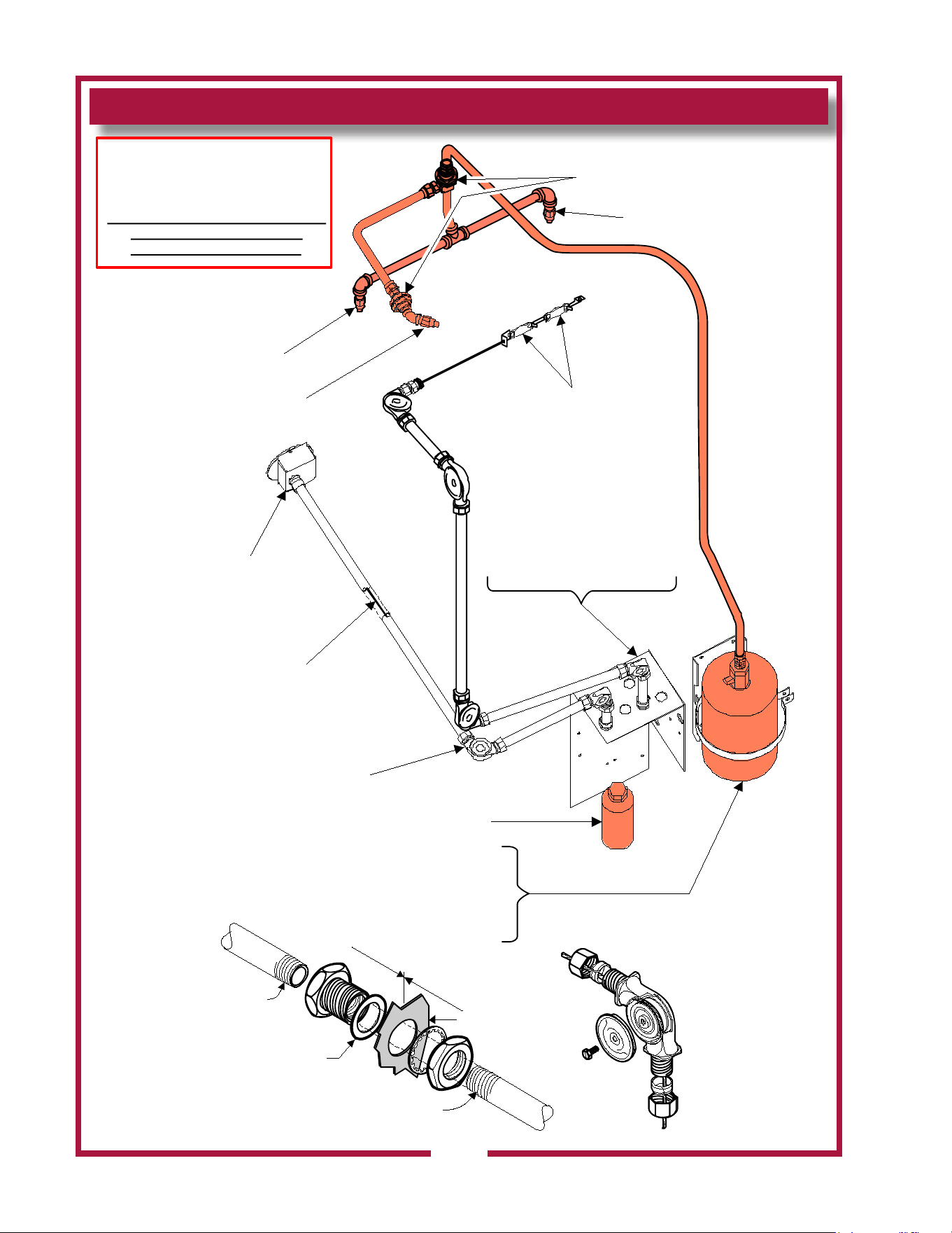
ANSUL® FIRE SUPPRESSION SYSTEM COMPONENTS
30
ref. CABLE, WIRE ROPE
ANSUL© p/n 15821 (50’/15m)
79653 (500’/152m) (typical)
ASSY, PULL STATION
ANSUL© 501389
FRO NT OF UNIT
ref. PULLEY ELBOW
ANSUL© p/n 423250
(typi cal)
ref. NOZZLE 1W
ANSUL© p/n 419336
r ef. NOZ Z LE 290
ANSUL© p/n 419342
ref. NOZZLE 290
ANSUL© p/n 419342
ref. ADAPTER, QUICK-SEAL 3/8”
ANSUL© p/n 77284
FOR US E ONLY BY AUTHO RIZED
ANSUL© SERVICE PERSONNEL
Refer to Ansul© part no. 418078-05
R-102 Restaurant Fire Suppression
System Design, Installation,
Recharge and Maintenance
ref. TANK 1.5 GAL, ANSULEX®
ANSUL© p/n 429864
(NOT S HO WN)
ANSULEX ® EXTINGUISHING AGENT
1.5 GAL. ANSUL© p/n 79694
CART RIDGE LT-20-R
ANSUL© p/n 67099
BACK OF UNIT
ANSUL© p/n 77284
DE TA I L
i
n
s
i
d
e
o
u
ts
i
d
e
cabinet wall
Seal with
Teflon tape
Seal with
Teflon tape
Fiber
washer
is always
on the inside
ANSUL© p/n 423250
DE TA I L
Cable sits in
groove in
pulley
FUSIBLE LINK
212ºF TYPE B
504112
ref. MO UNTING BRA CKE T
RELEASE MECHANISM
R-102 ANSUL© p/n 79493
(NO T SHOW N)
MICROSWITCH 67273
TERM.BLOCK 53068
M506 2M-304964 Owners Manual WVOC-4H
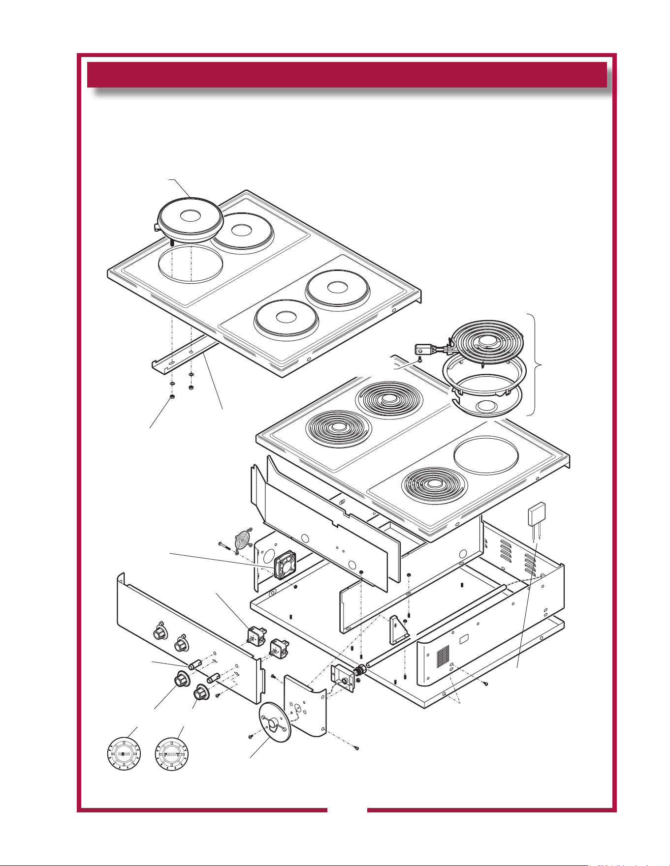
EXPLODED VIEW & PARTS LIST
31
COOKTOP SECTION COMPONENTS
OFF
0
LO
HI
FRONT
2
3
4
5
6
7
8
OFF
0
LO
HI
REAR
2
3
4
5
6
7
8
PULL
HANDLE
IN CASE OF
FIRE
ANSUL
LIGHT, SIGNAL
AMBER 2J-30516
KNOB, HOTPLATE
REAR 2R-30584
KNOB, HOTPLATE
FRONT 2R-30583
ASSEMBLY, REMOTE PULL
STATION 2O-301389
INFINITE SWITCH
240V A CAM 2E-30562
FAN, COOLING
FT 2U-303655
Thermal Protector
2T-303892
NUT, 8-32 KEPS
Ni 2C-31053
BRACKET, HOLD-DOWN
SOLID ELEMENT DD-501451
HEATING ELEMENT,
SOLID 240V 2000W
WS-503973
HF
WS-50293
COMPLETE
ASSEMBLY
SCREW 8-32 x 3/8
(pk 100) 2C-33890
HS
IL1983, Rev. A
M506 2M-304964 Owners Manual WVOC-4H
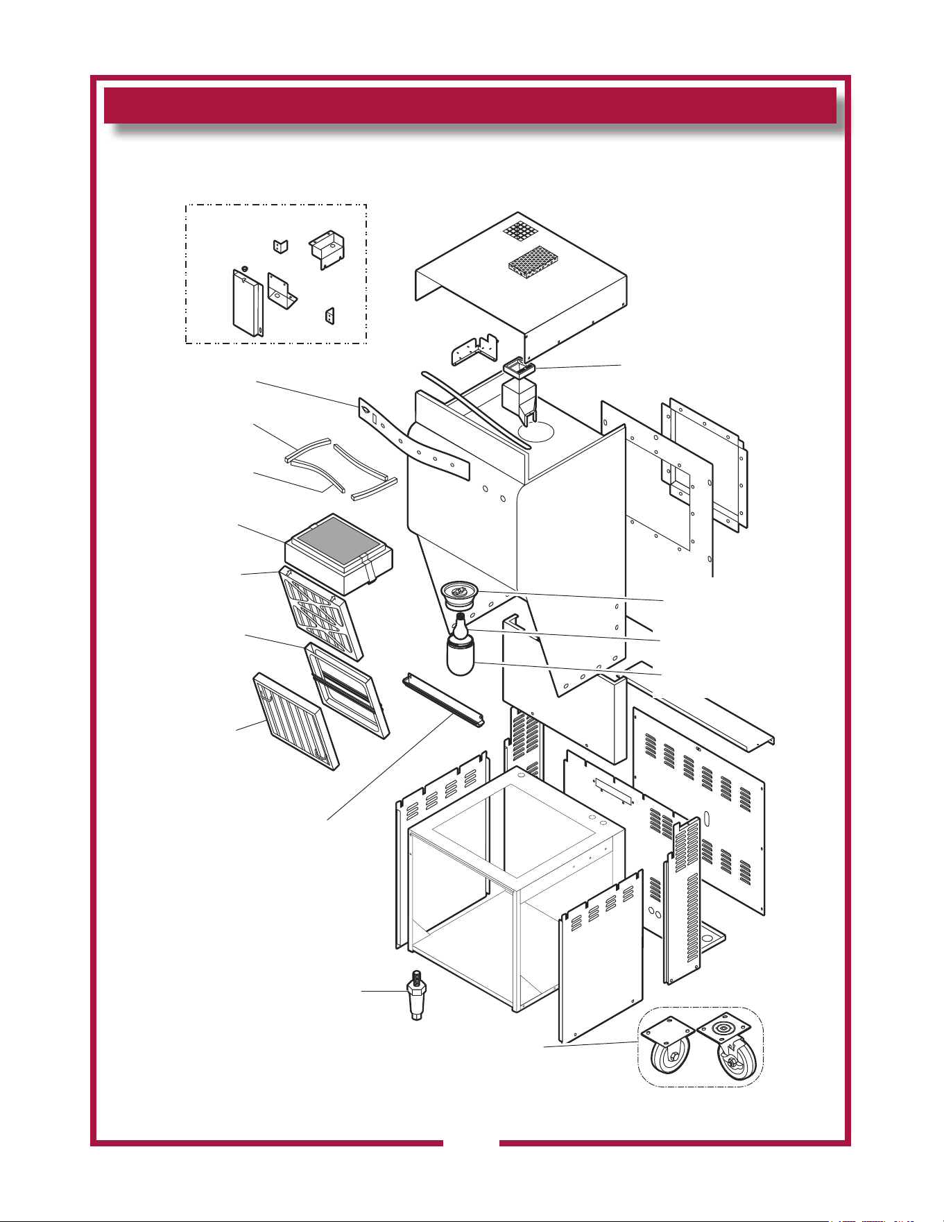
EXPLODED VIEW & PARTS LIST
32
HOOD SECTION - CABINET COMPONENTS
M506 2M-304964 Owners Manual WVOC-4H
IL1984a
INTERNAL BRACKETS
LABEL, CONTROL
PANEL 2M-502782
GASKET, SILICONE
15-1/4” M3-302772
GASKET, SILICONE
18-1/2” WS-502773
ASSY, FILTER PACK
M3-302775
PREFILTER
2I-302579
CAGE,
PRE-FILTER
5M-22683
BAFFLE, GREASE
FILTER (TYPE 3)
2I-302580
GREASE CUP
M3-304405
LEG, ADJUSTABLE
2A-45598
HOUSING, LIGHT
SOCKET 2E-305098
BULB, APPLIANCE
230V 100W 2S-305100
GLASS GLOBE, LIGHT
BULB COVER 2Q-305099
LEG, ADJUSTABLE
VCS 5M-22617
(REAR LEG OPTION)
SET, CASTERS
DD-38762
(2 swivel, 2 fixed)
FIRE DAMPER ASSY
280ºF (ref. 2V-301187)
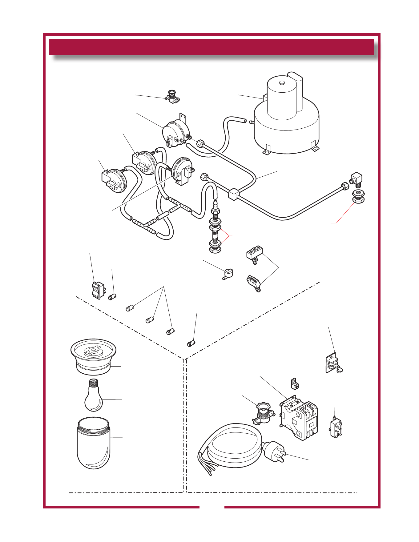
EXPLODED VIEW & PARTS LIST
33
HOOD SECTION - ELECTRICAL & VACUUM COMPONENTS
M506 2M-304964 Owners Manual WVOC-4H
FRONT OF HOOD
ELECTRICAL - UPPER HOOD
ELECTRICAL - UNDER HOOD
ELECTRICAL - REAR OF LOWER CABINET
ref Ansul®
77284
ref Ansul®
77284
FITTING, 1/2” CONDUIT
STRAIGHT 2K-37748X
ASSY, BLOWER
240V 2U-302584
VACUUM SWITCH
#4 2E-Z24058
VACUUM SWITCH
#1 2E-Z24055
VACUUM SWITCH
#3 2E-Z24057
VACUUM SWITCH
#2 2E-Z24056
ASSY, VAC TUBE
MANIFOLD N1-302588
SWITCH, POWER
2E-70395
LIGHT, INDICATOR
GREEN 240V 2J-35697
LIGHT, INDICATOR
AMBER 240V 2J-30516 (3 pl)
LIGHT, INDICATOR
RED 240V 2J-31157
BUZZER, 240V
2J-44834
SWITCH, FILTER
INTERLOCK
2E-300407 (2 pl)
HOUSING, LIGHT
SOCKET 2E-305098
BULB, APPLIANCE
230V 100W 2S-305100
GLASS GLOBE
LIGHT BULB
COVER 2Q-305099
TERMINAL BLOCK
2P 250V 53068
JUMPER, FLAME
SENSOR 2E-34005
STRAIN RELIEF
1-1/4” 2K-304420
RELAY, BLDG
FIRE ALARM
2E-44514
POWER CORD
NEMA 15-60P
M3-303130
(incl. strain relief)
IL1985c
CONTACTOR 208/240V
75A 3PH 2E-Z15704
75A 1PH 2E-306040
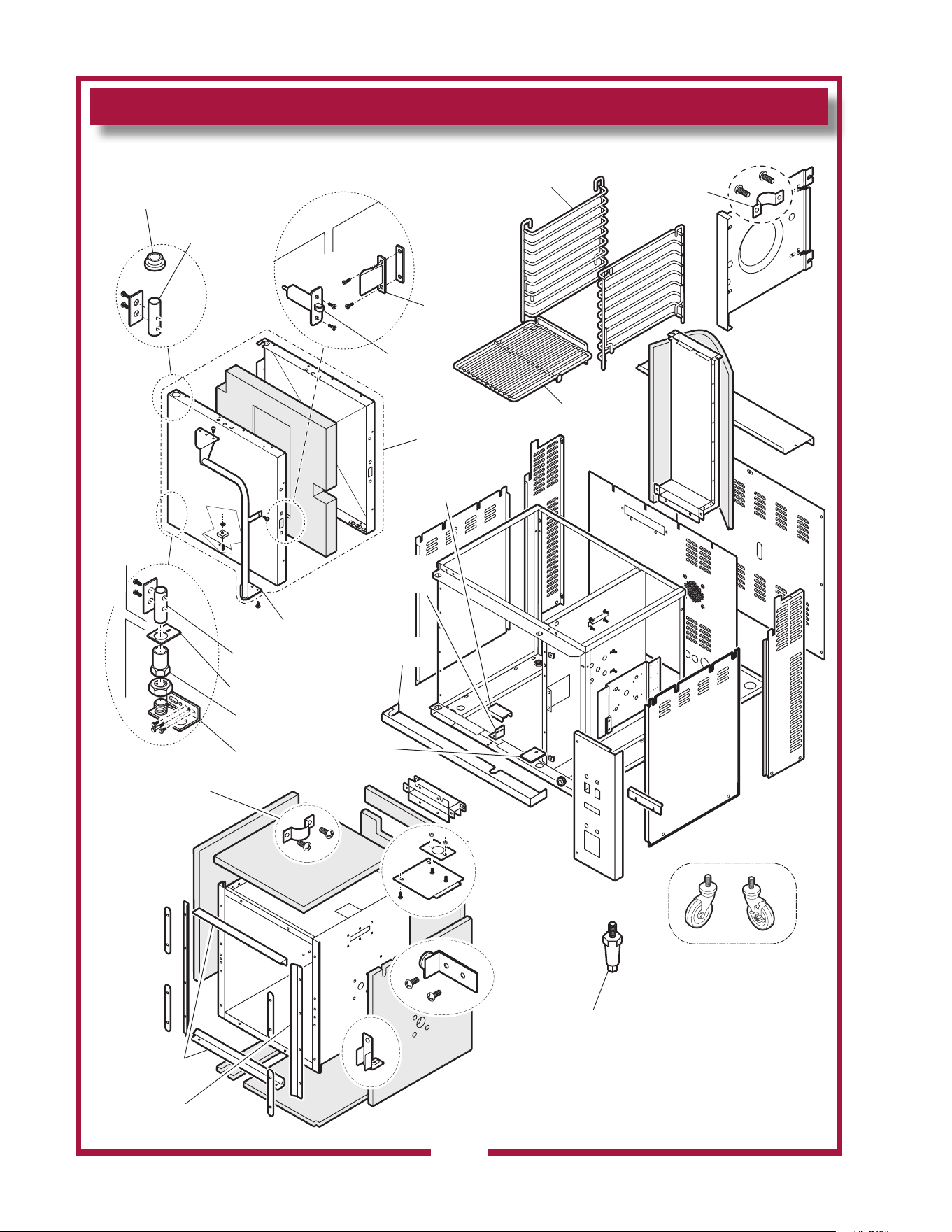
EXPLODED VIEW & PARTS LIST
34
CONVECTION OVEN SECTION - CABINET COMPONENTS
M506 2M-304964 Owners Manual WVOC-4H
PLATE
COVER
F6-43899
GUARD, PROX.
SWITCH F6-45647
OVEN RACK
5F-21376
SUPPORT,
OVEN RACK
5F-21375
CLIP, RACK
SUPPORT
F6-43889
BRACKET
PROX. SWITCH
F6-43787
TRIM, LOWER
FRONT F6-43804
CABINET DOOR
DOOR
CABINET
BUSHING, TOP
HINGE 2K-305619
PIN, HINGE
2A-305610
DOOR LATCH
2C-305615
DOOR STRIKER
2C-305616
ASSEMBLY, DOOR
COMPLETE
F6-504444
HANDLE
2R-305612
PIN, HINGE
2A-305610
PLATE, DOOR
PIVOT F6-43899
SLEEVE, DOOR
HINGE 2A-43900
HINGE, DOOR
LOWER F6-43896
HINGE, DOOR
LOWER F6-43896
GASKET, DOOR
TOP/BOT F6-46314
GASKET, DOOR
SIDE F6-46313
SET, CASTERS 5F-21372
(2 swivel casters, thd stem)
SET, CASTERS 5F-21330
(2 swivel caster w/brake)
SET, CASTERS 5F-21330
(2 swivel, 2 swivel w/brake)
LEG, ADJUSTABLE
2A-45598
IL1986
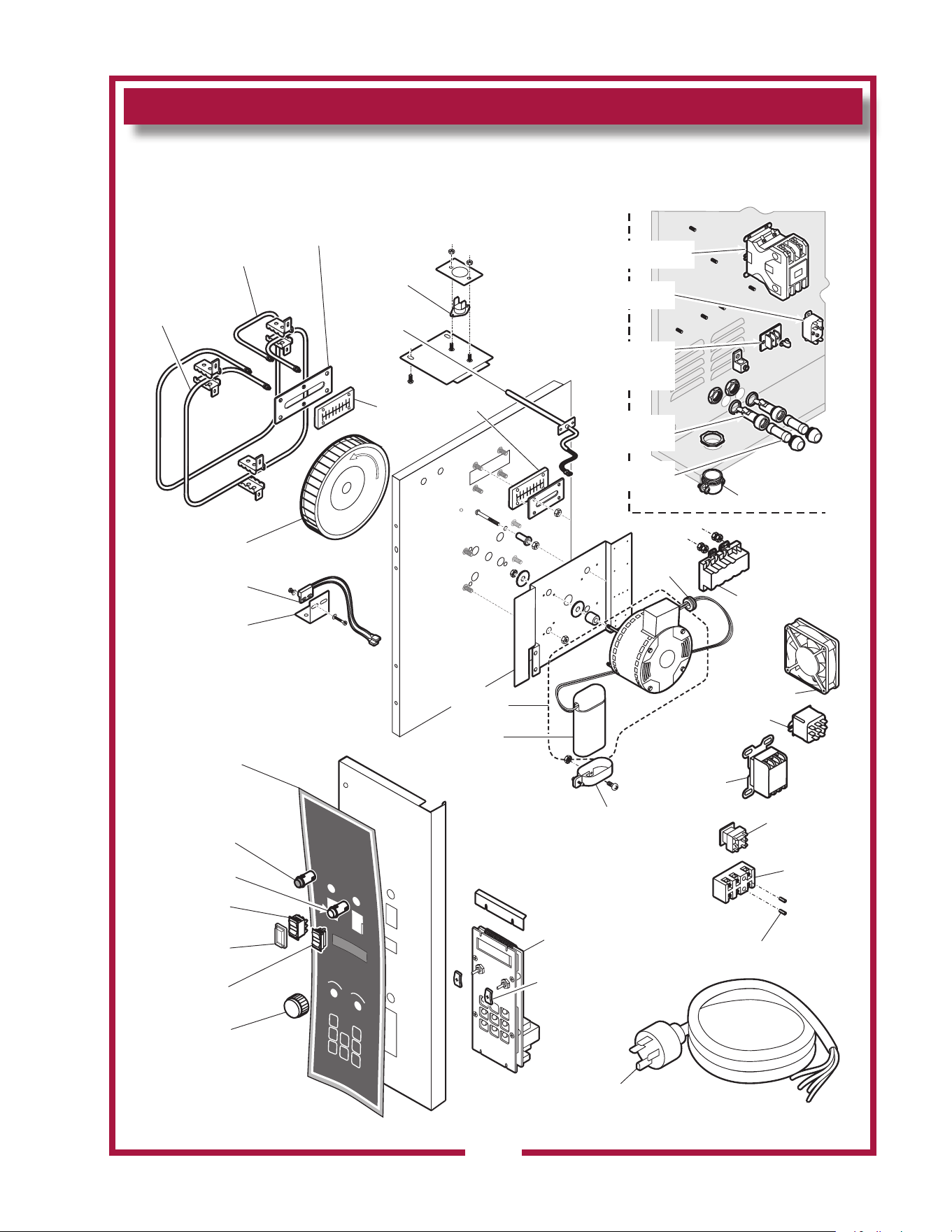
EXPLODED VIEW & PARTS LIST
35
CONVECTION OVEN SECTION - ELECTRICAL COMPONENTS
M506 2M-304964 Owners Manual WVOC-4H
RELAY, HI-LIMIT
(240V) 2E-307328
RELAY, E-SAFE
(208/240V) 2E-306967
(380-415V) 506967A
CONTACTOR,
(208V) 2E-37779
COVER, GASKET
INNER F6-43836
ELEMENT,
4” SPACING
2N-43872UL (208V)
2N-43783UL (240V)
WHEEL, BLOWER
2U-43797
SWITCH, PROXIMITY
F6-45239
BRACKET, PROX.
SWITCH F6-43787
LIGHT, SIGNAL
WHITE 2J-40877
LIGHT, SIGNAL
RED 2J-31157
SWITCH DTDP
CTR OFF 2E-45651
BOOT, SWITCH
SEAL 2E-43738
SWITCH
SPDT 2E-45657
KNOB, OC-1
2R-47439
THERMO,
HI-LIMIT 2T-45180
PROBE, TEMP
OC-1 2J-304712
GASKET, ELEMENT
2I-43834
MOTOR, 1/4 HP
208/230V
WS-63932
CONTROLLER, TIME/TEMP
OVEN WS-504713
GASKET, CLOSED-CELL
OVEN POTENTIOMETER
M3-303252
NUT, 8-32 x7/8
Alu 2C-41974
TERMINAL
BLOCK
3P WS-50131
RELAY DPDT
208/240V
2E-43880
BRACKET, START
CAPACITOR 2V-300933
CAPACITOR,
MOTOR START
WS-69823
GROMMET
2K-31040
ELEMENT,
2.5” SPACING
2N-43866UL (208V)
2N-43800UL (240V)
FAN, COOLING
2U-44687
OVERLAY, CONTROL
PANEL 2M-47441
POWER CORD
NEMA 15-60P
M3-303130
(incl/ strain relief)
BACK OF UNIT
STRAIN RELIEF
1-1/4 NPT 2K-304420
FUSE SC-10
2E-34768
FUSEHOLDER
HPA-EE 10A
2E-34769
TERMINAL BLOCK
FIRE ALARM 53068
JUMPER, FLAME
SENSOR 2E-34005
RELAY, BLDG
FIRE ALARM 2E-44514
CONTACTOR 208/240V
3ø 50a 2E-302789
IL1987c

WIRING DIAGRAM
36
HOOD SECTION
M506 2M-304964 Owners Manual WVOC-4H
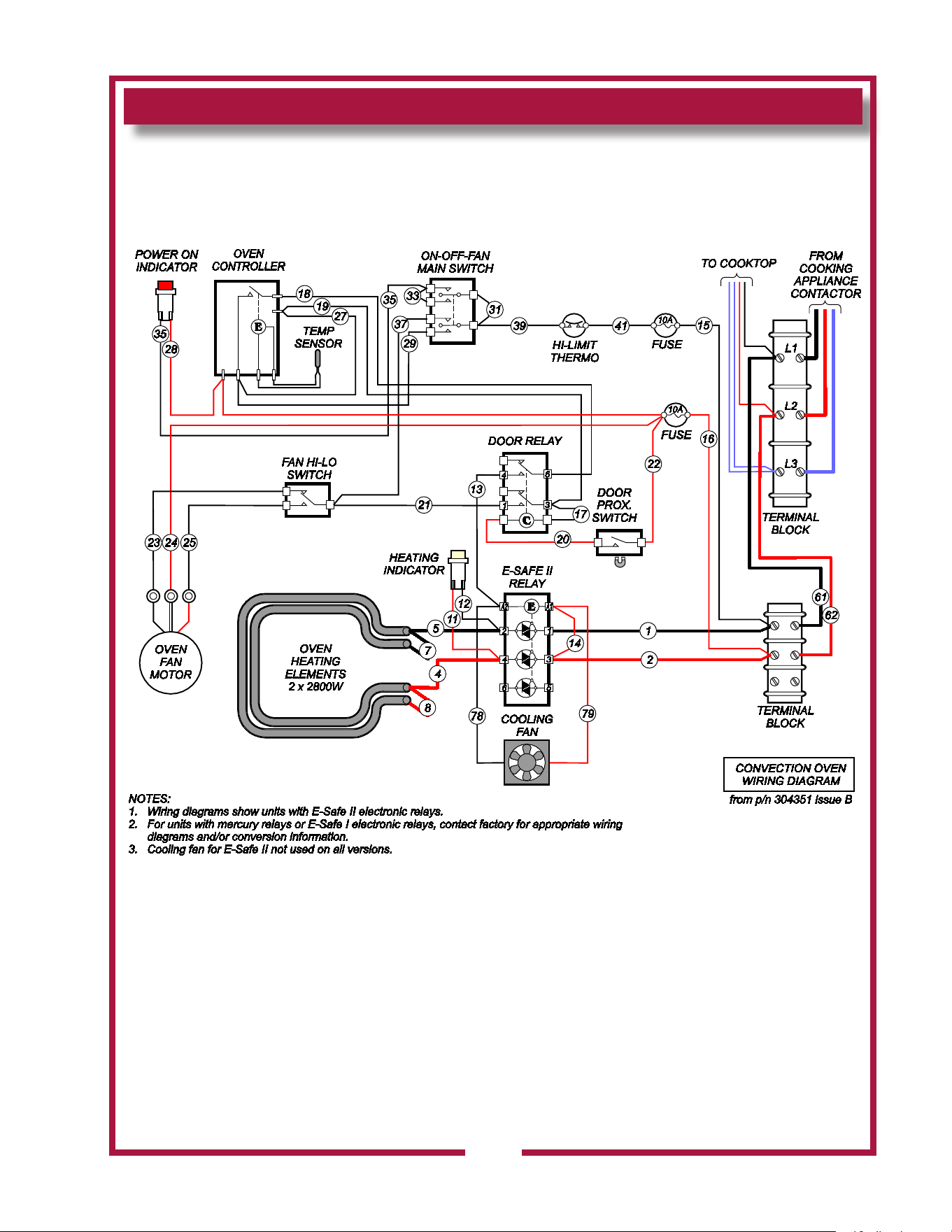
WIRING DIAGRAM
37
CONVECTION OVEN SECTION
M506 2M-304964 Owners Manual WVOC-4H
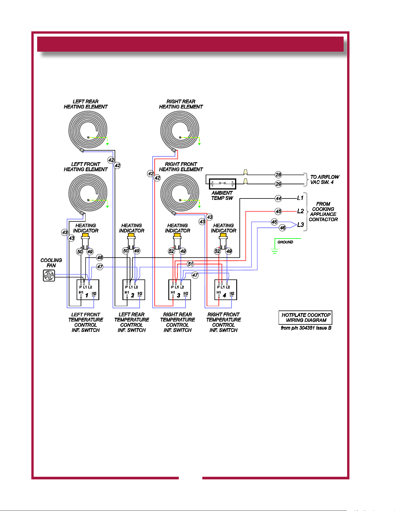
WIRING DIAGRAM
38
HOTPLATE COOKTOP SECTION
M506 2M-304964 Owners Manual WVOC-4H

NOTES
39
M506 2M-304964 Owners Manual WVOC-4H

NOTES
40
M506 2M-304964 Owners Manual WVOC-4H

DESCRIPTION SERVICE
PART NO.
OVEN RACK Replacement 2B-43784
PRE-FILTER 2I-302579
PRE-FILTER CAGE WS-22683
FILTER PACK (HEPA + CHARCOAL) M3-302775
GREASE BAFFLE 2I-302580
GREASE CUP DD-302708
LEG KIT WS-22829
CASTERS 2P-43763
DRIP TRAY, 8” (Spiral Hotplate) I7-30292
SCRAPER, CLEANING(Ceramic Hotplate) 2R-302040
CLEANING CREME, CERAMIC HOTPLATE 2L-301124
NOTE: Ansul® Manual 418087-05 IS intended
for use by authorized Ansul® service personnel
only. Ansul® Manual 418087-05 must be obtained
through your authorized Ansul® distributor.
PARTS & SERVICE
CUSTOMER SERVICE DATA
please have this information available if calling for service
RESTAURANT _____________________________ LOCATION _____________
INSTALLATION DATE ________________________ TECHNICIAN ___________
SERVICE COMPANY ________________________________________________
ADDRESS ___________________________ STATE ______ ZIP__________
TELEPHONE NUMBER (_____)_____-_________
EQUIPMENT MODEL NO. _____________ EQUIPMENT SERIAL NO. _______________
VOLTAGE: (check one) 208 240
41
IMPORTANT: Use only
factory authorized service parts
and replacement lters.
For factory authorized service,
or to order factory authorized
replacement parts, contact
your Wells authorized service
agency, or call:
Wells Manufacturing
10 Sunnen Dr.,
St. Louis MO 63143 USA
Service Dept.
phone: (800) 264-7827
Service Parts Department
can supply you with the name
and telephone number of
the WELLS AUTHORIZED
SERVICE AGENCY
nearest you.
M506 2M-304964 Owners Manual WVOC-4H
WELLS MANUFACTURING
265 Hobson Street, Smithville, Tennessee 37166
telephone: 800-264-7827
www.wells-mfg.com