WELLS BLOOMFIELD, LLC
10 Sunnen Dr., St. Louis, MO 63143
telephone: 314-678-6314
fax: 314-781-2714
www.wells-mfg.com
IMPORTANT: DO NOT DISCARD THIS MANUAL
This manual is considered to be part of the appliance and is to be given to the OWNER or
MANAGER of the restaurant, or to the person responsible for TRAINING OPERATORS of
this appliance. Additional manuals are available from your WELLS DEALER.
THIS MANUAL MUST BE READ AND UNDERSTOOD BY ALL PERSONS USING OR
INSTALLING THIS APPLIANCE. Contact your WELLS DEALER if you have any
questions concerning installation, operation or maintenance of this equipment.
507
p/n 2M-304446 Rev. F M507 120209
OWNERS MANUAL
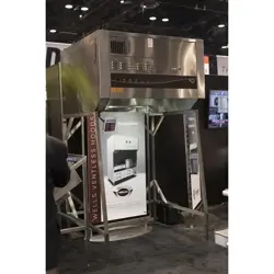
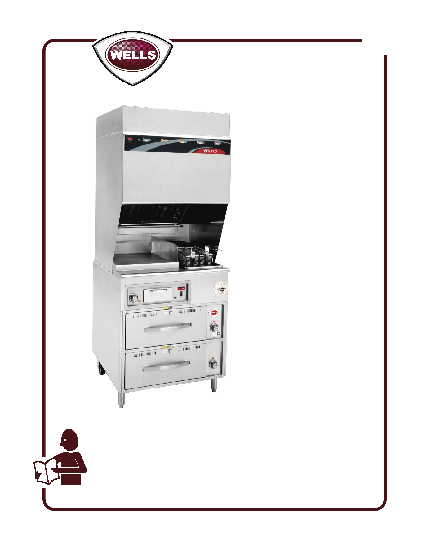
WV-FG SERIES
GRIDDLE / FRYER
COOKTOP
with
UNIVERSAL HOOD
MODELS
WV-FG
WV-FGRW
Includes
INSTALLATION
USE & CARE
EXPLODED VIEW
PARTS LIST
WIRING DIAGRAM
Model
WV-FGRW

M507 p/n 2M-304446 Owners Manual WV-FG
Unless otherwise specified, all commercial cooking
equipment manufactured by WELLS BLOOMFIELD, LLC is
warranted against defects in materials and workmanship for
a period of one year from the date of original installation or
18 months from the date of shipment from our factory,
whichever comes first, and is for the benefit of the original
purchaser only.
THIS WARRANTY IS THE COMPLETE AND ONLY
WARRANTY, EXPRESSED OR IMPLIED IN LAW OR IN
FACT, INCLUDING BUT NOT LIMITED TO, WARRANTIES
OF MERCHANTABILITY OR FITNESS FOR ANY
PARTICULAR PURPOSE, AND/OR FOR DIRECT,
INDIRECT OR CONSEQUENTIAL DAMAGES IN
CONNECTION WITH WELLS BLOOMFIELD PRODUCTS.
This warranty is void if it is determined that, upon inspection
by an authorized service agency, the equipment has been
modified, misused, misapplied, improperly installed, or
damaged in transit or by fire, flood or act of God. It also
does not apply if the serial nameplate has been removed, or
if service is performed by unauthorized personnel. The
prices charged by Wells Bloomfield for its products are
based upon the limitations in this warranty. Seller’s
obligation under this warranty is limited to the repair of
defects without charge by a Wells Bloomfield factory
authorized service agency or one of its sub-service
agencies. This service will be provided on customer’s
premises for non-portable models. Portable models (a
device with a cord and plug) must be taken or shipped to
the closest authorized service agency, transportation
charges prepaid, for service. In addition to restrictions
contained in this warranty, specific limitations are shown in
the Service Policy and Procedure Guide. Wells Bloomfield
authorized service agencies are located in principal cities.
This warranty is valid in the United States and Canada and
void elsewhere. Please consult your classified telephone
directory, your foodservice equipment dealer or contact:
Wells Bloomfield, LLC
10 Sunnen Dr., St. Louis MO 63143 USA
phone (314) 678-6314 or fax (314) 781-2714
for information and other details concerning warranty.
LIMITED WARRANTY STATEMENT
SERVICE POLICY AND PROCEDURE GUIDE and ADDITIONAL WARRANTY EXCLUSIONS
NOTE: For your protection, please note that equipment in
this shipment was carefully inspected and packaged by
skilled personnel before leaving the factory. Upon
acceptance of this shipment, the transportation company
assumes full responsibility for its safe delivery.
IF SHIPMENT ARRIVES DAMAGED:
1. VISIBLE LOSS OR DAMAGE: Be certain that any
visible loss or damage is noted on the freight bill or
express receipt, and that the note of loss or damage is
signed by the delivery person.
2. FILE CLAIM FOR DAMAGE IMMEDIATELY:
Regardless of the extent of the damage.
3. CONCEALED LOSS OR DAMAGE: if damage is
unnoticed until the merchandise is unpacked, notify the
transportation company or carrier immediately, and file
“CONCEALED DAMAGE” claim with them. This
should be done within fifteen (15) days from the date
the delivery was made to you. Be sure to retain the
container for inspection.
Wells Bloomfield cannot assume liability for damage or loss
incurred in transit. We will, however, at your request, supply
you with the necessary documents to support your claim.
SHIPPING DAMAGE CLAIM PROCEDURE
xi
1. Resetting of safety thermostats, circuit breakers, over
load protectors, and/or fuse replacements are not
covered by this warranty unless warranted conditions
are the cause.
2. All problems due to operation at voltages or phase
other than specified on equipment nameplates are
not covered by this warranty.
Conversion to correct voltage and/or phase must be
the customer’s responsibility.
3. All problems due to electrical connections not made
in accordance with electrical code requirements
and wiring diagrams supplied with the equipment are
not covered by this warranty.
4. Replacement of items subject to normal wear, to
include such items as knobs, light bulbs; and, normal
maintenance functions including adjustments of
thermostats, adjustment of micro switches and
replacement of fuses and indicating lights are not
covered by warranty.
5. Damage to electrical cords and/or plug due to exposure
to excessive heat are not covered by this warranty.
6. Full use, care, and maintenance instructions supplied
with each machine. Noted maintenance and
preventative maintenance items, such as servicing and
cleaning schedules, are customer responsibility. Those
miscellaneous adjustments noted are customer
responsibility. Proper attention to preventative
maintenance and scheduled maintenance procedures
will prolong the life of the appliance.
7. Travel mileage is limited to sixty (60) miles from an
Authorized Service Agency or one of its sub-service
agencies.
8. All labor shall be performed during regular working
hours. Overtime premium will be charged to the buyer.
9. All genuine Wells replacement parts are warranted for
ninety (90) days from date of purchase on non-
warranty equipment. This parts warranty is limited only
to replacement of the defective part(s). Any use of
non-genuine Wells parts completely voids any
warranty.
10. Installation, labor, and job check-outs are not
considered warranty and are thus not covered by this
warranty.
11. Charges incurred by delays, waiting time or operating
restrictions that hinder the service technician’s ability to
perform service are not covered by warranty. This
includes institutional and correctional facilities.
WARRANTY ................................................................ xi
SPECIFICATIONS ....................................................... 1
FEATURES & OPERATING CONTROLS ................... 2
PRECAUTIONS & GENERAL INFORMATION ........... 6
AGENCY LISTING INFORMATION ............................. 10
INSTALLATION ........................................................... 11
OPERATION ................................................................ 16
CLEANING INSTRUCTIONS ....................................... 21
MAINTENANCE INSTRUCTIONS ............................... 26
TROUBLESHOOTING SUGGESTIONS ..................... 29
MAINTENANCE SCHEDULES .................................... 30
MSDS (Ansulex Low pH) ............................................. 33
ANSUL® COMPONENTS ........................................... 35
EXPLODED VIEW & PARTS LIST .............................. 36
WIRING DIAGRAM ...................................................... 41
PARTS & SERVICE ..................................................... 45
CUSTOMER SERVICE DATA .................................... 45
Thank You for purchasing this Wells Bloomfield appliance.
Proper installation, professional operation and consistent maintenance of this appliance will ensure that
it gives you the very best performance and a long, economical service life.
This manual contains the information needed to properly install this appliance, and to use and care for
the appliance in a manner which will ensure its optimum performance.
TABLE OF CONTENTS
SPECIFICATIONS
INTRODUCTION
1
M507 p/n 2M-304446 Owners Manual WV-FG
MODEL
DRAWER
WARMER
VOLTS
60Hz
3ø AMPS
1ø
AMPS
WATTS
L1 L2 L3
WV-FG
NO
208V 30 43 24 52 10,800
240V 26 40 24 49 11,700
WVV-GRW
WV-FGRWT
YES
208V 32 43 26 55 11,500
240V 28 40 27 53 12,600
BACK SIDE BOTTOM TOP
inches n/a 6 6 19
millimeters n/a 152 152 483
Minimum clearances required from unit to nearest combustible surface or object
FEATURES & OPERATING CONTROLS
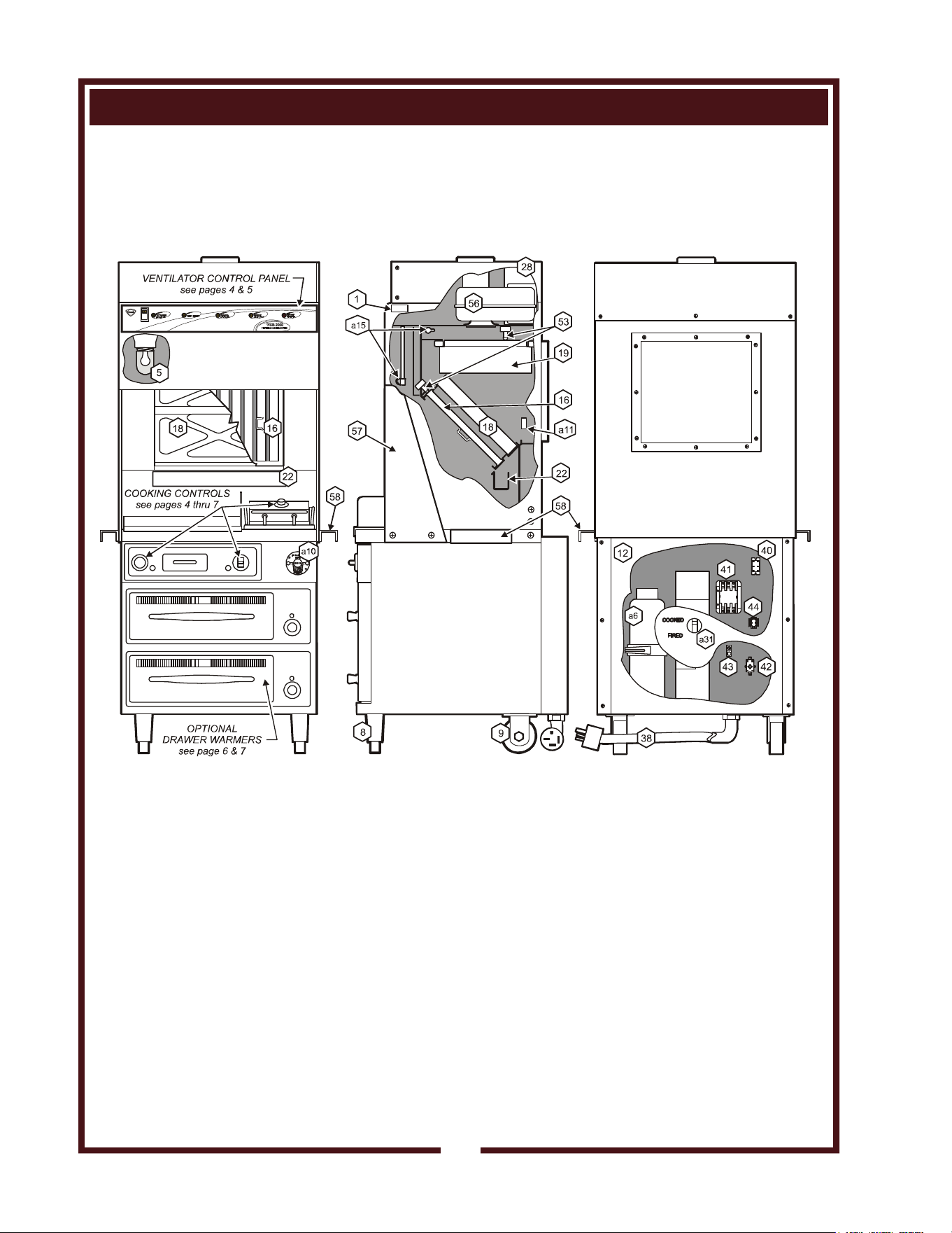
Fig. 1 Ventilator Section Operating Features & Controls
2
M507 p/n 2M-304446 Owners Manual WV-FG

ITEM
1.
5.
a6.
8.
9.
a10.
a11.
12.
a15.
16.
18.
19.
22.
28.
a31.
38.
41.
42.
43.
44.
53.
56.
57.
58.
DESCRIPTION
NAMEPLATE
APPLIANCE LIGHT
FIRE SUPPRESSION
AGENT TANK (1.5 gal.)
ADJUSTABLE (FRONT) LEG
RIGID (REAR) CASTER
MANUAL PULL STATION
FUSIBLE LINKS
LOWER REAR ACCESS
PANEL
DISCHARGE NOZZLE
GREASE BAFFLE
PRE-FILTER ASSEMBLY
HI-EFFICIENCY/CHARCOAL
FILTER PACK
GREASE DRIP TRAY
VENTILATOR EXHAUST
DUCT
STATUS INDICATOR
POWER CORD
POWER CONTACTOR
BUILDING FIRE ALARM
RELAY
GROUND LUG
INTERLOCK TERMINAL
FILTER INTERLOCK
SWITCHES
VENTILATOR FAN
HOOD SIDE SHIELD
SIDE SPACERS
COMMENT
Gives manufacturer, make and model description. Also lists voltage
and amperage data.
ON when hood power switch is ON. Illuminates cooktop.
Container for Ansulex™ Low-pH liquid fire suppression liquid.
Allows the unit to be leveled.
Allows the unit to be easily positioned by lifting the front of the unit
slightly.
Provides a means of manual activation of the fire suppression system.
PULL ONLY IN CASE OF FIRE!
Designed to break at rated temperature. Breaking (i.e. fire on the
cooktop) activates fire suppression system. Should be replaced at
least once per year.
Allows access to Ansul® fire suppression agent tank (a6) and controls
also access to main power contactor (41).
Fire suppression media discharges here (2 places).
Extracts and drains most grease and moisture from the air flow.
Comprises the PRE-FILTER FRAME and a replaceable
PRE-FILTER. Stops larger particles of grease from reaching the
FILTER PACK for reduced maintenance costs.
Stops most grease and smoke particles. Also assists in some cooking
odor removal.
Collects grease/moisture dripping from grease baffle(16).
Exit point for ventilator airflow - on top left rear of unit.
DO NOT BLOCK
Displays status of fire suppression system (COCKED - FIRED) If
FIRED, a buzzer will sound continuously.
6’ cord and cap. Plug for NEMA 15-60R (receptacle by user).
Energizes cooking appliances only while ventilator section is sensed
as operational.
Reports fire alarm condition to building fire management system.
Ground wire of power cord connects here.
Provides connection for shut-down control by building fire management
system.
Proper installation of grease baffle and filter pack close these switches
in ventilator sensor circuit.
Provides air movement for ventilation.
Required on left and right sides of hood. Factory installed.
Required to maintain 6" spacing from combustibles. Field installed.
FEATURES & OPERATING CONTROLS (continued)
VENTILATOR SECTION
3
M507 p/n 2M-304446 Owners Manual WV-FG
FEATURES & OPERATING CONTROLS (continued)
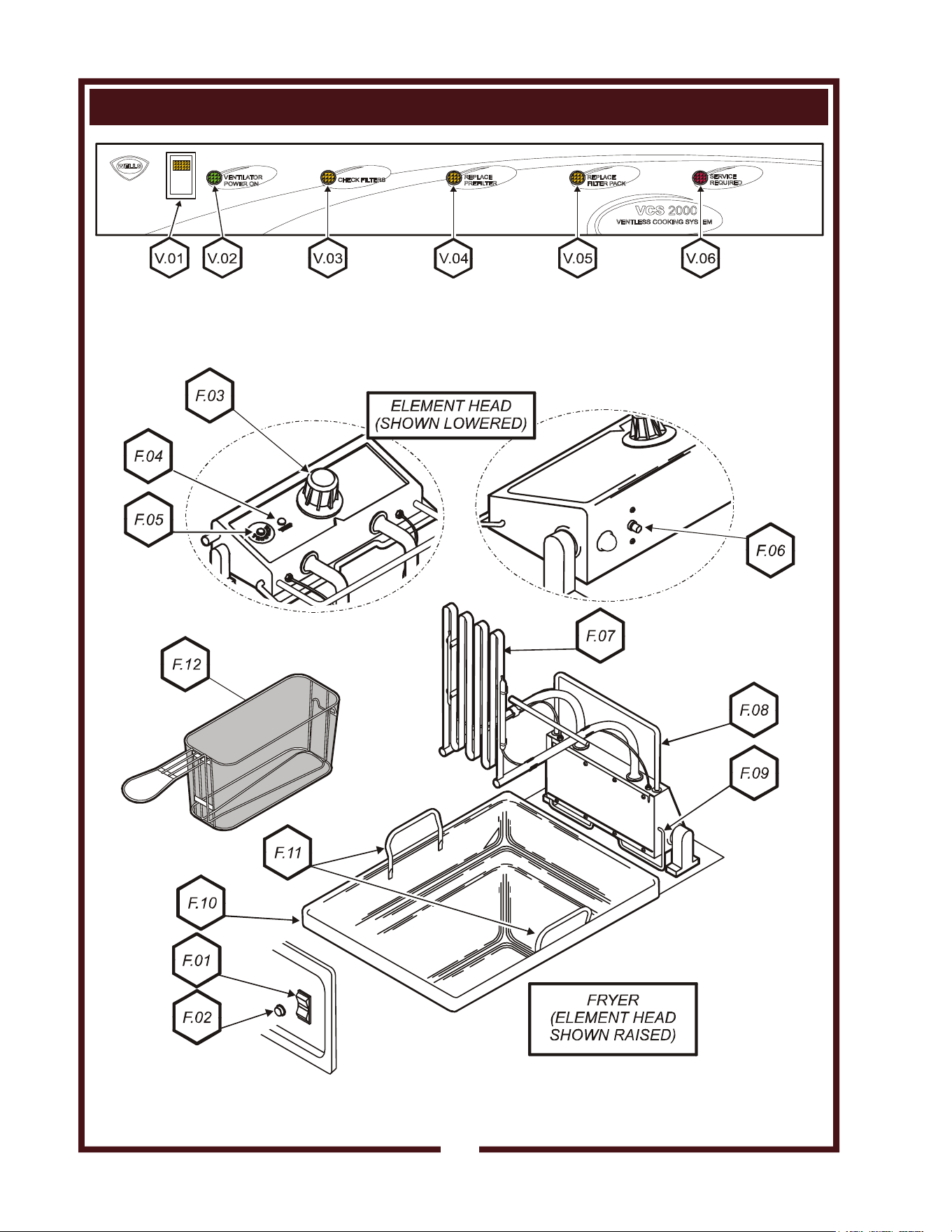
Fig. 2 Ventilator Section Controls & Indicator Lights
4
Fig. 3 Fryer Section
M507 p/n 2M-304446 Owners Manual WV-FG

ITEM
V.01
V.02
V.03
V.04*
V.05*
V.06*
F.01
F.02
F.03
F.04
F.05
F.06
F.07
F.08
F.09
F.10
F.11
F.12
DESCRIPTION
POWER SWITCH
POWER ON INDICATOR
CHECK FILTERS ALARM
INDICATOR
REPLACE PREFILTER ALARM
INDICATOR
REPLACE FILTER PACK ALARM
INDICATOR
SERVICE REQUIRED ALARM
INDICATOR
FRYER POWER SWITCH
FRYER POWER INDICATOR
TEMPERATURE CONTROL
TEMP INDICATOR
HI-LIMIT INDICATOR
HI-LIMIT SAFETY RESET
HEATING ELEMENT
BASKET RACK
ELEMENT HEAD SUPPORT ROD
FRYPOT
FRYPOT HANDLES
FRYER BASKET
COMMENT
Energizes BLOWER MOTOR. If, after 10 seconds, proper conditions are met,
cooking appliances are energized.
APPLIANCE LIGHT is ON when POWER SWITCH is ON.
GREEN. Glows when POWER switch is ON.
AMBER. Glows if one or more filters are out of position. Check all filters and
baffles for proper installation.
AMBER. Glows when PREFILTER is approaching the end of its service life and
must soon be replaced.
AMBER. Glows when FILTER PACK is approaching the end of its service life
and must soon be replaced.
RED. Glows when PREFILTER and/or FILTER PACK has reached the end of
its service life and is too loaded to allow sufficient air flow. Filter MUST be
replaced. Appliance is SHUT DOWN until expended filters are replaced.
Energizes FRYER SECTION.
Glows when FRYER POWER SWITCH is ON.
Thermostatic control of cooking oil temperature.
Glows when HEATING ELEMENT is energized. Goes out when oil is up to
temperature.
Glows if HI-LIMIT SAFETY is TRIPPED.
Interrupts power to HEATING ELEMENT (red button pops out) if oil exceeds
safe temperature. Press red button to reset after oil has cooled.
Heating portion of ELEMENT HEAD. Includes heating element, temperature
control thermobulb and hi-limit safety thermobulb.
Hang FRYER BASKET here to load or drain. Also used as a handle to raise or
lower the ELEMENT HEAD.
Spring loaded to automatically support the ELEMENT HEAD in the raised
position. In order to lower the ELEMENT HEAD the SUPPORT ROD must be
released by rotating forward.
Holds cooking oil. Removable for cleaning.
Used to hold FRYPOT when installing or removing from appliance.
Holds product for loading / frying / draining.
FEATURES & OPERATING CONTROLS (continued)
* See PRECAUTIONS & GENERAL INFORMATION, pages 8 for special procedures regarding prefilters and filter packs.
VENTILATOR SECTION CONTROLS
5
FRYER SECTION
M507 p/n 2M-304446 Owners Manual WV-FG
FEATURES & OPERATING CONTROLS (continued)
6
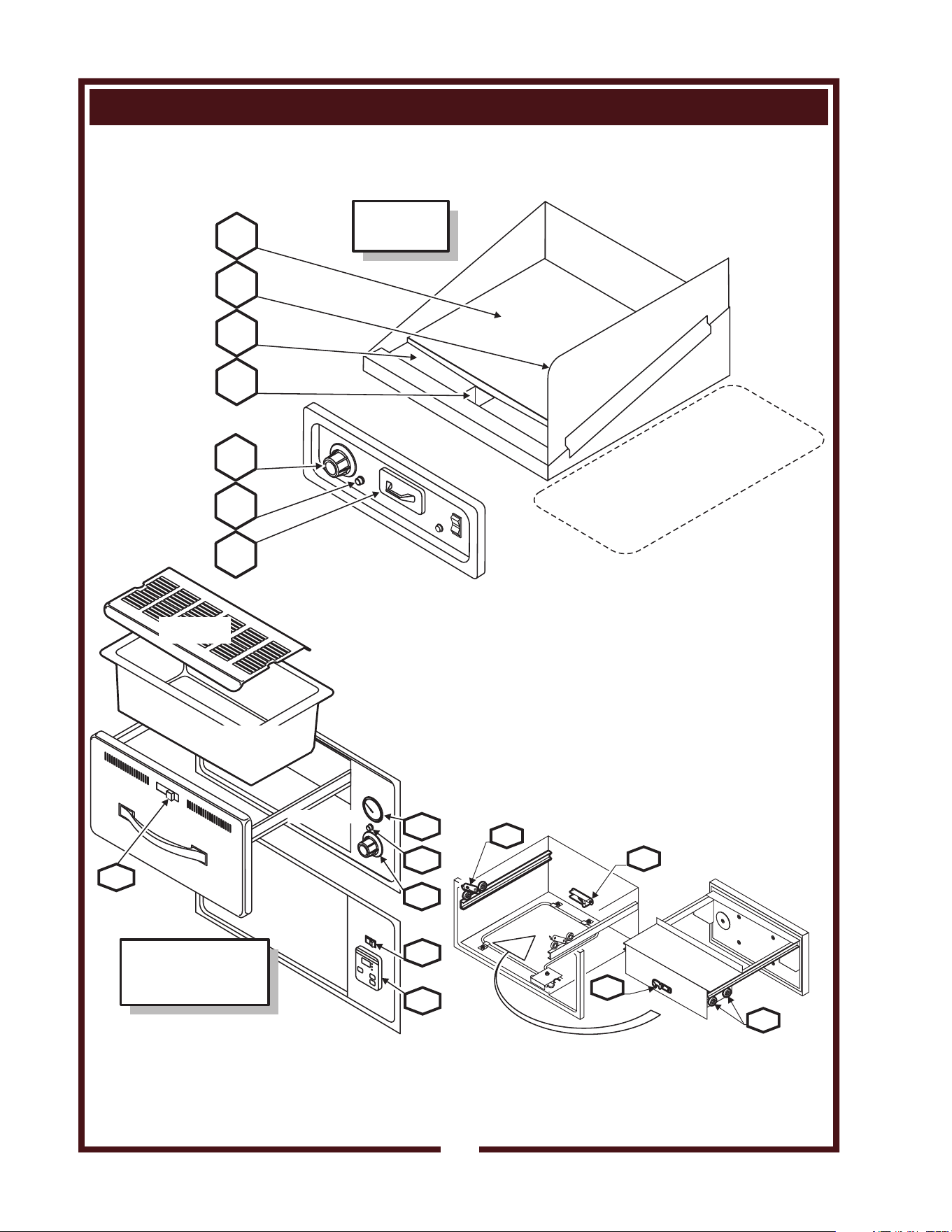
Fig. 4 Griddle and Drawer Warmer Sections
G.01
G.02
G.03
FRYER
G.04
G.05
G.06
G.07
GRIDDLE
SECTION
W.06
W.06
W.05
W.07
W.04
W.01
W.09
W.03
W.02
W.08
RWT-STYLE
RW-STYLE
DRAWER
INSERT PAN
HUMITROL
RACK
OPTIONAL
DRAWER WARMER
SECTION
M507 p/n 2M-304446 Owners Manual WV-FG

ITEM
G.01
G.02
G.03
G.04
G.05
G.06
G.07
DESCRIPTION
GRIDDLE TEMPERATURE
CONTROL
GRIDDLE HEAT INDICATOR
GREASE DRAWER
COOKING SURFACE
SPLATTER SHIELD
WASTE TROUGH
WASTE CHUTE
COMMENT
Thermostatic control of griddle temperature
Glows when heating elements are energized.
Collects cooking waste from GRIDDLE. Removable for cleaning.
Heated portion for cooking food.
Helps control grease splatter and contamination between the GRIDDLE and
FRYER sections.
Scrape cooking waste to this area.
Cooking waste moved into GREASE DRAWER thru this opening.
FEATURES & OPERATING CONTROLS (continued)
7
GRIDDLE SECTION
OPTIONAL DRAWER WARMER SECTION
W.01
W.02
W.03
W.04
W.05
W.06
W.07
W.08
W.09
WARMER TEMPERATURE
CONTROL
POWER ON INDICATOR
THERMOMETER (optional)
HUMIDITY CONTROL
DRAWER CATCH
DRAWER STOP
DRAWER ROLLERS
POWER SWITCH (RWT)
CONTROLLER (RWT)
Infinite switch control of temperature of one warmer drawer.
AMBER. Glows when associated temperature control is turned ON.
Reads temperature inside drawer cavity
Must be ordered at time of initial build.
Slide control of shutters to control air circulation within the warmer drawer.
Holds drawer closed.
Prevents drawer from opening too far. Spring loaded to permit easy removal of
drawer.
Support drawer and allow it to open and close smoothly.
Energizes unit (RWT-style only)
Controls cavity temperature. Readout displays setpoint and actual temperature
information. UP ARROW / DOWN ARROW keys allow modification of setpoint
temperature. (RWT-style units only)
M507 p/n 2M-304446 Owners Manual WV-FG
PRECAUTIONS AND GENERAL INFORMATION
8
NOTE: Fire suppression system and all associated components must
only be serviced by an authorized Ansul® Distributor. All setup,
charging, repair and/or adjustment of the fire suppression system must
be performed by an Authorized Ansul® Distributor ONLY.
IMPORTANT: If a remote pull station is installed, both rear casters (9)
must be replaced with legs to deter moving the unit. MOVING AN
APPLIANCE WITH A REMOTE PULL STATION WILL DISCHARGE
THE FIRE SUPPRESSION SYSTEM.
This Ventless Cooking System™ is designed to help reduce odor
emissions, but will not completely eliminate cooking odors. Air
exchange at the installation site must comply with the requirements of
the local jurisdictional authority. To ensure that odors do not build-up,
recommended minimum air exchange is 300 - 400 cfm of outside air
into and out of the area where the unit is used. Recommend use of
wall fan and wall switch, to be supplied by user.
Disconnect this appliance from electrical power before performing any
maintenance or servicing.
Any procedure which requires the use of tools must be performed by a
qualified technician.
Use only genuine Wells replacement parts and filters, call
(314) 678-6314 or your authorized Wells service agent. Parts supplied
by others will void your warranty and may not provide safe operation.
This appliance is not jet stream approved. Do not direct water jet or
steam jet at this appliance, or at any control panel or wiring.
Do not splash or pour water on, in or over any exposed element,
control, control panel or wiring.
Hot oil can cause severe burns. Avoid contact with hot oil.
DO NOT splash or pour water into cooking oil as severs splattering of
hot oil can result. Splattering hot oil can cause severe burns.
The surface of the griddle is very hot during operation and can cause
severe burns. Avoid contact with the hot griddle surface.
Exposed surfaces of this appliance can be hot to the touch and may
cause burns.
DANGER
FIRE
HAZARD
THE FIRE SUPPRESSION
SYSTEM MUST BE
CHARGED AND CERTIFIED
BY AN AUTHORIZED
ANSUL® DISTRIBUTOR.
NEVER ATTEMPT TO
MODIFY OR BYPASS THE
FIRE SUPPRESSION
SYSTEM.
AN UNCONTROLLED FIRE
CAN CAUSE SERIOUS
INJURY, DEATH AND/OR
PROPERTY LOSS.
WARNING:
ELECTRIC
SHOCK HAZARD
All servicing requiring
access to non-insulated
electrical components must
be performed by a factory
authorized technician.
DO NOT open any access
panel which requires the use
of tools. Failure to follow this
warning can result in severe
electrical shock.
M507 p/n 2M-304446 Owners Manual WV-FG
PRECAUTIONS AND GENERAL INFORMATION (continued)
9
This appliance is intended for use in commercial establishments
only.
This appliance is intended
to prepare food for human consumption.
No other use is
recommended or authorized by the manufacturer or its
agents.
Operators of this appliance must be familiar with the appliance use,
limitations and associated restrictions. Operating instructions must be
read and understood by all persons using or installing this appliance.
Cleanliness of this appliance is essential to good sanitation. Read and
follow all included cleaning instructions and schedules to ensure the
safety of the food product.
DO NOT submerge pre-filter or filter pack in water. Water will destroy
the filters leading to equipment shut-down.
The technical content of this manual, including any wiring diagrams,
schematics, parts breakdown illustrations and/or adjustment
procedures, is intended for use by qualified technical personnel.
This manual is considered to be a permanent part of the appliance.
This manual and all supplied instructions, diagrams, schematics, parts
breakdown illustrations, notices and labels must remain with the
appliance if it is sold or moved to another location.
This appliance is made in the USA. Unless otherwise noted, this
appliance has American sizes on all hardware.
CAUTION:
RISK OF
DAMAGE
DO NOT connect or
energize this appliance
until all installation
instructions are read and
followed. Damage to the
appliance will result if
these instructions are not
followed.
CAUTION:
BURN HAZARD
Avoid contact with hot oil.
Hot oil can cause severe
burns.
CAUTION:
HOT SURFACE
Exposed surfaces can be hot
to the touch and may cause
burns.
M507 p/n 2M-304446 Owners Manual WV-FG
AGENCY LISTING INFORMATION
STD 4
E146882
OPERATIONAL NOTES:
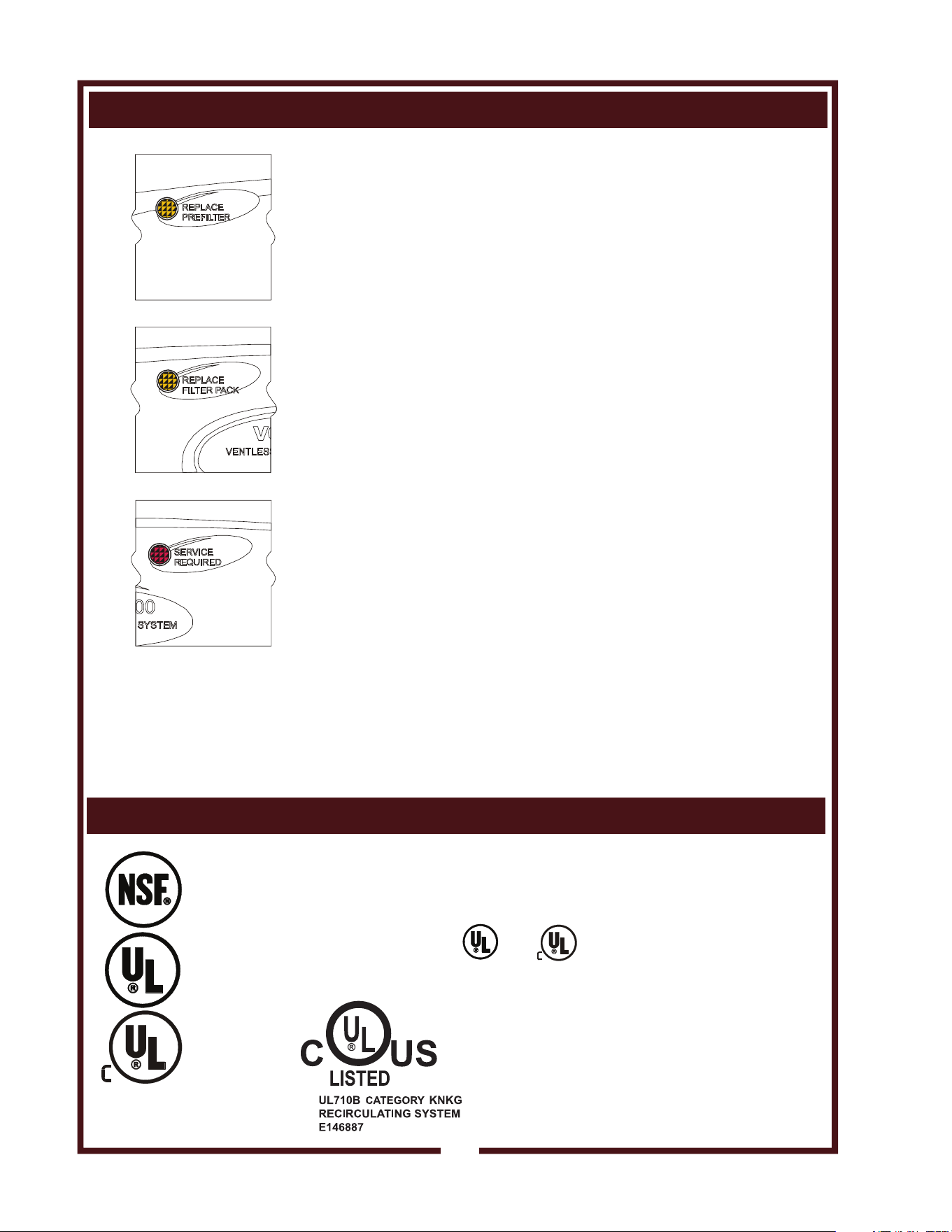
REPLACE PREFILTER and REPLACE FILTER PACK indicator lights
provide a timely warning that a system shut-down is imminent.
The actual time between the indicator light coming on and the loss of
cooking appliance power will depend upon the cooking conditions.
Anytime a dirty PRE-FILTER is replaced, the system airflow will
increase. If the condition of the FILTER PACK is marginal, the
REPLACE FILTER PACK light could then come on. If this happens,
a fresh FILTER PACK must be installed within a reasonably short time.
Loss of airflow through the old filter pack will soon cause a system
shut-down when the airflow falls below minimum vapor capture levels.
KEEP SPARE FILTER PACKS ON HAND.
IMPORTANT: If you decide to “get the most” out of the old filter pack,
and continue to use it until a system shut-down happens, it is advisable
to have a fresh filter pack readily at hand, and have someone available
who is capable of replacing it. Otherwise, you may experience an
extended down time, with consequent associated loss of business.
Use only genuine Wells replacement parts and filters, call (314) 678-
6314 or your authorized Wells service agent. Parts supplied by others
will void your warranty and may not provide safe operation.
The manufacturer assumes no liability for loss of business due to
a system shutdown caused by a dirty pre-filter and/or filter pack
(i.e. red SERVICE REQUIRED light is on), when the user fails to
have the proper replacement pre-filter and/or filter pack on hand.
The Ventless Cooking System™ hood is designed as part of a WELLS
cooking appliance only. No other use of this product is authorized by
the manufacturer or its agents. Wells Mfg. assumes no liability for the
use of this equipment with products by any other manufacturer’s, or for
use of this equipment with any Wells Manufacturing product other than
in factory certified applications.
This appliance conforms to NSF Standard 4 for sanitation only if
installed in accordance with the supplied Installation Instructions
And operated and maintained in accordance with the instructions
in this manual.
This appliance is and Listed under UL File E146882.
PRECAUTIONS AND GENERAL INFORMATION (continued)
Fig. 5 Ventilator
Warning
Indicators
10
E146882
M507 p/n 2M-304446 Owners Manual WV-FG
11
INSTALLATION
NOTE: DO NOT discard
the carton or other packing
materials until you have
inspected the appliance for
hidden damage and tested it
for proper operation.
Refer to SHIPPING DAMAGE
CLAIM PROCEDURE on the
inside front cover of this
manual.
WARNING:
RISK OF
INJURY
Installation procedures must
be performed by a qualified
technician with full knowledge
of all applicable electrical
codes. Failure can result in
personal injury and property
damage.
WARNING:
FIRE HAZARD
Avoid storing flammable or
combustible materials near
the appliance.
IMPORTANT:
This appliance requires a
minimum of 8 ft (96”) (floor
to overhead) to allow for
adequate exhaust.
Provided 6" side spacers (item
58) must be installed on the
appliance.
Factory installed side shields
(item 57) are required.
IMPORTANT:
If a remote manual pull
station is to be installed,
replace the rear casters
with legs.
UNPACKING & INSPECTION
Carefully remove the appliance from the carton. Remove all
protective plastic film, packing materials and accessories from the
Appliance before connecting electrical power or otherwise performing
any installation procedure.
Carefully read all instructions in this manual and the Installation
Instruction Sheet packed with the appliance before starting any
installation.
Read and understand all labels and diagrams attached to the
appliance.
Carefully account for all components and accessories before
discarding packing materials. Store these components in or near the
appliance for later use. These items must be installed before operating
the appliance.
1 ea. FIRE SUPPRESSION AGENT (ANSULEX® Low pH, 1.5 GAL.)
See Material Safety Data Sheet, page 28.
1 ea. FIRE SUPPRESSION MEDIA TANK
1 ea. FIRE SUPPRESSION TANK CHARGING CARTRIDGE
1 ea. GREASE BAFFLE
1 ea. FILTER PACK ASSEMBLY
1 ea. PRE-FILTER HOLDER with PRE-FILTER
1 ea. GREASE DRIP TRAY
1 ea. GREASE DRAWER ASSY FOR GRIDDLE
2 ea. 6” SIDE SPACERS
1 ea. LITERATURE PACKAGE
Additionally:
1 ea. GRIDDLE SPLASH SHIELD
1 ea. FRYER FRYPOT
2 ea. FRYER BASKETS, 1/2 SIZE
2 ea. DRAWER PANS (if unit has optional drawer warmers)
SETUP
Setup the appliance only on a firm level surface. Non-combustible
material is recommended.
Refer to the Installation Instruction Sheet for required clearances.
Maintain required clearances between the appliance and adjacent
combustible surfaces. Verify 6” left and right side clearances to
combustible construction. This appliance requires a minimum of 8 ft
(96”) (floor to overhead) to allow for adequate exhaust.
Verify that the VENTILATOR HOOD ASSEMBLY is properly and
securely assembled to the cooking appliance before beginning the
installation procedure.
If a remote manual pull station is to be installed, replace the rear
casters with legs.
Level the unit after it is in its final position. Using a spirit level, verify
that the unit is level front-to-back and side-to-side.
M507 p/n 2M-304446 Owners Manual WV-FG
SERVICE TECHNICIAN INSTALLATION NOTES
An Ansul® technician must charge and arm the fire suppression system
before the ventilator blower will operate. See page 13.
Installation and start up must be performed by an Authorized
Installation Company.
Installer must complete the WARRANTY REGISTRATION form, and
record appliance installation particulars on the CUSTOMER SERVICE
DATA form in this manual.
Certain codes require cooking equipment to be restrained with a
RESTRAINT DEVICE. It is the RESPONSIBILITY OF THE
INSTALLER to check with the AUTHORITY HAVING JURISDICTION,
in order to ascertain the applicability of this requirement to THIS
SPECIFIC EQUIPMENT INSTALLATION. Any restraint device must
allow access to the back and sides of the unit to provide for servicing
and maintenance, and must not interfere with the operation of the FIRE
SUPPRESSION SYSTEM.
ELECTRICAL INSTALLATION
1. This appliance must be installed by a licensed electrician in
accordance with all applicable codes and ordinances.
Electrical connection terminal block and ground lug are accessible
by removing the right side panel.
2. Refer to the nameplate on right side of the appliance. Verify the
ELECTRICAL SERVICE POWER. Voltage and phase must match
the nameplate specifications, and available electrical service
amperage must meet or exceed the specifications listed on page 1.
Wiring must be no less than 6 AWG solid copper wire, rated for at
least 90ºC.
NOTE: Wire gauge, insulation type and temperature rating , as
well as type, size and construction of conduit, must meet or exceed
applicable specifications of local codes and of the National
Electrical Code.
NOTE: This appliance requires a NEMA 15-60R receptacle.
3. This appliance must be connected to a suitable building ground.
The equipment ground connection is marked " ".
4. The appliance is shipped from the factory wired for 3Ø electrical
service. Refer to the Wiring Diagram included with this appliance,
and verify that field wiring conforms to this diagram.
IMPORTANT: This appliance is not approved for 1Ø operation.
Conversion of this appliance to single-phase operation will void the
warranty.
IMPORTANT!
Verify that this VENTILATOR
and food cooking equipment
installation is in compliance
with the specifications listed
in this manual, with local
code requirements, and in
accordance with N.F.P.A 96
(THE STANDARD FOR
VENTILATION CONTROL
AND FIRE PROTECTION
OF COMMERCIAL
COOKING OPERATIONS -
current edition).
THIS IS THE
RESPONSIBILITY
OF THE INSTALLER
DANGER
ELECTRIC
SHOCK
HAZARD
ELECTRIC CONNECTIONS
MUST BE MADE BY A
LICENSED ELECTRICIAN
Electrical shock will cause
death or serious injury.
CAUTION:
ELECTRIC SHOCK
HAZARD
The ground lug of this
appliance must be connected
to a suitable building ground.
NOTE: This appliance
requires a dedicated 60 Amp
electrical branch circuit
protection.
IMPORTANT:
Contact a licensed electrician
to install and connect
electrical power to the
appliance.
IMPORTANT:
Damage due to being
connected to the wrong
voltage or phase is NOT
covered by warranty.
INSTALLATION (continued)
12
M507 p/n 2M-304446 Owners Manual WV-FG
INSTALLATION (continued)
13
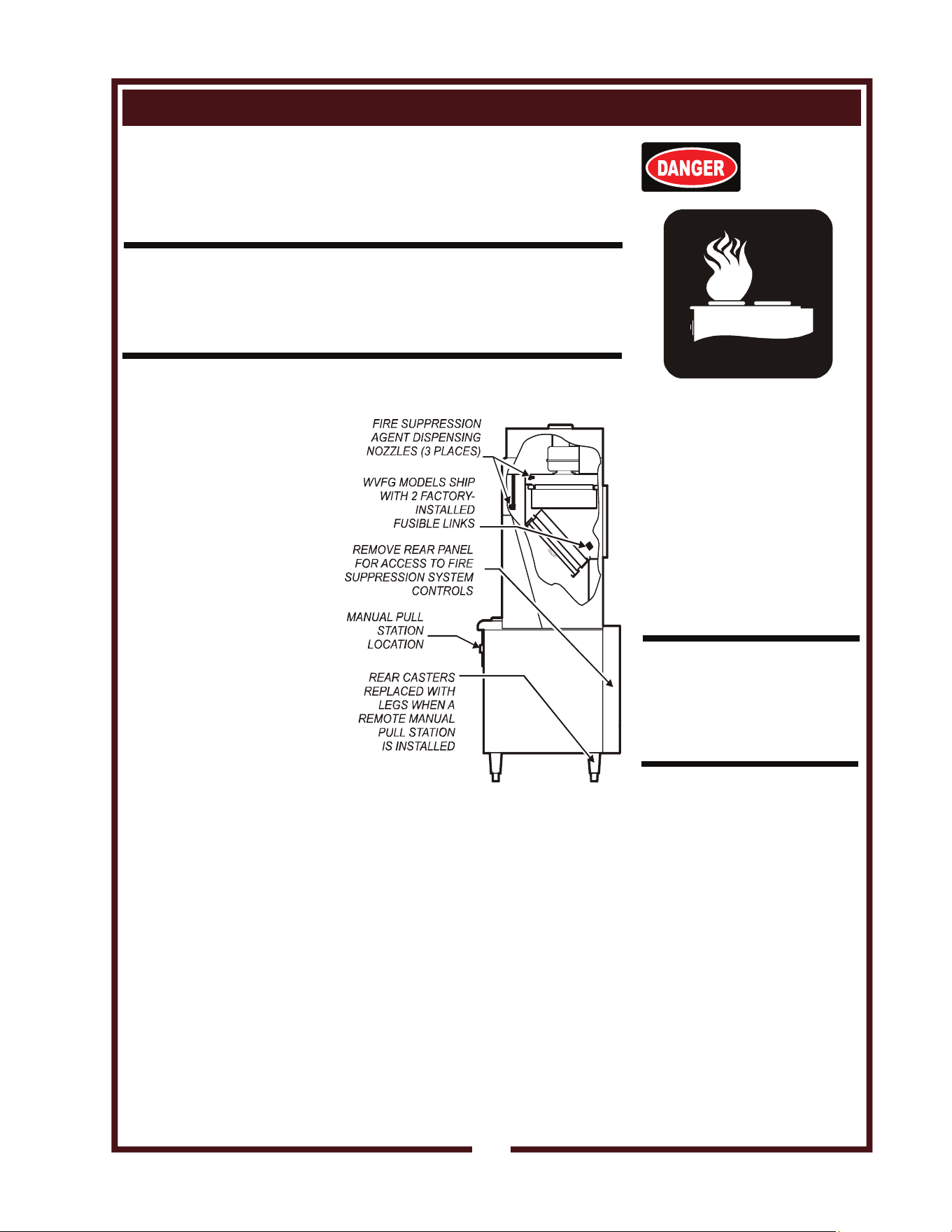
FIRE SUPPRESSION SYSTEM INSTALLATION
1. Any REMOTE MANUAL PULL STATION must be installed by an
authorized ANSUL® distributor in accordance with the
AUTHORITY HAVING JURISDICTION.
NOTE: If a REMOTE MANUAL PULL STATION is installed, moving
the unit for servicing will cause the Ansul® system to discharge. In
this case, the unit must only be installed with four fixed legs
(i.e. remove rear casters and replace with legs). Additional legs may
be ordered through an Authorized Wells Service Agency. See page 29.
2. The FIRE SUPPRESSION SYSTEM is comprised of a
pressurized cartridge &
container of liquid fire
suppressant, with
associated plumbing and
controls. It utilizes factory
installed FUSIBLE LINKS
for automatic actuation,
and a factory installed
MANUAL PULL STATION
for manual actuation.
Two NOZZLES are used
to disperse the liquid fire
suppression media.
3. When the fire suppression
system activates, the fire
suppression media is
discharged, both the
cooking appliance and the
ventilator are de-energized,
and a buzzer will sound
continuously.
The fire suppression media
will form an emulsion
designed to both smother
and cool the fire.
Call your Authorized Ansul® Distributor immediately for
service.
NOTE: See page 28
for the Material Safety Data Sheet for the fire
suppression agent.
4. The MANUAL PULL STATION and any similar REMOTE MANUAL
PULL STATION will activate the fire suppression system when the
ring on the pull station is pulled horizontally.
DANGER
FIRE
HAZARD
THE FIRE SUPPRESSION
SYSTEM MUST BE
CHARGED AND CERTIFIED
BY AN AUTHORIZED
ANSUL® DISTRIBUTOR.
NEVER ATTEMPT TO
MODIFY OR BYPASS THE
FIRE SUPPRESSION
SYSTEM.
AN UNCONTROLLED FIRE
CAN CAUSE SERIOUS
INJURY, DEATH AND/OR
PROPERTY LOSS.
IMPORTANT: The FIRE
SUPPRESSION SYSTEM
must be SET-UP and
CHARGED by an authorized
Ansul® distributor before the
ventilator blower will operate.
NOTE: If the fire suppression
system is discharged, a
buzzer will sound
continuously and the cooking
appliance will remain
inoperable until the fire
suppression system is
serviced. Recharging and
resetting must be
performed by an authorized
Ansul® distributor ONLY.
Charging of the Ansul Fire
Suppression system must be
in accordance with Ansul®
Design, Installation, Recharge
and Maintenance Manual.
(Ansul® #418087-05)
Fig. 6 Fire Suppression System
M507 p/n 2M-304446 Owners Manual WV-FG
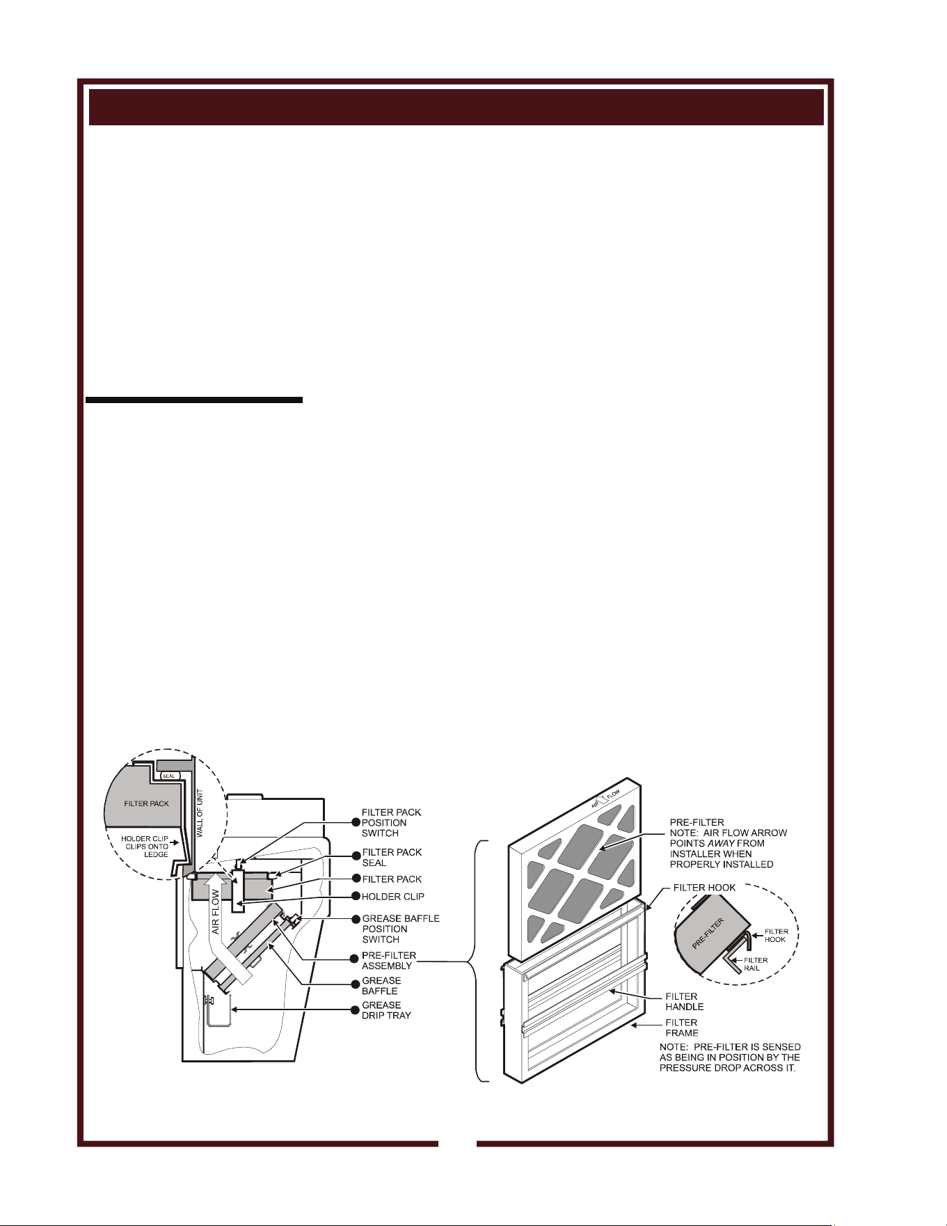
FILTERS INSTALLATION
1. FILTER PACK: Ships installed in the hood. If the FILTER PACK is
not in position, the CHECK FILTERS indicator will light.
If the FILTER PACK becomes clogged, the REPLACE FILTER
PACK indicator will glow.
To install the FILTER PACK: Position the filter pack with the
charcoal portion UP. Slide the filter pack toward the rear of the unit
until it contacts the guides on the back panel. Push the filter pack
UP into the upper opening until it rests firmly against the filter pack
seal. When up in position, holder clips can be snapped over wall
ledge on each side. To remove FILTER PACK: Grasp both holder
clips and pull INWARD until the clips clear the sidewall ledge. Then,
pull the filter pack down and out.
2. PRE-FILTER: The PRE-FILTER ships in the FILTER FRAME. If
the PRE-FILTER is not in position, or if the PRE-FILTER is not in
the FILTER FRAME, the CHECK FILTERS indicator will light. If the
PRE-FILTER becomes clogged, the REPLACE PRE-FILTER
indicator will glow.
To install the PRE-FILTER: Pay attention to the air flow markings.
The AIR FLOW arrow will point away from the installer. Slide the
assembly up into the front opening, behind the upper filter rail.
While pressing slightly against the bottom of the assembly, pull the
FILTER HANDLE toward you so as to engage the FILTER HOOK
over the lip of the top filter rail. Then lower and seat the assembly
into the top indentation of the lower filter rail.
3. GREASE BAFFLE: If the GREASE BAFFLE is not in place, the
CHECK FILTERS indicator will glow.
To install the GREASE BAFFLE: Slide the grease baffle up into the
indentation of the upper filter rail, then lower and seat it into the
bottom indentation of the lower filter rail. Pull toward you and
downward to verify the GREASE BAFFLE is properly seated in the
lower frame rail.
NOTE:
The GREASE BAFFLE and
FILTER PACK activate
mechanical switches, and the
PRE-FILTER activates a
vacuum switch, to verify that
the filter elements are in their
proper positions.
All filter elements must be
properly installed or the
cooking appliances will not
be energized. Also, the
CHECK FILTERS indicator
will light.
IMPORTANT:
The filter hook prevents the
PRE-FILTER from being
drawn in during operation.
After installation, press
against the top of the filter
frame to verify proper
engagement of the filter hook
over the lip of the top filter
rail.
INSTALLATION (continued)
Fig. 7 Filter Installation
14
M507 p/n 2M-304446 Owners Manual WV-FG
INSTALLATION (continued)
15
CAUTION:
BURN HAZARD
DO NOT OPERATE UNLESS
THE GREASE DRIP TRAY
IS INSTALLED.
Moisture will drip into the hot
cooking surface causing
splattering of hot liquids.
Serious injury can result from
contact with hot splatter.
GREASE DRIP TRAY INSTALLATION
1. Install the GREASE DRIP TRAY on the hanger brackets, directly
below the grease baffle.
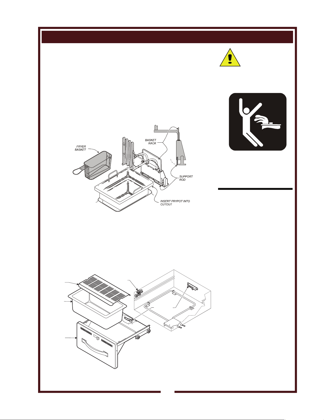
INSTALL COOKING APPLIANCE COMPONENTS
1. FRYER COMPONENTS
a. Raise the fryer ELEMENT HEAD and install FRYPOT.
b. Using the BASKET RACK as a handle, lift the ELEMENT HEAD
slightly, Then rotate the spring-loaded SUPPORT ROD forward.
Lower the ELEMENT HEAD into the FRYPOT.
c. Hang the FRYER BASKETS on the BASKET RACK.
2. If appliance is equipped with the optional warmer drawers:
a. Be sure roller catches (inside warmer cavity) are in the open
position. Install drawer assemblies in drawer slides.
b. Place appropriate one drawer insert pan into each warmer
drawer.
c. If used, place one Humitrol rack into each drawer pan.
Fig. 8 Fryer Component Installation
Fig. 9 Roll Warmer Drawer Pan Installation
OPTIONAL
HUMITROL
RACK
PRODUCT
PAN
DRAWER
ASSEMBLY
LATCH
ASSEMBLY
DRAWER
STOP
M507 p/n 2M-304446 Owners Manual WV-FG
OPERATION
CAUTION:
HOT SURFACE
Exposed surfaces can be hot
to the touch and may cause
burns.
VENTILATOR OPERATION
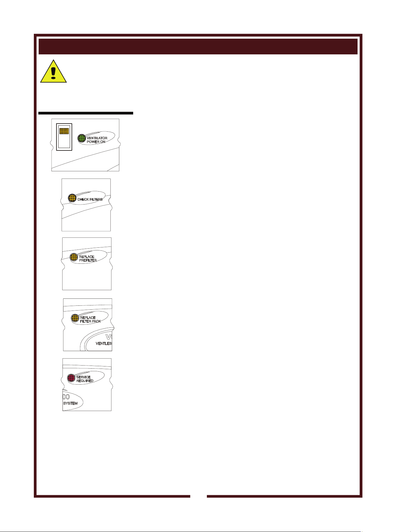
1. Press the VENTILATOR POWER switch to ON. The green
VENTILATOR POWER light will glow and the blower fan will start.
After a short time, if all filters are sensed as being in position and
not clogged, the cooking appliance will be energized.
During normal operation, the VENTILATOR POWER light will be
the only light glowing on the upper control panel.
2. If the amber CHECK FILTER light glows, one or more filter
elements is out of position. Check the GREASE BAFFLE,
PRE-FILTER and FILTER PACK for proper installation in their
respective positions. Grease baffle and filter pack position are
sensed by mechanical switches. Pre-filter position is sensed by a
vacuum switch.
3. When the amber REPLACE PRE-FILTER light glows, the pre-filter
is nearing the end of its service life. Replace the disposable
PRE-FILTER ELEMENT.
4. When the amber REPLACE FILTER PACK light illuminates, the
HEPA / Charcoal filter pack is nearing the end of its service life.
Replace the FILTER PACK.
Note: The REPLACE PRE-FILTER and REPLACE FILTER PACK
lights are a warning that the indicated filter is near the end of its
service life. The appliance will continue to operate for a period of
time after the light glows to allow continued operation through a
peak period. However, the indicated filters must be replaced within
a reasonably short time period or they will clog and shut down
electrical power to the cooking appliance . The ventilator blower
will continue to run.
5. When the red SERVICE REQUIRED light glows, either the
pre-filter or filter pack (or both) is clogged and can no longer pass
sufficient air to allow further operation. The ventilator fan continues
to run, but the cooking appliance is shut down until the underlying
clogged filter situation has been corrected. This can occur when
neither CHANGE...FILTER indicator light is lit, if both pre-filter and
filter pack are marginal. Replacing both the pre-filter and the filter
pack will remedy the situation.
Note: Replacing the pre-filter, even though not very dirty, will often
extend the service life of the more expensive filter pack.
Reset the unit by turning the VENTILATOR POWER switch to
OFF, then back ON.
6. A failure of incoming electrical power will cause a shut down of the
unit. After power is restored, reset the unit by turning the
VENTILATOR POWER switch to OFF, then back ON.
NOTE: Griddle and fryer will not operate unless the fire suppression
system is charged, and the ventilator section is operating .
Fig. 10 Ventilator Indicator
and Warning Lights
16
M507 p/n 2M-304446 Owners Manual WV-FG

OPERATION (continued)
17
GRIDDLE OPERATION
PREPARING THE GRIDDLE SURFACE
1. SEASONING STANDARD GRIDDLES
As manufactured, the steel surface of your Wells griddle has
microscopic pores. It is important to fill these pores with oil in order
to provide a hard, non-stick cooking surface.
a. Preheat the griddle surface to 375ºF (191ºC).
b. Spread a light film of cooking oil over the entire griddle surface
c. Allow the oil film to cook in for approximately 2 minutes, or until
it smokes.
d. Wipe the griddle surface with a clean damp cloth until all oil is
removed.
e. For new griddles, repeat this procedure 2-3 times until the
griddle has a slick, clean surface.
2. CHROME PLATED GRIDDLES
Because the microscopic pores in the griddle surface are filled by
the chrome plating, no seasoning of the griddle surface is required.
a. Thoroughly clean the griddle surface using a soft clean cloth
and a small amount of mild detergent.
b. Rinse and dry thoroughly after cleaning.
c. The griddle is now ready to use.
USING THE GRIDDLE
1. Turn the temperature control knob to the desired temperature.
The indicator light will glow while the griddle is heating. When the
indicator light first goes out, the griddle is ready to use.
2. For standard griddles, keep the griddle surface clean and well oiled
during use. Scrape cooking waste into the grease tray frequently
during use. Occasionally brush or spray a light coat of cooking oil
on the griddle surface in order to maintain the non-stick surface.
3. For chrome plated griddles, scrape cooking waste into the grease
tray after preparing each order.
DO NOT bang or tap pots, pans, spatulas or other metal utensils on
the griddle surface as this may damage the chrome plating.
CAUTION:
HOT SURFACE
Exposed surfaces can be hot
to the touch and may cause
burns.
NOTE:
Standard griddles must be
seasoned after every cleaning.
IMPORTANT:
SCRATCHES WILL DAMAGE
THE GRIDDLE SURFACE!
DO NOT use anything on this
griddle that could scratch the
surface.
DO NOT clean chrome surface
with griddle bricks, pumice
stone or abrasive cleansers.
DO NOT bang or tap pots,
pans, spatulas or other metal
utensils on the griddle surface
as this may damage the
chrome plating.
M507 p/n 2M-304446 Owners Manual WV-FG
OPERATION
18
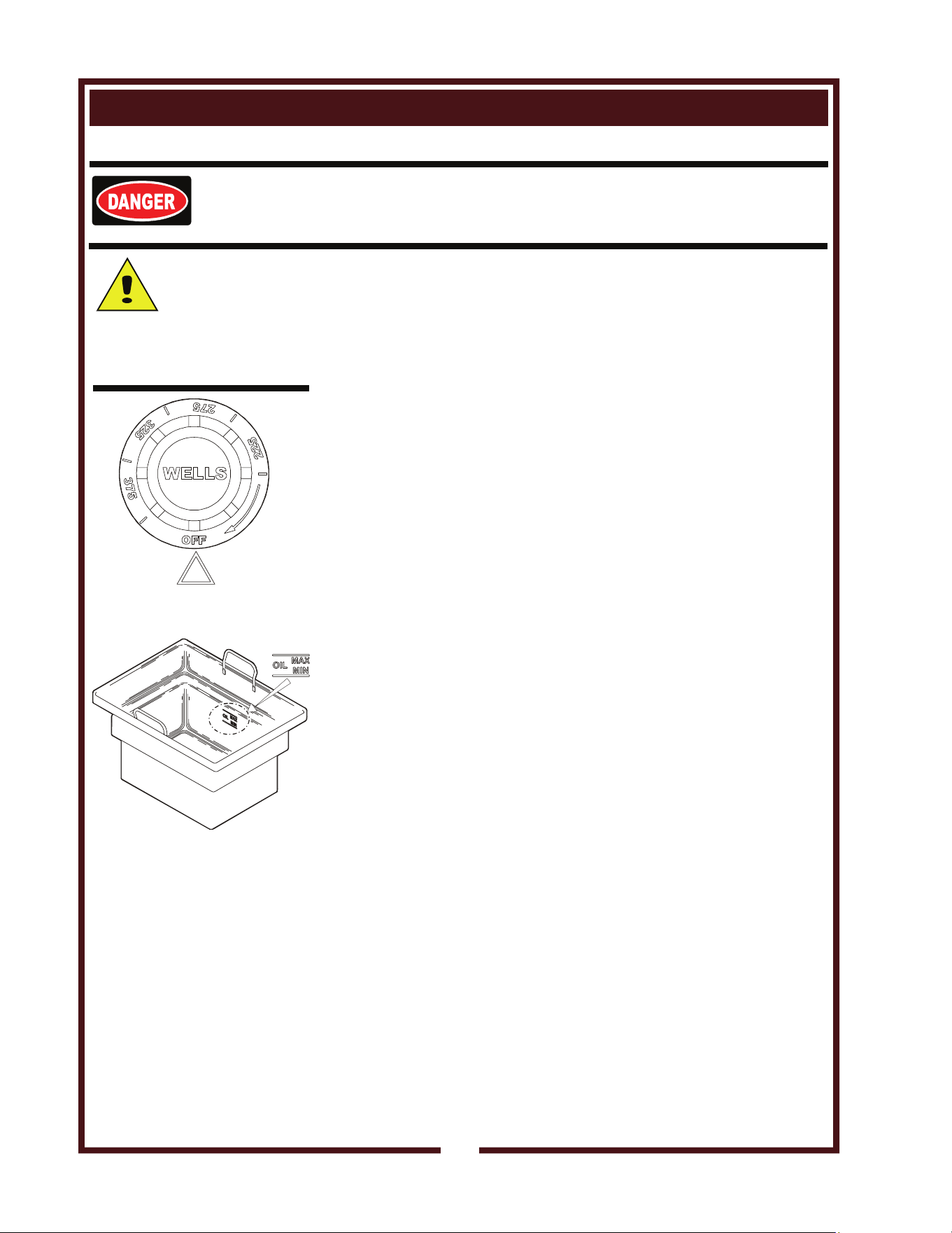
1. a. Be sure the TEMPERATURE CONTROL KNOB is turned to
OFF.
b. Lower the ELEMENT HEAD into the frypot by pushing back on
the BASKET SUPPORT ROD, raising the ELEMENT HEAD
SUPPORT ROD, then carefully lowering the elements.
2. Fill the FRYPOT with commercial-grade liquid shortening to the
MIN OIL line.
Capacity: 15 pounds
IMPORTANT: DO NOT overfill the frypot. Cold oil will expand as it
heats. Adding too much oil will allow the frypot to overflow during
operation.
For best results, always use top grade commercial shortening made
specially for frying. Maintain proper oil level in frypot during
operation.
3. Turn the TEMPERATURE CONTROL KNOB to the desired
temperature. The HEAT INDICATOR will glow. When the oil
reaches the desired temperature, the heat indicator will go out. The
heat indicator will go off and on during operation as the thermostat
cycles to maintain temperature.
For best results: DO NOT set temperature control to a temperature
setting higher than is required for the food product.
4. Load either or both baskets no more than 1/2 full with food product.
a. DO NOT overload fry baskets. For best results, load baskets
uniformly to half full.
b. Using the basket handle, lower the baskets into the hot oil.
c. When food is cooked, lift the basket out of the oil by the handle.
Hang the baskets on the BASKET SUPPORT ROD to drain.
5. When the heat indicator light cycles off, the fryer is ready to cook
the next load.
6. Reduce temperature control to 225ºF during idle periods to save
power and extend the life of the oil. The fryer will return to
operating temperature in just a few minutes when needed.
7. Keep the fryer clean at all times. Rinse baskets frequently, and dry
thoroughly, in order to prevent oil contamination.
8. Drain the frypot completely after use. Filter the oil daily, or more
often during heavy use.
FRYER OPERATION
DANGER: BURN HAZARD
Contact with hot oil will cause severe burns.
Always wear protective clothing and heat resistant gloves when operating the fryer.
CAUTION:
HOT SURFACE
Exposed surfaces can be hot
to the touch and may cause
burns.
Fig. 3 Temperature Control
Knob
Fig. 4 Oil Level Marking
NOTE: If the oil exceeds a
safe temperature, the hi-limit
safety will shut down the unit
and light the red TROUBLE
indicator.
To reset:
Allow the oil to cool, then
press the red button on the
back of the element head
until it “clicks” and stays in.
If tripping persists, see
Troubleshooting Suggestions,
page 26.
M507 p/n 2M-304446 Owners Manual WV-FG
OPERATION (continued)
19
CAUTION:
HOT SURFACE
Exposed surfaces
can be hot to the touch
and may cause burns.
NOTE:
The chart below is intended
as a guide ONLY. Your own
experience with this
appliance, type of foods and
method of operation will
enable you to determine the
temperature control and air
vent settings best suited to
your operation.
DRAWER WARMER OPERATION (when provided)
HEATING OPTIONS
1. Moist heat with Humitrol Rack:
a. MOIST operation prevents food from drying out as moisture, as
well as heat, is applied to the warming chamber.
b. To set for MOIST operation, remove Humitrol Rack from
bottom of drawer insert pan and carefully pour approximately
2 quarts of water (½” depth) into the pan. Reinstall rack.
c. The Humitrol Rack decreases the sloshing effect of the water
in the pan when the drawer is opened. When the drawer is
closed, the Humitrol Rack allows steam to rise through the
stored product in the drawer.
d. Place the food directly on the rack. The rack is designed to
support the food off of the steam vents, where water droplets
may form.
e. Check the water level in the pan periodically, and add water
when necessary.
f. Set the front air vent between fully closed and half-open.
Actual setting will depend upon the type and amount of product
stored in the drawer, the temperature setting, and the
frequency with which the drawer is opened.
2. Moist heat with pans:
a. This Wells warmer is designed to accommodate any
combination of standard-size, steam table pans.
b. Place a small amount of water in drawer pan. Place pans in
drawer pan.
c. Check the water level in the pan periodically, and add water
when necessary.
3. Dry heat:
For some applications, you may want to store previously
prepared foods in a dry-heat environment. To do so, place the
food directly into the empty (i.e. no water) drawer pan.
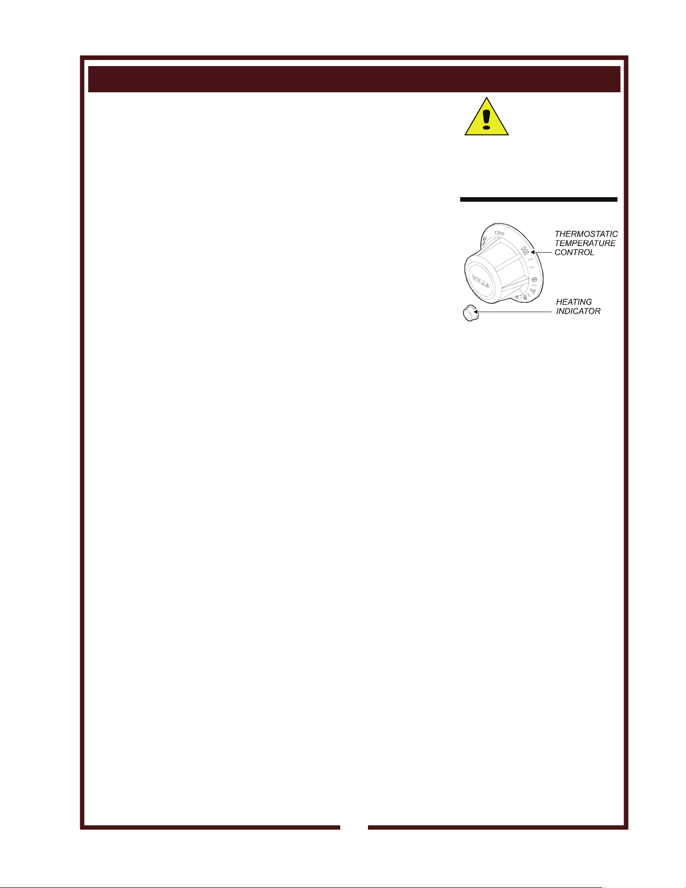
Fig. 9 Roll Warmer
Temperature Control
PRODUCT RECOMMENDED TYPE CONTROL AIR VENT
TYPE STORAGE TEMP. OF HEAT SETTING SETTING
Hard Rolls 160-185ºF Dry 7-8 Closed
Soft Rolls 150-175ºF Moist 6-7 Open - ½
Vegetables 175-185ºF Moist 7-8 Open - ½
Meats 165-185ºF Dry 6-8 Closed
Fish 165-185ºF Moist 6-8 Open
Casseroles 150-175ºF Dry 6-7 Closed
Pies, Desserts 160-185ºF Dry 6-7 Closed
Nachos 150-170ºF Dry do not put water 4-6 Full Open
Corn Chips 150-170ºF Dry in the pan 4-6 Full Open
OPERATING CHART FOR DRAWER WARMERS
<
M507 p/n 2M-304446 Owners Manual WV-FG
OPERATION (continued)
20
ºF
ºC
LOAD
PROCESS
32
5
1
4
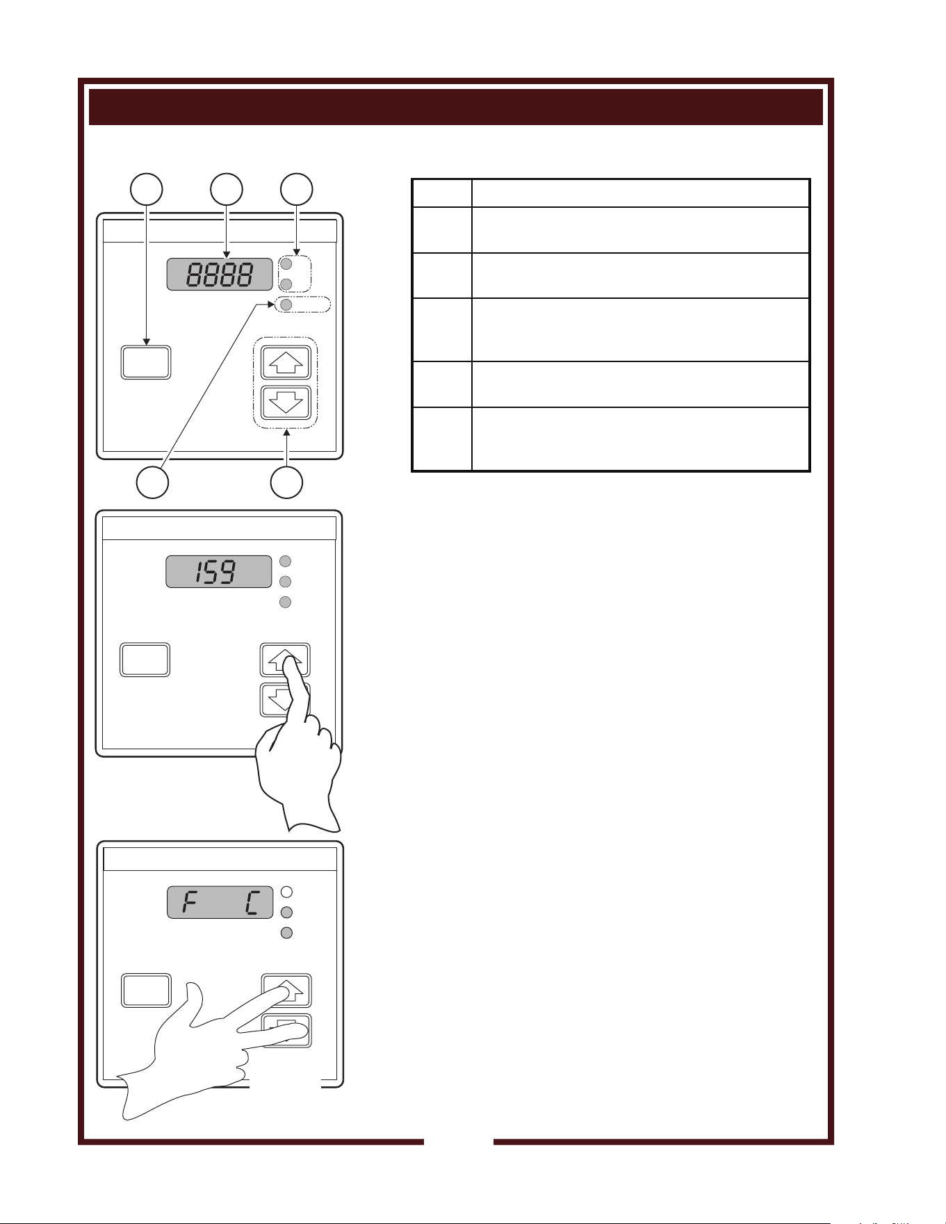
RWT- CONTROL MODULE
SET SETPOINT TEMPERATURE
Press an arrow key:
UP arrow to increase
DOWN arrow to decrease
Release key when desired setpoint temperature
is displayed.
Reading is locked into memory 3 seconds after
last key stroke.
Minimum setpoint is 140ºF (60ºC)
Maximum setpoint is 250ºF (121ºC)
CHANGE DISPLAY MODE ( ºF or ºC)
Press and hold UP arrow and DOWN arrow keys
for 10 seconds.
Release keys when display reads F C.
Within 3 seconds, press UP arrow or DOWN arrow
key until desired indicator (ºF or ºC) glows.
The new value will lock into memory 3 seconds
after last keystroke.
PROCESS
ºF
ºC
LOAD
ºF
ºC
LOAD
HOLD
10 SEC.
PROCESS
ITEM DESCRIPTION
1
PROCESS Key:
Press to view actual temperature of cavity.
2
4 Character LED Display:
Normally shows SETPOINT temperature.
3
ºF or ºC Indicator:
Glows to indicate if unit is configured for
degrees Fahrenheit or degrees Celsius.
4
LOAD Indicator:
Glows when heating element is energized.
5
Increment and Decrement Keys:
Press UP arrow to increase
Press DOWN arrow to decrease
DRAWER WARMER OPERATION (when provided)
M507 p/n 2M-304446 Owners Manual WV-FG

21
CLEANING INSTRUCTIONS
DRAWER WARMER CLEANING INSTRUCTIONS
PRECAUTIONS: Turn control knob to OFF.
Allow drawers to cool before proceeding.
Remove drawer pans and Humitrol racks.
FREQUENCY: Minimum -Daily
TOOLS: Warm water and mild detergent
Clean cloth or sponge
1. Remove drawers from warmer:
a. Pull warmer drawer out until fully extended.
b. Slide finger along left and right slide rail until you reach the
latches (located at the front end of the cabinet-mounted rails)
Press down on both left and right latch.
c. Pull drawer away from warmer.
2. Clean drawers, drawer pans, Humitrol Racks and/or insets with
warm water and mild detergent.
Rinse all components thoroughly with clear water.
Dry all components prior to reinstalling them in warmer.
3. Sweep crumbs and other debris from warmer cavity.
4. Clean the outside of the unit by wiping with a clean cloth or
sponge, warm water and mild detergent. Dry with a clean cloth,
then wipe with a polish formulated for stainless steel.
5. It is important to keep the slide rails clear and free from debris.
Periodic cleaning of the slide rails and other adjoining parts is
necessary to assure smooth drawer operation.
6. Check drawer rollers. Be sure they roll freely and that the slide
rails are free from debris.
7. Be sure cabinet-mounted drawer catch roller is “up”, then re-
install drawers.
CAUTION:
ELECTRIC
SHOCK HAZARD
Disconnect appliance from
electric power before cleaning.
CAUTION:
HOT SURFACE
Exposed surfaces
can be hot to the touch
and may cause burns.
Allow appliance to cool before
cleaning.
M507 p/n 2M-304446 Owners Manual WV-FG
22
CLEANING INSTRUCTIONS (continued)
VENTILATOR WEEKLY CLEANING
PREPARATION: Disconnect appliance from electric power
Allow to cool before cleaning
FREQUENCY: Weekly
TOOLS: Warm water and a mild detergent
Soft clean cloth or sponge
Bristle brush
Container for disposal of grease
1. Remove the grease baffle, pre-filter assembly, grease trough and
grease cup. Empty the grease trough and grease cup.
2. Remove the pre-filter from the filter frame. Wash and rinse the
filter frame ONLY.
3. Wash and rinse the grease baffle, grease trough and grease cup in
a sink or dishwasher using mild detergent and warm water. Allow
to air dry.
4. Reinsert the pre-filter into the filter frame. Reinstall the pre-filter,
grease baffle, grease trough and grease cup.
Procedure is complete
CAUTION:
ELECTRIC
SHOCK HAZARD
Disconnect appliance from
electric power before
cleaning.
CAUTION:
HOT SURFACE
Exposed surfaces
can be hot to the touch
and may cause burns. Allow
appliance to cool before
cleaning.
IMPORTANT:
Never allow PRE-FILTER or
FILTER PACK to get wet.
DO NOT wash either of these
two filters. Washing these
filters will ruin them and cause
the appliance to shut-down.
IMPORTANT:
DO NOT spill or pour water
into controls, control panel,
wiring or coil-type hotplate
elements. Damage to internal
components will occur.
Damage to internal
components from water
damage is not covered by
warranty.
IMPORTANT:
DO NOT use steel wool or
metal implements to clean
cabinet surfaces.
M507 p/n 2M-304446 Owners Manual WV-FG
CLEANING INSTRUCTIONS (continued)
23
CAUTION:
ELECTRIC
SHOCK HAZARD
Disconnect appliance from
electric power before
cleaning.
CAUTION:
HOT SURFACE
Exposed surfaces
can be hot to the touch
and may cause burns. Allow
appliance to cool before
cleaning.
IMPORTANT:
Never allow PRE-FILTER or
FILTER PACK to get wet.
DO NOT wash either of these
two filters. Washing these
filters will ruin them and cause
the appliance to shut-down.
IMPORTANT:
DO NOT spill or pour water
into controls, control panel,
wiring or coil-type hotplate
elements. Damage to internal
components will occur.
Damage to internal
components from water
damage is not covered by
warranty.
IMPORTANT:
DO NOT use steel wool or
metal implements to clean
cabinet surfaces.
VENTILATOR MONTHLY CLEANING
PREPARATION: Disconnect appliance from electric power
Allow to cool before cleaning
FREQUENCY: Monthly
TOOLS: Warm water and a mild detergent
Soft clean cloth or sponge
Plastic scouring pad, plastic scraper
Container for disposal of grease
EXTERIOR
Wash exterior surfaces with a soft clean cloth or sponge dampened
with warm water, mild soap or detergent. Rinse with a soft clean
cloth or sponge dampened with warm water. Allow to air dry.
INTERIOR:
In addition to the weekly cleaning procedure, remove the filter
pack.
Cover the griddle section. Wash the interior surfaces of the
ventilator with warm water, mild soap or detergent and a clean,
soft cloth or sponge. Stubborn or burned-on food debris bay be
removed with a plastic scouring pad or plastic scraper.
Dry thoroughly with a clean soft cloth.
Uncover the griddle and reassemble the ventilator.
Procedure is complete.
M507 p/n 2M-304446 Owners Manual WV-FG
24
CLEANING INSTRUCTIONS (continued)
GRIDDLE CLEANING INSTRUCTIONS
PRECAUTIONS Griddle surfaces are HOT. Wear appropriate heat
protective gloves, apron and goggles
FREQUENCY As Noted
TOOLS Scraper, Pumice Stone or Griddle Brick
Clean Cooking Oil
Mild Detergent, Soft Cloth or Sponge
Plastic Scouring Pad
1. To keep the griddle clean and food flavors at their best, scrape the
griddle after preparing each order. Scrape excess food into the
waste hole in the grease trough (front of the griddle cooking
surface). After each 2 - 3 orders, wipe the griddle surface with a
light coat of oil.
2. Clean the griddle surface daily, at a minimum:
a. Keep the ventilator fan
ON.
b. Set griddle temperature control to 220ºF. Allow the griddle
temperature to drop to 220ºF before proceeding.
c. Pour a small amount of water on the griddle surface and let it
"sizzle".
d. Use a pumice stone or griddle brick to remove all remaining
waste, and to clean the griddle surface down to bright metal.
Wipe off any remaining powder residue.
e. Use a soft-bristled fiber brush in a circular motion to remove any
remaining food particles.
f. Turn temperature control to OFF. Allow the griddle surface to
cool, then wipe the surface with a clean cloth.
g. Dry the griddle surface thoroughly.
h. Season the cooking surface after each cleaning using the
instructions on page 10.
3. At least once each day, the GREASE TROUGH must be
thoroughly cleaned. Using a scraper, remove all grease and
food waste from the grease trough and into the grease drawer.
4. After scraping all cooking waste from grease trough into GREASE
DRAWER, take the grease drawer to kitchen cleaning area and
properly dispose of all waste.
a. Clean drawer with hot water and a mild detergent.
b. Dry drawer thoroughly and reinstall in griddle.
5. GRIDDLE EXTERIOR:
a. Wipe down splash guards, griddle body and the grease trough
with a cloth dampened with warm water and a mild detergent.
b. A plastic scouring pad and a non-abrasive cleanser may be
used for hard-to-remove food particles.
c. Rinse thoroughly with clean water. DO NOT splash or pour
water onto control panel or wiring.
d. Dry griddle with a soft, clean cloth.
CAUTION:
HOT SURFACE
Exposed surfaces can be hot
to the touch and may cause
burns.
CAUTION:
ELECTRIC
SHOCK HAZARD
DO NOT splash or pour water
onto control panel or wiring.
CAUTION:
HEAT AND
SMOKE HAZARD
Keep the ventilator fan running
during any "hot surface"
cleaning operation to avoid a
build-up of heat and/or smoke.
IMPORTANT: Avoid Fire
Suppression System
discharge!
Keep the ventilator fan run-
ning during any "hot sur-
face" cleaning operation to
avoid melting a fusible link and
causing a discharge of the fire
suppression media.
M507 p/n 2M-304446 Owners Manual WV-FG
25
CLEANING INSTRUCTIONS (continued)
FRYER SECTION CLEANING INSTRUCTIONS
DANGER: BURN HAZARD
Contact with hot oil will cause severe burns. Allow the fryer to cool before cleaning.
Always wear protective clothing and heat resistant gloves when cleaning the fryer.
PREPARATION Turn fryer switch and temperature control OFF
Allow fryer to cool completely before cleaning
Disconnect fryer from electric power before
cleaning
FREQUENCY Daily, or as needed
TOOLS Mild Detergent, Non-abrasive cleanser
Soft Cloth or Sponge, Plastic Scouring Pad
Container for disposal of used oil.
CLEANING
1. Turn fryer switch and temperature control OFF. Disconnect the
appliance from electric power.
2. Remove fry baskets, then swing the element head up and out of
the frypot.
NOTE: The element support rod is spring-loaded. When the
element head is raised, the support rod will automatically swing
into position to keep the element head raised.
3. Allow the oil to cool to a safe temperature (120ºF or less).
Carefully remove the frypot: wearing heat-resistant gloves, lift the
frypot by the handles. Drain the oil into a suitable container.
4. Frypot and baskets may be washed in a dishwasher, or with warm
water and mild detergent. Rinse thoroughly and dry completely.
5. Wipe/brush all crumbs, breading and cooking debris from
elements. Pay particular attention to the area between the element
and the thermobulbs. Be careful that the capillary tubes of the
thermobulbs are not moved or damaged during cleaning.
6. Keep all exterior surfaces free from splashed grease by wiping with
a clean cloth dampened with warm water and mild detergent. A
non-abrasive detergent and plastic scouring pad may be used for
stubborn deposits.
IMPORTANT: DO NOT use steel wool or abrasive cleansers
as these will damage the surface finish.
IMPORTANT: DO NOT submerge fryer in water. DO NOT spill or
pour water into controls, control panel or wiring. Damage to
internal components will occur.
7. Be certain frypot is completely dry, then reinstall in fryer.
a. Be sure the TEMPERATURE CONTROL KNOB is turned to
OFF, then plug unit into receptacle.
b. Lower the ELEMENT HEAD into the frypot by pushing back on
the ELEMENT LIFTING HANDLE, raising the SUPPORT ROD,
then carefully lowering the elements.
c. Add new or filtered oil to the MIN OIL line in frypot
Procedure is complete.
CAUTION:
ELECTRIC SHOCK
HAZARD
Disconnect fryer from electric
power before cleaning.
CAUTION:
BURN HAZARD
Allow fryer to cool completely
before cleaning.
CAUTION:
SHOCK HAZARD
Do not submerge fryer in
water.
IMPORTANT: DO NOT spill
or pour water into controls,
control panel or wiring.
DO NOT submerge fryer in
water. Damage to internal
components will occur.
Damage to internal
components from water
damage is not covered by
warranty.
IMPORTANT: DO NOT use
steel wool or abrasive
cleansers for cleaning the
fryer cabinet or frypot.
To remove carbonization from
frypot and element, see
PERIODIC CLEANING on
page 25.
IMPORTANT:
Nickel plated frypot must be
dried completely in order to
prevent rusting, and to
eliminate water contamination
of the cooking oil.
M507 p/n 2M-304446 Owners Manual WV-FG
26
MAINTENANCE INSTRUCTIONS
FRYER - DISPOSAL OF USED OIL
DANGER: BURN HAZARD
Contact with hot oil will cause severe burns. Allow the fryer to cool before cleaning.
Always wear protective clothing and heat resistant gloves when handling hot oil.
PREPARATION Turn temperature control to OFF
Allow fryer to cool completely before draining
FREQUENCY Daily, or as needed
TOOLS Container for disposal of used oil.
OIL DISPOSAL
1. Turn temperature control to OFF.
2. Allow the oil to cool to a safe temperature (120ºF or 50ºC).
3. Raise the element head and lift the frypot out of the fryer by the
frypot handles.
4. Dispose of the used oil in an approved oil disposal receptacle, or
filter the oil for reuse.
5. Wipe the frypot and reinstall in the fryer.
Procedure is complete.
CAUTION:
BURN HAZARD
Allow fryer to cool completely
before draining.
CAUTION:
SLIP AND FALL
HAZARD
Clean up oil spills
immediately. Slipping in oil
can cause injury.
CAUTION:
HEALTH
HAZARD
Clean up oil spills
immediately. Oil provides an
environment for the growth of
bacteria, which presents a
health hazard.
M507 p/n 2M-304446 Owners Manual WV-FG

27
MAINTENANCE INSTRUCTIONS (continued)
Periodic cleaning is
necessary to remove
carbonization from the
elements and frypot.
Frypot may be cleaned by
the method described at
right, or with a commercial
frypot cleaner. Be sure to
follow the manufacturer's
directions.
Before cleaning, ALWAYS:
x Disconnect the fryer
from electrical power
and allow to cool.
x Drain the oil and wipe
out the frypot.
FRYER - PERIODIC CLEANING
Empty frypot and performing cleaning procedure as described on page 21.
Add 1/2 cup of granulated dishwasher detergent to frypot. Fill with water
to the MAX OIL line.
Lower the element into the frypot and set the control knob to 225ºF
Boil the mixture for five minutes. Turn the control knob to OFF. Allow the
mixture to set in the frypot overnight.
After the soak period, raise the elements and remove any remaining
carbonization with a stiff bristle brush. Be careful that the capillary tubes
of the thermobulbs are not moved or damaged during cleaning.
Drain the frypot and wash with warm water and mild detergent.
Reinstall the frypot in the fryer. Add 1 quart of vinegar, then fill to the MAX
OIL line with cold water.
Lower the elements into the vinegar solution. Allow to set for 15 minutes.
Drain the frypot and rinse with clean water. Dry the frypot and elements
thoroughly before returning the fryer to operation.
IMPORTANT: Nickel plated frypot must be dried completely in order to
prevent rusting, and to eliminate water contamination of the cooking oil.
M507 p/n 2M-304446 Owners Manual WV-FG
CAUTION:
SHOCK HAZARD
Disconnect appliance from
electric power before cleaning.
CAUTION:
HOT SURFACE
Exposed surfaces can be hot
to the touch and may cause
burns. Allow appliance to cool
before servicing.
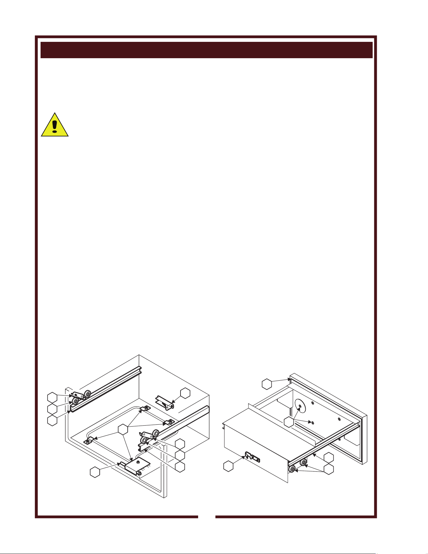
ADJUSTMENTS AND LUBRICATION
PRECAUTIONS: Turn control knob to OFF. Unplug warmer
Allow drawers to cool before proceeding.
Remove drawer pans and Humitrol racks
FREQUENCY: Minimum - monthly. Every 2 weeks recommended.
TOOLS: Screwdrivers, Phillips (+) and flat blade (-).
Nut drivers, 3/8” and 7/16”.
Food-grade lubricant.
1. Check slides on cabinet and drawers for cleanliness.
2. Check all rollers on cabinet and drawers for cleanliness and
tightness. Lubricate.
3. Check cabinet drawer stops for operation. Stops must “snap” down
positively. Clean and adjust as required.
4. Check cabinet heating element fasteners for tightness.
5. Check all cabinet drawer catches for tightness and operation.
Lubricate. Be certain roller is “out” before attempting to install
drawer.
6. Check thermostat thermobulb and capillary tube for condition.
Thermobulb must be securely mounted in the appropriate holder.
Arrange repairs for damaged thermobulb or capillary tube.
7. Check drawer faceplate and handle fasteners for tightness.
8. Check drawer catch clip for tightness.
9. For drawers equipped with gaskets, examine condition of gasket.
Arrange repairs for torn or damaged gaskets.
10. Reinstall drawers and check for proper operation.
Procedure is complete.
1
6
5
4
2
3
1
1
2
2
8
9
3
7
MAINTENANCE INSTRUCTIONS
28
M507 p/n 2M-304446 Owners Manual WV-FG
TROUBLESHOOTING SUGGESTIONS
29
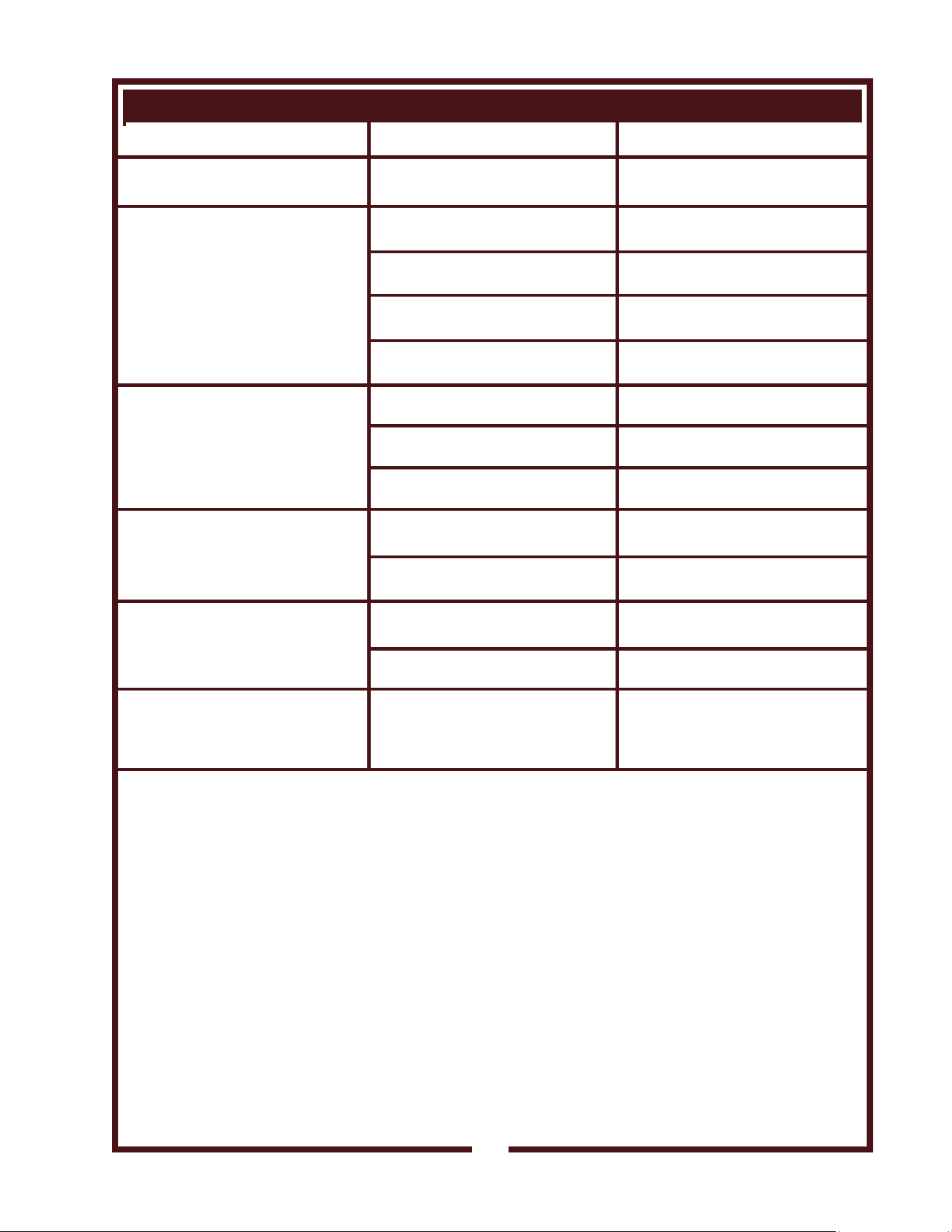
SYMPTOM POSSIBLE CAUSE RECOMMENDED REMEDY
No power to unit Not plugged in or circuit breaker
tripped
Plug unit into power receptacle
Reset circuit breaker
Cooking appliances not
energized
Filters not properly installed
(CHECK FILTERS lit)
Install filters properly
Filters expended
(SERVICE REQUIRED lit)
Replace filters
Ansul® system discharged or not
cocked. (Buzzer sounds)
Contact Ansul® Distributor for
service.
Internal damage Contact Authorized Wells Service
Agent for repairs.
Fryer (only) will not heat Fryer Power Switch not ON Press Fryer Power Switch to ON
Fryer Temperature Control not set Set Fryer Temperature Control to
desired temperature.
Internal damage Contact Authorized Wells Service
Agent for repairs.
Griddle (only) will not heat Griddle Temperature Control not
set
Set Griddle Temperature Control
to desired temperature
Internal damage Contact Authorized Wells Service
Agent for repairs.
Warmer Drawer will not heat Drawer Temperature Control not
set
Set Drawer Temperature Control
to desired temperature
Internal damage Contact Authorized Wells Service
Agent for repairs.
Fryer trips Hi-Limit Safety of oil
temperature fluctuated greatly
Element needs cleaning Circulation of oil around
thermobulbs required for proper
operation. See page 21 for
cleaning instructions.
M507 p/n 2M-304446 Owners Manual WV-FG
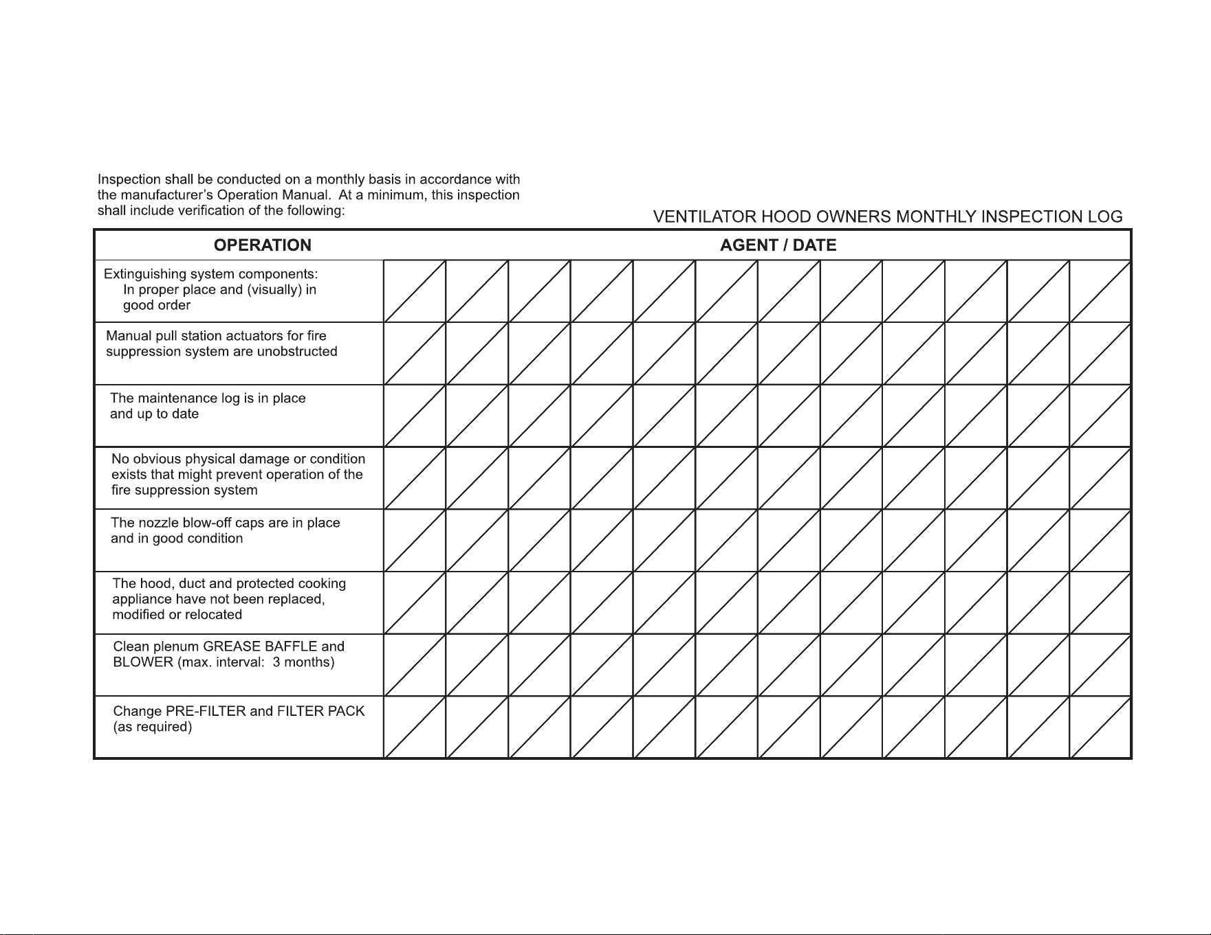
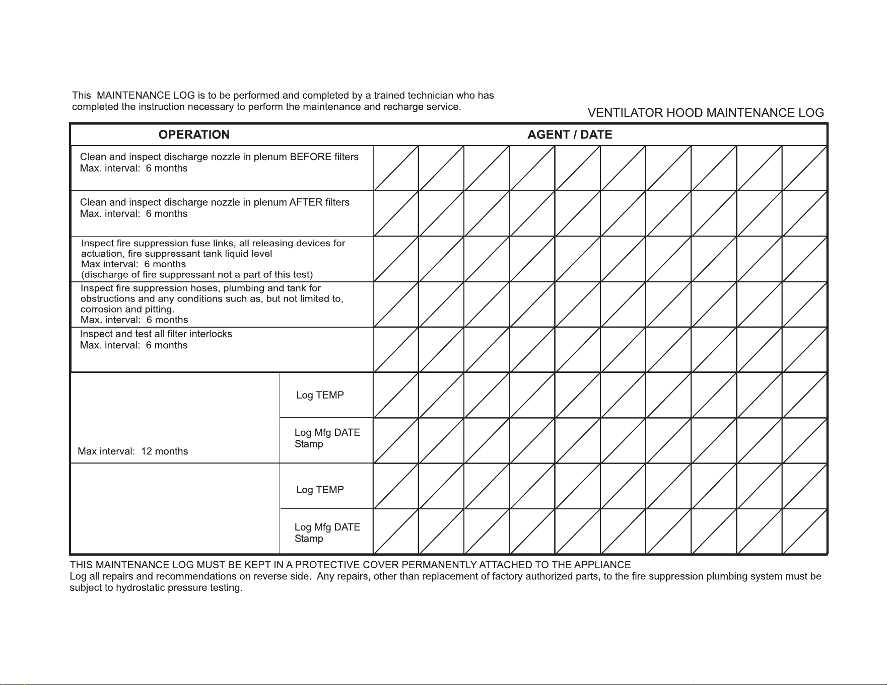
MAINTENANCE SCHEDULES
1. 6-MONTH MAINTENANCE (MUST BE PERFORMED BY AN
AUTHORIZED ANSUL® DISTRIBUTOR ONLY):
a. Inspect and test total operation including FIRE DAMPER and
all SAFETY INTERLOCKS.
b. All FIRE SUPPRESSION SYSTEM actuation components
including MANUAL PULL STATION and any REMOTE
MANUAL PULL STATION must be inspected for proper
operation in accordance with the maintenance schedule
published in ANSUL® R-102 SYSTEM DESIGN,
INSTALLATION, RECHARGE AND MAINTENANCE MANUAL
(Ansul® #418087-05).
c. The FIRE SUPPRESSION SYSTEM FUSIBLE LINKS must be
inspected. NOZZLES and MANUAL PULL STATION must be
cleaned in accordance with ANSUL® R-102 SYSTEM
DESIGN, INSTALLATION, RECHARGE AND MAINTENANCE
MANUAL (Ansul® #418087-05).
d. The FIRE SUPPRESSION AGENT TANK, PIPING and
FLEXIBLE TUBING must be INSPECTED.
2. 12-YEAR MAINTENANCE: (MUST BE PERFORMED BY AN
AUTHORIZED ANSUL® DISTRIBUTOR ONLY):
a. The FIRE SUPPRESSION AGENT TANK and ¼” FLEX HOSE
must be HYDROSTATICALLY TESTED, and the FIRE
EXTINGUISHING AGENT must be REPLACED in accordance
with the maintenance schedule published in ANSUL® R-102
SYSTEM (STANDARD UL 300 LISTED).
b. The FUSIBLE LINKS in plenum and damper must be
REPLACED. This maintenance to be performed by qualified
Ansul® service personnel only.
USE AND MAINTENANCE
SHALL BE IN ACCORDANCE
WITH THE STANDARD FOR
VENTILATION CONTROL
AND FIRE PROTECTION OF
COMMERCIAL COOKING
OPERATIONS, N.F.P.A 17A
& N.F.P.A. 96 (current
editions).
DANGER
FIRE
HAZARD
FAILURE TO PROPERLY
CLEAN AND MAINTAIN THIS
EQUIPMENT CAN
CAUSE A FIRE. AN
UNCONTROLLED FIRE CAN
CAUSE SERIOUS INJURY,
DEATH AND/OR PROPERTY
LOSS.
NOTE: A signed and dated
VENTILATOR HOOD
MAINTENANCE LOG must
be maintained on the
premises, and shall be
available for inspection by the
authority having jurisdiction.
See pages 26 & 27.
IMPORTANT: Parts used
for the Ansul® fire
suppression system are not
serviceable by the owner /
operator. Procedures for
servicing fire suppression
equipment are described in:
ANSUL® R-102 SYSTEM
DESIGN, INSTALLATION,
RECHARGE AND
MAINTENANCE MANUAL
(Ansul® #418087-05).
30
M507 p/n 2M-304446 Owners Manual WV-FG
31
WELLS BLOOMFIELD, LLC
M507 p/n 2M-304446 Owners Manual WV-FG
32
Replace two (2) fire suppression
links at cooking appliance:
each link is rated @ 212ºF
WELLS BLOOMFIELD, LLC
Replace fire damper fusible link:
rated @ 280ºF
Max interval: 12 months
M507 p/n 2M-304446 Owners Manual WV-FG
ANSU
L
®
ANSUL INCORPORATED
MARINETTE, WI 54143-2542
MATERIAL SAFETY DATA SHEET
ANSULEX Low pH
QUICK IDENTIFIER (In Plant Common Name)
Manufacturer’s
Name:
Emergency
Telephone No.:
ANSUL INCORPORATED
CHEMTREC
(800) 424-9300 or (703) 527-3887
Prepared By:
Address:
One Stanton Street, Marinette, WI 54143-2542
Safety and Health Department
Other Information
Calls:
(715) 735-7411
Date Prepared:
February 1, 1999
SECTION 1 - IDENTITY
SECTION 2 - INGREDIENTS
SECTION 3 - PHYSICAL AND CHEMICAL CHARACTERISTICS (Fire and Explosion Data)
SECTION 4 - PHYSICAL HAZARDS
Common Name (Used on Label):
(Trade Name and Synonyms)
ANSULEX Low pH Liquid Fire Suppressant
CAS No.:
N/A
N/A N/A N/A N/A
N/A
N/A
N/A
N/A
N/A N/A
N/E
N/E
N/E
N/E
N/E
NDA
NDA
NDA
NDA
N/A
Chemical
Name:
N/A This is a Mixture
Chemical
Family:
Mixture
Formula:
PART A - HAZARDOUS INGREDIENTS
PART B - OTHER INGREDIENTS
Principal Hazardous Component(s) (chemical and common name(s)):
Other Component(s) (chemical and common name(s)):
Wt.%
Wt.%
CAS No.
CAS No.
ACGIH TLV
ACGIH TLV
Acute Toxicity Data
Acute Toxicity Data
None
Proprietary Mixture of Organic and Inorganic Salts
48.0 - 50.0
Phosphoric Acid 0.2
7664-38-2
Yellow-Green Fluorescent Dye 0.011
518-47-8
Oral LD (rat)
50
6800 mg/kg
EDTA
0.65
64--02-8
Water
Approx. 50.0
7732-18-5
Boiling
Point:
Percent Volatile
by Volume (%):
Solubility
in Water:
Appearance
and Odor:
Flash Point:
Special Fire
Fighting Procedures:
Unusual Fire and
Explosion Hazards:
113ºC
Approx. 50.0
100%
Fluorescent Yellow Colored Liquid, Mild Odor
None to boiling
NONE - THIS IS AN EXTINGUISHING AGENT
None
Vapor Density:
(Air = 1):
Flammable Limits
in Air % by Volume:
1.03
Specific
Gravity (H O=1):
2
Vapor Pressure
(mm Hg):
1.33
Not Determined
Evaporation Rate:
(Butyl Acetate=1):
Approx. 0.005
Reactivity in
Water:
Mild exothermic reaction
Extinguisher
Media:
Auto-Ignition
Temperature:
Stability:
Incompatibility
(Materials to Avoid):
Hazardous
Decomposition Products:
Hazardous
Polymerization:
Unstable
Stable
Conditions
to Avoid:
Conditions
to Avoid:
Reactive Metals, ClF , electrically energized equipment, any material reactive with water.
3
Not established, acrid fumes.
May Occur
Will Not Occur
33
SECTION 5 - HEALTH HAZARD
S
SECTION 6 - EMERGENCY AND FIRST AID PROCEDURES
SECTION 7 - SPECIAL PROTECTION INFORMATION
SECTION 8 - SPECIAL PRECAUTIONS AND SPILL/LEAK PROCEDURES
HAZARDOUS MATERIAL IDENTIFICATION SYSTEM
ANSULEX Low pH (continued)
Threshold
Limit Value:
None Established
Routes of Entry:
Eye Contact:
Irritant
Irritant
Skin Contact:
Skin Contact:
Inhalation:
Inhalation:
Not an expected route of entry. Can be irritating to mucous membranes.
Irritating to mucous membranes. Acute Oral LD (Sprague-Dawley rats) 825.5mg/kg.
50
Ingestion:
Ingestion:
Signs and
Symptoms:
Acute Exposure: Material irritates skin, eyes, and mucous membranes.
Chronic Exposure: None known.
Medical Conditions Generally
Aggravated by Exposure:
None known.
Chemical Listed as
Carcinogen or Potential:
Yes
No
Yes
No
Yes
No
National Toxicology
Program:
I.A.R.C
Monographs:
OSHA
Eye Contact:
Flush and irrigate with water for 15 minutes while holding eyelids open.
If irritation persists, seek medical attention.
Wash thoroughly with soap and water. If irritation persists, seek medical attention.
Fresh air if symptoms occur. If irritation persists, seek medical attention.
Dilute by drinking large quantities of water.
Respiratory Protection
(Specify Type):
N/A
N/A N/A
Ventilation:
Local
Exhaust:
Mechanical
(General):
Protective
Gloves:
Rubber gloves for spill/leak
Eye
Protection:
Chemical goggles recommended during
spill/leak procedures.
Other Protective
Clothing or Equipment:
Eye wash and safety showers are good safety practice.
Precautions to be taken
in Handling and Storage:
Other
Precautions:
Steps to be taken in Case
Material is Released or Spilled:
Waste Disposal
Methods:
Store in original container. Keep tightly closed. Keep separate from acid.
See incompatibility information in Section 4.
Stop leaks. Contain spills. Remove as much as possible. Place in closed container for proper disposal
Wash spill area with large amounts of water to remove traces and neutralize.
Dispose of in compliance with local, state and federal regulations.
HAZARD INDEX
4 SEVERE HAZARD 0 HEALTH
3 SERIOUS HAZARD
2 MODERATE HAZARD 0 FLAMMABILITY
1 SLIGHT HAZARD
0 MINIMAL HAZARD 0 REACTIVITY
N/A = Not Applicable NDA = No Data Available N/E = Not Established
ANSUL and ANSULEX are registered trademarks.
Internet Address: http://www.ansul.com
ANSUL INCORPORATED, ONE STANTON STREET, MARINETTE, WI 54143-2542 Form No. F-90160-6 ©1999 Ansul Incorporated
34
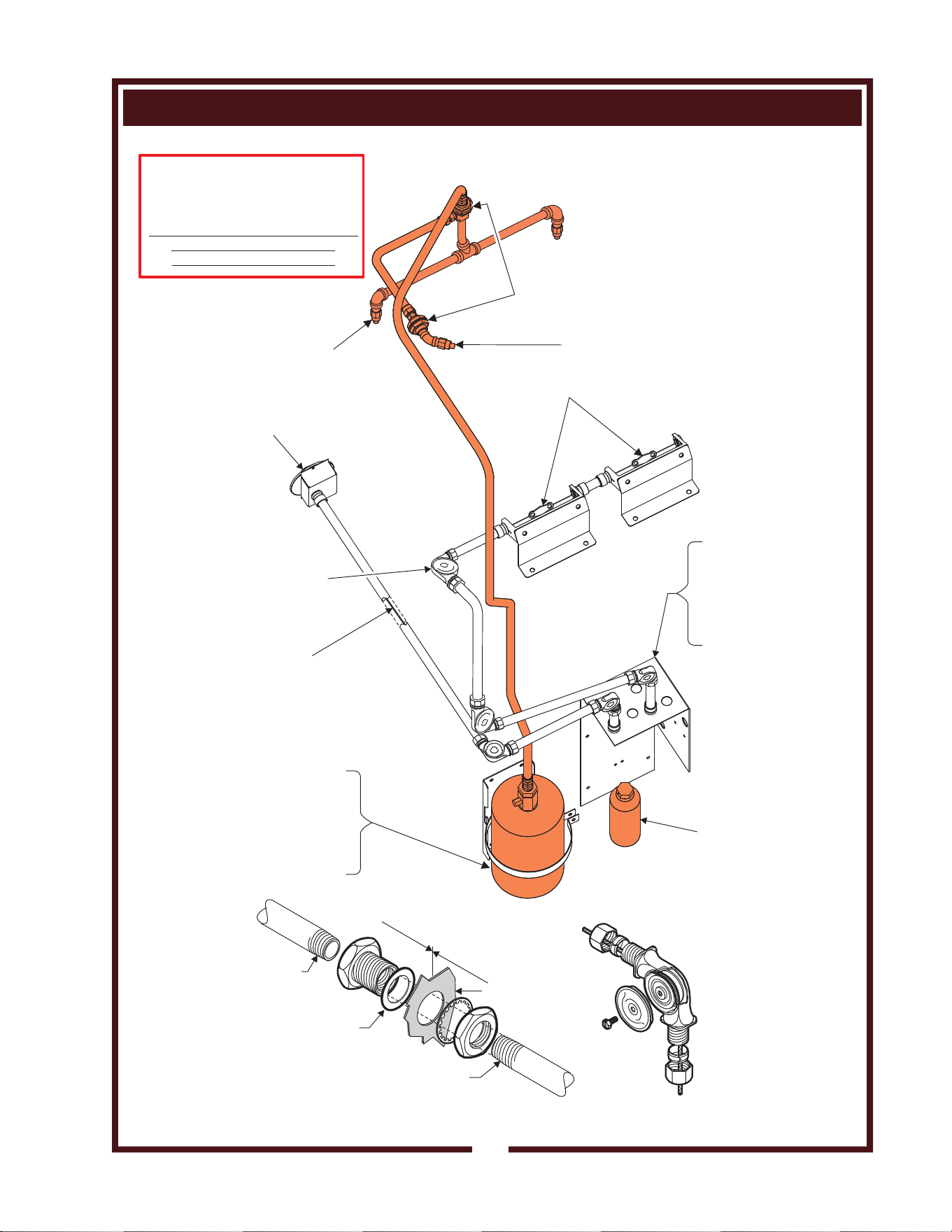
ANSUL® FIRE SUPPRESSION SYSTEM COMPONENTS
35
M507 p/n 2M-304446 Owners Manual WV-FG
ANSUL© p/n 77284
DETAIL
inside
outside
cabinet wall
Seal with
Teflon tape
Seal with
Teflon tape
Fiber
washer
is always
on the inside
ANSUL© p/n 423250
DETAIL
Cable sits in
groove in
pulley
ref. NOZZLE 1W
ANSUL© p/n 419336
ref. NOZZLE 290
ANSUL© p/n 419342
(2 places)
ref. ADAPTER, QUICK-SEAL 3/8”
ANSUL© p/n 77284
ref. MOUNTING BRACKET
RELEASE MECHANISM
R-102 ANSUL© p/n 79493
(NOT SHOWN)
ANSULEX ® EXTINGUISHING
AGENT 1.5 GAL.
ANSUL© p/n 79694
(NOT SHOWN)
MICROSWITCH 67273
TERM.BLOCK 53068
FRONT OF UNIT
BACK OF UNIT
FOR USE ONLY BY AUTHORIZED
ANSUL© SERVICE PERSONNEL
Refer to Ansul© part no. 418078-05
R-102 Restaurant Fire Suppression
System Design, Installation,
Recharge and Maintenance
ref. TANK 1.5 GAL, ANSULEX®
ANSUL© p/n 429864
FUSIBLE LINK 212ºF
MODEL K 503037
ASSY, PULL STATION
ANSUL© 501389
ref. PULLEY ELBOW
ANSUL© p/n 423250
(typical)
ref. CABLE, WIRE ROPE
ANSUL© p/n 15821 (50’/15m)
79653 (500’/152m) (typical)
CARTRIDGE LT-20-R
ANSUL© p/n 67099
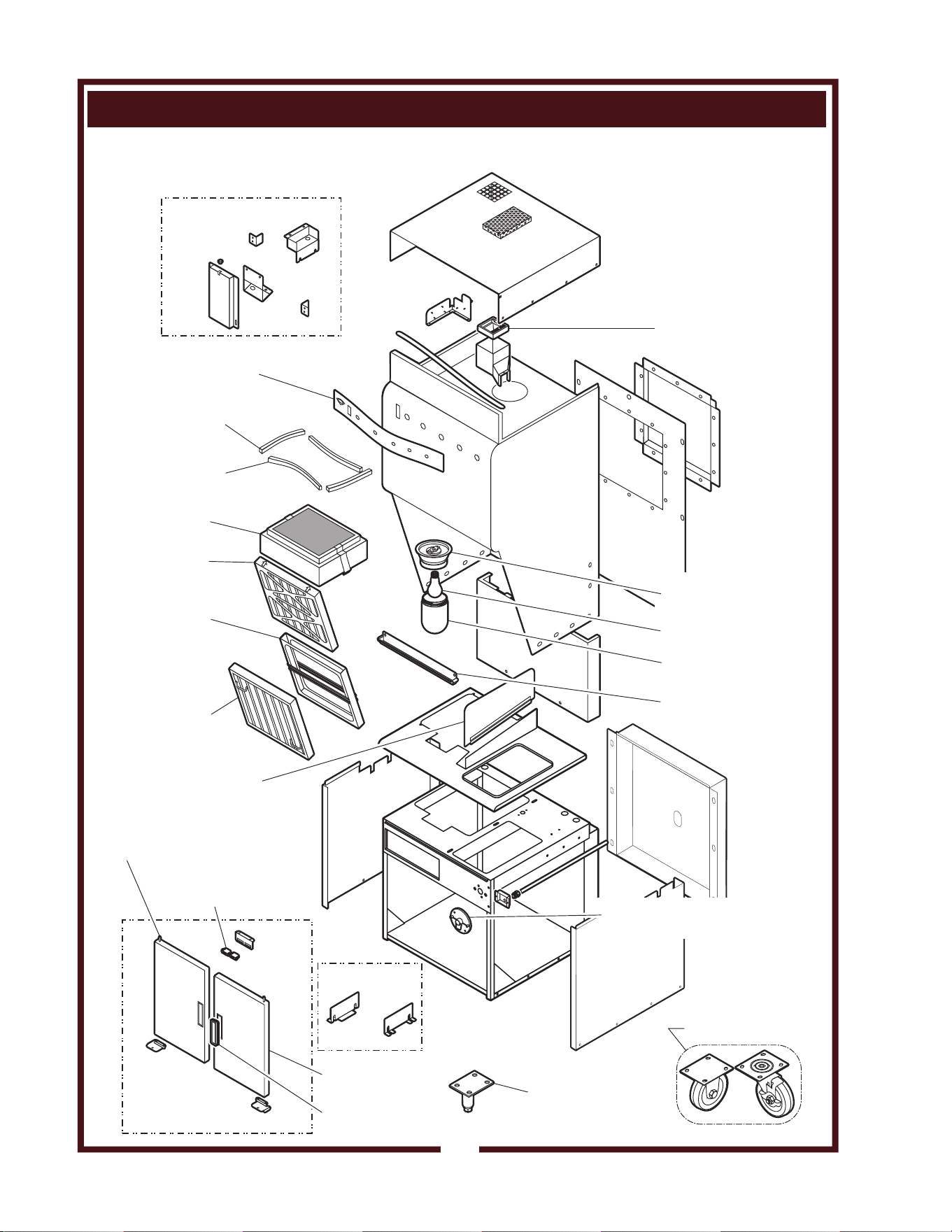
EXPLODED VIEW & PARTS LIST
36
M507 p/n 2M-304446 Owners Manual WV-FG
HOOD SECTION - CABINET COMPONENTS
INTERNAL BRACKETS
LEG, ADJUSTABLE
VCS 5M-22649 (pk 2)
(REAR LEG OPTION)
SET, CASTERS
5E-20804
(2 swivel, 2 fixed)
ASSY, PULL STATION
ANSUL 2O-301389
CABINET DOORS
(NON -RW UNITS)
-RW UNITS
ASSY, DOOR
RIGHT M3-302646
ASSY, DOOR
LEFT M3-302642
MAGNET, DOOR
CATCH 2R-46502 (2 pl)
HANDLE, DOOR
SNAP-IN 2R-302166
LABEL, CONTROL
PANEL DD-502782
GASKET, SILICONE
15-1/4” WS-502772 (2 pl)
GASKET, SILICONE
18-1/2” WS-502773 (2 pl)
ASSY, FILTER
PACK 5N-22619
PREFILTER
5N-22618
CAGE,
PRE-FILTER
5M-22683
BAFFLE, GREASE
FILTER (TYPE 3)
5M-22684
HOUSING, LIGHT
SOCKET 2E-305098
BULB, APPLIANCE
100W 2S-305100
GLASS GLOBE, LIGHT
BULB COVER 2Q-305099
GREASE CUP
M3-304405
FIRE DAMPER ASSY
280ºF (ref. 2V-301187)
EXTENSION, GRIDDLE
SPLASHGUARD M3-304415
IL1953-PL507
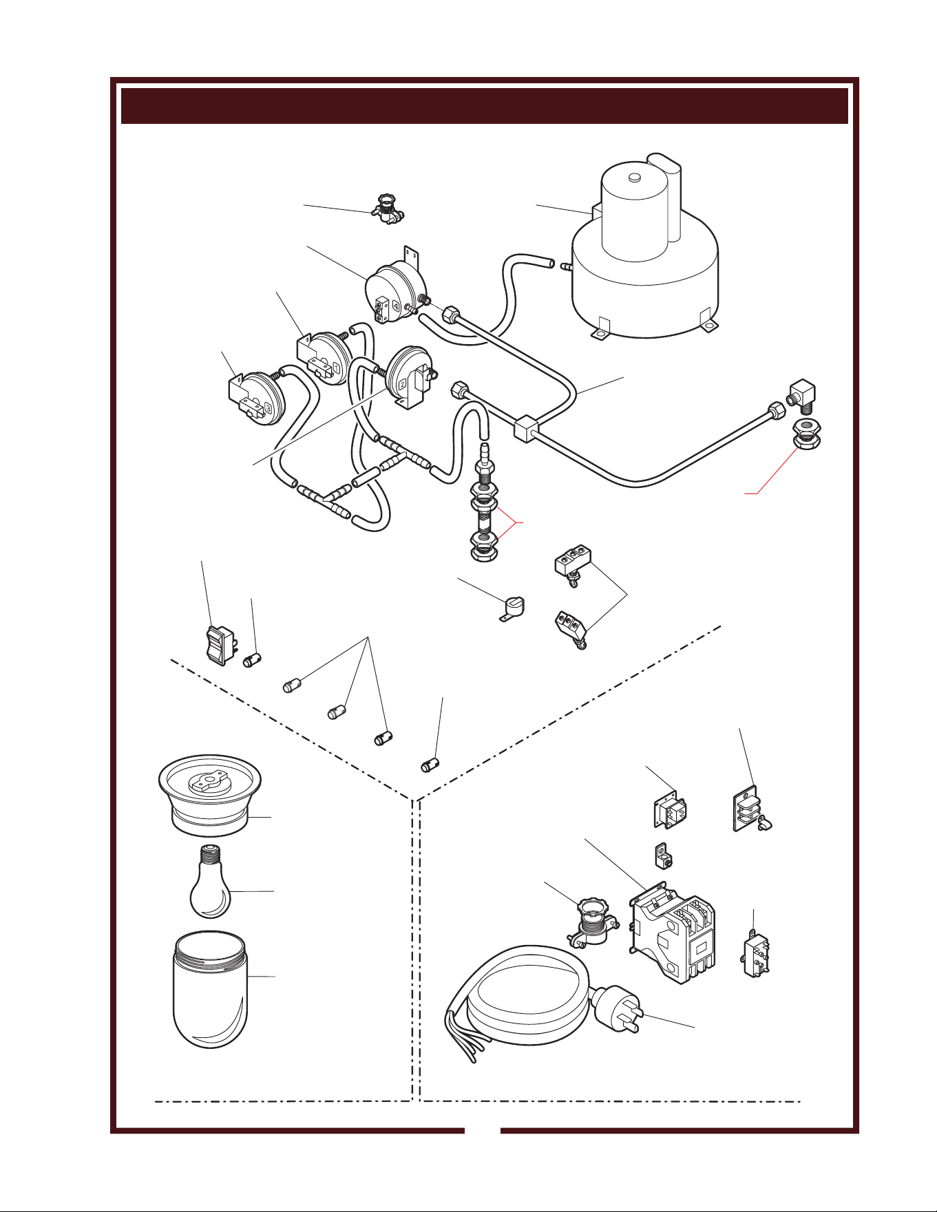
EXPLODED VIEW & PARTS LIST
37
M507 p/n 2M-304446 Owners Manual WV-FG
HOOD SECTION - ELECTRICAL & VACUUM COMPONENTS
FRONT OF HOOD
ELECTRICAL - UPPER HOOD
ELECTRICAL - UNDER HOOD
ELECTRICAL - REAR OF LOWER CABINET
ref Ansul®
77284
ref Ansul®
77284
FITTING, 1/2” CONDUIT
STRAIGHT 2K-37748X
ASSY, BLOWER
240V 2U-302584
VACUUM SWITCH
#4 2E-302593
VACUUM SWITCH
#1 2E-302590
VACUUM SWITCH
#3 2E-302592
VACUUM SWITCH
#2 2E-302591
ASSY, VAC TUBE
MANIFOLD WS-502588
SWITCH, POWER
2E-70395
LIGHT, INDICATOR
GREEN 240V 2J-35697
LIGHT, INDICATOR
AMBER 240V 2J-30516 (3 pl)
LIGHT, INDICATOR
RED 240V 2J-31157
BUZZER, 240V
2J-44834
SWITCH, FILTER
INTERLOCK
2E-300407 (2 pl)
HOUSING, LIGHT
SOCKET 2E-305098
BULB, APPLIANCE
230V 100W 2S-305100
GLASS GLOBE
LIGHT BULB
COVER 2Q-305099
TERMINAL BLOCK
2P 250V 2E-33068
JUMPER, FLAME
SENSOR 2E-34005
RELAY, 208/240V
(-RW, -RWT ONLY) 2E-43880
CONTACTOR 208/240V
50A 3-PH 2E-302789
75A 1-PH 2E-306040
STRAIN RELIEF
1-1/4” 2K-304420
RELAY, BLDG
FIRE ALARM
2E-44514
POWER CORD
NEMA 15-60P
M3-303130
(incl. strain relief)
IL1954a-PL50
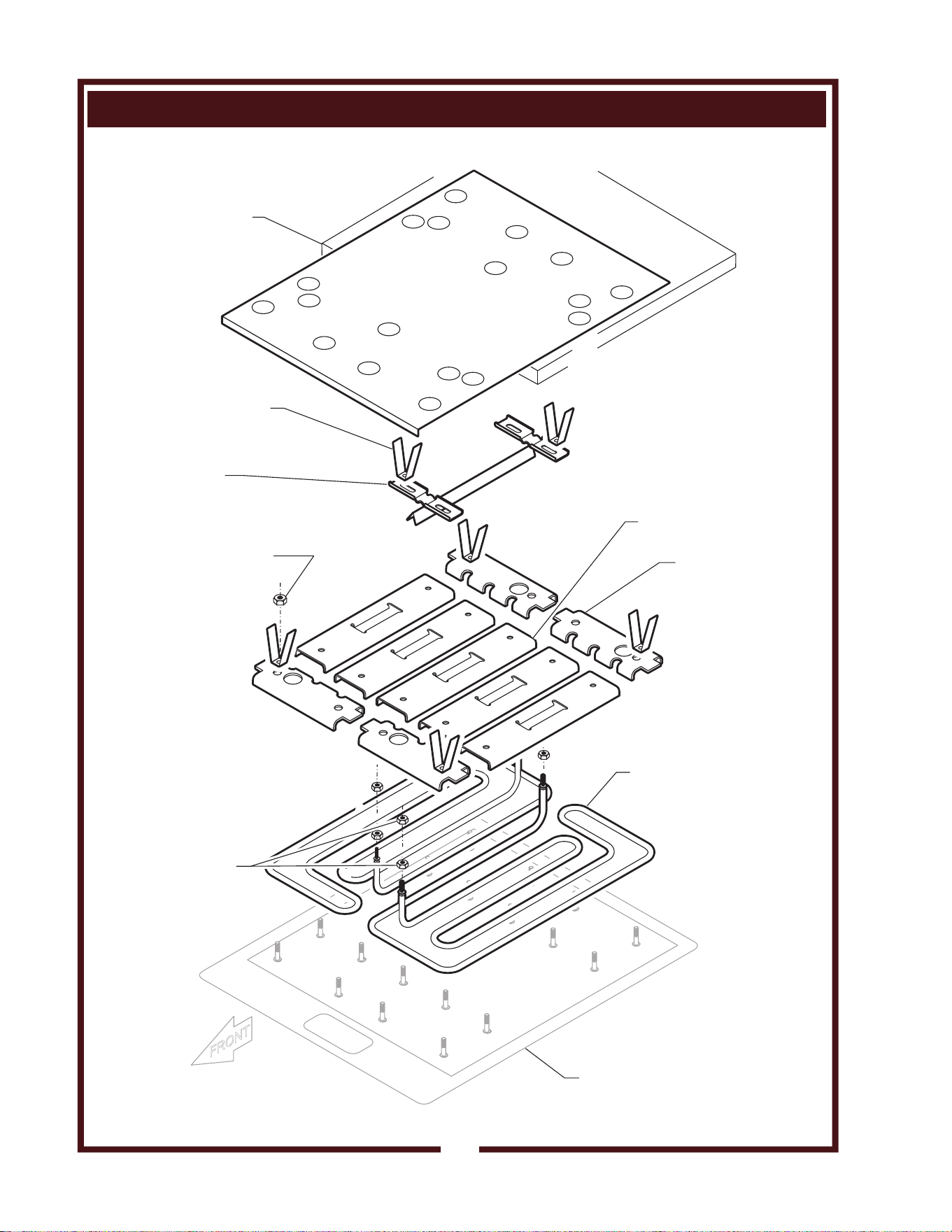
EXPLODED VIEW & PARTS LIST
38
M507 p/n 2M-304446 Owners Manual WV-FG
GRIDDLE SECTION - GRIDDLE PLATE & HEATING ELEMENT COMPONENTS
HEATING ELEMENT
2N-30512UL (240V) (2ea)
NUT, 10-32 HEX
2C-35313 (16 ea)
NUT, 1/4-20 HEX Ni
2C-31253 (36 ea)
CLAMP, ELEM END
G7-32038 (4 ea)
CLAMP, ELEM CENTER
G7-31968 (5 ea)
CLAMP, THERMO
G7-32028 (4 ea)
CLIP, INSULATION
G7-33474 (6 ea)
GRIDDLE
SHOWN INVERTED
(ref.)
INSULATION PAD
2H-36051 (pk 2'x4')
IL1955-PL507
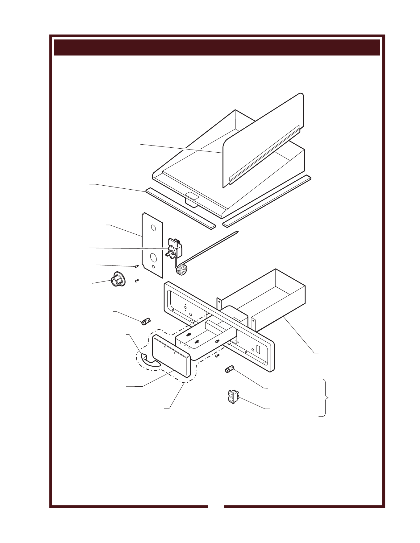
EXPLODED VIEW & PARTS LIST
39
M507 p/n 2M-304446 Owners Manual WV-FG
GRIDDLE SECTION - CABINET & ELECTRICAL COMPONENTS
LIGHT, SIGNAL AMBER
2J-30516
SHROUD, GREASE
DRAWER WS-51989
HANDLE
2R-38668
TRAY FRONT
G7-Z12047
GREASE TRAY ASSY
COMPLETE WS-50279
SEALANT 1/4”x98”
1P-33306
SHIELD, THERMO
2A-31974 (2 reqd)
KNOB
2R-302826
THERMO, CONTROL
2T-302825
SCREW, 6-32x3/16
2C-31718
LIGHT, SIGNAL RED
2J-31157
SWITCH 2P 50A
2E-74098
PART OF
FRYER
SECTION
EXTENSION, GRIDDLE
SPLASHGUARD M3-304415
IL1956-PL507
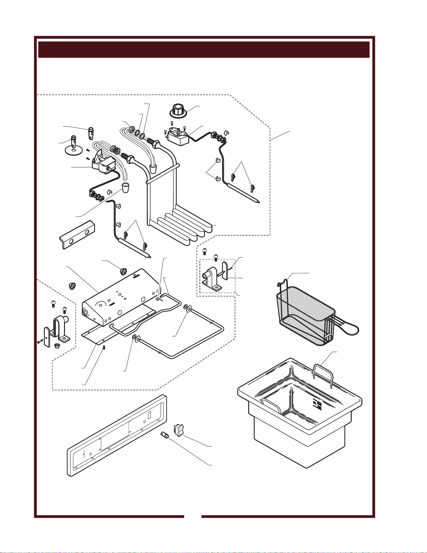
M507 p/n 2M-304446 Owners Manual WV-FG
EXPLODED VIEW & PARTS LIST
40
RESET
WS-52427
2D-301344
2C-31207
2C-31208
2P-34452
E7-30464
WS-58656
2J-31157
2J-31157
2J-30516
2R-35511
2C-49689
2C-49689
2C-30157
WS-55510
2N-42842UL(208V)
2N-42866UL(240V)
WS-50183
2A-32806
red
red
amber
2C-30176
2I-Z12311
2C-30172
fiber washer
2C-31717
E7-35028
basket,
1/2 size
2B-43688
2C-35566
lock washer
temp control
thermo,
hi-limit safety
HEAD ASSY
COMPLETE
208V WS-504417
240V M3-306061
2E-307316
nut 7/8-14
heating element
clip, capillary
clip,
thermobulb
clip,
thermobulb
cap, push-on
rod,
support
frypot
washer,
neoprene
washer,
flat SS
control
box
cover
assy, pivot
cover,
pivot
connector 12-14 ga
2P-32428
spring
switch, 2P 50A
2E-74098
IL2318, Rev. A
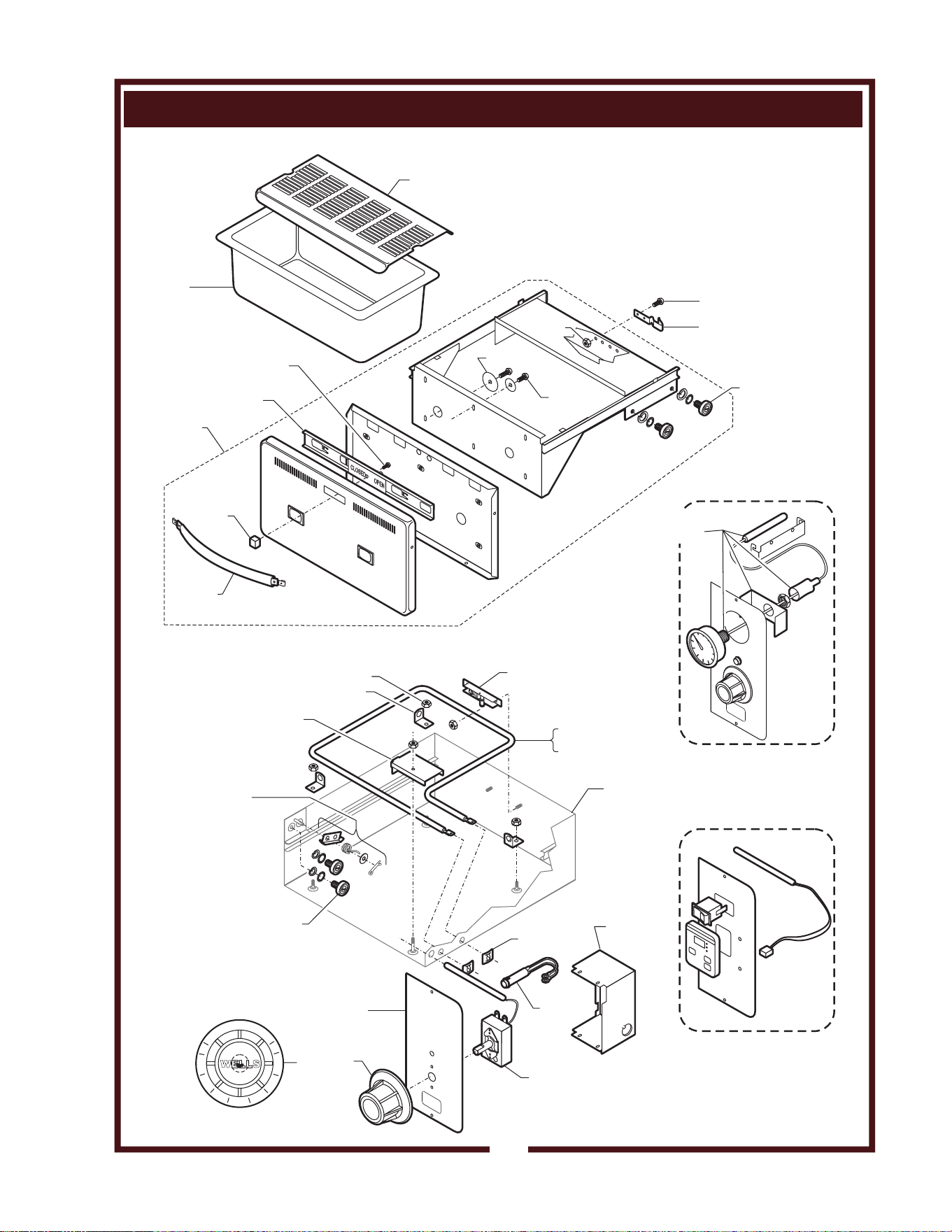
EXPLODED VIEW & PARTS LIST
M507 p/n 2M-304446 Owners Manual WV-FG
DRAWER WARMER SECTION - CABINET & ELECTRICAL COMPONENTS
CLOSED OPEN
2C-35487
part of 2C-30471
2P-30483
2C-35455
2C-35487
2C-35565
5C-20624
(optional)
2C-35530
5C-21488
C8-49251
WS-51796
C8-32112
WS-67096
heavy-duty
drawer assy
complete
2C-30471 (includes
strike and catch)
C8-35677
C8-35683
2N-30482UL (240V)
2N-30519UL (120V)
2P-30483
2C-35455 (typ.)
2T-44475
OPTIONAL
THERMOMETER
OFF
0
L
O
H
I
WELLS
2
3
4
5
6
7
8
2R-30372
C8-31801(UPPER)
C8-33565 (LOWER)
WS-65923
(set - includes left
and right)
C8-307637 (CAVITY ASSEMBLY)
2C-43271
WS-58936
2J-35687
C8-307569
-RWT ELECTRONIC CONTROL
OPTION (PART NO. PENDING)
IL1957-PL507
41
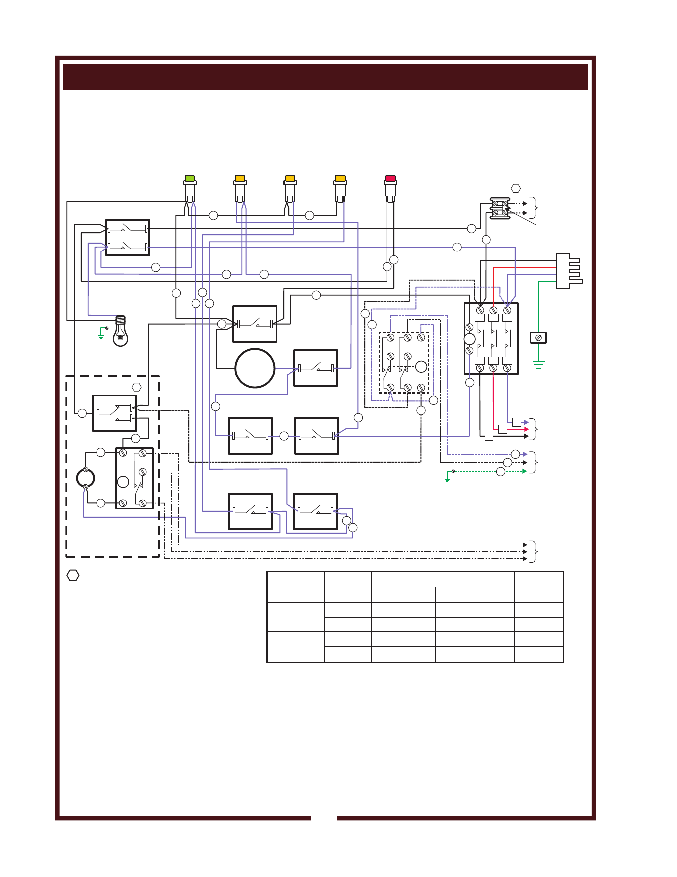
WIRING DIAGRAM
42
HOOD SECTION
VACUUM SWITCH
VS4 (AIRFLOW)
VACUUM SWITCH
VS1 (PREFILTER)
VACUUM SWITCH
VS3 (PREFILTER)
VACUUM SWITCH
VS2 (FILTER PACK)
C
C
C
CONTACTOR
208/240VAC
75 AMPS
GROUND
EXTERNAL
CONTROL
TERMINAL
BLOCK
L1
T1
L2
T2
L3
T3
VENTILATOR
POWER SWITCH
3
1
2
POWER
CORD
COOKING
APPLIANCE
BUILDING
ALARM
SYSTEM
EXTERNAL
SHUTDOWN
CONTROL
DRAWER
WARMER
NC
NO
C
FIRE SWITCH
23
24
15
16 13
6
7
10
NO
NO
NONO
NO
NO
POWER ON
INDICATOR
CHECK
FILTER
INDICATOR
REPLACE
PREFILTER
INDICATOR
REPLACE
FILTER PACK
INDICATOR
SERVICE
REQUIRED
INDICATOR
HOOD
LIGHT
BLACK
BLACK
RED
WHITE
GREASE BAFFLE
POSITION SW
FILTER PACK
POSITION SW
1
2
19
18
17
5
9
DRAWER
WARMER
RELAY
1
1
2
2
3
3
4
4
5
5
6
DISCHARGE
BUZZER
BUILDING
ALARM
RELAY
ANSUL SYSTEM®
1. REMOVE JUMPER WHEN USING
EXTERNAL CONTROL.
DO NOT CONNECT ANY POWER TO
EXTERNAL CONTROL TERMINAL BLOCK!
IMPORTANT:
2. FIRE SWITCH SHOWN WITH
ANSUL® SYSTEM CHARGED
AND COCKED
NOTES
JUMPER
BLOWER
MOTOR
14
12
4
21
22
25
34
37
31
32
33
35
36
1
2
3
27
11
8
26
from part no. 304419 issue B
MODEL
VOLTS
60Hz
3ø AMPS
1ø
AMPS
WATTS
L1 L2 L3
208V
240V
208V
240V
WV-FG
10,800
30 43 24
52
11,700
26 40 24 49
WV-FGRW
WV-FGRWT
11,500
32 43 26 55
12,600
28 40 27
53
M507 p/n 2M-304446 Owners Manual WV-FG
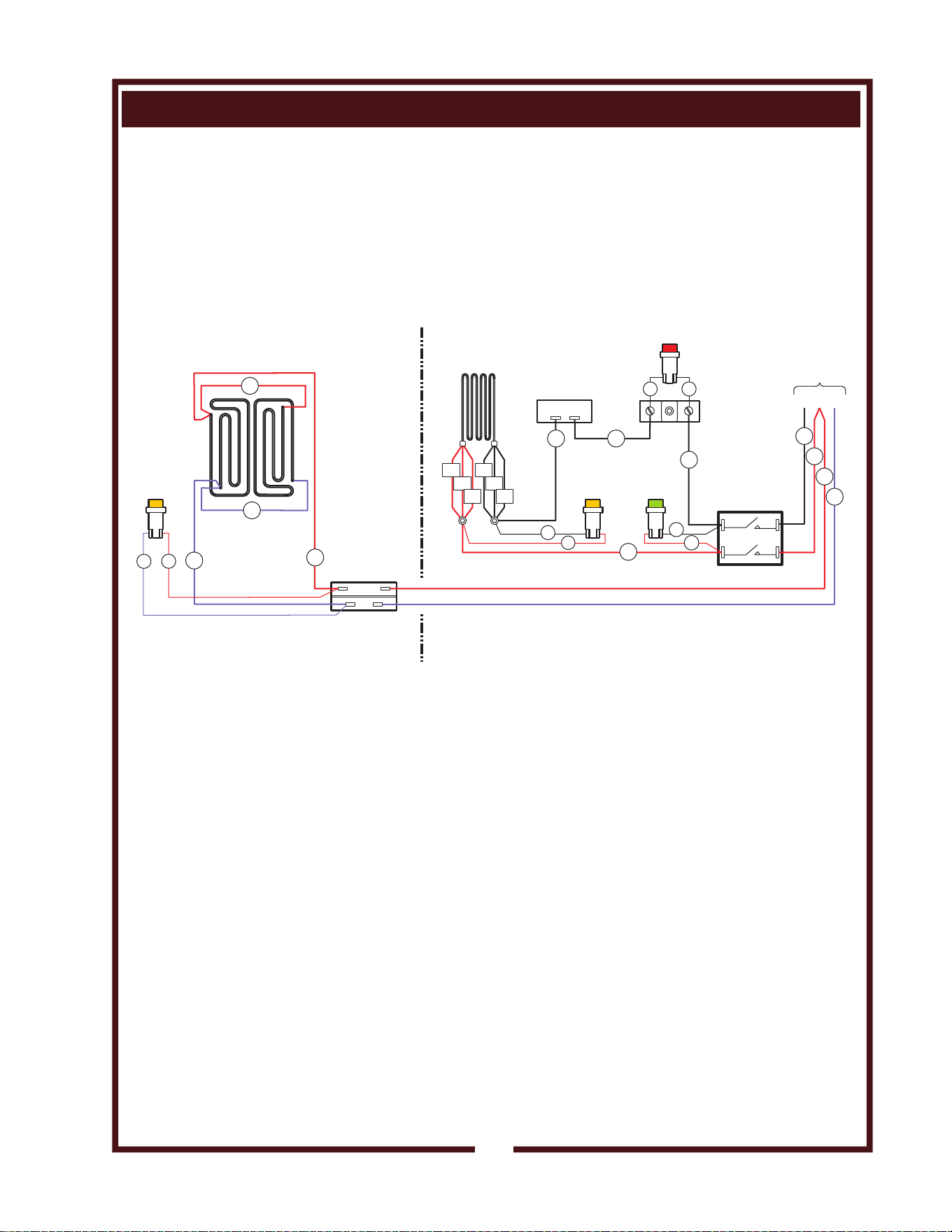
WIRING DIAGRAM
42
M507 p/n 2M-304446 Owners Manual WV-FG
COOKTOP SECTION
TROUBLE
LIGHT (RED)
FRYER
CONTROL
THERMOSTAT
GRIDDLE
CONTROL
THERMOSTAT
HI-LIMIT
T'STAT
WIRING DIAGRAM WV-FG
from part no. 304419
TEMP
LIGHT
(AMBER)
L1
L2
L3
FROM
COOKING
APPLIANCE
CONTACTOR
FRYER
HEATING
ELEMENT
GRIDDLE
HEATING
ELEMENTS
FRYER
POWER SWITCH
TEMP
LIGHT
(AMBER)
POWER
LIGHT
(GREEN)
56
59
58
67
6968
63
62
64
65
70
60
61
71
7273
66
52
55
51
L1 L1
L2 L2
L3 L3
FRYER SECTIONGRIDDLE SECTION
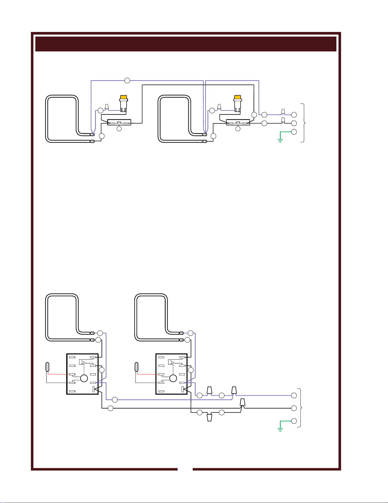
WIRING DIAGRAM
43
DRAWER WARMER SECTION (RW-STYLE)
DRAWER WARMER SECTION (RWT-STYLE)
UPPER
HEATING
ELEMENT
240VAC
900WATTS
T T
FROM
DRAWER
WARMER
RELAY
INDICATOR
LIGHT
INDICATOR
LIGHT
WIRE
NUT
WIRE
NUT
WIRE
NUT
WIRE
NUT
THERMOSTAT
THERMOSTAT
LOWER
HEATING
ELEMENT
240VAC
900WATTS
3232
77
88
1
314
33
WIRING DIAGRAM RW-26
from p/n 300959 issue A
UPPER
HEATING
ELEMENT
240VAC
900WATTS
UPPER
HEATING
ELEMENT
240VAC
900WATTS
FROM
DRAWER
WARMER
RELAY
32
31
33
WIRING DIAGRAM RWT-26
from p/n 307532 issue (-)
1 1
2 2
3 3
4 4
5 5
6 6
7 7
8 8
9 9
10 10
E E
CONTROLLER CONTROLLER
TEMP
PROBE
TEMP
PROBE
CONNECTOR CONNECTOR
CONNECTOR
CONNECTOR
9
8
6
3
3
55
77
6
44
CUSTOMER SERVICE DATA
please have this information available if calling for service
RESTAURANT _____________________________ LOCATION _____________
INSTALLATION DATE ________________________ TECHNICIAN ___________
SERVICE COMPANY ________________________________________________
ADDRESS ___________________________ STATE ______ ZIP__________
TELEPHONE NUMBER (_____)_____-_________
EQUIPMENT MODEL NO. _______________
EQUIPMENT SERIAL NO. _______________
VOLTAGE: (check one) 208 240
DESCRIPTION SERVICE
PART NO.
OVEN RACK Replacement 5F-21376
PRE-FILTER 5N-22618
PRE-FILTER CAGE 5M-22683
FILTER PACK (HI-EFFICENCY + CHARCOAL) 5N-22619
GREASE BAFFLE 5M-22684
GREASE DRIP TRAY M3-304405
LEG KIT 5F-22829
CASTER KIT DD-22830
FRY BASKET, HALF-SIZE 5E-20161
FRY BASKET, FULL SIZE 5E-20162
CRUMB CRADLE, FRYER 5E-20690
FRYPOT, 5E-20169
COVER, FRYPOT 5E-21010
HUMITROL RACK 5C-20624
DRAWER WARMER PAN DD-22412
WELLS BULLETIN (ANSUL® PARTS LIST) DD-303331
NOTE: Ansul® Manual 418087-05 and
Wells Bulletin 303331 are intended for use
by authorized Ansul® service personnel only.
Ansul® Manual 418087-05 must be obtained
through your authorized Ansul® distributor.
PARTS & SERVICE
45
IMPORTANT: Use only
factory authorized service
parts and replacement
filters.
For factory authorized
service, or to order factory
authorized replacement parts,
contact your Wells authorized
service agency, or call:
Wells Bloomfield, LLC
10 Sunnen Dr.,
St. Louis MO 63143 USA
Service Dept.
phone: (314) 678-6314
fax: (314) 781-2714
Service Parts Department can
supply you with the name and
telephone number of the
WELLS AUTHORIZED
SERVICE AGENCY
nearest you.
WELLS BLOOMFIELD, LLC
10 Sunnen Dr., St. Louis, MO 63143
telephone: 314-678-6314
fax: 314-781-2714
www.wells-mfg.com