WELLS MANUFACTURING
265 Hobson Street, Smithville, Tennessee 37166
telephone: 314-678-6314
fax: 314-781-2714
www.wells-mfg.com
IMPORTANT: DO NOT DISCARD THIS MANUAL
This manual is considered to be part of the appliance and is to be given to the OWNER or
MANAGER of the restaurant, or to the person responsible for TRAINING OPERATORS of
this appliance. Additional manuals are available from your WELLS DEALER.
THIS MANUAL MUST BE READ AND UNDERSTOOD BY ALL PERSONS USING OR
INSTALLING THIS APPLIANCE. Contact your WELLS DEALER if you have any
questions concerning installation, operation or maintenance of this equipment.
OWNER
'S MANUAL
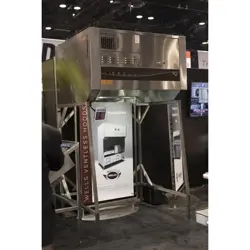
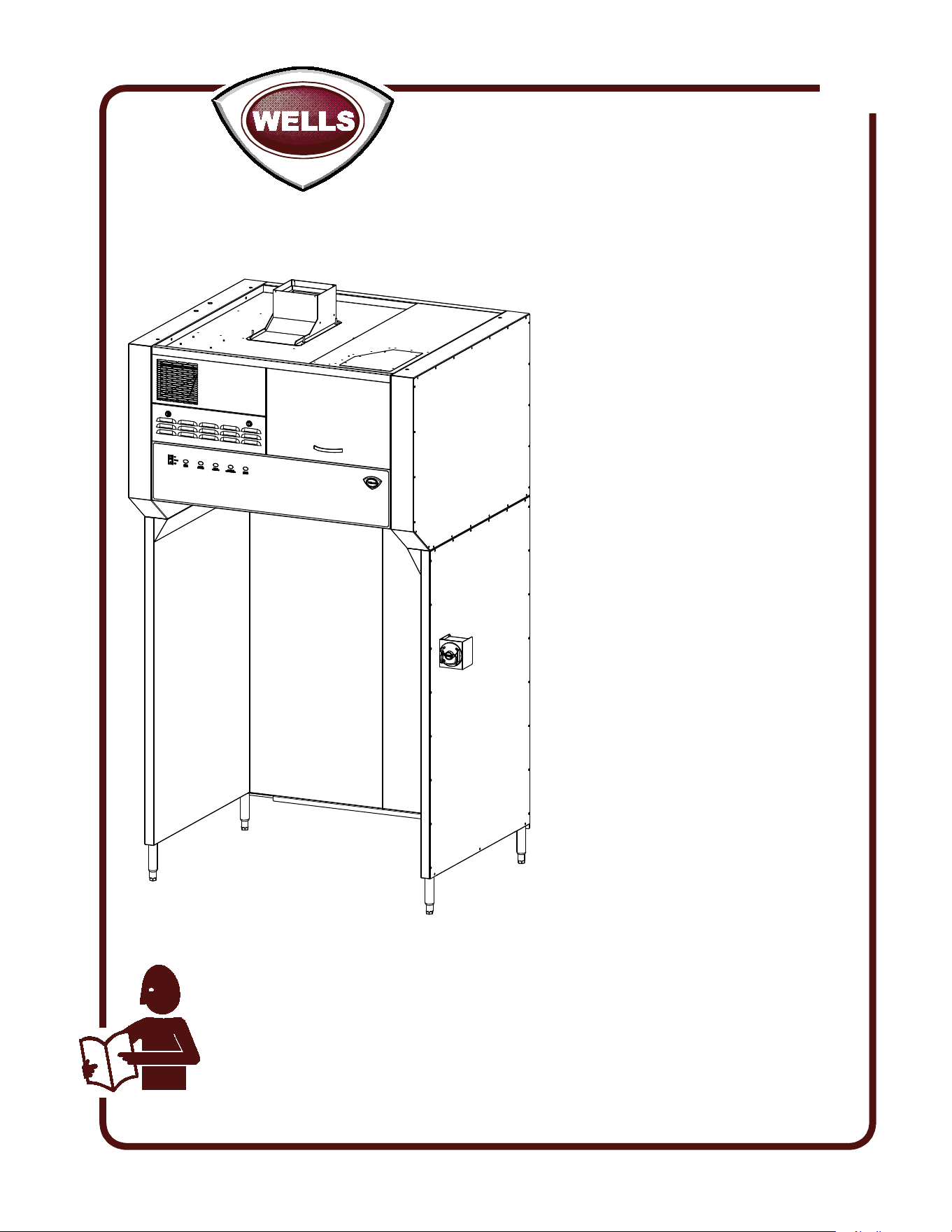
VENTLESS
HOOD SYSTEM
for
ELECTRIC FRYERS &
BROILERS
COOKING
APPLIANCES
MODEL
WV48FB
Manual Includes
INSTALLATION
USE & CARE
EXPLODED VIEW
PARTS LIST
WIRING DIAGRAM
525
2M-Z17944 Rev. B
04/2018
IL2372
WARRA
NTY EXCLUSIONS
THE FOLLOWING WILL NOT BE COVERED UNDER WARRANTY.
• Any product which has not been installed, cleaned, maintained,
or used in accordance with the directions published in the appropriate
installation sheet and/or owner’s manual as well as national and local
codes, including incorrect gas or electrical connection. Wells is not liable
for any unit which has been mishandled, abused, misapplied, subjected
to chlorides, harsh chemicals, or caustic cleaners, damaged from
exposure to hard water, modified by unauthorized personnel, damaged
by flood, fire, or other acts of nature [or God], or which have an altered
or missing serial number.
• Installation, labor, and job checkouts, calibration of heat controls, air
and gas burner/bypass/pilot adjustments, gas or electrical system
checks, voltage and phase conversions, cleaning of equipment,
or seasoning of griddle surface.
• Replacement of fuses or resetting of circuit breakers, safety controls,
or reset buttons.
• Replacement of broken or damaged glass components, quartz heating
elements, and light bulbs.
• Labor charges for all removable parts in gas charbroilers and hotplates,
including but not limited to burners, grates, and radiants.
• Any labor charges incurred by delays, waiting time, or operating
restrictions that hinder a service technician’s ability to perform service.
• Parts that fail or are damaged due to normal wear or labor for
replacement of Items that can easily be replaced during a daily cleaning
routine. such as but not limited to silicone belts, PTFE non-stick sheets,
knobs, control labels, bulbs, fuses, quartz heating elements, baskets,
racks, and grease drawers.
• Components that should be replaced when damaged or worn, but have
been field-repaired instead [eg. field-welded fry pots].
• Any loss of business or profits.
ADDITIONAL WARRANTIES
Specialty/chain specific versions may also have additional and/or
extended warranties.
LIMITED EQUIPMENT WARRANTY
Wells Manufacturing warranties new products to be free from defects
in material and/or workmanship for a period of one [1] year from the
date of original installation, except as noted below. Defects that occur
as a result of normal use, within the time period and limitations defined
in this warranty, will at Wells’ discretion have the parts replaced or
repaired by Wells or a Wells-authorized service agency.
THIS WARRANTY IS SUBJECT TO ALL LISTED CONDITIONS.
Repairs performed under this warranty are to be performed by a Wells-
authorized service agency. Wells will not be responsible for charges
incurred or service performed by non-authorized repair agencies.
In all cases, the nearest Wells-authorized service agency must be used.
Wells will be responsible for normal labor charges incurred in the repair
or replacement of a warrantied product within 50 miles (80.5 km) of
an authorized service agency. Time and expense charges for anything
beyond that distance will be the responsibility of the owner. All labor
will need to be performed during regular service hours. Any overtime
premium will be charged to the owner. For all shipments outside the
U.S.A. and Canada, please see the International Warranty for specific
details.
It is the responsibility of the owner to inspect and report any shipping
damage claims, hidden or otherwise, promptly following delivery.
No mileage or travel charges will be honored on any equipment that is
deemed portable. In general, equipment with a cord and plug weighing
less than 50 lb. (22.7 kg) is considered portable and should be taken or
shipped to the closest authorized service agency, transportation prepaid
.
CONTACT
Should you require any assistance regarding the operation or
maintenance of any Wells equipment; write, phone, fax or email
our service department. In all correspondence mention the
model number and the serial number of your unit, as well as
the voltage or type of gas you are using.
Business hours are 8:00 a.m. to 4:30 p.m. Central Standard Time
Telephone 314.678.6314
Fax 314.781.2714
Email customerservice@star-mfg.com
www.wells-mfg.com
PRODUCTS PARTS LABOR
universal ventless hoods 2 years 1 year
canopy hoods 2 years 1 year
“Cook’n Hold” equipment [HW10,
HWSMP, LLSC7, LLSC7WA, LLSC11,
and LLSC11WA]
2 years 1 year
cast iron grates, burners, and burner
shields
1 year
original Wells parts sold to repair
Wells equipment
90 days
Service First 1 year
The foregoing warranty is in lieu of any and all other warranties expressed or implied and constitutes the entire warranty. 2M-Z22393 • Rev A • 02.2018
M525 p/n 2M-Z17944 OpM WV48FB- Fryer & Broiler Ventless Hood
1
WARRANTY
ELECTRICAL SPECIFICATIONS 1
FEATURES & OPERATING CONTROLS 2-3
PRECAUTIONS & GENERAL INFORMATION 4
AGENCY LISTING INFORMATION 5
INSTALLATION
Unpacking & Inspection 5
Components 5
Under-Hood Appliance Limitations 6
Service Technician Installation Notes 7
Base Assembly 8-9
Electrical Installation 10-11
ANSUL® INSTALLATION & SETUP 12-13
Filter Installation 14
OPERATION
Operation Lights 15
CLEANING INSTRUCTIONS 16-17
WIRING DIAGRAM 19
REQUIRED MAINTENANCE & MAINTENANCE LOGS 20-23
TROUBLESHOOTING SUGGESTIONS 24
EXPLODED VIEW & PARTS LIST 27-36
Thank You for purchasing this Wells Manufacturing appliance.
Proper installation, professional operation and consistent maintenance of this appliance will ensure
that it gives you the very best performance and a long, economical service life.
This manual contains information and instructions for the ventless ventilation hood, its use and care.
For information regarding cooking appliance(s), please refer to the manufacturer’s operation manual.
TABLE OF CONTENTS
ELECTRICAL SPECIFICATIONS
INTRODUCTION
Model Volts Amps Power Supply
WV48FB
208/240V
3.5
For supply connection use #12 AWG copper wire only.
WV48FB-50HZ 4.3
M525 p/n 2M-Z17944 OpM WV48FB- Fryer & Broiler Ventless Hood
2
FEATURES & OPERATING CONTROLS
VENTILATOR CONTROL PANEL
see page 15
IL2391a
12
11
13
14
25
26
20
19
15
24
10
9
43 5 6
7
8
16
17
2
22
23
21
1
18
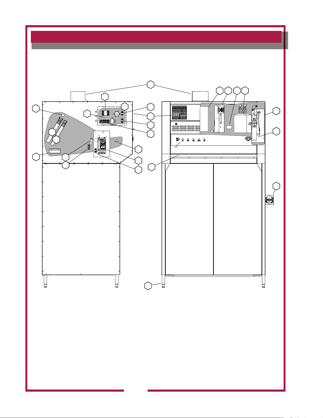
Ventilator Section Operating Features & Controls
M525 p/n 2M-Z17944 OpM WV48FB- Fryer & Broiler Ventless Hood
3
FEATURES & OPERATING CONTROLS continued
FEATURES & OPERATION CONTROLS
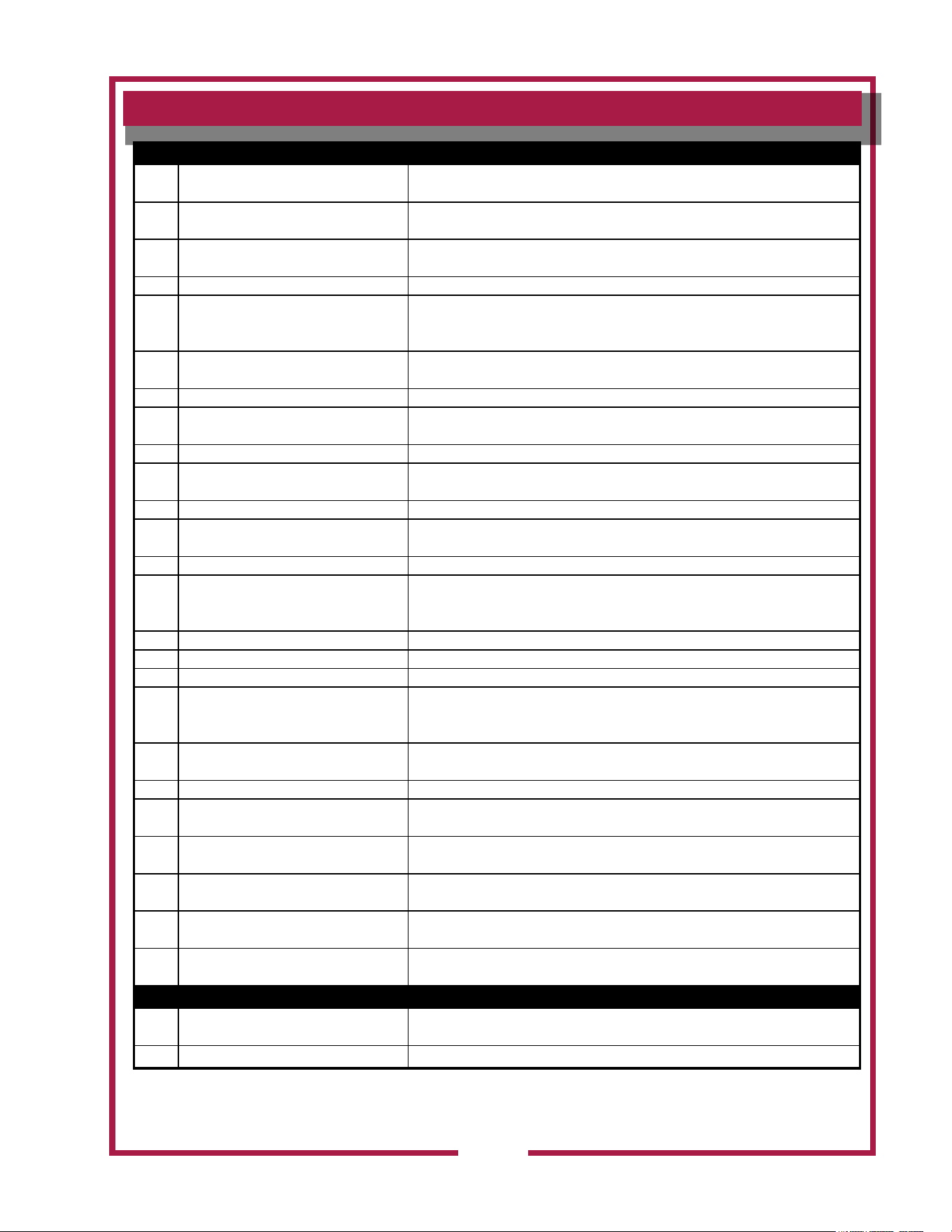
ITEM
NO
DESCRIPTION COMMENT
1 VENTILATOR EXHAUST DUCT, TOP Exit point for ventilator airow - on top of unit. DO NOT BLOCK
2 VENTILATOR EXHAUST DUCT, FRONT Exit point for ventilator airow - on front of unit. DO NOT BLOCK
3 VENTILATOR FAN Provides air movement for ventilation
4
HI-EFFICIENCY/CHARCOAL FILTER
PACK
Removes grease and smoke particles. Also assists in cooking odor removal.
5 NAMEPLATE
Gives manufacturer, make and model description. Also list voltage and amperage
data.
6 FIRE SUPPRESSION TANK Container for ANSUL® Low-pH Liquid re suppression uid.
7 ACTUATOR ASSY
Triggers deployment of suppression uid through manual pull station or electric
detection.
8 ANSUL® CARTRIDGE Propels suppression liquid through suppression manifold and nozzles.
9 MANUAL PULL STATION
Provides a means of manual activation of the re suppression system. PULL ONLY
IN CASE OF FIRE!
10 ADJUSTABLE LEGS Allows the unit to be leveled.
11 AIR WALL A wall of air that moves the grease and smoke particles into the lter system.
12 DISCHARGE NOZZLES Fire suppression media discharges here, (6 places 48”, 12 places 96”)
13 ELECTRICAL DETECTORS
Designed to activate at certain temperature. Activates (i.e. re on the cooktop)
activates re suppression system. Should be checked every 6 months during
ANSUL® Service Inspection
14 APPLIANCE LIGHT ON when hood power switch is ON. Illuminates cooking area.
15 GREASE DRIP TRAY Collects grease/moisture dripping from bafe lter (16)
16 BAFFLE FILTER Extracts and drains most greases and moisture from the air ow.
17 PRE-FILTER ASSEMBLY
Comprises the PRE-FILTER FRAME and a replaceable PRE-FILTER. Stops large
particles of grease from reaching the FILTER PACK for reduced maintenance costs.
18 ELECTRICAL CONNECTION BOX Houses electrical components
19 GROUND LUG Ground wire of power connection connects here.
20 EQUIPMENT INTERFACE CONTACTOR Energizes cooking appliances only while ventilator section is sensed as operational.
21 BUILDING FIRE ALARM RELAY Reports re alarm condition to building re management system.
22 DETECTION END OF LINE RELAY Prevents appliance operation if a fault is found in detection circuit.
23
SUPPLY CONNECTION TERMINAL
BLOCK
Provides connection point for electrical circuitry
24 FILTER INTERLOCK SWITCHES
Proper installation of bafe lter and lter pack closes these switches in ventilator
sensor circuit
50Hz UNITS
25 VARIABLE FREQUENCY DRIVE Converts 50Hz to 60Hz, 1 Phase
26 VFD RELAY Engauges VFD
M525 p/n 2M-Z17944 OpM WV48FB- Fryer & Broiler Ventless Hood
4
PRECAUTIONS AND GENERAL INFORMATION
This ventilator hood is part of an engineered system and is intended for
use in commercial establishments only.
This ventilator is intended
for commercial establishments for use
in the preparation food for human consumption. No other use is
recommended or authorized by the manufacturer or its agents.
Operators of this appliance must be familiar with the appliance use,
limitations and associated restrictions. Operating instructions must be
read and understood by all persons using or installing this appliance.
This ventilator hood system is designed to reduce odor emissions,
but will not completely eliminate all cooking odors. Air exchange
rates at the installation site must comply with the requirements of the
local jurisdictional authority. To ensure that odors do not accumulate,
recommended minimum air exchange is 200 cfm per linear foot of hood
into and out of the site.
This unit is intended for use with light- and medium duty electric
cooking appliances only. Cooking appliances placed under this
ventilator must comply with the restrictions set forth in the Installation
section of this manual.
Do not connect or energize this appliance until all installation
instructions are read and understood. Property damage or bodily
injury may result if these instructions are not followed. Disconnect this
appliance from electrical power before performing any maintenance or
servicing.
Cleanliness of this appliance is essential to good sanitation. Read and
follow all included cleaning instructions and schedules to ensure the
safety of the food product.
This appliance is not jet steam approved. Do not direct water jet or
steam jet at this appliance, or at any control panel or wiring.
Do not splash or pour water on, in or over any controls, control panel or
wiring. Do not attempt to wash lter packs. Water will cause their
immediate failure and disable the ventilator.
Exposed surfaces of this appliance can be hot to the touch and may
cause burns.
Avoid storing ammable or combustible materials in, on or near the
ventilator or associated cooking appliance.
The technical content of this manual, including any wiring diagrams,
schematics, parts breakdown illustrations and/or adjustment
procedures, is intended for use by qualied technical personnel.
Any procedure which requires the use of tools must be performed by a
qualied technician.
All supplied instructions, diagrams, schematics, parts breakdown
illustrations, notices and labels must remain with the appliance if the
unit is sold or moved to another location.
This appliance is made in the USA. Unless otherwise noted, this
appliance has American sizes on all hardware.
DANGER:
SUFFOCATION HAZARD
Do not attempt to use this
ventilator with gas-red units.
This ventilator will not remove
products of combustion.
Unvented exhaust gasses
can be deadly.
WARNING:
SHOCK HAZARD
All servicing requiring
access to non-insulated
electrical components must
be performed by a factory
authorized technician.
DO NOT open any access
panel which requires the use
of tools. Failure to follow this
warning can result in severe
electrical shock.
IMPORTANT:
The ventilator is disabled
when the lters are plugged
to the point of insufcient
airow for proper operation.
Also, power to the cooking
appliances is interrupted if
any lters or service panel
are removed.
It is the responsibility of
the store management to
maintain sufcient spares
of lter packs to avoid
prolonged shutdown due
to a dirty or clogged lter
pack. Filter packs cannot be
cleaned.
Wells Manufacturing
assumes no liability for loss
of business due to a lter
related shutdown. Spare
lters can be purchased
from any authorized Wells
servicer or calling Wells.
M525 p/n 2M-Z17944 OpM WV48FB- Fryer & Broiler Ventless Hood
5
AGENCY LISTING INFORMATION
INSTALLATION
NOTE: DO NOT discard
the carton or other packing
materials until you have
inspected the appliance for
hidden damage and tested it
for proper operation.
Refer to SHIPPING DAMAGE
CLAIM PROCEDURE on the
inside front cover of this
manual.
WARNING:
RISK OF INJURY
Installation procedures must
be performed by a qualied
technician with full knowledge
of all applicable electrical
codes. Failure can result in
personal injury and property
damage.
IMPORTANT:
Fire suppression system must
be charged and certied by an
authorized Ansul® distributor.
Ventilator will not operate and
cooking appliance will not be
energized until the Ansul® re
suppression system has been
charged.
IMPORTANT:
After cooking appliances
are positioned under the
hood, swivel nozzles must
be positioned per Ansul®
recommendations.
UNPACKING & INSPECTION
Carefully remove the appliance from the carton. Remove all
protective plastic lm, packing materials and accessories from the
appliance before connecting electrical power or otherwise performing
any installation procedure.
Carefully read all instructions in this manual and any other documents
packed with the appliance before starting any installation.
All documentation should remain with the equipment operator for future
reference.
Read and understand all labels and diagrams attached to the
ventilator.
Carefully account for all components and accessories before
discarding packing materials.
COMPONENTS
4 ft
Pre-Filter 2 ea.
Bafe Filter 2 ea.
Filter pack 1 ea.
Grease cup 1 ea.
Ansul® components - must be installed by an authorized Ansul®
distributor only:
4 ft
2 ea. Fire suppression agent tank
2 ea. Fire suppression agent (Ansulex® Low pH) 1.5 gal.
1 ea. Fire suppression system charging cartridge
Store these components in a convenient place for later use.
The unit is shipped congured for horizontal discharge of the exhaust.
To convert to vertical discharge:
1. Remove top access cover.
2. Remove internal turning vane.
3. Insert top discharge scoop assy and fasten w/hardware from cover.
4. Remove front discharge vent panel and damper assy.
5. Assemble damper in Top discharge scoop assy.
6. Replace front discharge vent panel.
This appliance conforms to NSF Standard 2 for sanitation only if
installed in accordance with the supplied Installation Instructions
and operated and maintained in accordance with the instructions in this
manual.
UL CLASSIFIED for use in US and Canada
UL710B
Recurculating System
SANITATION
NSF/ANSI 2
M525 p/n 2M-Z17944 OpM WV48FB- Fryer & Broiler Ventless Hood
6
INSTALLATION (continued)
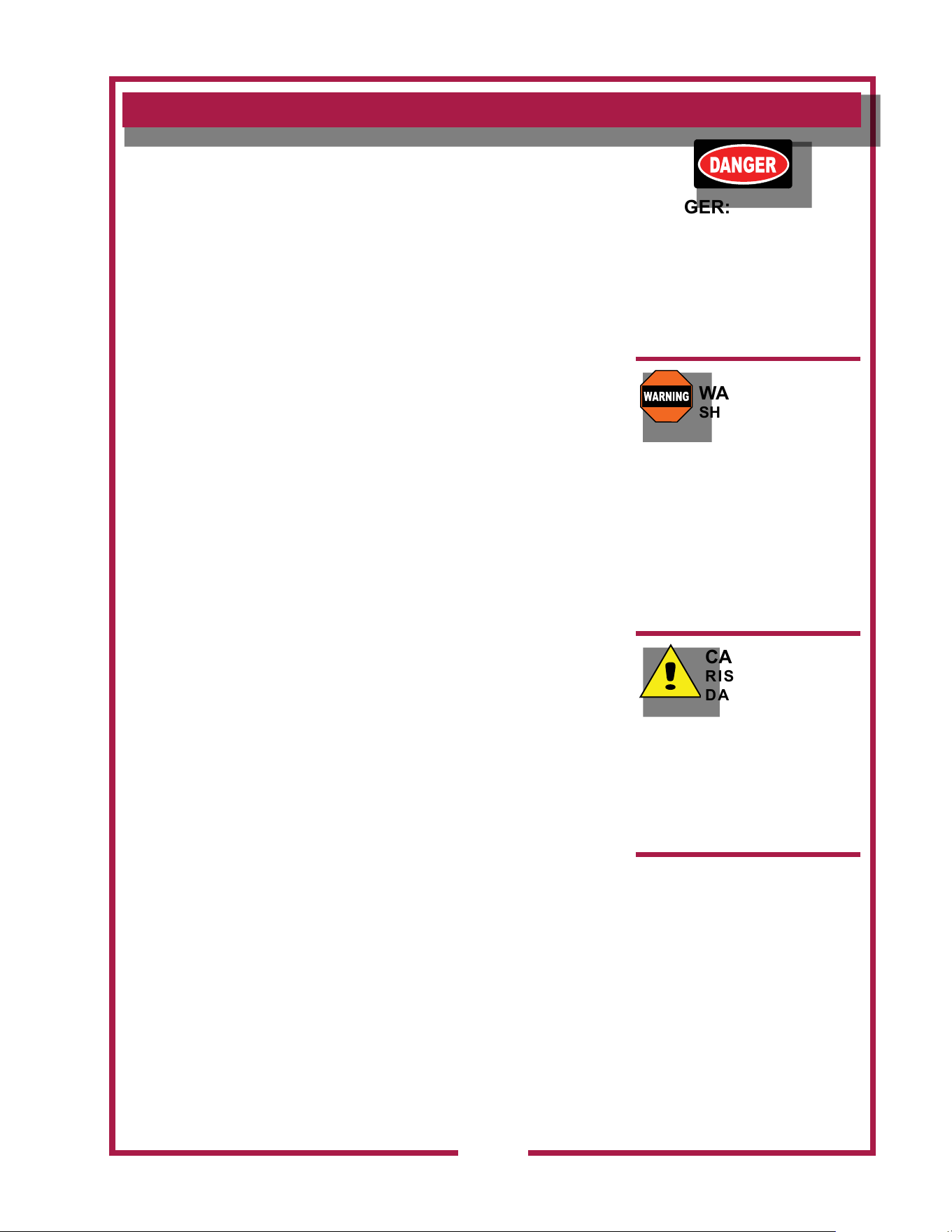
UNDER-HOOD APPLIANCE LIMITATIONS:
COOKING APPLIANCE LIMITATIONS
Acceptable Appliances by
Appliance Type
kW / Ft
Max
Max
Cooking
Temp
Max Single
Heated Surface
Length
Dim
“A” (2)
Minimum
Dim
“B” (3)
Minimum
Dim
“B” (3)
Maximum
Dim
“C” (4)
Minimum
Single Vat Fryer
16.9
400°F
(204°C)
18
14 37 42
0
Multi Vat Fryer
48
0
Oven/Convection Oven
N/A
550°F
(287°C)
6 8 N/A
0
Steamer / Combi Oven 0
(1) Maximum single width 18”
(2) Front of hood to front edge of heated cooking surface.
(3) Bottom front edge of hood to height of heated cooking surface.
(4) Clearance from hood side panel to heated cooking surface.
(5) Model JF91E with electrically interlocked exhaust catalyst.
(6) Meat paties must be frozen.
(7) Front edge of hood to front edge of heated chamber.
(8) Bottom edge of hoot to exhaust catayst.
(9) Clearance from hood side panel to broiler side.
All under hood appliances must be controlled by the equipment shutoff
interface. See owners manual pages 10-11 and wire diagram in supply
connection box. Only electrically heated appliances are acceptable for
installation. Appliance operation requires the re suppression system
be setup, charged and certied by an Authorized Ansul® Distributor.
The airow monitoring system will prevent appliance operation if
insufcient airow is detected or all lters are not in place.
The service panel must be in place for blower operation.
This hood and all under hood appliances must be installed in
accordance with the standard for ventilation control and re protection
of commercial cooking operations NFPA 96. The national electrical
code NFPA70 and all local codes where applicable.
Wells Manufacturing Model WV48FB
Lower Airow Limit: 1500 CFM
Broiler Maximum Measured Grease Emissions: 0.0063 LBS/HR/FT
Other Accepted Appliances: 0.0024 LBS/HR/FT
ANSI-UL710B Recirculating System UL Category YZCT FILE NO. MH4808
E
48"
74”
D
A
48"
74
B
BY APPLIANCE TYPE
NIECO MODEL JF91E
IL2744
* The 10” - 12” leg option
increases the overall vertical
height.
SPECIFIC APPLIANCE LIMITATIONS
Specic Appliance
see notes (5) (6)
Input
Max
Max Temp
Setting
Dim D
Min (7)
Dim E
Min (8)
Dim E
Max (8)
Dim F
Min (9)
NIECO Conveyor Broiler 7 Kw 500 15 14.5 18 0
M525 p/n 2M-Z17944 OpM WV48FB- Fryer & Broiler Ventless Hood
7
INSTALLATION (continued)
SERVICE TECHNICIAN INSTALLATION NOTES
This ventilator hood is to be used with light-duty and medium-duty
electrically powered cooking appliances only.
• DO NOT attempt to use this ventilator hood with gas-red units.
• DO NOT use this ventilator hood with electrical appliances whose
dimensions or wattage characteristics exceed those dened in the
Under Hood Cooking Appliance Limitations, page 6.
Installation and start up must be performed by an Authorized
Installation Company.
Ansul® Installer must complete the WARRANTY INITIATION form
(2M-303912) included with the unit for the warranty to begin, and record
installation particulars on the CUSTOMER SERVICE DATA form
located at the end of this manual.
IT IS THE RESPONSIBILITY OF THE INSTALLER TO verify that this
VENTILATOR installation is in compliance with the specications listed
in this manual, with local code requirements, and in accordance with
NFPA 96 the STANDARD FOR VENTILATION CONTROL AND FIRE
PROTECTION OF COMMERCIAL COOKING OPERATIONS.
NOTE: Certain codes require FRYERS to be restrained with a
TETHER or other RESTRAINT DEVICE. If this ventilator is to be used
with a fryer, it is the RESPONSIBILITY OF THE INSTALLER to check
with the AUTHORITY HAVING JURISDICTION, in order to ascertain
the applicability of this requirement to this specic installation .
SETUP
Setup the appliance only on a rm, level, non-combustible surface.
Verify local codes for requirements. Concrete, tile, terrazzo or metal
surfaces are recommended. Metal over combustible material may not
meet code for non-combustible surfaces.
Verify vertical clearances. Ceiling height shall be no less than 103”
inches when utilizing horizontal discharge option. Ceiling height shall
be no less than 120” inches when utilizing vertical discharge option.
Verify that the unit sits rmly on ALL LEGS. With a spirit level, check
that the appliance is level front-to-back and side-to-side. With the
adjustable legs, adjust as required to level the appliance. In order to
prevent tipping or deection, legs must be adjusted such that all legs
are in rm contact with the oor.
WARNING:
Equipment must be installed in accordance with the equipment
parameters table located on the service door. Fire suppression
sensors used on this unit provide superior re detection but are
sensitive to rapid temperature rise. To prevent unintentional
deployment of the re extinguishing system,
DO NOT move equipment from installed position when in use.
DO NOT power off hood when under hood equipment is HOT.
DANGER:
SUFFOCATION HAZARD
Do not attempt to use this
ventilator with gas-red units.
This ventilator will not remove
products of combustion.
Unvented exhaust gasses
can be deadly.
WARNING:
SHOCK HAZARD
All servicing requiring
access to non-insulated
electrical components must
be performed by a factory
authorized technician.
DO NOT open any access
panel which requires the use
of tools. Failure to follow this
warning can result in severe
electrical shock.
CAUTION:
RISK OF
DAMAGE
DO NOT connect or energize
this appliance until all
installation instructions are
read and followed. Property
damage or bodily injury could
result if these instructions are
not followed.
IMPORTANT:
If a remote pull station is to
be used, ventilator cannot be
moved without rst disabling
the remote pull station.
Contact your Ansul® agent
for details.
M525 p/n 2M-Z17944 OpM WV48FB- Fryer & Broiler Ventless Hood
8
INSTALLATION (continued)
Front
Bottom Stiffener
IL2387
Figure 1
Front
IL2388
Figure 2
Corner Bracket
6” Adj. Legs
IL2389
Figure 3
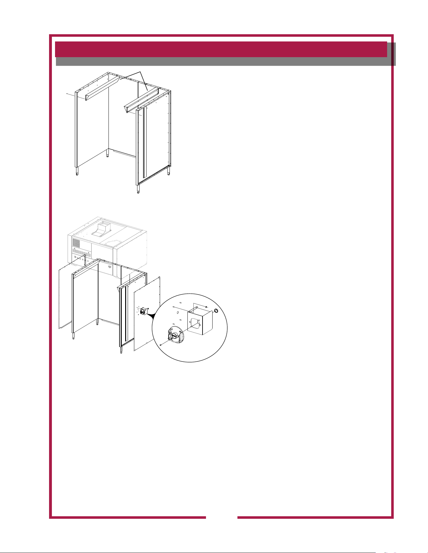
BASE ASSEMBLY
Prior to assembling the base, locate it as close to the
nial position as possible. Then follow these steps.
1. Align the two rear panels (Fig 1) and secure with a
bolt, washer and nut (8 places).
2. Place the Base Bottom Stiffener (N1-Z15330) to the
bottom of the two rear panels and secure with bolt,
washer and nut (8 places).
3. Align the left and right side of the base to the rear
panel (Fig 2) and secure with bolt, washer and nut
(8 places each side).
4. Align the rear corner brackets in place (Fig 3) and
secure with bolt, washer and nut
(4 places each bracket).
5. Install the 6” adjustable legs and secure in place with
the bolt provided.
Hardware Provided
IL2977
Nut; 2C-6517
Washer; 2C-A27469
Bolt; 2C-Z5555
M525 p/n 2M-Z17944 OpM WV48FB- Fryer & Broiler Ventless Hood
9
INSTALLATION (continued)
Base Deflectors
Figure 4
IL2743
Figure 5
6. Align the two base deectors (Fig 4) in place and
secure with screws (8 per deector)
7. Move the base into position, and using a level,
adjust the legs until level.
8. Remove the side panels of the hood assembly so
when lowered onto the base assembly it will be
easier to secure in place.
9. Using the upper supporting brackets on the hood,
lower the hood on top of the base (Fig 5) so the
mounting holes line up. Secure with bolt, washer
and nut (7 places each side).
10. Contact your electrical & Ansul® contractors
to provide service to the system. Refer to
the ELECTRICAL INSTALLATION &
FIRE
SUPPRESSION SYSTEM INSTALLATION
sections in this manual.
11. Once complete the side panels can be installed
using hardware provided.
M525 p/n 2M-Z17944 OpM WV48FB- Fryer & Broiler Ventless Hood
10
TB1
TB6
TB7
TB8
TB2
TB3
TB4
TB5
LINE INPUT
208-240VAC
50/60HZ
BUILDING
ALARM
INTERFACE
TO CUSTOMER
SUPPLIED
SWITCHING
DEVICE (SPST)
OPTION 2
TO CUSTOMER
SUPPLIED APPLIANCE
CONTACTOR
(240V CNTR CIRCUIT)
OPTION 1
L1 L2
IL2376a
TB3
TB4
208/240V
APPLIANCE
CONTROL
EQUIPMENT
CUTOFF
TERMINALS
CUSTOMER
SUPPLIED
CONTACTOR(S)
TO APPLIANCE
OVER CURRENT
PROTECTED
SUPPLY
EQUIPMENT INTERFACE OPTION 1
SPST
SWITCHED
EQUIPMENT
CUTOFF
TERMINALS
TB5
TB6
CUSTOMER
SUPPLIED
CONTACTOR(S)
CUSTOMER
SUPPLIED
SOURCE CIRCUIT
TO APPLIANCE
OVER CURRENT
PROTECTED
SUPPLY
L3
T3
EQUIPMENT INTERFACE OPTION 2
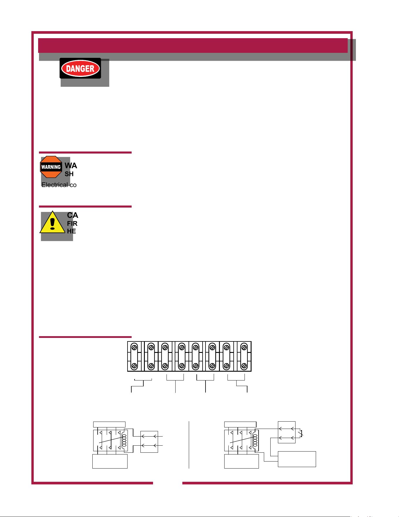
ELECTRICAL INSTALLATION
Refer to the nameplate on the ventilator. Verify ELECTRICAL
SERVICE POWER. Voltage and phase must match the nameplate
specications, and available electrical service amperage must meet or
exceed the listed amperage. Refer to specications listed on page 1 of
this manual.
The ground lug of this ventilator must be connected to a suitable
building ground.
Remove the left side panel to access the cooking appliance contactor
and building alarm relay. Remove the appropriate knockout, then wire
the cooking appliance control circuit to the terminal block per Fig below.
NOTE: It is the responsibility of the electrical contractor to provide
suitable wiring, exible or rigid conduit, and an appropriate strain relief.
Electrical Connection
NOTE: The hood requires a single phase (1ph), 208 or 240 volt, 20
amp supply. When connecting line voltage to the unit’s terminal block,
use a minimum of #12 gage copper wire only, suitable for 167°F (76°C)
ambient temperature.
Appliance Connections
All under hood appliances are required to be interlocked with the hood’s
equipment cut-off circuit, through a customer supplied contactor. This
contactor must be a UL listed, denite purpose AC resistive air heating type,
suitable for the appliance load. Installation and connections shall be in
accordance with the National Electric Code NFPA 70. These connections
provide an automatic shutdown of the appliance when the hood is OFF, or in
the event of a malfunction or appliance re.
Equipment Cutoff Connections
Opt 1: Use TB#3 & TB#4 for 208 or 240 volt control circuit. These contacts will be
de-energized when the hood is OFF or in the event of a malfunction
Opt 2: Use TB#5 & TB#6 as a Normally Closed SPST relay connection for equipment
control circuits with voltages other than 208 or 240 AC. These contacts will be
open when hood is OFF or in the event of a malfunction.
INSTALLATION
DANGER:
SUFFOCATION HAZARD
Do not attempt to use this
ventilator with gas-red units.
This ventilator will not remove
products of combustion.
Unvented exhaust gasses
can be deadly.
WARNING
SHOCK HAZARD
Electrical connections must
be made by a licensed
electrician.
CAUTION:
FIRE HAZARD
HEALTH HAZARD
All cooking appliance must
be connected to the cooking
appliance contactor, the
control circuit of which is
controlled by the ventilator.
Failure to control cooking
appliances will provide no
protection in the event of a
re, nor will cooking vapors
and odors be contained in
the event of ventilator hood
malfunction.
M525 p/n 2M-Z17944 OpM WV48FB- Fryer & Broiler Ventless Hood
11
DANGER:
SHOCK HAZARD
Turn power off to the unit
before removing the side
electrical box cover.
CAUTION:
SHOCK HAZARD
The ground lug of this
appliance must be connected
to a suitable building ground.
IMPORTANT:
Contact a licensed electrician
to install and connect electrical
power to the appliance.
IMPORTANT:
Damage due to being
connected to the wrong
voltage or phase is NOT
covered by warranty.
INSTALLATION continued
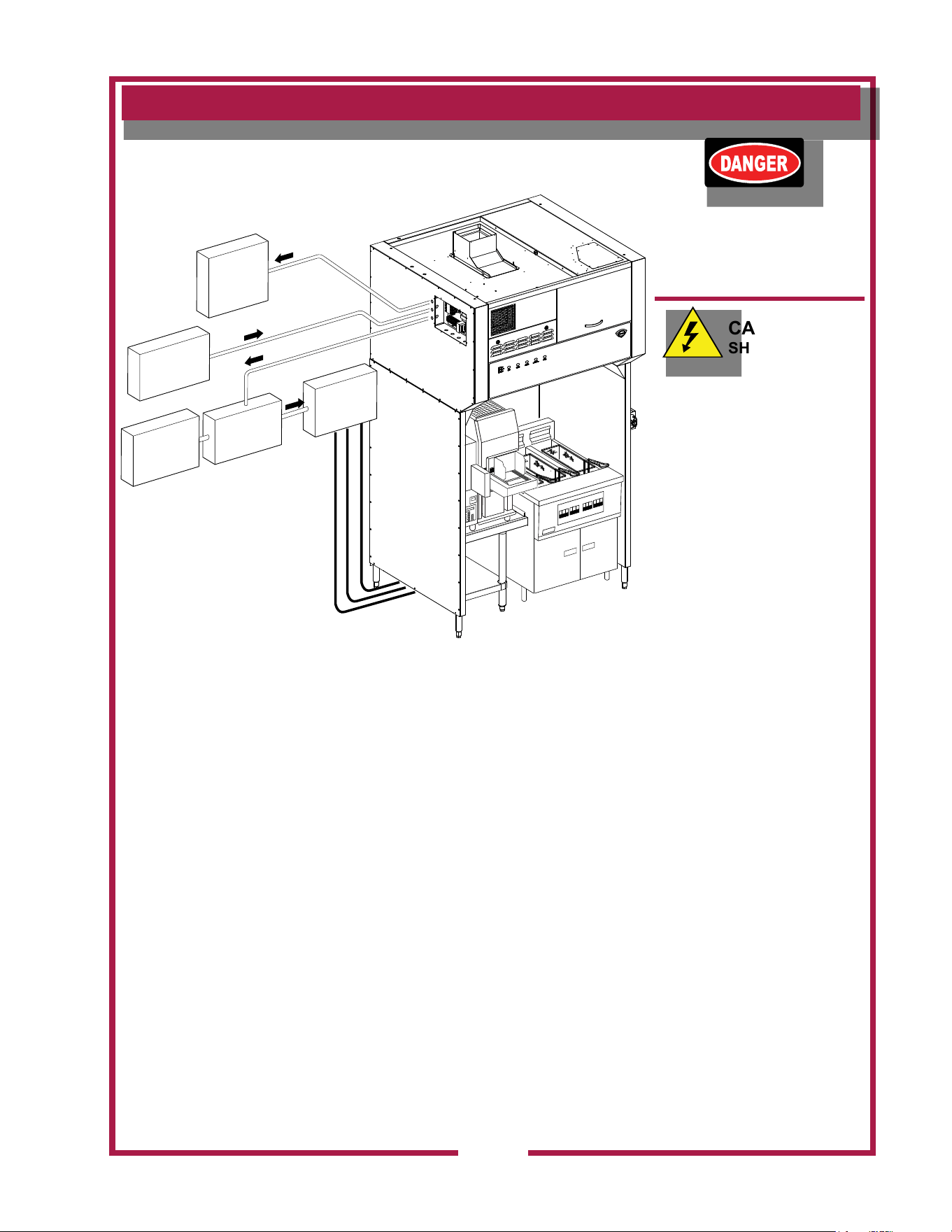
SUPPLY POWER INSTALLATION
IL2745
FIRE
ALARM
SYSTEM
SUPPLY
POWER
TO HOOD
APPLIANCE(S)
POWER
SUPPLY
HOOD
INTERFACE
CONTACTOR(S)
POWER
TO
APPLIANCE(S)

M525 p/n 2M-Z17944 OpM WV48FB- Fryer & Broiler Ventless Hood
12
INSTALLATION continued
DANGER
FIRE HAZARD
Fire suppression system
must be charged and certied
by an authorized Ansul®
distributor.
DO NOT attempt to modify or
bypass the re suppression
system.
An uncontrolled re can
cause serious injury or death.
NOTE:
If the re suppression system
is discharged, a buzzer will
sound continuously. The unit
will remain inoperable until
the re suppression system is
serviced, recharged and reset
by an authorized Ansul®
distributor.
Charging of the Ansul®
Fire Suppression system
must be in accordance with
Ansul® Design, Installation,
Recharge and Maintenance
Manual, #418087.
NOTE:
If a REMOTE MANUAL PULL
STATION is installed, moving
the ventilator for any reason
may cause the Ansul®
system to discharge.
IMPORTANT:
Should the re suppression
system discharge: all nozzles
must be replaced, and all
lines thoroughly cleaned,
prior to recharging the
system.
Residual re suppression
media may compromise the
ow and dispersion of re
suppression media in any
subsequent activation.
The alarm relay is activated by the Ansul® re detection system. If the
installation includes a building alarm system, connect to terminals T7 &
T8 of the terminal block in supply connection box. These terminals are
congured from the factory for normally open operation.
The ventilator will operate properly, and the appliance control relay will
be energized, only when:
1. The VENTILATOR POWER SWITCH is “ON”.
2. The Ansul® Fire Suppression System is charged and armed.
3. All lters are in position and serviceable, and the ventilator air ow
system is satised.
FIRE SUPPRESSION SYSTEM INSTALLATION
THE FIRE SUPPRESSION SYSTEM is comprised of two containers
of Ansulex® Low pH liquid re suppression media and a system
pressurization canister, plus associated plumbing.
The hood is supplied with a eld installed MANUAL PULL STATION,
which must be set-up at the time of installation by an authorized Ansul®
distributor.
The MANUAL PULL STATION allows for manual emergency
shutdown of cooking appliance power, and actuation of the re
suppression system.
Six NOZZLES disperse the re suppression media. Two inner nozzles
protect the fan and plenum.
The appliance nozzles are swivel mounted,
and must be directed toward the cooking surface of the installed
cooking appliance.
If the ventilator is situated such that the supplied manual pull
station cannot be installed or is not readily accessible, a REMOTE
MANUAL PULL STATION may be required by local codes. Any
such remote manual pull station must be installed by an authorized
Ansul® distributor in accordance with the AUTHORITY HAVING
JURISDICTION.
The re detection system utilizes six electronic thermal detectors with
an actuation set point of 225°F (107°C) in the upper hood locations
and 275°F (135°C) detectors in the lower wall locations. The signaling
from any of these detection devices will automatically discharge the re
suppression media through all nozzles, disable the cooking appliances
and cause the alarm to sound.
Fire suppression media will form an emulsion designed to both smother
and cool the fuels in/on the cooking appliance.

M525 p/n 2M-Z17944 OpM WV48FB- Fryer & Broiler Ventless Hood
13
INSTALLATION
DANGER
BURN HAZARD
Any additional remote pull
station must NOT be installed
on the front of the cooking
appliances,
Discharge of the re
extinguishing system into hot
grease or oil may cause hot
foam to spill over from the
cooking surface or frypot.
Serious burns and other injuries
can result from contact with hot
oil and from slipping in spilled
oil.
The manual pull station is
installed on the right side
(facing the unit. It may,
however, be relocated to the left
side of the ventilator hood by an
authorized Ansul® agent.
IMPORTANT:
Equipment must be installed
in accordance with the
equipment parameters table
located on the service door.
Fire suppression sensors
used on this unit provide
superior re detection
but are sensitive to rapid
temperature rise. To prevent
unintentional deployment of
the re extinguishing system,
DO NOT move equipment
from installed position when
in use. DO NOT power
off hood when under hood
equipment is HOT.
FIRE SUPPRESSION SYSTEM INSTALLATION (continued)
The MANUAL PULL STATION and any similar REMOTE MANUAL
PULL STATION will activate the re suppression system when the
ring on the pull station is pulled to its full extent.
M525 p/n 2M-Z17944 OpM WV48FB- Fryer & Broiler Ventless Hood
14
INSTALLATION
NOTE:
The BAFFLE FILTERS,
PRE-FILTERS and FILTER
PACK actuate position
switches when they are
properly positioned. They
must be properly installed
for the under hood cooking
appliance contactor to be
energized.
WARNING
SLIP AND FALL
HAZARD
DO NOT operate any
grease-producing cooking
appliance
(e.g. fryer or broiler) unless
the grease cup is properly
installed. Oil will drip onto
oor creating a slipping
hazard.
CAUTION
BURN HAZARD
DO NOT operate any cooking
appliance unless the grease
cup is installed.
Moisture dripping onto hot
surfaces, oil or grease can
cause splattering.
FILTER INSTALLATION
Note air ow direction arrow on lter pack. Remove old lter pack
and slide new lter pack fully into the appropriate slot. Verify that
the airow arrow points toward the fan.
Bafe lters are reusable and should be cleaned at least weekly.
Change pre-lters and smoke/odor lter pack as indicated on the front
panel. These lters are disposable and cannot be reused. The smoke
/ odor lter pack is accessed thru the front service door.
Pre-lters are located behind the bafe lters, when installing pre-lters
engage top retaining ange prior to seating pre-lter housing in lower
chamber.
Use only genuine Wells replacement parts and lters,
call (314) 678-6314 or your authorized Wells service agent. Parts
supplied by others will void your warranty and may not provide safe
operation.
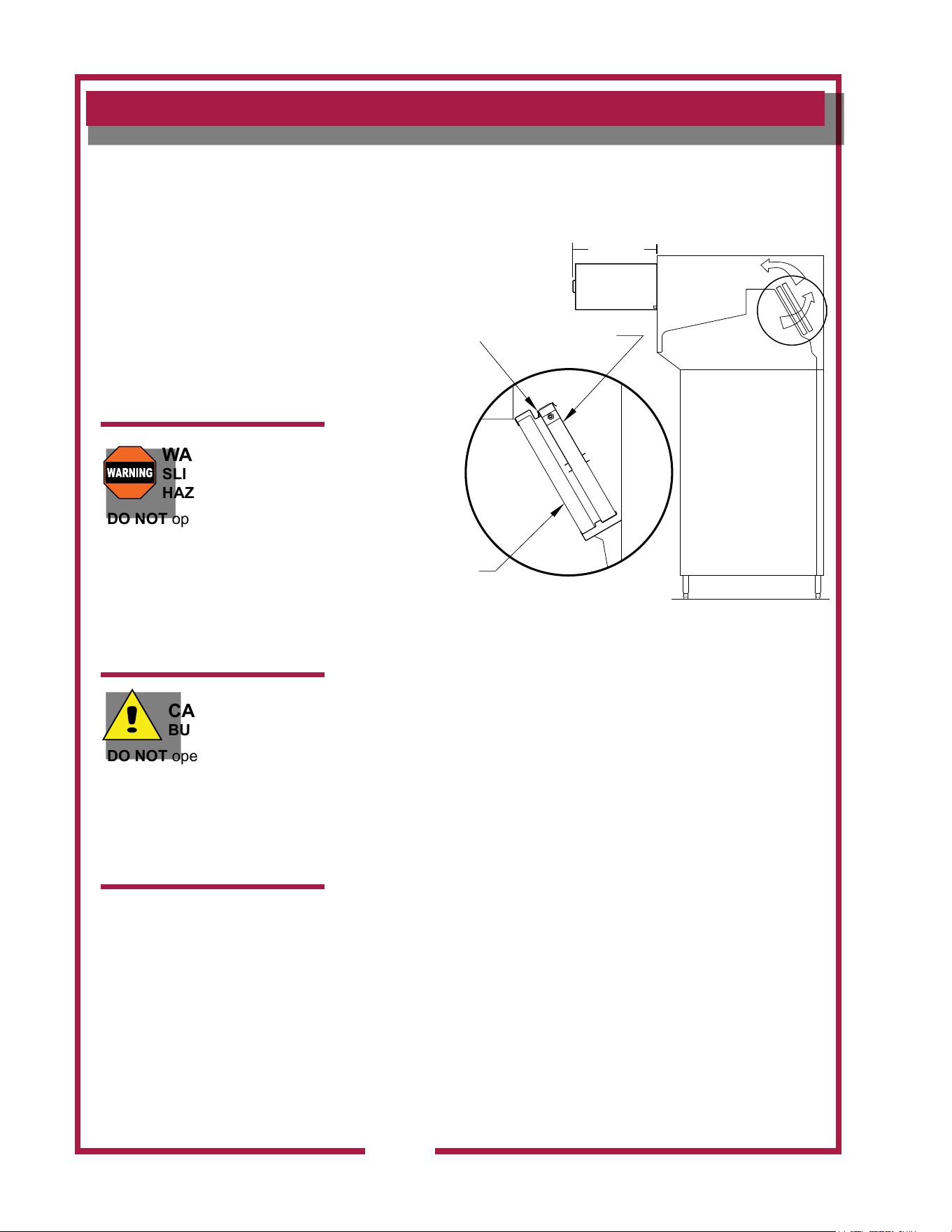
BAFFLE FILTER and GREASE CUP INSTALLATION
1. Install bafe lter from front. Engage the bafe lter in the retainer
slot. Push up until the bafe lter bottom clears the lower lip of the
retainer, then lower the bafe lter into the bottom retainer
2. Install GREASE CUP into brackets below the bafe lter.
Note: Failure to install the GREASE CUP will allow grease and
moisture from the BAFFLE FILTER to drop into hot cooking surfaces,
creating both a SAFETY HAZARD (hot oil splatter) and a HEALTH
HAZARD (contamination of the cooking surface or cooking oil).
SIDE VIEW
SMOKE & ODOR
FILTER PACK
PART NO. WL0171
AIRFLOW
AIRFLOW
IL2377b
25.9 Min
Clearance
PREFILTER HOUSING MUST
HOOK IN FLANGE AT TOP.
CHECK TO MAKE SURE YOU
CANNOT PUSH IT BACK
AFTER INSTALLATION
BAFFLE FILTER
PART NO. 2I-Z14670
PREFILTER
PART NO. 2I-302579
M525 p/n 2M-Z17944 OpM WV48FB- Fryer & Broiler Ventless Hood
15
Control Panel
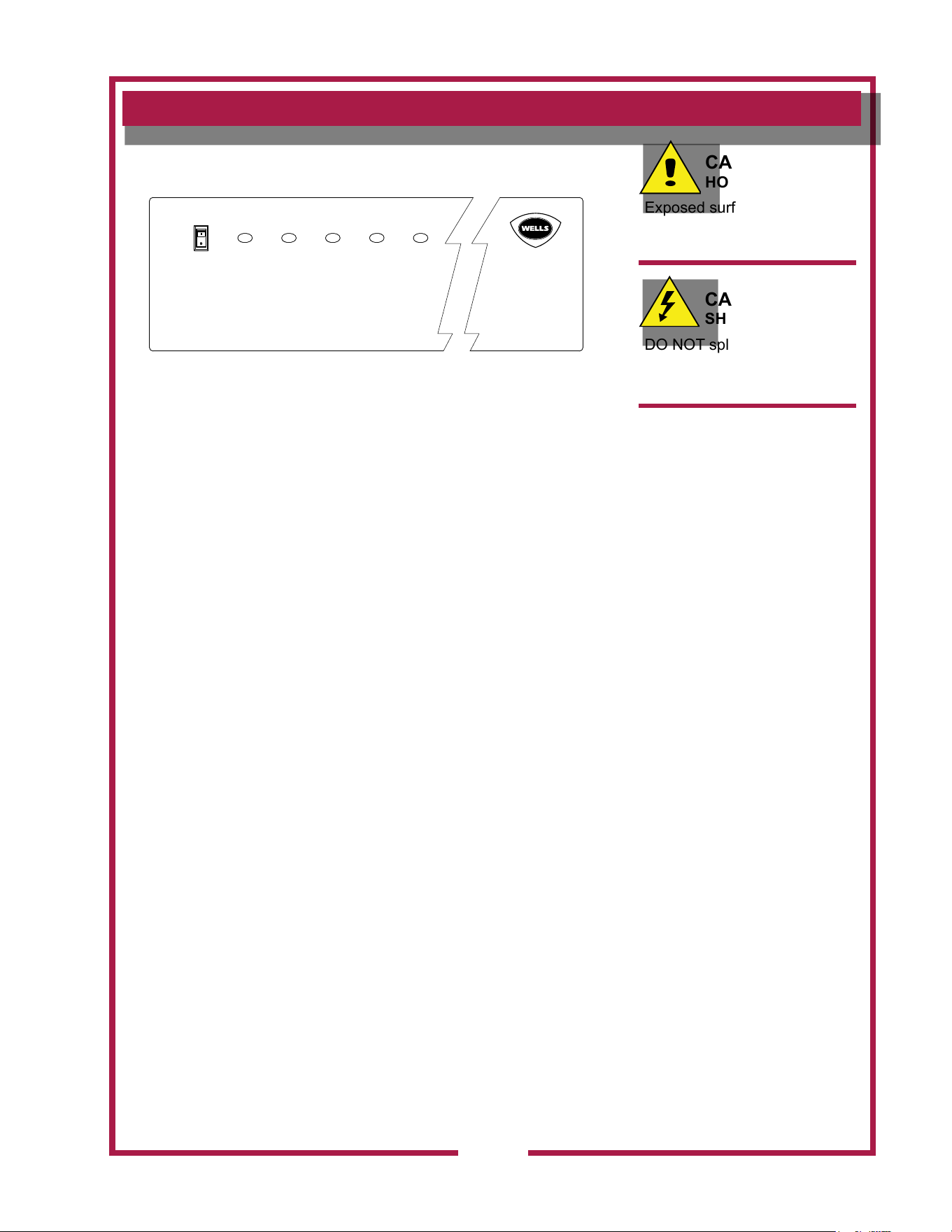
NOTE: Cooking appliances must be operated in accordance with the
manufacturer’s instructions.
During normal operation, the illuminated power switch will be the only
light on the control panel that will be ON.
If the CHECK FILTERS light illuminates, check BAFFLE FILTERS, PRE-
FILTERS, and the HEPA AIR FILTERS for proper installation.
If the REPLACE PRE-FILTERS light illuminates .. Replace the Pre-lters.
If the REPLACE FILTER light illuminates, replace the FILTER PACK.
NOTE: the REPLACE FILTERS light is a warning that the lter pack is
nearing the end of its service life. The ventilator will continue to operate
for a period of time after the REPLACE FILTER LIGHT turns ON to allow
continued operation through a peak period. However, lter pack must be
replaced within a short time period or it will clog, disabling the ventilator
and appliances.
If the SERVICE REQUIRED light illuminates, the lter pack is restricted
to the point of insufcient airow for proper operation and the Ventilator
will shut down until the underlying clogged lter situation has been
corrected. Replace clogged item with a fresh lter to correct the
condition. Reset the unit by turning VENTILATOR POWER SWITCH to
OFF, then back to ON.
If the air curtain service required lights illuminate, there is insufcient
airow for proper operation. Call an authorized Wells Service Agent.
A failure of incoming electric power will cause a shut down of the unit.
Reset the unit by turning VENTILATOR POWER SWITCH to OFF, then
back to ON.
Operation Lights
There are three equipment lights that provide illumination of the working
area. These lights are controlled by the main power switch.
CAUTION:
HOT SURFACE
Exposed surfaces can be hot
to the touch and may cause
burns.
CAUTION:
SHOCK HAZARD
DO NOT splash or pour water
or grease onto control panel
or wiring.
IMPORTANT:
The ventilator cannot operate
if the lter pack is removed or
clogged.
It is the responsibility of
the store management to
maintain sufcient spares
of lter packs to avoid
prolonged shutdown of the
ventilator when this lter is
expended.
Filter packs cannot be
cleaned.
Wells Manufacturing assumes
no liability for loss of business
due to lter related shutdown.
Filters that are not genuine
Wells Replacement Parts
may cause your unit to
operate incorrectly and you
will risk the possibility of
voiding your warranty.
OPERATION
IL2374
ON
CHECK
FILTERS
REPLACE
PREFILTERS
REPLACE
FILTER PACK
AIR CURTAIN
SERVICE REQUIRED
SERVICE
REQUIRED
POWER
OFF
M525 p/n 2M-Z17944 OpM WV48FB- Fryer & Broiler Ventless Hood
16
CLEANING INSTRUCTIONS
PRECAUTIONS: Disconnect unit from electric power and allow to cool
Cover frypot to prevent oil contamination
FREQUENCY: Daily
TOOLS: Mild detergent, clean non-abrasive towels
NOTE: Ventilator section to be cleaned in conjunction with cooking
appliance. Refer to appliance user instructions for cleaning procedure.
1. TURN HOOD POWER SWITCH TO OFF.
Cover cooking appliance to prevent oil contamination.
2. Remove BAFFLE FILTERS and GREASE CUP(s).
3. Empty GREASE CUP(s) into an appropriate grease collection
receptacle.
4. Clean BAFFLE FILTERS and GREASE CUP(s) in a sink or dishwasher
using mild detergent and warm water.
5. Dry components with a clean non-abrasive cloth. Reinstall BAFFLE
FILTERS and GREASE CUP(s) in ventilator.
6. Wipe exterior of ventilator with a clean cloth moistened with warm
water and mild detergent. Rinse by wiping with a clean cloth
moistened with warm water.
7. Uncover the cooking appliance and reconnect unit to electric power.
Procedure is complete
CAUTION:
HOT SURFACE
Exposed surfaces can be hot
to the touch and may cause
burns. Allow unit to cool
before cleaning.
CAUTION:
SHOCK HAZARD
DO NOT splash or pour water
or grease onto control panel
or wiring.
M525 p/n 2M-Z17944 OpM WV48FB- Fryer & Broiler Ventless Hood
17
CLEANING INSTRUCTIONS
PRECAUTIONS: Disconnect unit from electric power and allow to cool
Cover cooking surfaces and frypots to prevent
contamination.
FREQUENCY: Monthly
TOOLS: Mild detergent, clean non-abrasive towels
NOTE: Ventilator section to be cleaned in conjunction with cooking
appliance. Refer to appliance user instructions for cleaning procedure.
1. TURN HOOD POWER SWITCH TO OFF.
Cover cooking appliance to prevent oil contamination.
2. Remove BAFFLE FILTERS, GREASE CUP(s), and all FILTER PACK(s).
3. Wipe interior of ventilator with a clean cloth moistened with warm water
and mild detergent. Rinse by wiping with a clean cloth moistened with
warm water. DO NOT clean by spraying.
4. Dry ventilator thoroughly with a clean non-abrasive cloth.
Reinstall all FILTERS, BAFFLE FILTERS, GREASE CUP(s).
5. Uncover the cooking appliance and reconnect unit to electric power.
Procedure is complete
CAUTION:
HOT SURFACE
Exposed surfaces can be hot
to the touch and may cause
burns. Allow unit to cool
before cleaning.
CAUTION:
SHOCK HAZARD
DO NOT splash or pour water
or grease onto control panel
or wiring.
IMPORTANT:
DO NOT wash FILTER
PACK. Washing these lters
will clog them, and cause
installed cooking appliance
to be disabled.
IMPORTANT:
DO NOT clean interior of
ventilator by spraying.
Spraying can contaminate the
cooking appliance, and may
cause internal damage to the
ventilator blower, operation
proong system and/or re
suppression system.
Clean by wiping only.

M525 p/n 2M-Z17944 OpM WV48FB- Fryer & Broiler Ventless Hood
18
REQUIRED MAINTENANCE
USE AND MAINTENANCE SHALL BE IN ACCORDANCE WITH THE
STANDARD FOR VENTILATION CONTROL AND FIRE PROTECTION
OF COMMERCIAL COOKING OPERATIONS, NFPA. 96 (current
edition).
3-MONTH MAINTENANCE:
Thoroughly clean entire HOOD PLENUM and BLOWER section.
6-MONTH MAINTENANCE:
Inspection and testing of total operation including FIRE DAMPER and
all SAFETY INTERLOCKS shall be performed by qualied service
personnel.
All FIRE SUPPRESSION SYSTEM actuation components including
MANUAL PULL STATION and any REMOTE MANUAL PULL STATION
must be inspected for proper operation in accordance with the
maintenance schedule published in
ANSUL® R-102 SYSTEM DESIGN,
INSTALLATION, RECHARGE AND MAINTENANCE MANUAL (418087).
ANNUAL (12-MONTH) MAINTENANCE:
NOZZLES and MANUAL PULL STATION must be cleaned in
accordance with
ANSUL® R-102 SYSYTEM DESIGN, INSTALLATION,
RECHARGE AND MAINTENANCE MANUAL (418087).
12-YEAR MAINTENANCE:
The FIRE SUPPRESSION AGENT TANK must be HYDROSTATICALLY
TESTED, and the FIRE EXTINGUISHING AGENT must be REPLACED
in accordance with the maintenance schedule published in ANSUL®
R-102 SYSTEM (STANDARD UL 300 LISTED). This maintenance to be
performed by qualied Ansul® service personnel only.
IMPORTANT:
Per NFPS 96, a signed and
dated VENTILATOR HOOD
MAINTENANCE LOG
must be maintained on the
premises, and be made
available for inspection by the
authority having jurisdiction
upon request.
IMPORTANT:
Should the re suppression
system discharge, all
lines and nozzles must be
thoroughly cleaned prior to
recharging the system.
Be sure to note such cleaning
on the hood maintenance log.
Residual re suppression
media may compromise the
ow and dispersion of re
suppression media in any
subsequent activation.
M525 p/n 2M-Z17944 OpM WV48FB- Fryer & Broiler Ventless Hood
19
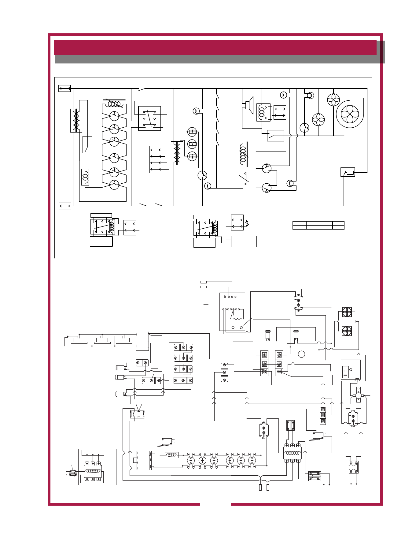
WIRING DIAGRAM
208/240 VOLT AC 60 HZ L2
120 VOLT
N.C.
N.O.
C
PREFILTER
PRESSURE
SWITCH
FIRE
SUPPRESSION
SOLENOID
SOLENOID
ACTUATED
SWITCH
RH REAR
CHANGE
PREFILTER
LIGHT
FILTER PACK
INTERLOCK RT
PRE-FILTER
INTERLOCK RT
BAFFLE FILTER
INTERLOCK RT
PRE-FILTER
INTERLOCK LT
BAFFLE FILTER
INTERLOCK LT
CHECK
FILTERS
LIGHT
DETECTION
END OF
LINE
RELAY
SUPPRESSION
ACTIVATED SWITCH
EQUIPMENT
SHUTOFF
CONTACTOR
L1 T1
L2 T2
L3 T3
EQUIPMENT
CUTOFF
TERMINALS
N.C.
N.O.
C
AIR CURTAIN
SERVICE
REQ',D LIGHT
TIME
DELAY
RELAY
NEUTRAL
N.O.
L1
BUILDING
ALARM
RELAY
WARNING
BUZZER
EQUIPMENT
SHUTOFF
CONTACTOR
AIRFLOW
SHUTDOWN
PRESSURE SWITCH
CURTAIN
FAN 1
CURTAIN
FAN 2
AIR CURTAIN
PRESSURE SWITCH
REPLACE
FILTER
PACK
PRESSURE
SWITCH
CHANGE
FILTER
PACK
LIGHT
SERVICE
REQ'D.
LIGHT
C
NO
NC
C
NO
NC
DETECTION
END OF LINE
RELAY
BLOWER
208/240 VOLT AC 60 HZ L1
208/240 V
APPLIANCE
CONTROL
CIRCUIT
SPST
SWITCHED
POWER
SWITCH L1
SERVICE
DOOR SWITCH
POWER SWITCH L2
LED
LIGHTS
12 VOLT
TB2
TB1
TB3
TB4
TB5
TB6
TB7
TB8
DECK
DECK
CNTR REAR
LH REAR
ELECTRICAL
DETECTORS
DECK
TB3
TB4
208/240V
APPLIANCE
CONTROL
EQUIPMENT
CUTOFF
TERMINALS
CUSTOMER
SUPPLIED
CONTACTOR(S)
TO APPLIANCE
OVER CURRENT
PROTECTED
SUPPLY
EQUIPMENT INTERFACE OPTION 1
SPST
SWITCHED
EQUIPMENT
CUTOFF
TERMINALS
TB5
TB6
CUSTOMER
SUPPLIED
CONTACTOR(S)
CUSTOMER
SUPPLIED
SOURCE CIRCUIT
TO APPLIANCE
OVER CURRENT
PROTECTED
SUPPLY
L3
T3
EQUIPMENT INTERFACE OPTION 2
2M-Z14919 REV A 1-13-2012
VOLTS
208-240 60 HZ 1PH
AMPS
3.5
MODEL
WVU-48
FOR SUPPLY CONNECTION USE #12
AWG COPPER WIRE ONLY SUITABLE
FOR AT LEAST 75C
POWER
SWITCH
VACCUM
SWITCH
(SHUTDOWN)
5
4
2
3
1
BUILDING
ALARM
RELAY
L1 L2 L3
T1
T2 T3
N.C.
N.O.
C
1
4
3
2
CHECK
FILTERS
LIGHT
(AMBER)
REPLACE
FILTERS
LIGHT
(AMBER)
COMMON
NORMALLY
OPEN
NORMALLY
CLOSED
BUZZER
COMMON
NORMALLY
OPEN
NORMALLY
CLOSED
COMMON
L1 L2 L3
T1 T2 T3
POWER TO UNDER-
HOOD APPLIANCES
CUSTOMER
PROVIDED
CONTACTOR
MUST BE
208-240
VAC
TO (T1) AND (T2) OF
FACTORY MOUNTED
CONTACTOR
TERMINAL BLOCK FOR WIRING
CUSTOMERS CONTACTOR/S
(COILED WIRED IN PARALLEL)
W.D. # 2M-Z14919 DATE CODE 0811 REV-
#1
BAFFLE
INTERLOCK
SWITCH
HEPHA INTERLOCK SWITCH
HOOD MOUNTED 10W
LED APPLIANCE
LIGHTS
COMMON
NORMALLY
OPEN
NORMALLY
CLOSED
#1
PRE-FILTER
INTERLOCK
SWITCH
M
SERVICE
REQ
LIGHT
(RED)
COMMON
NORMALLY
OPEN
NORMALLY
CLOSED
#2 BAFFLE
INTERLOCK
SWITCH
COMMON
NORMALLY
OPEN
NORMALLY
CLOSED
#2
PRE-FILTER
INTERLOCK
SWITCH
6
6
7
13
5
4
4
4
4
REPLACE
PRE-FILTER
LIGHT
(AMBER)
COMMON
NORMALLY
OPEN
24
23
COMMON
NORMALLY
OPEN
NORMALLY
CLOSED
LH-DOOR
INTERLOCK
SWITCH
20
NORM
CLOSED
16
14
15
9
4
20
19
18
CUSTOMER SUPPLIED
CONTACTOR CONNECTION
TO
CUSTOMER
SUPPLIED
APPLIANCE
CONTACTOR
1
2
3
8
10
10
11
11
12
16
16
17
15
15
21
21
22
26
15
28
27
27
29
29
30
31
32
22
28
25
BLK
PURPLE
34
4
2
3
1
END OF
LINE
DEVICE
(CURRENT
LIMITING)
RELAY
(SPNO)
N.C.
N.O.
C
COMMON
NORM
CLOSED
SERVICE
REQ
CURTAIN
FAN (RED)
CURTAIN
FAN
MOTORS
AUTOMAN
ELECTRIC
SWITCH
AUTOMAN
ELECTRIC
SWITCH
AIR
CURTAIN
SWITCH
(SHUTDOWN)
47
3
3
33
35
36
44
43
41
42
3940
45
38
TB1
42
46
48
36
36
41
41
L2 INPUTL1 INPUT
50
49
51
53
52
54
PRE-FILTER
P.SWITCH
16
20
59
60
TO CUSTOMER BUILDING
ALARM MONITORING
SYSTEM
TO CUSTOMER SUPPLIED
SWITCHING DEVICE
(SPST)
57
1
2
55
56
58
58
59
60
14
61
62
63
9
5
4
2
3
1
L1
L2
TB1
1 2 3 4 5 6 7
10K Ω
U
V
65
66
67
68
69
70
71
72
73
74
75
75
76
76
65
66
69
68
67
VARIABLE
FREQUENCY
DRIVE
68
67
TB1
TB2
OPEN
NORM
OPEN
NORM
N.O.
3
2
1
(NEUT.)
TIMER
OPEN
COMMON
NORM
CLOSED
NORM
VACCUM SWITCH
(REPLACE FILTER)
COM
12V
208 / 240V
RH CEILING
HEPA
LH CEILING LH LOWER
THERMAL DETECTORS (225°F, N.O.)
RH LOWER
CENTER
YL
BR
AUTOMAN
ACTUATOR
SOLENOID
TB2
FD8-120
#5
#4
#2
#1
#6
#10
#8
TB7
TB8
TB3
TB4
TB6
TB5
TB2
WV48FB-50HZ

M525 p/n 2M-Z17944 OpM WV48FB- Fryer & Broiler Ventless Hood
20
WELLS MANUFACTURING
IL2144
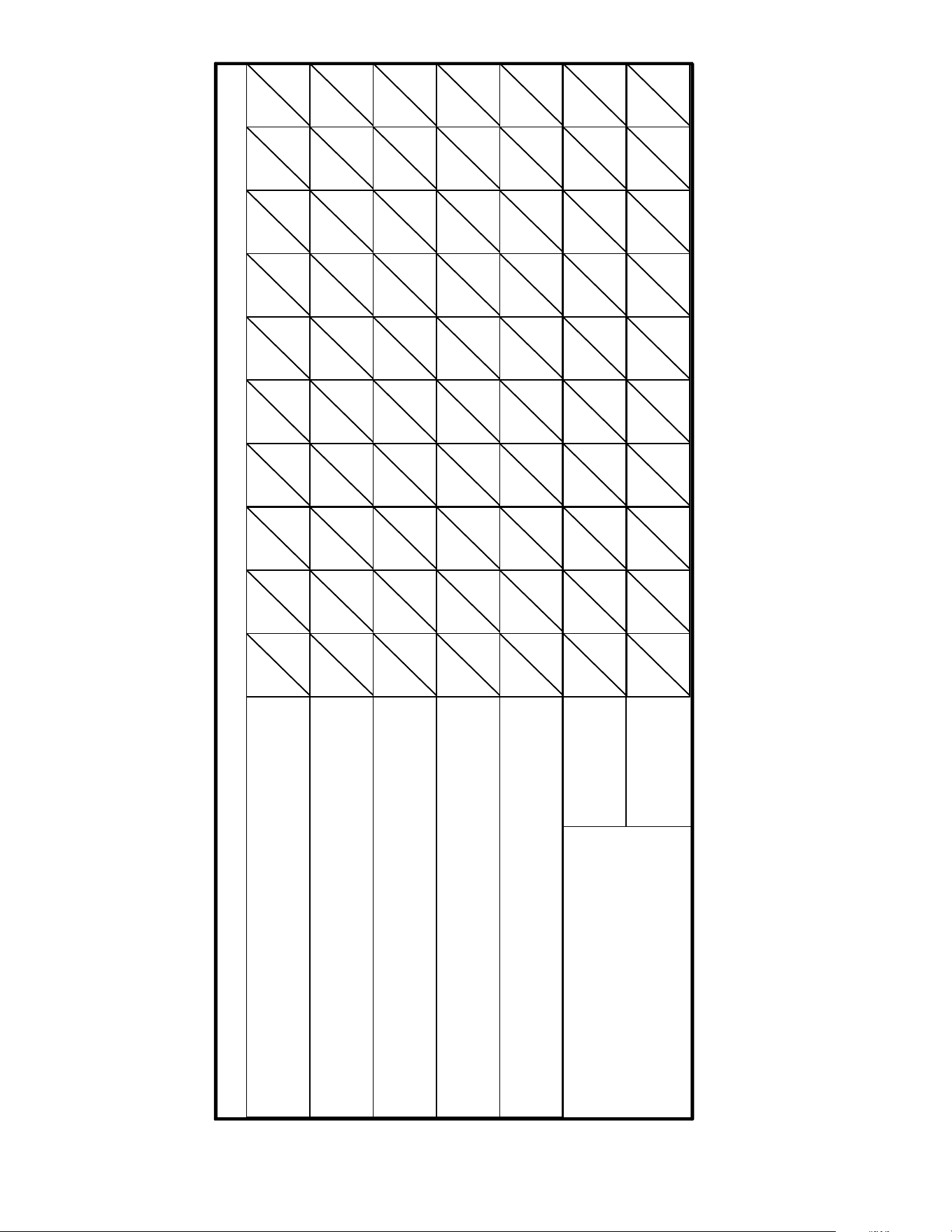
Inspection shall be conducted on a monthly basis in accordance with
the manufacturer’s Operation Manual. At a minimum, this inspection
shall include verification of the following:
OPERATION AGENT DATE
Extinguishing system components:
In proper place and (visually in
good order
Manual pull station actuators for fire
suppression system are obstructed
The maintenance log is in place
and up to date
The nozzle blow-off caps are in place
and in good condition
The hood, duct and protection cooking
appliance have not been replaced,
modified or relocated
Clean plenum GREASE BAFFLE and
BLOWER (max. interval: 3 months)
Change PRE-FILTER and FILTER PACK
(as required)
No obvious physical damage or condition
exists that might prevent operation of the
fire suppression system
VENTILATOR HOOD OWNERS MONTHLY INSPECTION LOG
M525 p/n 2M-Z17944 OpM WV48FB- Fryer & Broiler Ventless Hood
21
Replace fire damper fusible link:
rated @ 212ºF
Max interval: 12 months
IL2378a
This MAINTENANCE LOG is to be performed and completed by a trained technician who has
completed the instruction necessary to perform the maintenance and recharge service.
OPERATION AGENT / DATE
WELLS MANUFACTURING
VENTILATOR HOOD MAINTENANCE LOG
Clean and inspect discharge nozzle in plenum BEFORE filters
MAX. interval: 6 months
Inspect fire suppression detectors, all releasing devices for
actuation, fire suppressant tank liquid level
Max interval: 6 months
(discharge of fire suppressant not a part of this test)
Inspect fire suppression hoses, plumbing and tank for
obstructions and any condition such as, but not limited to,
corrosion and pitting.
Max interval: 6 months
Clean and inspect discharge nozzle in plenum AFTER filters
MAX. interval: 6 months
Inspect and test all filter interlocks
Max. interval: 6 months
Log TEMP
Log mfg DATE
Stamp
THIS MAINTENANCE LOG MUST BE KEPT IN A PROTECTIVE COVER PERMANENTLY ATTACHED TO THE APPLIANCE
Log all repairs and recommendations on reverse side. Any repairs, other than replacement of factory authorized parts, to the fire suppression plumbing system must be
subject to hydrostatic pressure testing.
M525 p/n 2M-Z17944 OpM WV48FB- Fryer & Broiler Ventless Hood
22
29
ANSUL
®
ANSUL INCORPORATED
MARINETTE, WI 54143-2542
MATERIAL SAFETY DATA SHEET
ANSULEX Low pH
QU ICK IDENTIFIE R (In P lant Common Name)
Manufacturer’s
Name:
Emergency
Telephone No.:
ANSUL INCORPORATED
CHEMTREC
(800) 424-9300 or (703) 527-3887
Prepared By:
Address:
One Stanton Street, Marinette, WI 54143-2542
Safety and Health Department
Other Information
Calls:
(715) 735-7411
Date Prepared:
February 1, 1999
SECTION 1 - IDENTITY
SECTION 2 - INGREDIENTS
SECTION 3 - PHYSICAL AND CHEMICAL CHARACTERISTICS (Fire and Explosion Data)
SECTION 4 - PHYSICAL HAZARDS
Common Name (Used on Label):
(Trade Name and Synonyms)
ANSULEX Low pH Liquid Fire Suppressant
CAS No.:
N/A
N/A N/A N/A N/A
N/A
N/A
N/A
N/A
N/A N /A
N/E
N/E
N/E
N/E
N/E
NDA
NDA
NDA
NDA
N/A
Chemical
Name:
N/A T his is a M ixture
Chemical
Fam ily :
M ixture
Formula:
PART A - HAZARDOUS INGREDIENTS
PART B - OTHER INGREDIENTS
Principal Hazardous Component(s) (chemical and common name(s)):
Other Component(s) (chemical and common name(s)):
W t.%
W t.%
CAS No.
CAS No.
ACGIH TLV
ACGIH TLV
Acute Toxicity Data
Acute Toxicity Data
None
Proprietary Mixture of Organic and Inorganic Salts
48.0 - 50.0
Phosphoric Acid 0.2
7664-38-2
Yellow-Green Fluorescent Dye 0.011
518-47-8
Oral LD (rat)
50
6800 mg/kg
EDTA
0.65
64--02-8
Water
Approx. 50.0
7732-18-5
Boiling
Point:
Percent Volatile
by Volume (%):
Solubility
in Water:
Appearance
and Odor:
Flash Point:
Special Fire
Fighting Procedures:
Unusual Fire and
Explosion Hazards:
113ºC
Approx. 50.0
100%
Fluorescent Yellow Colored Liquid, Mild Odor
None to boiling
NONE - THIS IS AN EXTINGUISHING AGENT
None
Vapor Density:
(Air = 1):
Flammable Limits
in Air % by Volume:
1.03
Specific
Gravity (H O=1):
2
Vapor Pressure
(mm Hg):
1.33
Not Determined
Evaporation Rate:
(Butyl Acetate=1):
Approx. 0.005
Reactivity in
Water:
Mild exothermic reaction
Extinguisher
Media:
Auto-Ignition
Temperature:
Stability:
Incompatibility
(Materials to Avoid):
Hazardous
Decomposition Products:
Hazardous
Polymerization:
Unstable
Stable
Conditions
to Avoid:
Conditions
to Avoid:
Reactive Metals, ClF , electrically energized equipment, any material reactive with water.
3
Not established, acrid fumes.
May Occur
W ill N o t O cc ur
M525 p/n 2M-Z17944 OpM WV48FB- Fryer & Broiler Ventless Hood
23
30
SECTION 5 - HEALTH HAZARDS
SECTION 6 - EMERGENCY AND FIRST AID PROCEDURES
SECTION 7 - SPECIAL PROTECTION INFORMATION
SECTION 8 - SPECIAL PRECAUTIONS AND SPILL/LEAK PROCEDURES
HAZARDOUS MATERIAL IDENTIFICATION SYSTEM
ANSULEX Low pH (continued)
Threshold
Limit Value:
None Established
Routes of Entry:
Eye Contact:
Irritant
Irritant
Skin Contact:
Skin Contact:
Inhalation:
Inhalation:
Not an expected route of entry. Can be irritating to m ucous m embranes.
Irritating to mucous membranes. Acute Oral LD (Sprague-Dawley rats) 825.5mg/kg.
50
Ingestion:
Ingestion:
Signs and
Symptom s:
Acute Exposure: Material irritates skin, eyes, and mucous membranes.
Chronic Exposure: None known.
Medical Conditions Generally
Aggravated by Exposure:
None known.
Chemical Listed as
Carcinogen or Potential:
Yes
No
Yes
No
Yes
No
National Toxicology
Program:
I.A.R.C
Monographs:
OSHA
Eye Contact:
Flush and irrigate with water for 15 minutes while holding eyelids open.
If irritation persists, seek medical attention.
Wash thoroughly with soap and water. If irritation persists, seek medical attention.
Fresh air if symptoms occur. If irritation persists, seek medical attention.
Dilute by drinking large quantities of water.
Respiratory Protection
(Specify Type):
N/A
N/A N/A
Ventilation:
Local
Exhaust:
Mechanical
(General):
Protective
Gloves:
Rubber gloves for spill/leak
Eye
Protection:
Chemical goggles recommended during
spill/leak procedures.
Other Protective
Clothing or Equipment:
Eye wash and safety showers are good safety practice.
Precautions to be taken
in Handling and Storage:
Other
Precautions:
Steps to be taken in Case
Material is Released or Spilled:
Waste Disposal
Methods:
Store in original container. Keep tightly closed. Keep separate from acid.
See incompatibility information in Section 4.
Stop leaks. Contain spills. Remove as much as possible. Place in closed container for proper disposal
Wash spill area with large amounts of water to remove traces and neutralize.
Dispose of in compliance with local, state and federal regulations.
HAZARD INDEX
4 SEVERE HAZARD 0 HEALTH
3 SERIOUS HAZARD
2 MODERATE HAZARD 0 FLAMMABILITY
1 SLIGHT HAZARD
0 MINIMAL HAZARD 0 REACTIVITY
N/A = Not Applicable N DA = No D ata Available N/E = Not E stablished
ANSUL and ANSULEX are registered trademarks.
Internet Address: http://www.ansul.com
ANSUL INCORPORATED, ONE STANTON STREET, MARINETTE, WI 54143-2542 Form No. F-90160-6 ©1999 Ansul Incorporated
503 p/n 2M-304989 Owners Manual WVF-886 Ventless Fryer
M525 p/n 2M-Z17944 OpM WV48FB- Fryer & Broiler Ventless Hood
24
TROUBLESHOOTING SUGGESTIONS
NOTE:
FILTERS are the only user serviceable components in this ventilator hood system. For all problems that cannot be remedied by
servicing the lters, contact:
Ventilator section - authorized Wells service agency
Fire suppression system - authorized Ansul® distributor
IMPORTANT:
Contact ANSUL® for re suppression system installation, set-up and service:
Ansul Incorporated 1-800-TO-ANSUL (1-800-862-6785)
One Station Street
Marinette, WI 54143-2542 website http;//www.ansul.com
IMPORTANT:
Parts used in the Ansul® re suppression system are not serviceable by the owner/operator.
Procedures for servicing re suppression equipment are described in:
ANSUL® R-102 SYSTEM DESIGN, INSTALLATION, RECHARGE AND MAINTENANCE MANUAL
(418087, current edition)
NOTE:
ANSUL® Manual 418087 is intended for use by authorized Ansul® service personnel only.
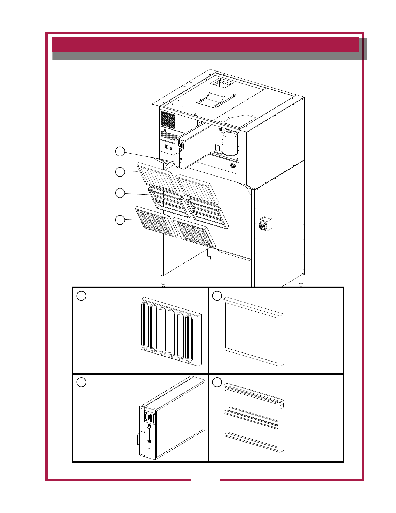
Problem Possible Cause Suggested Remedy
Unit will not operate (no
indicators lights lit)
Disconnected from electric power
Reconnect to electric power
Reset circuit breaker for unit
Unit will not operate
(buzzer sounds)
Fire suppression system not set
Contact an authorized Ansul®
distributor for repairs
CHECK FILTER light lit Filter pack, Pre-lter or bafe lter not in position Properly install lters
REPLACE FILTER light lit
Filter nearing end of service life Arrange to replace lters in a timely manner
Filter pack plugged Replace lter pack
Fire damper in exhaust collar has closed
Contact an authorized Wells service
agent for repairs
SERVICE REQUIRED
light lit (cooking appliance
not operating)
One or more vacuum sensing lines or ports
plugged, or sensing line dislodged.
Contact an authorized Wells service
agent for repairs
NOTE: If, after 20 seconds, there is insufcient airow for proper operation, SERVICE REQUIRED
light will illuminate and under-hood appliance (s) will be de-energized.
Press VENTILATOR POWER SWITCH to OFF, then back to ON to reset system.
M525 p/n 2M-Z17944 OpM WV48FB- Fryer & Broiler Ventless Hood
25
EXPLODED VIEW & PARTS LIST
Filter Maintenance
Model: WVU48 Filter Assy
SK2553 Rev. A , 8/27/2012
Pre-Filter Hood
Part No: 2I-302579
Pre-Filter Cage
Part No: M3-WL0230
Baffle Filter: 16” x 20”
Part No: 2I-Z14670
Filter HEPA/Carbon Pack
Part No: N1-WL0171
1
1
4
2
3
2
3 4
M525 p/n 2M-Z17944 OpM WV48FB- Fryer & Broiler Ventless Hood
26
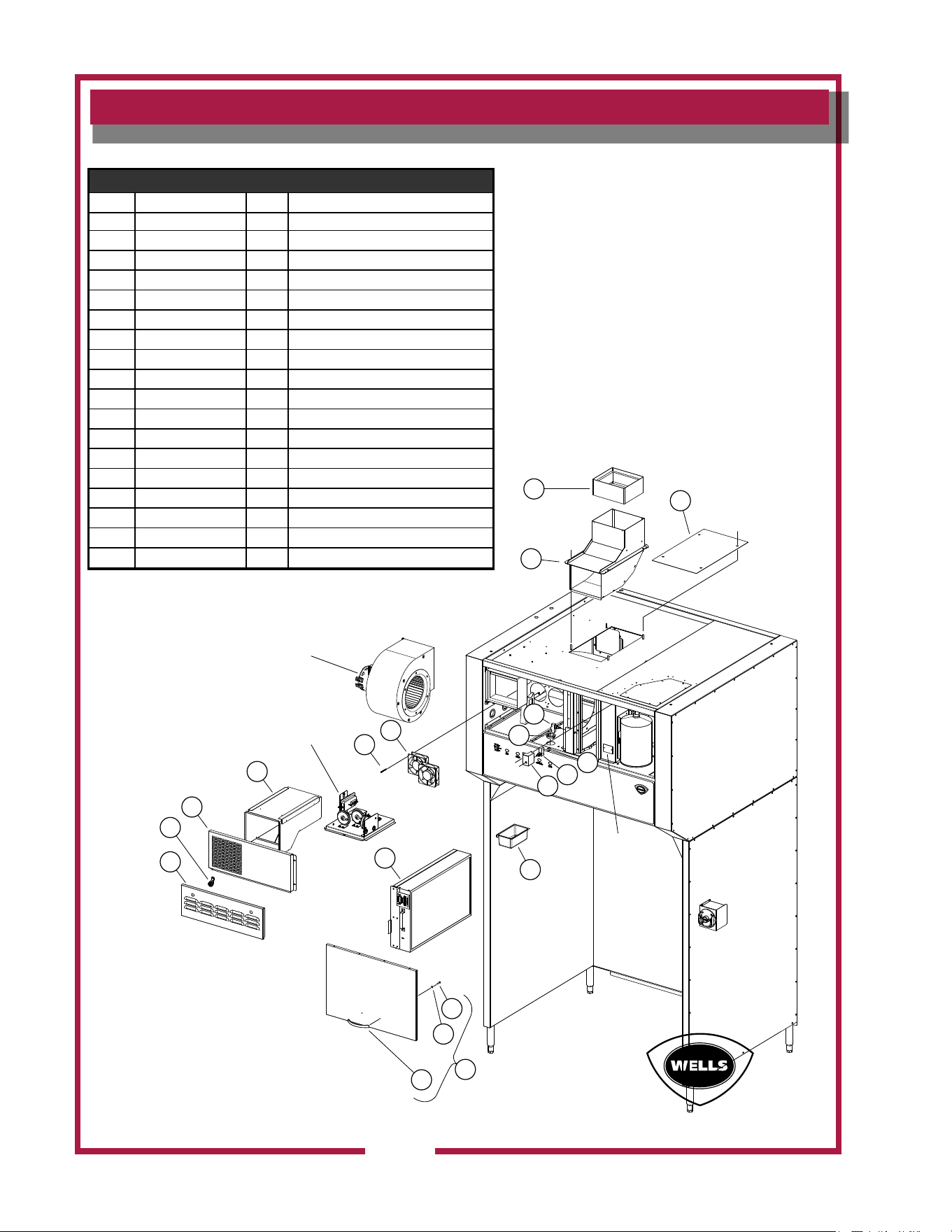
EXPLODED VIEW & PARTS LIST
Universal Hood Internal Control
Model: WVU48 Universal Hood Internal Control
SK2554 Rev. A 2/13/2015
8
9
5
4
10
14
7
4
6
Nameplate
18
19
17
16
See Detail
B
11
12
13
2
3
1
See Detail A
15
Internal Control Assy
Fig No. Part No Qty Description
1 2V-307913 1 DAMPER FIRE 8X9 WVU
2 N1-WL0244 1 TOP DISCHARGE SCOOP ASSY.
3 2E-300407 6 SWITCH MANUAL ADVANCE ROT
4 2K-Y8571 3 BUSHING SNAP 2 1/8
5 2K-Y1139 1 BUSHING HEYCO SB500-6
6 N1-Z14484 1 MOUNTING BRACKET, DOOR
7 2U-200577 2 MOTOR, FAN 240V, HI-OUTPU
8 2C-45201 4 SCREW 8-32X2 PH PAN HD MS
9 N1-WL0172 1 DUCTWORK ASSEMBLY
10 N1-Z14097 1 FRONT DISCHARGE VENTPANEL
11 2R-Z14532 2 CAM LATCH, SLOTTED
12 N1-Z14087 1 ACCESS DOOR, ELECT
13 N1-WL0171 1 FILTER HEPA/CARBON PACK
14 N1-WL0170 1 DOOR ASSY,FRONT ANSUL
15 2R-Z14429 1 HANDLE, 5”
16 2C-1810 2 WASHER 3/16 BURR STL NP
17 Included with #15 2
18 2D-Z14672 1 GREASE CUP
M525 p/n 2M-Z17944 OpM WV48FB- Fryer & Broiler Ventless Hood
27
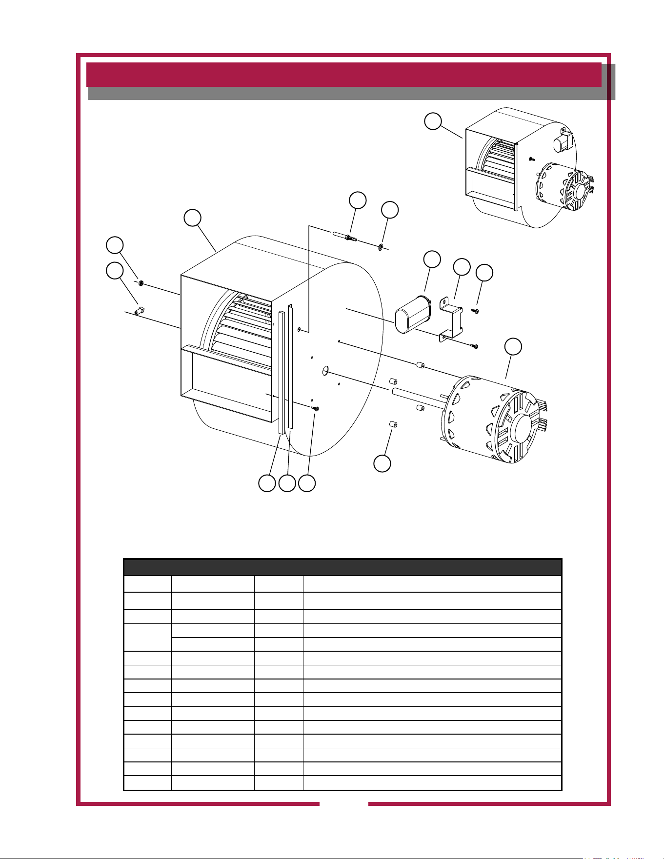
EXPLODED VIEW & PARTS LIST
Universal Hood Internal Control (Detail A)
3
2
4
1
5
6
7
8
9
10
11
91213
Detail A
Blower & Motor Assy
SK2555 Rev. - 1/16/2012
DETAIL A, Blower & Motor Assy
Fig No. Part No WV48FB Description
1 NI-WL0247 1 Blower & Motor Assy
2 Included w/ no 4 1
3
2C-31053 4 NUT #8-32 KEPS NICKEL
2C-1810 4 3/16 WASHER BURR STL NP
4 2U-Z14912 1 BLOWER & WHEEL ASSY
5 2A-Z15331 1 PRESSURE TAP TUBE FITTING
6 2C-Z15332 1 E-CLIP RETAINING RING 1/4”
7 2E-Z14913 1 RUN CAPACITOR, 10MFD, 370V
8 N1-Z15392 1 BRACKET, RUN CAPACITOR
9 2C-301522 4 SCREW 8X12 RPH PAN SELF DRILLING
10 N1-Z14911 1 BLOWER MOTOR MODIFIED
11 2C-Z15394 4 SPACER STAND-OFF, 7/16”
12 N1-Z15316 1 SIDE FLANGE, BLOWER HOUSING
13 N1-Z15317-1 1 GASKET TAPE 10.25 LG, BLOWER SIDE FLANGE
M525 p/n 2M-Z17944 OpM WV48FB- Fryer & Broiler Ventless Hood
28
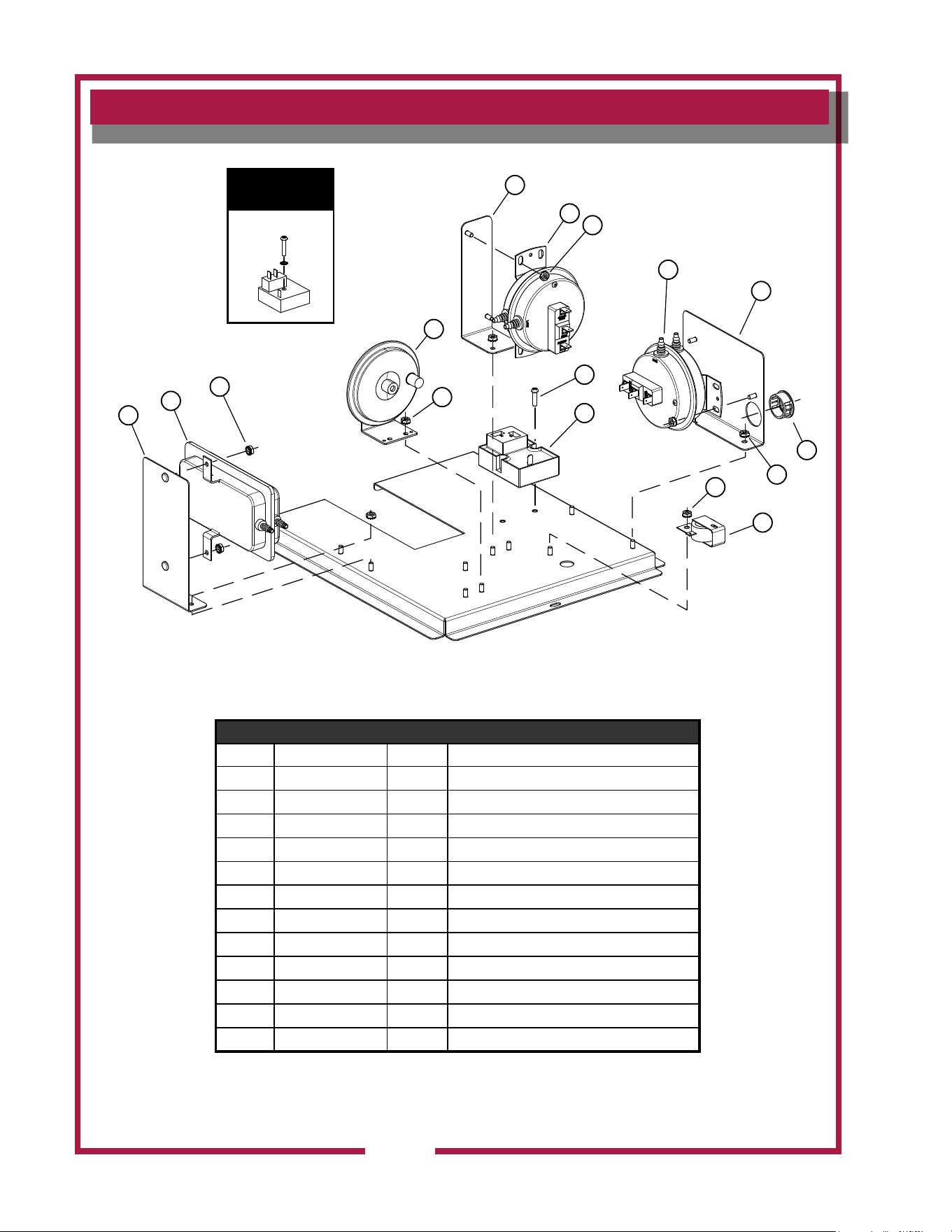
EXPLODED VIEW & PARTS LIST
Universal Hood Internal Control (Detail b)
Detail B
Internal Control Panel Assy
SK2556 Rev. B 5/29/2014
1
2
3
4
5
3
7
9
10
11
3
3
12
8
6
3
Previous Timer
Cube Relay
WS-Z17920
DETAIL B, Internal Control Panel Assy
Fig No Part Number WVU48 Description
1 N1-Z15362 1 BRACKET, PRESSURE SWITCH
2 2E-Z14673 1 PRESSURE SWITCH
3 2C-Z7165 15 NUT 8-32 HEX SS W/EXT WSH
4 2E-302591 1 SWITCH VACUUM #2
5 N1-Z15531 1 BRACKET,HEPA PRESS.SWITCH
6 2E-Z15352 1 VACUUM SWITCH,HEPA FILTER
7 2C-08-07-0042 2 SCREW 8-32X5/8 RHP STL NP
8 2P-Z17415 1 TIMER,CUBE/ RELAY
9 2E-Z15365 1 PRESSURE SWITCH
10 N1-Z14886 1 BRACKET,PRESSURE SWITCH
11 2K-Y5093 2 BUSHING-SNAP #SB-1000-12
12 2J-44834 1 BUZZER 220V ROHS
M525 p/n 2M-Z17944 OpM WV48FB- Fryer & Broiler Ventless Hood
29
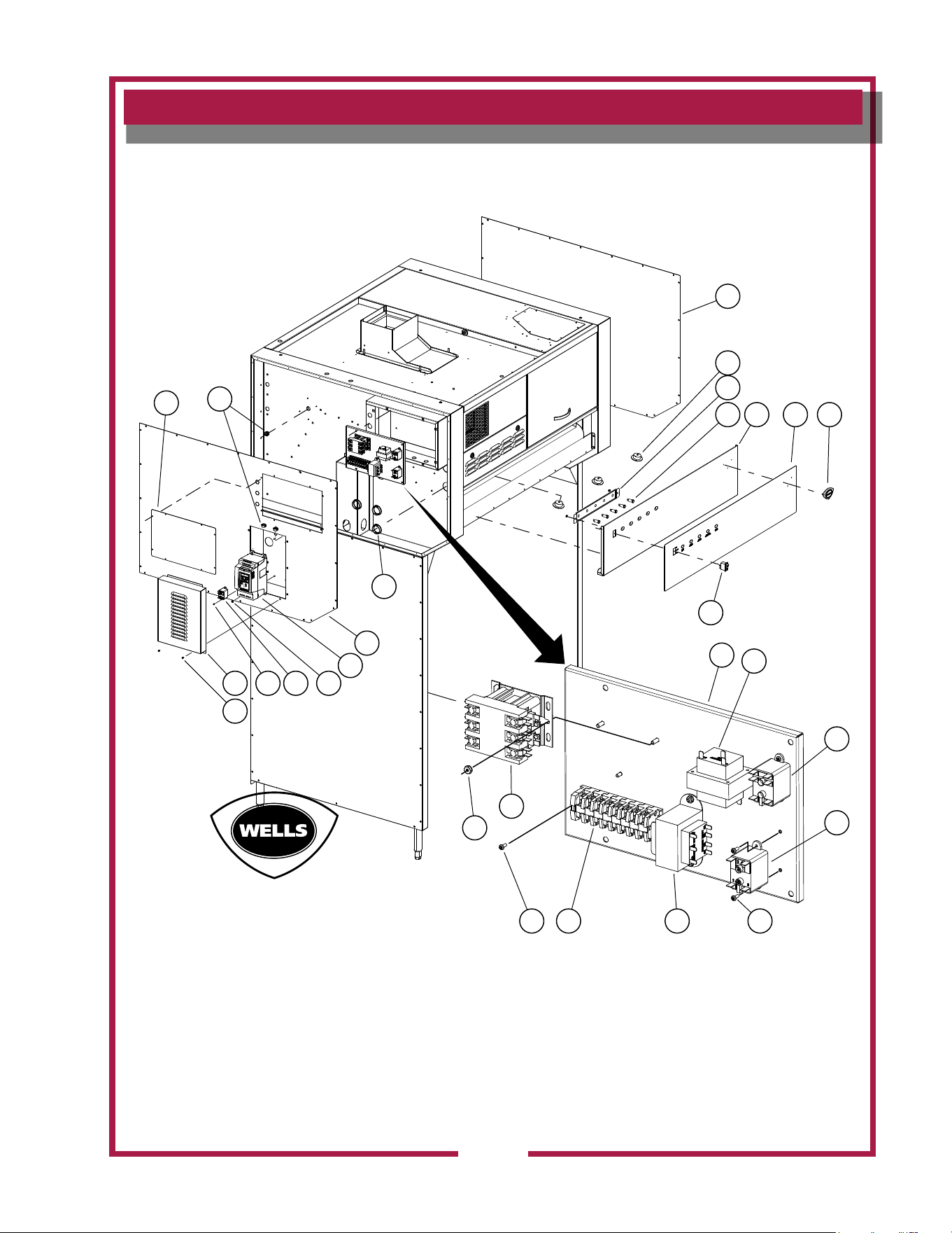
EXPLODED VIEW
Universal Hood Electrical Components
SK2557 Rev. A 5/11/2015
Electrical Components
1
2
4
3
5
8
9
10
11
12
13141513
17
18
21
21
19
22
23112425
26
16
6 7
M525 p/n 2M-Z17944 OpM WV48FB- Fryer & Broiler Ventless Hood
30
Control Panel
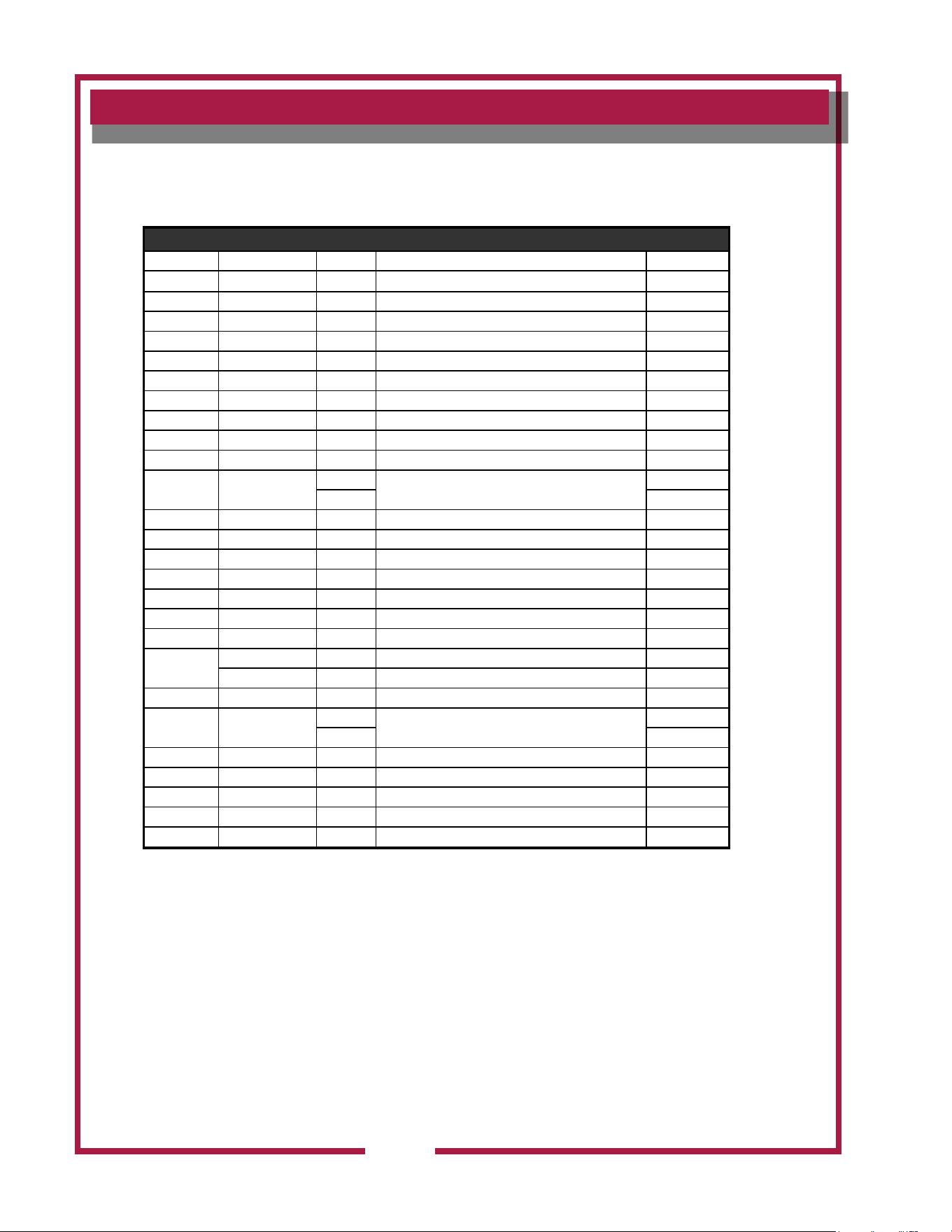
Fig No. Part No Qty Description Application
1 N1-Z14142 1 COVER, HOOD SIDE RIGHT
2 N1-WL0245 3 LED FLOODLIGHT, 45W CW w/TERM
3 N1-Z15418 1 MOUNTING PLATE, CTRL LIGHT
4 N1-WL0281 5 LIGHT SIGNAL, CLEAR LED w/TERM
5 N1-WL0250 1 CONTROL PANEL, FRONT ASSY
6 2M-Z14510 1 GRAPHIC PANEL W/ SWITCH
7 2M-306719 1 LOGO WELLS DIECAST SHIELD
8 2E-305295 1 SWITCH ROCKER 250V 10A GR
9 N1-Z15435 1 ELEC. AUTOMAN BKT. MODIFY
10 2E-Z15018 1 TRANSFORMER, 208/240 12V
11 2E-44514
1
RELAY 208-240V COIL
60Hz
2 50Hz
12 2E-Z15353 1 RELAY, 120V COIL, SPNO
13 2C-1488 6 SCREW 6-32X3/8 RHP STL NP
14 2E-Z15335 1 TRANSFORMER, 208/240
15 WS-WL0282 1 TERMINAL BLOCK ASSY
16 2E-Z14960 1 CONTACTOR, 40A
17 2C-40680 2 NUT 10-32 HEX KEPS MS SS
18 2K-Y8571 3 BUSHING SNAP 2 1/8
19
N1-Z14141 1 COVER, HOOD SIDE LEFT
N1-Z19439 COVER,HOOD SIDE LEFT VFD 50Hz
20 N1-Z15344 1 COVER,SIDE ELECTRIC BOX
21 2K-8043
2
BUSHING SB 5/8” ID
60Hz
5 50Hz
22 2E-Z19467 1 VARIABLE FREQUENCY DRIVE 50Hz
23 2C-Z7165 4 NUT 8-32 HEX SS W/EXT WSH 50Hz
24 2C-1487 2 SCREW 6-32X1/4 RHP STL NP 50Hz
25 N1-Z19440 1 VFD COVER 50Hz
26 2C-6349 8 SCREW #8X3/8 B THP STL NP 50Hz
EXPLODED VIEW & PARTS LIST
Universal Hood Electrical Components
M525 p/n 2M-Z17944 OpM WV48FB- Fryer & Broiler Ventless Hood
31
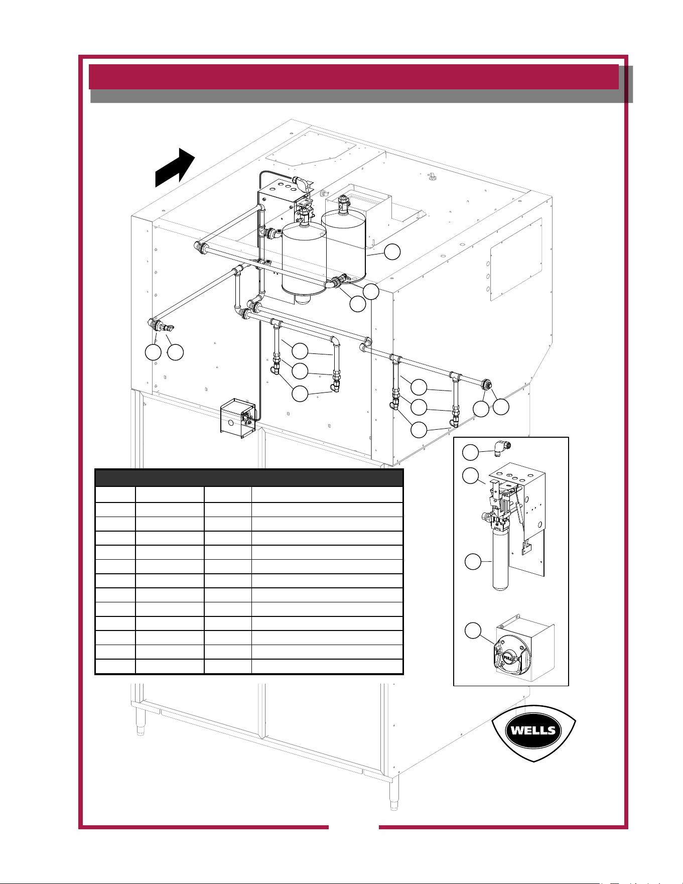
EXPLODED VIEW & PARTS LIST
Universal Hood Suppression System
Suppression System
21
6
1
7
5
1
3
4
3
12
12
4
11
10
9
8
Front
SK2738 Rev. - 1/22/2014
Suppression System
Fig. No Part No WV48FB Description
1 2K-47269 8 ADAPTER 3/8IN QUICK CON A
2 2O-47267 1 NOZZLE ANSUL 1N
3 2O-307481 5 ADAPTER SWIVEL ANSUL
4 2O-Z17942 4 NOZZLE, #230
5 2C-Z15115 1 HEX HEAD PIPE PLUG 3/8NPT
6 2O-302931 1 NOZZLE 1 W
7 2O-304433 2 TANK SS ANSULEX 1.5 GALLO
8 2O-47272 1 PULLEY ELBOW
9 N1-Z15435 1 ELEC. AUTOMAN BKT MODIFY
10 2O-Z14918 1 ANSUL CARTRIDGE LT-30-R
11 2O-308131 1 REMOTE PULL STATION RED
12 2K-Z14561-1 4 PIPE, 3/8” NPT X 6.00” LG,SS
M525 p/n 2M-Z17944 OpM WV48FB- Fryer & Broiler Ventless Hood
32
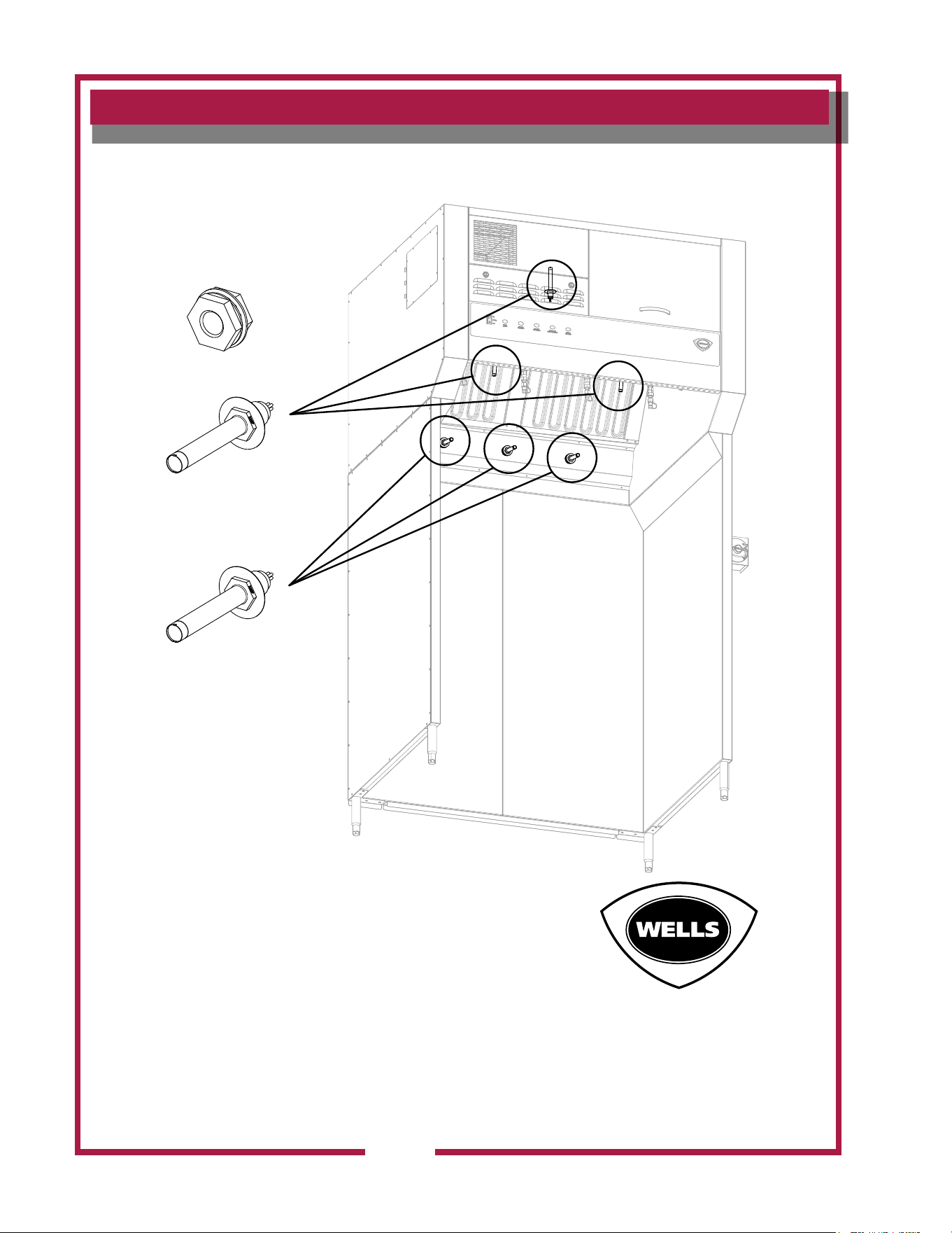
EXPLODED VIEW & PARTS LIST
Universal Hood Detection System
Detection System
Thermal Detector-225°F
Part No: 2T-Z15320
Thermal Detector-275°F
Part No: 2T-Z16137
Adapter 1/2” Quick Seal
Part No: 2T-Z15320
SK2559 Rev. A 7/25/2012
M525 p/n 2M-Z17944 OpM WV48FB- Fryer & Broiler Ventless Hood
33
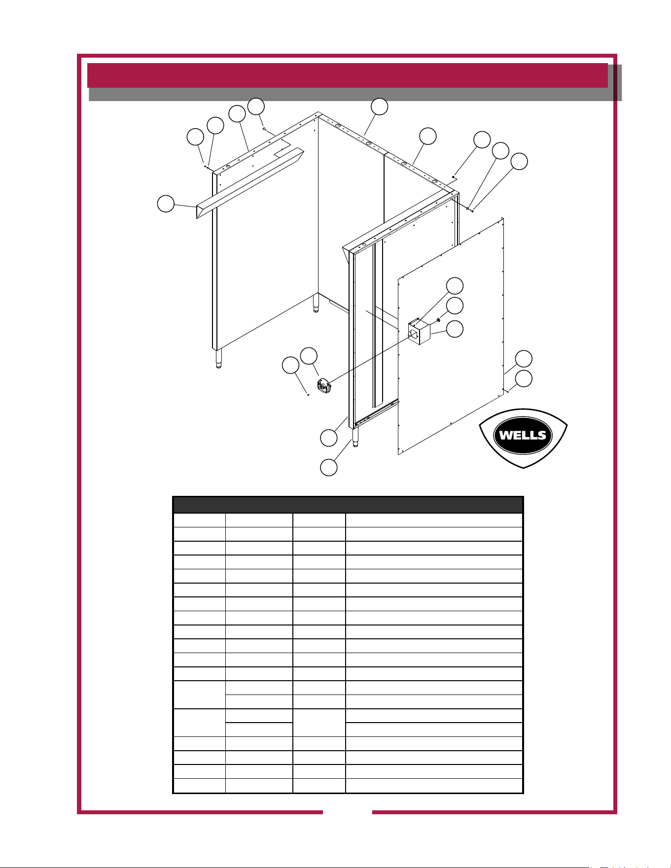
EXPLODED VIEW & PARTS LIST
Universal Hood Base Assy
Model: WVU48 Base Assy
SK2561 Rev. A 11/18/2013
1
2
5
17
5
9
10
12
2
14
13
15
16
11
6
7
8
4
3
Base Assembly
Fig No. Part No WVU48 Description
1 N1-Z15193 2 BASE DEFLECTOR
2 2C-35487 66 SCREW 8-32X5/16 PH TR HD
3 2C-1825 16 WASHER #8 EXT STL NP
4 N1-WL0176 1 BASE,SUPPORT ASSY LFT
5 N1-Z14147 2 BASE,BACK SUPPORT
6 2C-6517 70 NUT 1/4-20 HEX STL NP
7 2C-A27469 70 WASHER,FLAT 1/4IN 7/8OD 1
8 2C-Z5555 70 BOLT 1/4-20 X .75 HEX SS
9 2C-31053 4 NUT 8-32 KEPS MS NICKEL
10 2P-70903-05 1 PLG BTN PLTD MTL 7/8
11 N1-WL0126 1 BOX, MANUAL PULL ASSEMBLY
12
N1-WL0180 1 COVER,BASE SIDE RT ASSY
N1-Z14152 1 COVER, BASE SIDE LEFT
13
2A-307628
4
LEG 6 ADJ 1/2-13 SS
2A-Z16259 LEG, 10” ADJ. 1/2-13 SS (Optional)
14 N1-WL0177 1 BASE,SUPPORT ASSY RT
15 2O-308131 1 REMOTE PULL STATION RED
16 2C-31730 2 SCREW 8-32X1/2 PH TR HD M
17 2C-6349 16 SCREW #8X3/8 B THP STL NP
WELLS MANUFACTURING
265 Hobson Street, Smithville, Tennessee 37166
telephone: 314-678-6314
fax: 314-781-2714
www.wells-mfg.com

