LIAISON
®
XL
cod. I0050
USER MANUAL
en-US – Revision L
(02/2026)

DISCLAIMER
The information contained herein is based on experience and knowledge relating to the subject matter as acquired by
DiaSorin Italia S.p.A.
DiaSorin is not liable for any loss or damage, including consequential or special damages resulting from the use and or
misuse of the contained information be it negligence or other fault.
This document refers to access at the highest level. Working with lower level access may cause a lack of some
functionalities.
LIAISON
®
XL may only be used by authorized and trained personnel.
This document cannot be considered substitutive of official trainings supported by DiaSorin.
In the event of problems or doubts about using the system, contact the local support.
A document that states the list of LIAISON
®
XL Software Versions that are covered by the present User Manual
revision will be provided separately.
The previous legal manufacturer of LIAISON
®
XL was DiaSorin S.p.A.
DiaSorin Italia S.p.A.
Strada per Crescentino snc - 13040 Saluggia (Vercelli) - Italy
www.diasorin.com
DiaSorin Italia S.p.A. 2026. All rights reserved
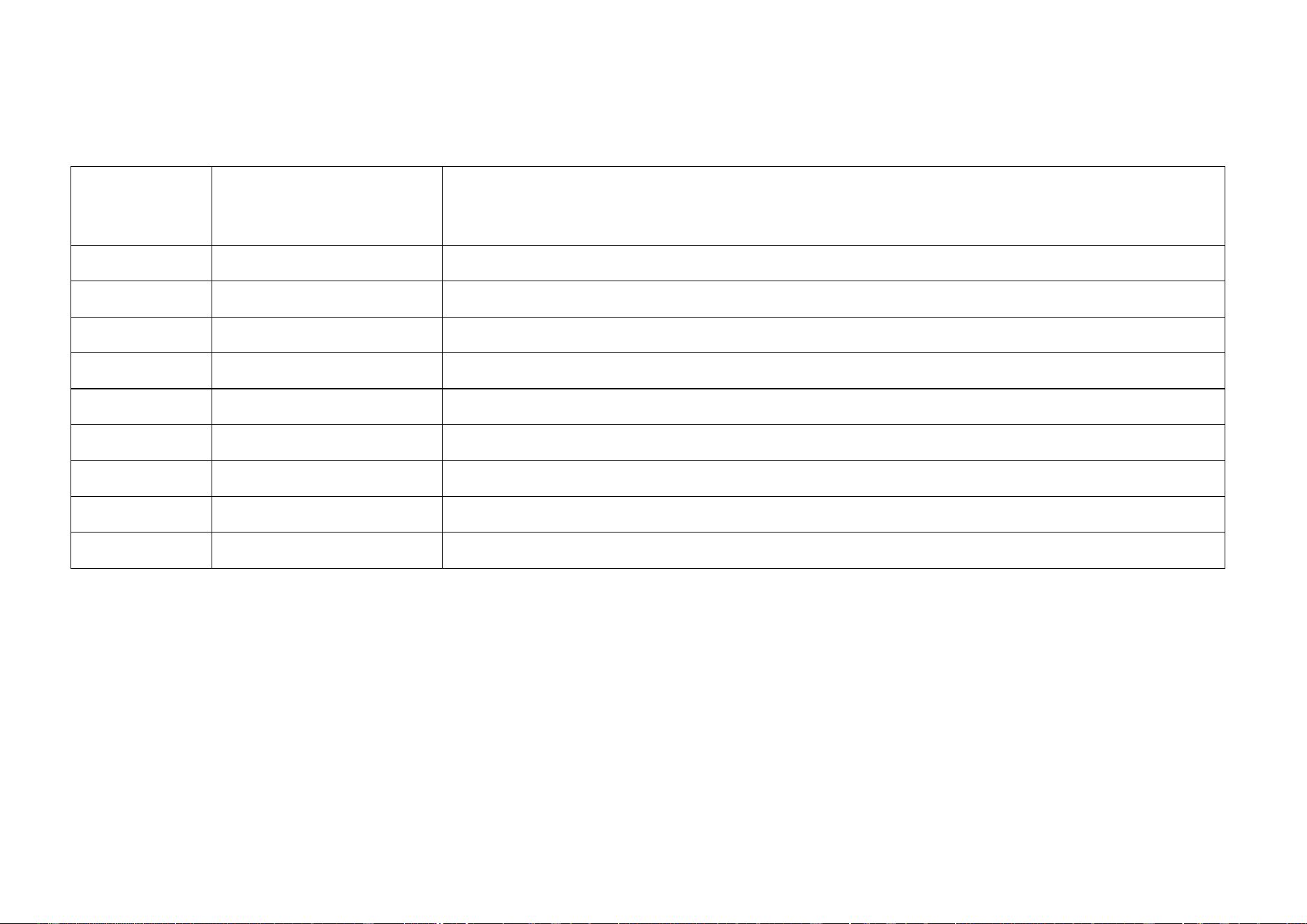
AMENDMENT INDEX
Revision
Impacted
chapter/section
Description of Change(s)
L
All
New Diasorin logo
L
Cover page
New cover page
L
§1.7.2
New Grounding and USB label
L
§1.8.10.3
Added new paragraph “EMC Compliance” related to IEC 60601-1-2
L
§1.8.11
Added new paragraph “Static magnetic field”
L
§1.8.12
Added new paragraph “FCC Radio User Manual Guidance”
L
§1.10.3
New USB label
L
§1.10.5
New Laser label
L
§1.10.6
New Grounding label

Table of Contents
LIAISON XL - Instructions for use TOC - I
Rev. L
Table of Contents
1 Introduction ................................................................................................................................................... 1-1
1.1 Description ................................................................................................................................................................................ 1-1
1.2 Customer Support ..................................................................................................................................................................... 1-2
1.3 Proprietary statement ............................................................................................................................................................... 1-2
1.4 Authorization and disclaimers about Documentation ........................................................................................................... 1-3
1.5 LIAISON
®
XL Warranty .............................................................................................................................................................. 1-4
1.6 DiaSorin Warranty ..................................................................................................................................................................... 1-4
1.7 Messages, Notes and Symbols ................................................................................................................................................ 1-5
1.8 Hazard Instructions ................................................................................................................................................................. 1-12
1.9 Safety residual risks for User ................................................................................................................................................. 1-26
1.10 Instrument Labelling and Safety Labels ............................................................................................................................... 1-36
1.11 Operational Precautions and limitations............................................................................................................................... 1-63
1.12 Installation of the System ....................................................................................................................................................... 1-66
1.13 Removal of the System ........................................................................................................................................................... 1-67
Table of Contents
TOC - II LIAISON XL - Instructions for use
Rev. L
2 PC security measures ................................................................................................................................... 2-1
2.1 Introduction ............................................................................................................................................................................... 2-1
2.2 Unauthorized Local Access ..................................................................................................................................................... 2-1
2.3 Malware ...................................................................................................................................................................................... 2-3
2.4 Unauthorized access via network ............................................................................................................................................ 2-4
2.5 System update ........................................................................................................................................................................... 2-5
2.6 Local/network printing .............................................................................................................................................................. 2-5
2.7 Remote access .......................................................................................................................................................................... 2-6
2.8 Privacy ....................................................................................................................................................................................... 2-7
2.9 Security Requirements for Operating Environment ............................................................................................................... 2-9
3 Measuring Principle of the LIAISON
®
XL Immunoassays ......................................................................... 3-1
3.1 Explanations for Steps of Assays ........................................................................................................................................... 3-1
3.2 Measuring Principle .................................................................................................................................................................. 3-5
3.3 Measuring Function Description ............................................................................................................................................. 3-6
3.4 Calibration (quantitative) .......................................................................................................................................................... 3-7
3.5 Calibration (qualitative) ............................................................................................................................................................ 3-9
Table of Contents
LIAISON XL - Instructions for use TOC - III
Rev. L
4 System Description ....................................................................................................................................... 4-1
4.1 Overview .................................................................................................................................................................................... 4-1
4.2 Use of the Modules ................................................................................................................................................................. 4-15
4.3 Accessories and Consumables ............................................................................................................................................. 4-48
5 Use of the System ......................................................................................................................................... 5-1
5.1 Safety and Hints ........................................................................................................................................................................ 5-1
5.2 Typographical Conventions ..................................................................................................................................................... 5-2
5.3 Daily activities plan ................................................................................................................................................................... 5-5
5.4 Start-up ...................................................................................................................................................................................... 5-6
5.5 Check Cuvettes, Disposable Tips, Starter Reagents and Liquid Containers ....................................................................... 5-9
5.6 Load Patient Samples or Controls and Assign Assays ....................................................................................................... 5-51
5.7 Integrals, Calibrators, Ancillary reagents ............................................................................................................................. 5-68
5.8 Start Worklist ........................................................................................................................................................................... 5-81
5.9 Results ..................................................................................................................................................................................... 5-82
5.10 Routine errors ......................................................................................................................................................................... 5-96
5.11 Unloading................................................................................................................................................................................. 5-97
5.12 Shut Down/End of Day Maintenance ................................................................................................................................... 5-104
Table of Contents
TOC - IV LIAISON XL - Instructions for use
Rev. L
6 Software Functions ....................................................................................................................................... 6-1
6.1 General ....................................................................................................................................................................................... 6-1
6.2 Header ...................................................................................................................................................................................... 6-18
6.3 Main Category Loading .......................................................................................................................................................... 6-22
6.4 Main Category Results ........................................................................................................................................................... 6-43
6.5 Main Category Events ............................................................................................................................................................. 6-86
6.6 Main Category Definitions ...................................................................................................................................................... 6-93
6.7 Main Category System .......................................................................................................................................................... 6-122
6.8 Main Category Diagnostics .................................................................................................................................................. 6-157
6.9 Main Category Maintenance ................................................................................................................................................. 6-160
6.10 Main Category Status ........................................................................................................................................................... 6-167
6.11 External Backup Viewer ....................................................................................................................................................... 6-179
7 Quality Control (QC) ..................................................................................................................................... 7-1
7.1 Overview .................................................................................................................................................................................... 7-1
7.2 Starting the Software ................................................................................................................................................................ 7-2
7.3 Loading ...................................................................................................................................................................................... 7-7
7.4 Results ..................................................................................................................................................................................... 7-16
7.5 Settings .................................................................................................................................................................................... 7-46
Table of Contents
LIAISON XL - Instructions for use TOC - V
Rev. L
7.6 Maintenance ............................................................................................................................................................................ 7-62
7.7 Audit ......................................................................................................................................................................................... 7-76
7.8 Administration ......................................................................................................................................................................... 7-78
7.9 Help .......................................................................................................................................................................................... 7-83
7.10 Error Messages ....................................................................................................................................................................... 7-85
8 Maintenance .................................................................................................................................................. 8-1
8.1 Safety and Hints ........................................................................................................................................................................ 8-1
8.2 Scheduled Maintenance Tasks ................................................................................................................................................ 8-5
8.3 Light Check ................................................................................................................................................................................ 8-5
8.4 Preparation of Liqui-Nox
®
solution .......................................................................................................................................... 8-6
8.5 Load and Unload the Cleaning Solution Bottle ...................................................................................................................... 8-7
8.6 Clean the pipettor probes ....................................................................................................................................................... 8-11
8.7 Clean the analyzer interior ..................................................................................................................................................... 8-12
8.8 Clean the primary and the intermediate tanks ...................................................................................................................... 8-13
8.9 Clean the covers ..................................................................................................................................................................... 8-26
8.10 Cuvette removal ...................................................................................................................................................................... 8-27
8.11 Automated actions performed by the system ...................................................................................................................... 8-28

Table of Contents
TOC - VI LIAISON XL - Instructions for use
Rev. L
9 Troubleshooting and Error Messages ........................................................................................................ 9-1
9.1 Error Messages and Information Messages ........................................................................................................................... 9-1
10 Technical Data ............................................................................................................................................. 10-1
10.1 Power Requirements .............................................................................................................................................................. 10-1
10.2 Laser of the Bar-code Scanner .............................................................................................................................................. 10-2
10.3 Computer and Connections ................................................................................................................................................... 10-5
10.4 Dimensions .............................................................................................................................................................................. 10-6
10.5 System Clearance ................................................................................................................................................................... 10-7
10.6 Weight ...................................................................................................................................................................................... 10-8
10.7 Environmental Conditions ...................................................................................................................................................... 10-9
10.8 Noise ........................................................................................................................................................................................ 10-9
10.9 Temperature Range .............................................................................................................................................................. 10-10
10.10 Water quality .......................................................................................................................................................................... 10-10
10.11 Optional direct plumbing connection specification ........................................................................................................... 10-11
Table of Contents
LIAISON XL - Instructions for use TOC - VII
Rev. L
11 Appendix A: Disinfection procedure ......................................................................................................... 11-1
11.1 Introduction ............................................................................................................................................................................. 11-1
11.2 Hazards .................................................................................................................................................................................... 11-2
11.3 Preparation of Liqui-Nox
®
solution ........................................................................................................................................ 11-5
11.4 Alcoholic solution specifications .......................................................................................................................................... 11-5
11.5 Preparation of sodium hypochlorite solution ....................................................................................................................... 11-5
11.6 Disinfection procedure – Front and System Modules ......................................................................................................... 11-6
11.7 Disinfection procedure – Cabinet .......................................................................................................................................... 11-8
12 Appendix B: Optional direct plumbing connection for DI water ............................................................. 12-1
12.1 Introduction ............................................................................................................................................................................. 12-1
12.2 Direct plumbing components ................................................................................................................................................. 12-2
12.3 Direct plumbing functionalities .............................................................................................................................................. 12-4
12.4 Clean the primary and the intermediate tanks ...................................................................................................................... 12-5
12.5 Error condition and error handling on direct plumbing..................................................................................................... 12-21
Table of Contents
TOC - VIII LIAISON XL - Instructions for use
Rev. L
1 Introduction
LIAISON XL - Instructions for use Page 1-1
Rev. L
1 Introduction
This manual was created to assist the laboratory user with the utilization of the LIAISON
®
XL and LIAISON
®
XL with Workcell Upgrade Kit
cchemiluminescence analyser (see chapter 1.1.1). This manual includes specific definitions as well as handling and maintenance of the
instrument.
1.1 Description
The LIAISON
®
XL is a fully automated chemiluminescence analyzer, performing the complete sample processing (sample pre-dilutions,
sample and reagent dispensing, incubations, wash processes) as well as the measurement and evaluation. The instrument is controlled via
the PC LIAISON
®
XL software. This software, which was specifically designed for this purpose, allows the user to process the pre-defined
assays. The clear structure with intuitive user-guidance allows simple and quick operation of daily routine jobs.
LIAISON
®
XL Workcell Upgrade Kit: Components for the LIAISON
®
XL Analyzer that allow the analyzer to be connected to a third party
Laboratory Automation System (LAS) having compatible connection capability for the performance of pre- and post-analytical sample handling
processes. The LIAISON
®
XL Workcell Upgrade Kit also maintains the LIAISON
®
XL Analyzer’s performance as a stand-alone instrument.
1.1.1 Intended Use
The LIAISON
®
XL Analyzer is an automated discrete continuous loading chemiluminescent immunoassay (CLIA) analyzer for in
vitro diagnostic analysis of CLIAs on human specimens cleared for use on the analyzer.
It is only to be used with FDA cleared chemiluminescent immunoassays that are marketed by DiaSorin for the LIAISON
®
XL Analyzer.
The analyzer can be connected to a third party Laboratory Automation System (LAS) which has been previously cleared for use with FDA
cleared assays.
All the references to LIAISON
®
XL in this manual are also applicable to the LIAISON
®
XL with Workcell Upgrade Kit.
Specific references to LIAISON
®
XL with Workcell Upgrade Kit are explicitly indicated.
1 Introduction
Page 1-2 LIAISON XL - Instructions for use
Rev. L
Please check with DiaSorin Italia S.p.A. for the compatibility between a lab automation system and LIAISON
®
XL
with Workcell Upgrade Kit.
1.2 Customer Support
If you have any questions about the LIAISON
®
XL Diagnostic System, please contact your local DiaSorin Customer Support Representative to
get answers to your inquiries.
1.3 Proprietary statement
The LIAISON
®
XL System software programs and system documentation are protected by copyright laws. All rights are reserved.
The software and manual were developed solely for use with the LIAISON
®
XL System and for in vitro diagnostic applications as specified in
the operating instructions.
The information, documents and related graphics published herein (the "Documentation" or “Document”) are the sole property of
DiaSorin Italia S.p.A. Permission to use the Information is granted, provided that:
• use of the Documentation is for operating DiaSorin products by DiaSorin trained personnel or informational use only;
• the copyright notice appears on all copies;
• the Documentation is not modified in any way; and
• no graphics are used separately from accompanying text.
Each person assumes full responsibility and all risks arising from use of the Documentation. The Documentation may include technical
inaccuracies or typographical errors. DiaSorin Italia S.p.A. reserves the right to make additions, deletions, or modifications to the
Documentation at any time without any prior notification.
1 Introduction
LIAISON XL - Instructions for use Page 1-3
Rev. L
1.4 Authorization and disclaimers about Documentation
The information contained herein is based on experience and knowledge relating to the subject matter as acquired by DiaSorin Italia S.p.A.
This Document refers to access at the highest level. Working with lower level access may cause a lack of some functionality.
The user manual and the LIAISON
®
XL Chemiluminescence analyzer are to be used by authorized personnel only. Operate the Instrument
following the indications and procedures described in the operating instructions for the LIAISON
®
XL Analyzer.
Follow all warnings, cautions, and notes indicated on the LIAISON
®
XL Analyzer and in the operating instructions. Failure to do this may result
in human injuries or damage to instrument.
No part of this document may be reproduced, stored, retrieved, or transmitted in any form or by any means without the prior written permission
of DiaSorin Italia S.p.A.
All samples, if any (printouts, graphics, displays, screens, etc.), are for information and illustration purposes only and shall not be used for
clinical or maintenance evaluations. Data shown in sample printouts and screens do not reflect actual patient names or test results.
The Documentation was developed to be used by DiaSorin Italia S.p.A. trained personnel, by other persons knowledgeable or experienced
with the operation and service of the product identified, or under the direct supervision and with cooperation from DiaSorin Italia S.p.A.
technical sales or service representatives.
This Document cannot be considered substitutive of official trainings supported by DiaSorin.
In no event shall DiaSorin Italia S.p.A. or its affiliates be liable for any damages or losses incurred in connection with or arising from the use of
the Documentation by persons not fully trained by DiaSorin Italia S.p.A. This limitation shall not apply to those persons knowledgeable or
experienced with the operation and service of the product identified, or under the direct supervision and with cooperation from DiaSorin Italia
S.p.A. technical sales or service representatives.
In the event that any user of the Information should make any questions, comments, suggestions, ideas or any other kind of oral, written or
electronic feedback to DiaSorin, any information submitted therewith shall be considered non-confidential, and DiaSorin shall be free to
reproduce, edit, publish or otherwise use such information for any purposes whatsoever including, without limitation, the research,
development, manufacture, service, use, or sale of products incorporating such information and no liability will be borne by DiaSorin in
connection with its content, including its truthfulness and accuracy and its non-infringement of any other person's proprietary rights.
Updates to the Documentation may be provided in either paper or electronic format. Always refer to the latest documents for the most current
information.
In the event of problems or doubts about using the system, contact your local support representative.
1 Introduction
Page 1-4 LIAISON XL - Instructions for use
Rev. L
1.5 LIAISON
®
XL Warranty
DiaSorin warrants instruments sold by DiaSorin or any of its related company to be free from defects in workmanship and materials during
normal use by the original purchaser. Unless otherwise expressly agreed to in writing by DiaSorin, this warranty shall continue for a period of
one year, commencing twenty-one (21) days from the date of shipment to the original purchaser, or until title is transferred from the original
purchaser, whichever occurs first (the "Warranty Period").
If any defects occur during the Warranty Period, contact your DiaSorin Italia S.p.A. Service Representative immediately, and be prepared to
furnish information including the serial number, the model number, and pertinent details concerning the defect.
This Warranty does not cover defects or malfunctions which: (1) are not reported to DiaSorin Italia S.p.A. during the Warranty Period and
within one week of occurrence; (2) result from chemical decomposition or corrosion; (3) are caused primarily by failure to comply with any
requirements or instruction contained in the applicable DiaSorin Italia S.p.A. User Manual; or (4) result from maintenance, repair, or
modification, performed without DiaSorin's authorization, (5) related to normal wear and tear.
DiaSorin Italia S.p.A.’s liability for all matters arising from the supply, installation, use, repair, and maintenance of the instrument, whether
arising under this Warranty or otherwise, shall be limited solely to the repair or (at DiaSorin Italia S.p.A’s sole discretion) replacement of the
instrument or of components thereof. Replaced parts shall become the property of DiaSorin Italia S.p.A. In no event shall DiaSorin be liable for
injuries sustained by third parties, consequential damages, and/or lost profits.
The warranty does not cover the software included in the system, which is subject to the warranty stated in the Software License Agreement.
The warranty is country dependent, based on local legal requirements.
The foregoing is the sole warranty made by DiaSorin Italia S.p.A. regarding the instrument, and DiaSorin specifically disclaims all other
warranties, expressed or implied, including the warranties of merchantability and fitness implied for a particular purpose.
1.6 DiaSorin Warranty
DiaSorin Italia S.p.A. makes no representations or warranties of any kind or nature with respect to the documentation. DiaSorin Italia S.p.A.
hereby disclaims all representations and warranties, whether express or implied, created by law, contract or otherwise, including, without
limitation, any warranties of merchantability, fitness for a particular purpose, title or non-infringement. In no event shall DiaSorin Italia S.p.A. be
liable for any damages of any kind or nature, including, without limitation, direct, indirect, special (including loss of profit) consequential or
incidental damages arising from or in connection with the existence or use of the information, regardless of whether DiaSorin Italia S.p.A. has
been advised as to the possibility of such damages.
1 Introduction
LIAISON XL - Instructions for use Page 1-5
Rev. L
1.7 Messages, Notes and Symbols
The symbols described hereafter are used in the current manual, on the instrument and on its packaging.
1.7.1 Display of Warnings and Notes
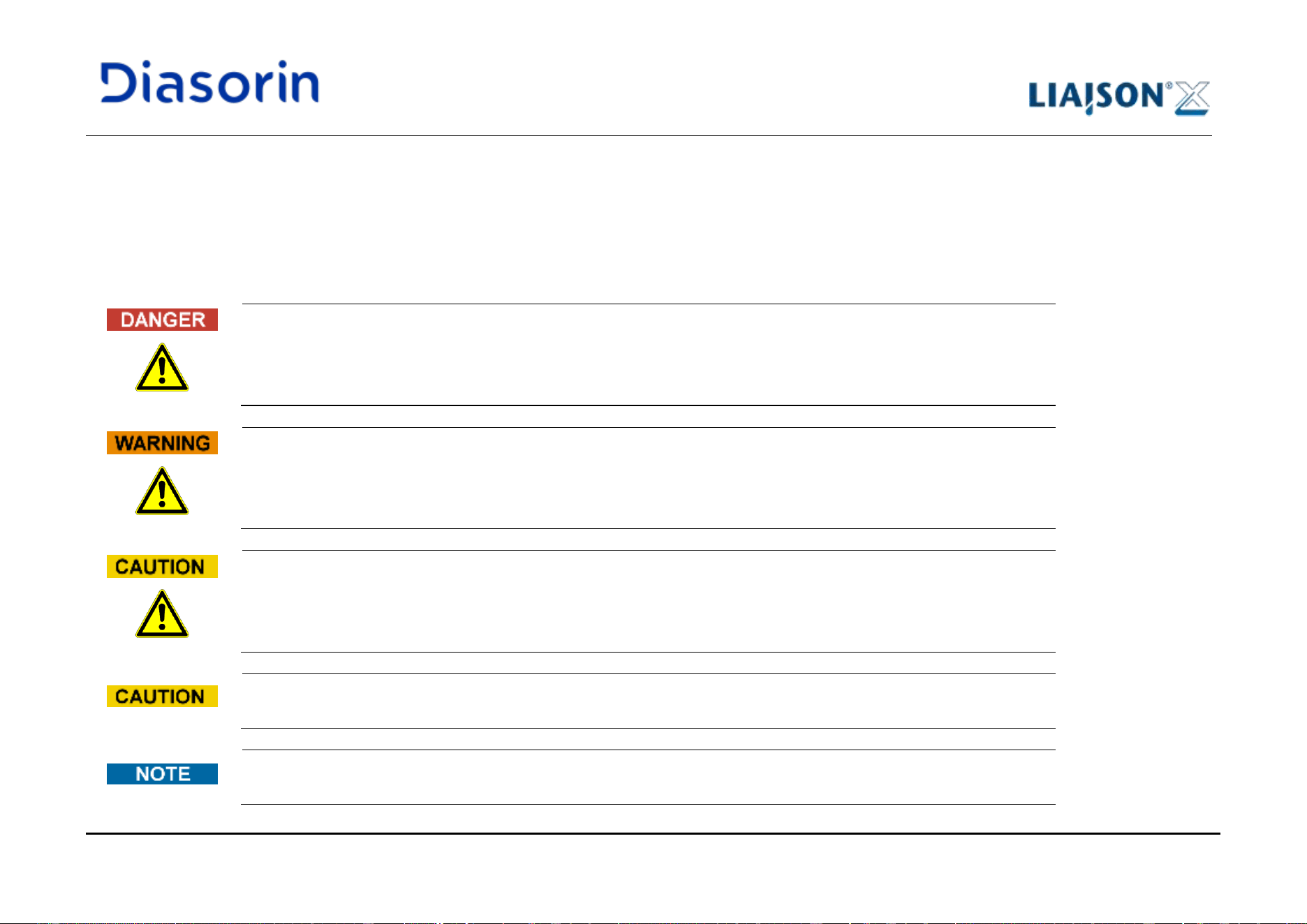
The signal word "Danger" and the relating pictograph describe immediate dangers.
The non-observance of a danger warning is immediate and will result in death or at least serious irreversible injury.
Damage to the system or an adverse effect on the system function cannot be excluded.
The signal word "Warning" and the relating symbol describe potential dangers.
The non-observance of a warning is potential and can result in death or at least serious irreversible injury. Damage to
the system or an adverse effect on the system function cannot be excluded.
The signal word "Caution" and the relating symbol describe potential dangers/problems.
The non-observance of safety instructions can result in minor injuries. Damage to the system or an adverse effect on
the system function cannot be excluded.
The signal word “Caution” describes potential problems. The non-observance of a caution instruction can result in
damage to the system or an adverse effect on the system functionality.
The signal word "Note" describes potential problems. The non-observance of notes can result in an adverse effect
on the system function.
1 Introduction
Page 1-6 LIAISON XL - Instructions for use
Rev. L
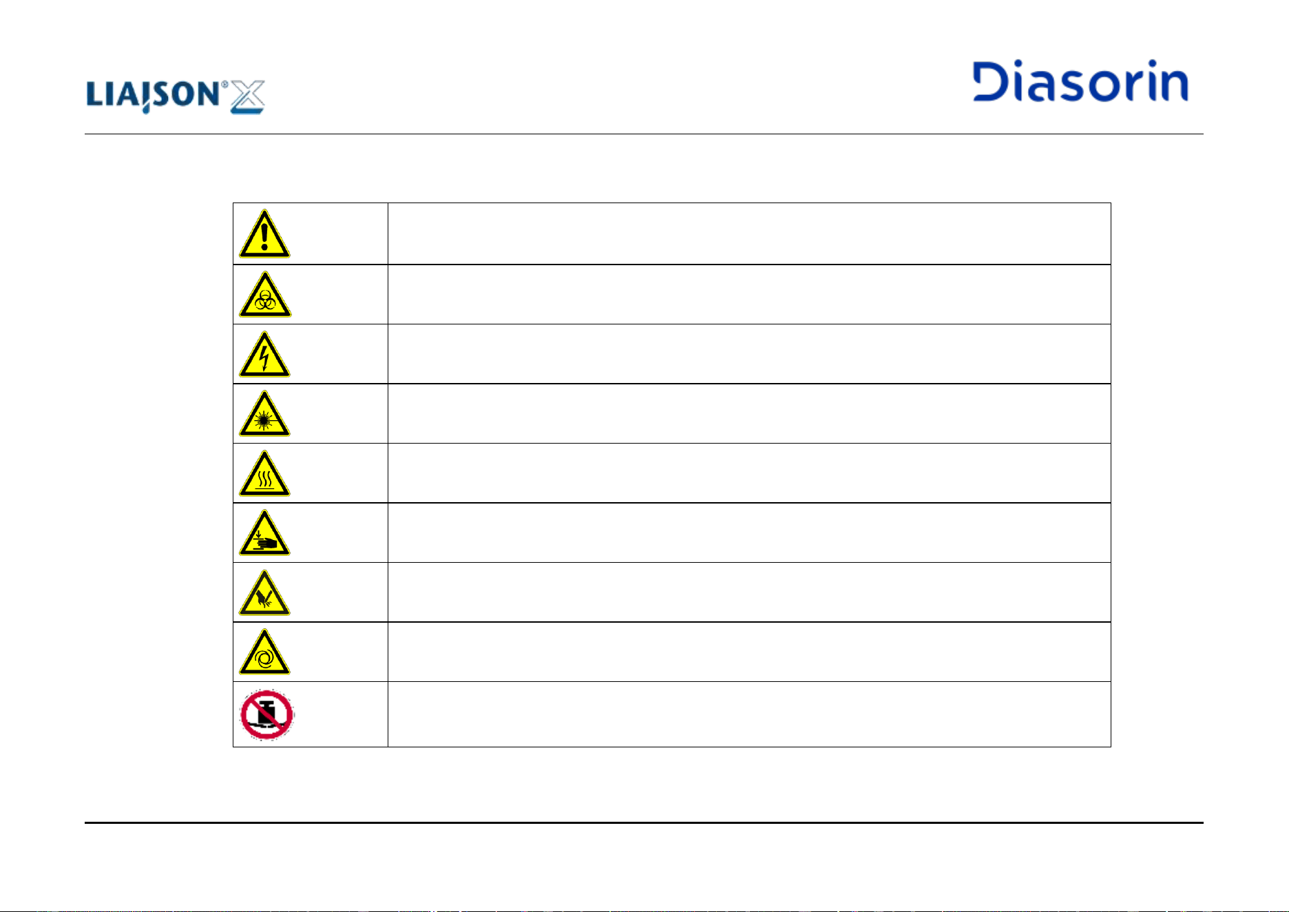
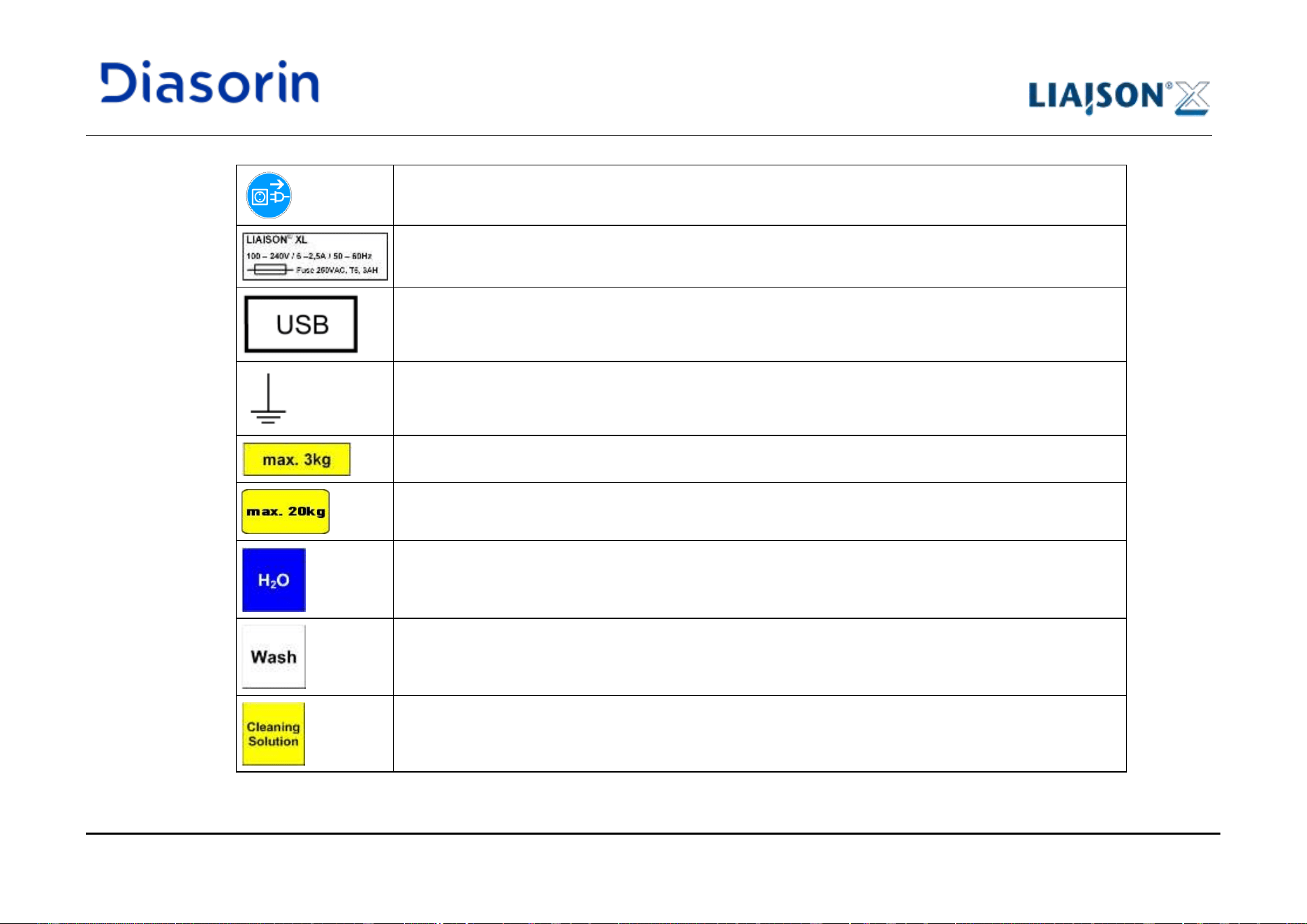
1.7.2 Utilized Warning Symbols
Caution, risk of danger to person or damage to equipment! Consult instructions for use!
Biohazard!
Electrical hazard!
Laser hazard!
Caution, hot surface!
Mechanical hazard!
Cut injury hazard!
Automatic start-up!
No objects shall be put on the opening flaps.
1 Introduction
LIAISON XL - Instructions for use Page 1-7
Rev. L
Disconnect mains power connector before servicing!
Power Supply characteristics
USB label
Grounding label
Maximum supported load for extensible board.
Maximum load for printer support.
Water Tank
Wash Solution Tank
Cleaning Solution Tank
1 Introduction
Page 1-8 LIAISON XL - Instructions for use
Rev. L
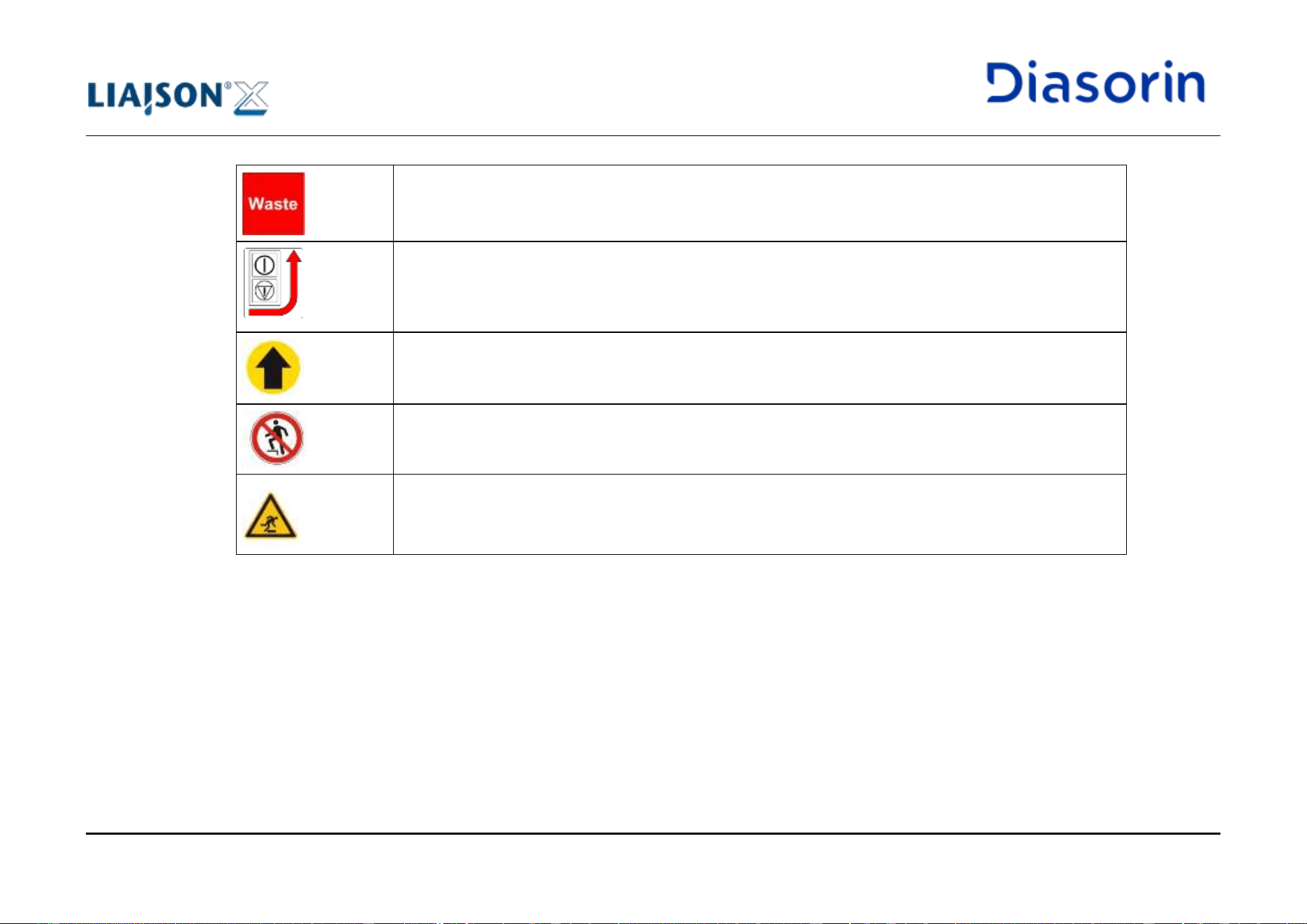
Liquid Waste Tank
Indication of the location of Main Switch / Emergency Stop button.
Close the drawer*
* available on instruments with cabinet drawers
Don’t step*
* available on instruments with cabinet drawers
Stumble hazard*
* available on instruments with cabinet drawers
1 Introduction
LIAISON XL - Instructions for use Page 1-9
Rev. L
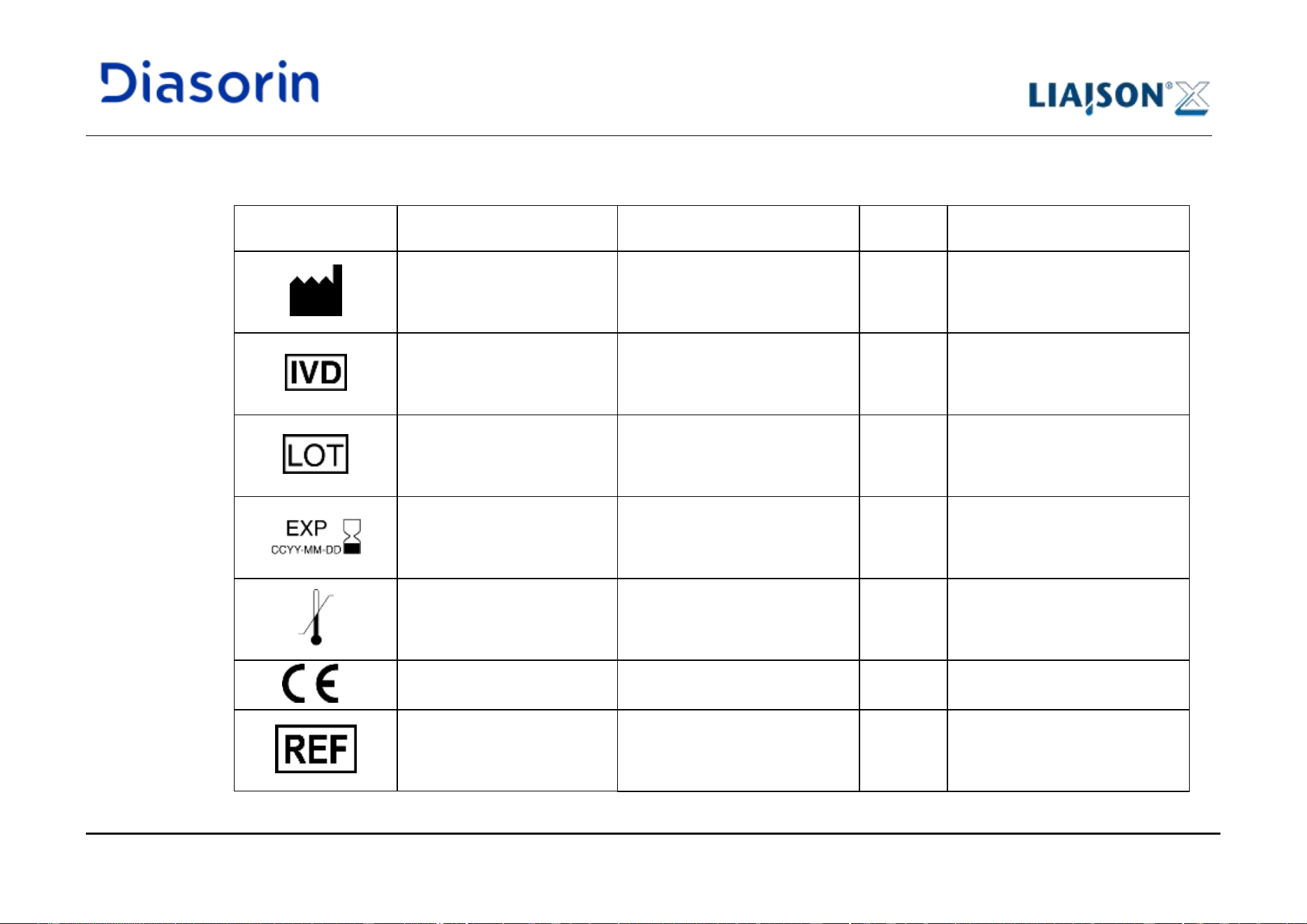
1.7.3 Other Symbols
Symbol
Title
Standard
Reference
number
Description
Manufacturer
ISO 15223-1: Medical Devices-
Symbols to be used with medical
device labels, labelling and
information to be supplied
5.1.1
Indicates the medical device
manufacturer, as defined in
EU Directives 90/385/EEC,
93/42/EEC and 98/79/EC.
In vitro diagnostic medical
device
ISO 15223-1: Medical Devices –
Symbols to be used with medical
device labels, labeling and
information to be supplied
5.5.1
Indicates a medical device that is
intended to be used as in vitro
diagnostic medical device.
Batch code
ISO 15223-1: Medical Devices –
Symbols to be used with medical
device labels, labeling and
information to be supplied
5.1.5
Indicates the manufacturer’s
batch code so that the batch or
lot can be identified.
Use-by date
ISO 15223-1: Medical Devices –
Symbols to be used with medical
device labels, labeling and
information to be supplied
5.1.4
Indicates the date after which the
medical device is not to be used.
Temperature limit
ISO 15223-1: Medical Devices –
Symbols to be used with medical
device labels, labeling and
information to be supplied
5.3.7
Indicates the temperature limits
to which the medical device can
be safely exposed.
CE mark
-
-
-
Catalogue Number
ISO 15223-1: Medical Devices –
Symbols to be used with medical
device labels, labeling and
information to be supplied
5.1.6
Indicates the manufacturer’s
catalogue number so that the
medical device can be identified.
1 Introduction
Page 1-10 LIAISON XL - Instructions for use
Rev. L
Symbol
Title
Standard
Reference
number
Description
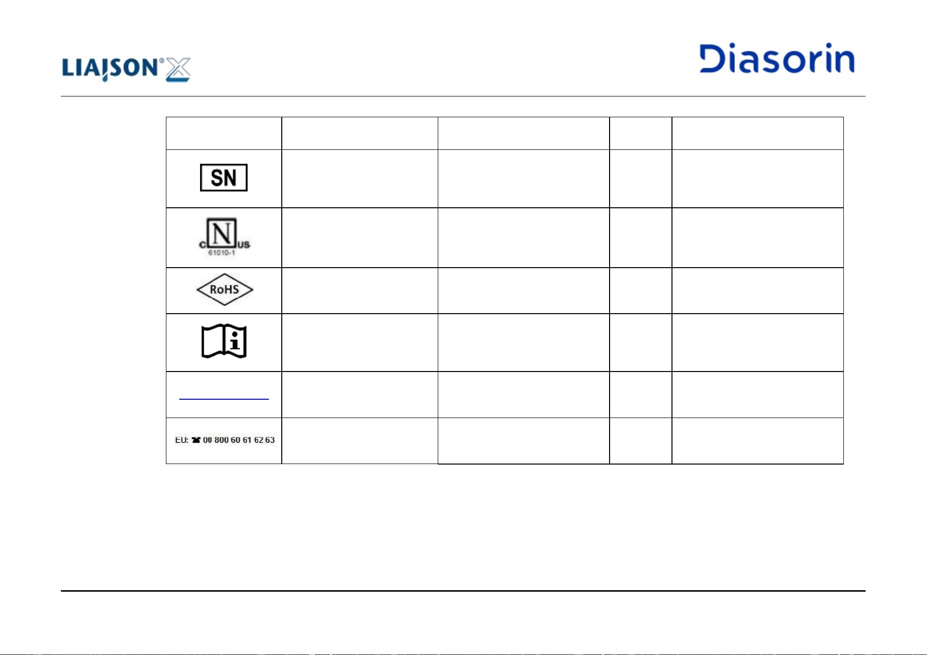
Serial number
ISO 15223-1: Medical Devices –
Symbols to be used with medical
device labels, labeling and
information to be supplied
5.1.7
Indicates the manufacturer’s
serial number so that a specific
medical device can be identified
Certification mark provided by
NEMKO for US and Canadian
Markets
-
-
-
RoHS compliance
-
-
-
Consult electronic instructions
for use
ISO 15223-1: Medical Devices –
Symbols to be used with medical
device labels, labeling and
information to be supplied
5.4.3
Indicates the need for the user to
consult the electronic instructions
for use
www.diasorin.com
DiaSorin website
-
-
-
Toll free number
-
-
-
1 Introduction
LIAISON XL - Instructions for use Page 1-11
Rev. L
Symbol
Title
Standard
Reference
number
Description
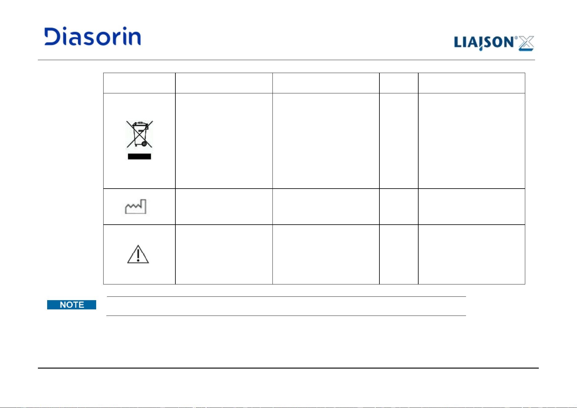
Disposal of Electrical and
Electronic Equipment
In the European Union,
electrical and electronic
equipment must not be
disposed of with other
household-type waste. It must
be collected separately.
Please observe the relevant
legal regulations effective in
the respective country.
-
-
-
Date of manufacture
ISO 15223-1: Medical Devices-
Symbols to be used with medical
device labels, labelling and
information to be supplied
5.1.3
Indicates the date when the
medical device was
manufactured.
Caution
ISO 15223-1: Medical Devices-
Symbols to be used with medical
device labels, labelling and
information to be supplied
5.4.4
Indicates the need for the user to
consult the instructions for use
for importatnt cautionary
information such as warnings
and precautions that cannot, for
a variety of reason, be presented
on the medical device itself.
For Customer Service in US and Canada call toll free: 1-800-328-1482
1 Introduction
Page 1-12 LIAISON XL - Instructions for use
Rev. L
1.8 Hazard Instructions
1.8.1 General Safety
The following safety instructions must be observed at all times, both before and during operation of the system.
The Instructions for use is provided for user safety and gives important instructions for the handling of the system described.
• Before starting use of the LIAISON
®
XL Diagnostic System, read the following explanations for safety carefully, and understand the
contents completely. User must be trained before being allowed to operate the system.
• Keep the Instructions for use near the system.
• When using reagents or chemicals, a properly well-ventilated room should be the responsibility of the user. Failure to comply may result in
health issues.
• For maintaining safety, do not modify the LIAISON
®
XL Diagnostic System, do not change the components or accessories, do not use
parts either than the specified, and do not remove the safety devices.
• Installation and service of the system or changes in the installation may never be performed by non-authorized persons not approved by
DiaSorin Italia S.p.A. Multiple plug sockets different from the one as installed by DiaSorin or its representative personnel are not allowed.
• Do not perform any operations or functions not described in the operating instructions. If trouble occurs on the Diagnostic System, contact
DiaSorin Italia S.p.A., or an authorized representative.
• Cautions indicated on the LIAISON
®
XL Diagnostic System and in the operating instructions are prepared after careful examination;
however, phenomenon beyond prediction may occur. When performing operation and maintenance, it is imperative to follow the
instructions correctly.
• It is mandatory to allow DiaSorin Italia S.p.A. personnel, or an authorized representative, to perform all scheduled and exceptional
interventions on the LIAISON
®
XL Diagnostic System that have been indicated as necessary to guarantee the full operational conditions
of the system.
• The Instructions for use must be accessible to the user at all times.
1 Introduction
LIAISON XL - Instructions for use Page 1-13
Rev. L
To guarantee the full operational conditions of the LIAISON
®
XL Diagnostic System, it is mandatory to allow DiaSorin
Italia S.p.A. personnel, or any field service authorized representative, to perform all scheduled (two preventive
maintenances per year) and unscheduled interventions, whereby required under particular circumstances, including
but not limited to inappropriate use, over extraordinary workloads or any inconsistent use in respect of DiaSorin
guidelines or recommendations. Ordinary analyzer workload is considered up to 500 determinations (assay results)
per day.
Failure to adhere to the IFU may result in harm for the user or 3
rd
party persons, damage to the system or
adversely affect assay result. See section Operational precautions and limitations, chapter 1.11.
1.8.2 Liability
The LIAISON
®
XL Diagnostic System is designed and manufactured in accordance with the safety requirements for electronic and medical
systems. It is the operators’ responsibility to comply with local and national law's regulations and laboratory procedures for installation and
operation of the instrument.
The manufacturer has done everything possible to guarantee that the equipment functions safely, both electrically and mechanically.
The systems are tested by the manufacturer and supplied in a condition that allows safe and reliable operation.
The information contained herein is based on experience and the best knowledge relating to the subject matter as acquired by
DiaSorin Italia S.p.A.
DiaSorin is not liable for any loss or damage, including consequential or special damages resulting from the use and or misuse of the
contained information be it negligence or other fault of personnel and/or contractors.
• The instrument may only be used in accordance with its intended use.
• Use only the consumables and accessories described herein (e.g. disposable tips, cuvettes).
• The manufacturer assumes no liability for any damages, including those to third parties, caused by improper use or handling of the
system.
1 Introduction
Page 1-14 LIAISON XL - Instructions for use
Rev. L
Improper use of the system may result in wrong assay results, damage of the system and personal injury.
1.8.3 Electrical Hazards
The LIAISON
®
XL Diagnostic System does not pose uncommon electrical hazards to operators if it is installed and operated without alteration
and is connected to a power source that meets required specifications. See Electrical requirements in chapter 10.1.
National rules and local regulations for the safe electrical operation of the system must be observed.
Basic electrical hazard awareness is essential to the safe operation of any system. Only qualified personnel should perform electrical
servicing.
Elements of electrical safety include, but are not limited to the following:
• Where appropriate, the Analyzer is installed with additional external switch for residual current circuit-breakers with over-current protection.
• Where appropriate it is integrated in UPS device.
• Use only connection and extension cables with a protective conductor and sufficient capacity (performance, power) to connect the system
and the peripheral devices to the mains supply.
• Use a properly grounded electrical outlet of correct voltage and current handling capability.
• Never interrupt the grounding contacts.
• Grounding of the system and its peripheral devices to the same protective earth potential must be ensured.
• The multi plug possibily supported can be used only as installed by DiaSorin or its representative personnel. Do not add any other device
to the supplied multi plug.
• Determine and correct the cause of a blown fuse or thrown circuit breaker before attempting to resume operation of the system.
• Do not disconnect any electrical connection or service any electrical or internal components while the power is on.
• Keep liquids away from all connectors of electrical or communication components.
• Do not touch any switches or outlets with wet hands.

1 Introduction
LIAISON XL - Instructions for use Page 1-15
Rev. L
• Keep the floor dry and clean under and around the Analyzer.
• Disconnect the Analyzer power cord before cleaning major liquid spills.
• Clean spilled fluids immediately.
• Damaged connecting cables must be replaced immediately.
• No objects may be placed on the connecting cables.
• Connecting cables must be routed so that they cannot be squeezed or damaged.
• Connecting cables must be routed so that they do not lie in accessible or drivable areas.
• Immediately separate the defective system from the mains supply, if a safe usage is no longer possible.
• Secure the defective system against reconnection.
• Label the defective system clearly as being defective.
• Switch off the system, separate it from the mains supply and protect it against restarting. When system is secured start cleaning,
disinfection, decontamination, maintenance or repair operations.
• Ensure that the system is free from personnel and that all covers are attached and closed before reconnecting the system to the mains
supply.
• Ensure the positioning of the system during installation is so that the power supply and mains switch are easily accessible.
Electrocution/Fire Hazard!
Non-observance of rules and regulations may cause serious personal injury with lethal consequences and material
damage.
Improper connection of the system and the peripheral devices to mains supply can cause serious personal injury with
lethal consequences and material damage (e.g. fire).
Damaged connecting cables can cause serious personal injury with lethal consequences and material damage (fire).
Defective systems can result in serious injury with lethal consequences and material damage (e.g. fire).
In case of accidental spilling or dropping on electrical or electronical parts or connections, switch off the system and
unplug from the mains supply. When the system is secured, call Service support.
1 Introduction
Page 1-16 LIAISON XL - Instructions for use
Rev. L
Danger of Electrocution or Mechanical Injury
If the system is not separated from the main supply before maintenance operations, serious injury with lethal
consequences due to electrocution may occur. Additionally, there is the danger that the system starts and may cause
injury (e.g. contusion, cuts etc.) to the person working with the system.
Danger due to Improper Positioning of Installation
Improper placement of the system can cause accidents with serious injuries with lethal consequences, fire or serious
system damages because the system cannot be switched off or be separated from the main supply.
1.8.4 Physical Hazards
1.8.4.1 Laser Light Hazards
• Never look directly into the laser beam.
• Do not introduce optical devices into the system.
• Remove watches and reflective jewelery before operating the laser.
• Caution during operation and testing the laser (bar-code scanner and handheld barcode reader) must be taken due to the laser class
(class 2).
Eye Injury due to Laser Radiation
Laser radiation can cause eye injury when looking into the laser beam for a long period of time.
Wrong usage of operating elements or of adjustments or the non-observance of processes can cause a dangerous
emission of laser radiation.
1 Introduction
LIAISON XL - Instructions for use Page 1-17
Rev. L
Do not use the handheld barcode reader for purposes different from reading bi-dimensional control definitions.
1.8.4.2 Heavy objects
• Use proper lifting techniques when handling full tanks (water, wash, and waste), the full waste basin and the full waste bin.
• Use care when handling the tanks to reduce the risk of injury.
• Use care when handling the waste basin and the waste bin, in order to avoid falls of contaminated materials.
1.8.4.3 Trip Hazards
The LIAISON
®
XL Diagnostic System is equipped with power cords and various computer connectors. To avoid tripping hazards, ensure
cords are properly stowed.
In the event of a damage, prejudice or personal injury occurring in connection with the use of the LIAISON
®
XL
Diagnostic System, user shall immediately contact the local DiaSorin Representative.
1.8.5 Mechanical Hazards
The LIAISON
®
XL Diagnostic System is an automated system that operates under computer control. As with most automated equipment,
there is potential for injury and bodily harm from moving mechanical components whenever the system is in operation.
The LIAISON
®
XL Diagnostic System minimizes mechanical hazards by providing guards to protect against accidental contact with moving
components, and encoding the software with safety features.
During operation of the Analyzer, user is potentially exposed to the following moving mechanical components:
• Pipettor arms and probes;
• Cuvette loading mechanism (auger);
• Cuvette orientation mechanism (sorter).
1 Introduction
Page 1-18 LIAISON XL - Instructions for use
Rev. L
Basic elements of mechanical safety include, but are not limited to:
• Avoid contact with the sharp metal edges.
• Never bypass or override a safety device.
• Keep all protective covers and barriers in place.
• Never perform manual tasks on the work surface of the system.
• Never allow any part of your body to enter a range of mechanical movement during system operation.
• Do not wear articles of clothing or accessories that could catch on the system.
• Keep pockets free of items that could fall into the system.
• The right pipettor probe is sharp and potentially contaminated with infectious material. Avoid contact with the probe tip.
• Do not attempt to resolve a cuvette jamming in the cuvette loader and sorter area when the Analyzer is running.
• Use caution when performing maintenance or cleaning procedures.
• Be aware that, in the event of a system malfunction or an unexpected sequence of movements, reflex actions could occur, causing injury.
• Select the placement of the system so that the ventilation slots are not blocked or covered.
• Select the placement of the system so that air can circulate.
• Never cover ventilation slots.
1 Introduction
LIAISON XL - Instructions for use Page 1-19
Rev. L
1.8.6 Biological Hazards
Performing the following activities user may be exposed to potentially infectious materials:
• Handling samples, reagents, calibrators, and controls;
• Cleaning spills;
• Handling and disposing of waste;
• Performing maintenance procedures;
• Performing cleaning or decontamination procedures.
The following information will help the user in minimizing the impact of this exposure.
User should consider all clinical samples, reagents, calibrators, controls, and used reaction vessels and consumables (e.g. tips, cuvettes) that
contain human-sourced material as potentially infectious. User should consider all system surfaces or components that have come in contact
with human-sourced material as potentially infectious. No known test method can offer complete assurance that products derived from human-
sourced material will not transmit infection. Therefore, all products derived from human-sourced materials and system components exposed to
human-sourced materials should be considered potentially infectious.
Precautions include, but are not limited to the following:
• Observe local and national provisions, legislation and laboratory regulations.
• Use appropriate disposable gloves.
• Use an appropriate lab coat.
• Use an appropriate eye protection.
• Avoid contact between skin/mucous membrane and samples/test reagents or parts of the instrument.
• Do not pipette by mouth.
• Do not eat, drink, smoke, apply cosmetics or handle contact lenses when handling human-sourced material or contaminated system
components.
• Use proper personal protective equipments when interacting with the probe for maintenance or cleaning procedures.
• Clean, disinfect and decontaminate the system immediately if potentially infectious material has been spilled.
1 Introduction
Page 1-20 LIAISON XL - Instructions for use
Rev. L
• Any reagent spills should be washed with a chemical use sodium hypochlorite solution with 0.5% active chlorine (e.g. dilution 1:10 of a
solution at 5% active chlorine) and disposed of as though potentially infectious.
• All samples, biological reagents and materials used in the assays must be considered potentially able to transmit infectious agents.
They should therefore be decontaminated and disposed of in accordance with the prevailing regulations and guidelines of the agencies
holding jurisdiction over the laboratory, and the regulations of each Country.
• Liquid waste must be decontaminated with a chemical use sodium hypochlorite solution with 0.1% active chlorine (e.g. dilution 1:50 of a
solution at 5% active chlorine) for at least half an hour.
• Do not use broken or chipped tubes or bottles.
• Observe the instructions in the package inserts for a correct use of the reagents.
Risk of infection!
All internal parts of the system, that are not defined as user interfaces and for which specific procedures are
described, must be treated as being potentially infectious. Improper handling of infectious parts can cause skin
irritations, illnesses and possibly death.
Disposal of Infectious Waste
Potential infectious material and all parts that may come in contact with potential infectious material must be
disposed according to the local and national provisions, legislation and laboratory procedures.
1 Introduction
LIAISON XL - Instructions for use Page 1-21
Rev. L
1.8.7 Chemical Hazards
User may be exposed to hazardous chemicals when handling reagents, calibrators and controls.
Exposure to hazardous chemicals is minimized by following instructions provided in the assay-specific documentation (such as a package
insert) and on product-specific labels, and product-specific MSDS (Material Safety Data Sheets).
In general, observe the following precautions when handling chemicals:
• Consult MSDS for safe use instructions and precautions.
• Avoid contact with skin and eyes. If contact with material is anticipated, wear impervious gloves, protective eye wear, and clothing.
• Maintain good housekeeping. Do not eat, drink, or store food and beverages in areas where chemicals are used.
• Seek medical attention if irritation or signs of toxicity occur after exposure.
1.8.8 Spill clean-up
Clean spills in accordance with established biosafety practices and follow instructions in the MSDS (Material Safety Data Sheets). In general,
safe work practices for cleaning spills include:
• Wear appropriate personal protective equipment, such as gloves, eye wear and lab coat.
• Absorb the spill with absorbent material.
• Wipe the area clean with an appropriate disinfectant such as a chemical use sodium hypochlorite solution with 0.5% active chlorine
(e.g. dilution 1:10 of a solution at 5% active chlorine).
1.8.9 Waste handling and disposal
Each facility is responsible for labeling all waste tanks and characterizing its waste stream to ensure waste is disposed in accordance with the
appropriate local regulations.
See the manufacturer's assay-specific documentation (such as a package insert or reagent application sheet), the product-specific label, or
the product-specific MSDS (Material Safety Data Sheet).
1 Introduction
Page 1-22 LIAISON XL - Instructions for use
Rev. L
1.8.10 Caution on electromagnetic wave interference
1.8.10.1 Electromagnetic wave interference given by LIAISON
®
XL to other equipment
The LIAISON
®
XL Analyzer has been designed and manufactured in compliance to the applicable EMC standards.
Use the cables attached at the installation for connection between the devices in the system. The proper use of the specified cables minimizes
electromagnetic wave interference.
Installation and service of the system or changes in the installation may never be performed by non-authorized persons not approved by
DiaSorin Italia S.p.A. Movable multiple plug sockets different from the one installed by DiaSorin personnel are not allowed.
However, there is no guarantee that the LIAISON
®
XL Analyzer will not cause electromagnetic wave interference.
a. When the LIAISON
®
XL Analyzer may be the cause, turn off the power of this Instrument and check radio and television
reception.
b. If it is improved, the LIAISON
®
XL Analyzer probably is the cause.
1.8.10.2 Electromagnetic wave interference that may be given to the LIAISON
®
XL Analyzer
If the LIAISON
®
XL Analyzer is used near equipment that generates strong electric and magnetic field, noises may enter the Instrument to
affect the performances and functions.
Use the cables attached at the installation for connection between the devices in the system. The proper use of the specified cables minimizes
electromagnetic wave interference.
Installation and service of the system or changes in the installation shall be performed only by authorized persons approved by
DiaSorin Italia S.p.A. Movable multiple plug sockets different from the one installed by DiaSorin personnel are not allowed.
However, there is no guarantee that the LIAISON
®
XL Analyzer will not be affected by electromagnetic wave interference.
a. When other equipment may be the cause, turn off the power of the equipment and check the functions of the LIAISON
®
XL
Analyzer.
b. If they are improved, interference from the equipment is probably the cause.
1 Introduction
LIAISON XL - Instructions for use Page 1-23
Rev. L
Try the following to correct the issues.
a. Move the LIAISON
®
XL Analyzer further away from the equipment that may be the cause.
b. Connect the power cord of the LIAISON
®
XL Analyzer to an outlet that is on a different circuit from the equipment that may be the
cause.
c. Check the electromagnetic wave interference does not affect the other equipment, which is connected with this Analyzer.
Transient Emissions and Interference Resistance
The instrument meets the requirements described in standard IEC 61326 on transient emissions and interference
resistance.
• This instrument was developed and tested according to CISPR11 Class A. It can cause radio interference in
domestic environment. In this case it may be required to take action to eliminate such interference.
• Before setup and operation of the instrument, the electromagnetic environment should be evaluated.
• Do not use the instrument in the vicinity of sources with excessive electromagnetic radiation (e.g. unshielded,
deliberately operated high frequency sources) since they could interfere with the proper operation of the
instrument.
1.8.10.3 EMC Compliance
The LIAISON
®
XL Analyzer has been tested according to the method of IEC 61326-1 and IEC 61326-2-6 using the threshold reported in the
Electromagnetic compatibility (EMC) standard IEC 60601-1-2:2014+A1:2020 Medical electrical equipment - Part 1-2: General requirements for
basic safety and essential performance - Collateral Standard: Electromagnetic disturbances - Requirements and tests.
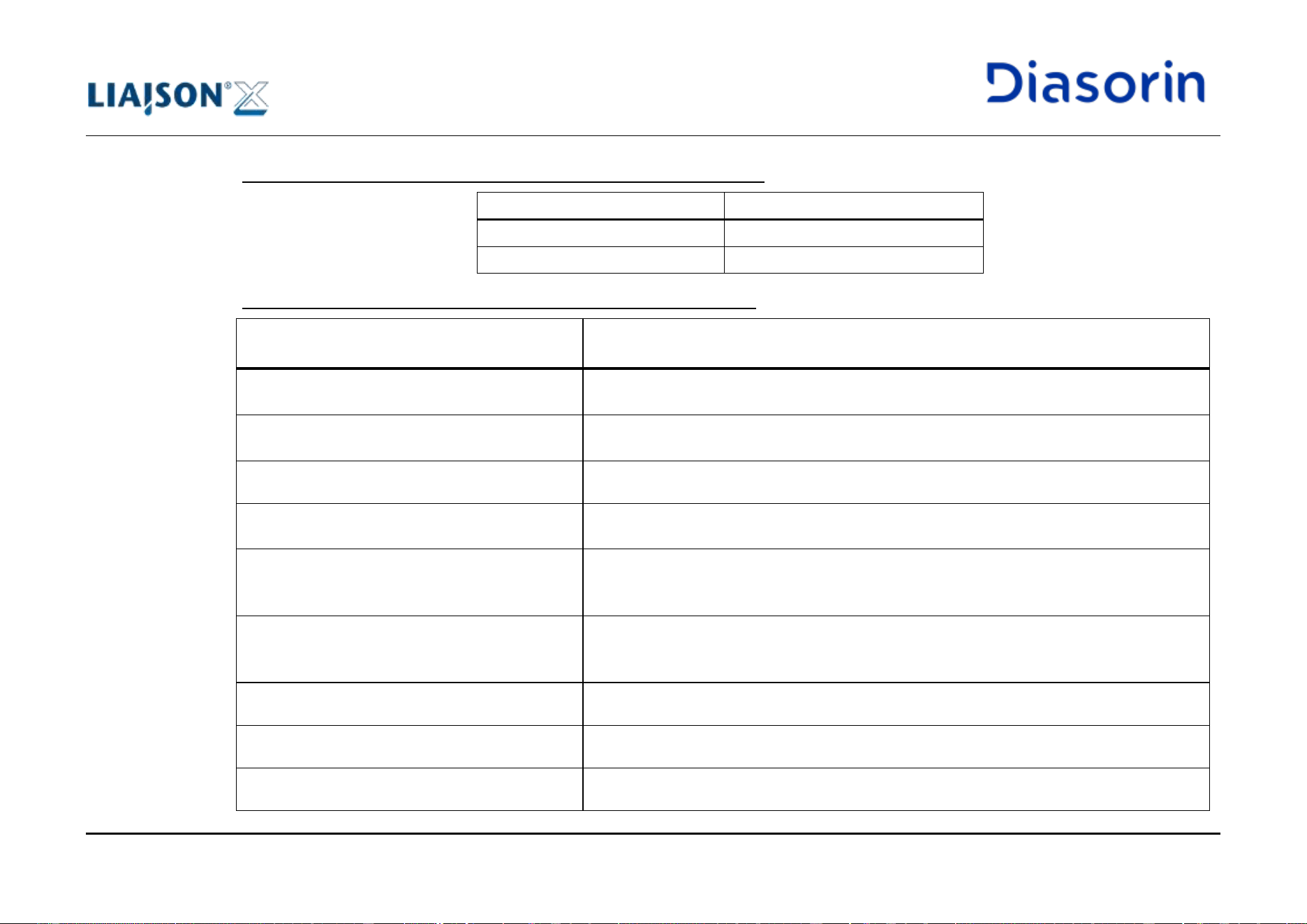
The LIAISON
®
XL Analyzer is intended for use in the electromagnetic environment specified below. The customer or the user of the
LIAISON
®
XL Analyzer should assure that it is used in such an environment.
1 Introduction
Page 1-24 LIAISON XL - Instructions for use
Rev. L
Guidance and Manufacturer's Declaration - Electromagnetic Emissions
Emission tests
Compliance
RF emissions CISPR 11
Group 1
RF emissions CISPR 11
Class A
Guidance and Manufacturer's Declaration - Electromagnetic Immunity
Immunity Test
Compliance Level Against
IEC 60601-1-2:2014+A1:2020
Electrostatic discharge (ESD)
IEC 61000-4-2
Contact: ± 8 kV
Air: ± 2 kV, ± 4 kV, ± 8 kV, ± 15 kV
Radiated Immunity Testing
IEC 61000-4-3
3 V/m 80-2700 MHz 1kHz 80% am
9-28 V/m 385-6000 MHz pulse mode
Electrical fast transient/burst
IEC 61000-4-4
Power Supply Lines at 100 kHz, ± 2.0 kV
Surge
IEC 61000-4-5
Line to Line: ± 1.0 kV
Line to ground: ± 2.0 kV
Conducted Immunity Testing
IEC 61000-4-6
3 V: 0.15 – 80 MHz
6V: In ISM Bands between 0.15 MHz and 80 MHz
80 % AM at 1 kHz
Voltage dips
IEC 61000-4-11
0 % UT; 0,5 cycle, At 0°, 45°, 90°, 135°, 180°, 225°, 270° and 315°
0 % UT; 1 cycle and 70 % UT; 25/30 cycles
Single phase: at 0°
Voltage interruptions
IEC 61000-4-11
0 % UT; 250/300 cycle
Power frequency (60 Hz) magnetic field
IEC 61000-4-8
30 A/m at 60 Hz
Proximity to Magnetic Fields
IEC 61000-4-39
134.2 kHz and 13.56 MHz
1 Introduction
LIAISON XL - Instructions for use Page 1-25
Rev. L
• No essential performance has been identified, loss of clinical function will not result in any unacceptable risk.
• Use of this equipment stacked with another equipment is not allowed.
• Avoid using the equipment close to another equipment. If such use is necessary, this equipment and the other equipment should be
observed to verify that they are operating normally.
• Use of cables other than those specified or provided could result in increased electromagnetic emissions or decreased electromagnetic
immunity of this equipment and result in improper operation.
Electromagnetic Interference (EMI)
This equipment has been tested and found to comply with the requirements of IEC 60601-1-2 for electromagnetic
compatibility. However, to help ensure optimal performance and continued safe operation, avoid placing the device in
close proximity to sources of radio frequency (RF) emissions. These include, but are not limited to:
• Mobile phones and wireless communication devices (including 5G millimeter wave)
• RFID readers and EAS (Electronic Article Surveillance) systems
• Wireless Power Transfer devices
• Wireless routers and Bluetooth transmitters
• Industrial equipment generating strong electromagnetic fields
1.8.11 Static magnetic field
Magnets are used in the Washer module, Front module, and Left Arm Pipettor of the instrument. Concerning precautionary limits of exposure
to magnetic fields, international standards establish 0.5 mT (5 gauss) as the magnetic flux density threshold level for static magnetic fields to
prevent inadvertent harm to persons with implanted electronic medical devices and implants containing ferromagnetic material. The 5 gauss
line of all magnets in the instruments are either completely within the instrument or are exceeding it to an extent which is not expected to have
impact on the user during normal operations.
1 Introduction
Page 1-26 LIAISON XL - Instructions for use
Rev. L
1.8.12 FCC Radio User Manual Guidance
This equipment has been tested and found to comply with the limits for a Class A digital device, pursuant to Part 15 of the FCC Rules.
These limits are designed to provide reasonable protection against harmful interference when the equipment is operated in a commercial
environment. This equipment generates, uses, and can radiate radio frequency energy and, if not installed and used in accordance with the
instruction manual, may cause harmful interference to radio communications. Operation of this equipment in a residential area is likely to
cause harmful interference in which case the user will be required to correct the interference at his own expense.
Changes or modifications not expressly approved by the party responsible for compliance could void the user’s authority to operate the
equipment.
1.9 Safety residual risks for User
The aim of this section is to bring to user’s attention the status of residual risks despite the inherent safe design measures, safeguarding and
complementary protective measures adopted by the Manufacturer to lower the risks to an acceptable level.
User must read carefully this section to understand the residual risks and learn the recommended instructions to work safely with the
LIAISON
®
XL Diagnostic System.
If further clarification should be needed, it is recommended to contact the local DiaSorin representative.
1.9.1 Definitions
(a) "hazard" means a potential source of injury or damage to user’s health;
(b) "danger zone" means any zone within and/or around machinery in which a user is subject to a risk to his/her health or safety;
(c) "exposed person" means any user wholly or partially in a danger zone;
(d) "user" means the person or persons operating, maintaining and cleaning the machinery;
(e) "risk" means a combination of the probability and the severity of an injury or damage to health that can arise in a hazardous situation;
(f) "guard" means a part of the machinery used specifically to provide protection by means of a physical barrier;
(g) "protective device" means a device (other than a guard) which reduces the risk, either alone or in conjunction with a guard;
1 Introduction
LIAISON XL - Instructions for use Page 1-27
Rev. L
(h) "intended use" means the use of machinery in accordance with the information provided in the instructions for use;
(i) "reasonably foreseeable misuse" means the use of machinery in a way not intended in the instructions for use, but which may result from
readily predictable human behaviour.
1.9.2 Inherent safe design and manufacturing process
The Analyzer has been designed and manufactured following the applicable regulations and harmonized standards.
In regards of risk management, the Analyzer has been designed and manufactured applying a risk management process, based upon the
ISO standard 14971:2007 (Medical devices – Application of risk management to medical devices). By the application of the standard, through
an iterative process of risk analysis, the manufacturer has:
• Determined the limits of the Analyzer, which include the intended use and any reasonably foreseeable misuse;
• Identified the hazards and the associated hazardous situations that can be generated by the use of the machinery;
• Estimated the risks for hazardous situations, taking into account the severity of the potential harm (injury or damage to health) and the
probability of its occurrence by the application of an appropriate FMEA (Failure Mode Effect analysis) methodology;
• Evaluated the risks, with a view of determining whether risk reduction has been required;
• Reduced the risk for hazardous situations by the identification, implementation and verification of the effectiveness of appropriate risk
control measures.
The above mentioned process will be actively maintained by the Manufacturer until the retirement of the LIAISON
®
XL Diagnostic System
from the market. The Manufacturer has also established procedures to review post production information in order to ensure the appropriate
safety degree and to maintain the IVD Analyzer always adequate to the so called “state of the art” as per, and in compliance with, the
European Community Regulation 746/2017 related to IVD Medical Devices.
The LIAISON
®
XL Diagnostic System has been designed and constructed so that it is fitted for its function, and can be operated, adjusted and
maintained without putting persons at risk when these operations are carried out under the conditions foreseen, but also taking into account
any reasonably foreseeable misuse thereof.
The aim of measures taken is to eliminate any risk throughout the foreseeable lifetime of the machinery including the phases of transport,
assembly, dismantling, disabling and scrapping.
1 Introduction
Page 1-28 LIAISON XL - Instructions for use
Rev. L
In selecting the most appropriate methods, DiaSorin has applied the following principles, in the given order:
• to eliminate or to reduce risks as far as possible (inherently safe machinery design and construction),
• to take the necessary protective measures in relation to risks that cannot be eliminated,
• to inform users of the residual risks due to any shortcomings of the protective measures adopted,
• to indicate whether any particular training is required and specify any need to provide personal protective equipment.
Where possible, the Analyzer has been designed and constructed to prevent abnormal use if such use would create a risk.
Where appropriate, the instructions draw the user's attention to ways — if the experience has shown might occur — in which the machinery
should not be used. The instructions have to be carefully read, paying attention to all warnings, taking into account the way the Analyzer has
to be operated and which are the abnormal uses forbidden.
The LIAISON
®
XL Diagnostic System is supplied with all the special equipments and accessories essential to allow safely using and
maintaining. No other tools from the ones supplied by the Manufacturer must be used; use of unapproved items may endanger user’s safety
and/or health.
In no event shall DiaSorin Italia S.p.A. or its affiliates be liable for any damages or losses incurred in connection with
or arising from the use of unapproved items used to operate or maintain the Analyzer.
1.9.3 Materials and products
The materials and products of which the Analyzer is made and the agents and reagents used on it do not endanger the user’s safety or health,
apart from remaining biohazard and chemical risks and the interference they might cause with electrical and mechanical risks. In particular, in
the areas where biological fluids are used, the Analyzer has been designed and constructed to prevent risks due to filling, use, recovery or
draining.
1 Introduction
LIAISON XL - Instructions for use Page 1-29
Rev. L
1.9.3.1 Waste liquid tank
When user removes one waste liquid tank to empty it, he/she has to disconnect the level sensor first and then the tubing; reinserting the tank
in the Analyzer, user is required to reconnect the tubing first and then the level sensor, to prevent the risk of leakage due to a missing
reconnection of the tubing.
If one waste tank level sensor is not correctly reconnected, the Analyzer stops using it. The same occurs if the level
sensor is out of order.
The joint connector allows to manage the insertion/ removal of waste sensor and tubing as a single task.
See chapter 5.5.6 for details.
For safe use it is strictly forbidden:
• to alter or modify the level sensor function and/ or use Analyzer without liquid waste tank correctly connected to
the tubing, apart if a direct drain connection (see chapter 4.2.9.6) is used for waste disposal;
• to use cracked or broken tanks.
During a liquid waste tank disconnection, the user has to prevent dripping of infectious liquid from the tubing waste, when unplugging it.
The user has to wear gloves, lab coat and use paper to dry the tubing. In order to minimize the possibilities of contamination of cabinet areas,
a specific slot of the waste basin shall be used to position disconnected waste sensors and tubings (applicable to instruments with cabinet
drawers).
After the tubing and level sensor have been disconnected, the user is asked to carefully handle the tank to prevent spillage and corner, edge
or side shocks.
If an accidental tank shock should occur, before reassembling the tubing and sensor, the user is asked to accurately check the plastic surface
to detect whether any crack or break occurred. If any crack or break is detected, the tank must not be used and it must be replaced.
The assessment about residual risks has highlighted that a tank crack generated by a shock may also not be detected by the user. In this
case a basin can prevent the spillage; because of shape, dimensions and volumes, it does not produce other risks for handling or mechanical
interference.
1 Introduction
Page 1-30 LIAISON XL - Instructions for use
Rev. L
1.9.4 Design of Analyzer to facilitate handling
Where appropriate, according with remaining risks evaluation results, tanks are equipped with handles in order to facilitate gripping; because
of shape, dimensions and volumes, it does not produce other risks for handling or mechanical interference.
1.9.5 Ergonomics
The LIAISON
®
XL Diagnostic System has been designed taking into account the ergonomic principles to reduce at minimum discomfort,
fatigue, physical and psychological user’ stress under the intended conditions of use.
1.9.6 Safety and reliability of control systems
Control systems are managed in the Analyzer control software. A fault in the hardware or in the software of the control system does not lead
to hazardous situations: in case of HW or SW fault the Analyzer cannot work.
Software interface of Analyzer is validated against foreseeable risks: errors in the control system logic do not lead to hazardous situations.
The software is designed to help the user in following the right sequence of operations to be performed to run the Analyzer. Reasonably
foreseeable human errors during operation do not lead to hazardous situations. The Analyzer cannot start un-expectedly because there are
several operations to perform before having it started.
The parameters of the machinery do not change in an uncontrolled way, and may not lead to hazardous situations: the system set up
parameters are not accessible to users. They are managed by Field Service Engineers only.
If the stop command has already been given, the Analyzer cannot be prevented from stopping.
No moving parts of the machinery or pieces held by the Analyzer can fall or be ejected: there are no parts that fall as consequence of a stop
command.
Where applicable, a tip could be ejected into the appropriate waste solid bag as a consequence of a stop command. It does not lead to risks
because it is part of the intended use of the Analyzer.
It is strictly forbidden using the Analyzer with the solid waste container closed without the solid waste bag on. A SW counter notifies the user
when the solid waste bag is full and needs to be replaced. To ensure an appropriate replacement of the waste bag without affecting the
ongoing operation of the Analyzer, the system allows 15’ from the opening to the closing of the solid waste container, due to the presence of
an intermediate case. User is asked to wear gloves when handling the solid waste container and bag.
1 Introduction
LIAISON XL - Instructions for use Page 1-31
Rev. L
1.9.6.1 Main Cover Opening before or after a “moving” status – safe use
The interlock protective device (i.e the cover sensor) remains fully effective or gives a stop command also in case is out of order. In particular
intended uses, because of specific requirement related to initializing, diagnostic, service or maintenance status and different access profile
levels, opening the interlocked cover does not set the Analyzer to a stop command. In details, the System behaves as follows:
• Whenever the system is in status “initializing” and the main cover will be recognized as open, then the System stops moving; in case the
user access level is an end-user level (strictly lower than Field Service Engineer level) the consequence will be that, within a few seconds,
the Analyzer will stop all movements;
• The same would be true if the main cover opening occurs in combination with the status “maintenance”, in case the user access level is
an end-user level (strictly lower than Field Service Engineer level);
• The same would be true if the main cover opening occurs in combination with the status “running”, in case the user access level is an end-
user level (strictly lower than Field Service Engineer level);
• In case the main cover opening occurs in combination with the status “service” (i.e. during a diagnostic task), then the open cover
condition will be ignored, as there is a pop-up (given at the beginning of a diagnostic action) that reminds to close covers;
• If the SW will not be communicating with the Analyzer (e.g. if the PC should be switched off), then the Analyzer will halt itself anyway
(within about 4 seconds);
• If the main cover is opened while the pipettor arms are working during a routine, the System will stop the ongoing routine and get the
status “halted”; the routine interruption may be avoided pressing the button “Pause” and waiting for no less than 30’’ before opening the
cover. In both cases there is no risk of moving pipettor arms while the cover is open.
It is strictly forbidden to alter and / or to modify the intended use conditions and functions of interlocked cover.
When open cover condition is ignored, it is strictly forbidden to touch moving parts while running or getting closed to
them with hands, arms, shoulders or face/ head.
No operation must be performed touching moving parts while they are running!
1 Introduction
Page 1-32 LIAISON XL - Instructions for use
Rev. L
The EMERGENCY STOP can be obtained by cutting energy supply acting on the MAIN SWITCH.
An emergency stop device would not lower the risk because it would not reduce the stopping time in comparison with
the Analyzer’s main switch.
1.9.6.2 Emergency stop – safe use
The following conditions may occur and have to be followed after an emergency stop is given:
• after the instrument is turned back on, the software believes that the communication with the Analyzer is lost and it will interrupt the
communication;
• whenever the PC and the Analyzer are turned on together, there will be no movement at all, and the communication will be kept off; in
order to start the communication up, the only way is that the user will press the “Init” button in the software;
• any other action performed before or after turning on the Analyzer will not start the communication up, therefore nothing will move on the
machinery;
The emergency stop function of the main switch is available and operational at any time, regardless of the operating
mode.
1 Introduction
LIAISON XL - Instructions for use Page 1-33
Rev. L
1.9.7 Failure of the power supply
The interruption, the re-establishment after an interruption or the fluctuation in whatever manner of the Analyzer power supply does not lead to
dangerous situations.
Particular attention must be paid on the following aspects:
• the Analyzer does not start unexpectedly: a SW command given by the user is always necessary to restart movements of the Analyzer;
• the setting parameters of the Analyzer do not change in an uncontrolled way when in case power supply fluctuations or failures should
occur, not therefore leading to hazardous situations; such parameters are not erasable by the electrical power interruption;
• the Analyzer is not prevented from stopping if the command has already been given;
• no moving parts of the Analyzer or pieces held by it can fall or are ejected in case of power supply failure;
• automatic or manual stopping of the moving parts, whatever they may be, are unimpeded;
• the protective devices remain fully effective or give a stop command also in case they are out of order (please: read also chapter 1.9.6.1).
1.9.8 Protection against mechanical hazards
The durability of the materials used is adequate for the nature of the working environment foreseen by DiaSorin Italia S.p.A., in particular as
regards the phenomena of fatigue, ageing, corrosion and abrasion. To date, there is no evidence of parts showing to be weak.
Insofar as their purpose allows, accessible parts of the Analyzer have no sharp edges, no sharp angles and no rough surfaces likely to cause
injury.
The moving parts of the Analyzer are designed and constructed in such a way as to prevent risks of contact which could lead to accidents or,
where risks persist, are fitted with guards or protective devices or warning signals.
A remaining mechanical hazard is related to moving parts.
1 Introduction
Page 1-34 LIAISON XL - Instructions for use
Rev. L
Even if the residual mechanical risk is deemed acceptable, the user might be exposed to biohazard risk in case of
minor injury (e.g. cut or scratch).
To prevent mechanical risk, user must not stand close to moving parts of the Analyzer when the routine is running.
To prevent biohazard risk, user must wear the personal protective device as per Good Laboratory Practice and
according to local regulations.
For safe use it is strictly prohibited:
• to touch moving parts of the Analyzer while they are running;
• to touch Analyzer parts, accessories or tools potentially infected without wearing the personal protective devices;
• to assemble / disassemble tanks tubings without wearing glasses or a protective mask or visor;
• to handle samples, reagents or any other biological liquid or agent without wearing coat and gloves;
• to enter the loading bay for sample racks with hand or fingers while the Analyzer is running;
• to alter and or to modify fixed or interlocked movable guards;
• to use the Analyzer in end-user intended use without fixed or interlocked movable guards.
1.9.9 Protection against electrical hazards
The LIAISON
®
XL Diagnostic System is designed, constructed, equipped and installed in such a way that all hazards of an electrical nature
are or can be prevented. The Analyzer is designed and constructed to prevent or limit the build-up of potentially dangerous electrostatic
charges.
Where appropriate, the Analyzer is installed with additional external switch for residual current circuit-breakers with over-current protection.
Where appropriate it is integrated in UPS device.
National rules and local regulations for the safe electrical operations of the system must be strictly observed.
1 Introduction
LIAISON XL - Instructions for use Page 1-35
Rev. L
The Analyzer is not designed and constructed to be operated in a potentially explosive atmosphere. The Analyzer
must not be installed and used in a laboratory with potentially explosive atmosphere.
End user is responsible to assess that such requirement is respected before allowing DiaSorin Italia S.p.A. or its
affiliates to install the Analyzer.
For safe use it is strictly prohibited:
• To interrupt the electrical grounding contacts;
• To add any other device to the multi plug supplied with the Analyzer (if available) with the exception of those
installed by DiaSorin authorized representatives;
• To damage connecting cables or not replacing them if damaged;
• To place objects on the connecting cables;
• To leave connecting cables in accessible or drivable areas where they can become additional risk;
• To not immediately disconnect the Analyzer from the main supply, if a safe usage is no longer possible;
• To cover the switches or have them inaccessible;
• To use the Analyzer if any switch or controls device is damaged.
1.9.10 Protection against noise hazards
Analyzer is designed and constructed in such a way that risks resulting from the emission of airborne noise are reduced to the lowest level,
taking account of technical progress and the availability of means of reducing noise, in particular at source. For technical data regarding noise
emission, refer to chapter 10.8.
The A-weighted emission sound pressure level at workstations does not exceed 70 dB(A).
1 Introduction
Page 1-36 LIAISON XL - Instructions for use
Rev. L
1.10 Instrument Labelling and Safety Labels
This section provides information on the instrument labelling, with particular focus on the safety labels.
Safety labels are used on the LIAISON
®
XL system and in the documentation to identify potentially dangerous conditions. Before starting to
use the Analyzer, user has to identify these labels and understand the type and degree of potential hazard.
Missing Warnings
Missing or unreadable warning labels or type labels can result in non-identified dangers which can cause serious
personal injury and/or material damage.
• Check the system for missing or unreadable warning labels and type labels.
• Missing or unreadable warning labels or type labels must be replaced.
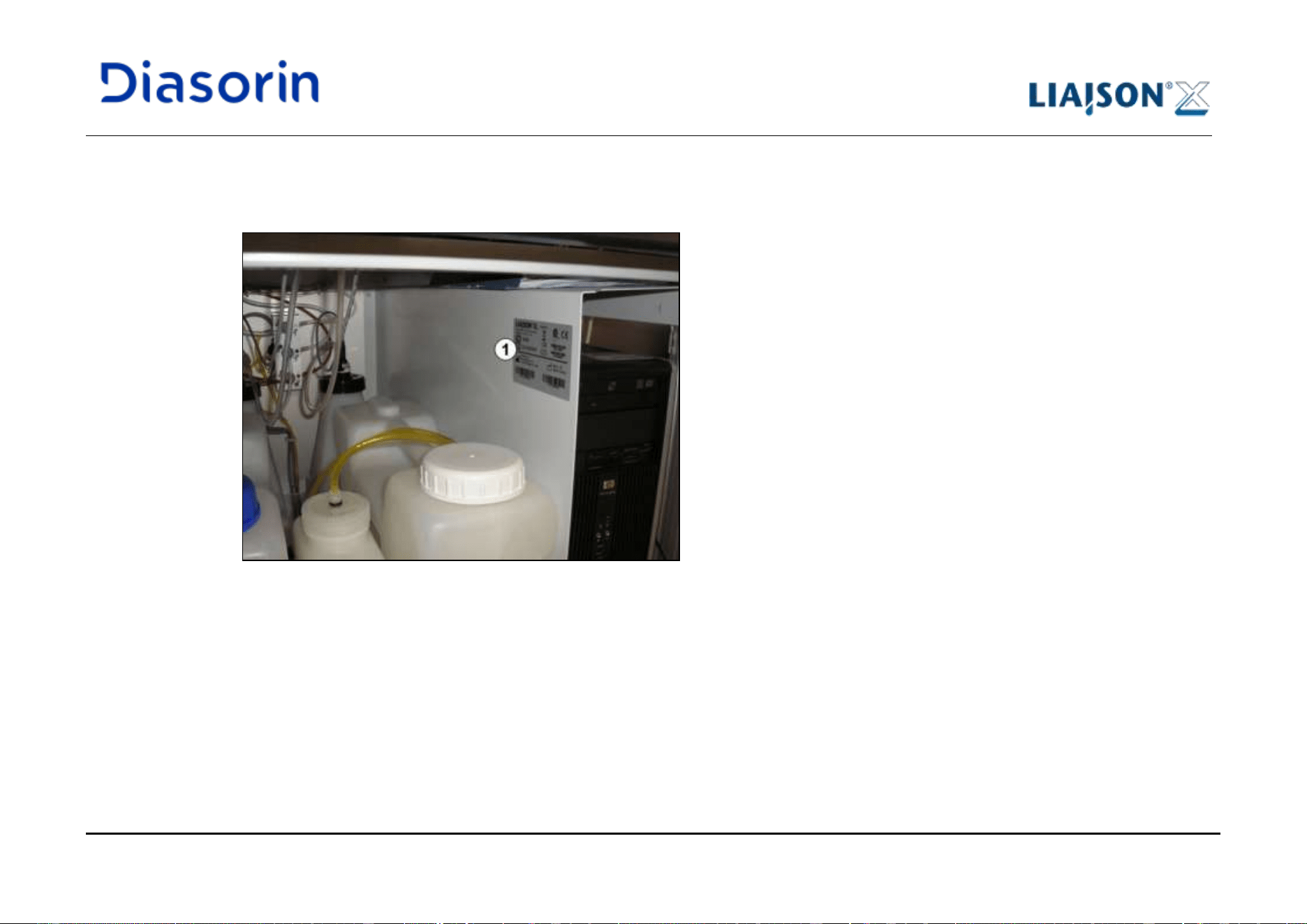
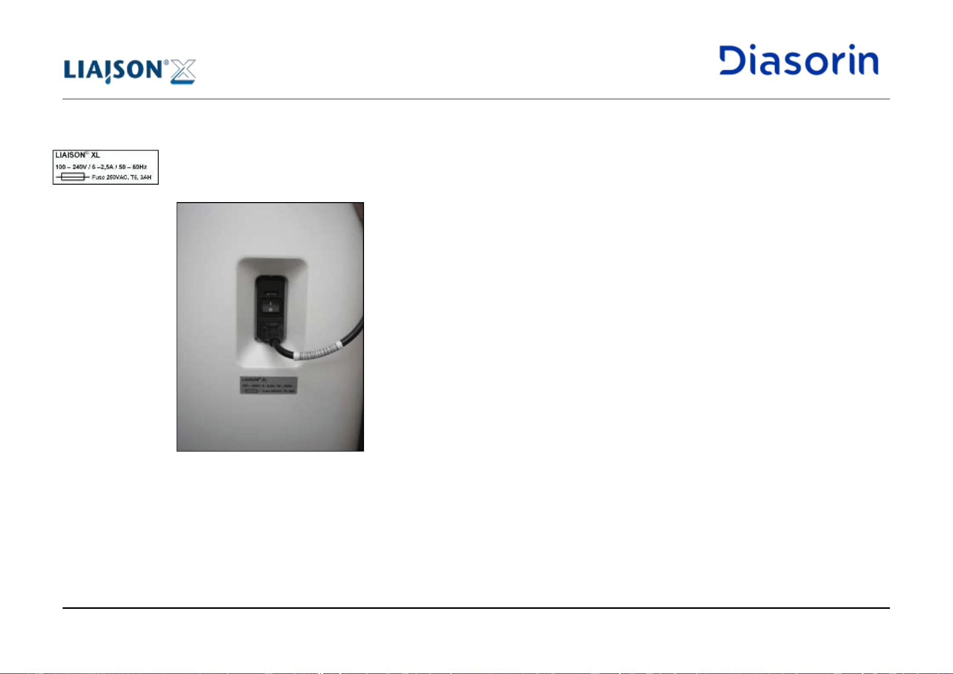
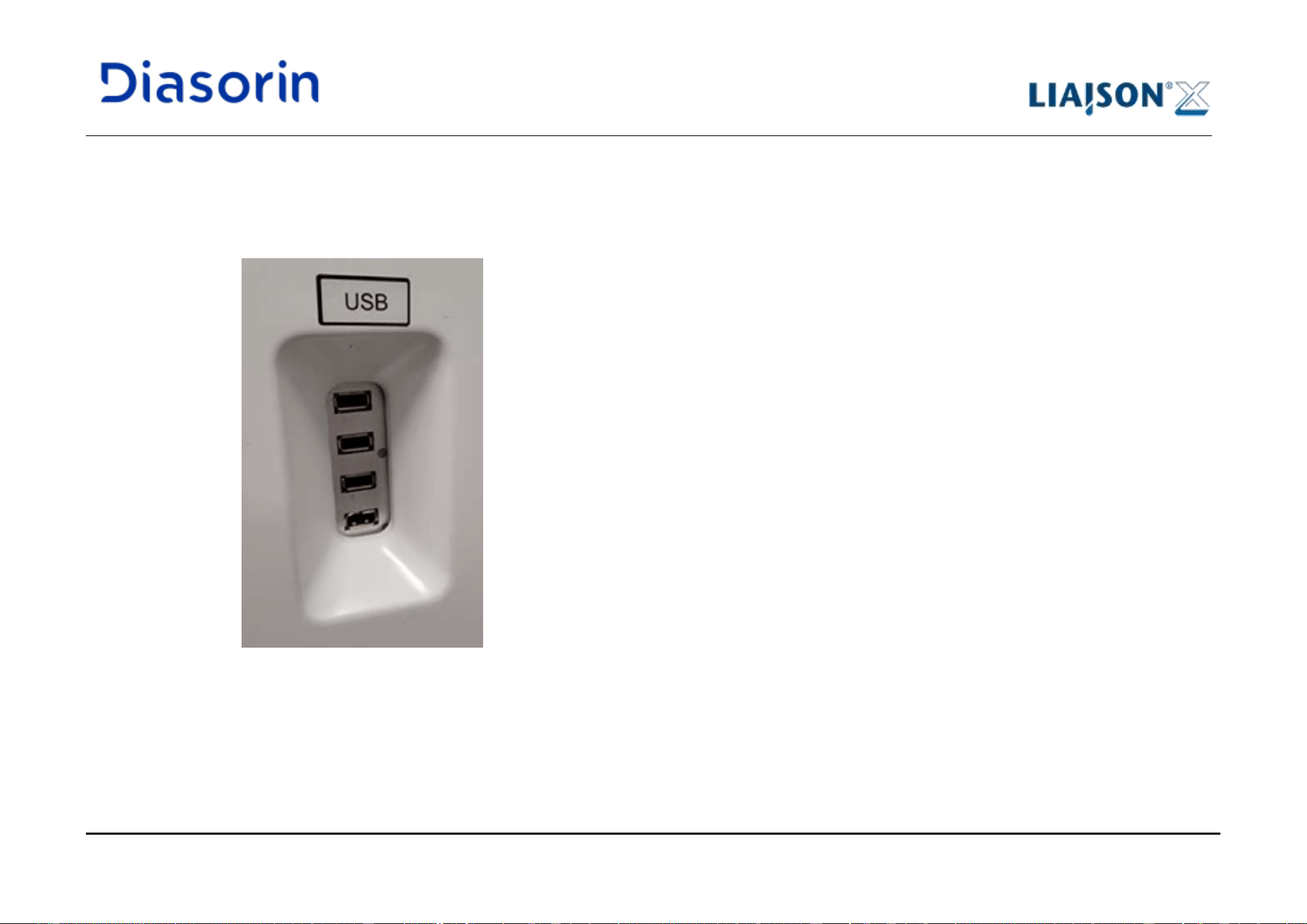
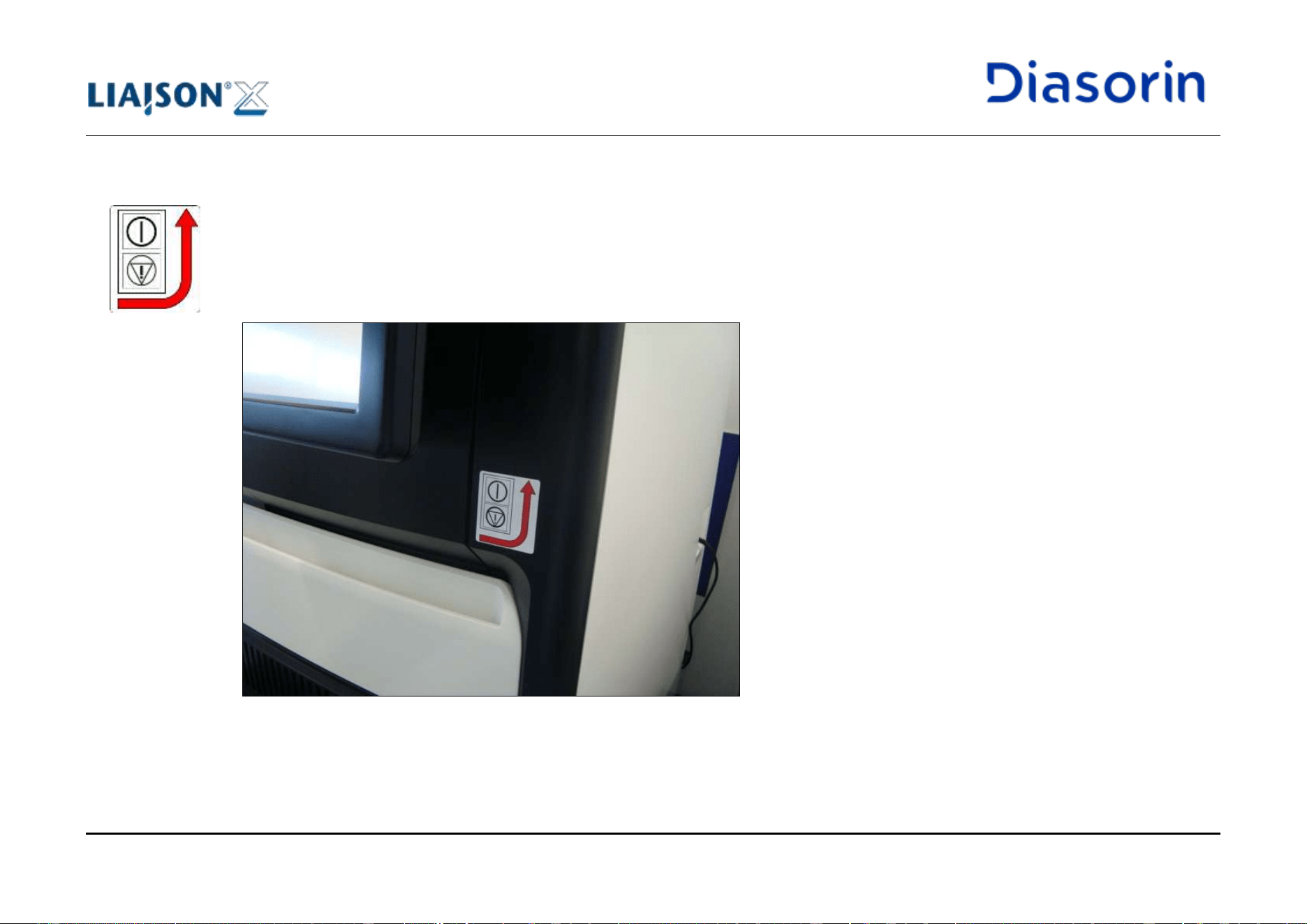
1 Introduction
Page 1-40 LIAISON XL - Instructions for use
Rev. L
1.10.4 Emergency Stop Label
In case of emergency, the Analyzer can be automatically stopped using the main switch available at the right side of the instrument. In order
to inform properly the user about the positioning of the emergency stop, a specific label is placed on the front side of the right blind cover
(Figure 1-4).
Figure 1-4: Emergency stop label
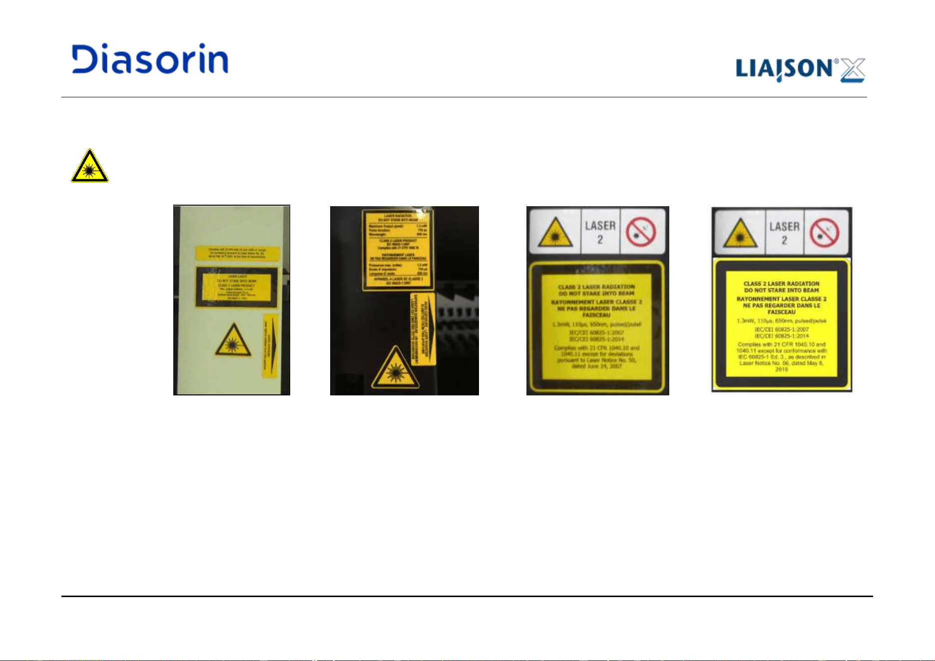
1 Introduction
LIAISON XL - Instructions for use Page 1-41
Rev. L
1.10.5 Laser Hazard Labels
A laser hazard label is positioned on the left side of the sample loading bay (Figure 1-5).
Three different label types are available:
a) First type b) Second type c) Third type d) Fourth type
Figure 1-5: Sample Area labels
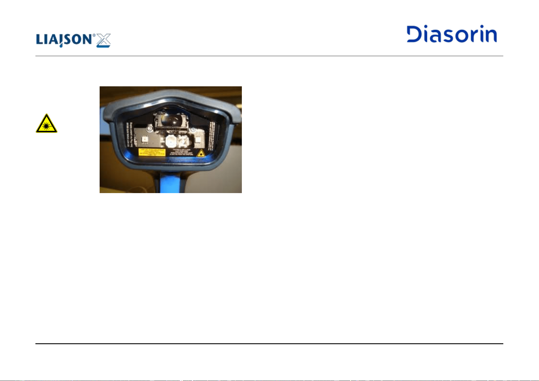
1 Introduction
Page 1-42 LIAISON XL - Instructions for use
Rev. L
Labels placed on the front of the barcode reader (Figure 1-6) inform the users about laser radiation characteristics (see chapter 10.2 of this
document) and dangers (see chapter 1.8.4.1 of this document).
Figure 1-6: Barcode reader labels

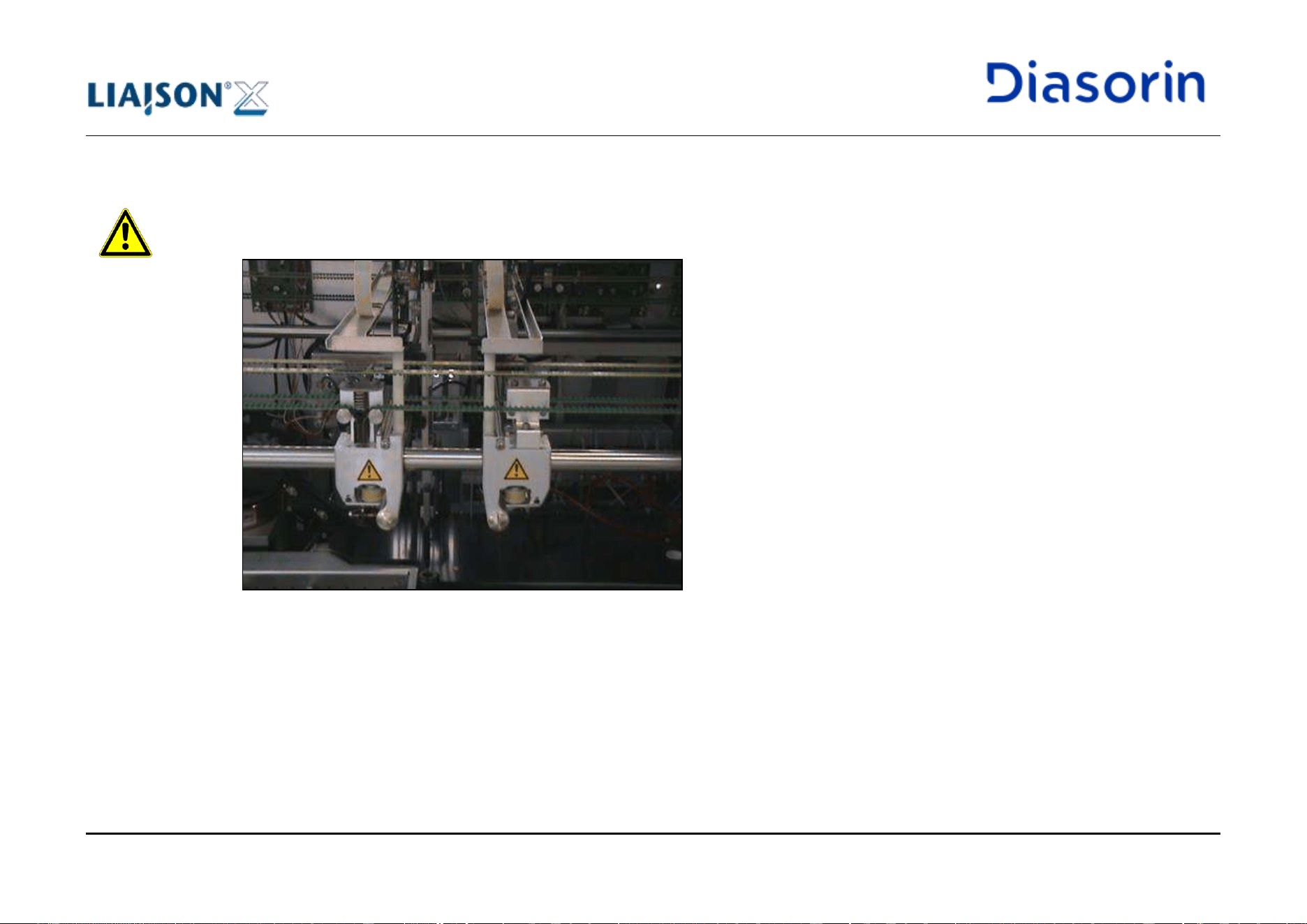
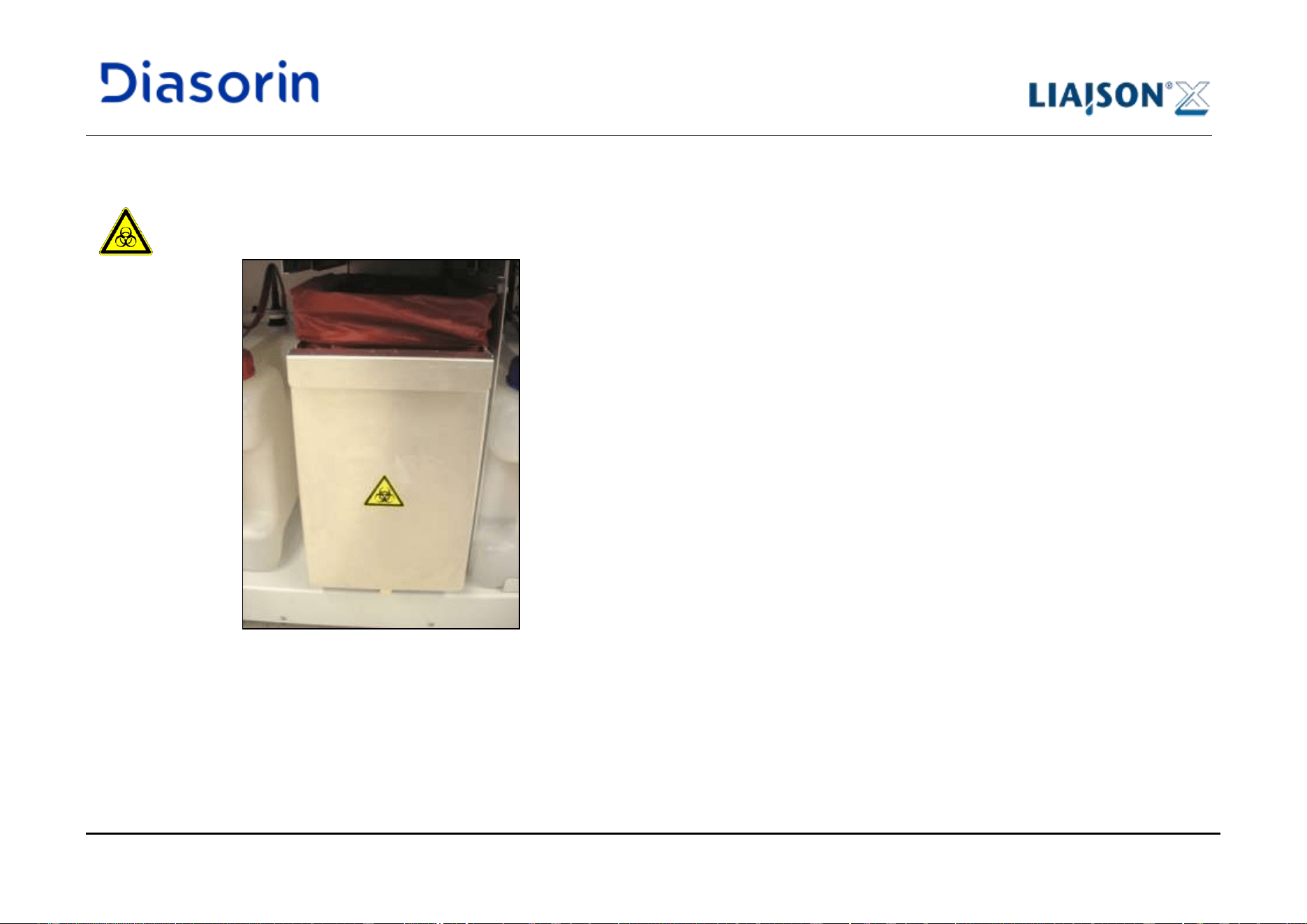
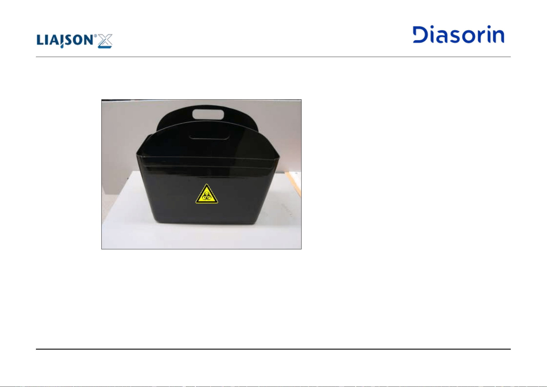
1 Introduction
Page 1-46 LIAISON XL - Instructions for use
Rev. L
The same bio-hazard symbol is also placed on solid waste bags and on both lateral walls of the solid waste bin (Figure 1-10, see also
chapter 4.2.9.8).
All these symbols indicate the users the presence of contaminated materials (tips and cuvettes) inside.
Figure 1-10: Solid Waste Bin label
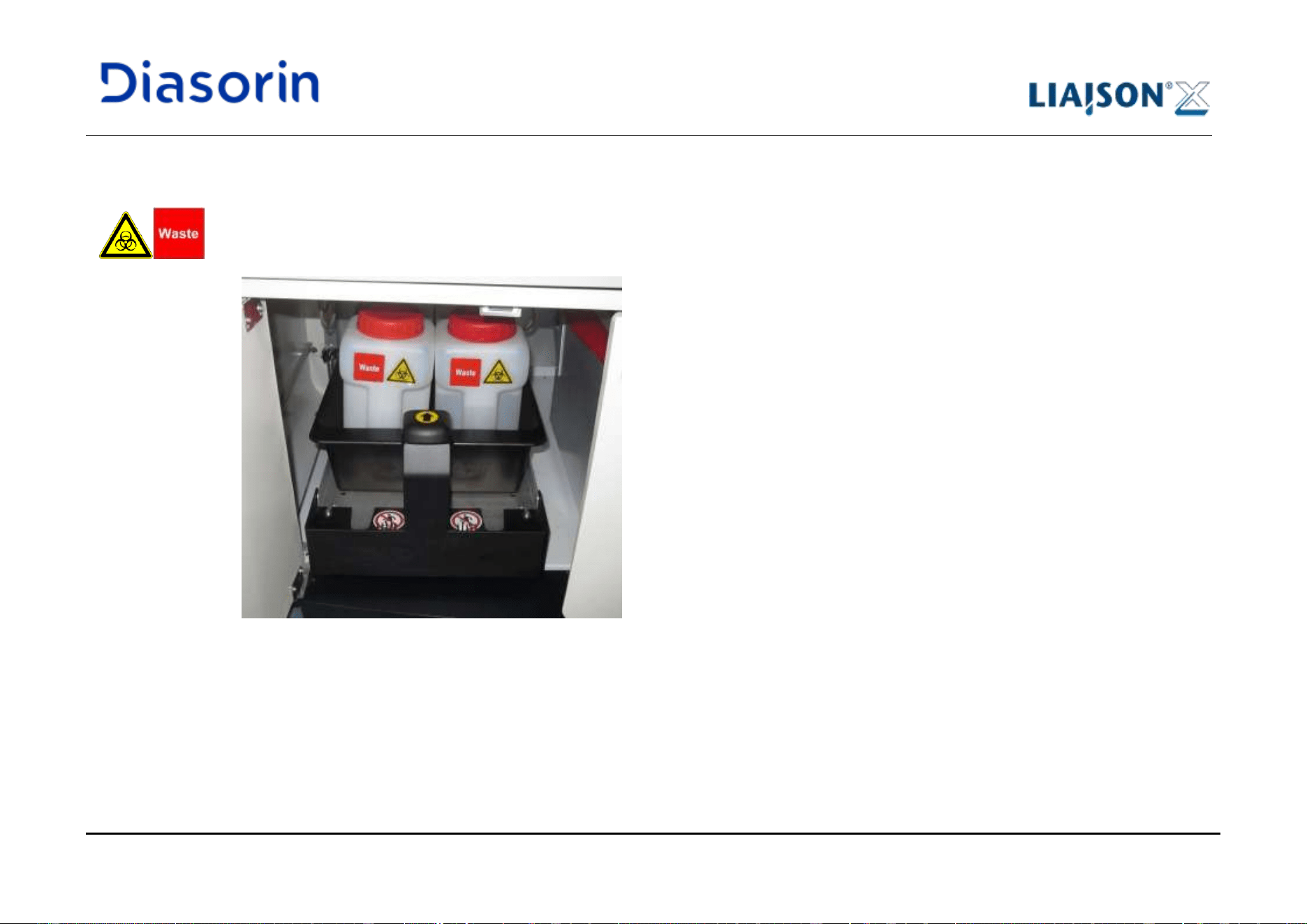
1 Introduction
LIAISON XL - Instructions for use Page 1-47
Rev. L
1.10.9 Liquid Waste Labels
A bio-hazard symbol is placed on the front side of each liquid waste tank (Figure 1-11), together with a label indicating the content.
These symbols indicate the users the presence of contaminated liquids inside.
The same symbols are placed on the floor of the waste basin (see chapter1.10.19).
Figure 1-11: Liquid Waste tank and basin labels
1 Introduction
Page 1-48 LIAISON XL - Instructions for use
Rev. L
1.10.10 Water Label
A symbol, indicating the presence of water inside, is placed on the front side of the water tank and intermediate tank (Figure 1-12).
1.10.11 Wash Label
A symbol, indicating the presence of wash solution inside, is placed on the front side of the wash solution tank and intermediate tank
(Figure 1-12).
A red line indicating the 9 L level is also available on the front side of the tank: this reference helps the user during the preparation of the wash
solution.
For the preparation of the wash solution, refer to the Instruction for Use (IFU) provided with the System Liquid bottles.
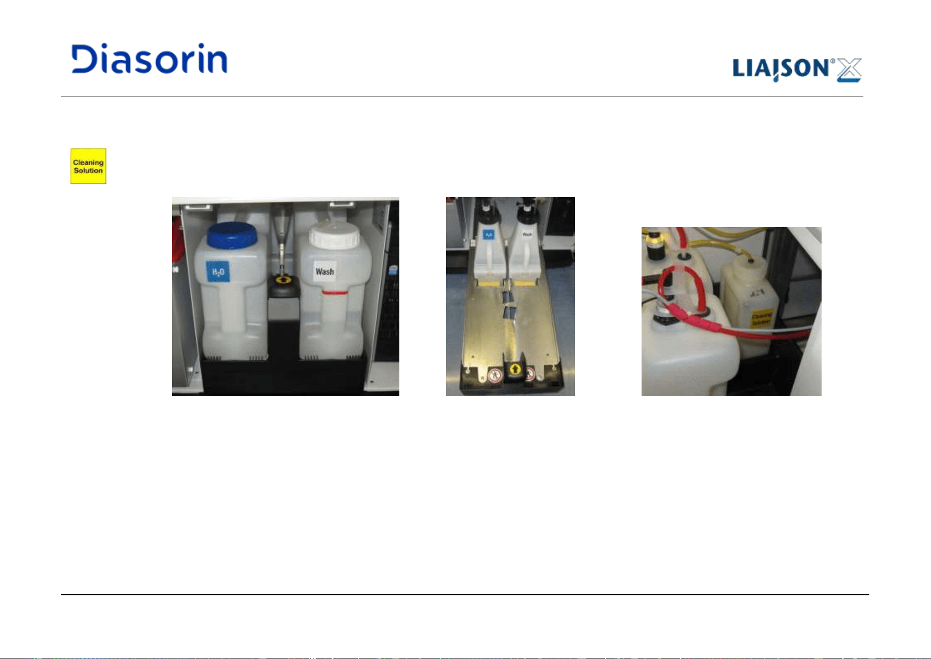
1 Introduction
LIAISON XL - Instructions for use Page 1-49
Rev. L
1.10.12 Cleaning Solution Label
A symbol, indicating the presence of cleaning solution inside, is placed on the front side of the tank (Figure 1-12). In case LIAISON
®
diluteX is
connected to the analyzer, Figure 1-12 is not representative; for further details, please refer to LIAISON
®
diluteX User Manual.
a) Tanks b) Intermediate tanks c) Cleaning Solution tank
Figure 1-12: “Water”, “Wash” and “Cleaning Solution” labels
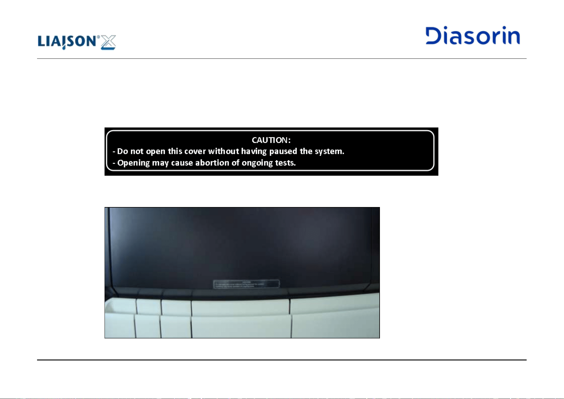
1 Introduction
Page 1-50 LIAISON XL - Instructions for use
Rev. L
1.10.13 “Do not open cover” Label
It is strictly forbidden to open the left top cover of the instrument while the system is running; as a reminder, a label containing this message
(Figure 1-13) is applied to the front of the top cover (Figure 1-14).
The label is available in all different languages supported by LIAISON
®
XL system; during the installation of the system, the field service
engineer takes care of applying to the cover a label in the proper language.
Figure 1-13: “Do not open cover” label – English version
Figure 1-14: “Do not open cover” label positioning
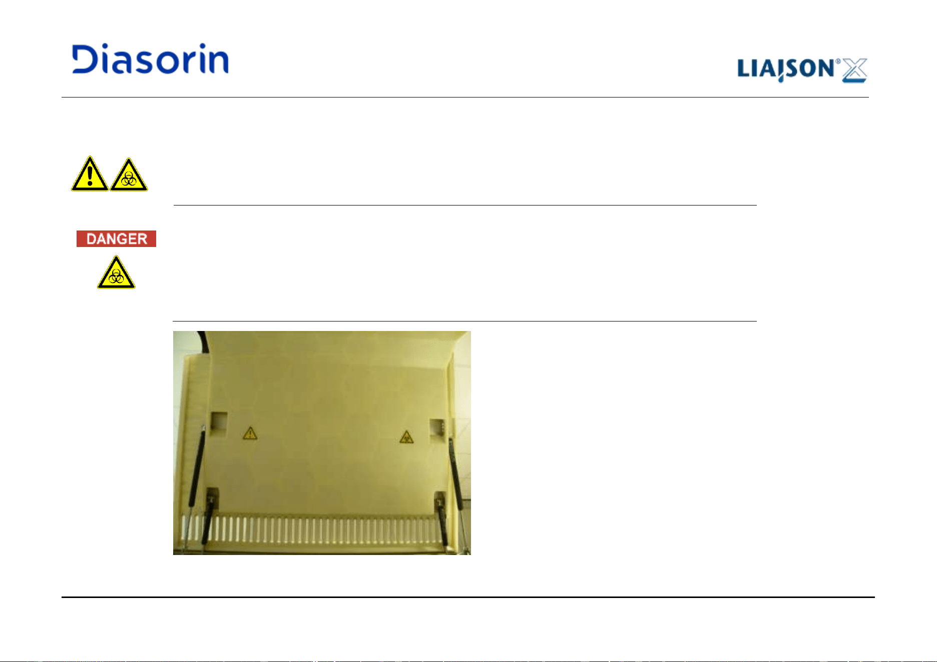
1 Introduction
LIAISON XL - Instructions for use Page 1-51
Rev. L
1.10.14 Top Cover Labels
A caution and a bio-hazard label, informing the user about the possible dangers associated to the contact with the inner parts of the
instrument, are placed on the internal face of the top cover (Figure 1-15).
Risk of infection!
As indicated by the labels applied to the interior face of the left top cover, all internal parts of the system, that are not
defined as user interfaces and for which specific procedures are described, must be treated as being potentially
infectious. For this reason:
• Open the left top cover only if strictly necessary.
• Wear appropriate protection devices (disposable gloves, lab coat, eye protection) before coming into contact with
the internal parts of the system.
Figure 1-15: Top Cover labels
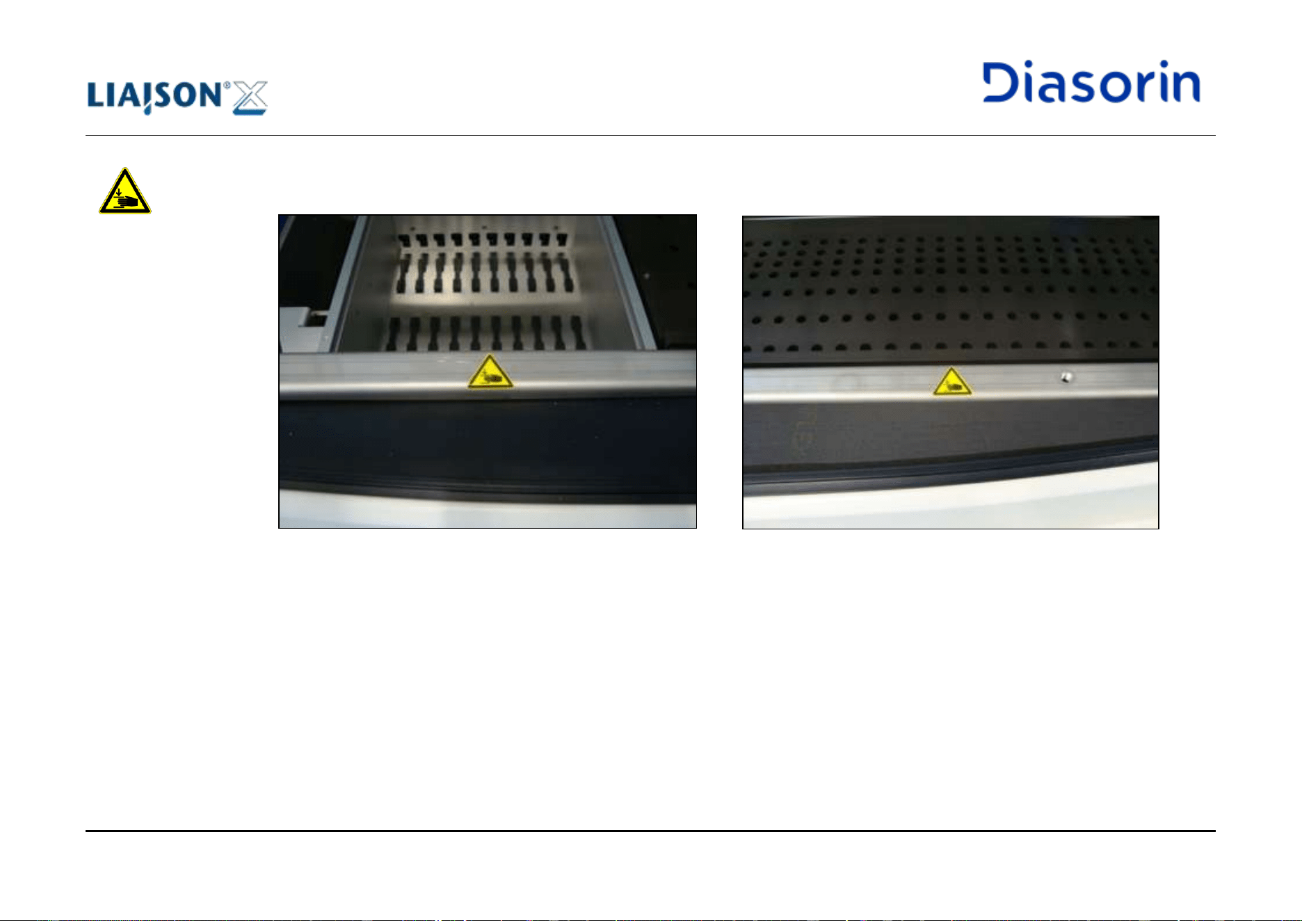
1 Introduction
Page 1-52 LIAISON XL - Instructions for use
Rev. L
In order to prevent possible hand crushings during the opening/ closure of the top covers, two specific warning labels are placed on the
available metal bar, respectively under the left (Figure 1-16.a) and the right (Figure 1-16.b) top covers.
a) b)
Figure 1-16: “Danger of crushing hands” labels
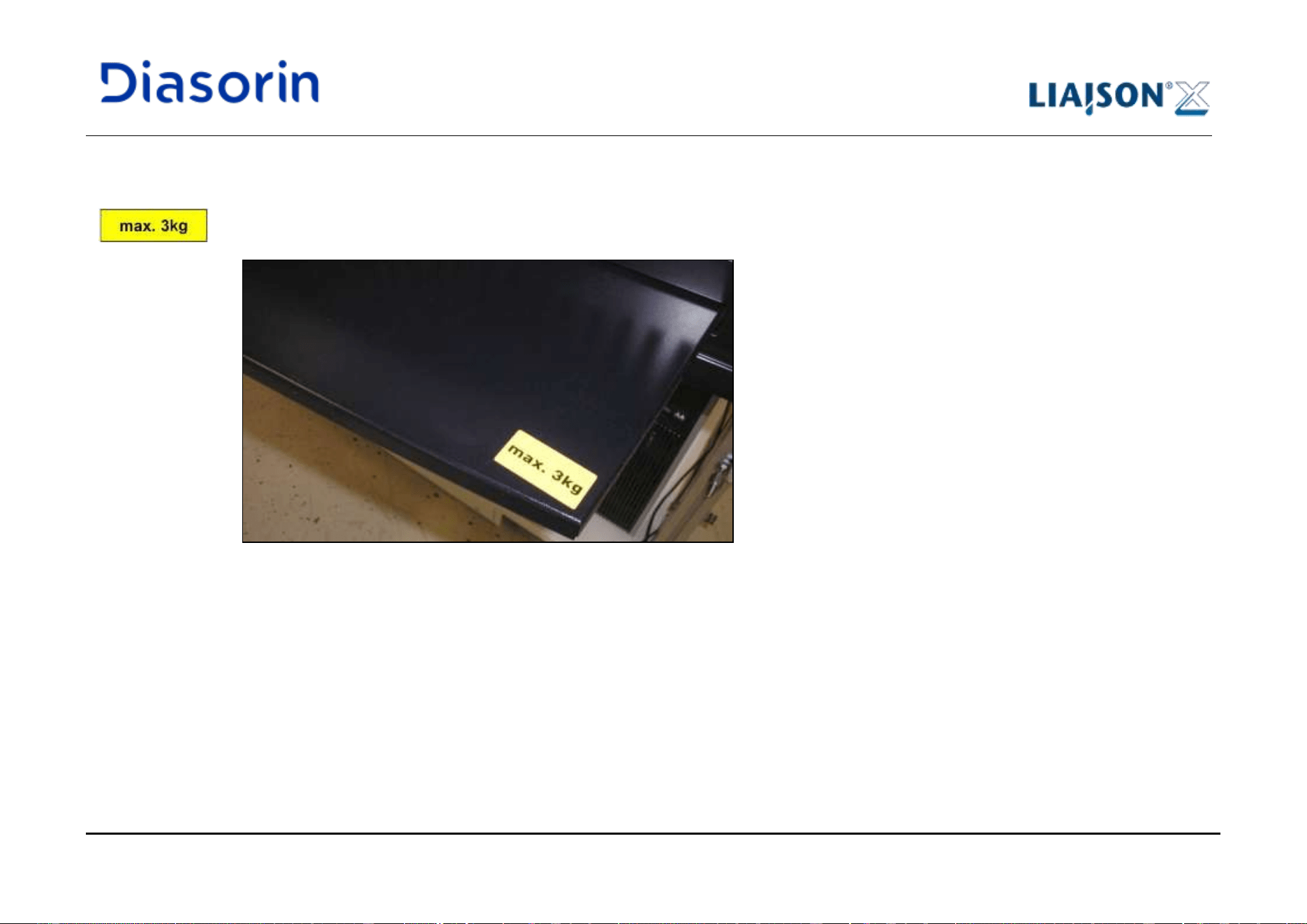
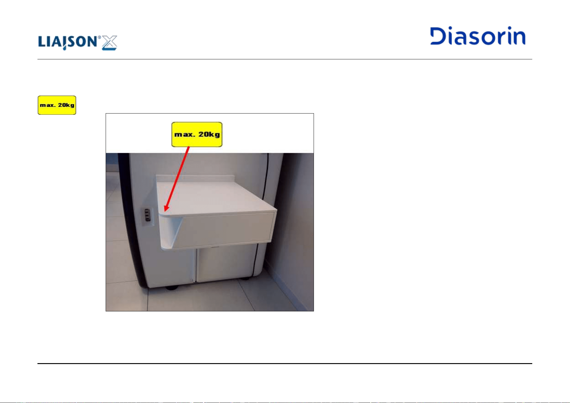
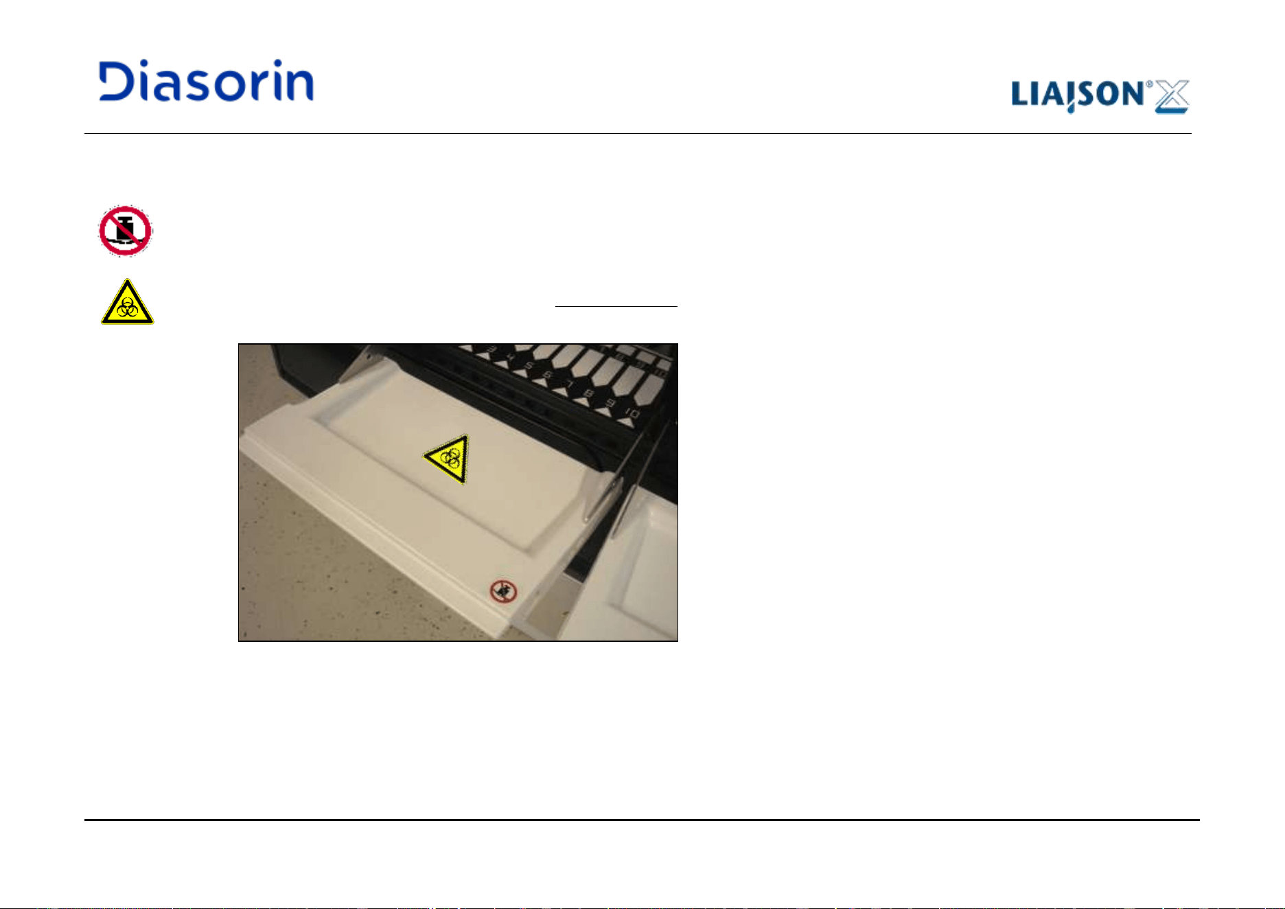
1 Introduction
LIAISON XL - Instructions for use Page 1-55
Rev. L
1.10.17 Flap Labels
No objects shall be put on the flaps of reagent area, sample area and starter area when they are opened. In order to avoid possible
misunderstandings of users, a specific label is applied to the flaps (Figure 1-19, Figure 1-20 and Figure 1-21).
Bio-hazard labels are also applied to the sample and reagent flaps, informing the user to pay attention to the possible presence of spills of
infectious liquids caused by sample or reagent improper handling.
Figure 1-19: Flap labels – Sample Area
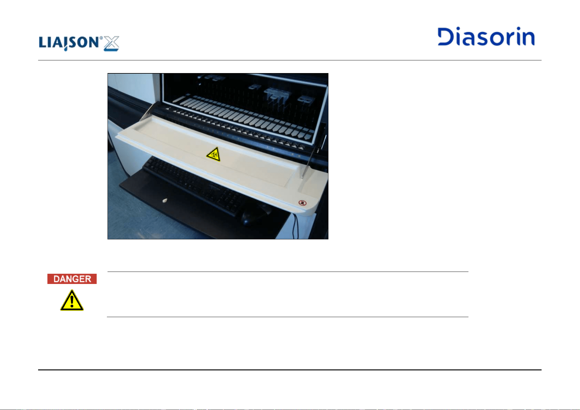
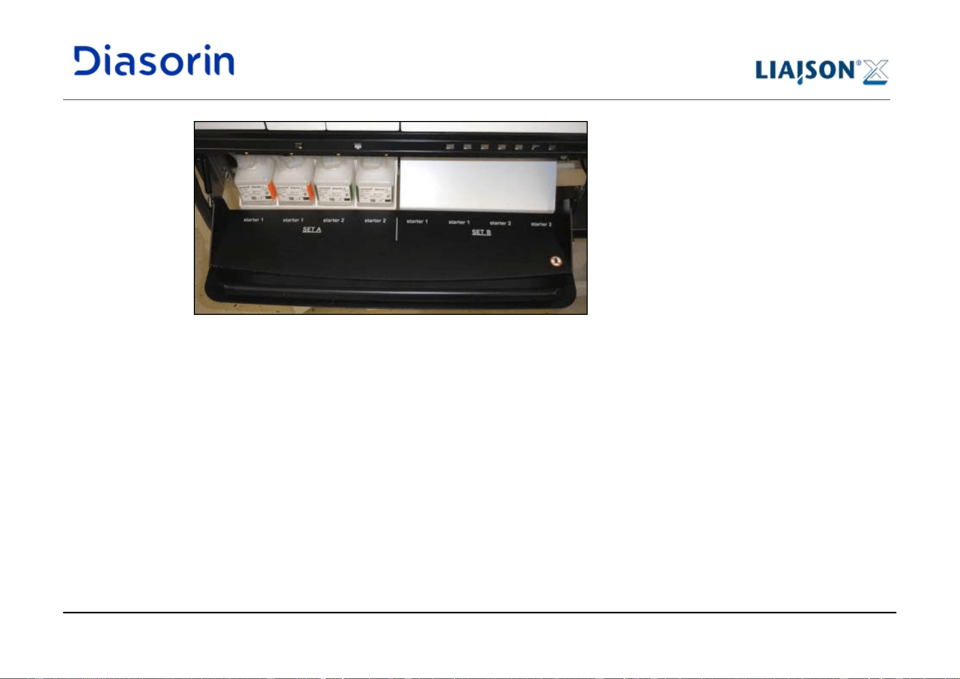
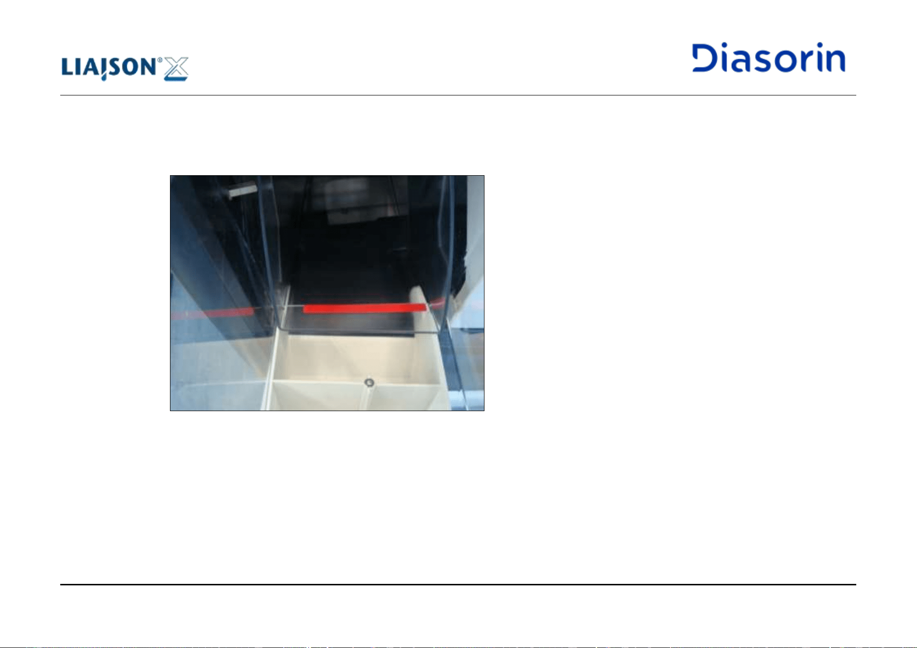
1 Introduction
Page 1-58 LIAISON XL - Instructions for use
Rev. L
1.10.18 Cuvette Reservoir Label
A red line indicating the maximum level of cuvettes that can be loaded without causing mechanical crashes of the system is available on the
cuvette reservoir (Figure 1-22).
Figure 1-22: Cuvette reservoir label
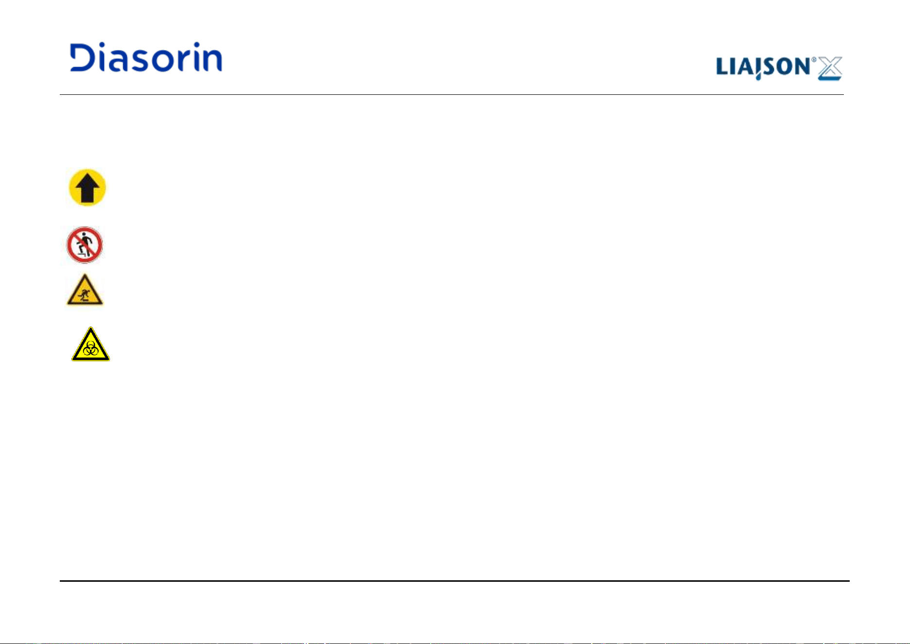
1 Introduction
LIAISON XL - Instructions for use Page 1-59
Rev. L
1.10.19 Cabinet Drawer Labels
The following labelling applies only to instruments with cabinet drawers.
“Close the drawer” label informs the user to always close the drawers once the loading/ unloading of tanks is completed. A label is placed on
the top part of the handle of each drawer (Figure 1-23 and Figure 1-24, ref.a).
“Don’t step” labels inform the user that it is forbidden to step onto the drawers both when the tanks are inserted or extracted. A label is placed
on the floor of each tank slot (Figure 1-23 and Figure 1-24, ref.b).
“Stumble hazard” labels inform the user to pay attention not to fall down when the drawers are out of the cabinet. A label is placed on each
side of each drawer (Figure 1-24, ref.c).
“Bio-hazard” labels inform the user to pay attention to spillage of contaminated liquid in the area of the waste basin occupied by waste tanks.
A label is placed on the slot of each waste tank (Figure 1-23, ref.d).
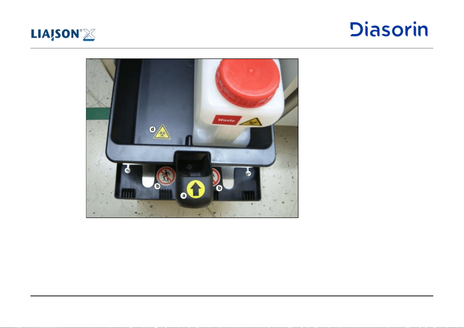

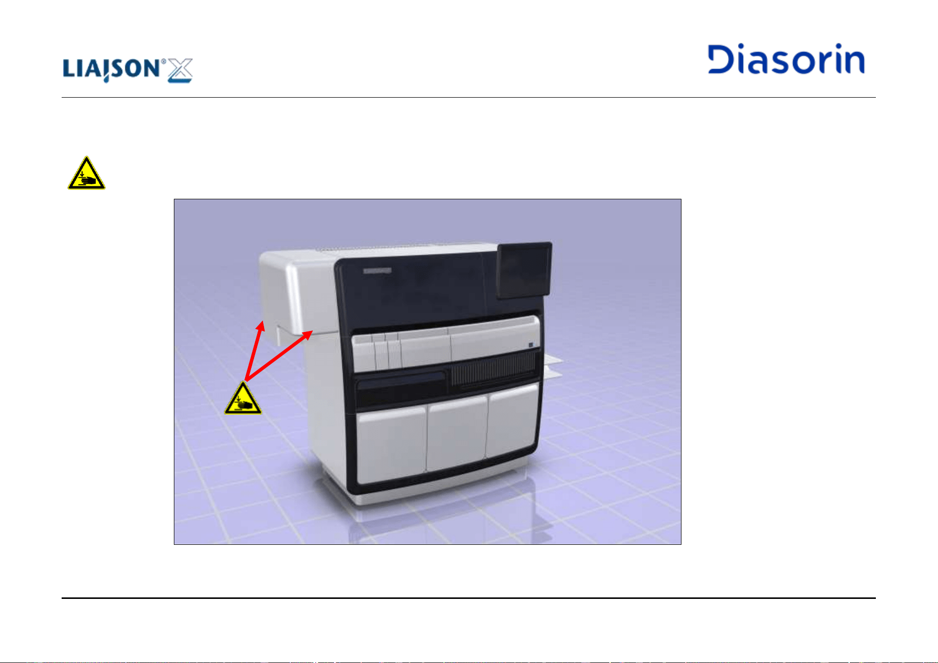
1 Introduction
Page 1-62 LIAISON XL - Instructions for use
Rev. L
1.10.20 Workcell Upgrade Labels
“Danger of crushing hands” labels (Figure 1-25) are placed on the frontside and backside of the workcell upgrade cover, informing the user not
to put hands in the area where the sample arm is moving (see also chapter 4.1.6).
These labels apply only to LIAISON
®
XL with Workcell Upgrade Kit.
Figure 1-25: “Danger of crushing hands” labels for LIAISON
®
XL with Workcell Upgrade Kit
1 Introduction
LIAISON XL - Instructions for use Page 1-63
Rev. L
1.11 Operational Precautions and limitations
This section describes the operational requirements, precautions, and limitations to ensure user safety and accurate assay results.
User must follow these requirements to help ensure proper system performance.
Not following the requirements and precautions provided can impact the system and assay performance and may cause damage to the
system or adversely affect assay results.
1.11.1 General requirements
• Ensure the system is out of direct sunlight, heat and drafts, and away from any heat generating device. Exposure to heat and drafts can
interfere with the ability of the system to maintain an operating temperature that is within the acceptable range.
• Maintain the required space on all sides of the system. For more information about space requirements, see chapter 10.5. This space
buffer is essential for:
o Accurate temperature control of the system;
o Adequate cooling of electrical components;
o Easy access for disconnecting the power cord when required;
o Easy access for maintenance.
Danger due to Overheating
Improper positioning (installation or operation) of the system or improper environment may cause fire or serious
system damage in case of overheating.
• Leave the system power on continuously unless instructed otherwise in a maintenance or troubleshooting procedure, or unless an
emergency situation occurs.
• Perform maintenance procedures as recommended in chapter 8.
• Do not attempt any maintenance that is not specified in the documentation provided by DiaSorin Italia S.p.A.
• In case of user injury, keep the potential contaminant agent for a subsequent analysis.
1 Introduction
Page 1-64 LIAISON XL - Instructions for use
Rev. L
1.11.2 Forbidden foreseeable misuse
The following list includes (but is not exhaustive) a set of forbidden foreseeable misuses identified by the Manufacturer. The user must
carefully read below notes and follow the indicated safe way to operate to avoid risk of harm.
• Troubleshooting operations to resolve cuvette jamming performed while moving parts are active. Intended use: operation is allowed when
moving parts are inactive.
• Introduce body parts in the hazard area while the Analyzer is active with moving parts. Intended use: any needed operation is allowed
when moving parts are inactive.
• Operate the Analyzer without the solid waste bag and container onboard unless during waste bag replacement. Intended use: waste bag
and its container must be onboard unless during waste bag replacement.
• Operate the Analyzer with no liquid waste tank connected. Intended use: a liquid waste tank must always be connected before operating.
This restriction is not applicable if waste tubing is directly connected to a laboratory drain.
1.11.3 System operation
1.11.3.1 Precautions and Requirements before operation
Before beginning to operate the system, the user has to:
• Read this manual thoroughly to understand full functionality of the system and associated hazards.
• Read the sections of the reagent manufacturer's assay-specific documentation that are associated with:
o Warnings and precautions;
o Safety precautions.
• Verify that the solid waste container is equipped with the appropriate bag.
• Verify that the liquid waste containers are not full and correctly positioned.
1 Introduction
LIAISON XL - Instructions for use Page 1-65
Rev. L
1.11.3.2 Precautions during operation
• Keep all drawers and covers closed if not unless instructed otherwise in a described procedure.
• Do not disconnect any electrical connection while the power is on.
• Respond to system warnings during processing.
• Dispose of all waste material according to local regulations.
• Remove all samples and integrals from the system in case of an emergency stop.
1.11.4 Handling of reagents and consumables
See the manufacturer's assay-specific documentation (such as a package insert), the specific product label, the appendixes of the present
manual or the Material Safety Data Sheet (MSDS) for detailed information, including hazard symbols.
1.11.5 Handling of specimens
Carefully read the reagent manufacturer's assay-specific documentation and the chapter 5.6.1 of the present manual for information about
specimen collection, preparation, and storage.
Consider all system surfaces or components that have been in contact with human-sourced materials as potentially infectious.
1 Introduction
Page 1-66 LIAISON XL - Instructions for use
Rev. L
1.11.6 Limitation of result interpretation
Any assay result supplied by the Analyzer does not aim to be released as medical advice or service without approval by authorized medical
personnel.
Assay results must be used with other clinical data such as patient symptoms, other test results, patient history, clinical data, information
available from clinical evaluation, and other diagnostic procedures.
The LIAISON
®
XL has been validated for its intended use only. However, errors can occur due to potential operator errors and LIAISON
®
XL
System technology limitations. If assay results are inconsistent with clinical evidence, additional testing is suggested to confirm the result.
Clot Detection System
Notwithstanding the Analyzer is equipped with a clot detection system, the user is not authorized by DiaSorin to load
consciously on the Analyzer sample tubes containing clots. Any default of the system related to a relevant
unappropriate use is in the sole responsibility of the user.
1.12 Installation of the System
Installation
Please note that the LIAISON
®
XL system may only be installed by authorized service personnel.
The Analyzer is not designed and constructed to be operated in a potentially explosive atmosphere. The Analyzer
must not be installed and used in a laboratory with potentially explosive atmosphere.
Customer is responsible to assess that the above requirement is respected before allowing DiaSorin Italia S.p.A. or
its affiliates installing the Analyzer.
1 Introduction
LIAISON XL - Instructions for use Page 1-67
Rev. L
Note Technical Data
See chapter "Technical Data" (see chapter 10) for power requirements, computer and connections, installation
dimensions, weight and environmental conditions.
After the installation, the user of the LIAISON
®
XL system receives an installation qualification which documents the
proper installation of the LIAISON
®
XL system.
1.13 Removal of the System
If the system must be shipped to a new location, user shall contact the local DiaSorin field service representative for assistance.
Removal
The removal of the LIAISON
®
XL system must be performed by authorized service personnel.
Reinstallation
If the LIAISON
®
XL system moves within the plant, the authorized service personnel must perform a complete
reinstallation. If this reinstallation is omitted, this can cause damage of the system or irregular pipetting performance.
2 PC security measures
LIAISON XL - Instructions for use Page 2-1
Rev. L
2 PC security measures
2.1 Introduction
LIAISON
®
XL software is intended to be used in a controlled environment. Access is allowed only to trained and authorized users.
Nevertheless, usage of the system may undergo the risk of unauthorized access, leading to possible data loss, corruption or unauthorized
distribution.
Furthermore, updates to the software modules provided with the system (e.g. Operating System) must be distributed under controlled process,
to ensure that the system still behaves according to its intended use after the update.
This chapter describes the policy followed by DiaSorin and partners regarding how software elements are kept updated on systems installed
in end-user environment.
2.2 Unauthorized Local Access
2.2.1 Potential issues
Usage of the system is supposed only to trained and authorized users, who are supposed to follow the intended use of the system.
Unauthorized users could access or damage a computer system without the owner's informed consent. Consequences may be software and
data loss, corruption or unauthorized distribution.
2 PC security measures
Page 2-2 LIAISON XL - Instructions for use
Rev. L
2.2.2 Protection measures
Access to the LIAISON
®
XL software is based on an access rights structure that allows system operation only to authorized users:
• operating the system, including access to any data, is only possible when typing a user identifier (made of “user name” and
“password”), that is unique for each end-user;
• “user name” is unique and cannot be re-assigned;
• both “user name” and “password” must be at least 8 characters long; the system allows to enforce use of complexity and history
requirements (newly created passwords shall bear at least one upper case, one lower case, one number, one special character and
shall differ from the last five used ones);
• for each “user name”, a “password duration” can be set; within the time frame based on “password duration”, the system will force the
user to change the “password” ;
• each user can change his/her own password;
• since, during installation of the system, for every user one default "password" will be inserted. it will be in the care of DiaSorin and
partners personnel to inform the end-users to modify her/his password at the first usage;
• it’s possible to define a “session expiration time”, i.e. a time interval after which the system logs-off the current user;
• end-users are logged into Operating System with a restricted account;
• end-users have no means to overcome the LIAISON
®
XL software application, i.e. they have no access to the Operating System and
other applications.
• an anti brute force mechanism can be enabled to prevent that not authorized people may gain access by guessing username and
password by means of multiple consecutive attempts. Contact the local service support to enable it.
2 PC security measures
LIAISON XL - Instructions for use Page 2-3
Rev. L
2.3 Malware
2.3.1 Potential issues
Usage of LIAISON
®
XL computer could lead to voluntary or involuntary introduction of malicious software, like virus, worms, spywares.
This malicious software (also called malware) is designed to infiltrate or damage a computer system without the owner's informed consent.
Consequences may be software and data loss, corruption or unauthorized distribution.
The introduction of such malicious software may occur:
• via network;
• via a local USB device;
• via a local CD-Rom.
2.3.2 Protection measures
The state-of-art, worldwide spread approach is to provide a network firewall, a personal firewall and an integrated protection tool, generically
called antimalware. This approach looks not adequate for the LIAISON
®
XL computer for several reasons:
• the network firewall should be installed by network administrators, who in this case are end-users in regards to DiaSorin, therefore
DiaSorin has no control on the network firewall in terms of adequateness and update frequency;
• an antimalware must be kept up-to-date to be efficient, therefore almost daily updates are necessary; the sole mode to perform
frequent updates is to connect the computer to the internet, but:
o it cannot be ensured that all computers are connected to the internet, and also for those connected the connection cannot be
guaranteed upfront, while a malware can be introduced in any moment, even without internet connection;
o furthermore, a daily update of the antimalware would necessary mean that the updates are managed directly by antimalware
producer; therefore, the system configuration would be frequently updated, while DiaSorin could not guarantee a continuous
validation update in such continuously changing configuration; for example, an antivirus could unexpectedly recognize as
malware and delete files, that are necessary part of the validated environment, with the consequence of potential
malfunctioning of the software.
2 PC security measures
Page 2-4 LIAISON XL - Instructions for use
Rev. L
For all these reasons, an alternative integrated approach has been chosen:
• all the Operating System service and ports, that are not strictly required for the validated applications, will be blocked on the computer;
• the Operating System integrated firewall is activated, and configured such that all remote access to the system is denied
(excluding single specific ports needed for remote access authorized by DiaSorin);
• on the Operating System, the AutoRun for all USB storage devices will be disabled;
• it is prohibited to install any CD-Rom or Floppy Disk USB device;
• importing infected files from USB devices or CD-Rom is prevented by design, as end-users will have access on the computer to the
sole features allowed by the LIAISON
®
XL, i.e. will not have access to the Operating System features, and LIAISON
®
XL will allow to
import only files with specific proprietary extensions, disregarding any file with different extension;
• as additional protection, a specific and defined antimalware is installed on Liaison XL, mainly counting on its heuristic detection
methods. No other antimalware can be installed on Liaison XL.
2.4 Unauthorized access via network
2.4.1 Potential issues
A LIAISON
®
XL computer connected to a network could be accessed by unauthorized persons, causing unpredictable effects on installed
software and data. Consequences may be software and data loss, corruption or unauthorized distribution.
2.4.2 Protection measures
A personal firewall is an application which controls network traffic to and from a computer, permitting or denying communications based on a
security policy.
The Operating System integrated firewall is activated, to ensure incoming access from a remote station is denied.
Theoretically, only computers connected to a network require a personal firewall, but for the sake of uniformity all computers provided with
Liaison XL will be protected with the Operating System personal firewall.
2 PC security measures
LIAISON XL - Instructions for use Page 2-5
Rev. L
2.5 System update
2.5.1 Potential issues
The Operating System and the other software modules installed on LIAISON
®
XL computer may require to be updated from time to time, in
order to fix the discovered issues. Typically these are network vulnerabilities.
2.5.2 Protection measures
Introducing continuous changes into the software modules introduces also a connected technical risk: the more changes are introduced, and
the more frequently they are, the more risks would accumulate in these regards. The described protection measures against external
intrusions is considered safe enough to face the known risks on the LIAISON
®
XL computer, that is strictly controlled and shielded even if
vulnerabilities would be discovered.
For these reasons, the Operating System and the other software modules installed on LIAISON
®
XL computer will be updated only if such
change is due to known technical reasons.
2.6 Local/network printing
2.6.1 Potential issues
There are two possible printing device types that can be used (only one per system):
• a local printer;
• a network printer.
The usage of a local printer, installed by DiaSorin on LIAISON
®
XL systems as “default printer”, requires installing printer drivers that could
affect the system with consequences like software and data loss.
The usage of a network printer, configured by DiaSorin on LIAISON
®
XL systems as “default printer”, requires to install printer drivers, that
may be not available for the LIAISON
®
XL computer, or to rely on Operating System printing service, that could affect the system with
consequences like software and data loss.
2 PC security measures
Page 2-6 LIAISON XL - Instructions for use
Rev. L
2.6.2 Protection measures
The local printer models, installed by DiaSorin on LIAISON
®
XL systems, are validated against their intended use. No printers that did not
pass the validation test will be installed on LIAISON
®
XL systems.
The usage of a network printer will be supported:
• By installing printer drivers, provided that a printer model validation is carried out
o through the definition of a predefined set of “standard printer models”
o via dedicated validation for any additional printer model
• or relying on the Operating System printing service, without installing printer drivers
2.7 Remote access
2.7.1 Potential issues
LIAISON
®
XL systems may be connected to servers used by DiaSorin for the purpose of troubleshooting, customer support, device monitoring
and software update. This will be managed through a dedicated applications that may require software installation on both LIAISON
®
XL
computer and field personnel computers.
The availability of connection, may vary depending on countries and specific user technical infrastructure.
Presence of such application could be lead to systems remotely accessed by unauthorized persons, causing unpredictable effects on installed
software and data. These situations could lead to consequences such as software and data loss, corruption or unauthorized distribution.
2.7.2 Protection measures
The remote connection will be hosted on a communication channel that undergoes cryptography. This prevents unauthorized users from
observing the channel.
DiaSorin guarantees that only authorized personnel are allowed to perform remote connection.
DiaSorin adopts a risk based approach to implement adequate technical measures aimed at reducing risk of the described potential issues.
2 PC security measures
LIAISON XL - Instructions for use Page 2-7
Rev. L
2.8 Privacy
2.8.1 Potential issues
LIAISON
®
XL produces analytical results that refer to the health condition of patients.
Therefore, a potential risk of spreading health patient data may exist in regards to:
A. DiaSorin personnel (directly or indirectly involved in technical activities on the laboratory systems)
B. DiaSorin partners personnel (directly or indirectly involved in technical activities on the laboratory systems)
C. DiaSorin suppliers personnel (indirectly involved in technical activities on the laboratory systems)
Patient health data could be potentially available to the above mentioned personnel in the following situations:
1. during a technical intervention on laboratory systems, personnel of type “A” or “B” may need to access the LIAISON
®
XL software that
may contain patient health data, therefore check such data on the screen or print data as hard copy;
2. personnel of type “A”, “B” or “C” could retrieve patient health data as part of data exchanged in electronic or paper format, as part of
technical troubleshooting or maintenance activities that involve such personnel.
Furthermore, users different from above listed types could get in contact with patient health data.
Specific country regulations may require different means to overcome the listed potential issues.
2.8.2 Protection measures
The following measures are adopted in order to make the system compatible with the known regulatory requirements. Measures, that are
already listed and described in the present chapter and are in place to protect the patient health data, are not repeated here.
1. Both the patient health data and the demographics are encrypted;
2. If the patient health data have been exchanged on electronic format, this will happen through a encrypted channel;
3. It is possible to manually perform a complete back-up of patient health data;
4. It is possible to schedule automated back-up of patient health data;
5. Sample identifier (SID) as well as patient identifier (PID), are conceived as an anonymous sequence of alphanumeric characters, that
the end-users may use in combination with their laboratory system, in which all the patient information are maintained, and particularly
the patient demographics;
2 PC security measures
Page 2-8 LIAISON XL - Instructions for use
Rev. L
6. The system can perform all the analyses without the need to insert the patient demographics; as such it is recommended that
demographic insertion is avoided both as manual input and LIS transmission;
7. The system allows to fill the fields "name" and "last name" present in the patient information;
8. In case the fields "name" and "last name" (patient demographics) are filled:
a. the access to such data will be restricted on the system to specific users, for whom the laboratory responsible people will ask
for activation (during system installation);
b. such measure regards the display on screen and the printed hard copies of such information, either directly from the Personal
Computer connected to the system, or from any other Personal Computer on which the LIAISON
®
XL software is installed,
to which the data bases are loaded after exporting from the system Personal Computer;
c. such measure covers both the direct visualization of information (e.g. the reading on screen of health data in combination with
demographics), and indirect search (e.g. the possibility to go back from health data to the SID and from the SID to the
personal data);
d. therefore, not explicitely authorized users will not have the rights to get access to patient demographics, not even in case the
user provided the database containing patient demographics.
As it regards the responsibilities of end-users, where local regulations require so, the end-user is responsible for the following behavior:
on LIAISON
®
XL SID and PID must not refer to the patient; such traceability shall be kept on the laboratory tracing systems.
In regards to the responsibilities of DiaSorin, where local regulations require so, DiaSorin responsibility is configured as follows:
a. DiaSorin will solicit the respect of the applicable privacy regulations, if there should be evidence that a LIAISON
®
XL is used without
compliance to the rules stated by applicable privacy regulations;
b. DiaSorin is not liable for improper use of data generated through the LIAISON
®
XL once data is outside of the boundaries of the
system itself, i.e. after data has been written, printed, or sent in electronic format to other laboratory systems.
2 PC security measures
LIAISON XL - Instructions for use Page 2-9
Rev. L
2.9 Security Requirements for Operating Environment
The Operating Environment is defined as the complex of physical and logical/IT environment interacting with the LIAISON
®
XL during intended
operating conditions.
To integrate the LIAISON
®
XL in the Operating Environment according to security standards and best practices, the Operating Environment
shall comply with the following:
1. Applicable data privacy regulations;
2. Adequate security controls including network traffic;
3. Any patch management process shall prevent interoperability/compatibility issues with the LIAISON
®
XL.
3 Measuring Principle of the LIAISON
®
XL Immunoassays
LIAISON XL - Instructions for use Page 3-1
Rev. L
3 Measuring Principle of the LIAISON
®
XL
Immunoassays
3.1 Explanations for Steps of Assays
Assays (also defined as “tests”) that run on the LIAISON
®
XL are divided into major categories:
• 1-step assays
• 2-step assays
• 3-step assays
The numbered steps refer to the required amount of incubation sequences for a test. An incubation sequence is described as the amount of
times a sample must enter the incubator during the run.
These categories are described in detail below.
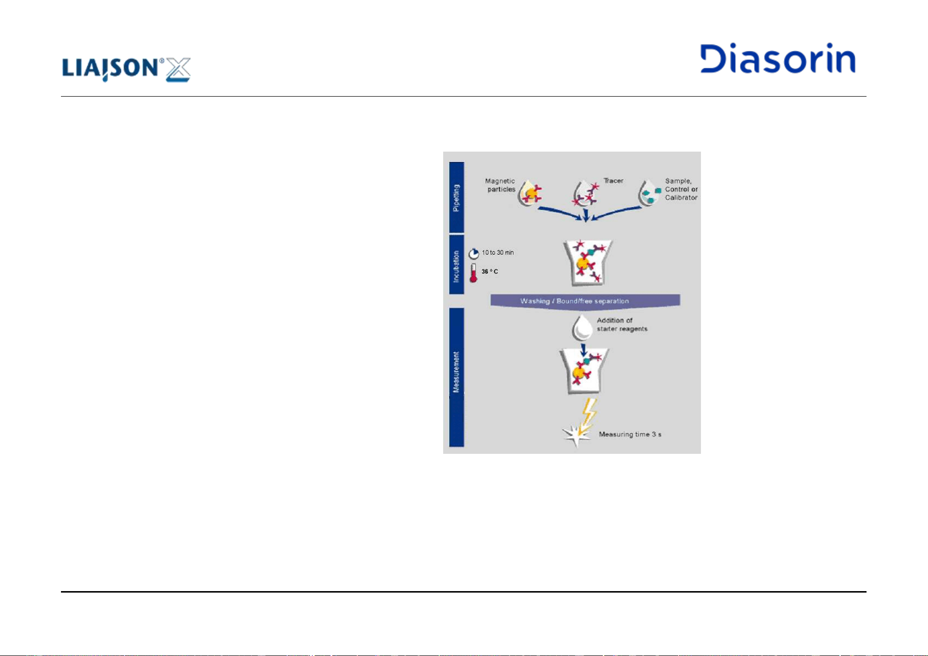
3 Measuring Principle of the LIAISON
®
XL Immunoassays
Page 3-2 LIAISON XL - Instructions for use
Rev. L
3.1.1 Test Procedure 1-Step Assay
A 1-step assay refers to a test or assay that has:
• 1 incubation sequence (the time of incubation
may range depending on the assay).
• 1 wash sequence (the amount of washing for
this sequence is assay dependent).
Most assays that are 1-step have an incubation
time of 10 minutes. The figure below is only an
example. Pipetting sequences are also assay
dependent.
Figure 3-1: Example of test procedure “1-step assay”
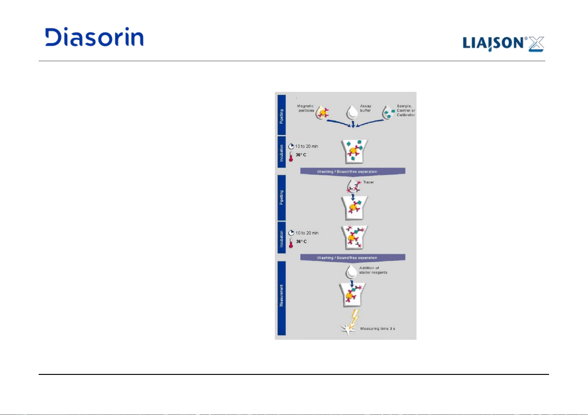
3 Measuring Principle of the LIAISON
®
XL Immunoassays
LIAISON XL - Instructions for use Page 3-3
Rev. L
3.1.2 Test Procedure 2-Step Assay
A 2-step assay refers to an assay that has:
• 2 incubation sequences (the time of incubation
may range depending on the assay).
• 1 or 2 wash sequences (the amount of
washing for each sequence is assay
dependent).
Most assays that are 2-step have an incubation
time of 10 minutes each. The figure below is only
an example. Pipetting sequences are also assay
dependent.
Figure 3-2: Examples of test procedure “2-step assay”
3 Measuring Principle of the LIAISON
®
XL Immunoassays
Page 3-4 LIAISON XL - Instructions for use
Rev. L
3.1.3 Test Procedure 3-Step Assay
A 3-step assay refers to an assay that has:
• 3 incubation sequences (the time of incubation may range depending on the assay).
• 1 to 3 wash sequences (the amount of washing for each sequence is assay dependent).
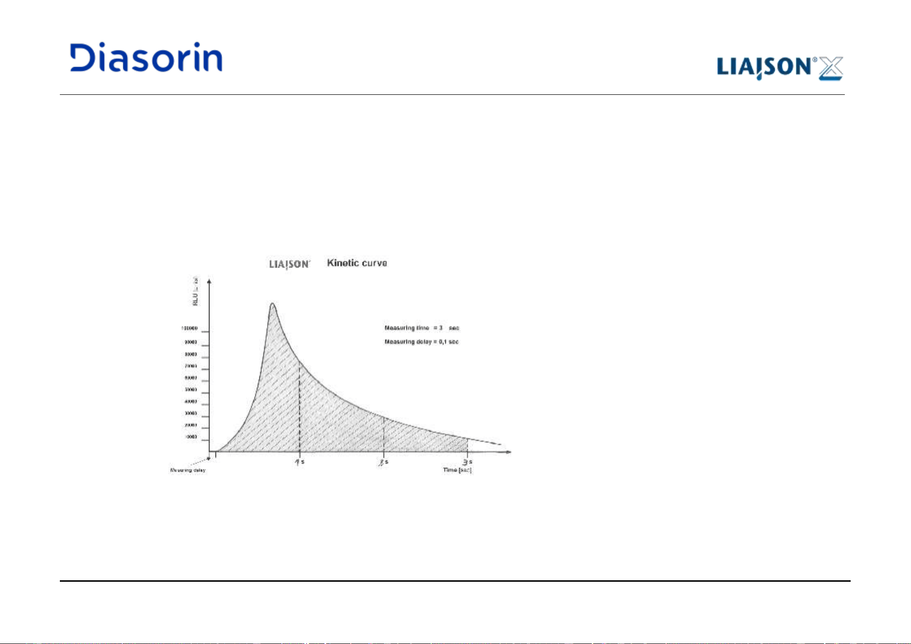
3 Measuring Principle of the LIAISON
®
XL Immunoassays
LIAISON XL - Instructions for use Page 3-5
Rev. L
3.2 Measuring Principle
• After the last wash cycle has been completed, the cuvette is transported into the Reader.
• When the cuvette reaches the position under the injection head, starter reagent 1 will be injected.
• After an appropriate pump delay time (2.55 sec minimum) the starter reagent 2 will be injected into the cuvette to start the
chemiluminescence reaction.
• After the measuring delay time of 0.1 sec, the measuring signal is obtained and integrated over the measuring period (3.0 sec for most
assays).
Figure 3-3: LIAISON
®
XL kinetic curve
3 Measuring Principle of the LIAISON
®
XL Immunoassays
Page 3-6 LIAISON XL - Instructions for use
Rev. L
3.3 Measuring Function Description
• The chemically emitted light is measured by a selected highsensitive, low-noise photomultiplier [PMT]. The linear measuring range of the
photomultiplier is 300 – 650 nm. The light peak of the chemiluminescence is emitted at a wavelength of 420 nm.
• The PMT is operating as an ultra-fast photon counter. The pulses are amplified by a rapid electronic amplifier. A circuit, which suppresses
the PMT signal-noise is also implemented in the PMT box.
• Not the number of counts, but the Relative Light Units [RLU] are used as units of the measurement for the raw data.
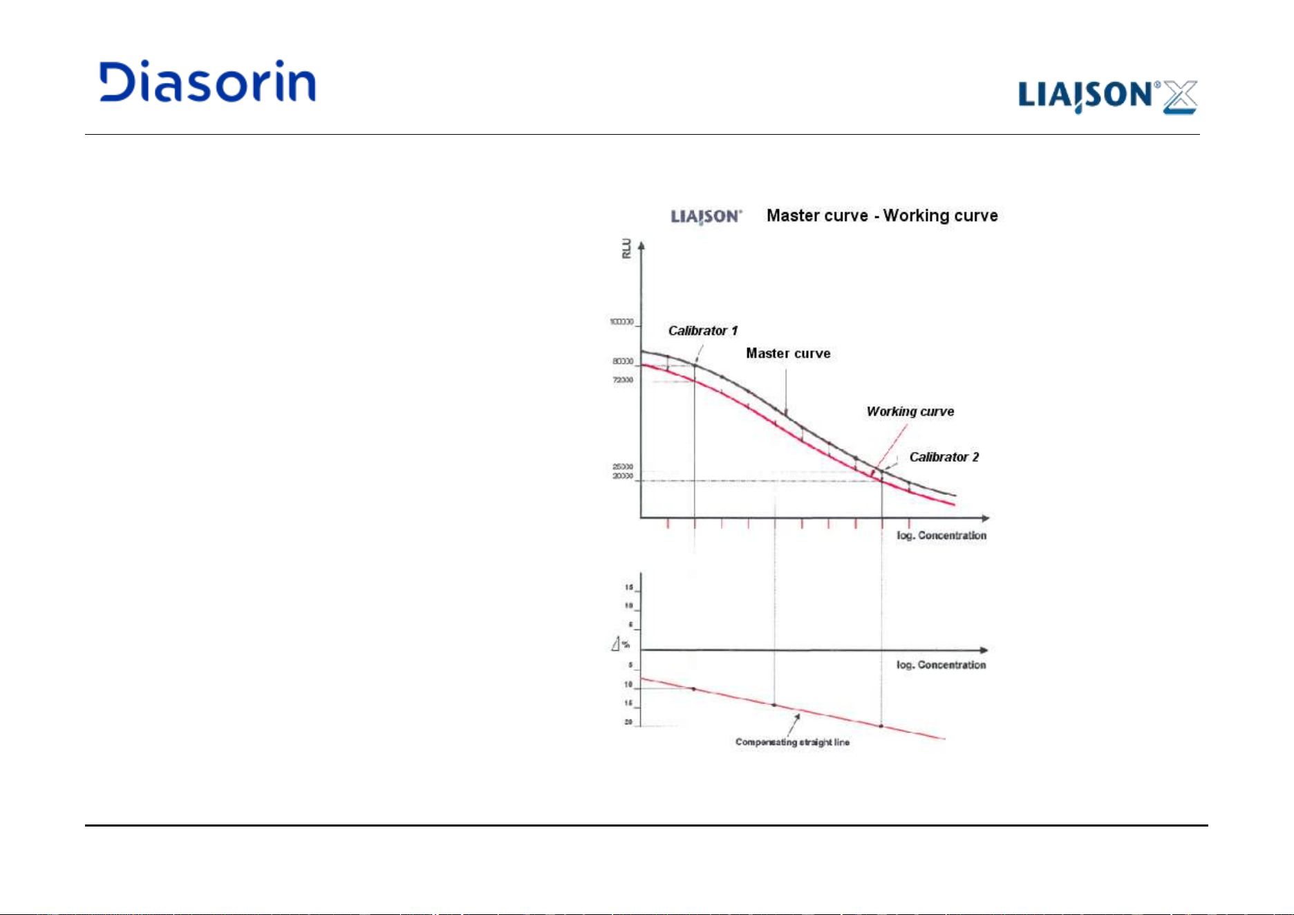
3 Measuring Principle of the LIAISON
®
XL Immunoassays
LIAISON XL - Instructions for use Page 3-7
Rev. L
3.4 Calibration (quantitative)
Data reduction is performed using a master curve
with 2-point recalibration.
The starting point of data reduction is the master
curve, stored in the analyzer.
To compensate for differences between reagent
lots, different analyzers and environmental
conditions, assay calibration must be run and
validated according to the indications reported in
the assay Instructions for Use (indications may
vary per assays).
The measuring signals of the calibrators allow the
shift of all master curve points to a working curve,
corresponding with the actual conditions during
measurement. See the following example.
Figure 3-4: Calibration concept: example
3 Measuring Principle of the LIAISON
®
XL Immunoassays
Page 3-8 LIAISON XL - Instructions for use
Rev. L
• The stored master curve is generally defined with 10 master curve base points.
• Two calibrators with defined concentration values are measured. These measured signals (RLU) are compared with the master curve
signal of the corresponding calibrator concentrations.
• The relative difference between the measured RLU and the master RLU of the calibrators is calculated and a linear extrapolation is
performed between the recalculated RLU (Y-axis) and the logarithmic (Log) concentrations (X-axis).
• Based on appropriate compensation factors, a re-adjustment of the master curve points is made in order to achieve, by a “cubic spline
function”, the working curve.
Wrong Results!
For continuous safety of the diagnostic results, quality control measures are to be maintained, such as routine
controls or calibration issues, which are defined in this Operating Instruction.
• Safe and intended function of the LIAISON
®
XL Diagnostic System can only be expected with the use of
LIAISON
®
XL controls approved by
DiaSorin Italia S.p.A.
• Observe instructions in IFU of the reagents for Qualiy Control of the assay.
Brief description:
3 Measuring Principle of the LIAISON
®
XL Immunoassays
LIAISON XL - Instructions for use Page 3-9
Rev. L
3.5 Calibration (qualitative)
The calculation of a reference level, the cut off (CO), is performed as a linear combination of terms, dependant upon system base signal and
calibrators’ RLU. Formula applied is the following:
cRLUbRLUaCO
calcal
++=
21
Analytical result is reported as index, the ratio of the unknown sample signal RLU
sample
vs the CO:
CO
RLU
I
sample
=
Two kinds of QCal are possible, depending upon the number of calibrators:
1. in one point qualitative, only calibrator 1 is present: coefficients given are a and c only;
2. in two points qualitative, both calibrator 1 and 2 are present: all three coefficients a, b and c are given.
Validation of calibration is possible if results scored by the calibrator(s) lie within the related acceptance ranges.
After validation, the cut off is then calculated from the formula above.
4 System Description
LIAISON XL - Instructions for use Page 4-1
Rev. L
4 System Description
4.1 Overview
4.1.1 Materials required but not provided
In order to perform immunoassays, the following materials are needed beside specific assay kits:
LIAISON
®
XL Cuvettes (code X0016).
LIAISON
®
XL Disposable Tips (code X0015).
LIAISON
®
Disposable Tips (code X0055).
LIAISON
®
XL Starter Kit (code 319200).
LIAISON
®
EASY Starter Kit (code 319300).
LIAISON
®
Wash/System Liquid (code 319100).
LIAISON
®
XL Waste Bags (code X0025).
Refer to the Assay IFU of the products for details about the materials that can be used.
4 System Description
Page 4-2 LIAISON XL - Instructions for use
Rev. L
4.1.2 LIAISON
®
XL System
1
Left blind cover
2
Left top cover
3
Right top cover
4
Right blind cover
5
Front Module (throw in for cuvettes, drawers for disposable tip trays,
loading bays for samples, reagents and starter reagents)
6
Cabinet for liquid tanks, waste liquid tanks, solid waste and PC
7
Extensible board
8
Integrated re-suspension tool
9
Touch screen
Opening the cover during system operations may result in operation interruption and no reported results.
In case it would be necessary to open the cover, make sure to pause the pipettors (see chapter 6.2.1) and wait
for 30’’ before opening the cover. This action avoids unnecessarily not reporting results.
Remove the pause condition (see chapter 6.2.1) after cover closure to allow pipettor regular operations.
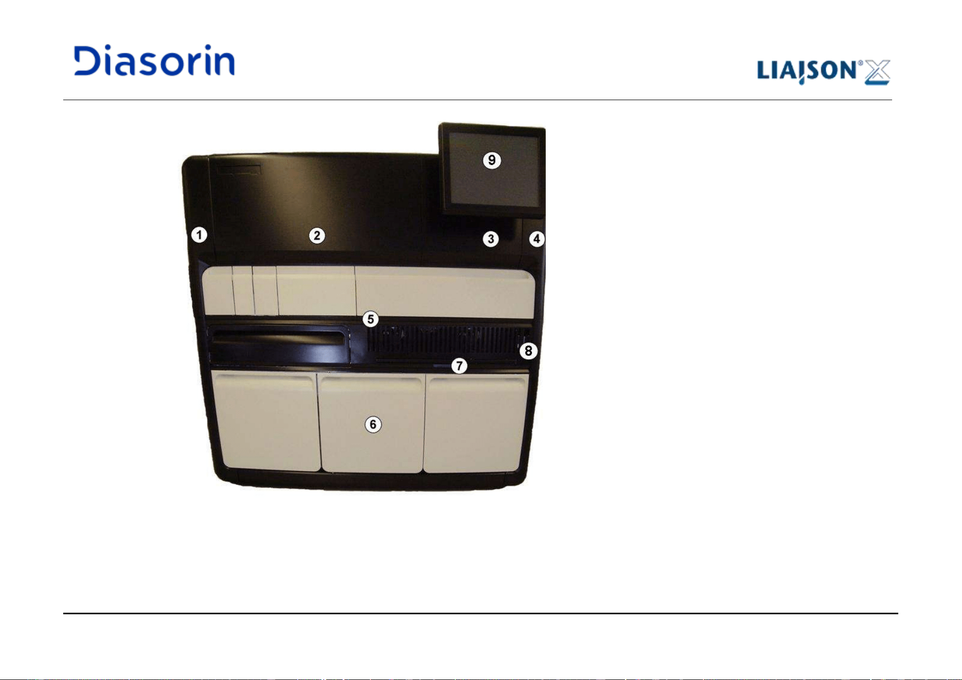
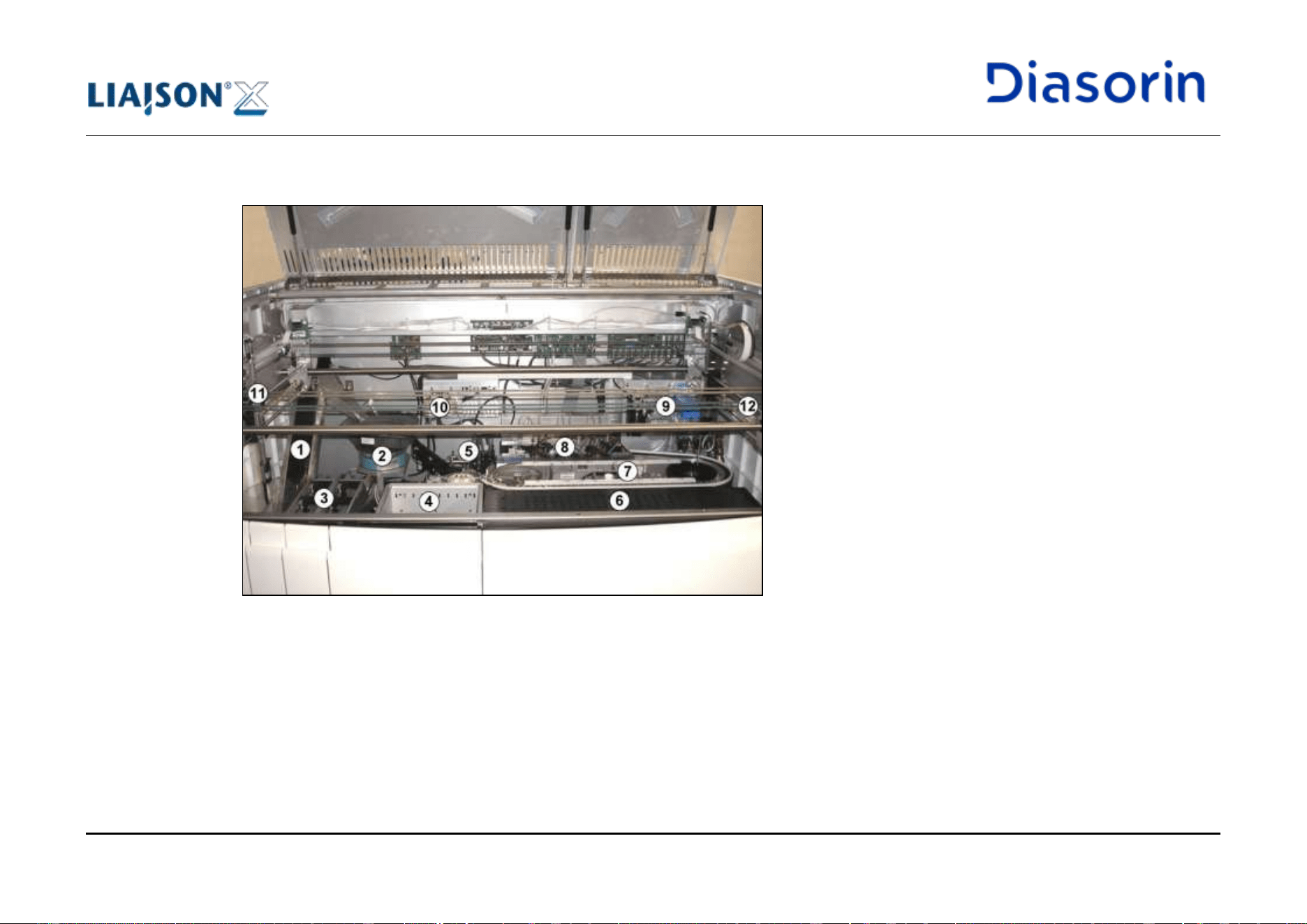
4 System Description
LIAISON XL - Instructions for use Page 4-5
Rev. L
1
Cuvette transport (Auger)
2
Cuvette orientation mechanism (Sorter)
3
Disposable Tip Drawers
4
Loading bay for sample racks
5
Reader
6
Loading bay for reagents and ancillaries
7
Incubator and Wash / Waste station
8
Washer
9
Pump Rack
10
Starter Reagent Pumps
11
Air pipettor with disposable tip adapter for sample pipetting (Left Arm)
12
Pipettor with steel needle for reagent pipetting (Right Arm)
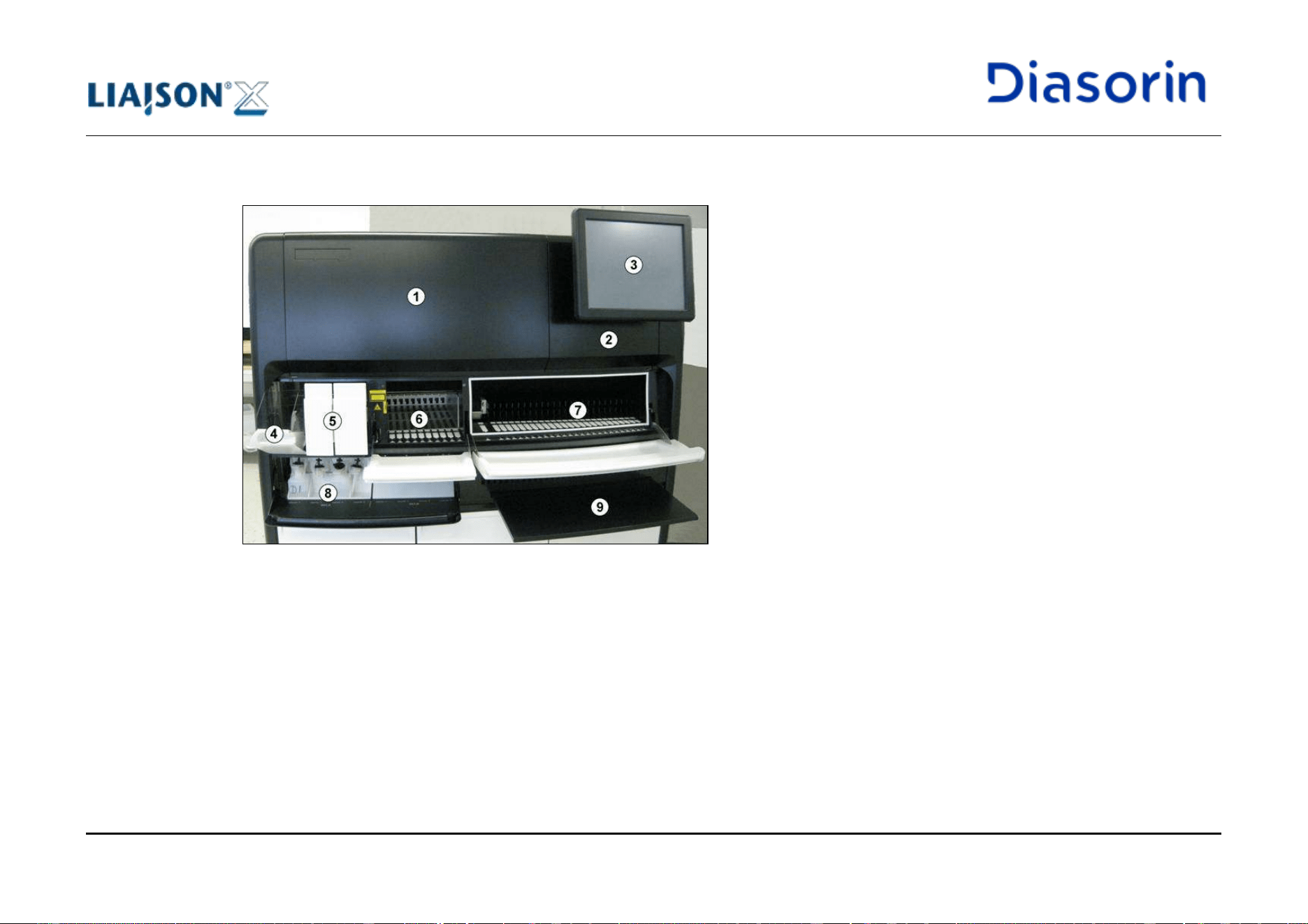
4 System Description
LIAISON XL - Instructions for use Page 4-7
Rev. L
1
Left Top Cover
2
Right Top Cover
3
Touch screen
4
Reservoir for cuvettes
5
Drawers for disposable tip trays
6
Loading bay for sample racks
7
Loading bay for reagents (integrals or ancillary reagents)
8
Loading area for starter reagents
9
Extensible board
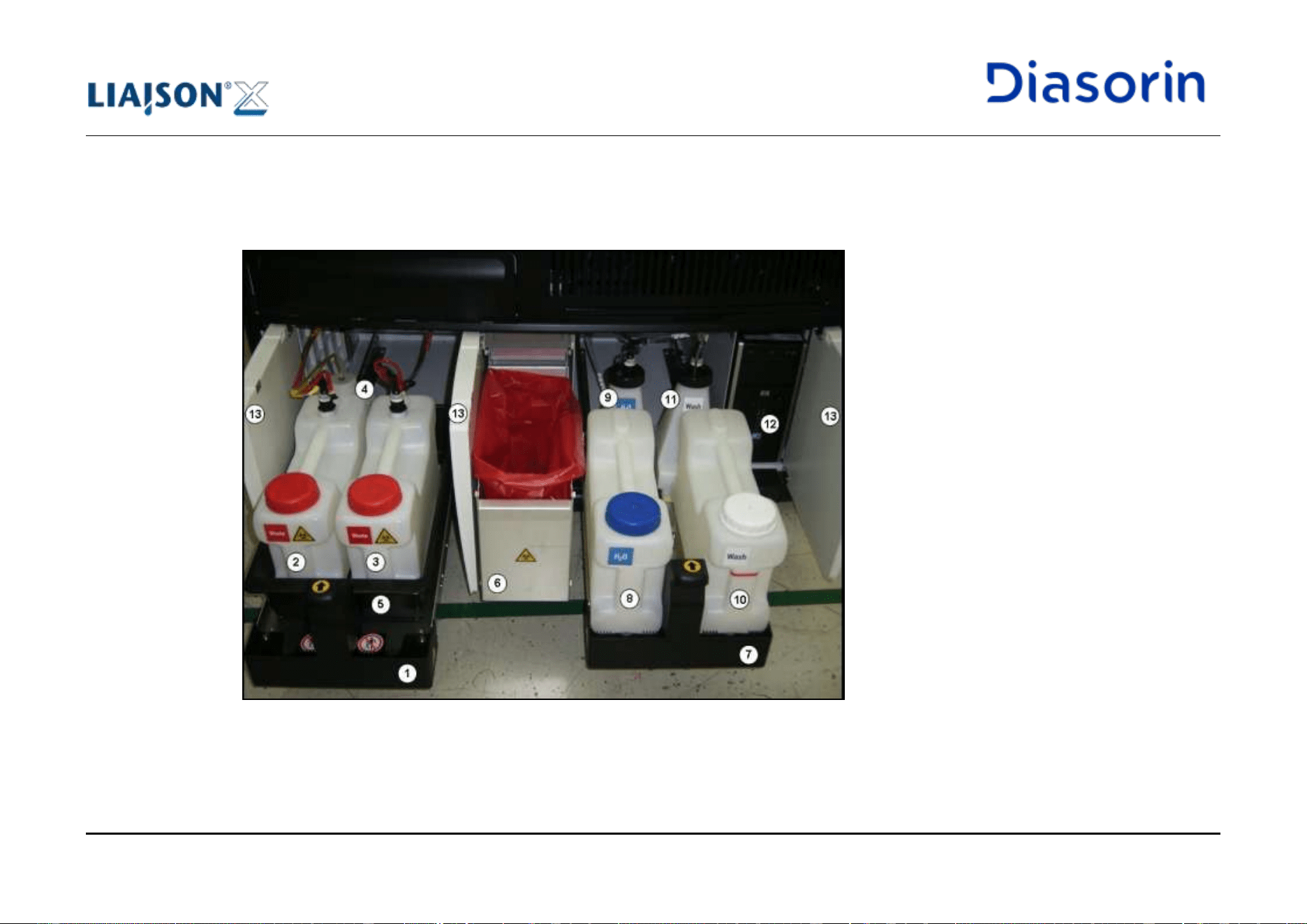
4 System Description
LIAISON XL - Instructions for use Page 4-9
Rev. L
1
Left drawer
2
Liquid waste tank, Left
3
Liquid waste tank, Right
4
Cleaning solution tank
5
Waste basin
6
Solid waste drawer
7
Right drawer
8
Water tank
9
Intermediate tank (Water)
10
Wash buffer tank
11
Intermediate tank (Wash buffer)
12
PC
13
Cabinet doors
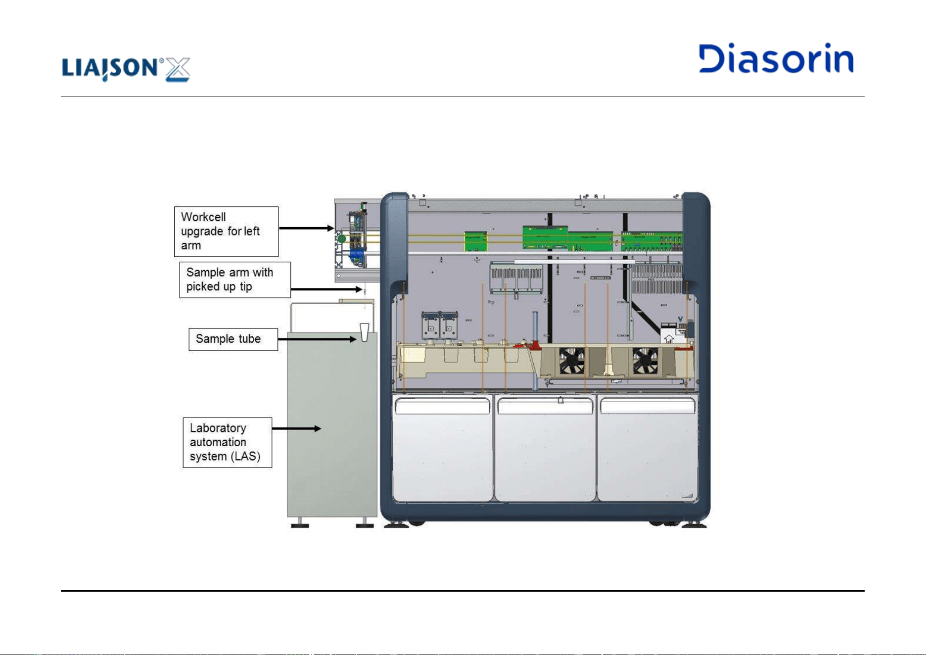
4 System Description
Page 4-10 LIAISON XL - Instructions for use
Rev. L
4.1.6 LIAISON
®
XL with Workcell Upgrade Kit
A modified version of the LIAISON
®
XL Diagnostic System, called LIAISON
®
XL with Workcell Upgrade Kit, is designed to allow
compatibility with certain types of laboratory automation systems (LAS). As can be noticed in Figure 4-5, the pipettor module is expanded, in
order to allow the sample arm to aspirate samples coming from a laboratory automation system.
Figure 4-5: LIAISON
®
XL with Workcell Upgrade Kit system
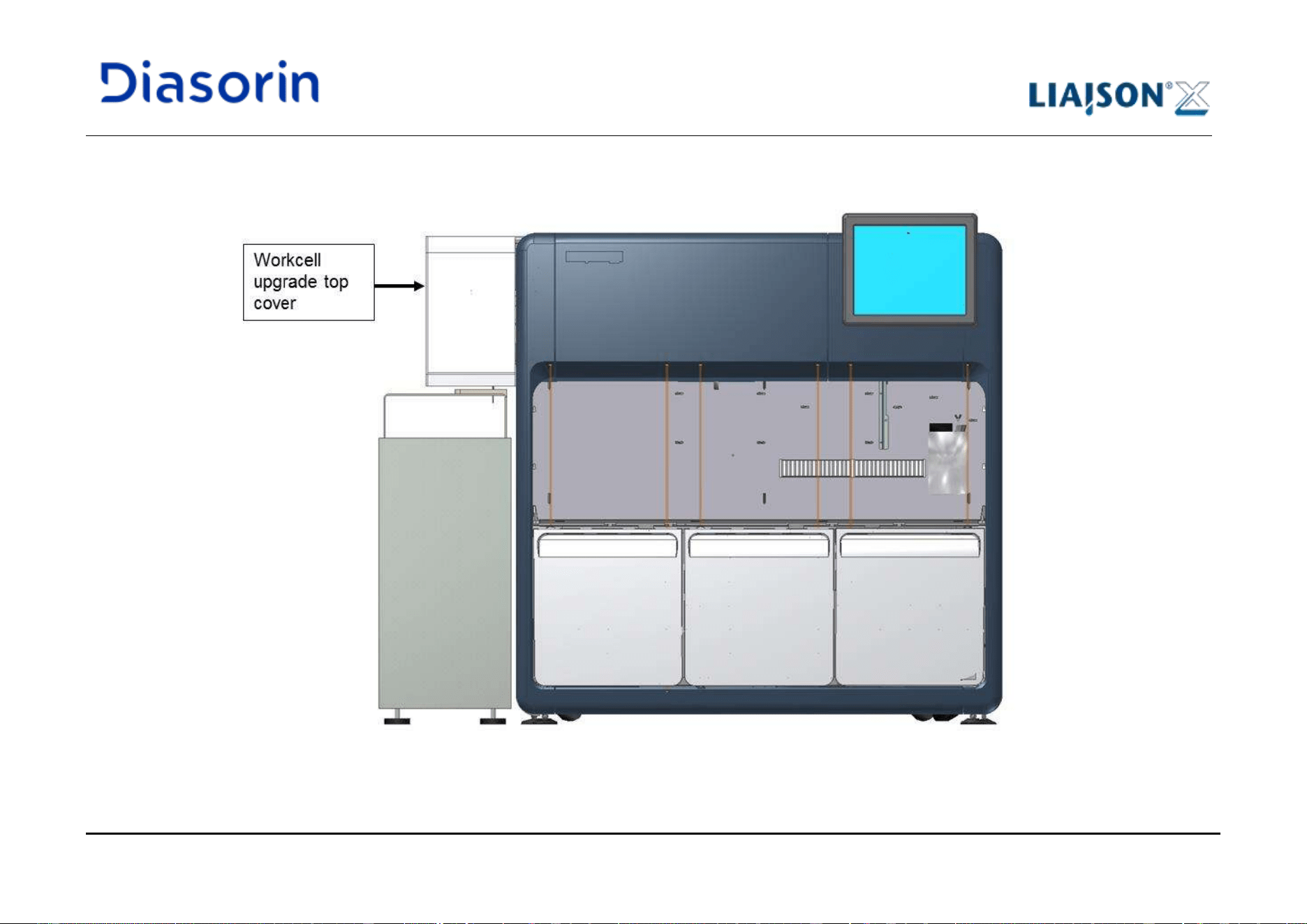
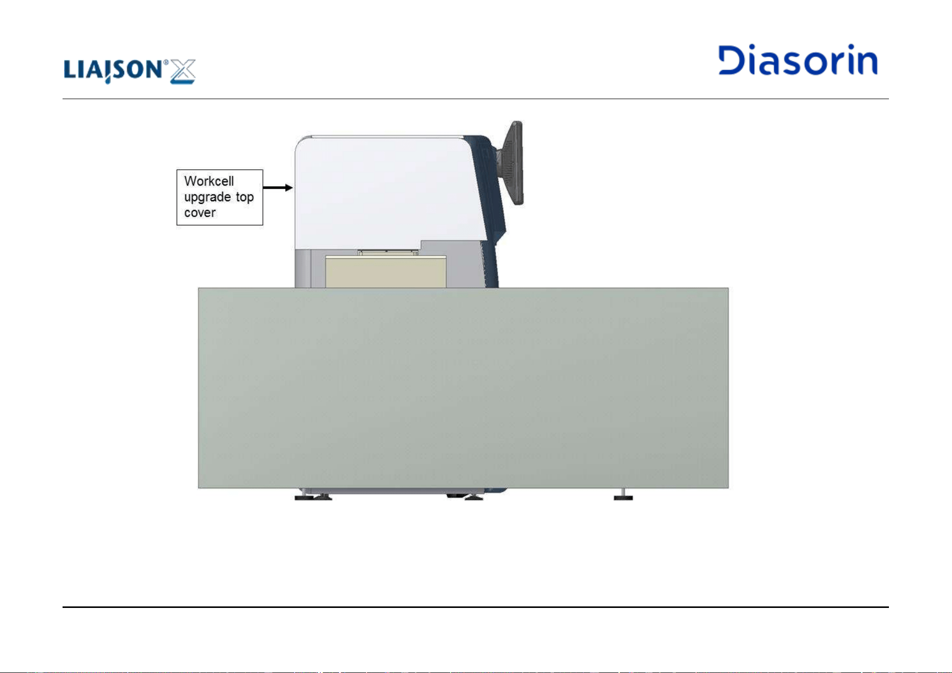
4 System Description
LIAISON XL - Instructions for use Page 4-13
Rev. L
4.1.7 Glossary
Ancillary (reagents)
Anything that can be introduced by operator into Ancillary Area rack, including external reagents for
some kits and Light Check
Barcode Reader
Assembly to read the sample barcode
BGW
Test to check quality of instrument washing
Control Rack
9 or 6 positions module to host some types of control bottles and external calibrators
Cuvette
Single cavity plastic module, in which immunometrical reaction can take place
CV%
Statistical variable that shows dispersion rate of measurements
Incubator
80 positions assembly in which cuvettes are incubated and pipetted
Instrument
Part of LIAISON
®
XL system that contains only the LIAISON
®
XL analyzer and tanks, but not PC,
printer and connection cables
Integral
Reagent cartridge (made up of vials) to be inserted into the Reagent Area
Integral Holder
Holder used for the handling of integrals outside the instrument. Up to 14 integrals can be transported
together.
Kit
Set of reagents used to carry out a specific assay; it may consist of one or more integrals, external
calibrators and ancillary reagents.
LC-le
Test to verify accuracy of the left dispensing pipettor, carried out by Light Check solution
LC-ri
Test to verify accuracy of the right dispensing pipettor, carried out by Light Check solution
Light Check
Test tool provided as lyophilised material
Light Check adaptor
Plastic adaptor used to insert the Light Check bottles into the Ancillary Area rack
Reader
Reading area in which chemical reaction and measurements occur
Prime
Start-up cycle for individual parts of instrument involved in fluidics, carried out by usage of DI Water,
Wash Buffer, Starter Reagents and Cleaning Solution
Pusher
Exchanges cuvettes between incubator and washer or cuvette loading mechanism
Rack Holder
12 positions holder used for the handling of sample and control racks outside the instrument.
4 System Description
Page 4-14 LIAISON XL - Instructions for use
Rev. L
Reagent Area
Integral and ancillary loading area
RF-Tag
Micro-chip present on integrals, starters and ancillaries to allow recognition and data storage
RLU
Relative Light Unit (signal measurement unit)
Sample Area
Loading area for samples
Sample Rack
12 positions module to host sample tubes
Samples
Anything that can be introduced by operator into Sample Area racks, including patient samples,
controls and external calibrators
Solid Waste Bin
Plastic removable container to increase safety during waste bag disposal
Solid Waste Drawer
Drawer of the system used to host waste bags and the solid waste bin (if equipped)
Starter (reagents)
Reagents dispensed during the reading to generate chemiluminescent signal
System
The complete structure installed in the laboratory
Tip
Single cavity plastic probe used to aspirate samples with left pipettor arm
Tray
96 positions modules equipped in the Disposable Tip drawers to host tips
Vial
Container for just one reagent; more vials form an integral
Wash Buffer
Solution (to be diluted 1:10 in distilled H
2
0) used to wash cuvettes
Wash Station
Washing well for right pipettor needle
Waste Bag
Container for used cuvettes and tips
Waste Basin
Container used to collect spillage of contaminated liquid coming from broken waste tanks
4 System Description
LIAISON XL - Instructions for use Page 4-15
Rev. L
4.2 Use of the Modules
In the following chapters, the individual modules and their use are explained.
4.2.1 Touch Screen and On Screen Keyboard
The integrated touch screen is needed to use the system. All inputs are made with a stylus (tip R0.8 or over) or finger directly on the touch
screen. The usage of an external keyboard or mouse is not validated therefore it is not supported.
Touch Screen Handling
• Operate with a stylus (tip R0.8 or over), or with a finger without applying excessive pressure.
• Avoid using sharp edged or hard articles.
• Avoid drawing lines along with the edge of the housing which may damage the PET/FILM and cause the failure of the touch panel due to
extreme force.
• Keep the surface clean by executing periodic maintenance (see chapter 8.9).
Improper use could damage the touch screen surface.
Use:
• Mouse emulation:
o Mouse pointer: Touch the screen with a finger or a stylus and the mouse pointer will follow the moving object.
o Single mouse click: Touch the screen once.
o Double mouse click (double click): Touch the screen twice. Do not wait between the first and the second touch.
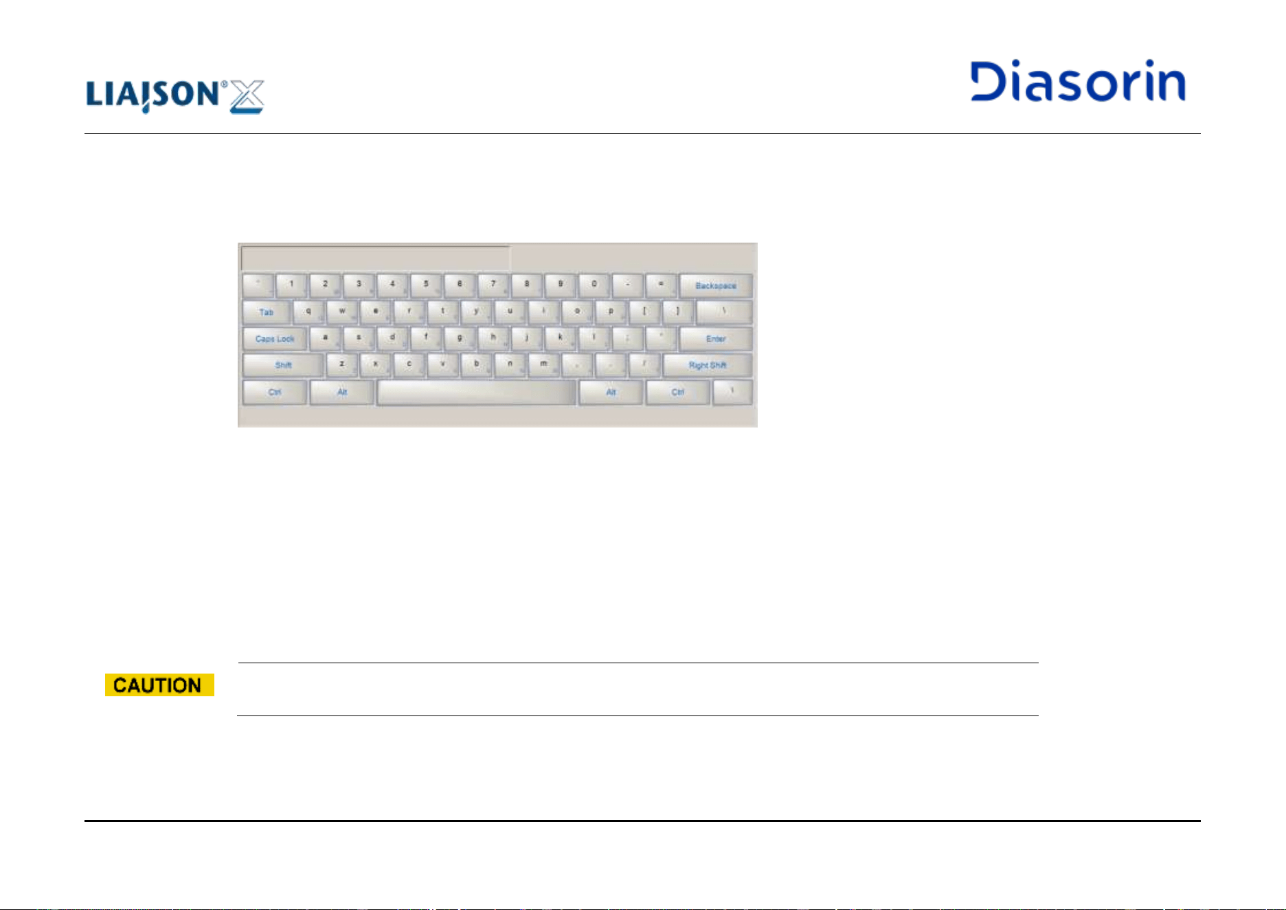
4 System Description
Page 4-16 LIAISON XL - Instructions for use
Rev. L
• On screen keyboard (alphanumeric inputs, e.g. A - Z, 0 - 9, etc):
The LIAISON
®
XL software provides for input boxes an on screen keyboard to enter letters or numbers. The on screen keyboard is shown
automatically after touching an input box. A smaller version is provided for numerical input. The keyboard shows on the top left corner the
current edit field content.
Figure 4-8: On screen keyboard (alphanumerical version)
4.2.2 Barcode Reader
A handheld barcode reader is supplied with the system, in order to allow the user to read bi-dimensional barcodes for control definition.
The following models are available: PN A0096, PN A0179 and PN A0256.
In case of PN A0096 model, a dedicated support (Figure 4-9.b) can be placed in the cabinet, just in front of the PC, and can be used to hold
the barcode reader when it is not in use (Figure 4-11); the support can be fixed to the system using the velcro strips (Figure 4-10) attached by
the technician during the installation.
Do not use the handheld barcode reader for purposes different from reading bi-dimensional control definitions.
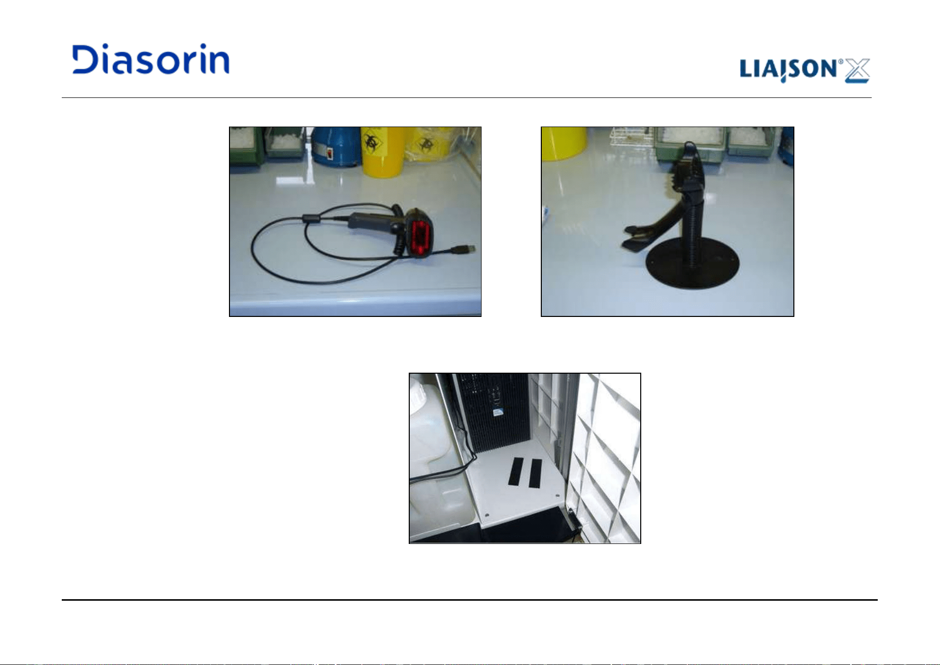
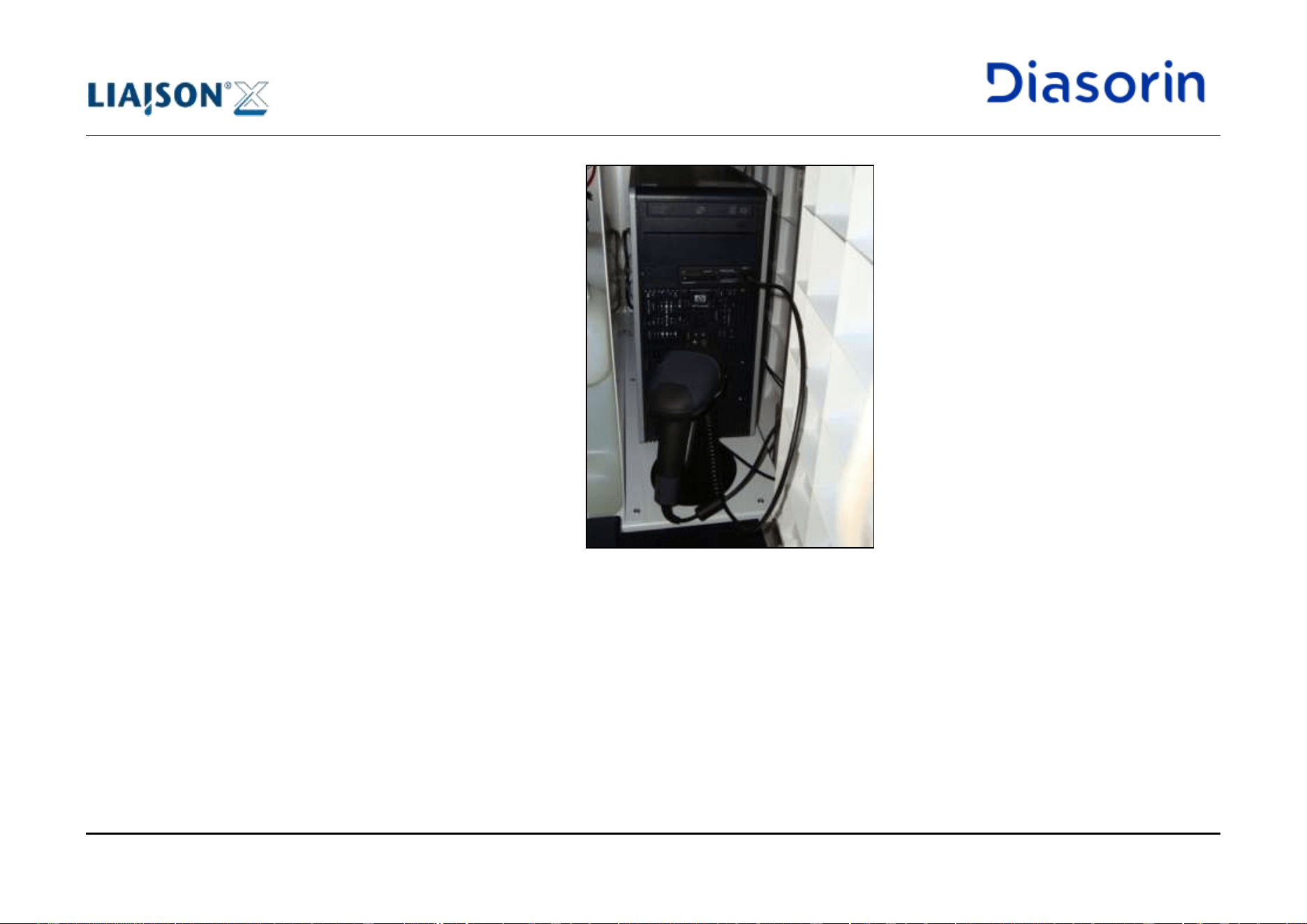
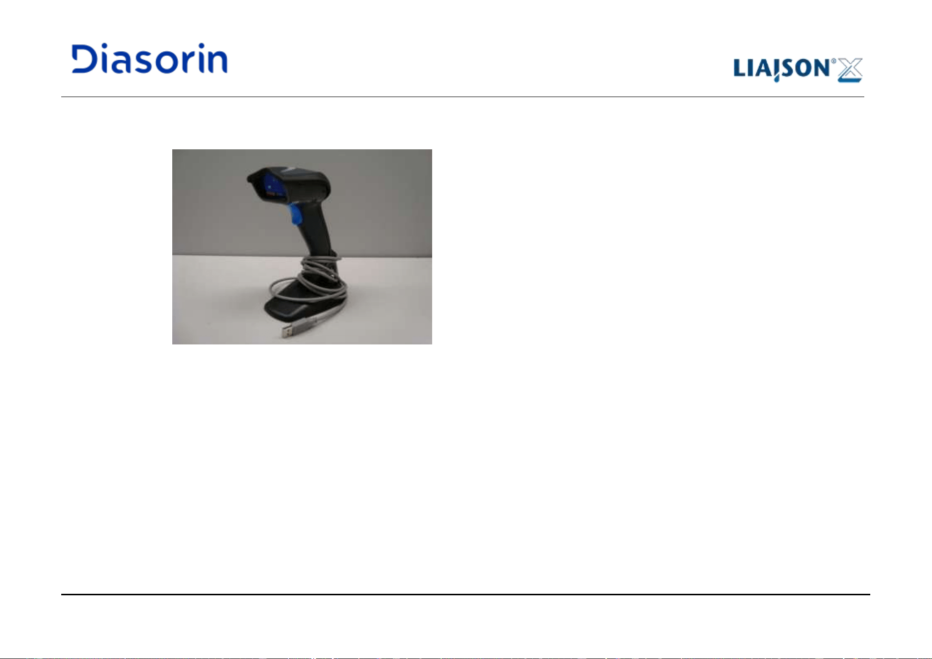
4 System Description
LIAISON XL - Instructions for use Page 4-19
Rev. L
In case of use of PN A0179 and PN A0256 handheld barcode reader, the velcro strips previously placed into the cabinet for the fixation of the
support are no more necessary. In any case it is suggested to place a not-in-use barcode reader into the cabinet, just in front of the PC.
Figure 4-12: Handheld barcode reader (PN A0179 and PN A0256) with integrated support
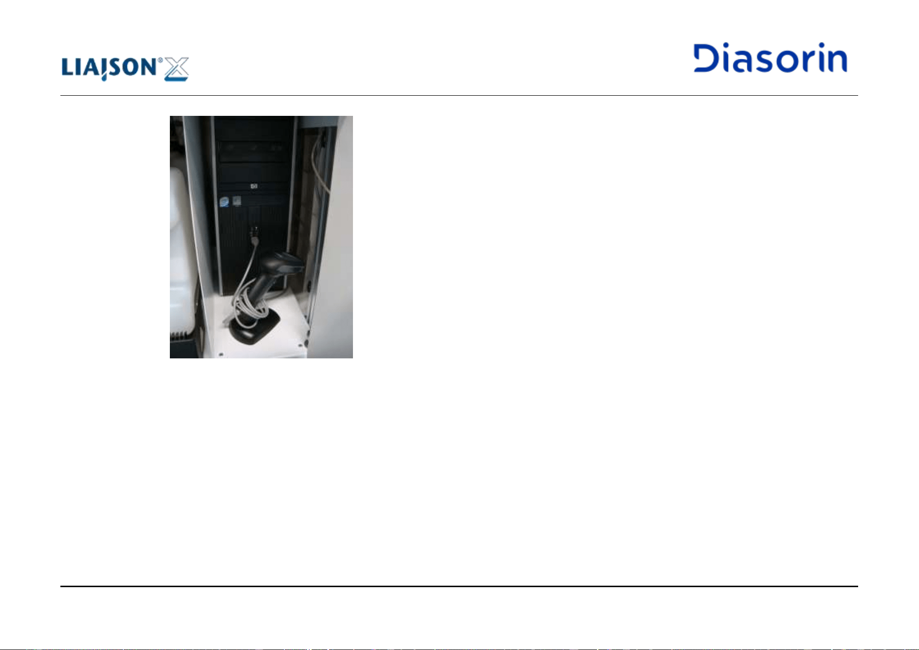
4 System Description
Page 4-20 LIAISON XL - Instructions for use
Rev. L
Figure 4-13: Handheld barcode reader (PN A0179 and PN A0256) placed into the cabinet
4.2.3 Reservoir for Cuvettes
The reservoir for cuvettes allows continuous loading of the LIAISON
®
XL system with cuvettes. The cuvettes must be loaded in units of 200
pieces (1 bag) and remain in the reservoir until they are utilized. The management of the cuvettes in the system is performed by the
LIAISON
®
XL software.
The loading of the cuvettes is described in chapter 5.5.1.
4 System Description
LIAISON XL - Instructions for use Page 4-21
Rev. L
4.2.4 Drawers for Disposable Tip trays
With two independent drawers for disposable tip trays, a continuous refilling of disposable tips and therefore an uninterrupted operation of the
system is possible.
Every drawer can be filled with up to three disposable tip trays with 96 disposable tips each. The loaded disposable tip trays are recorded by
the LIAISON
®
XL software (see chapter 6.10.2). An automatic consumption meter allows the exact indication of the disposable tips still
present in the instrument.
The loading of the disposable tip trays is described in chapter 5.5.2.
A LED below the relevant drawer shows the current usage status:
Description
Status
Action
The drawer is closed and currently being used.
LED ON
Do not open the drawer.
The drawer is closed and not in use.
LED OFF
It is possible to open the
drawer.
The drawer is open.
LED slow flashing
It is possible to close the
drawer.
Table 4-1: LEDs on the disposable tip drawers
LEDs
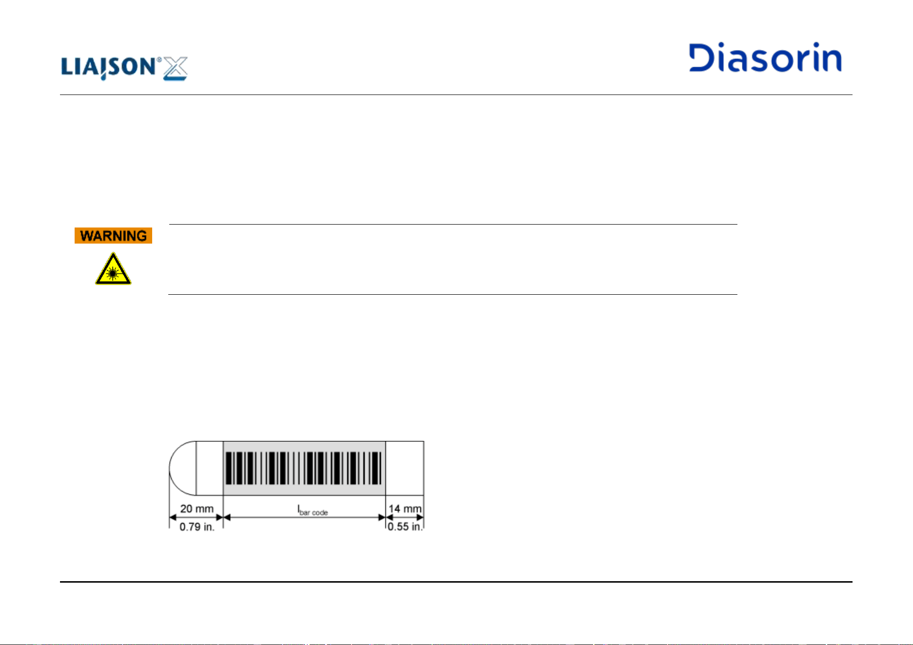
4 System Description
Page 4-22 LIAISON XL - Instructions for use
Rev. L
4.2.5 Loading Bay for Sample Racks
The loading bay for sample racks allows continuous loading of the LIAISON
®
XL system with samples. The samples in the tubes are placed in
special racks and loaded in one of the 10 lanes afterwards. As support, a LED below each lane indicates the relevant usage status
(see below).
To prevent confusion, a distinct identification number must be assigned to every sample in the LIAISON
®
XL software. This sample ID can be
entered either by scanning the bar-code using the barcode scanner located in the loading bay for sample racks or typing it manually.
See chapter 1-16 for Laser Safety.
To ensure the bar-code scanner can read the bar-code label correctly, the bar-code label must be of a good quality, thus meaning it shall
match Category A or B (according to ANSI X3.182 standard) or category 4 and 3 (according to ISO/IEC 15416 standard).
In addition, the following specifics shall be matched:
1) The module width (i.e. the width of the smallest bar or gap in the barcode) shall be in the range 0.167 mm ≤ width ≤ 0.5 mm.
2) For Codabar and 2/5 Interleaved typologies, the bar width ratio (i.e. the comparison in bar widths between the narrow modules and the
wide modules) shall be in the range 1:2.5 ≤ ratio ≤ 1:3 (if 0.167 mm ≤ width < 0.2 mm) or in the range 1:2 ≤ ratio ≤ 1:3 (if 0.2 mm ≤ width ≤
0.5 mm).
Regarding the positioning, the barcode must be applied to the grey section in the middle of the tube as shown in Figure 4-14.
Figure 4-14: Bar-code label on the tube
4 System Description
LIAISON XL - Instructions for use Page 4-23
Rev. L
Length of tube:
Max. length of bar-code (l
bar code
)
66 mm (2.60 in.)
32 mm (1.26 in.)
75 mm (2.95 in.)
41 mm (1.61 in.)
100 mm (3.94 in.)
66 mm (2.60 in.)
Table 4-2: Length of bar-code label
Ensure that the bar-code labels face towards the left (open side of the rack) when loading otherwise they cannot be properly read.
In addition to the sample racks, racks with calibrators and controls may be loaded in the loading bay for sample racks.
The loading with racks is described in chapter 5.6.
A LED below each lane indicates the current usage status when the flap is open, while the status “slow flashing” is not shown with the flap
closed:
Description
Status
Action
The sample rack is currently being used or could be used soon for a test.
LED ON
Do not remove it
Without sample rack in the lane:
• The lane is not activated, and cannot be used to load a sample rack.
LED OFF
Do not load a sample rack
in this lane
With sample rack in the lane:
• The samples of this rack are not used or scheduled.
LED OFF
It is possible to remove it.
The lane is activated, and can be used to load a sample rack.
LED slow flashing
(once per second)
Insert the next sample rack
into this lane.
The sample rack has not been recognized.
LED fast flashing
(three times per second)
Remove the sample rack
and insert it again.
Table 4-3: LEDs on the loading bay for sample racks
LEDs
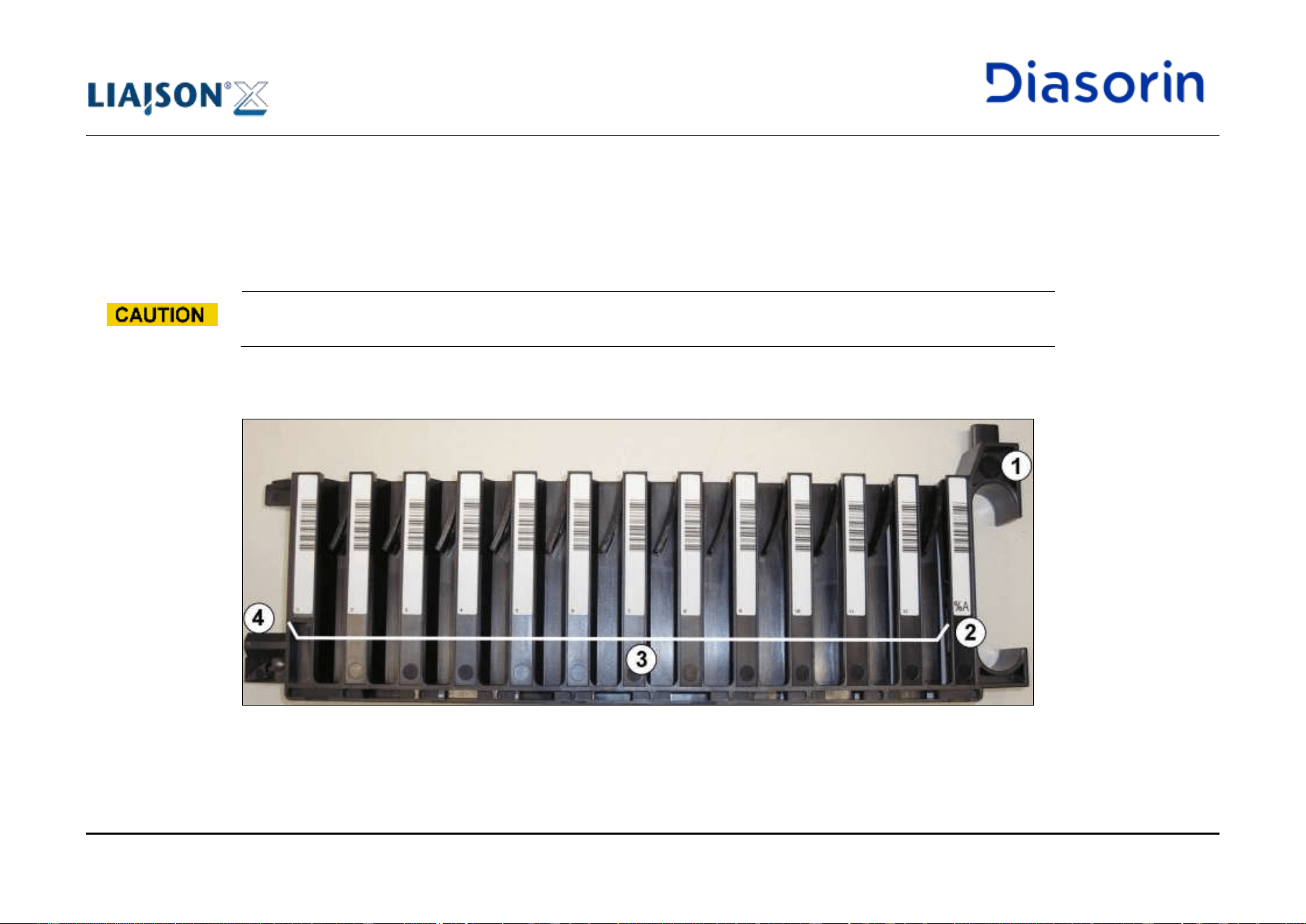
4 System Description
Page 4-24 LIAISON XL - Instructions for use
Rev. L
4.2.5.1 Sample Racks
A sample rack is a holder to store patient samples (placed in sample tubes) for use on the analyzer. The sample rack (also known as "patient
rack" or "rack") is designed to hold up to 12 sample tubes (bar-coded or non-bar-coded) and is to be inserted into the analyzer in a way such
to be registered by the analyzer and supports the sample tubes during aspiration by the sample probes.
Only the supplied LIAISON
®
XL approved sample racks may be used. The use of unauthorized rack types is
prohibited and may cause damage to the system.
All sample racks have the same structure as pictured and described below. The positions are numbered from 1 through up to 12 with number
1 starting farthest away from the handle.
Figure 4-15: Sample rack A
4 System Description
LIAISON XL - Instructions for use Page 4-25
Rev. L
1
Handle
2
Sample rack identification bar-code label
3
Sample tube positions with position bar-code label and a clamp for correct position holding of sample tube
4
Clamp to lock the sample rack into the loading bay for sample racks
4.2.5.2 Control Racks
9-position Control Rack
A 9-position control rack is a holder to store some types of control bottles and external calibrators for use on the analyzer. The 9-position
control rack (also known as C rack) is designed to hold up to 9 bottles (bar-coded or non-bar-coded) and is to be inserted into the analyzer in
a way such to be registered by the analyzer and supports the bottles during aspiration by the sample probes.
A set of 2 9-position control racks is provided with each instrument.
Only the supplied LIAISON
®
XL control racks may be used. The use of unauthorized rack types is prohibited and
may cause damage to the system.
9-position control rack has to be used only on LIAISON
®
XL systems whose sample bay is not equipped with the top
cover (see next picture).
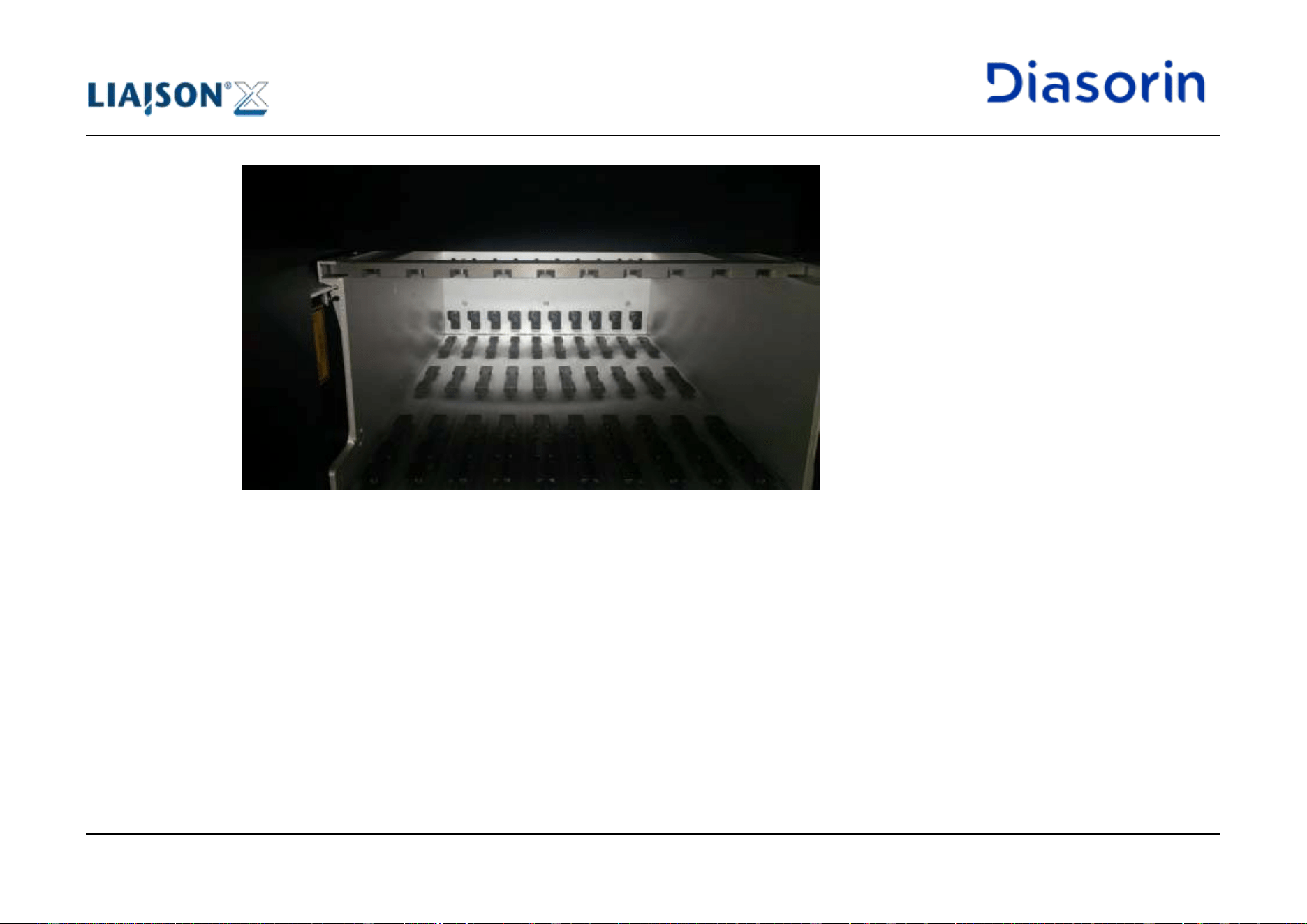
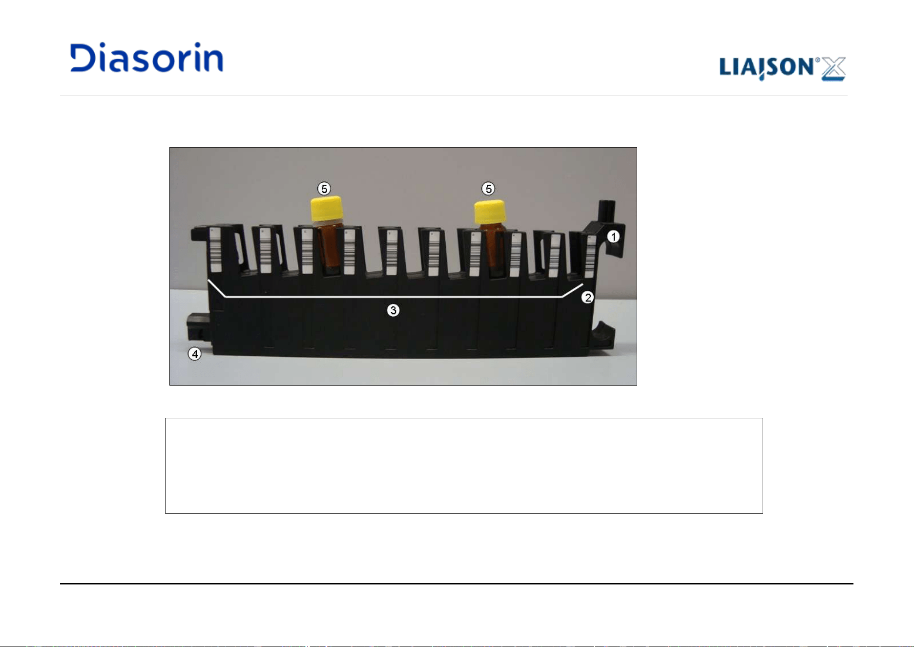
4 System Description
LIAISON XL - Instructions for use Page 4-27
Rev. L
9-position control racks have the structure as pictured and described below. The positions are labeled from A through up to I with label A
starting farthest away from the handle.
Figure 4-17: 9-position Control Rack
1
Handle
2
Control rack identification bar-code label (%C)
3
Bottle positions with position bar-code label and position holding
4
Clamp to lock the control rack into the loading bay of the analyzer
5
Control bottles or external calibrators placed inside the rack
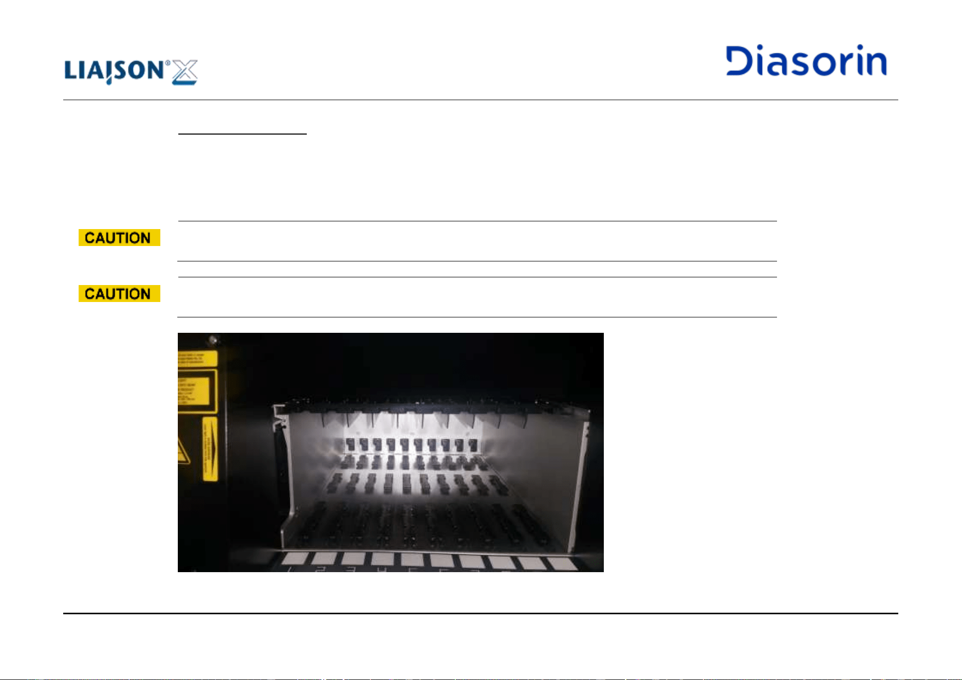
4 System Description
Page 4-28 LIAISON XL - Instructions for use
Rev. L
6-position Control Rack
A 6-position control rack is a holder to store some types of control bottles and external calibrators for use on the analyzer. The 6-position
control rack (also known as T rack) is designed to hold up to 6 bottles (bar-coded or non-bar-coded) and is to be inserted into the analyzer in a
way such to be registered by the analyzer and supports the bottles during aspiration by the sample probes.
A set of 3 6-position control racks is provided with each instrument.
Only the supplied LIAISON
®
XL control racks may be used. The use of unauthorized rack types is prohibited and
may cause damage to the system.
6-position control rack is designed to fit on LIAISON
®
XL systems whose sample bay is equipped with the top cover
(see next pictures), but it can be used on any LIAISON
®
XL systems.
Figure 4-18: Sample bay equipped with top cover (front view)
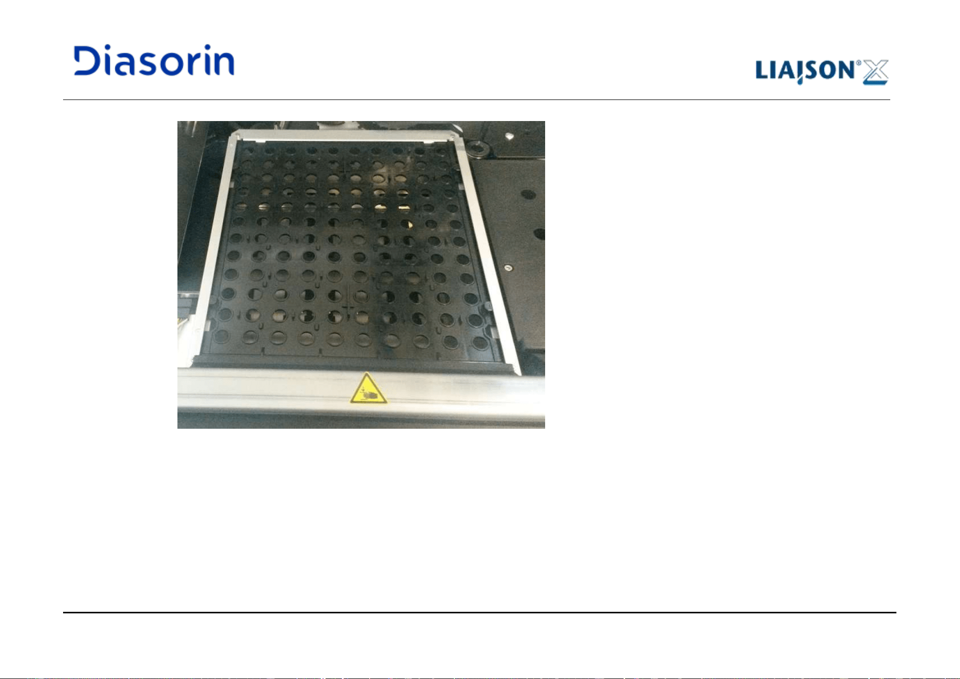
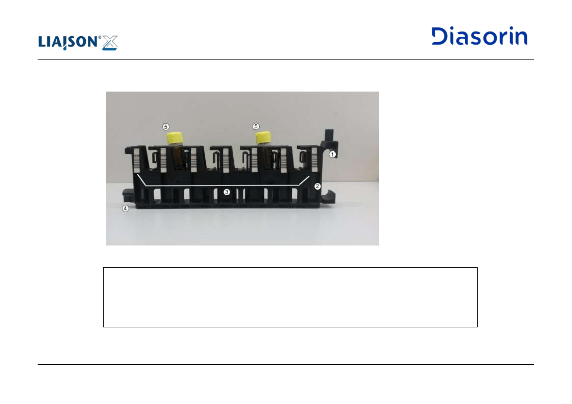
4 System Description
Page 4-30 LIAISON XL - Instructions for use
Rev. L
6-position control racks have the structure as pictured and described below. The positions are labeled from A through up to F with label A
starting farthest away from the handle.
Figure 4-20: 6-position Control Rack
1
Handle
2
Control rack identification bar-code label (%T)
3
Bottle positions with position bar-code label and position holding
4
Clamp to lock the control rack into the loading bay of the analyzer
5
Control bottles or external calibrators placed inside the rack
4 System Description
LIAISON XL - Instructions for use Page 4-31
Rev. L
4.2.5.3 Rack Types, Tube Diameter and Dead Volume
There are 19 different types of racks (see the table below). The different types of racks refer to the inner diameter and the total height of the
sample tubes and are important for the proper management of samples. As can be noticed, together with standard rack types, 5 typologies
(X, Y, Z, G, H) can be directly customized by field service engineers according to user requirements.
Rack type:
Internal diameter of the sample tubes:
Total height of the sample tubes:
Dead volume:
Q
6 mm
≤ 55 mm
150 µL
N
7 mm
≤ 55 mm
150 µL
K
8 mm
≤ 55 mm
150 µL
J
9 mm
56 mm - 65 mm
150 µL
A
10 mm
86 mm - 100 mm
150 µL
I
11 mm
86 mm - 100 mm
200 µL
F
12 mm
86 mm - 100 mm
250 µL
E
13 mm
86 mm - 100 mm
300 µL
W
14 mm
86 mm - 100 mm
350 µL
B
15 mm
86 mm - 100 mm
400 µL
D
Use only for DiaSorin special large vials
(i.e. some types of control bottles or
external calibrators and on systems not
equipped with sample bay top cover)
G
Request Technical Assistance
Request Technical Assistance
Request Technical Assistance
H
Request Technical Assistance
Request Technical Assistance
Request Technical Assistance
X
Request Technical Assistance
Request Technical Assistance
Request Technical Assistance
Y
Request Technical Assistance
Request Technical Assistance
Request Technical Assistance
Z
Request Technical Assistance
Request Technical Assistance
Request Technical Assistance
4 System Description
Page 4-32 LIAISON XL - Instructions for use
Rev. L
Rack type:
Internal diameter of the sample tubes:
Total height of the sample tubes:
Dead volume:
C
Use only for DiaSorin special large vials
(i.e. some types of control bottles or
external calibrators and on systems not
equipped with sample bay top cover)
T
Use only for DiaSorin special large vials
(i.e. some types of control bottles or
external calibrators)
L
Used only for DiaSorin glass vials
(i.e. some types of control bottles or
external calibrators)
55 ±0.5 mm
P
Used only for pediatric tubes
Table 4-4: Rack types and sample tubes parameters
According to the above table, the size of the tubes that may be inserted in the sample racks ranges from 6 through 15 mm internal diameter.
The dead volume is the amount of liquid left in the sample tube that cannot be pipetted by the pipettor due to mechanical limitations and
calculations. A specific dead volume level exists for each specific tube type. When an assay is run, the user must have a minimum of the
sample amount needed to run the assay plus the dead volume amount in order to run the assay effectively.
Example:
A user wants to run 2 tests with one sample. The sample liquid is in a sample tube with 15mm diameter. According to the assay Instructions
for use, the assay requires 20 µL per test. The user will have to have a total of 440µL in the tube.
Summary:
• Tubes with 15 mm diameter: 400 µL (dead volume)
• 2 tests with 20 µL: 40 µL (usable sample volume)
• Total volume needed: 440 µL
Dead Volume
4 System Description
LIAISON XL - Instructions for use Page 4-33
Rev. L
In the case of plasma gel separator containers, the amount of sample should be at least 500µL plus the volume
required to run the test.
Insufficient or Missing Patient Sample Liquid
Insufficient or missing patient sample liquid might create erroneous sample aspirations. Therefore, a warning
message will be given together with an audible signal. The test must be repeated after a sufficient level of sample
has been inserted.
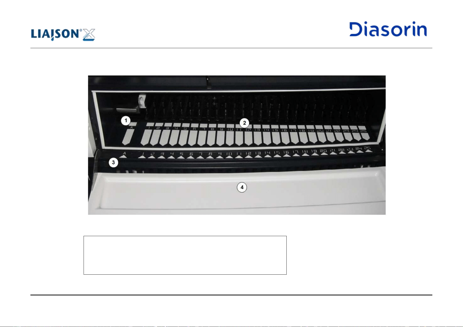
4 System Description
Page 4-34 LIAISON XL - Instructions for use
Rev. L
4.2.6 Loading Bay for Reagents (Integrals and Ancillary Reagents)
Figure 4-21: Front view of the loading bay for reagents
1
Lane for ancillary reagents and additional reagents
2
25 lanes for integrals
3
LEDs for each lane
4
Flap
4 System Description
LIAISON XL - Instructions for use Page 4-35
Rev. L
The loading bay for reagents allows a continuous loading of the LIAISON
®
XL system with reagents in the form of integrals or ancillary
reagents. As a guide, a LED below each lane indicates the relevant usage status (see below).
Integrals:
• Up to 25 integrals can be used at the same time.
• Integrals can be loaded directly into one of the 25 lanes according to the specifications of the LIAISON
®
XL.
• For the front position of the integral, a stirrer drive is provided. With the stirrer drive, magnetic particles can be evenly distributed in the
reagent.
Ancillary reagents:
• Up to 4 ancillary reagents or reagents can be used at the same time.
• Ancillary reagents must be placed in an ancillary rack with adapters before usage. Then, the ancillary rack can be loaded in the special
lane (on the very left) according to the specifications of the LIAISON
®
XL software.
Before using integrals or ancillary reagents, read the IFU (instructions for use) provided in the reagent package
(storage, preparation)!
Observe instructions for a correct re-suspension of magnetic particles.
Always use an ancillary rack in combination with the system it has been provided with.
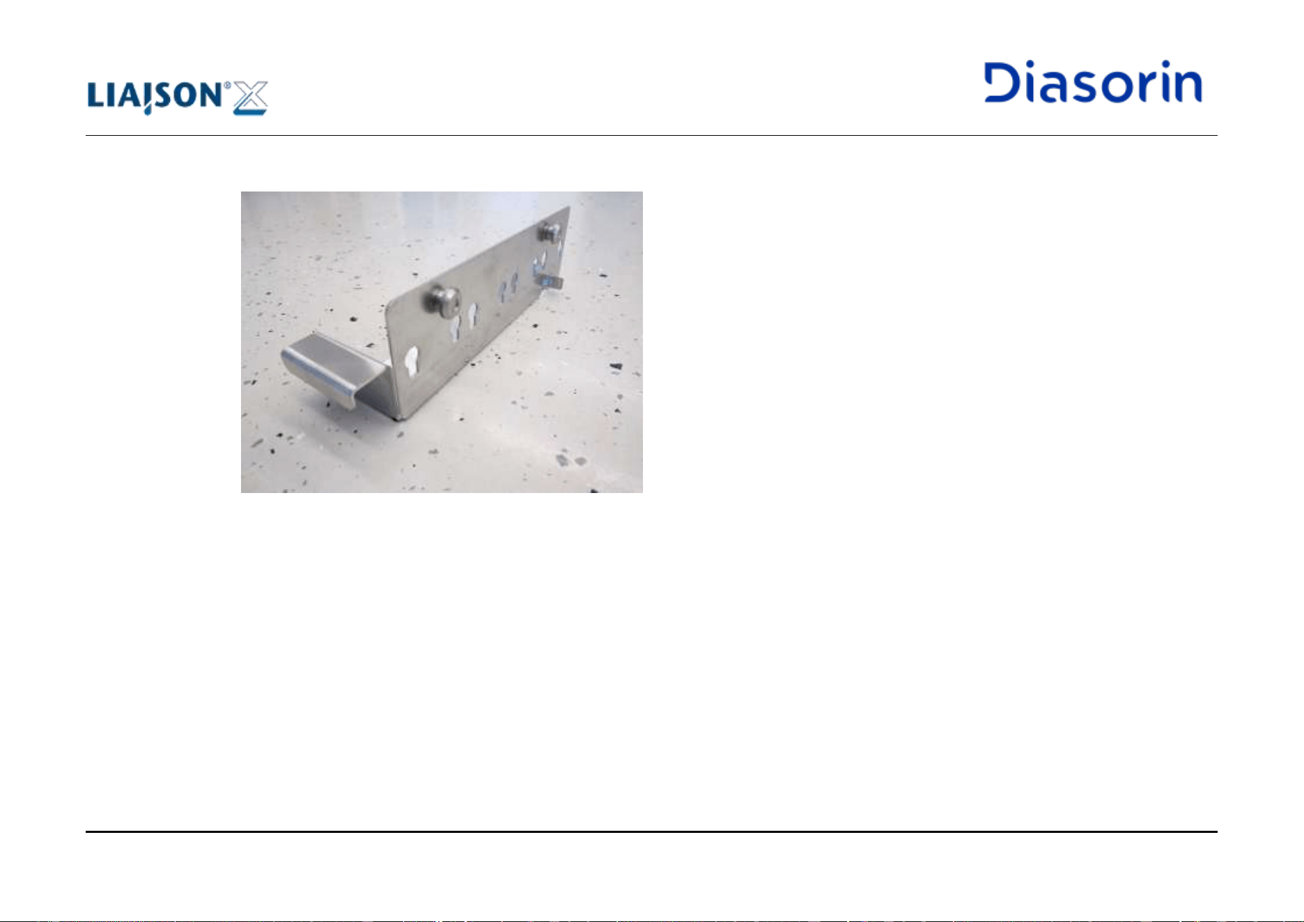
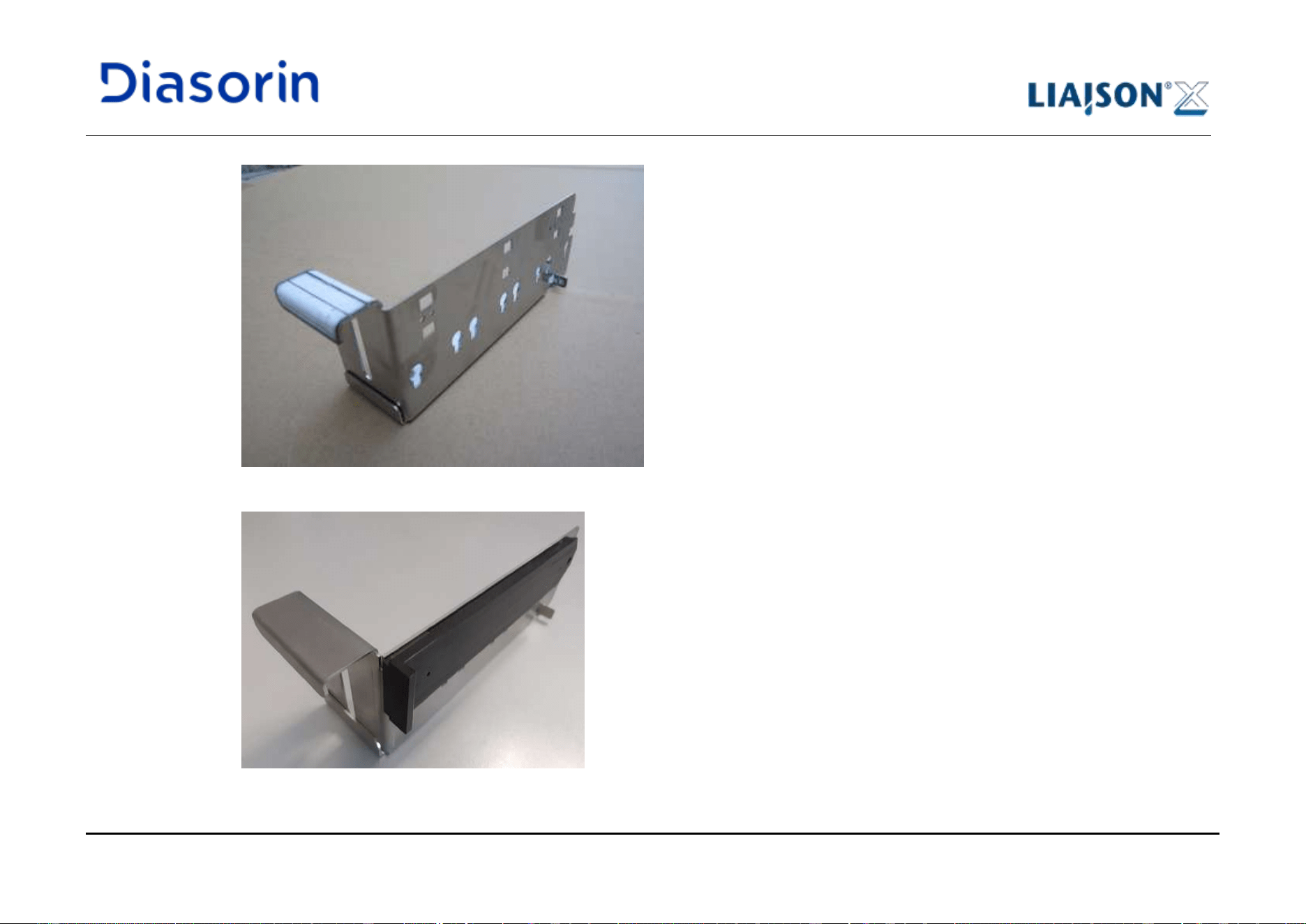
4 System Description
Page 4-38 LIAISON XL - Instructions for use
Rev. L
There is no functional difference between the different types of ancillary racks. Nevertheless, due to geometric
considerations, ancillary racks with increased front wall are not compatible with loading bays designed for ancillary
racks with short front wall and viceversa.
The information included in the integral or ancillary reagent (RFID label) is read and used in the LIAISON
®
XL software.
The loading bay for reagents is cooled during the complete operation (incl. stand-by mode). The liquid inside the integrals and ancillary
reagents are cooled to 13 °C ±2 °C.
To avoid temperature errors of the reagent loading bay, it should be opened only briefly for loading and unloading.
The system will beep to remind to close the reagent bay flap.
A LED below each lane indicates the current usage status when the flap is open, while the status “slow flashing” is not shown with the flap
closed:
Description
Status
Action
The integral or ancillary reagents are currently being used or
scheduled for a test.
LED ON
Do not remove it.
The integral or Ancillary reagents are not used or scheduled.
LED OFF
It is possible to remove it.
The lane is activated, and can be used to load an integral or the
ancillary rack.
LED slow flashing
(once per second)
It is possible to insert an
integral or the ancillary
rack into this lane.
The integral or ancillary reagents have not been recognized.
LED fast flashing
(three times per second)
Remove the integral and
insert it again.
Table 4-5: LEDs on the loading bay for reagents
LEDs
4 System Description
LIAISON XL - Instructions for use Page 4-39
Rev. L
4.2.6.1 External Reagents
DiaSorin external reagents are delivered in vials separated from the integral, for example lyophilized kit reagents, or Light Check for
troubleshooting.
These vials are of appropriate dimensions made to fit dedicated adaptors for the ancillary rack. This is the only rack type to be used for these
vials.
External kit reagents, that shall be used as part of a test routine, are provided mounted on a specific non removable adaptor. Reagents like
Light Check, that are not to be used as part of a regular test routine, are to be inserted into adaptors provided with the instrument.
The information included in the reagent (RFID label) is read from the system and used in the LIAISON
®
XL software.
4.2.7 Integrated re-suspension tool
The integrated re-suspension tool is a solid state magnetic device which aids in the dispersal of microparticles prior to placement of a
LIAISON
®
XL reagent integral on the LIAISON
®
XL system.
For a LIAISON
®
XL reagent integral to perform as intended, the microparticles must be completely and homogeneously re-suspended.
The integrated tool is designed to assist in the preparation of the reagent integral by magnetically drawing the paramagnetic microparticles
away from the bottom of the reagent integral microparticle vial. With subsequent agitation of the vial automatically performed by the instrument
over a 15 minutes time span, the operator is ensured of a properly prepared reagent integral.
4.2.7.1 Use of the integrated re-suspension tool
1. Slide the reagent integral into the slot until it is fully engaged;
2. Allow the reagent integral to remain in the tool for at least 30 seconds;
3. Remove the integral and inspect for the presence of particles at the bottom of the vial: if microparticles are still present at the bottom,
repeat procedure as many times as needed to have a complete removal;
4. After a complete removal of particles from the bottom of the vial has been achieved, insert the integral in an available slot in the
reagent area and let it agitate for 15 minutes before starting a run.
4 System Description
Page 4-40 LIAISON XL - Instructions for use
Rev. L
4.2.8 Area for Starter Reagents
The area for starter reagents contains the starter reagents (LIAISON
®
XL Starter Kit or LIAISON
®
EASY Starter Kit). The starter reagent
bottles are provided with removable screw caps that are to be removed to allow the insertion of the dedicated tubing. Correct emplacement is
ensured by a clamp holding on a reset on the bottle neck. A RFID in the back of the bottle identifies starter reagents and tracks consumption.
Since the starter reagents are light sensitive, the flap of the area must always be closed.
To prevent confusion, the information included in the starter reagent (RFID label) is read from the system and used in the LIAISON
®
XL
software.
To allow continuous exchange, each position contains one LED which indicates the relevant usage status (see below).
Please read the instructions for use (IFU) concerning the starter reagents (LIAISON
®
XL Starter Kit or LIAISON
®
EASY Starter Kit).
Always keep the starter reagent area closed to avoid light.
An LED indicates for each position the current usage status when the flap is open, while the status “slow flashing” is not shown with the flap
closed:
Description
Status
Action
The starter reagent is currently ready to be used for a test.
LED ON
Do not remove it.
The loaded starter reagent is not used or scheduled.
LED OFF
It is possible to remove it.
The lane is activated, and can be used to load a starter bottle.
LED slow flashing (once
per second)
Insert a starter reagent at
this position.
The starter reagent has not been recognized or it is the wrong type.
LED fast flashing
(three times per second)
Remove the starter
reagent completely and
insert it again.
Table 4-6: LEDs on the area for starter reagents
LEDs
4 System Description
LIAISON XL - Instructions for use Page 4-41
Rev. L
4.2.9 Cabinet
All large-volume containers for the liquid supply and disposal are located in the cabinet. In addition, there is a container with a foil bag for the
solid waste and a bottle for routine cleaning of the system lines. Some additional devices (waste basin, waste bin) are used to increase safety
in the handling of contaminated materials.
4.2.9.1 Water
The water container together with a docking container allows the refilling of water without interruption of the operation of the LIAISON
®
XL.
A sensor hereby controls the current liquid level and requests the user to refill water at a certain residual volume. For refilling, the user
removes the water container (10 L) and returns it to its original position after refilling. A corresponding docking connector provides the leak
proof connection between the two containers.
In case LIAISON
®
diluteX is connected to the analyzer, is is not necessary to refill the water container, since the LIAISON
®
diluteX
automatically refills it. For further details, please refer to LIAISON
®
diluteX User Manual.
4.2.9.2 Wash buffer
The wash buffer container together with a docking container allows the refilling of wash buffer without interruption of the operation of the
LIAISON
®
XL. A sensor hereby controls the current liquid level and requests the user to refill wash buffer at a certain residual volume.
For refilling, the user removes the wash buffer container (10 L) and returns it to its original position after refilling. A corresponding docking
connector provides the leak proof connection between the two containers.
In case LIAISON
®
diluteX is connected to the analyzer, is is not necessary to refill the wash buffer container, since the LIAISON
®
diluteX
automatically refills it. For further details, please refer to LIAISON
®
diluteX User Manual.
4.2.9.3 Cleaning solution
The cleaning solution container has a volume of 2 liters. Level in bottle is not tracked by the system. The user must ensure that enough liquid
is present for required task before starting a maintenance routine.
4 System Description
Page 4-42 LIAISON XL - Instructions for use
Rev. L
4.2.9.4 Liquid waste
See Biological safety in chapter 1.8.6.
To allow a continuous operation of the LIAISON
®
XL, the system is provided with two independent liquid waste containers (2x10 L). As soon
as one of the two containers is full, the system automatically switches to the second container and the user is requested to empty the relevant
container. At the container itself, there is an LED indicating the usage status (see below).
LED Status
Description
Action
ON
The container is currently being used or
scheduled for a test.
Do not remove it.
OFF
The container is not used or scheduled.
It is possible to remove it.
Table 4-7: LEDs on the waste containers
4.2.9.5 Waste basin
A waste basin is placed in the cabinet of the instrument to host waste tanks. This solution is used to avoid a potential contamination of the
cabinet caused by spillage of contaminated liquid from a broken waste tank.
Refer to chapter 1.10.7 for labelling and chapter 5.5.6.3 for removal procedures.
LEDs
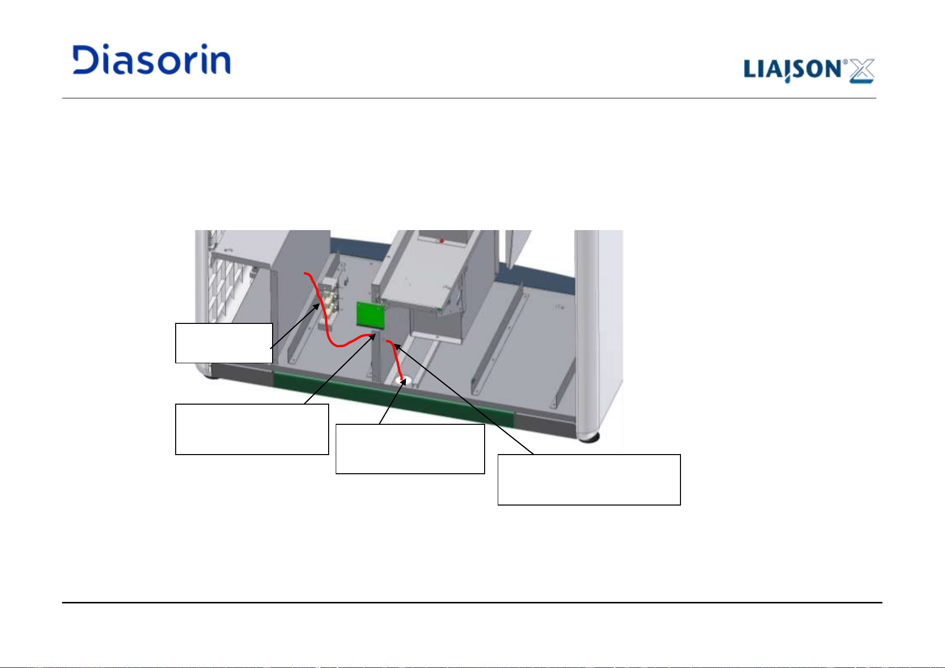
4 System Description
LIAISON XL - Instructions for use Page 4-43
Rev. L
4.2.9.6 Direct drain configuration
LIAISON
®
XL system supports also a direct drain configuration, where a waste tube can be directly connected to the system allowing to
dispose liquid waste directly into a collector drain. In this case liquid waste containers and basin shall not be installed in the instrument.
Direct drain is an optional solution, all systems are shipped with waste containers. In case of specific request of the users, direct drain
configuration can be implemented by field service engineers during the installation of the instrument or at a later point in time.
Figure 4-25: Direct drain connection, back view
Hole in the Cabinet Floor:
tube goes through and out
of the system.
Tubing from the
instrument
Drill hole in the separation
sheet metal, position of
tube fitting with strain relief
From the separation panel
onwards, the tubing is covered
by a protection conduit.
4 System Description
Page 4-44 LIAISON XL - Instructions for use
Rev. L
Direct Drain Installation
Please note that the direct drain configuration may only be installed by authorized service personnel.
The length of the direct drain tubing can reach up to 10 meters, contact the local service support for more information.
Do not modify the direct drain configuration installed by the service technicians
4.2.9.7 Solid waste drawer
Next to the liquid waste containers, there is a drawer for solid waste (cuvettes and disposable tips) accumulated in the LIAISON
®
XL system.
To simplify disposal, and contain biological hazards, the container is provided with a foil bag.
To allow continuous operation during the exchange of the foil bag, the system is provided with an additional container. In this additional
container, the accumulating solid waste is collected during the replacement of the foil bag and put into the solid waste drawer automatically
upon reclosing the solid waste drawer. The filling level of both containers is controlled by the LIAISON
®
XL software.
4.2.9.8 Solid waste bin
In order to increase the safety during waste bag disposal, a solid waste bin can be placed in the dedicated drawer of the cabinet, in order to
host the waste bag. The available handles allow the user to remove and reinsert it into the waste drawer, thus avoiding any contact with the
bag during the disposal phase.
Refer to chapter 1.10.6 for labelling and chapter 5.5.7 for use.
4 System Description
LIAISON XL - Instructions for use Page 4-45
Rev. L
4.2.10 Incubator
In addition to heating, the incubator includes a conveyor belt for the transport of up to 80 cuvettes. The conveyor belt moves every single
cuvette to various positions (washer or pipetting positions) when needed.
The working temperature range (36.5 °C – 38.5 °C) is reached at the latest after a heating time of 1 hour. If the temperature falls below or
exceeds the expected range value during operation, a warning is issued.
The current temperature of the incubator can be found in the LIAISON
®
XL software in the main category Status sub category Temperatures
(see chapter 6.10.3).
4.2.11 Pipettors
The LIAISON
®
XL system is provided with two independent pipettors to distribute samples and reagents throughout the testing processes.
The two pipettors can aspirate variable liquid volumes of samples or reagents and dispense them into the cuvettes in the incubator.
A pipettor working with disposable tips aspirates liquid from a specified sample, control or external calibrator and dispenses it into a cuvette.
The LIAISON
®
XL software associates the dispensed sample and the test to be processed to the cuvette.
This pipettor, located on the left side of the system, can only reach the loading bay for samples during a test routine, and additionally the
ancillary area in the loading bay for reagents during a maintenance routine.
Additionally, the sample pipettor allows the transferal of liquid from one cuvette to another in order to perform sample pre-dilutions.The use of
disposable tips prevents cross-contamination between samples, controls or external calibrators.
A stainless steel probe pipettor aspirates liquid from one or more reagent vials (integral or ancillary reagent) and dispenses it into a cuvette.
The inside and outside of the steel probe is cleaned in the wash station after the process step, in such a way as to prevent cross-
contamination between different reagents..
To ensure the correct take-up of liquid, both pipettors are provided with a liquid level detection system and volume aspiration and dispensing
monitoring. The combination of the two allows for the aspiration of liquid(s) from the appropriate position and for the control of the accuracy of
the dispensation. Additionally, the left pipettor can detect whether there are clots in a sample.
Sample Pipettor
Reagent Pipettor
Checks
4 System Description
Page 4-46 LIAISON XL - Instructions for use
Rev. L
4.2.12 Washer
In the washer, several cuvettes can be processed at the same time. Cuvettes in the washer can be transported either back to the incubator or into
the reader after processing, according to the sequence of the requested assay. The washer needles are rinsed after every aspiration cycle.
4.2.13 Reader
The dispensing of the two starter reagents and the chemiluminescence measurement are carried out in the reader, equipped with a high
sensitivity photomultiplier. The reader is sealed from all outside light influences. The two independently controlled injection pumps for injection of
the starter reagents are placed outside the reader: each of them operates with a constant volume of 200 µL to inject starter reagents into the
cuvette. One injection of each of the two starter reagents (starter 1 and starter 2) is needed in order to develop the chemiluminescent reaction.
The geometrical arrangement of the injectors in the Reader ensures that the injection of starter 1 is directed against the wall of the cuvette.
Starter 2 is injected straight into the cuvette. This ensures optimum re-suspension of the magnetic particles. After each individual
measurement and before cuvette disposing, the reaction solution is drawn from the cuvette by an aspiration needle. Once completed this
operation, the cuvette is then disposed off into the waste bag.
4.2.14 Visual Alarm
On top of the LIAISON
®
XL system a visual alarm system may be installed as an option.
The visual alarm system shall provide the user with visual warnings of the system functionality over short distances. It shows a visual signal
about fatal and system errors.
The mute and auto-mute functionality for the beeper also turn off the visual alarm.
4.2.15 Printer
An USB printer can be connected to the Analyzer by authorized DiaSorin service personnel; a dedicated support can be added to the right
side of the instrument, in order to allow a proper placing of the printer. Both local and network printers are supported; the printer connected to
the Analyzer shall be set as “default printer”.
Print only hard copies. Never change the destination printer.
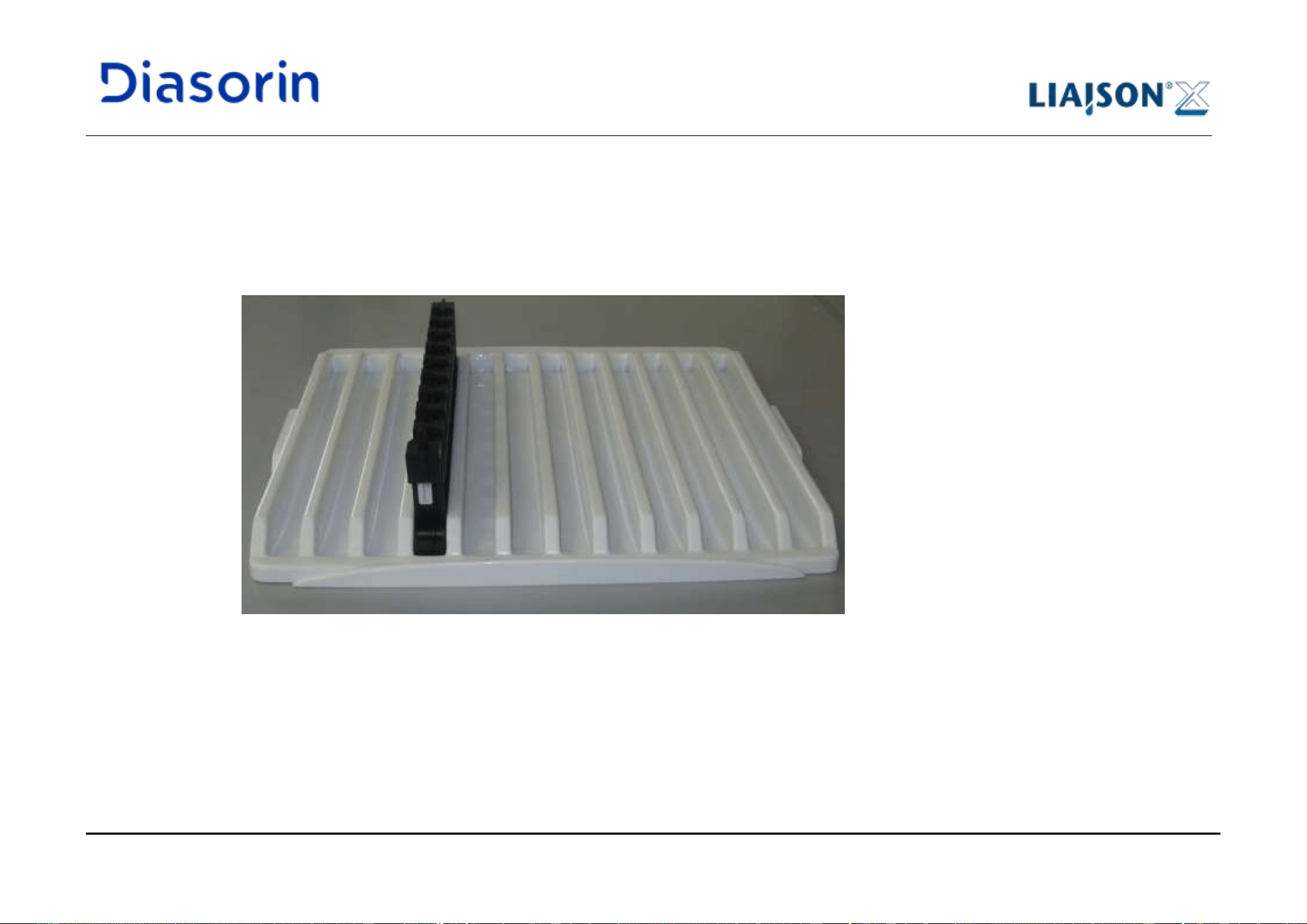
4 System Description
LIAISON XL - Instructions for use Page 4-47
Rev. L
4.2.16 Holders
4.2.16.1 Rack Holder
A dedicated holder (Figure 4-26) is available for handling of sample and control racks outside the instrument. Up to 12 racks can be
transported at the same time using this holder.
Figure 4-26: Rack holder with equipped racks
4.2.16.2 Integral Holder
A dedicated holder is available for handling of reagent kits outside the instrument. Up to 16 kits can be transported at the same time using this
holder; dedicated positions are available to host kits composed by 2 integrals.
4 System Description
Page 4-48 LIAISON XL - Instructions for use
Rev. L
4.3 Accessories and Consumables
In order to facilitate tests requested by the user, the instrument requires the following:
Cuvettes – Vessels in which the immuno-chemical reaction between the sample and reagents occurs. The measurement of the immuno-
chemical reaction is also achieved in these vessels.
Disposable Tips – The vessels used to transport sample from the laboratory container to the cuvette.
Samples – Liquids obtained from patients in the form of blood, serum, plasma, or urine necessary for determining the results of a certain test
for a certain patient.
Reagents – Groups of biological or chemical agents scientifically combined to assess a certain status of a sickness or disease of a given
patient.
LIAISON
®
diluteX is an optional accessory of the LIAISON
®
XL and LIAISON
®
XL Workcell Upgrade Kit for the provision of the Wash Buffer
and the purified water to the analyzer. Please refer to LIAISON
®
diluteX User Manual for details. The availability of LIAISON
®
diluteX
depends upon specific market regulations. Please refer to your local Diasorin Representative for details on availabilty.
These above listed items must be added by the user as pertaining to the respective tests and the amount of tests wanted.
Use only the consumables and accessories described herein and approved by
DiaSorin Italia S.p.A.
The Instructions for use for accessories and of consumables are provided for user safety and give important
instructions for the handling. The IFU for the consumables can be found in the appendix of this manual.
See chapter 5.5 and chapter 5.7 for the use of accessories and consumables.
5 Use of the System
LIAISON XL - Instructions for use Page 5-1
Rev. L
5 Use of the System
Conditioning time
The system requires 1 hour for temperature conditioning of the incubator and the reagent loading bay.
In this chapter, the processing of a test from switching on the system to switching off the system for a "normal" user is described in regards to
starting a worklist.
All functions of the LIAISON
®
XL software are described in chapter 6.
5.1 Safety and Hints
See chapter 1.8 for all safety hazards.
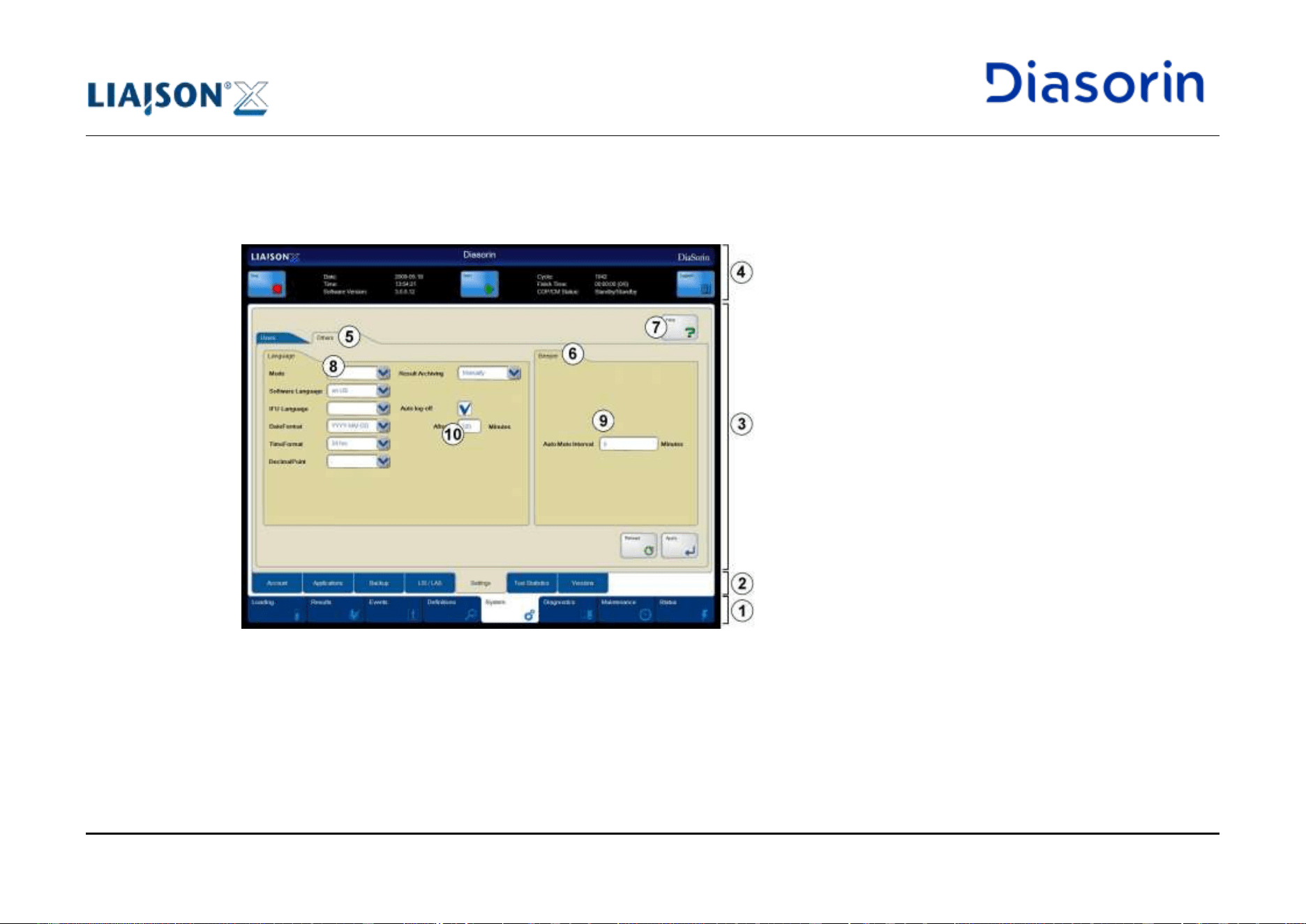
5 Use of the System
LIAISON XL - Instructions for use Page 5-3
Rev. L
1
Main categories:
Click on the respective tab to change the main category.
Example: Click on the System main category tab.
2
Sub categories:
Click on the respective tab to show details of the sub category in the sub category display.
Example: Click on the Settings sub category tab.
3
Display:
Shows all details of the selected sub category.
Example: The system shows all functions on the Settings sub category display.
4
Header:
Shows information about the system and contains the Stop, Start and Support buttons.
Example: The system status is shown on the Header.
5
Tabs:
Subdivides a sub category into different areas.
Example: Click on the Others tab.
6
Groups:
Combines functions to groups.
Example: All functions are shown in the Language group.
7
Buttons:
Click on the respective button to start a special function.
Example: Click on the Apply button.
8
Selection boxes:
Click on the arrow and select one of the shown entries.
Example: Select the YYYY-MM-DD entry of the DateFormat selection box.
5 Use of the System
Page 5-4 LIAISON XL - Instructions for use
Rev. L
9
Checkboxes:
Click on the square or circle box to activate a function or option.
A checkmark in a square box of a checkbox shows an activated function/option.
A point in a radio button shows an activated function/option. These types of radio buttons are organized in
groups. Only one radio button for each group can be activated.
Example: Activate the Auto log-off checkbox.
10
Input boxes:
Use the on screen keyboard to write into an input box. See also section Tooltips below.
Example: Enter the new value in the Minutes box.
-
Tooltips:
Tooltips are used to inform the user about wrong values in input boxes. After entering the correct value, the
tooltips disappear. The tooltips disappear also automatically few seconds after their appearance.
LEDs and signal
lamps
Describes LEDs (light emitting diode) and signal lamps of the instrument.
Example: The
Lane
LED of the sample loading bay will illuminate.
Keys
Describes special keys of the on screen keyboard.
Example: Press on the Enter key to confirm the entry.
Drives, folders,
and files
Describes special drives (hard disks, USB sticks) of the computer or special folders and files on the
computer.
Example: Choose D:\LiaisonXL\Share as backup path.
Prescribed
parameters
Describes special parameters or values to enter into an input box.
Example: Enter 10 into the shown input box.
Miscellaneous
5 Use of the System
LIAISON XL - Instructions for use Page 5-5
Rev. L
5.3 Daily activities plan
Start-up
• Switch-on (only if off)
• Log-on
• Respect the conditioning time
chapter 5.4
Check
• Check cuvettes, disposable tips, starter reagents and liquid
containers
chapter 5.5
Load Integrals and Ancillary reagents
• Load integrals
• Load ancillary reagents
chapter 5.7
Load Controls and Calibrators
• Load controls
• Load calibrators
chapter 5.7
Calibrate integrals
• Calibrate integrals
chapter 5.7
Load Samples and Assign Assays
• Load patient samples
• Assign assays to the patient samples
chapter 5.6
Start Worklist
• Start the run
chapter 5.8
Results
• Check results
chapter 5.9
Errors and Events
• Check errors and events
chapter 5.9.5
Unloading
• Unload unused sample racks
• Unload unused integrals
chapter 5.11
Shut Down/End of Day Maintenance
• No special care
• If planned for today, perform periodical maintenance
chapters 5.12 and 6.9
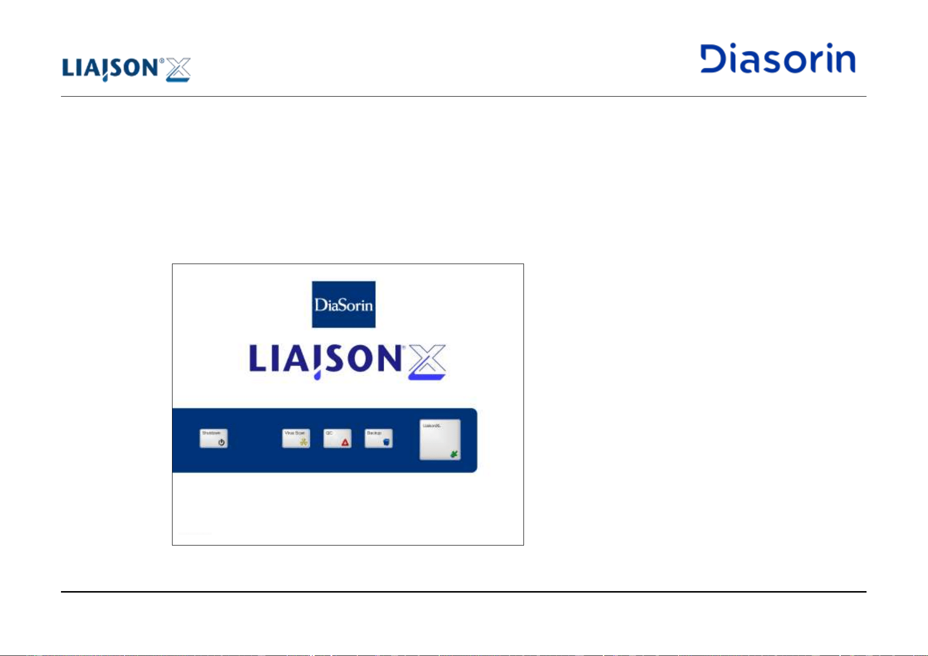
5 Use of the System
Page 5-6 LIAISON XL - Instructions for use
Rev. L
5.4 Start-up
Switch on and log-on:
1. Ensure that the cover and the flaps are closed.
2. Switch on the instrument.
3. Switch on the integrated PC.
The system starts the operating system and the LIAISON
®
XL software on the integrated PC.
4. After system start, the LIAISON
®
XL software shows the Startup display:
Figure 5-2: Startup screen
Procedure
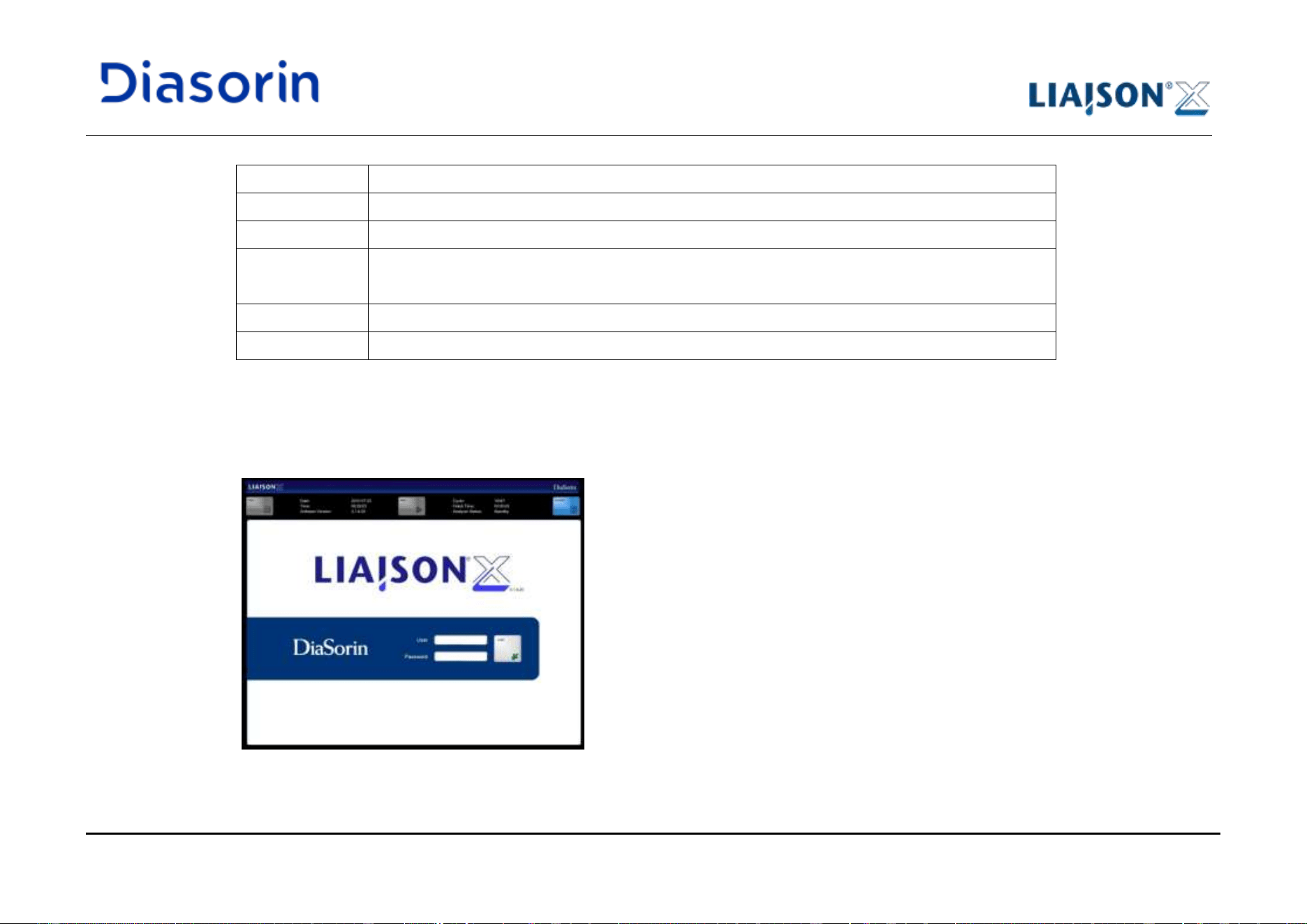
5 Use of the System
LIAISON XL - Instructions for use Page 5-7
Rev. L
Function
Description
Backup
Starts the external backup viewer application (see chapter 6.11).
LiaisonXL
Starts the LIAISON
®
XL software (see below).
QC
Starts the long term quality control (QC) application (see chapter 1).
Note: if installed, the QC software V2 is started.
Shutdown
Shut the PC system software and switch off the computer.
Virus Scan
Starts the virus scan software. In case a virus is reported, please contact local support.
Table 5-1: Functions of the Applications sub category
5. Click on the LiaisonXL button.
The LIAISON
®
XL software shows the Login display:
Figure 5-3: Login
5 Use of the System
Page 5-8 LIAISON XL - Instructions for use
Rev. L
There are several security levels of user access rights on the LIAISON
®
XL system. Some system functions are only
available for users with an appropriate access level (e.g. changing system options, or setting user accounts).
The system may spontaneously require to perform an automated back-up of temporary files upon pressing the
LiaisonXL button. This action will take few minutes, and will improve the PC performance. Please confirm the related
pop-up when prompted.
6. Enter the user name into the User box.
The user name is not case sensitive.
7. Enter the appropriate password into the Password box.
The password is case sensitive.
8. Click on the Login button.
9. From the STOP menu, initialize the system (see chapter 6.2.1).
The LIAISON
®
XL software initializes the instrument and shows the Loading Samples display.
Conditioning time:
10. Wait for 1 hour. The system requires 1 hour for temperature conditioning of the incubator and the reagent loading bay.
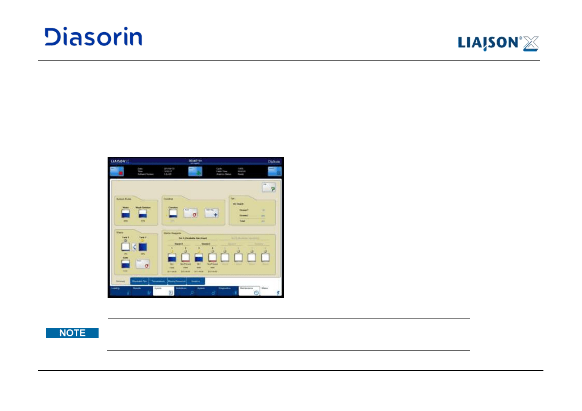
5 Use of the System
LIAISON XL - Instructions for use Page 5-9
Rev. L
5.5 Check Cuvettes, Disposable Tips, Starter Reagents and Liquid Containers
At the beginning of each run, the filling level of the liquid containers and the starter reagents must be checked, as well as sufficient cuvettes
and disposable tips available in the instrument.
1. Click on the Status main category tab.
2. Click on the Summary sub category tab.
Figure 5-4: Sub category Summary
It is possible to compare the indicated conditions with the actual filling levels in the relevant containers, bottles and
solid waste. If the indicated and actual filling levels are not concordant with each other, a service engineer should be
contacted if required.
Procedure
5 Use of the System
Page 5-10 LIAISON XL - Instructions for use
Rev. L
(blue)
(yellow)
(red)
Other possible status
Additional information
Water
at least 30%
in range 13%-30%
running out
(less than 13%)
Disconnected
"Active" tests are not counted.
Wash Buffer
at least 30%
in range 12%-30%
running out
(less than 12%)
Disconnected
"Active" tests are not counted.
Starter
at least
80 injections
less than
80 injections
running out
(0,1,2 injections)
Absent (bottle not loaded)
Present (bottle not primed)
Not Available (bottle empty
or offline)
Thresholds are compared with
the difference between number
of available shots and "active"
tests. Red is reached when this
difference is 0.
Cuvettes
cuvettes are
detected by
sensors
cuvette buffer is
empty
running out (less
than 3 cuvettes
detected)
Based on sensors detection
Solid Waste
(cuvettes/tips)
no more than
1700
in range 1700-
2000
nearly full (more
than 2000)
Pulled Out
"Active" tests are not counted for
yellow status.
Red threshold is compared with
the sum of number of cuvettes
(tips) in waste drawer and
"active" tests.
When pulled out, there is space
for no more than 50.
Liquid Waste
no more than 70%
in range 70-84%
nearly full (more
than 84% liquid)
Absent (tank not loaded)
Thresholds are referred to the
total amount of the two tanks.
"Active" tests are not counted.
Table 5-2: Used colour code
5 Use of the System
LIAISON XL - Instructions for use Page 5-11
Rev. L
Symbol
Meaning
Container connected and active
Container connected and inactive
Container not connected
Table 5-3: Used symbols
Shows the usable volume of the Water and the Wash Solution containers [in percent].
Notice the System Fluids group:
3. Check the levels of both system fluids containers (Water and Wash Solution). If low, refill them.
Table 5-4: Functions of the Cuvettes group
Notice the Cuvettes group:
4. Check the number of the cuvettes. If low, refill them.
Refill procedure: see chapter 5.5.1.
System Fluids
Group
Cuvettes Group
Function
Description
Added Bag
Press on this button after refilling of cuvettes. The Cuvettes
counter incremented about 200.
(1 cuvettes bag = 200 cuvettes)
Cuvettes
Shows the number of cuvettes in the instrument.
Reset
Press on this button to set the Cuvettes counter to 0.
5 Use of the System
Page 5-12 LIAISON XL - Instructions for use
Rev. L
Shows the number of unused disposable tips in the instrument.
Notice the Tips group:
5. Check the number of the disposable tips in both drawers. If low, refill them.
Refill procedure, see chapter 5.5.2.
Shows the filling level of the liquid waste containers (Tank 1 and Tank2) in per cent, and Solid waste (cuvettes and disposable tips).
Function
Description
Reset
Pressing on this button clears the counter for solid waste. The
procedure is due upon empting of the solid waste reservoir
or
Changes the used waste tank:
• Tank 1 > Tank2: Changes tank in use: from Tank 1 to
Tank 2
• Tank 1 < Tank2: Changes tank in use: from Tank 2 to
Tank 1
Table 5-5: Functions of the Waste group
See chapter 1.8.6 for Biological Safety.
Tips Group
Waste Group
5 Use of the System
LIAISON XL - Instructions for use Page 5-13
Rev. L
Notice the Waste group:
6. Check the levels of both waste liquid containers (Tank 1 and Tank2). If full or nearly full, empty and decontaminate it.
7. Check the level of the Solid waste container. If full or nearly full, empty it. After that, click on the Reset button.
Shows remaining injection counters of all loaded starter reagents. The counter decreases after every injection.
Notice the Starter Reagents group:
8. Check the levels of the starter reagent bottles. If low, load a new bottle.
The information is reported only when the starters after correctly primed by the system.
Starter Reagents
Group
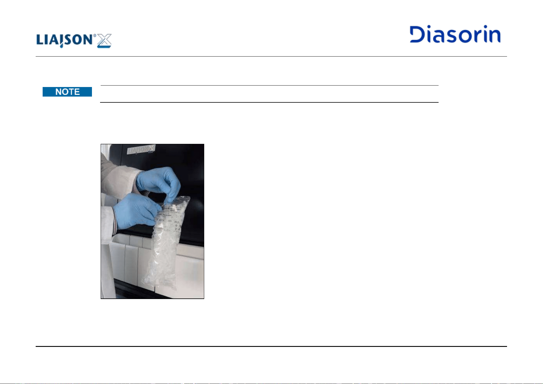
5 Use of the System
Page 5-14 LIAISON XL - Instructions for use
Rev. L
5.5.1 Refill cuvettes
Before starting the handling procedure, consult Instruction for Use (IFU) for cuvettes.
1. Holding the cuvette pack so that the perforated end is upright, ensure that all cuvettes in the bag are below the perforated mark.
2. Using one hand to hold the pack under the perforated mark, remove the upper end of the cuvette pack (Figure 5-5) and immediately
discard the separated piece.
Figure 5-5: Opening the cuvette pack
3. Open the cuvette loading access door on the analyzer.
Procedure
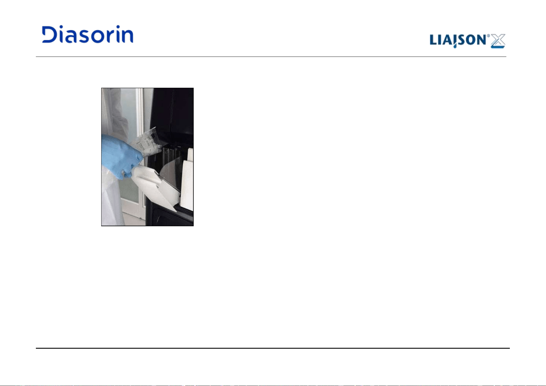
5 Use of the System
LIAISON XL - Instructions for use Page 5-15
Rev. L
4. Continuing to hold the cuvette pack in an upright position, place the cuvette pack directly over the cuvette loading access and slowly
empty the complete contents of the cuvette pack into the loading access (Figure 5-6)
Figure 5-6: Loading the cuvette pack
5. Once the loading has been completed, close the cuvette loading access door and discard the cuvette pack.
6. Select the sub-category Summary of the category Status (refer to chapter 6.10.1). Press Added bag button corresponding to the number
of packs loaded.
5 Use of the System
Page 5-16 LIAISON XL - Instructions for use
Rev. L
Always load the complete cuvette bag into the analyzer.
Press the button only once for each bag loaded.
Cuvettes are for single use only.
During the loading of cuvettes, verify not to exceed the maximum tolerated level, indicated by the red line available
on the cuvette reservoir (see chapter 1.10.16).
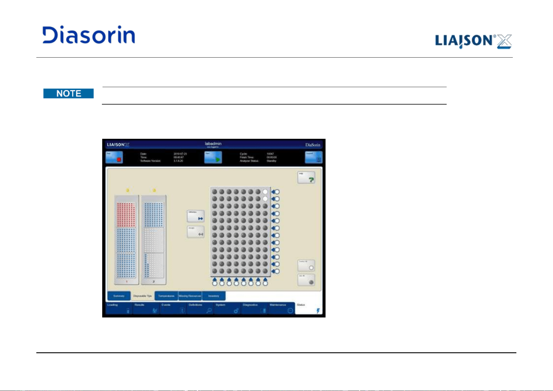
5 Use of the System
LIAISON XL - Instructions for use Page 5-17
Rev. L
5.5.2 Refill Disposable Tips
Before starting the handling procedure, consult Instruction for Use (IFU) for Disposable Tips.
1. Click on the Status main category tab.
2. Click on the Disposable Tips sub category tab.
Figure 5-7: Sub category Disposable Tips
Procedure
5 Use of the System
Page 5-18 LIAISON XL - Instructions for use
Rev. L
Function
Description
Assign
Gives the access of the drawer to the pipettor system. The LED
below the drawer on the system and the indicator above the
drawer in the software display change to yellow.
The Assign button is only available when the drawer is closed.
Delete All
Deletes all disposable tips on the single disposable tip tray.
Set All
Fills the single disposable tip tray with disposable tips.
Withdraw
Gives the access of the drawer to the user. The LED below the
drawer on the system and the indicator above the drawer in the
software display change to grey.
Note: If the instrument is pipetting, the pipettor will use the other
drawer. If the LED does not turn grey, the drawer cannot be
released by the system. If the drawer contains no tips, the drawer
is automatically withdrawn.
Standard buttons
For standard buttons (e.g. arrow buttons, lock, Print)
see chapter 6.1.
Table 5-6: Functions of the Disposable Tips sub category
3. Click on the disposable tip tray position of drawer 1 or 2.
4. Click on the Withdraw button.
The LED below the drawer on the system is flashing off and the indicator above the drawer on the software display changes to grey.
If the system is pipetting, the pipettor will use the other drawer. If the LED does not turn grey, the drawer cannot be
released by the system. If the drawer contains no tips, the drawer is automatically withdrawn.
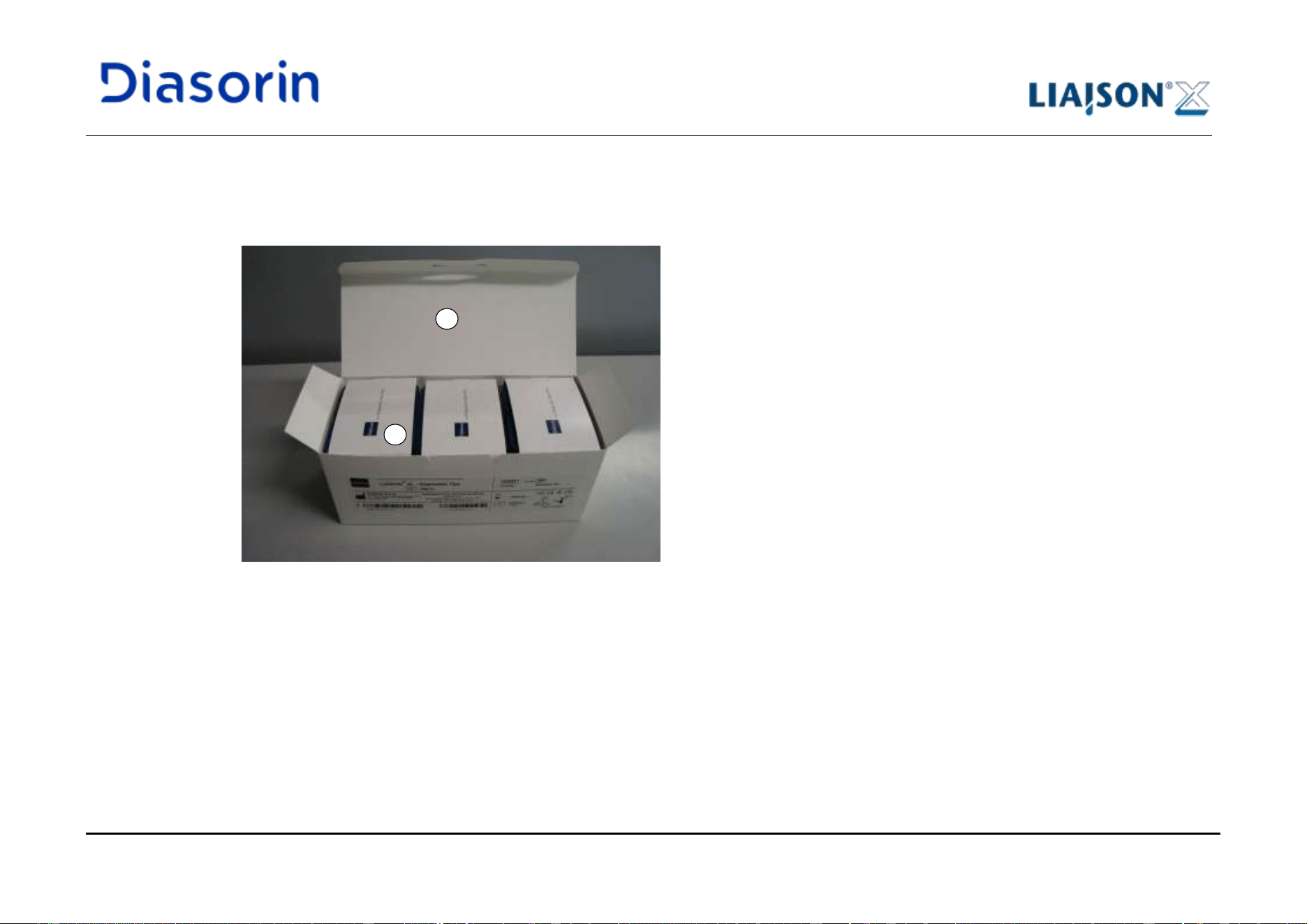
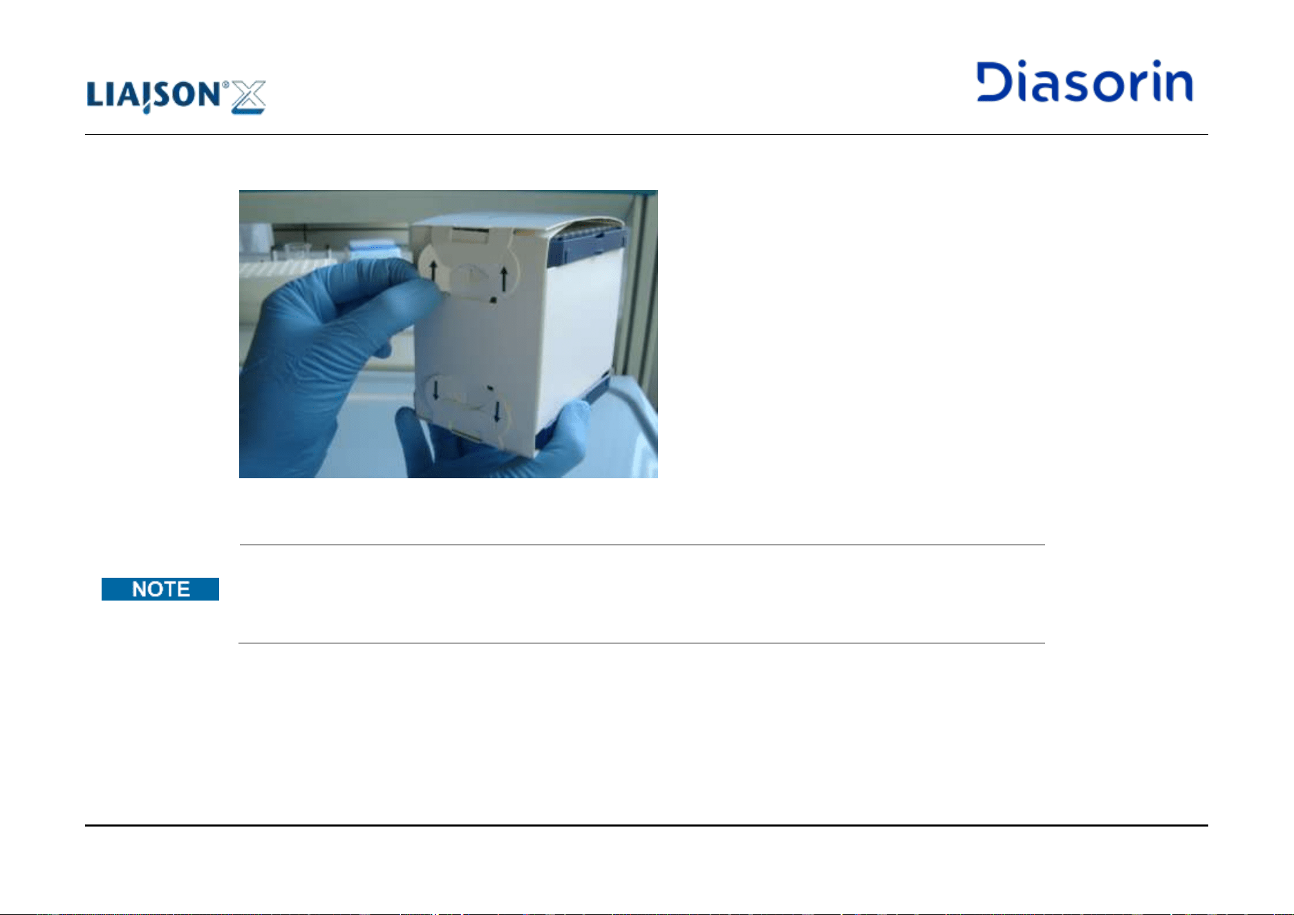
5 Use of the System
Page 5-20 LIAISON XL - Instructions for use
Rev. L
8. Open one side of the folding sleeve by pulling up one of the available flaps (as indicated by the arrow symbols).
Figure 5-9: Folding sleeve opening
The LIAISON
®
XL Disposable Tip/ LIAISON
®
Disposable Tip user box may be opened only from one side. Each user
box contains 3 folding sleeves.
Each folding sleeve contains 2 trays and may be opened from either the top or the bottom sides. Each opening gives
the user access to 1 tray. Only one of the openings can be opened at a time.
9. Using one hand, take a disposable tip tray by holding it on the longer side and insert it into the disposable tip drawer on the analyzer.
10. If necessary, repeat points 7-9 until all positions of the drawer have been loaded.
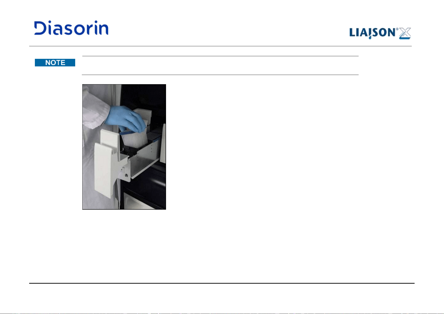
5 Use of the System
LIAISON XL - Instructions for use Page 5-21
Rev. L
Insertion of partially filled tip trays is possible; in this case, it is necessary to pay attention to the tip placement and to
indicate their placement on the software interface in next steps.
Figure 5-10: Loading the tip tray
11. Close the opened drawer.
Note: this step may be performed even afterwards, before pressing the Assign button.
12. Click on the Set All button.
13. If more than one tray has been loaded in the selected drawer, click on the next refilled disposable tip tray position of the selected drawer
and click on the Set All button, too.
5 Use of the System
Page 5-22 LIAISON XL - Instructions for use
Rev. L
14. When ready, click on the Assign button.
The LED below the drawer is permanently illuminated and the indicator above the drawer on the display changes to yellow. The pipettor
has access to the drawer. From now on, to remove the drawer it is necessary to repeat this procedure from step 1, regardless if the
system is running or not.
All disposable tips are for single use only.
5.5.3 Load and Unload Starter
The starter reagents also include 4% sodium hydroxide and a 0.12% peroxide solution. If splashes of the NaOH
solution or the alkaline peroxide solution get into eye, immediate and thorough washing with water or a suitable buffer
solution is recommended. If necessary, a physician should be consulted.
Starter pooling is prohibited!
Refer to the safety notes (see chapter 5.7)!
The LIAISON
®
XL Starter Kit or LIAISON
®
EASY Starter Kit should be kept away from direct sunlight.
Please comply with the storage and shelf life information for the starter reagents (LIAISON
®
XL Starter Kit or LIAISON
®
EASY Starter Kit).
5 Use of the System
LIAISON XL - Instructions for use Page 5-23
Rev. L
1. Open the flap for starter reagents.
2. The LED below the empty starter reagent bottle must be off.
If the LED is slow flashing, there is no starter reagent bottle.
Remove the cap of the empty starter reagent bottle.
3. Remove the empty starter reagent bottle.
1. Remove the locking cap of the new starter reagent bottle.
2. Place the LIAISON
®
XL system cap onto the new starter reagent bottle.
It is essential to ensure correct connection to starter 1 and starter 2.
3. Insert the new starter reagent bottle into the LIAISON
®
XL system.
4. If the LED below starts flashing fast (three times per second), the starter reagent bottle has not been recognized or it is the wrong starter
type.
5. If point 4 has been verified, remove the starter reagent bottle completely and re-insert it.
6. Close the flap for starter reagents.
The LIAISON
®
XL system will prime the new starter reagents automatically when possible.
In case lot numbers change, it is necessary to recalibrate all integrals. The system will disable all existing
calibrations.
Unload
Procedure
Load Procedure
5 Use of the System
Page 5-24 LIAISON XL - Instructions for use
Rev. L
Loading starter bottles in all corresponding positions at the same time helps to minimize the amount of starter shots
used for prime reasons.
The system automatically primes the starter bottles, either upon loading or whenever possible. This may lead to
delayed results or tests not starting. To ensure that test results will occur according to the expected timelines, check
when the related tests are scheduled and expected.
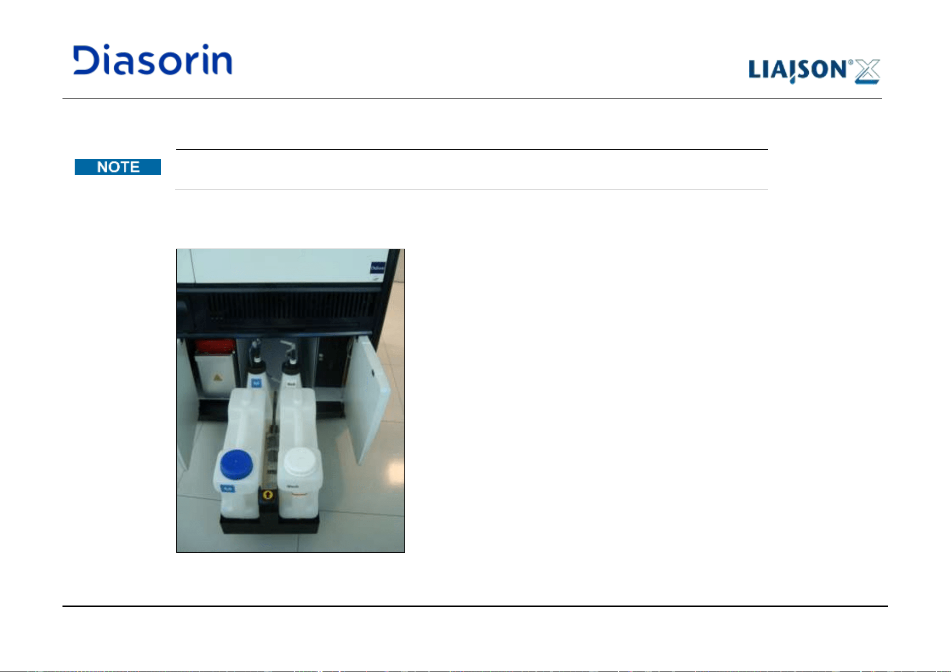
5 Use of the System
LIAISON XL - Instructions for use Page 5-25
Rev. L
5.5.4 Load and Unload the Water Tank
In case LIAISON
®
diluteX is connected to the analyzer, please do not follow this procedure, but refer directly to
LIAISON
®
diluteX User Manual.
1. Open the cabinet doors.
2. Pull the right drawer out of the cabinet (Figure 5-11).
Figure 5-11: Right drawer pulled out
Unload Procedure
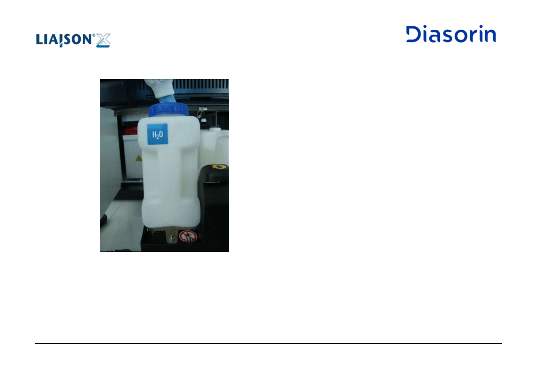
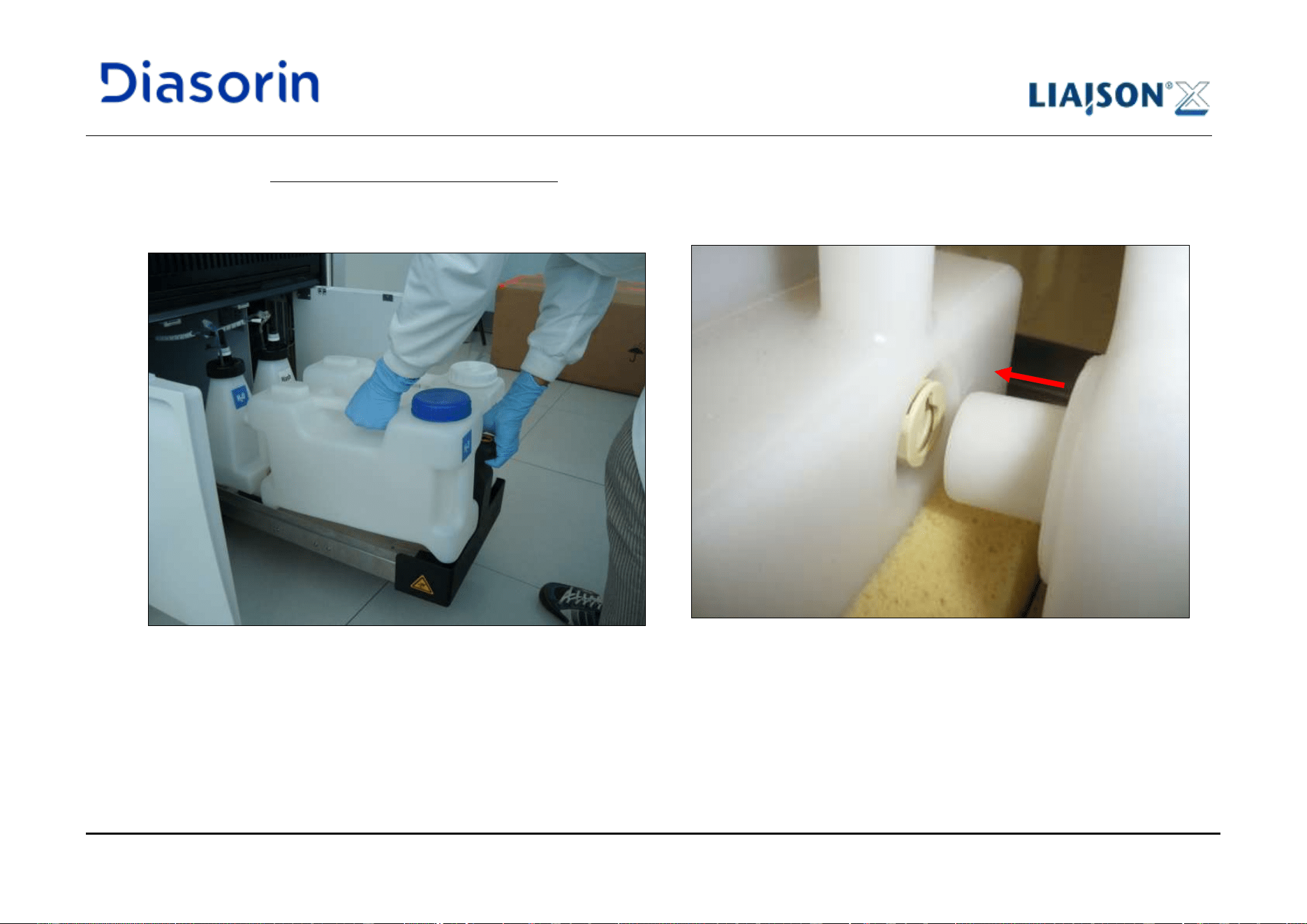
5 Use of the System
LIAISON XL - Instructions for use Page 5-27
Rev. L
1. Holding the handle of the drawer by hand (Figure 5-13 a), place the full water tank into the the right cabinet drawer of LIAISON
®
XL
system.
Note the audible click.
The centering pin must fit the intermediate tank (Figure 5-13 b).
a) b)
Figure 5-13: Water tank insertion and fitting
Load Procedure
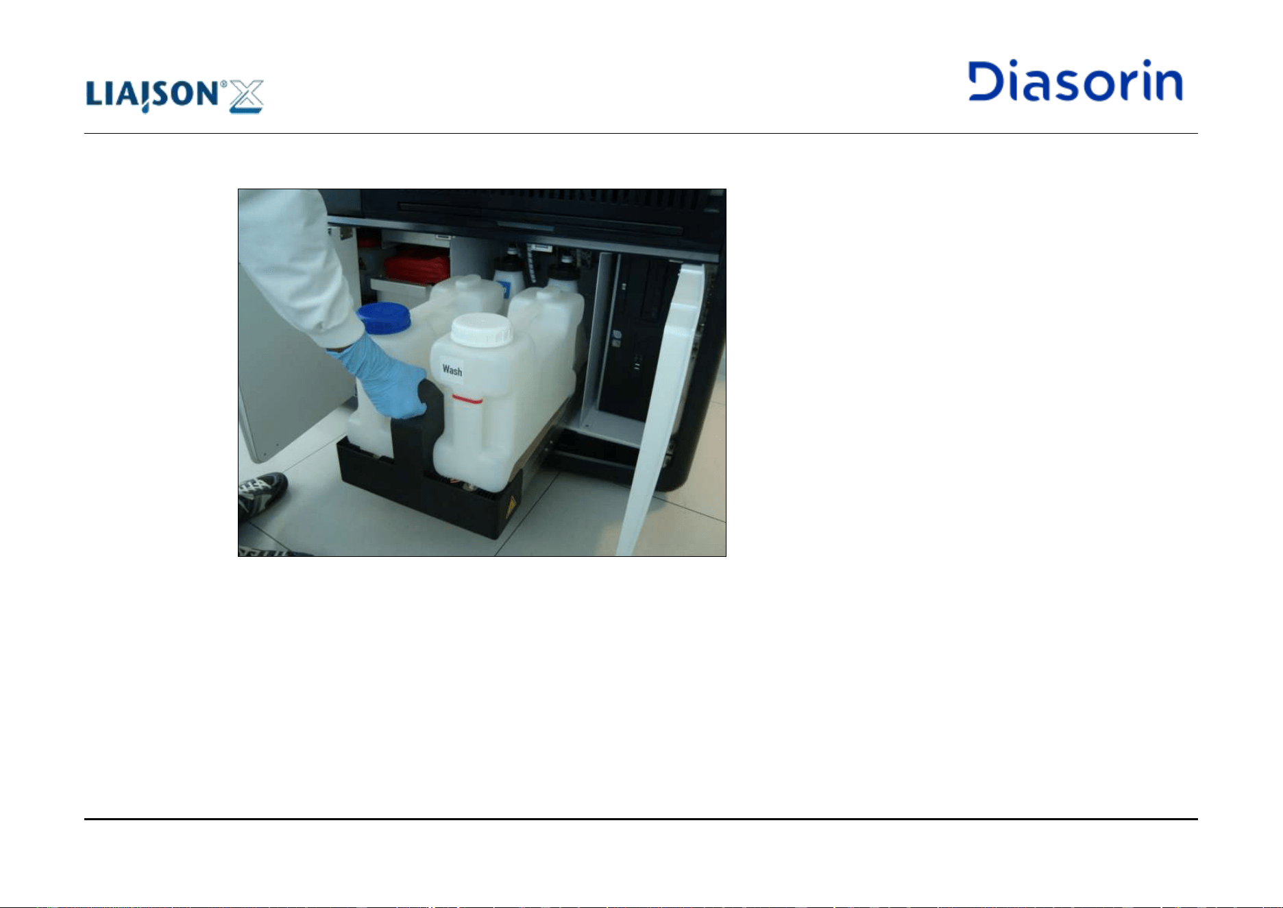
5 Use of the System
LIAISON XL - Instructions for use Page 5-29
Rev. L
5.5.5 Load and Unload the Wash Buffer Tank
5.5.5.1 Preparation
1. See instruction for use.
Before the wash buffer is handled or loaded into the LIAISON
®
XL system, the package information is to be read
thoroughly and followed by the user. Use the red line available on the tank as an aid during the preparation of the
wash solution (refer to chapter 1.10.9).
In case LIAISON
®
diluteX is connected to the analyzer, please do not follow this instruction but refer directly to
LIAISON
®
diluteX User Manual.
LIAISON
®
XL wash buffer must fulfill the requested ambient operating conditions during installation and should never
be used after defined expiration date for onboard stability.
Please do not take into account this caution if LIAISON
®
diluteX is connected to the analyzer.
After completion of the wash buffer preparation, the cap must be placed lightly on the container to allow proper
degassing of the wash buffer solution!
Please do not take into account this caution if LIAISON
®
diluteX is connected to the analyzer.
Freshly prepared or non-degassed wash buffer should not be used in the LIAISON
®
XL system.
Please do not take into account this caution if LIAISON
®
diluteX is connected to the analyzer.
The LIAISON
®
XL wash buffer container should be kept away from direct sunlight.
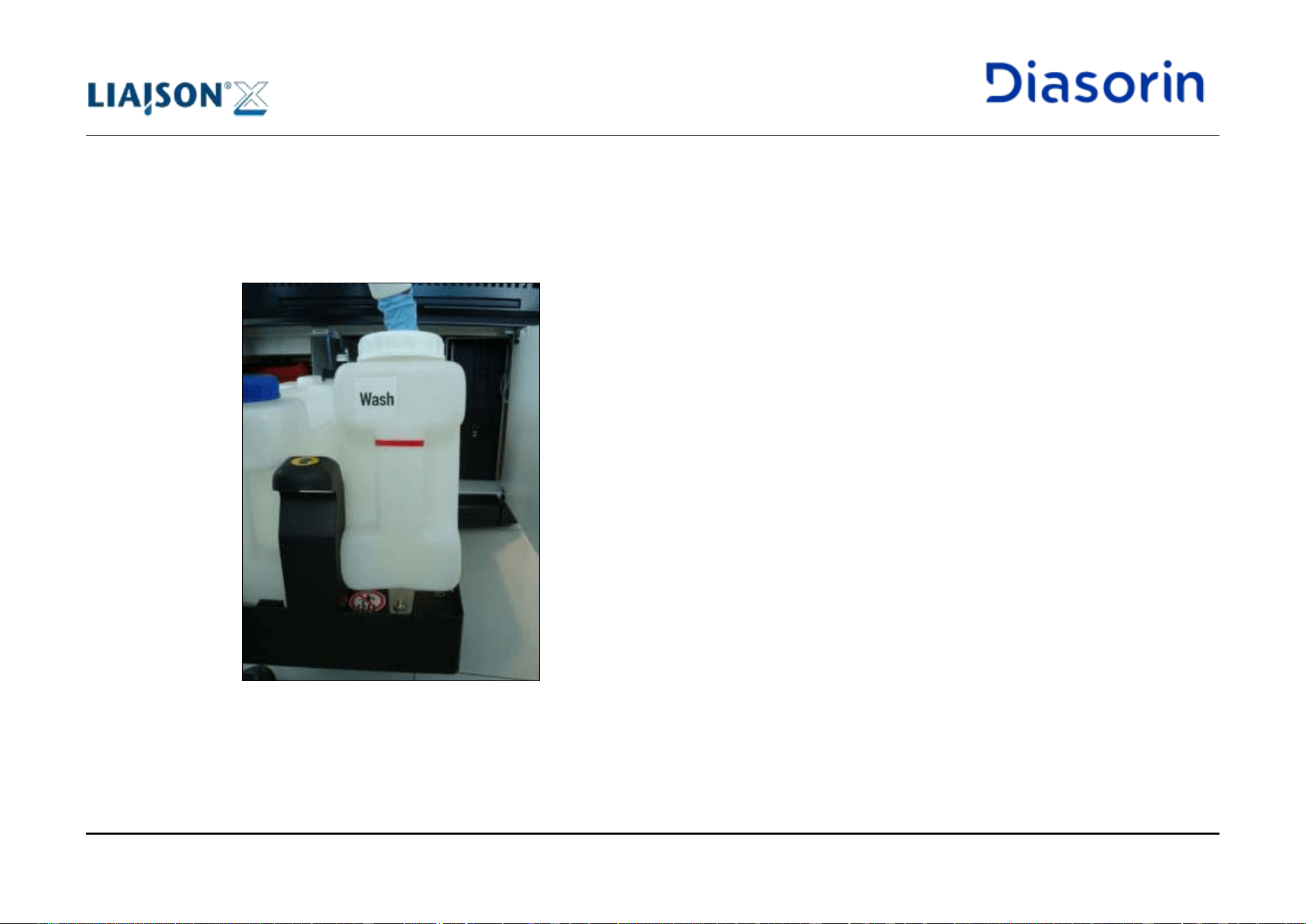
5 Use of the System
Page 5-30 LIAISON XL - Instructions for use
Rev. L
5.5.5.2 Procedure
1. Open the cabinet doors.
2. Pull the right drawer out of the cabinet (Figure 5-11).
3. Raise the front of the (empty) wash buffer tank approximately 2cm (0.8inch) (Figure 5-15).
Figure 5-15: Raise wash buffer tank
4. Pull the wash buffer tank out of the LIAISON
®
XL system.
Unload
Procedure
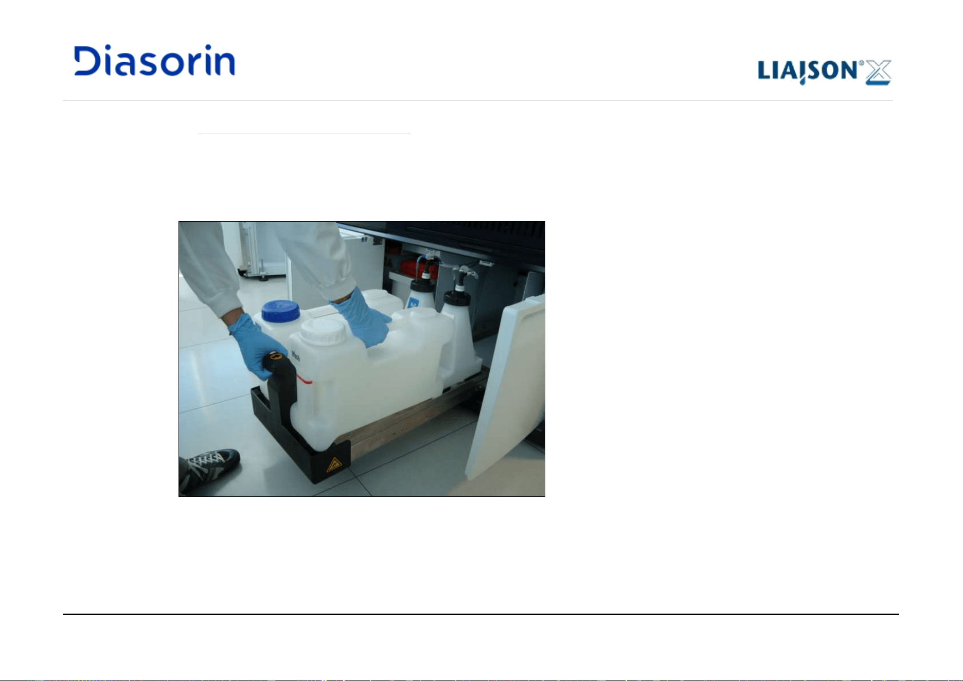
5 Use of the System
LIAISON XL - Instructions for use Page 5-31
Rev. L
1. Holding the handle of the drawer by hand (Figure 5-16), place the full wash buffer tank into the the right cabinet drawer of LIAISON
®
XL
system.
Note the audible click.
The centering pin must fit into the intermediate tank (Figure 5-13b).
2. Push the right drawer back into the cabinet (Figure 5-14).
3. Close the cabinet doors.
Figure 5-16: Wash buffer tank insertion
Load Procedure
5 Use of the System
Page 5-32 LIAISON XL - Instructions for use
Rev. L
5.5.6 Load and Unload the Liquid Waste Containers
See Biological safety in chapter 1.8.6.
Note the control light on the connector and remove only unused liquid waste containers (the control light is off). It is
possible to change the liquid waste container currently in use through the dedicated button, see chapter 6.10.1.
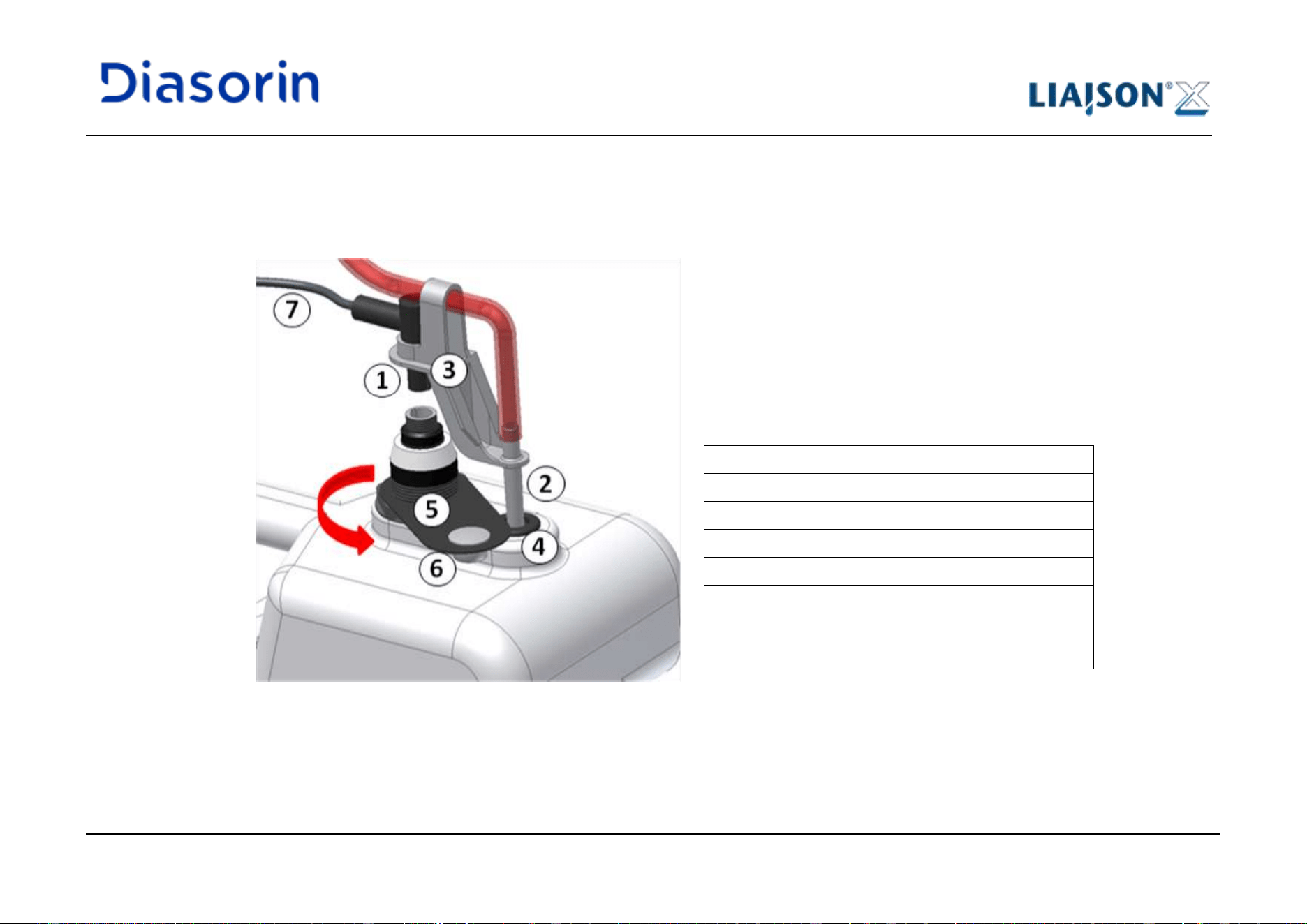
5 Use of the System
LIAISON XL - Instructions for use Page 5-33
Rev. L
5.5.6.1 Joint connector for waste
The joint connector (Figure 5-17) is used to manage the insertion/ removal of the waste sensor and tubing as a single task. A membrane
element avoids splashing of liquid when the liquid connector is removed.
Figure 5-17: Liquid waste container with sensor/ liquid joint connector
Item
Description
1
Sensor connector
2
Liquid tubing connector
3
Plastic joint
4
Membrane
5
Rubber strip
6
Cap
7
Sensor cable
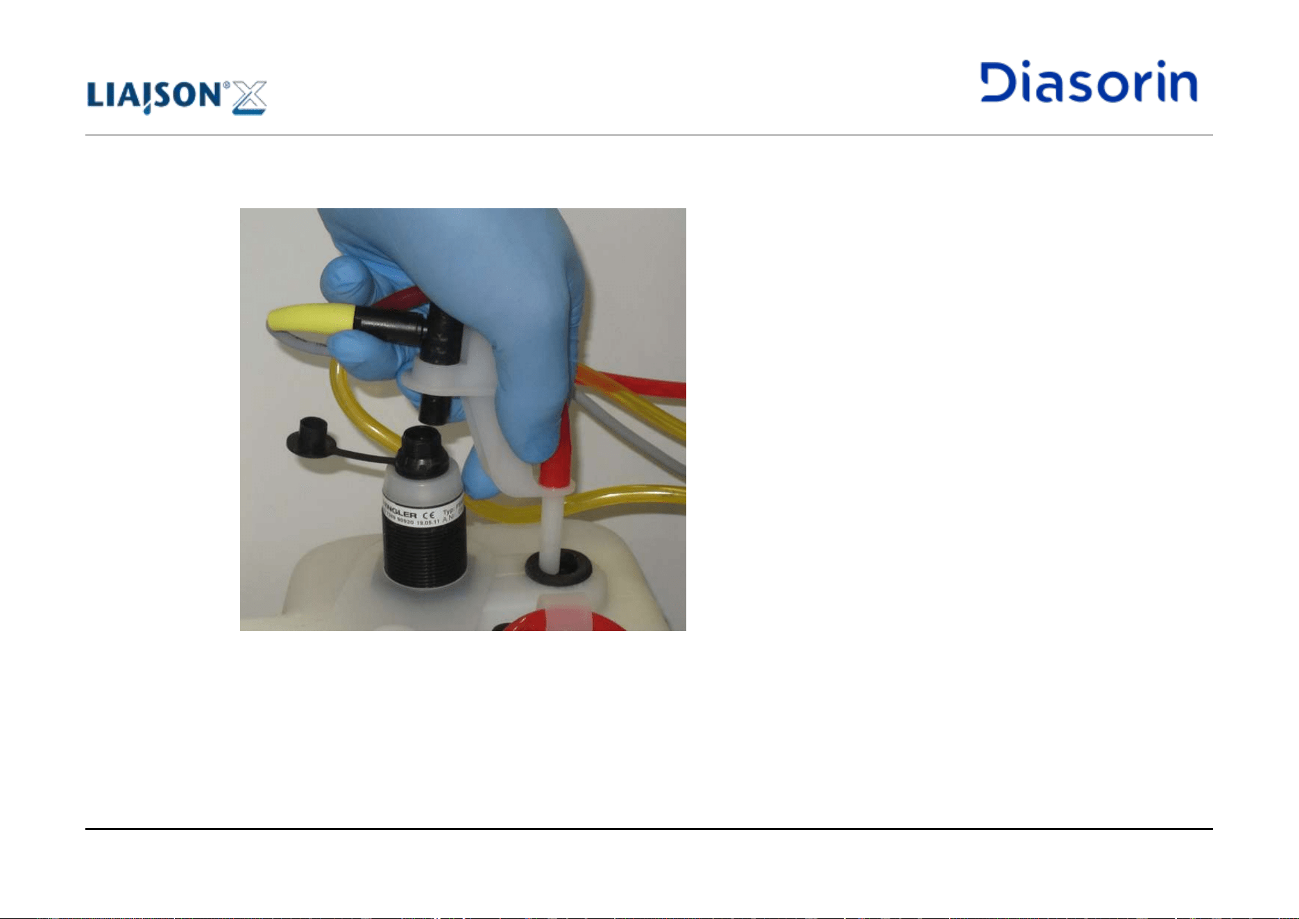
5 Use of the System
Page 5-34 LIAISON XL - Instructions for use
Rev. L
During the unload phase (Figure 5-18) the removal of the sensor connector also implies a removal of the liquid tubing from the dedicated
membrane; as a safety requirement, the sensor is completely disconnected before the liquid tubing is pulled completely out of the membrane.
Figure 5-18: When disconnecting the sensor, the tubing is also pulled out of the membrane
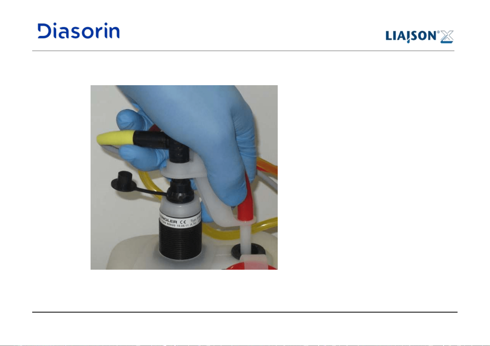
5 Use of the System
LIAISON XL - Instructions for use Page 5-35
Rev. L
During the load phase (Figure 5-19) the insertion of the liquid tubing into the membrane also implies the connection of the sensor; as a safety
requirement, the tubing is pushed into the membrane before the sensor is completely connected (i.e. an audible click is heard when
connection is performed).
Figure 5-19: When pushing the tubing into the membrane, the sensor is also connected
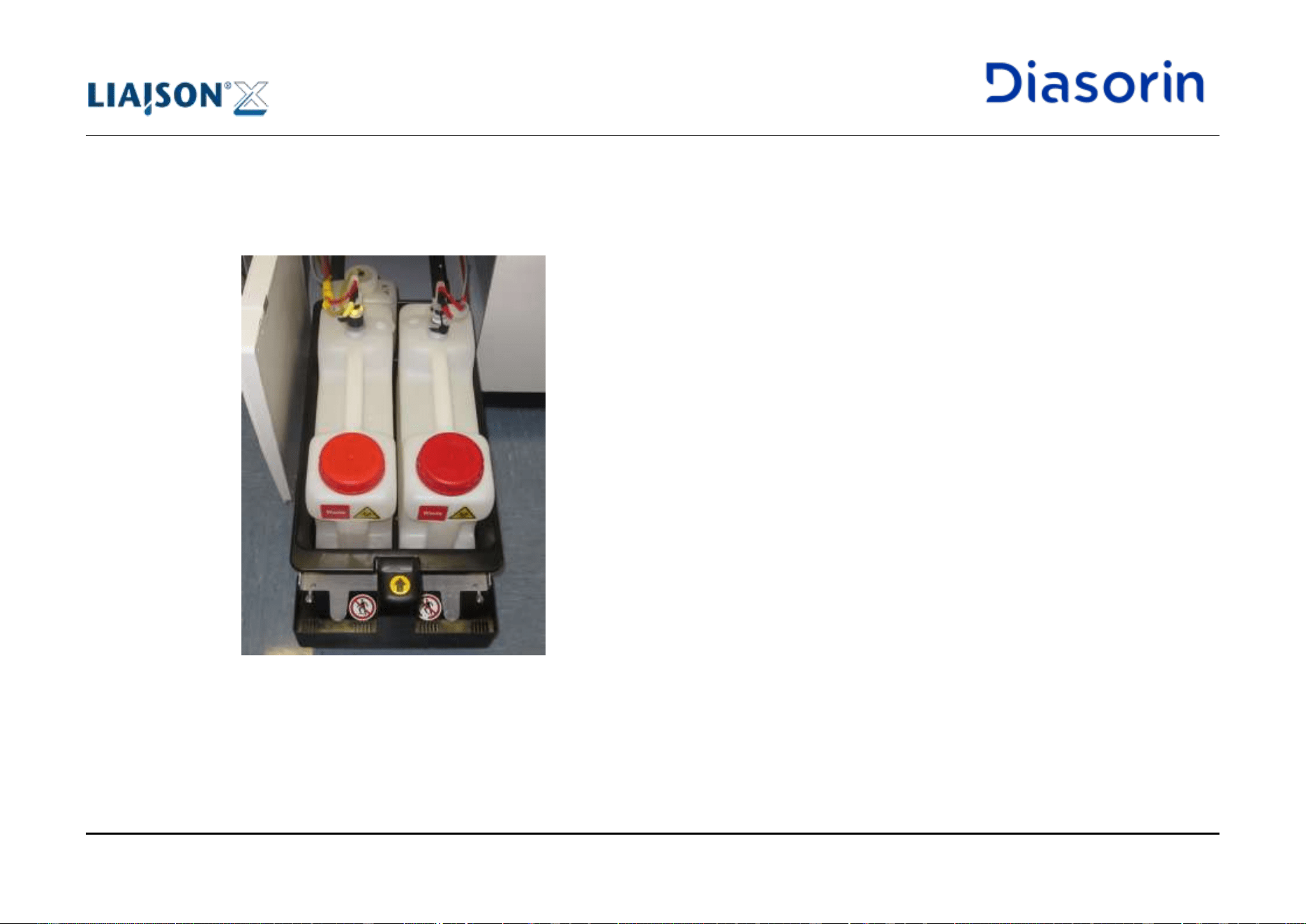
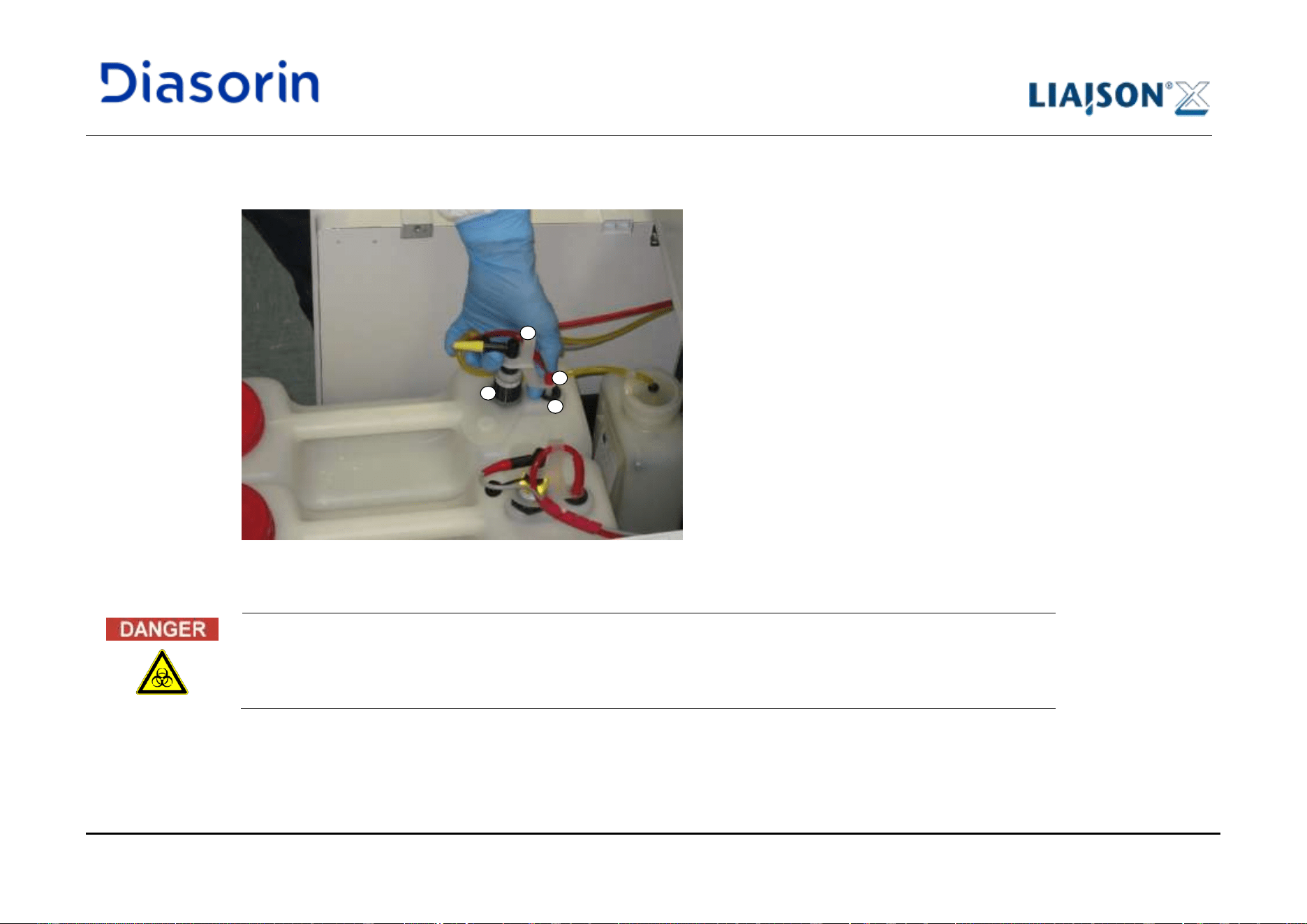
5 Use of the System
LIAISON XL - Instructions for use Page 5-37
Rev. L
3. Unplug the sensor connector (1). Due to the presence of the plastic joint (3), the liquid tubing connector (2) will be also removed from the
membrane (4).
Figure 5-21: Removal of sensor and liquid tubing connectors
As a safety requirement, the sensor is completely disconnected before the liquid tubing connector is pulled
completely out of the membrane.
1
3
2
4
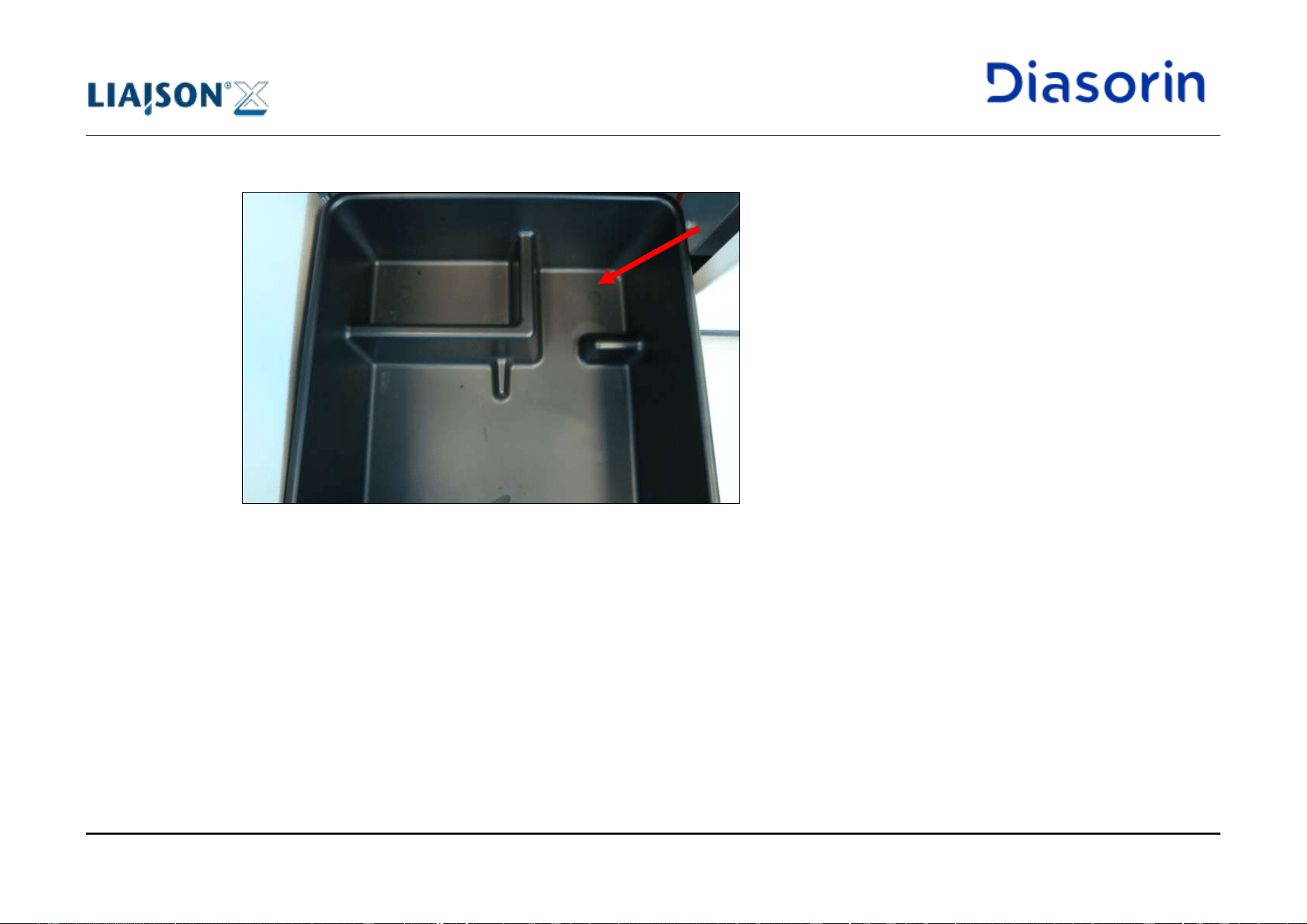
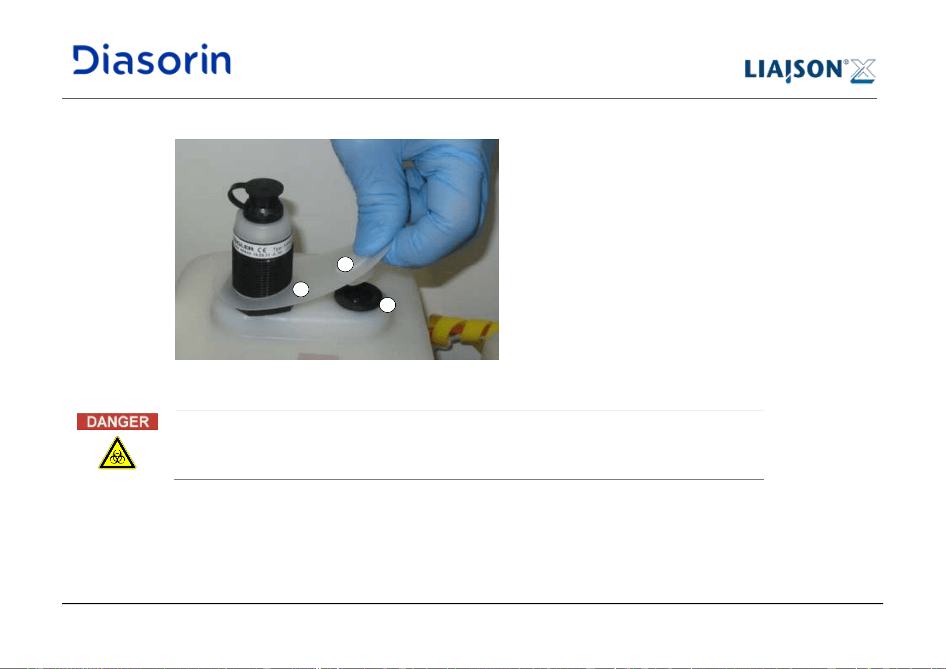
5 Use of the System
LIAISON XL - Instructions for use Page 5-39
Rev. L
5. Before pulling the container out of the basin, turn the rubber strip (5) and cover the membrane (4) by using the available cap (6).
Figure 5-23: Rotation of the rubber strip and closure of the membrane with the cap
In order to prevent splashes of liquid from the membrane, always close the cap before handling the container.
5
4
6
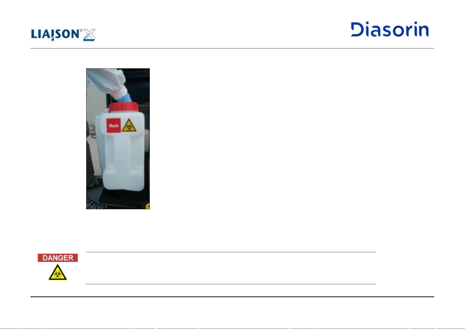
5 Use of the System
Page 5-40 LIAISON XL - Instructions for use
Rev. L
6. Completely remove the waste container (Figure 5-24) from the basin.
Figure 5-24: Waste container removal
7. Once the available waste disposal area is reached in the laboratory, empty the waste container and preferably add 200 mL of commercial
hypochlorite or bleach. In case commercial sodium hypochlorite solutions are used (e.g. bleach), avoid formulations featuring any
fragrance, surfactant, other oxidizer or additive.
During the liquid waste disposal, do not remove the cap from the membrane.
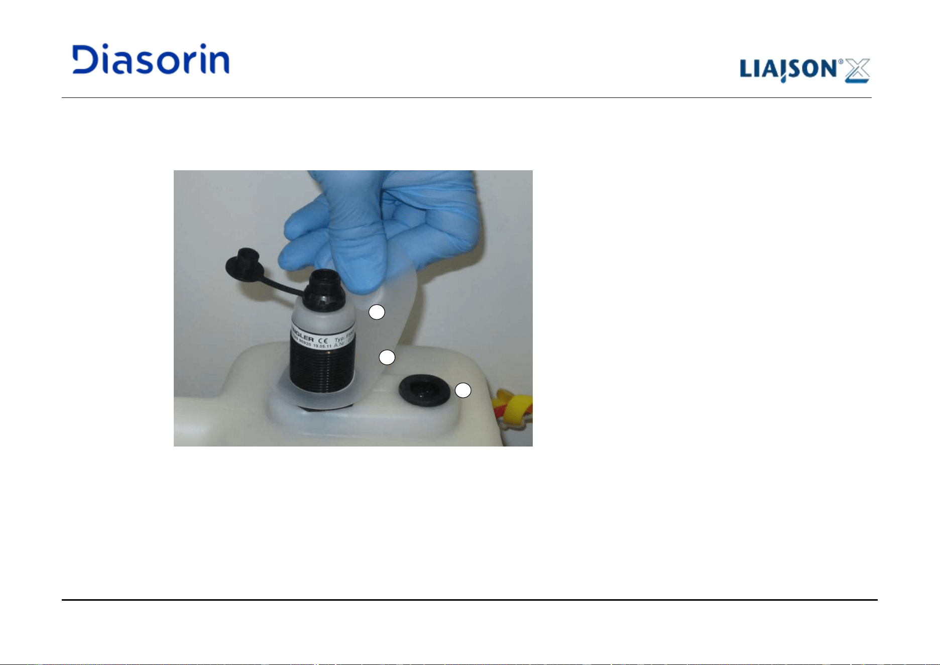
5 Use of the System
LIAISON XL - Instructions for use Page 5-41
Rev. L
8. Put the waste container back into the waste basin of the left drawer.
9. Remove the cap (6) from the membrane (4) by turning the rubber strip (5). Cap shall be removed only just before connecting the sensor
and the liquid tubing.
Figure 5-25: Rotation of the rubber strip and opening of the membrane
10. Verify the sensor cable (7) is oriented to the front, as represented in Figure 5-26. Also verify that the male & female grooves are aligned,
see Figure 5-27.
Load Procedure
6
4
5
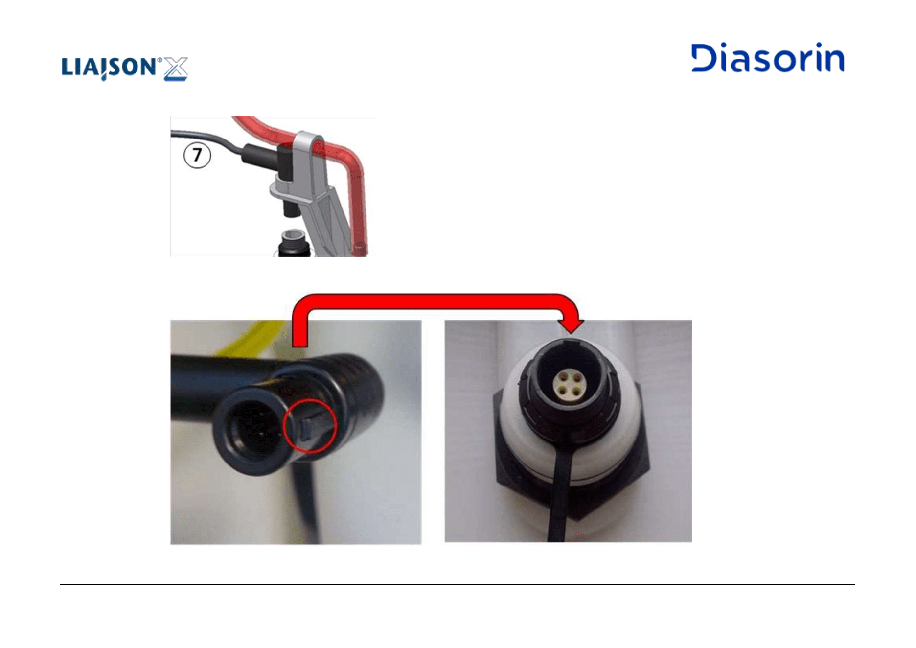
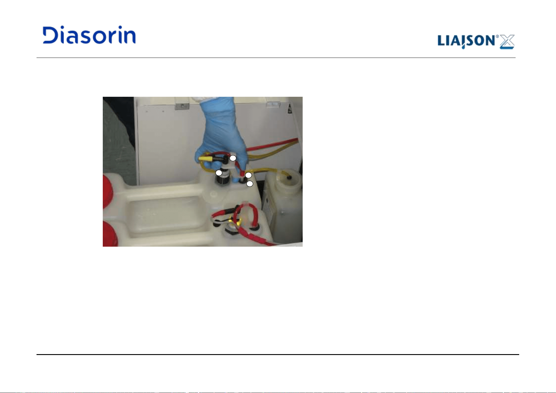
5 Use of the System
LIAISON XL - Instructions for use Page 5-43
Rev. L
11. Push the liquid tubing connector (2) into the membrane (4). Due to the presence of the plastic joint (3), the insertion of the liquid tubing
connector (2) into the membrane (4) implies also the connection of the sensor (1). An audible click is heard when the sensor connection
is completed.
Figure 5-28: Insertion of sensor and liquid tubing connectors
2
4
3
1
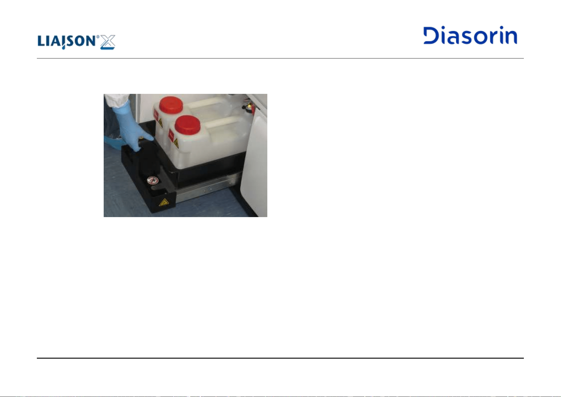
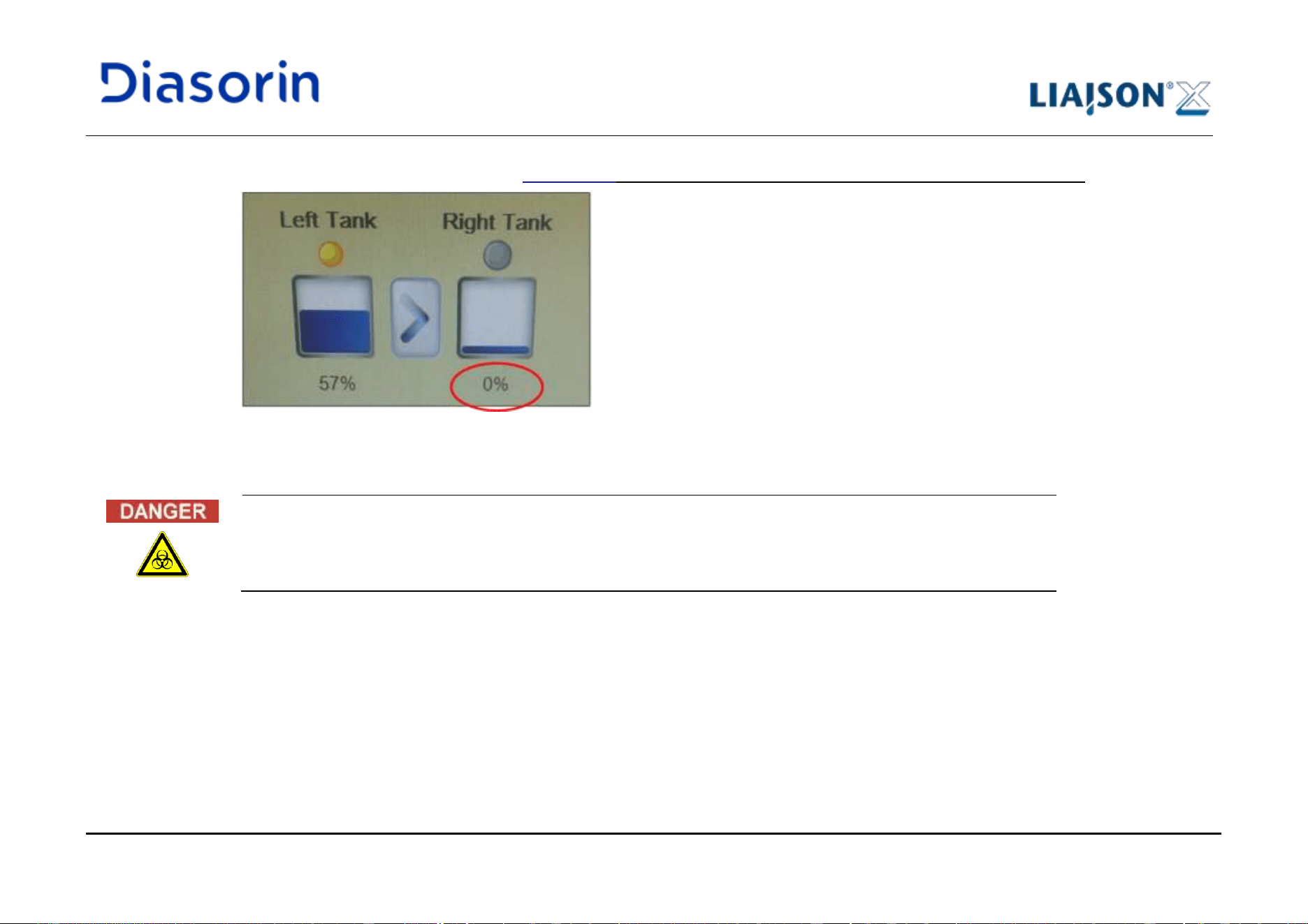
5 Use of the System
LIAISON XL - Instructions for use Page 5-45
Rev. L
14. Check the Status/ Summary menu. LIAISON
®
XL SW must show 0% for an empty container correctly connected.
Figure 5-30: Percentage indicated in case of empty container
Other values may indicate bad/ wrong connection status, therefore leading to malfunctions with consequent risk of
spillage of waste liquid.
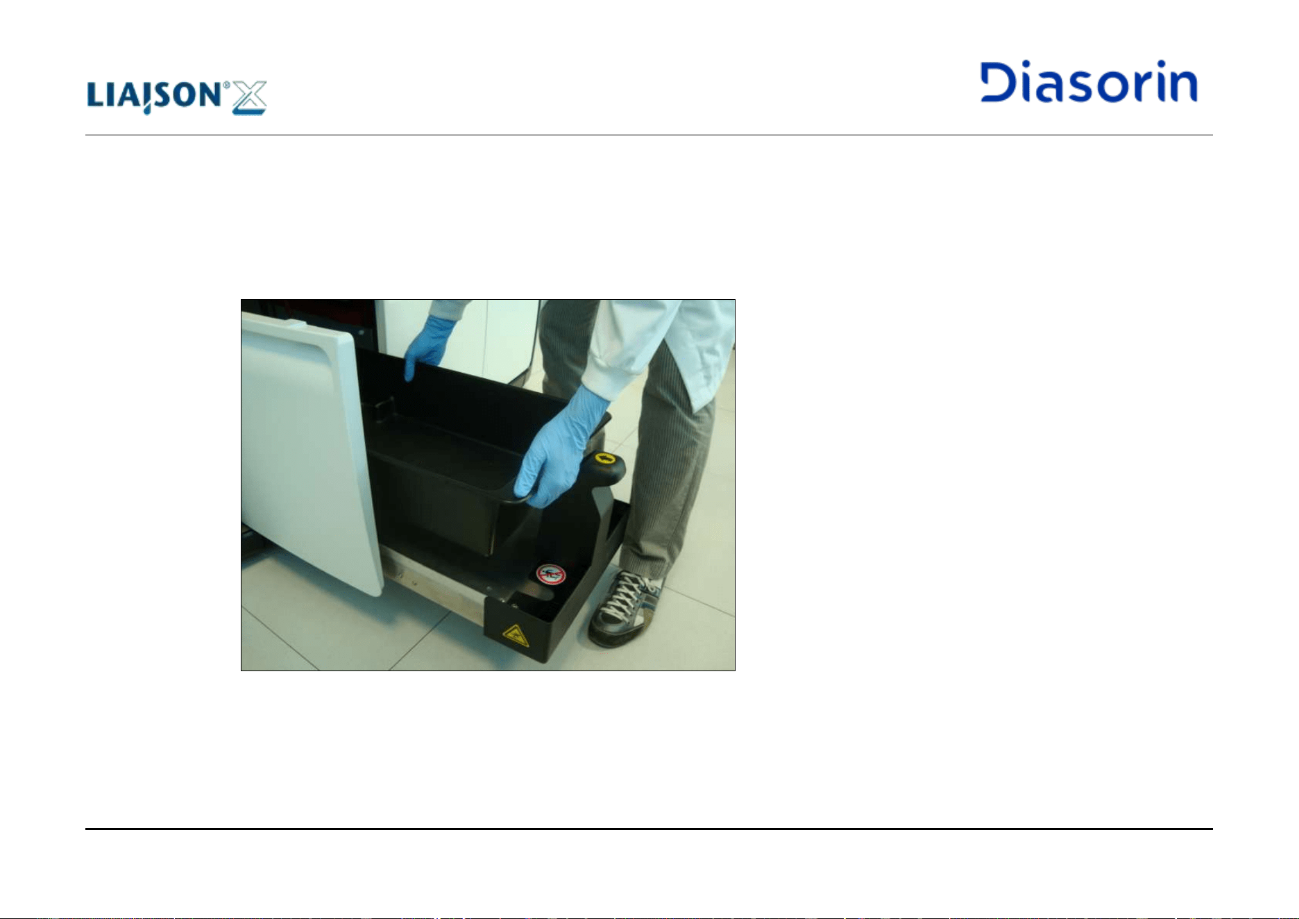
5 Use of the System
Page 5-46 LIAISON XL - Instructions for use
Rev. L
5.5.6.3 Waste basin handling
If spillage from waste tanks occurs, liquid will be collected in the waste basin, thus preventing the cabinet area from contamination.
In case of the presence of liquid inside the waste basin, raise it up from the drawer (Figure 5-31), empty it and perform its decontamination
according to what indicated in chapter 1.8.6 and 1.8.8.
The same procedure shall be applied to handle the basin equipped on instruments without cabinet drawers.
Figure 5-31: Waste basin removal
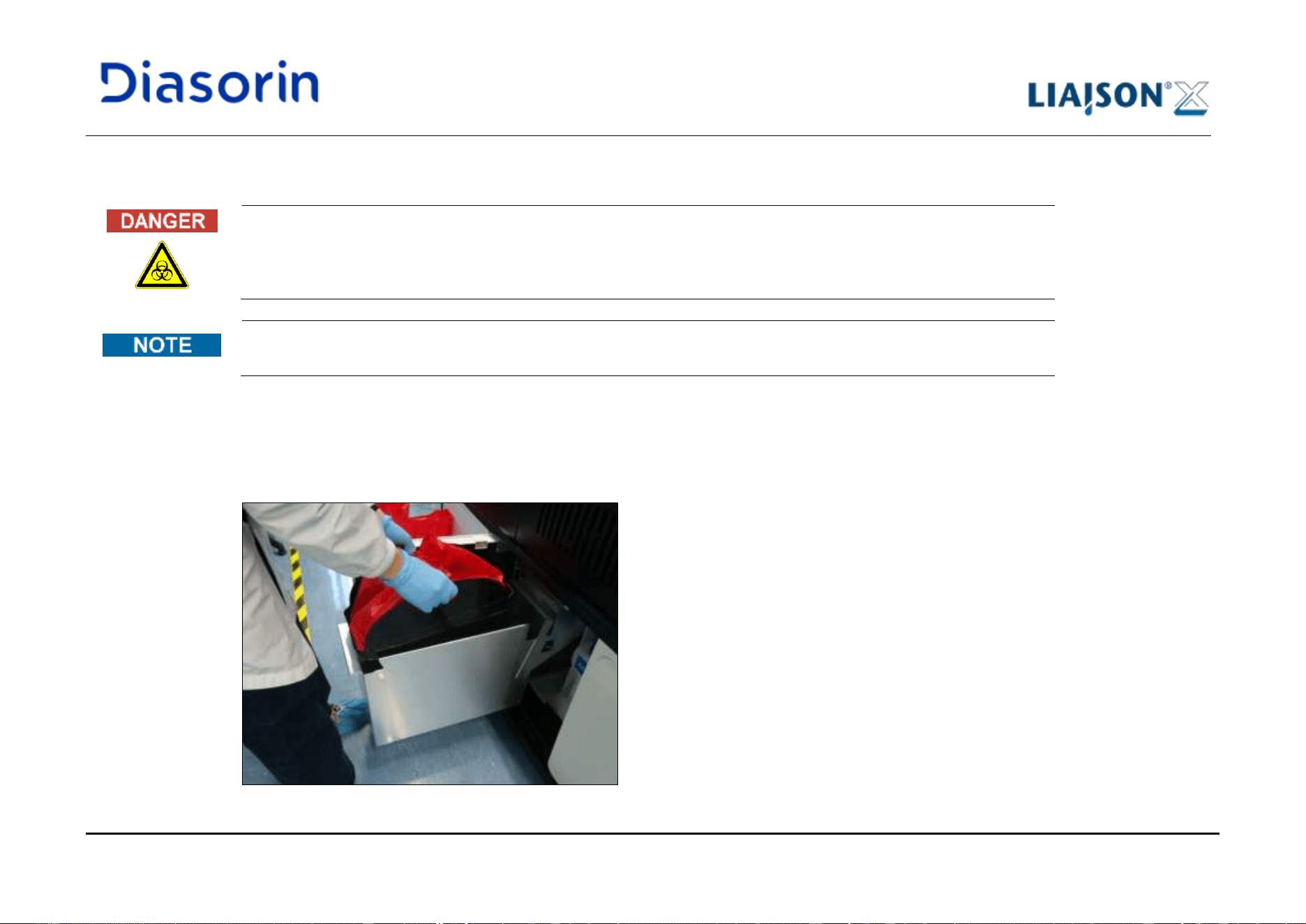
5 Use of the System
LIAISON XL - Instructions for use Page 5-47
Rev. L
5.5.7 Load and Unload the Solid Waste Bag
See Biological safety in chapter 1.8.6.
The LIAISON
®
XL system does not monitor the presence of the Solid Waste Bag, therefore the user shall ensure that
it is loaded before starting a run.
1. Open the cabinet and pull the solid waste drawer out of the LIAISON
®
XL system.
2. Unhook the solid waste bag from the tensioner in the back of the drawer.
3. Unhook the solid waste bag from the front of the drawer.
4. Remove the solid waste bin (with the bag inside) from the drawer of the instrument (Figure 5-32).
Figure 5-32: Waste bin and bag removal
Unload
Procedure
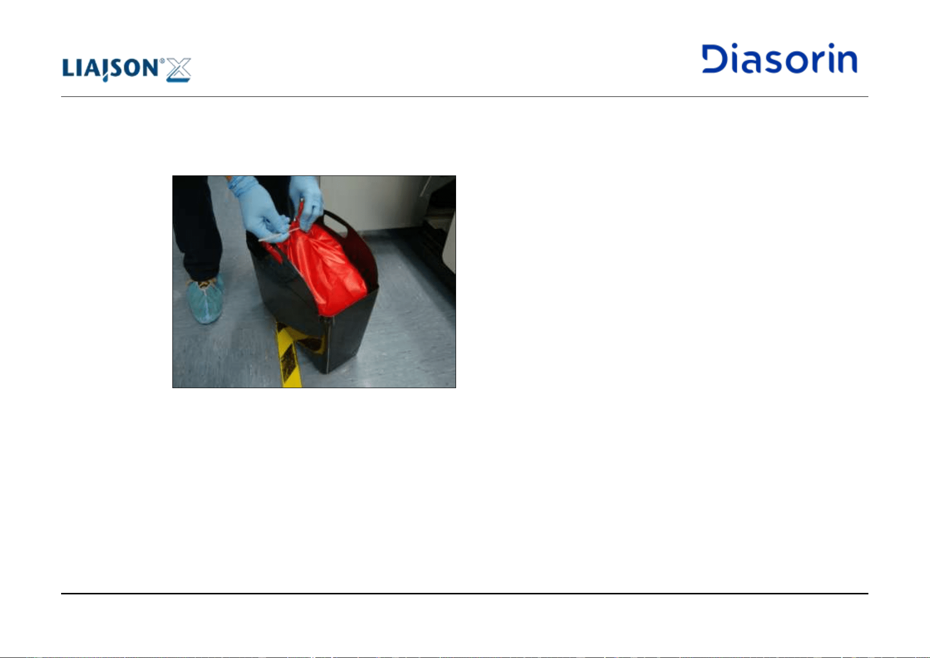
5 Use of the System
Page 5-48 LIAISON XL - Instructions for use
Rev. L
5. Close the solid waste bag with the dedicated strap (Figure 5-33).
6. Without removing it from the bin, bring the waste bag to the disposal point (Figure 5-34).
7. Once near the disposal point, dispose the bag once pulled it out of the bin.
Figure 5-33: Bag closed with the strap
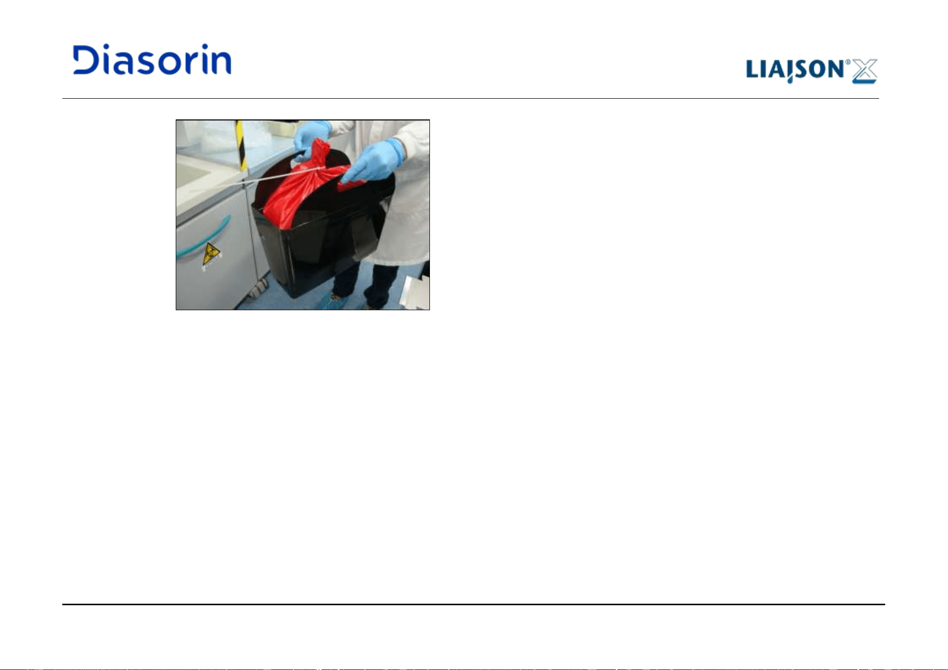
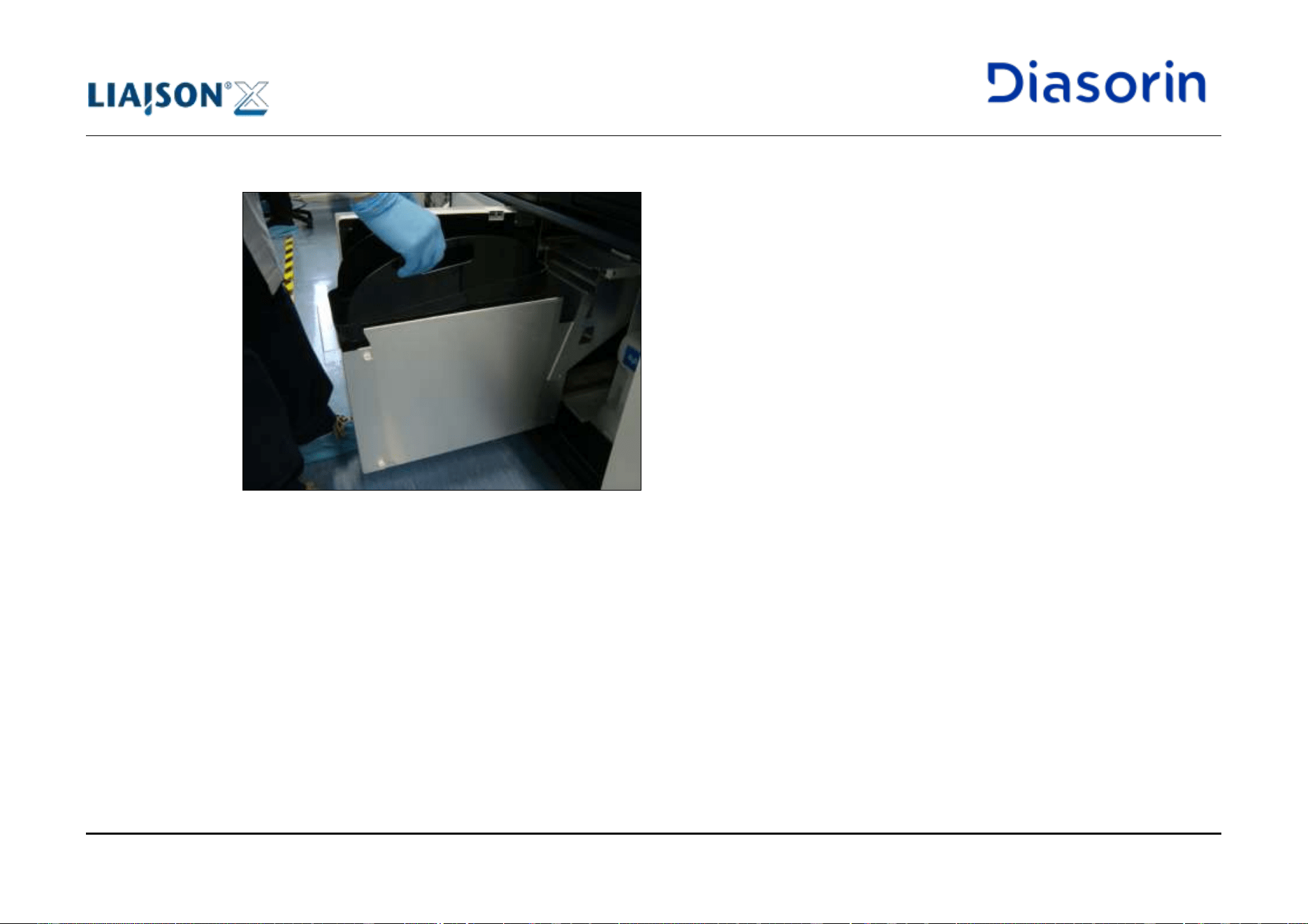
5 Use of the System
Page 5-50 LIAISON XL - Instructions for use
Rev. L
1. Insert the solid waste bin into the solid waste drawer (Figure 5-35).
Figure 5-35: Waste bin insertion
2. Place a new solid waste bag into the solid waste bin.
3. Hook the solid waste bag to the tensioner available in the back of the solid waste drawer.
4. Hook the solid waste bag to the front of the drawer.
5. Adjust the positioning of the bag inside the drawer, in order to guarantee the availability of the whole volume.
6. Slide the solid waste drawer into the LIAISON
®
XL system.
7. Close the cabinet.
8. Select the sub-category Summary of the category Status (refer to chapter 6.10.1) and press Reset button.
Load Procedure
5 Use of the System
LIAISON XL - Instructions for use Page 5-51
Rev. L
5.6 Load Patient Samples or Controls and Assign Assays
In this section, it is described how patient samples or controls are loaded into the system and how they can be assigned to one or several
assays.
5.6.1 Load Patient Samples
See Biological safety in chapter 1.8.6.
Traceability of the Diagnostic Results
For maintaining traceability of the diagnostic results, the patient sample should be handled according to the
laboratories quality system as described in the local requirements.
Maintaining Safety
For maintaining safety, the samples must fulfil the requested installation and operating conditions as stated in the
assay instruction for use.
Sample
Preparation
5 Use of the System
Page 5-52 LIAISON XL - Instructions for use
Rev. L
Sample Area Flap closure
The sample area flap must be left open only for the time necessary to load sample racks. Leaving the sample area
flap open for more than 5’, the sample barcode reader will be disabled; in this case, it would be necessary to close
the sample area flap and open it to make it work again.
Due to certain mechanical restrictions and safety precautions, the sample to be used on the LIAISON
®
XL system must have the following
characteristics:
• Human serum, urine or plasma may be used (sample matrix depends upon assay intended use).
• The anticoagulants citrate, EDTA and heparin may be used (allowed anticouagulants depend upon assay intended use).
• Blood should be collected aseptically by venipuncture, allowed to clot, and the serum separated from the clot as soon as possible.
• Samples having particulate matter, turbidity, lipaemia, or erythrocyte debris may require clarification by filtration or by centrifugation before
testing.
• Grossly haemolyzed or lipaemic samples as well as samples containing particulate matter or exhibiting obvious microbial contamination
should not be tested.
• Check for and remove air bubbles before testing.
• Check that the sample volume is sufficient to run the required amount of tests (as described in the "Instructions For Use" on the kits being
used).
• In case of plasma gel separator containers, the amount of sample should be at least 500 µL plus the volume required to run the test.
Air Bubble Formation or Clotting
Air bubble formation or clotting of the samples must be avoided as these may alter the liquid detection functionality
and hence cause unreliable results. To avoid clots, the samples should be treated accordingly (e.g. centrifuged) prior
to the use in the LIAISON
®
XL system.
After all criteria have been observed concerning the sample quality, the samples must be inserted into tubes and then into sample racks.
The following procedure explains in detail the proper steps for doing so.
5 Use of the System
LIAISON XL - Instructions for use Page 5-53
Rev. L
• Only load and unload racks if explicitly requested to do so.
• Only load and unload racks on the specified lanes.
• Check the correct transfer/input of all reagent and sample names.
• Remove all caps from the sample tubes.
Error at Loading/Unloading of Racks, Reagents and Samples
Improperly loaded or unloaded racks, reagents or samples can cause wrong results due to incorrect pipetting
activities.
Only tubes of the same type may be used for each rack, to avoid problems during the aspiration of liquids. The tube
type must be approved for the relevant rack.
Do not rotate bar-coded sample tubes after placement in sample racks. Rotating tubes when placed in sample racks
may cause damage to the bar-code and render the label unfit for future usage.
Use only exact modelling of tubes and bottles to ensure correct tracking.
1. Place the sample tubes in the sample racks.
• Sample tube diameter:
Use only sample tubes according to the used rack type (see chapter 4.2.5.3).
• Bar coded patient samples:
Make sure that the bar-code labels on the individual patient samples face left so that they can be scanned by the bar-code reader when
the rack is inserted.
Procedure
5 Use of the System
Page 5-54 LIAISON XL - Instructions for use
Rev. L
• Non bar coded patient samples or unreadable bar-code labels:
When using non bar coded sample tubes or tubes with unreadable bar codes, the sample ID's (SID's) must be entered manually (see
below). Note that the SID manual entry practice is considered not state-of-art as a potential source of sample mismatch, out of the system
control, leading to wrong diagnostic results.
2. Open the sample loading bay flap.
The software will show automatically the Samples sub category tab of the Loading main category tab.
See Laser safety in chapter 1.8.4.1.
Always use the rack handle when pushing in the racks into the rack system or pulling them out again.
3. Insert the first sample rack (carefully to avoid tipping over and spilling of bottles or tubes) into the sample loading bay on the lane marked
by the flashing LED. Place the rack in front of the lane and then push evenly up to the limit stop (with the tappet in the contact opening on
the rear panel).
The rack bar codes and the individual sample tube bar codes are read. If the rack has been inserted properly all the way, the LED goes off
for this position, and starts flashing at the next position that can be loaded.
4. If there is a problem with the rack identifier, an input box appears:
• Look at the rack label letter (rack identifier) on the front of the rack.
• Enter the rack identifier manually.
• Click on the OK button.
Never load more than one rack at a time! For proper bar-code identification the racks must be loaded one after
another, as indicated by the LEDs.
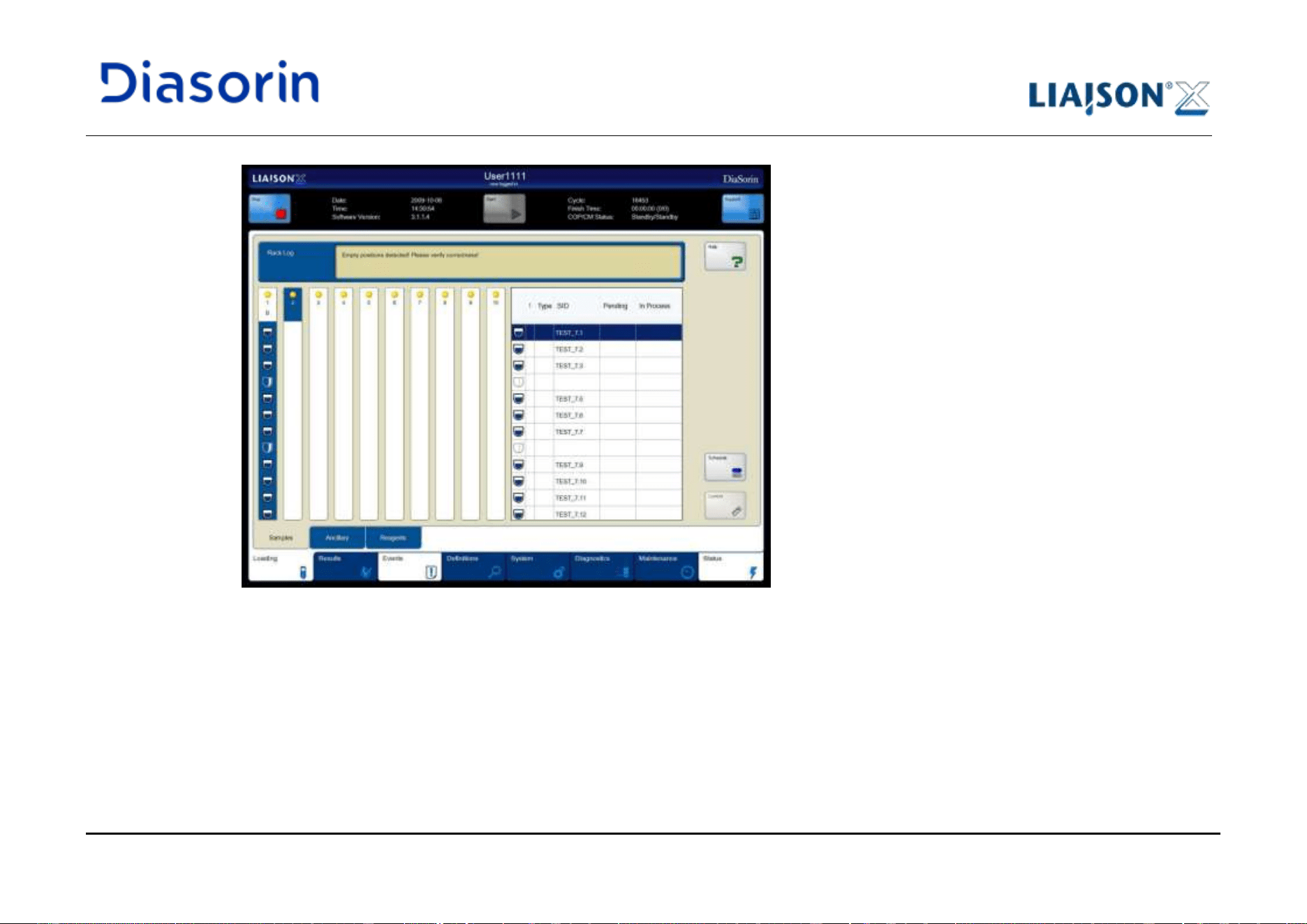
5 Use of the System
Page 5-56 LIAISON XL - Instructions for use
Rev. L
Function
Description
1 ... 10
Lanes of the loading bay for sample racks.
The display is divided into two parts:
• Upper part:
Click on the upper part (lane number and indicator) of an empty lane to load a sample rack on
this lane.
The upper part reflects also the rack status via LEDs below the lane (see chapter 4.2.5).
• Lower part:
Click on the lower part (sample rack) to select a rack. All samples will be shown in the table on
the right side.
Control
Opens the control picklist and allows the selection of a control or the creation of a new control
definition. The bar-code of that control is assigned to the current (empty) SID field.
The Control button is disabled if the SID field is not empty.
Rack log
The Rack Log field shows information about a loaded or selected sample rack.
• Loading errors
• Positions without bar-code or unreadable bar-code
• SID problems (e.g. duplications)
Schedule
Shows the Worklist tab to create or edit worklists for samples and controls (see chapter 6.3.1.1).
Standard buttons
For standard buttons (e.g. arrow buttons, lock, Print) see chapter 6.1.
Table 5-7: Functions of the Samples sub category
5 Use of the System
LIAISON XL - Instructions for use Page 5-57
Rev. L
The samples table shows all positions of the selected rack.
Column
Description
!
Shows an exclamation mark for high-priority samples (STAT).
Type
Shows an empty cell for samples or a symbol for calibrators and controls:
Calibrators
Controls
Expired controls
5 Use of the System
Page 5-58 LIAISON XL - Instructions for use
Rev. L
SID
Shows the sample ID, calibrator ID and control ID. The SID is read via bar-code scanner or entered
by operator (if bar-code not present or unreadable).
Notes:
The SID must be unique.
Two or more samples with the same SID are not allowed to load at the same time.
Use only the following characters:
• A - Z (a - z are converted to upper case)
• 0 - 9
• minus (-), dot (.), dollar sign ($), plus (+), percent sign (%), number sign (#), ampersand (&),
equal (=), blank space ( ), semicolon (;) and slash (/).
• The SID of controls may not begin with #.
A SID may be 3 to 17 characters long and shall not contain heading or trailing spaces.
The SID of external calibrators begins with a predefined prefix character and contains the assay
abbreviation or article number.
Note:
The SID field is write protected, if any of the following applies:
• the rack is in "Error"
• the SID was read via bar-code (and accepted, i.e. not deleted because of duplication or illegal
character)
• the Control button was pressed for that SID at least once since the SID was recognized
(i.e. un-pressing that button does not allow typing, it's necessary to unload and reload the rack)
• either a workorder or a patient definition for that SID is present in the work-database
(visible in the sub category All of the main category Results, see chapter 6.4.1).
Symbol
See table below.
Pending
If assays are assigned to the sample: Shows all assays in status Placed or Failed for the sample.
In Process
If assays are assigned to the sample: Shows all started assays in status Scheduled, Active or
Measured for the sample.
Table 5-8: Columns of the loaded samples table
5 Use of the System
LIAISON XL - Instructions for use Page 5-59
Rev. L
Light-Check must be loaded as an ancillary reagent.
Any sample beginning with the special characters (i.e. “#” or “$”) will be displayed as control or calibrator, no matter if
they will be treated as controls or calibrators or patient samples.
The support of slash (/) as SID character requires the intervention of field service authorized representative.
Please contact your local DiaSorin representatives to enable it.
5. Note the Rack Log field for information about the loaded (or selected) sample rack. The Rack Log field shows:
• Loading errors
• Empty positions (positions without tubes, without bar-coded tubes or with tubes with unreadable bar-codes)
• SID problems (e.g. duplications)
6. Click on the rack shown and check the sample ID's in the SID column of the table.
Symbol
Description
Loaded sample tube with known SID.
Loaded sample tube without bar-code or unreadable bar-code,
or
no tube loaded. The SID is empty.
Sample in process.
Sample off-line
(If a sample is off-line, unload it, check its conditions and
reload again when ready for use.)
Table 5-9: Symbols
5 Use of the System
Page 5-60 LIAISON XL - Instructions for use
Rev. L
Sample IDs shall not contain heading or trailing spaces. The system will deny spaces if entered manually via the on
screen keyboard or read via bar code.
7. Check all shown SID's of the loaded sample tubes.
An incorrect SID will be replaced by an empty field (check also the Rack Log): If so:
• Click on the affected SID cell.
• Enter the correct SID.
• Repeat the steps for all incorrect SID's.
8. Load the other sample racks in the same manner.
9. Close the sample loading bay flap.
5.6.1.1 Loading Error
It is possible to obtain an error while loading a sample rack.
Typical problems may include (but are not limited to):
• Damaged bar codes on the sample rack.
• The sample rack is inserted too fast or too slow. Ask local service support for a tutorial about proper loading speed.
• The sample rack is inserted on the wrong lane.
• The bar-code scanner of the sample loading bay is damaged.
Errors with sample racks will appear immediately.
• The lane LED of the affected sample loading bay lane will be indentified by a flashing LED.
• The Samples display of the LIAISON
®
XL software shows an Error note on the loaded sample rack picture.
• The Rack Log on the Samples display shows an error message when that lane is selected..
5 Use of the System
LIAISON XL - Instructions for use Page 5-61
Rev. L
Troubleshooting:
• Remove the sample rack.
• Check and correct the bar-code labels.
• Insert the sample rack again.
• If the system cannot recognize the rack, check the bar-code scanner of the sample loading bay with another sample rack, and call service
if the error occurs again.
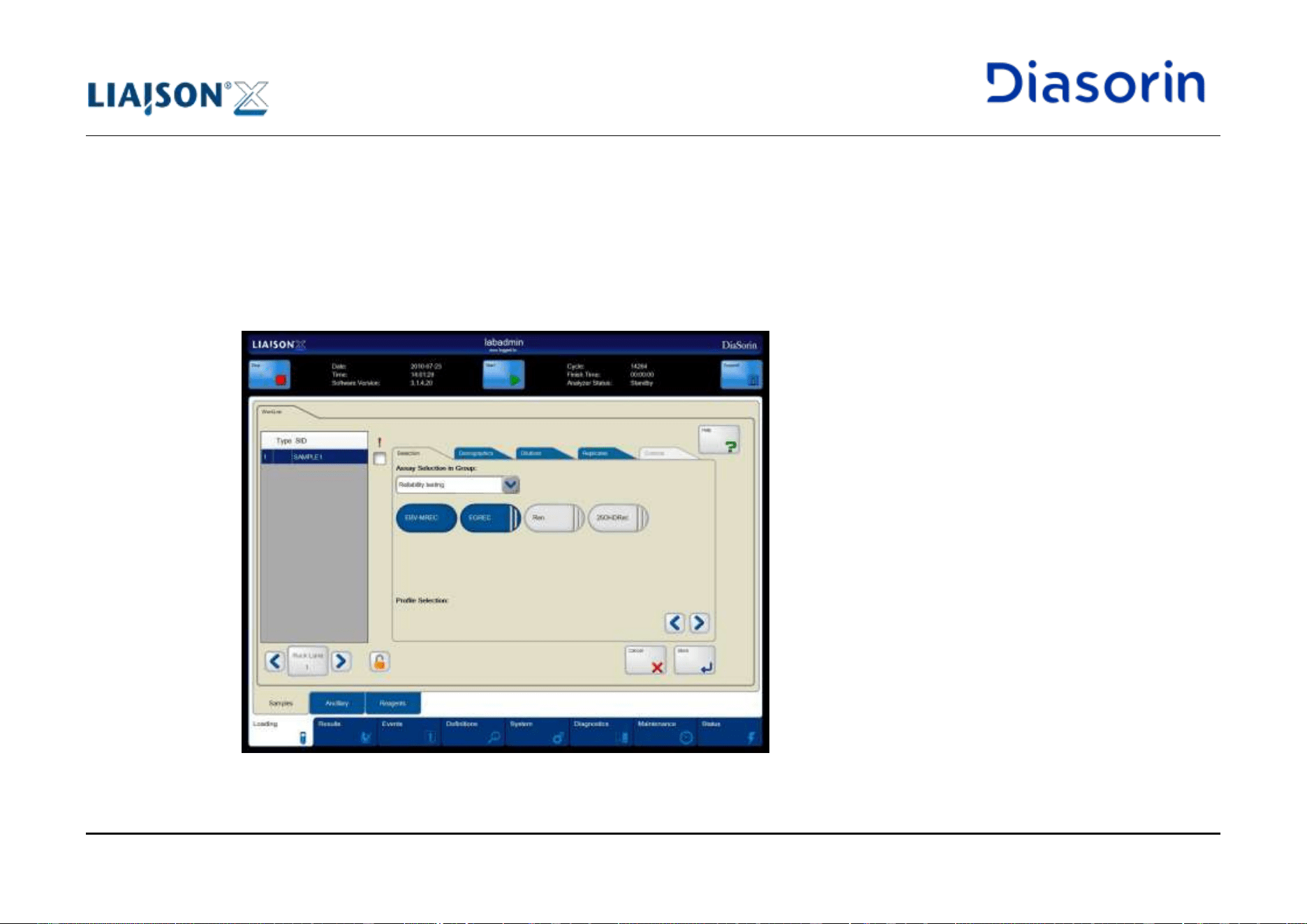
5 Use of the System
Page 5-62 LIAISON XL - Instructions for use
Rev. L
5.6.2 Assign Assays to the Patient Samples
1. Click on the Loading main category tab.
2. Click on the Samples sub category tab.
3. Select a sample rack containing identified patient or control samples.
4. Click on the Schedule button to assign assays to the patient samples.
The LIAISON
®
XL software will show the Worklist tab.
Figure 5-37: Worklist tab
Procedure
5 Use of the System
LIAISON XL - Instructions for use Page 5-63
Rev. L
Function
Description
Rack lane
Shows the lane number of the selected sample rack. This button serves also as “Select/Unselect
All” button, if the “Lock button” is set to “closed”. Click on the arrow bottons next to the Rack lane
button to show another available sample rack, and the sample list will be updated.
Sample list
Shows all samples, calibrators, and controls which are present in the selected rack.
Note: empty positions are not shown.
Standard buttons
For standard buttons (e.g. arrow buttons, lock, Print) see chapter 6.1.
Table 5-10: Functions
Column
Description
Position
Tube position in the rack.
Type
Shows an empty cell for samples or a symbol for calibrators and controls (see chapter 6.3.1).
SID
Shows the sample ID, calibrator ID and control ID.
!
Check the checkbox for high-priority samples (STAT).
Table 5-11: Columns of the rack samples table
5 Use of the System
Page 5-64 LIAISON XL - Instructions for use
Rev. L
The Selection group allows assigning assays (tests) to one or more samples.
Function
Description
Assay Selection
in Group
Assays are organized in groups. First it is necessary to choose the assay group. After that it is
possible to select one or more assays.
The display of an assay shows its relation to the samples:
• Colour:
• Blue: The assay is assigned to sample(s).
• Grey: The assay is not assigned to sample(s).
• Shape:
• Solid: Reagents for the assay are loaded.
• Broken with two stripes: Reagents for the assay are not loaded.
Profile
Selection
Enables to select a profile (contains several assays, see chapter 6.6.5). Use the arrow buttons to
show all available profiles.
Table 5-12: Functions of the Selection group
See chapter 6.3.1.1 for further details about the Schedule tab.
5. Use the arrows next to the Rack lane button to select the desired sample rack lane.
6. Check the ! checkbox for all high-priority samples (STAT).
7. Click on the desired row(s) in the table to select one or more samples.
Use the lock button to change the selection mode (see chapter 6.1):
• Opened lock: Only one sample entry can be selected (default).
• Closed lock: It is possible to select more than one sample entry.
Selection Group
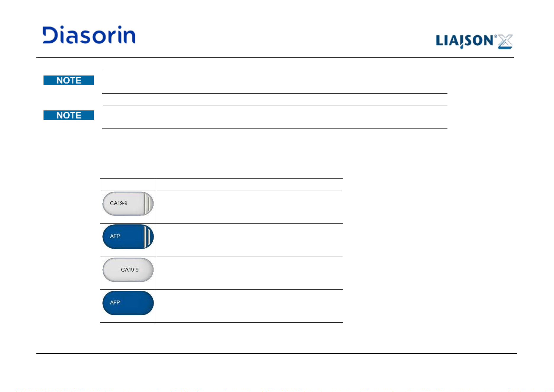
5 Use of the System
LIAISON XL - Instructions for use Page 5-65
Rev. L
It is not possible to create a worklist for selected samples and controls at the same time. Select and work up samples
separate from calibrators.
It is possible to select and work up several samples or calibrators. Additionally click on the Lock button to use the
multiple selection function.
8. Select an assay group in the Assay Selection in Group selection box in the Selection sub tab.
9. Click on the desired assay button to select one or more assays.
Use the arrows next to the assays to show all assays of the group.
Style
Description
The assay is:
• currently not loaded on the machine
• not assigned to the selected sample
The assay is:
• currently not loaded on the machine
• assigned to the selected sample
The assay is:
• currently loaded on the machine
• not assigned to the selected sample
The assay is:
• currently loaded on the machine
• assigned to the selected sample
Table 5-13: Assay status
5 Use of the System
Page 5-66 LIAISON XL - Instructions for use
Rev. L
As soon as a test is started, it will no longer be selected and may be assigned again, even if the previous test is still
running
10. Select a profile (contains several assays).
Use the arrows next to the profiles to show all profiles.
11. There is the possibility to assign one or more dilution factors to the assigned assays in the Dilution group (see chapter 6.3.1.1).
12. There is the possibility to change the number of replicates to the assigned assays in the Replicates group (see chapter 6.3.1.1).
13. Assign the other samples with assays in the same manner.
14. There is the possibility to specify patient personal information for every sample in the Demographics group (see chapter 6.3.1.1).
15. Click on the Store button to confirm the assignment.
The LIAISON
®
XL software returns to the Samples display and shows the assigned assays in the Pending column.
5.6.3 Load Controls and Assign to Assays
Note the safety notes (see chapter 5.7)!
Before the control is utilized by the user, it must first be prepared. The instruction on the packaging box must be strictly followed.
• Check that the control volume is sufficient to run the required amount of tests (as described in the "Instructions For Use" on the kits being
used).
• Check the control specific Instruction For Use for control specific preparation.
Before controls can be used, the LIAISON
®
XL system must recognize the controls.
1. Click on the Definitions main category tab.
2. Click on the Control sub category tab, see chapter 6.6.2.
Preparation
Definition
5 Use of the System
LIAISON XL - Instructions for use Page 5-67
Rev. L
3. For DiaSorin controls, click on the Scan button to open the Control Scan Dialog.
For controls not provided with the 2 dimensional barcode, it is possible to define the controls manually: see chapter 6.6.2
4. Scan the bar-code of the control(s) with the provided external bar-code scanner.
5. Click on the Ok button.
The LIAISON
®
XL system shows the control(s) in the controls table.
Do note remove the external barcode scanner while operating.
1. Load controls in the same way as patient samples (see chapter 5.6.1). The upper case conversion is not performed.
The field Type in the samples table shows a special symbol for controls.
2. When using non bar-coded control tubes or tubes with unreadable bar codes, the control ID's (SID's)/control name must be chosen
manually:
• Select the desired position in the table.
• Click on the Control button.
• Select the desired control name entry.
Only defined controls may be selected (see chapter 6.6.2).
Note: in case two controls have been defined with the same name, the system proposes the control that expires later.
• Click on the Store button.
The LIAISON
®
XL system adds the control ID from the chosen control name automatically to the SID field.
3. Assign controls in the same way as patient samples (see as described in chapter 5.6.2).
Do not mix controls and patient samples at assay assignment.
Loading
Assigning
5 Use of the System
Page 5-68 LIAISON XL - Instructions for use
Rev. L
5.7 Integrals, Calibrators, Ancillary reagents
See Biological safety in chapter 1.8.6.
Do not use reagents that have not been authorized for the LIAISON
®
XL system!
It is prohibited under any circumstances to change the components of one reagent to another even if the
reagents contain the same lot number.
• Failure to follow instructions “on the box” may result in rapid deterioration of reagent life or even
immediate expiration of reagent components.
• Handling of Reagent Integrals must be followed according the the Assay IFU’s.
• In order to avoid system delays and damage to Disposable Tips all caps must be removed from the
reagent tubes or bottles before introduction into the analyzer.
• In order to avoid tipping over and spilling of bottles or tubes racks must be inserted carefully.
5 Use of the System
LIAISON XL - Instructions for use Page 5-69
Rev. L
• Only tubes or bottles of the same type may be used for each rack, to avoid problems during the
aspiration of liquids. The tube or bottle type must be approved for the relevant rack.
• Always insert or remove the racks/integrals into the rack system with the handle.
• Never load more than one rack or integral at a time! For proper bar-code identification the racks must be
loaded one after the other, as indicated by the LEDs.
• Bar-code labels on integrals, ancillary reagents and starters are not used in the LIAISON
®
XL system.
• Note the Rack Log field for information about a loaded or selected rack (e.g. errors, empty positions).
5.7.1 Load Integrals
Before an integral is utilized, it must first be prepared. The instructed markings on the packaging box of the integrals must be strictly followed.
1. Remove the desired integral from the refrigerator keeping the integral in an upright position at all times.
2. Open the shipping box containing the integral and remove the integral.
3. Visually inspect the integral vials for leaking at the membrane seals or elsewhere. If the vials are found to be leaking, the local customer
service should be notified immediately.
4. Visually inspect the integral vials for bubbles. If bubbles are present the integral can not be immediately used. The integral must either set
until all bubbles resolve, or the bubbles must be removed before usage. (If bubbles are removed, it is important not to cross contaminate
vials)
5. Carefully remove the sealing flap of each vial by pulling the tab of the seal across the membrane in a slow fluid motion (pull only the tab in
order to prevent cross-contamination of the reagent integral vials).
6. Remove all liquid from the surfaces of the membranes to prevent cross contamination of the reagent integral vials.
7. Prepare the integral according to the related assay Instruction For Use.
Integral
Preparation
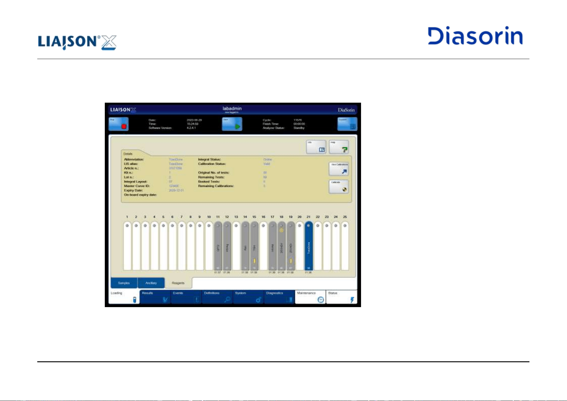
5 Use of the System
Page 5-70 LIAISON XL - Instructions for use
Rev. L
1. Insert the integral into the integrated re-suspension tool (see chapter 4.1.2) and wait 30 seconds (unless otherwise specified in kit IFU).
2. Open the reagent loading bay flap.
The software will automatically show the Reagents sub category tab of the Loading main category tab.
Figure 5-38: Sub category Reagents
Loading
5 Use of the System
LIAISON XL - Instructions for use Page 5-71
Rev. L
Function
Description
Calibrate
Starts the calibration of a selected integral.
For assays that share calibration within kit lot, this calibration will be available for all integrals of
that kit lot, no matter if loaded on-board or not. If the calibration cannot be started (e.g. external
calibrators not loaded) a pop-up will inform the user. In this case, no calibration will be created and
no jobs will be scheduled.
View
Calibrations
Shows the calibration dialog and selects the valid calibration for the selected integral, if any.
Info
Opens the Online Help and displays the documents related to the selected integral.
Standard buttons
For standard buttons (e.g. arrow buttons, lock, Print) see chapter 6.1.
Table 5-14: Functions of the Reagents sub category
Function
Description
1 ... 25
Shows the integrals in the reagent loading bay lanes. Click on a loaded integral to show details
(see 'Group Details').
Table 5-15: Functions of the Integrals group
Function
Description
Abbreviation
Abbreviation of the assay.
Article No.
Identification code of the selected integral that allows the LIAISON
®
XL system to associate the
integral to an assay.
Booked Tests
Assigned but not started tests.
Calibration
Status
Status of the calibration (e.g. valid, not valid).
Expiry Date
Date and time when the reagent integral will expire. Note: this is the last day when that reagent
integral is allowed to beused.
Integrals Group
Details Group
5 Use of the System
Page 5-72 LIAISON XL - Instructions for use
Rev. L
Integral Layout
Parameter that allows the LIAISON
®
XL system to identify the geometric characteristics of the
integral
Integral Status
Status of the integral availability:
• Online: The integral is useable
• Offline: The integral cannot be used. The abbreviation is shown in grey.
Possible reasons:
• No liquid found.
• The expiration date is exceeded.
• The reagent has a data recognition issue.
• The compatible assay protocol version is not loaded.
Kit No.
Kit number of the reagent integral.
LIS alias
Assay name on the LIS system.
Lot No.
Lot number of the reagent integral.
Master Curve ID
The ID of the master curve used for this reagent integral.
On-board expiry
date
Last date when the reagent integral can be used once it has been inserted on-board.
Original No. of
tests
Max. number of tests with a new integral.
Remaining
Calibrations
Remaining number of calibrations.
Remaining
Tests
Remaining number of determinations for the selected integral.
The number is updated (decremented by one) as soon as the first aspiration event for a
determination occurs.
Table 5-16: Functions of the Details group
5 Use of the System
LIAISON XL - Instructions for use Page 5-73
Rev. L
3. Insert the first required integral into an empty lane of the reagent loading bay.
The LIAISON
®
XL software reads the RFID tag of the integral and shows the information about the integral on the display.
4. Load the other required integrals in the same manner following steps 1-3.
5. Close the reagent loading bay flap.
6. Check all loaded integrals (see chapter 5.7.1.1).
5.7.1.1 Check Integrals
Check the loaded integrals to ensure that:
• No load error (RFID reading error) occurred
• Integral to be used has a valid calibration status
• The number of remaining tests is sufficient
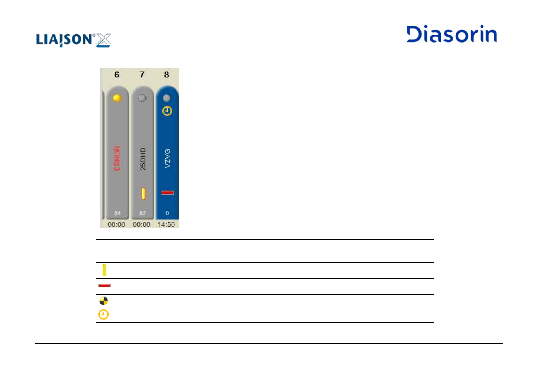
5 Use of the System
Page 5-74 LIAISON XL - Instructions for use
Rev. L
Lane number
Assay name or ERROR
Calibration status (see table below)
Number of remaining tests
Agitation countdown time:
The agitation countdown time starts with 15:00 min. and stops at 00:00 min. When it reaches 00:00, the integral
can be used (unless otherwise stated in the kit IFU).
Symbol
Description
no symbol
No specific symbol is shown if the integral has a valid calibration.
A yellow bar indicates that an expired calibration is present.
A red bar indicates that no valid calibration is present.
A calibration is ongoing for the integral.
The integral has the onboard expiration date overdue.
Table 5-17: Calibration status
5 Use of the System
LIAISON XL - Instructions for use Page 5-75
Rev. L
The symbol shall be considered effective only after the Finish time will be displayed on the header
(see chapter 6.2).
5.7.1.2 Particular Aspects of Loading Reagents in Combi-Assays
When inserting the reagent integral of a combi-assay followed by the assignment of this assay to a sample, more measuring results can be
obtained: those of the combi-sons and the one of the combi-assay.
5.7.1.3 Lot Binding (Lot Locking)
An assay may require more than one integral for a run. The LIAISON
®
XL system shows the binding between the integrals in the Reagents
sub category. When selecting one integral, the other compatible integrals will be marked with a blue frame.
5.7.2 Calibrate Integrals
Refer to the safety notes (see chapter 5.7)!
A calibration cannot be started if any of the following occurs:
• another calibration is ongoing for the same integral
• another calibration is ongoing for another integral of the same lot (if that assay shares the Working Curve)
• the calibrators are external and not present onboard
• starters, calibrators, reagents are missing or empty
• starters or reagents are expired
5 Use of the System
Page 5-76 LIAISON XL - Instructions for use
Rev. L
Before an integral is utilized, it must first be prepared. The instructed markings on the packaging box of the integrals must be strictly followed.
1. Remove the desired integral from the refrigerator keeping the integral in an upright position at all times.
2. Open the box containing the integral and remove the integral.
3. Visually inspect the integral vials for leaking at the membrane seals or elsewhere. If the vials are found to be leaking, the local customer
service should be notified immediately.
4. Visually inspect the integral vials for bubbles. If bubbles are present the integral can not be immediately used. The integral must either sit
until all bubbles resolve, or the bubbles must be removed before usage. (If bubbles are removed, it is important not to cross contaminate
vials).
5. Carefully remove the sealing flap of each vial by pulling the tab of the seal across the membrane in a slow fluid motion (pull only the tab in
order to prevent cross-contamination of the reagent integral vials).
6. Remove all liquid from the surfaces of the membranes to prevent cross contamination of the reagent integral vials.
7. Prepare the integral according to the related assay Instruction For Use.
1. Load the integral (see chapter 5.7.1)
2. Load additional calibrators in the same way as patient samples (see chapter 5.6.1).
The field Type in the samples table shows a special symbol for calibrators.
3. Click on the Reagents sub category tab of the Loading main category tab.
4. Select the affected integral in the Reagents sub category.
5. Click on the Calibrate button.
The calibration will start automatically.
When the calibration is completed, it will be automatically accepted or rejected.
6. When the calibration is completed, check if the calibration status of the affected integral is valid.
If not, exchange the integral.
Preparation
Loading
5 Use of the System
LIAISON XL - Instructions for use Page 5-77
Rev. L
• Select the affected integral in the Reagents sub category and click on the View Calibrations button.
or
• Click on the Calibrations sub category tab of the Results main category tab.
• All calibrations (valid, failed, expired…) are stored on the system database: See Calibrations sub category tab
of the Results main category tab (chapter 6.4.7).
• A sample test can be performed without a valid calibration: in this case, only RLU results will be given; the
system will automatically assign a dose to all sample results performed within the last 18 hours that have an RLU
and not a dose.
5.7.3 Load Ancillary reagents
Refer to the safety notes (see chapter 5.7)!
Before the ancillary reagents are utilized by the user, they must first be prepared. The preparation includes also the pre-storage.
The instructed markings on the packaging box must be strictly followed.
1. Remove the desired ancillary reagent from the refrigerator keeping it in an upright position at all times.
2. Open the box containing the ancillary reagent and remove it.
3. Visually inspect the ancillary reagent for leaking. If any leaking is found, the local customer service should be notified immediately.
4. Visually inspect the ancillary reagent for bubbles. If bubbles are present, the ancillary reagent can not be immediately used. The ancillary
eagent must either set until all bubbles resolve, or the bubbles must be removed before usage.
5. Prepare the ancillary reagent according to the related assay Instruction For Use.
Calibration
Report
Preparation
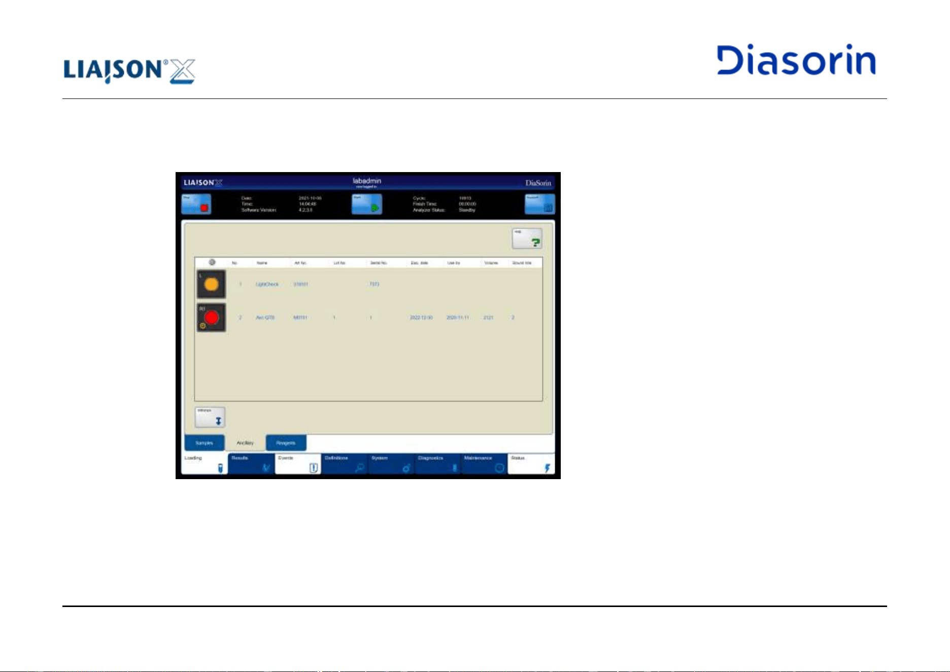
5 Use of the System
LIAISON XL - Instructions for use Page 5-79
Rev. L
Function
Description
Withdraw
If it is necessary to remove the ancillary rack during a run, press this button to suspend the
pipettor access. Insert the furthermore used ancillaries as soon as possible
Note: this could lead to test failures.
Standard buttons
For standard buttons (e.g. arrow buttons, lock, Print) see chapter 6.1.
Table 5-18: Functions of the Ancillary sub category
Column
Description
No.
Position of the ancillary reagent in the ancillary rack (1 to 4).
Name
Name of the ancillary reagent.
Art No.
Article number of the ancillary reagent (the color represents the cap color).
Lot No.
Lot number of the ancillary reagent.
Serial No.
Serial number of the ancillary reagent.
Exp. date
Date and time when the ancillary reagent will expire.
Use by
Onboard stability expiration date.
Note: if the Ancillary has the onboard expiration date overdue an additional symbol is displayed on
Ancillary representation:
Volume
Available liquid volume in the bottle.
Bound lots
If there is an entry: It is only possible to use integrals of the related assay with the reported lot
number.
Table 5-19: Columns of the Ancillary sub category table
Some fields may be empty for ancillary reagents not to be used during a routine (i.e. Light Check).
5 Use of the System
Page 5-80 LIAISON XL - Instructions for use
Rev. L
If an ancillary reagent is off-line, the description text is displayed in grey.
Possible reasons:
• No liquid found
• The expiration date is exceeded.
• The ancillary reagent has a data recognition issue.
3. Remove the ancillary rack (see chapter 4.2.6).
4. Place the ancillary reagent in the ancillary rack.
5. Insert the ancillary rack into the left lane of the reagent loading bay.
The LIAISON
®
XL software reads the RFID tag of the ancillary reagent and shows the information on the display.
6. Close the reagent loading bay flap.
See chapter 5.6.1.1 for details about loading errors.
Off-line Status
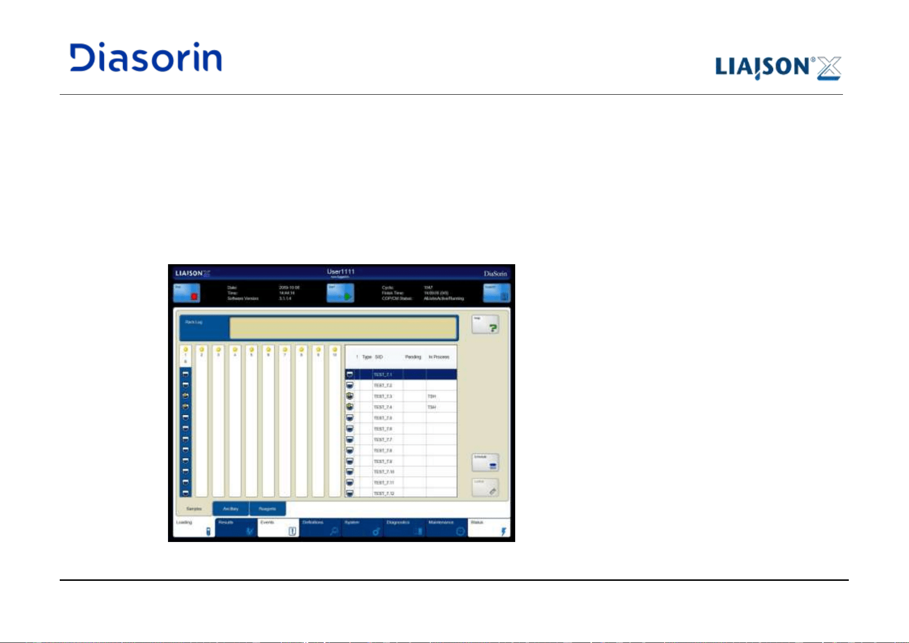
5 Use of the System
LIAISON XL - Instructions for use Page 5-81
Rev. L
5.8 Start Worklist
After the checking, loading and assigning of all resources, the LIAISON
®
XL system can start the preparation and evaluation of the samples.
1. Click on the Start button in the header.
The LIAISON
®
XL system starts with the worklist.
2. Click on the Loading main category tab.
3. Click on the Samples sub category tab.
Processed samples are marked with a symbol and the assay names are shown in the In Process column of the table. See chapter 6.3.1
for all details.
Figure 5-40: Samples display - running worklist
Procedure
5 Use of the System
Page 5-82 LIAISON XL - Instructions for use
Rev. L
5.9 Results
On the LIAISON
®
XL system, it is not necessary to wait for the entire processing to be finished to view the results. As soon as the processing
of one patient sample test, calibration, or control is finished, the system generates the result for it.
The completed results can be accessed via the main category Results as well as its several sub categories.
Sub Category
Description
Procedure
Further Details
All
The sub category All shows all entries of applied,
started, and finished worklists.
-
chapter 6.4.1
Done
The sub category Done shows only entries of
finished worklists with status Done.
chapter 5.9.1
chapter 6.4.4
Failed
The sub category Failed shows only entries of
finished worklists with status Failed.
chapter 5.9.2
chapter 6.4.6
Calibrations
The sub category Calibrations shows only
calibration entries (either valid, expired and failed
calibrations).
chapter 5.9.3
chapter 6.4.7
Controls
The sub category Controls shows the results of the
controls.
chapter 5.9.4
chapter 6.4.8
Table 5-20: Sub categories of the main category Results featuring completed results
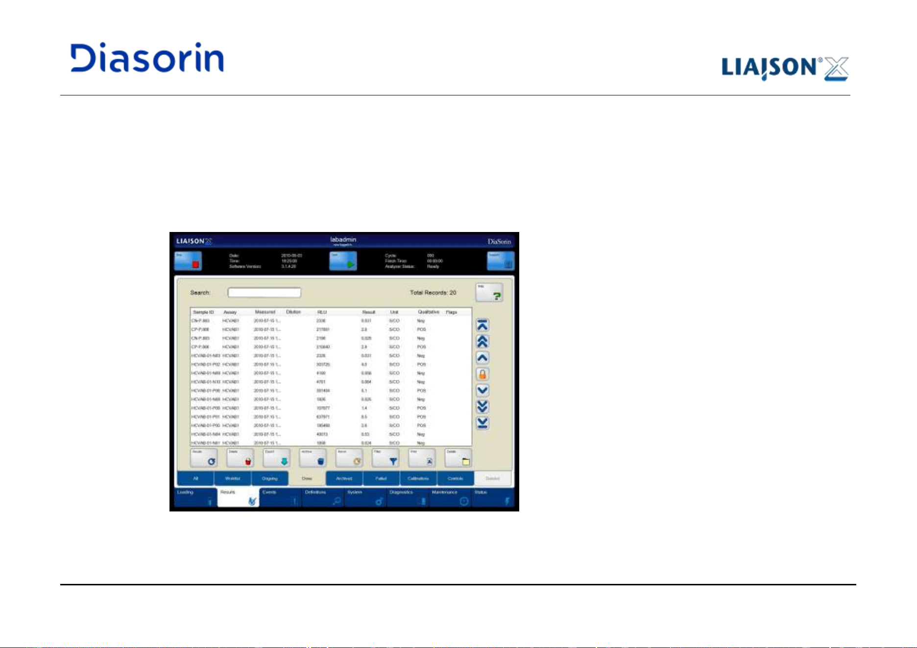
5 Use of the System
LIAISON XL - Instructions for use Page 5-83
Rev. L
5.9.1 Results of Patient Sample Tests (Status Done)
Use the sub category Done to show only patient sample entries of finished tests with status Done.
1. Click on the Results main category tab.
The LIAISON
®
XL software shows the sub category All.
2. Click on the Done sub category tab (see also chapter 6.4.4).
Figure 5-41: Sub category Done
Procedure
5 Use of the System
Page 5-84 LIAISON XL - Instructions for use
Rev. L
Function
Description
Archive
Archives the currently selected entries. The archived entries will be shown in the sub category
Archived
Note: This button is available only if automatic archiving is not enabled.
Delete
Deletes one or more entries (see chapter 6.4.1.4). The deleted entries get the status Deleted and
will be shown in the sub category Deleted.
Details
Opens the Result Details display for the selected entry (see chapter 6.4.1.3).
Export
Opens the Export display to export one or more entries to a text file (see chapter 6.4.1.2).
Filter
Opens the Select Filter display (see chapter 6.4.1.5).
Recalc
Recalculates the currently selected entries, using the most recent calibration for the assigned
assay.
Rerun
Reruns all or only the selected entry/entries.
Standard buttons
For standard buttons (e.g. arrow buttons, lock, Print) see chapter 6.1.
Table 5-21: Functions of the Done sub category
The usage of the Recalc feature may lead to modifications of already reported results: use it only in accordance with
laboratory procedures and local regulations.
If using the Recalc feature when no valid but expired calibrations are available, the system may use any calibration
among the expired calibrations to calculate the dose.
5 Use of the System
LIAISON XL - Instructions for use Page 5-85
Rev. L
Column
Description
Sample ID
Shows the sample ID.
Assay
Shows the assigned assay.
Measured Date
Result date and time.
Dilution Factor
Multiplication factor for the result (only for diluted tests).
RLU
Shows the raw result (in Relative Light Units).
Result
Shows the dose result in user units.
Unit
User defined units.
Qualitative
Label
Shows the result as qualitative evaluation (e.g. positive, negative etc.)
Flags
List of all flags. For details about the flags see chapter 5.9.5.
Table 5-22: Standard columns of the “Done” samples table
3. Pay attention to the Flags column!
See chapter 5.9.5 for the used flag abbreviations.
Dose calculation will be done automatically by the system as soon as a calibration is successful performed, provided
that the following conditions are met:
• the samples are successfully analysed but without a dose (i.e. in status Measured),
• the samples were run with the same kit (if the curve is not shared) or with the same lot (if the curve is shared),
and
• the samples were run not before 18 hours (after sample RLU result is available).
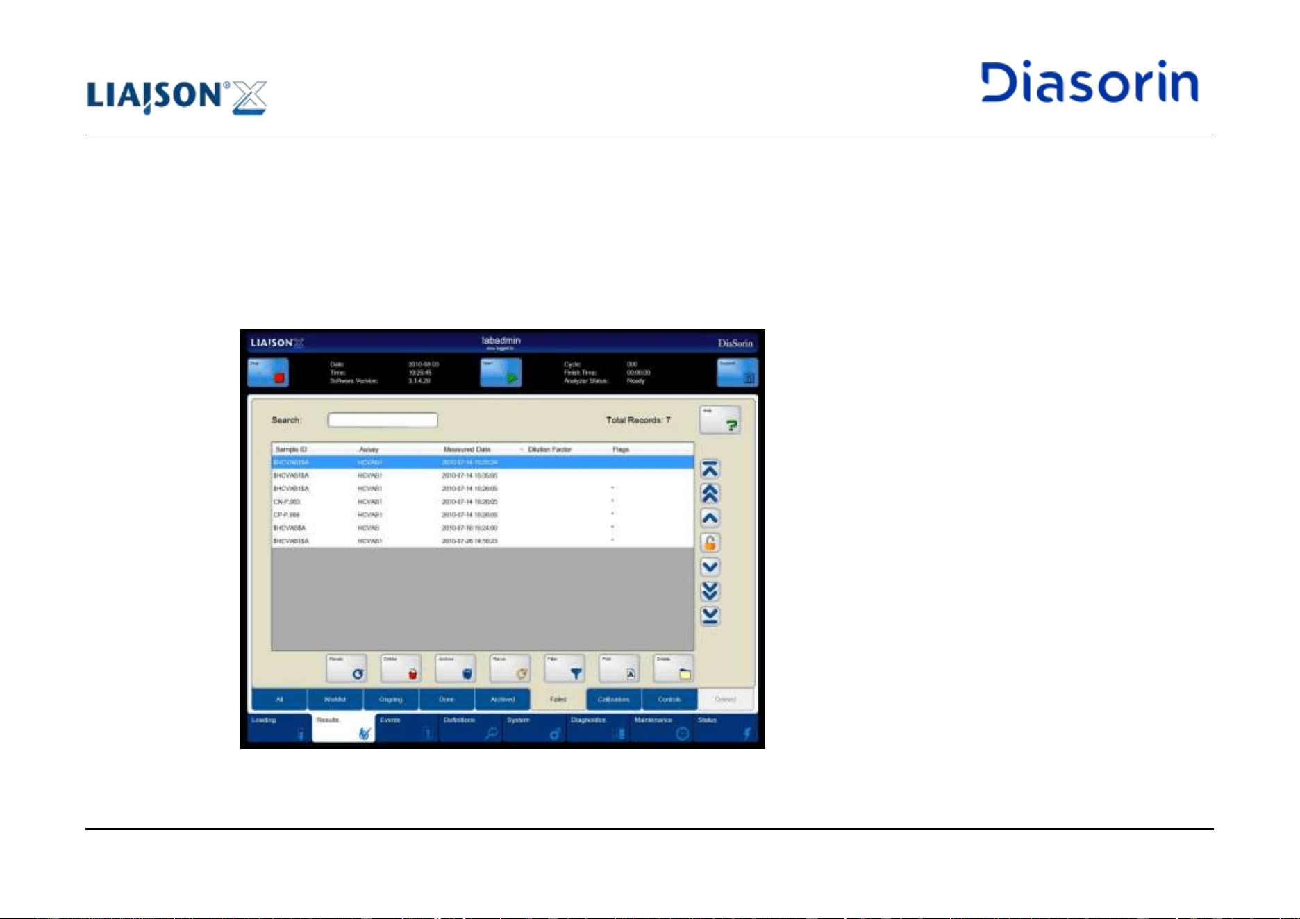
5 Use of the System
Page 5-86 LIAISON XL - Instructions for use
Rev. L
5.9.2 Results of Patient Sample Tests (Status Failed)
Use the sub category Failed to show only patient sample entries of finished tests with status Failed.
1. Click on the Results main category tab.
The LIAISON
®
XL software shows the sub category All.
2. Click on the Failed sub category tab (see also chapter 6.4.6).
Figure 5-42: Sub category Failed
Procedure
5 Use of the System
LIAISON XL - Instructions for use Page 5-87
Rev. L
Function
Description
Archive
Archives the currently selected entries. The archived entries will be shown in the sub category
Archived
Note: This button is available only if automatic archiving is not enabled.
Delete
Deletes one or more entries (see chapter 6.4.1.4).
Details
Opens the Result Details display for the selected entry (see chapter 6.4.1.3).
Filter
Opens the Select Filter display (see chapter 6.4.1.5).
Recalc
Recalculates the currently selected entries, using the most recent calibration for the assigned assay.
Rerun
Reruns the selected routine
Standard buttons
For standard buttons (e.g. arrow buttons, lock, Print) see chapter 6.1.
Table 5-23: Functions of the Failed sub category
The usage of the Recalc feature may lead to modifications of already reported results: use it only in accordance with
laboratory procedures and local regulations.
If using the Recalc feature when no valid but expired calibrations are available, the system may use any calibration
among the expired calibrations to calculate the dose.
Column
Description
Sample ID
Shows the sample ID.
Assay
Shows the assigned assay.
Measured Date
Result date and time.
Dilution Factor
Multiplication factor for the result (only for diluted tests).
Flags
List of all flags. For details about the flags see chapter 5.9.5.
Table 5-24: Standard columns of the “Failed” samples table
5 Use of the System
Page 5-88 LIAISON XL - Instructions for use
Rev. L
3. Perform the next steps accordingly to the laboratory processes:
• Details: Shows details for a selected sample entry.
• Recalc: Recalculates the currently selected entries.
• Rerun: Reruns all or only the selected entry/entries.
5.9.3 Results of Calibrations
Use the sub category Calibrations to show only entries of all calibrations.
1. Click on the Results main category tab.
The LIAISON
®
XL software shows the sub category All.
2. Click on the Calibrations sub category tab (see also chapter 6.4.7).
3. Pay attention to the Status column!
See chapter 6.4.7 for the used status abbreviations (Created, Failed, Invalid, Valid, Expired, NotUsed).
5.9.4 Results of Controls
Use the sub category Controls to show only entries of all controls.
1. Click on the Results main category tab.
The LIAISON
®
XL software shows the sub category All.
2. Click on the Controls sub category tab (see also chapter 6.4.8).
3. Pay attention to the Flags column!
See chapter 5.9.5 for the used flag abbreviations.
Procedure
Procedure
5 Use of the System
LIAISON XL - Instructions for use Page 5-89
Rev. L
5.9.5 List of Flags
A flag on results indicates that something happened during the run that may have affected the result on this sample.
The system will not report results in case of detected process anomalies.
Not reported results carry flags in order to describe the process anomalies for which that result was not reported.
Reported results may carry flags in order to inform users about the special conditions under which that result was
reported.
Each result flag may belong to one of two tables.
• If a flag from the ”invalidating flags” table is set, then the result is not reported;
• If a flag from the “informative flags” table is set, then the result is reported.
The column “Retry” tells whether a replicate may be retried without user invention or not. If it is not retried, it is set to "Failed". If it is retried
unsuccessfully a pre-defined number of times, it is also set to Failed. The retry feature is configurable by local service support.
The column “Applies to” defines to which Result the Flags are applied:
• R: Replicate,
• W: WorkOrder (entire sample test, in case of 2 or more replicates), and
• C: Combi Assay.
The Column “Inherits” defines which result inherits the flag.
5 Use of the System
Page 5-90 LIAISON XL - Instructions for use
Rev. L
Abbr.
Description
Explanation
Retry
Applies to
Inherits
*
Agitation speed out of
range.
The magnetic particel agitation was out of range while pipetted.
No
R
W,C
*
Aspiration plausibility
failure
One aspiration did not occur in the defined time slot.
No
R
W,C
*
Cycle occupation failure
(normal, dilution)
The system detected a conflict in scheduled activities.
Yes
R
W,C
*
Disposable tip not present.
The system did not have disposable tips available.
Yes
R
W,C
*
Disposable Tip Pickup
failure
The system could not pick a disposable tip assumed available.
Yes
R
W,C
*
High background in PMT.
Too high noise in the Reader
No
R
W,C
*
Incubator temperature out
of range.
Incubator temperature was out of range when the test was
processed.
No
R
W,C
*
Internal failure detected.
An internal error occurred.
No
R
W,C
*
Job scheduling failure
A job scheduling failure occurred.
Yes
R
W,C
*
Liquid Container empty.
A liquid container was empty.
No
R
W,C
*
Measurement Chamber
failure
The system detected an error in the Reader.
Yes
R
W,C
*
Mechanical error.
A mechanical error occurred on the system.
No
R
W,C
*
No cuvette available
No cuvette was available to process the job.
Yes
R
W,C
*
No Mitigation Step
performed
No successful mitigation was performed
Yes
R
W,C
*
Reagent pipetting step not
executed.
A reagent was not pipetted (e.g. pipettor was paused).
No
R
W,C
*
Sample pipetting step not
executed.
A sample was not pipetted (e.g. pipettor was paused).
No
R
W,C
Invalidating Flags
5 Use of the System
LIAISON XL - Instructions for use Page 5-91
Rev. L
Abbr.
Description
Explanation
Retry
Applies to
Inherits
*
Pipettor offline.
The test could not be pipetted when needed.
No
R
W,C
*
Waste container full.
Processing aborted due to full waste container.
No
R
W,C
*
Starter Dispense
Verification failure
The liquid volume aspirated from the cuvette after the
measurement step was lower than expected.
Yes
R
W,C
*
Starter lot change
A replicate could not start due to a starter lot change meanwhile
occurred.
No
R
W,C
*
Starter reagent
temperature out of range.
A scheduled Starter prime could not occur.
No
R
W,C
*
Starter prime not
performed.
Starter reagent temperature was out of range when the test was
processed.
Yes
R
W,C
*
Timing violation.
The pipettor was overloaded.
No
R
W,C
*
User requested abort
The test was aborted as per user request.
No
R
W,C
*
Washer aspiration failure.
An aspiration failure was detected in the washer.
Yes
R
W,C
C
No calibration
No usable calibration found.
No
R
W,C
D
Overdiluted
The sample was over diluted. (Only for samples with sample
specific dilution)
No
R
W,C
M
Mathematical error
Math error occurred while calculating dose.
No
R,W,C
W
R
Ancillary not present.
A needed ancillary was not found (vial not present or offline).
No
R
W,C
R
Reagent depleted.
The reagent pipettor arm found no liquid.
No
R
W,C
R
Reagent integral not
present.
A needed integral was not found (integral not present or offline).
No
R
W,C
R
Reagent integrity failure.
An aspiration or dispense failure was detected by the reagent
pipettor.
No
R
W,C
S
Clot in sample detected
An aspiration failure was detected by the sample pipettor
No
R
W,C
5 Use of the System
Page 5-92 LIAISON XL - Instructions for use
Rev. L
Abbr.
Description
Explanation
Retry
Applies to
Inherits
S
Sample depleted.
The sample pipettor arm found no liquid.
No
R
W,C
S
Sample integrity failure.
An aspiration or dispense failure was detected by the sample
pipettor.
No
R
W,C
S
Sample not present.
The sample was not found (tube not present or offline).
No
R
W,C
X<
Combi Son Below Assay
Range
Any combi son is below the assay range.
No
C
X>
Combi Son Above Assay
Range
Any combi son is above the assay range.
No
C
XM
Combi Son has
mathematical error
Any combi son has a math error in dose calculation.
No
C
Z
Divided by zero
For calculation of a combi assay result a division by zero
occurred
No
C
Table 5-25: List of invalidating flags (in alphabetical order)
5 Use of the System
LIAISON XL - Instructions for use Page 5-93
Rev. L
Abbr.
Description
Explanation
ApTo
Inher
&
Rerun
This Result matched a Rerun Rule (for patient samples only).
W
<
Below assay range
The calculated dose is below the assay range
R,W,C
>
Above assay range
The calculated dose is above the assay range. If the assay
range high limit is not defined, than the concentration of the last
standard may be used (depending on assays).
R,W,C
C
Calibration expired
The calibration used for calculation was expired.
R
W,C
E
Reagent On Board Stability
Expired
The used integral or ancillary had the onboard expiration date
overdue.
R
W,C
NH
Above normal range
The calculated dose is above normal range (not for calibrators
and controls).
R,W,C
NL
Below normal range
The calculated dose is below normal range (not for calibrators
and controls).
R,W,C
Q
Controls out of
manufacturer range
Only for samples.
Not generated if the range is empty, for “precision” controls -
based on last performance of any “control name” defined for that
assay.
R,W,C
QE
Control expired
The control used was expired
R
W,C
QH
QC above manufacturer
range
Only for controls.
In case the control is above assay range, this flag is generated
as well.
Not generated if the control range is empty, for “precision”
controls.
R,W,C
Informative Flags
5 Use of the System
Page 5-94 LIAISON XL - Instructions for use
Rev. L
Abbr.
Description
Explanation
ApTo
Inher
QL
QC below manufacturer
range
Only for controls.
In case the control is below assay range, this flag is generated
as well.
Not generated if the control range is empty, for “precision”
controls.
R,W,C
RM
Recalculated
The result was recalculated upon user request.
R
W,C
UH
QC above user range
Only for controls.
In case the control is above assay range, this flag is generated
as well.
Not generated if the control range is empty, for “precision”
controls.
R,W,C
UL
QC below user range
Only for controls.
In case the control is below assay range, this flag is generated
as well.
Not generated if the control range is empty, for “precision”
controls.
R,W,C
X&
Son Rerun
A combi son matched a Rerun Rule (for patient samples only).
C
XNH
Son above normal range
A combi son was above the Normal Range.
C
XNL
Son below normal range
A combi son was below the Normal Range.
C
Table 5-26: List of informative flags (in alphabetical order)
For reporting purpose some flags mask some other flags, i.e. : the presence of a flag avoids another flag of lower importance.
For example, a result with flag “S” is not provided with flag “C”, even if the calibration was expired.
Flag Mask
5 Use of the System
LIAISON XL - Instructions for use Page 5-95
Rev. L
For combi assay results some flags reflected the presence of a flag into any combi son results.
The flag for a Combi Son…
… becomes the flag for its Combi Father
Math Error
Son Math Error
Below Assay Range
Son Below Assay Range
Above Assay Range
Son Above Assay Range
Below Normal Range
Son Below Normal Range
Above Normal Range
Son Above Normal Range
CausedRerun
Son CausedRerun
Table 5-27: Combi results flags
Combi Results
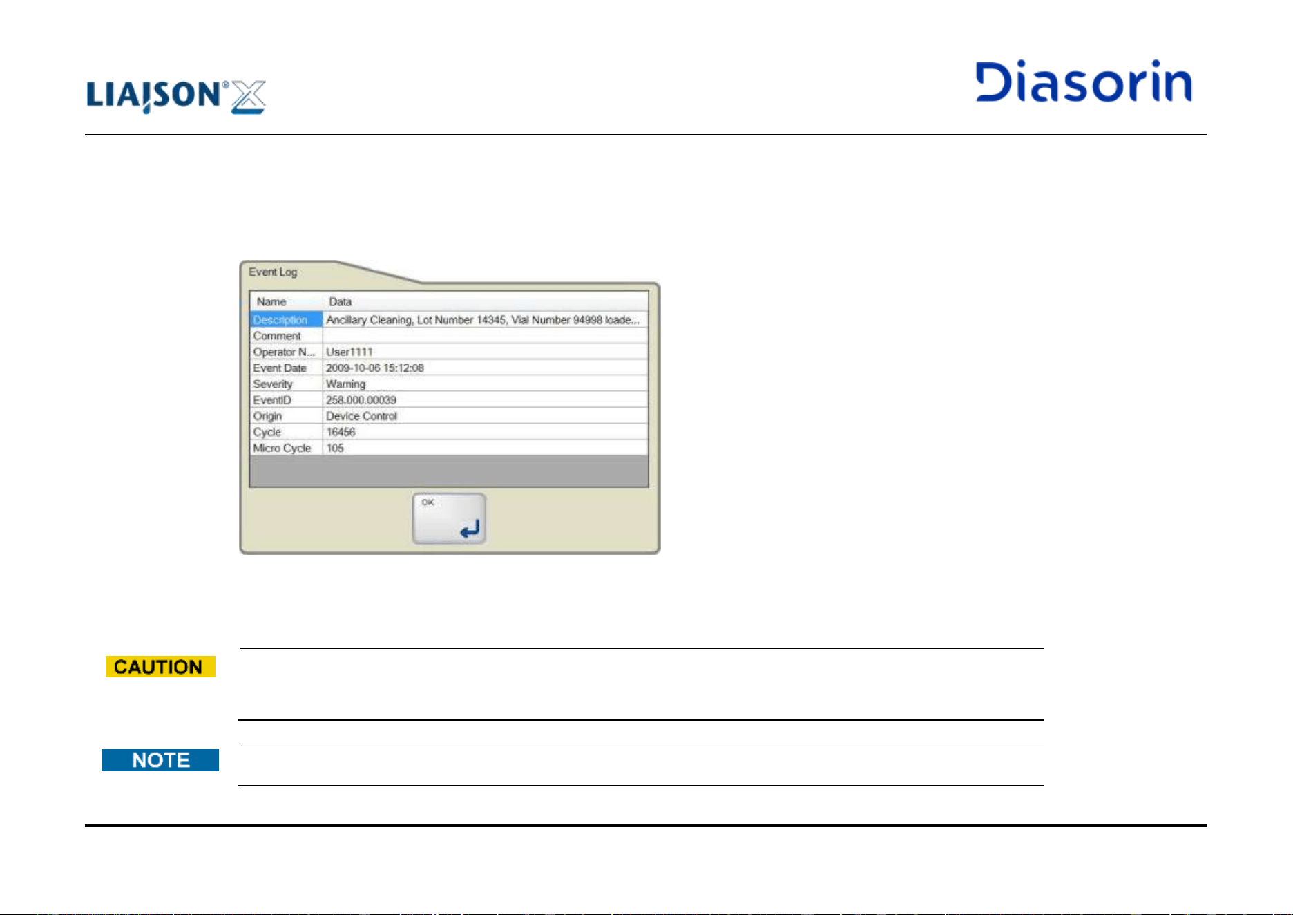
5 Use of the System
Page 5-96 LIAISON XL - Instructions for use
Rev. L
5.10 Routine errors
If an error occurs that could compromise the integrity of the system or could fail a significant amount of results, the run is automatically
stopped. A message box with a message describing the error is displayed. Error messages have to be confirmed
Figure 5-43: Event Log Message
All errors and events can be shown in chapter 6.5.
The results obtained in a routine with multiple repeated Instrument Errors should be interpreted carefully. In order to
get optimal performance of the instrument the user should highlight any anomalies / error trends and request the
advice of the Local DiaSorin Representative.
Error messages are described in chapter 9.1.
5 Use of the System
LIAISON XL - Instructions for use Page 5-97
Rev. L
If the error reoccurs, please call service.
5.11 Unloading
It is possible to unload unused sample racks or integrals. The LIAISON
®
XL system shows unused resources.
5.11.1 Unload Sample Racks
Disposal of Infectious Waste
Potential infectious material and all parts that may come in contact with potential infectious material must be
disposed according to the local and national provisions, legislation and laboratory procedures.
Error at Loading/Unloading of Racks and Samples
Improperly loaded or unloaded racks or samples may cause wrong results due to incorrect pipetting activities.
• Only load and unload racks if explicitly allowed by corresponding LED (see chapter 4.2.5).
• Only load and unload racks on the specified lanes.
Use of Racks
Remove the racks carefully out to avoid tipping and spilling of bottles or tubes.
5 Use of the System
Page 5-98 LIAISON XL - Instructions for use
Rev. L
Always remove the racks by the handle.
Never unload more than one rack at the same time.
Unload all sample racks before shutting the LIAISON
®
XL system down.
1. Observe the LEDs under the sample loading bay lanes.
2. If there are LEDs off, but the lanes are occupied, then open the sample loading bay flap.
3. Hold the handle of an unused sample rack and push the sample rack against backside. Note the audible click.
4. Remove the sample rack carefully.
5. Unload other unused sample racks.
6. Close the sample loading bay flap.
Patient Samples:
If the sample tubes are not empty and will be used at a later date:
• Cover and store the patient sample according to laboratory regulations/specifications.
If the sample tubes are empty:
• Discard tubes or bottles in an appropriate manner.
5 Use of the System
LIAISON XL - Instructions for use Page 5-99
Rev. L
Controls and Calibrators:
If the control or calibrator is not empty:
• Place the appropriate cap on the control or calibrator.
• Place the control or calibrator in a tray in an upright position (if available).
• Place the tray into the refrigerator (see storage information in the control or calibrator instruction).
• If a tray is not available, place the control or calibrator bottle into the refrigerator in a secure upright position.
If the control or calibrator is empty:
• Discard the control or calibrator in an appropriate manner.
Use of Controls and Calibrators
Do not use controls or calibrators that have not been authorized for the LIAISON
®
XL system environment.
5 Use of the System
Page 5-100 LIAISON XL - Instructions for use
Rev. L
5.11.2 Unload Integrals
Disposal of Infectious Waste
Potential infectious material and all parts that may come in contact with potential infectious material must be
disposed according to the local and national provisions, legislation and laboratory procedures.
Error at Loading/Unloading of Racks, Reagents and Samples
Improperly loaded or unloaded racks, reagents or samples may cause wrong results due to incorrect pipetting
activities.
• Only load and unload racks if explicitly allowed by corresponding LED (see chapter 4.2.6).
• Only load and unload racks on the specified lanes.
Use of Integrals
Remove integrals carefully out to avoid tipping and spilling of integrals.
Do not remove integrals still in use.
Always remove the integrals by the handle.
Never unload more than one integral at a time.
5 Use of the System
LIAISON XL - Instructions for use Page 5-101
Rev. L
1. Observe at the LEDs under the reagent loading bay lanes.
2. If there are LEDs off, but the lanes are occupied, then open the reagent loading bay flap.
3. Hold the handle of an unused integral and remove it carefully in an upright position.
4. Unload other unused integrals.
5. Close the reagent loading bay flap.
If the integral is not empty:
• Place the integral in an integral tray in an upright position (if available).
• Place the integral tray into the refrigerator (see storage information in the integral instruction for use manual).
• If an integral tray is not available, place the integral into the refrigerator in a secure upright position.
If the integral is empty:
• Discard the integral in an appropriate manner.
Use of Integrals
Do not use integrals that have not been authorized for the LIAISON
®
XL system environment.
Use of Integrals
It is prohibited under any circumstances to modify the integral setup.
5 Use of the System
Page 5-102 LIAISON XL - Instructions for use
Rev. L
5.11.2.1 Proper Storage and Handling of Integrals
Store the integral according to the related Instruction For Use.
5.11.3 Unload Ancillary Reagents
Disposal of Infectious Waste
Potential infectious material and all parts that may come in contact with potential infectious material must be
disposed according to the local and national provisions, legislation and laboratory procedures.
Error at Loading/Unloading of Racks, Reagents and Samples
Improperly loaded or unloaded racks, reagents or samples can cause wrong results due to incorrect pipetting
activities.
• Only load and unload racks if explicitly requested to do so.
• Only load and unload racks on the specified lanes.
Use of Ancillary Rack
Pull the ancillary rack carefully out to avoid tipping and spilling of bottles.
Do not remove ancillaries that are still in use.
Always remove the ancillary rack by the handle.
5 Use of the System
LIAISON XL - Instructions for use Page 5-103
Rev. L
1. Look at the left LED under the reagent loading bay lane (lane “A”).
2. If the LED is off, but the lane is occupied, then open the reagent loading bay flap.
3. Hold the handle of the unused ancillary rack and remove it carefully keeping it in an upright position.
4. Close the reagent loading bay flap.
If the ancillary reagent is not empty:
• Place the ancillary or reagent in a tray in an upright position (if available).
• Place the tray into the refrigerator (see storage information in the ancillary or reagent instruction for use manual).
• If a tray is not available, place the ancillary or reagent bottle into the refrigerator in a secure upright position.
If the ancillary or reagent is empty:
• Discard the ancillary reagent in an appropriate manner.
Use of Ancillary Reagents
Do not use ancillary reagents that have not been authorized for the LIAISON
®
XL system environment.
5 Use of the System
Page 5-104 LIAISON XL - Instructions for use
Rev. L
5.12 Shut Down/End of Day Maintenance
The LIAISON
®
XL can be left on after the routine completion without any special precautions. The system automatically
goes into a “stand-by” condition after some time of inactivity.
Shutdown might be possible in case of long period of inactivity (more than 3 weeks); please contact your local
service to arrange a dedicate service visit, therefore a service visit is needed to restart the LIAISON
®
XL analizer.
The shutdown and restart of the system from long period requires the assistance of service technical personnel.