
User Manual
Document Version: V1.0
Model: Ebyte-MDL3
Wireless: 5.8G Wi-Fi (802.11a/n/ac/ax, 20 MHz only) + Bluetooth LE (1M / 2M)
Table of Contents
1. Safety Precautions
2. Product Overview
3. Technical Specifications
4. 5.8G Wi-Fi Subsystem
5. Bluetooth LE Subsystem
6. LoRa Receive Subsystem (900 MHz / 2.4 GHz)
7. Hardware Interface
8. Software and Configuration
9. Typical Applications
10. Package and Ordering Information
11. Revision History

1. Safety Precautions
Read this manual carefully before using the Ebyte-MDL3
module. The following safety
and
regulatory rules must be observed at all times.
This module is a radio transmitting device. Before use, confirm that the product has
obtained radio type approval / certification for the target country or region.
Keep the module at least 20 cm away from cardiac pacemakers or other implanted medical
devices.
Do not use the module in locations where radio equipment is prohibited, such as gas
stations, blasting sites, or aircraft cabins.
Do not leave the RF antenna port unterminated or connected to a non-matched load while
transmitting, as this may damage the RF front end.
This module may only be integrated and tested by qualified engineers as part of a finished
product.
Only use the antenna(s) specified in this manual or approved by the manufacturer;
unauthorized antennas may violate regulatory limits.
2. Product Overview
2.1 Introduction
The Ebyte-MDL3 is a tri-mode wireless module integrating a single-band 5.8 GHz Wi-Fi
radio, a dual-rate Bluetooth Low Energy (BLE) radio, and a LoRa receive (RX-only)
subsystem. The Wi-Fi section is compliant with IEEE 802.11a, 802.11ac (Wi-Fi 5) and
802.11ax (Wi-Fi 6), and operates with a FIXED 20 MHz channel bandwidth. The Bluetooth
section supports the BLE 1M PHY and BLE 2M PHY defined by Bluetooth 5.x. The LoRa
subsystem operates on the 900 MHz and 2.4 GHz bands and is capable of receiving
broadcast messages from LoRa-based IoT devices. The module is designed for reliable
wireless connectivity in IoT, smart-home, industrial sensing and audio/video applications.
2.2 Key Features
Wi-Fi (5.8 GHz):
Standards: 802.11a,802.11n, 802.11ac, 802.11ax (Wi-Fi 6)
Fixed bandwidth: 20 MHz only (no 40/80/160 MHz bonding)
Modulation: OFDM / OFDMA; up to 1024-QAM (802.11ax)
Frequency: 5725~5850 MHz
Bluetooth LE:
Physical layers: BLE 1M PHY and BLE 2M PHY
Modulation: GFSK (1M), GFSK (2M)
Frequency: 2.402-2.480 GHz (40 channels: 3 advertising + 37
data)
LoRa Receive (900 MHz / 2.4 GHz):
- Receive-only (RX); captures broadcast/beacon frames from LoRa IoT devices
- No transmission; no LoRaWAN network association required
2.3 Applications
Smart home (gateways, cameras, lighting, sensors)
Industrial IoT (data acquisition, AGV, remote control)
Healthcare and wearable devices
Audio / video streaming (low-latency scenarios)
Battery-powered low-power wireless terminals
- LoRa IoT sensor network collector / gateway
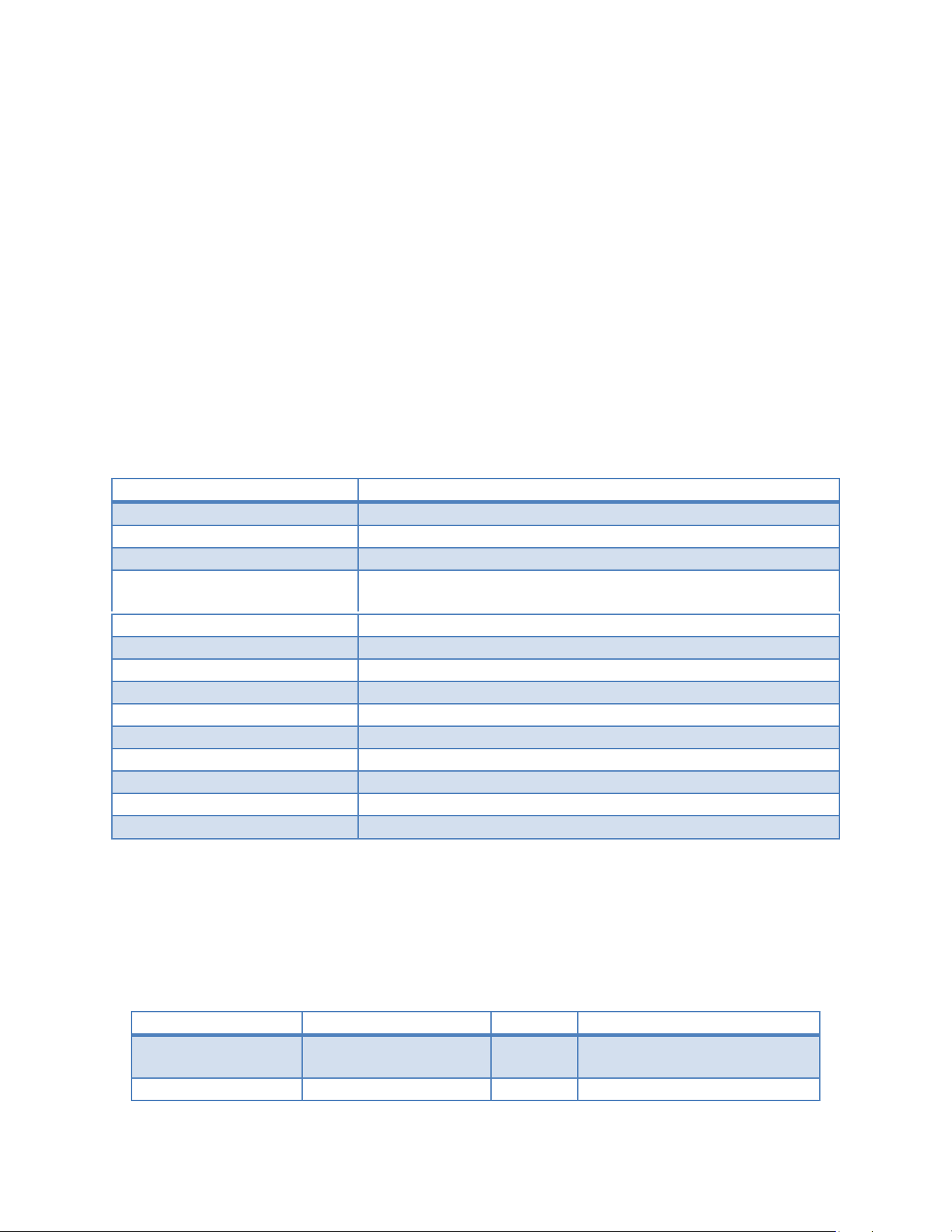
3. Technical Specifications
Item
Specification
Wireless modes
Wi-Fi 5.8G (a/n/ac/ax) + BLE (1M/2M)
Wi-Fi band
5745-5825MHz
Wi-Fi bandwidth
20 MHz (fixed)
Wi-Fi peak rate
802.11a: 54 Mbps; 802.11ac: 86.7 Mbps (1SS, SGI); 802.11ax:
143.4 Mbps (1SS, SGI)
BLE PHY
1M PHY (1 Mbps), 2M PHY (2 Mbps)
Bluetooth band
2.402-2.480 GHz
Antenna interface
Pad / on-board / IPEX
Host interface
SDIO / USB / UART
Operating voltage
16Vdc
Operating temp.
-10 C to +45 C (industrial grades available)
Storage temp.
-40 C to +85 C
Dimensions
See model datasheet
LoRa receive
900 MHz ISM and 2.4 GHz; receive only (RX), no transmit
LoRa function
Receives broadcast/beacon frames from LoRa IoT devices
Note: The rates above are theoretical peak values for a single spatial stream (1SS). Actual throughput is
affected by protocol overhead, distance and interference. Multi-stream models scale the rate linearly.
4. 5.8G Wi-Fi Subsystem
4.1 Supported Standards
Standard
Alias
Year
Note
IEEE 802.11a
Wi-Fi (5G, 1st gen)
1999
OFDM, 20 MHz only, up to 54
Mbps
IEEE 802.11n/ac
Wi-Fi 5
2013
VHT; this module limited to 20
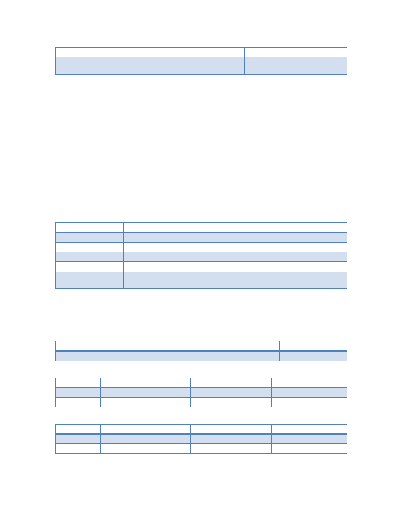
MHz
IEEE 802.11ax
Wi-Fi 6
2019
HE / OFDMA; this module
limited to 20 MHz
4.2 Bandwidth Note (Important)
This module's Wi-Fi section SUPPORTS 20 MHz BANDWIDTH ONLY. 40 / 80 / 160 MHz
channel bonding is NOT supported.
In 802.11ac / 802.11ax, the high throughput normally relies on 80/160 MHz channels.
Limited to 20 MHz, the maximum rate is bounded by the 20 MHz MCS table of each
standard (see 4.4).
The 20 MHz mode provides better wall penetration and interference margin, making it
more stable in dense, long-range or obstacle-rich deployments.
When negotiating with an AP that requests 40 MHz or wider, the module automatically falls
back to a 20 MHz connection without affecting basic connectivity.
4.3 Operating Channels (5.8G, 20 MHz)
For the China 5.8G ISM band (5725-5850 MHz), the common 20 MHz channels are:
Channel
Center Freq (MHz)
Region
149
5745
China / Global
153
5765
China / Global
157
5785
China / Global
161
5805
China / Global
165
5825
China / Global (20 MHz only in
some regions)
Multi-region versions also support UNII-1/2/3 (channels 36, 40, 44, 48, 52..., 100...). Enabling DFS channels
requires firmware support and compliance with local regulations.
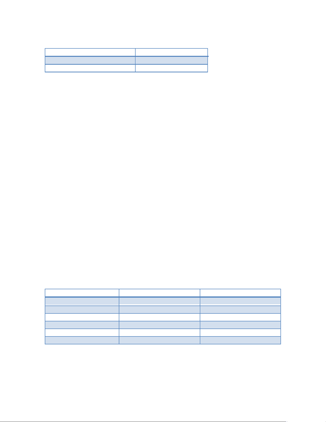
4.4 Data Rates and MCS (20 MHz, 1 Spatial Stream)
802.11a (OFDM, 20 MHz):
Rate (Mbps)
Modulation
Coding rate
6 / 9 / 12 / 18 / 24 / 36 / 48 / 54
BPSK ~ 64-QAM
1/2 ~ 3/4
802.11ac (VHT, 20 MHz, 1SS):
MCS
Modulation
Long GI (Mbps)
Short GI (Mbps)
0-8
BPSK ~ 256-QAM
6.5 - 78.0
7.2 - 86.7
9
256-QAM 5/6
78.0
86.7
802.11ax (HE, 20 MHz, 1SS):
MCS
Modulation
Long GI (Mbps)
Short GI (Mbps)
0-10
BPSK ~ 1024-QAM
8.6 - 130.3
9.5 - 143.4
11
1024-QAM 5/6
130.3
143.4
4.5 Transmit Power
Frequency
TX Power (dBm)
2.4G
2.92
5.8G
14.06
Actual values are subject to the model datasheet and must meet national EIRP limits.
4.6 Antenna
On-board PCB antenna,(BT model:LZANT-11856-A;5G model:NDMD-L3-5G-V2.0),Keep the
antenna away from metal shielding and high-speed digital traces. Replacing the antenna
model requires re-evaluation of certification.
5. Bluetooth LE Subsystem
5.1 BLE 1M PHY
Air rate: 1 Mbps
Modulation: GFSK
Symbol rate: 1 Msym/s
Longest range, lowest power, best compatibility .
Use case: sensor reporting, low-frequency control, long-range low-rate links.
5.2 BLE 2M PHY
Air rate: 2 Mbps
Modulation: GFSK,
Symbol rate: 2 Msym/s
Double throughput, half transmission time -> lower average power and lower latency.
Because energy is more concentrated, equivalent range is slightly shorter than 1M
PHY.
Use case: OTA upgrade, audio streaming, high-frequency interaction, latency-sensitive links.
5.3 BLE 1M vs 2M Comparison
Parameter
BLE 1M PHY
BLE 2M PHY
Symbol rate
1 Msym/s 2 Msym/s
Air rate
1 Mbps 2 Mbps
Application throughput
Low ~2x
TX duration
Long Short (energy saving)
Coverage
Far Slightly nearer
Typical use
Long range / low power High speed / low latency
Both PHYs can be switched dynamically within a connection via LE Set PHY without re-establishing the link.

5.4 Operating Channels
2.402-2.480 GHz, 40 channels: 37 data channels + 3 advertising channels (37/38/39 at
2402/2426/2480 MHz).
Adaptive Frequency Hopping (AFH) is used to avoid co-channel Wi-Fi interference.
6. LoRa Receive Subsystem (900 MHz / 2.4 GHz)
The Ebyte-MDL3 integrates an additional LoRa receive (RX-only) subsystem that operates
concurrently on two frequency bands: 900 MHz (e.g., 902-928 MHz ISM) and 2.4 GHz. It is
designed to receive broadcast and beacon messages transmitted by surrounding LoRa-
based IoT devices such as sensors, meters, trackers and environmental nodes, without
requiring the module to join a LoRaWAN network.
6.1 Supported Bands and Mode
- 900 MHz ISM band (region dependent, e.g., 902-928 MHz) and 2.4 GHz ISM band.
- Receive only (RX); the LoRa subsystem does not transmit.
6.2 IoT Broadcast Reception
- Captures LoRa-modulated broadcast/beacon frames from nearby IoT devices.
- Supports common spreading factors (SF7-SF12) and bandwidths (125/250/500 kHz at
900 MHz; 800 kHz / 1.6 MHz at 2.4 GHz); exact capability is model dependent.
- The host can parse the received payload to obtain the device identifier, application data,
and link quality (RSSI / SNR).
6.3 Notes
- RX-only function; it does not establish LoRaWAN connections or transmit uplinks.
- Deployment must observe the local frequency regulations applicable to the 900 MHz band.
- Antenna: use a matched 900 MHz / 2.4 GHz antenna, or a shared 2.4 GHz antenna as
specified by the hardware design.
7. Hardware Interface
The following is a generic definition; the exact pinout follows the model datasheet Pinmap.
Interface type
Description
Host interface
SDIO 3.0 / USB 2.0 / UART for Wi-Fi & BLE data
RF port
Wi-Fi: 5.8G antenna pad or IPEX; BLE: 2.4G antenna
Power
VCC 3.3 V, GND
Control pins
WL_EN, BT_EN, RESET#, WAKE

Status pins
HOST_WAKE (interrupt)
Layout recommendations:
Control RF traces at 50 ohm impedance and keep them as short as possible.
Separate digital and RF power supplies with ferrite beads / filters.
Do not route high-speed digital lines under the module; keep a solid ground plane.
8. Software and Configuration
8.1 Driver and Stack
Wi-Fi: Linux / RTOS drivers (nl80211 / vendor SDK); supports STA / AP / P2P.
BLE: Host stack (GATT / SMP / GAP) or transparent firmware (AT commands).
8.2 AT Command Examples (BLE transparent firmware)
AT+BLEINIT=1 // init BLE
AT+BLEMODE=0 // 0=peripheral, 1=central
AT+PHY=2M // set preferred PHY to 2M (1M/2M/Coded)
AT+BLENAME="MOD_TEST" // set device name
AT+ADVSTART // start advertising
8.3 Wi-Fi Configuration (20 MHz forced)
# Force 20 MHz (disable HT40 / VHT80)
iw dev wlan0 set channel 149 HT20
# Driver option: limit capability table to 20 MHz only
Because the hardware supports 20 MHz only, no extra restriction is needed to guarantee that wider
bandwidth is never enabled.
9. Typical Applications
Smart-home gateway: 5.8G Wi-Fi STA backhaul + BLE 1M for low-power sensors.
Wireless camera: 5.8G Wi-Fi ax 20M stable backhaul + BLE 2M for fast phone provisioning.
Industrial data acquisition: Wi-Fi ac 20M interference-resilient link + BLE 1M device
c
ascade.
OTA upgrade: BLE 2M PHY shortens firmware transfer time and reduces power.
Design tips: prefer 5.8G to avoid 2.4G congestion; after BLE provisioning switch to 2M PHY for speed; keep Wi-
Fi fixed at 20 MHz for stability.
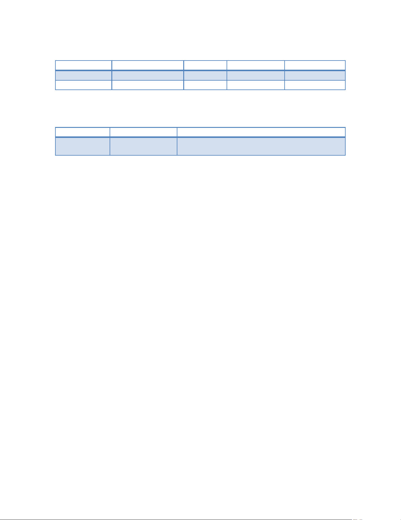
10. Package and Ordering Information
Model suffix
Wi-Fi
BLE
Antenna
Temp. grade
-A
a/n/ac/ax 20M
1M/2M
IPEX
Commercial
-I
a/n/ac/ax 20M
1M/2M
On-board
Industrial
Order by the complete model number; see the sales part-number table for details.
11. Revision History
Version
Date
Description
2026-08-03
Initial release. Covers 5.8G Wi-Fi (a/n/ac/ax,
20M) and BLE (1M/2M).
Copyright (c) Module Manufacturer. All rights reserved. Specifications are subject to change without notice; the latest
datasheet shall prevail.
FCC Statement
This device complies with part 15 of the FCC Rules. Operation is subject to the following two conditions:
(1)This device may not cause harmful interference, and (2) this device must accept any interference received, including interference that may cause
undesired operation.
Any changes or modifications not expressly approved by the party responsible for compliance could void the user''s authority to operate the
equipment.
This equipment has been tested and found to comply with the limits for a Class B digital device,pursuant to part 15 of the FCC Rules. These limits are
designed to provide reasonable protection against harmful interference in a residential installation. This equipment generates, uses and can radiate
radio frequency energy and, if not installed and used in accordance with the instructions, may cause harmful interference to radio communications.
However, there is no guarantee that interference will not occur in a particular installation. If this equipment does cause harmful interference to radio
or television reception, which can be determined by turning the equipment off and on, the user is encouraged to try to correct the interference by one
or more of the following measures:
—Reorient or relocate the receiving antenna.
—Increase the separation between the equipment and receiver.
—Connect the equipment into an outlet on a circuit different from that to which the receiver is connected.
—Consult the dealer or an experienced radio/TV technician for help.
FCC Radiation Exposure Statement
This equipment complies with FCC radiation exposure limits set forth for an uncontrolled environment . This transmitter must not be co-located or
operating in conjunction with any other antenna or transmitter. This equipment should be installed and operated with minimum distance 20cm
between the radiator& your body.

Antenna Type Maximum antenna gain
PCB
BLE :1.5dBi
5G: 2.68dBi
7. Label and compliance information
The final end product must be labeled in a visible area with the following" Contains FCC ID:2A8C3-EBYTE-MDL3”
8. Information on test modes and additional testing requirements
Host manufacturer is strongly recommended to confirm compliance with FCC requirements for the transmitter when
the module is installed in the host.
9. Additional testing, Part 15 Subpart B disclaimer
Host manufacturer is responsible for compliance of the host system with module installed with all other applicable
requirements for the system such as Part 15 B
Module integration Description
Integration instructions for host product manufacturers according to 996369 D03 OEM Manual v01r01
1. List of applicable FCC rules
CFR 47 FCC PART 15 SUBPART C&E has been investigated. It is applicable to the modular.
2. Specific operational use conditions
This module is stand-alone modular. If the end product will involve the Multiple simultaneously transmitting condition or
different operational conditions for astand-alone modular transmitter in a host, host manufacturer have to consult with
module manufacturer for the installation method in end system.
3. Limited module procedures
Not applicable
4. Trace antenna designs
Not applicable
5. RF exposure considerations
To maintain compliance with FCC’s RF Exposure guidelines, This equipment should be installed and
operated with minimum distance of 20cm from your body.
6. Antennas
This radio transmitter FCC ID:2A8C3-EBYTE-MDL3 has been approved by Federal Communications Commission to operate
with the antenna types listed below, with the maximum permissible gain indicated. Antenna types not included in this list
that have a gain greater than the maximum gain indicated for any type listed are strictly prohibited for use with this
device.