深圳市中龙通电子科技有限公司 Page
2
1.
Overview
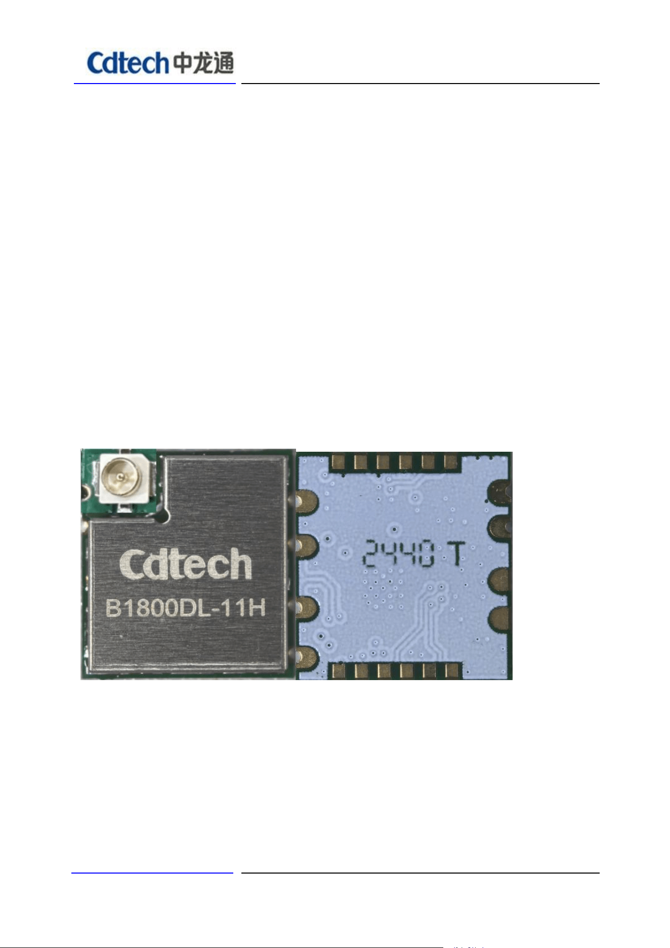
The CDW-B1800DL-11H module is a highly integrated chip 2.4GHz Wi‐Fi6, BLE5.2 for
wireless application.
2. Features
■ CMOS single‐chip fully‐integrated RF, Modem and MAC
■ Support 2.4GHz Wi‐Fi6
■ Support 20/40MHz bandwidth
■ Data rates up to 286.8Mbps@TX and 229.4Mbps@RX
■ Support STA, AP, Wi‐Fi Direct modes concurrently
■ Support STBC, beamforming
■ Support Wi‐Fi6 TWT
■ Support MU‐MIMO, OFDMA
■ Support Two NAV, Buffer Report, Spatial reuse, Multi‐BSSID, intra‐PPDU power save
■ Support LDPC
■ Support DCM, Mid‐amble, UORA
■ Support WEP/WPA/WPA2/WPA3‐SAE Personal, MFP
■ Supports USB2.0 interface
■ Integrated low power timer and watchdog
■ Supports all the mandatory and optionalfeatures of Bluetooth LowEnergy
■ Supports advanced master and slave topologies
■ Use an optimization method to assess channel quality, AFH enhancement
深圳市中龙通电子科技有限公司 Page
3
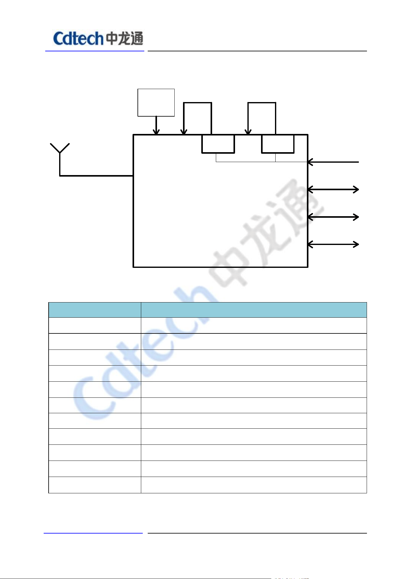
3. Block Diagram
AIC8800DC
0.9V
WL/BT_RF I/O port (shared)
PCM
DC/DC
1.3V
Crystal
GPIO
USB2.0
26MHz
2.4GHz ISM
LDO
+3.3V
4. General Specification
Model
CDW-B1800DL-11H
Product Name
WIFI module
Major Chipset
AIC8800DL
Standard
802.11b/g/n/ax
Modulation Method
BPSK/ QPSK/ 16-QAM/ 64-QAM/256-QAM/1024-QAM
Frequency Band
2.4GHz
WiFi Interface
USB2.0
BLE
Interface
USB2.0
Operating Temperature
-20° C ~ 70° C
Storage Temperature
-20° C ~ 85°C
Humidity
5% to 90% maximum
Moisture Sensitivity Level
MSL3
AIC8800DL
深圳市中龙通电子科技有限公司 Page
4
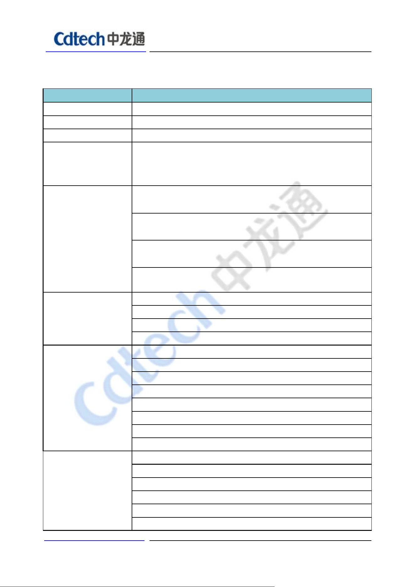
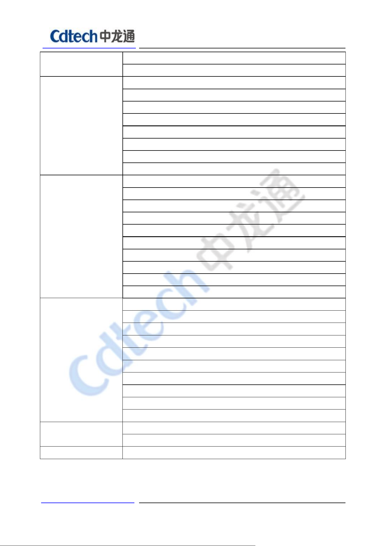
5. RF Specification
A. WiFi RF Specification
Feature
Description
WLAN Standard
IEEE 802.11b/g/n/ax WiFi compliant
Frequency Range
2.400 GHz ~ 2.497 GHz (2.4 GHz ISM Band)
Number of Channels
2.4GHz:Ch1 ~ Ch14
Modulation
802.11b : DQPSK, DBPSK, CCK
802.11 g/n : OFDM /64-QAM,16-QAM, QPSK, BPSK
802.11 ax : OFDM /256-QAM, 64-QAM, 16-QAM, QPSK, BPSK
Receive
Sensitivity
(11b,20MHz)
@8% PER
- 1Mbps PER @ -97dBm, typical
- 2Mbps PER @ -95dBm, typical
- 5.5Mbps PER @ -92dBm, typical
- 11Mbps PER @ -89dBm, typical
Receive
Sensitivity
(11g,20MHz)
@10% PER
- 6Mbps PER @ -91dBm, typical
- 9Mbps PER @ -89dBm, typical
- 12Mbps PER @ -86dBm, typical
- 18Mbps PER @ -83dBm, typical
- 24Mbps PER @ -80dBm, typical
- 36Mbps PER @ -77dBm, typical
- 48Mbps PER @ -74dBm, typical
- 54Mbps PER @ -72dBm, typical
Receive
Sensitivity
(11n,20MHz)
@10% PER
- MCS=0 PER @ -90dBm, typical
- MCS=1 PER @ -87dBm, typical
- MCS=2 PER @ -84dBm, typical
- MCS=3 PER @ -81dBm, typical
- MCS=4 PER @ -78dBm, typical
- MCS=5 PER @ -75dBm, typical
深圳市中龙通电子科技有限公司 Page
5
- MCS=6 PER @ -72dBm, typical
- MCS=7 PER @ -70dBm, typical
Receive
Sensitivity
(11n,40MHz)
@10% PER
- MCS=0 PER @ -87dBm, typical
- MCS=1 PER @ -84dBm, typical
- MCS=2 PER @ -81dBm, typical
- MCS=3 PER @ -78dBm, typical
- MCS=4 PER @ -75dBm, typical
- MCS=5 PER @ -72dBm, typical
- MCS=6 PER @ -69dBm, typical
- MCS=7 PER @ -67dBm, typical
Receive
Sensitivity
(11ax,20MHz)
@10% PER
- HE=0 PER @ -90dBm, typical
- HE=1 PER @ -88dBm, typical
- HE=2 PER @ -86dBm, typical
- HE=3 PER @ -84dBm, typical
- HE=4 PER @ -81dBm, typical
- HE=5 PER @ -79dBm, typical
- HE=6 PER @ -76dBm, typical
- HE=7 PER @ -73dBm, typical
- HE=8 PER @ -70dBm, typical
- HE=9 PER @ -68dBm, typical
Receive
Sensitivity
(11ax,40MHz)
@10% PER
- HE=0 PER @ -88dBm, typical
- HE=1 PER @ -86dBm, typical
- HE=2 PER @ -83dBm, typical
- HE=3 PER @ -80dBm, typical
- HE=4 PER @ -77dBm, typical
- HE=5 PER @ -74dBm, typical
- HE=6 PER @ -72dBm, typical
- HE=7 PER @ -69dBm, typical
- HE=8 PER @ -66dBm, typical
- HE=9 PER @ -64dBm, typical
Maximum Input
Level
802.11b : -10dBm
802.11g/n/ax : -20dBm

深圳市中龙通电子科技有限公司 Page
6
B. Bluetooth Specification
Feature
Description
General Specification
Bluetooth Standard
BLE5.2
Host Interface
USB
Antenna Reference
Small antennas with 0~2 dBi peak gain
Frequency Band
2402 MHz ~ 2480 MHz
Number of Channels
BLE:40 channels
RF Specification
Sensitivity, tolerance
±
2dBm
Sensitivity @ BLE=30.8%
for LE(1Mbps)
-90 dBm
Sensitivity @ BLE=30.8%
for LE(2Mbps)
-91 dBm
Maximum Input Level
GFSK(1Mbps): -20 dBm
π/4-DQPSK(2Mbps): -20 dBm
6. Recommended Operating Rating
symbol
Parameter
Minimum
Typical
Maximum
Units
VDD
3.3V supply voltage
3.0
3.3
3.6
V
VDDIO
I/O supply voltage
1.7
1.8
1.9
V
Current
3.3V rating current
--
--
800
mA
深圳市中龙通电子科技有限公司 Page
7
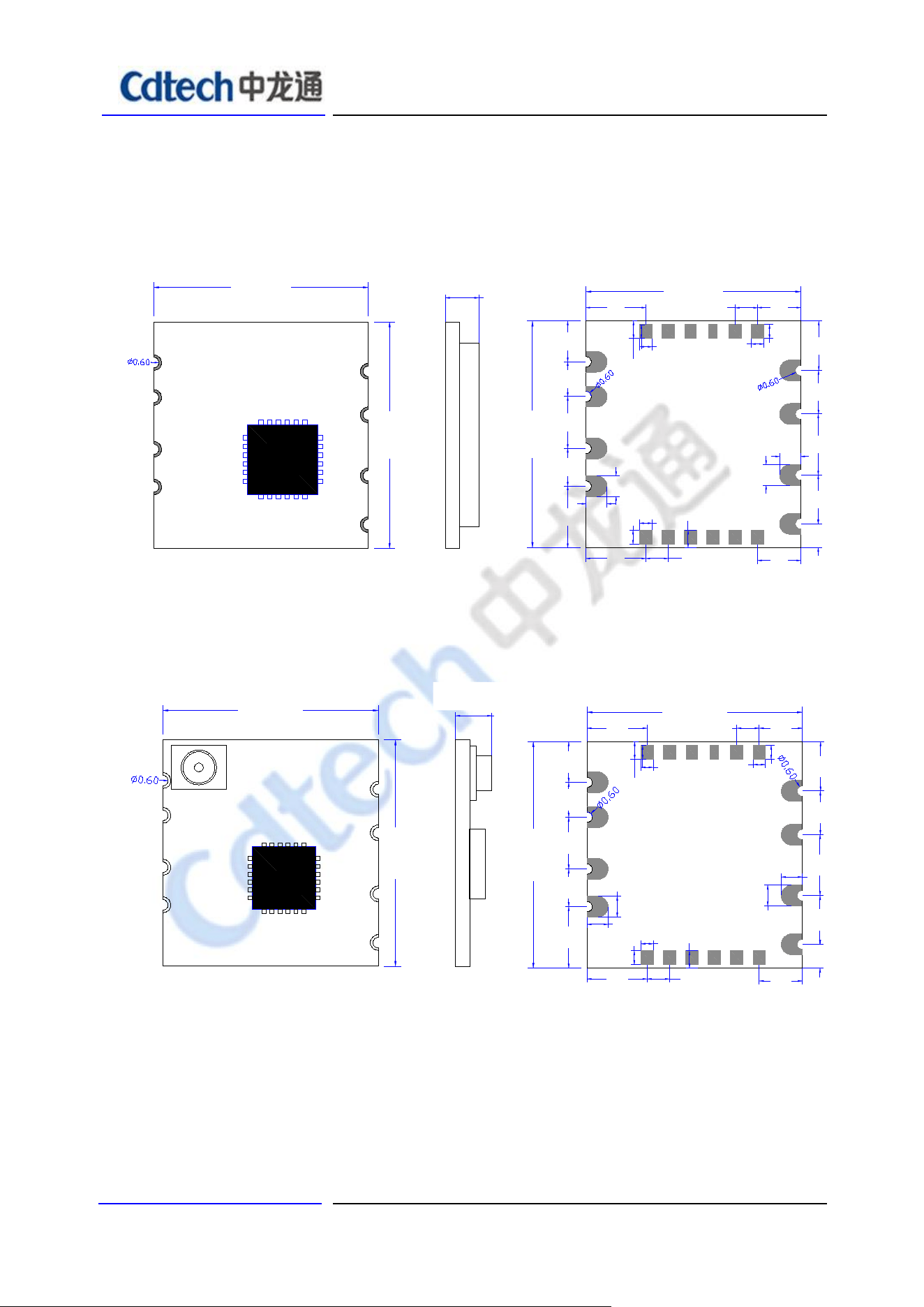
7. Footprint Dimension
7.1 No IPEX Footprint Dimension
12.2±0.2
13±0.2
1
4
11
14
1.90±0.2
12.2±0.2
13
±0.2
3
2
1
4
5 6 7 8 9 10
11
12
13
14
1516
17
181920
0.80
2.453.40
0.70
5*1.27
2.332.002.982.163.53
3.40 5*1.27
2.45
0.70
0.80
0.70
1.37 2.80 3.50
2.50
2.83
1.20
1.20
1.20
1.20
1.00
0.80
1.00
TOP VIEW TOP VIEWSIDE VIEW
7.2 IPEX Footprint Dimension
12.2±0.2
1
4
11
14
Unit:mm
13
±0.2
12.2±0.2
13
±0.2
3
2
1
4
5 6 7 8 9 10
11
12
13
14
1516
17
181920
0.80
2.453.40
0.70
2.332.002.982.163.53
3.40 5*1.27
2.45
0.70
0.80
0.70
1.37 2.80 3.50
2.50
2.83
1.20
1.20
1.20
1.20
1.00
0.80
1.00
5*1.27
TOP VIEW TOP VIEWSIDE VIEW
1.8±0.2
2.25±0.2
深圳市中龙通电子科技有限公司 Page
8
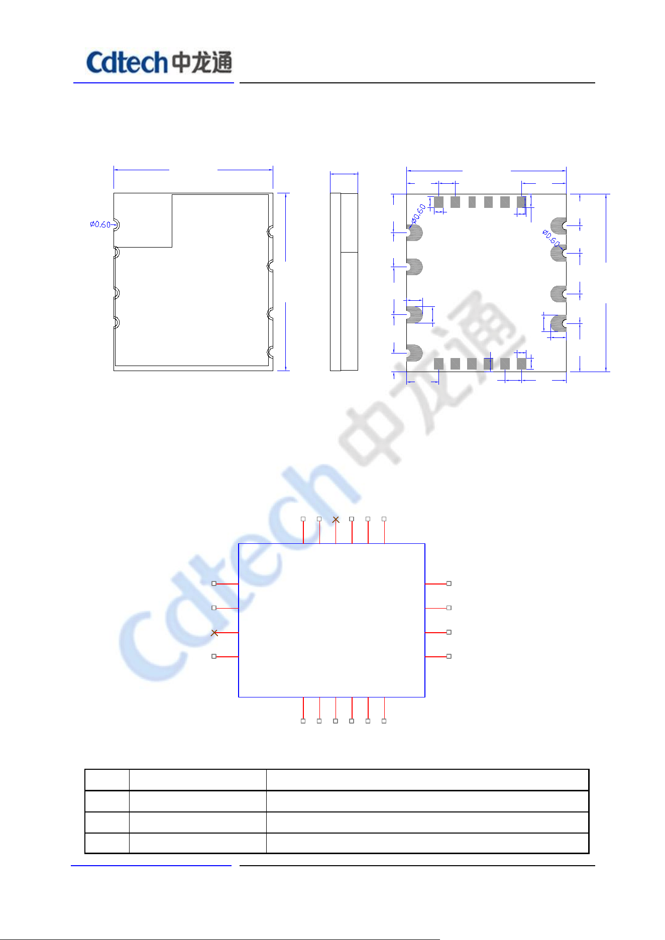
7.3 No IPEX have shielding footprint Dimension
12.2±0.2
1
4
11
14
Unit:mm
13
±0.2
TOP VIEW SIDE VIEW
12.2±0.2
13
±0.2
3
2
1
4
5678910
11
12
13
14
15 16
17
18 19 20
0.80
2.45 3.40
0.70
2.332.002.982.163.53
3.405*1.27
2.45
0.70
0.80
0.70
1.37 2.80 3.50
2.50
2.83
1.20
1.20
1.20
1.20
1.00
0.80
1.00
5*1.27
BOT VIEW
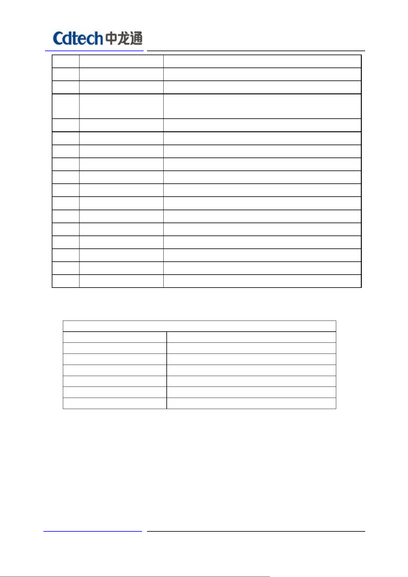
8. Pin Description
RF_1
3
GND
4
RF_0
2
GND
1
GND
14
USB_DP
13
USB_DM
12
VIN
11
PCM_IN
5
PCM_OUT
6
PCM_SYN
7
PCM_CLK
8
BT_WAKE_HST
9
HST_WAKE_BT
10
RXD0
15
TXD0
16
NC
17
CHIP_EN
18
HST_WAKE_WL
19
WL_WAKE_HST
20
NO
Name
Description
1
GND
Ground connections
2
RF0
RF0 I/O port ;When have IPEX the PIN is NC
3
RF1
NC,Keep Floating
2.4±0.2
深圳市中龙通电子科技有限公司 Page
9
4
GND
Ground connections(Note: The PIN must be connected to GND)
5
PCM_IN
BLE_PCM data Input . This pin is also shared with GPIOA2.
6
PCM_OUT
BLE_PCM data Output .
This pin is also shared with GPIOA3
7
PCM_SYNC
BLE_
PCM frame Synchronization. This pin is also shared
with GPIOA0.
8
PCM_CLK
BLE_
PCM Clock. This pin is also shared with GPIOA1.
9
BT_WAKE_HOST
BLE
Wakeup Host pin. This pin is also Shared with GPIOB2.
10
HOST_WAKE_BT
Host Wakeup
BLE
pin. This pin is also shared with GPIOB3.
11
VCC
Power supply 3.3V is required
12
USB_DM
High-Speed USB D- Signal
13
USB_DP
High-Speed USB D+ Signal
14
GND
Ground connections
15
RXD0
Floating, Debug pin
16
TXD0
Floating, Debug pin
17
NC
Floating
18
Chip_en
Low closed.
19
HOST_WAKE_WLAN
Host Wakeup WLAN pin. This pin is also shared with GPIOB0.
20
WLAN_WAKE_HOST
WLAN Wakeup Host pin. This pin is also Shared with GPIOB1.
9. Supplier
Supplier list
Name of material
Material brand
Crystal
JWT/FK/TKD/Murata/TXC
Inductor
Sunlord/ CHILISIN/ SAMWHA/DDY
Wifi chip
AIC
Capacitance
SAMSUNG /EYANG/Murata
Resistance
UniOhm /YAGEO
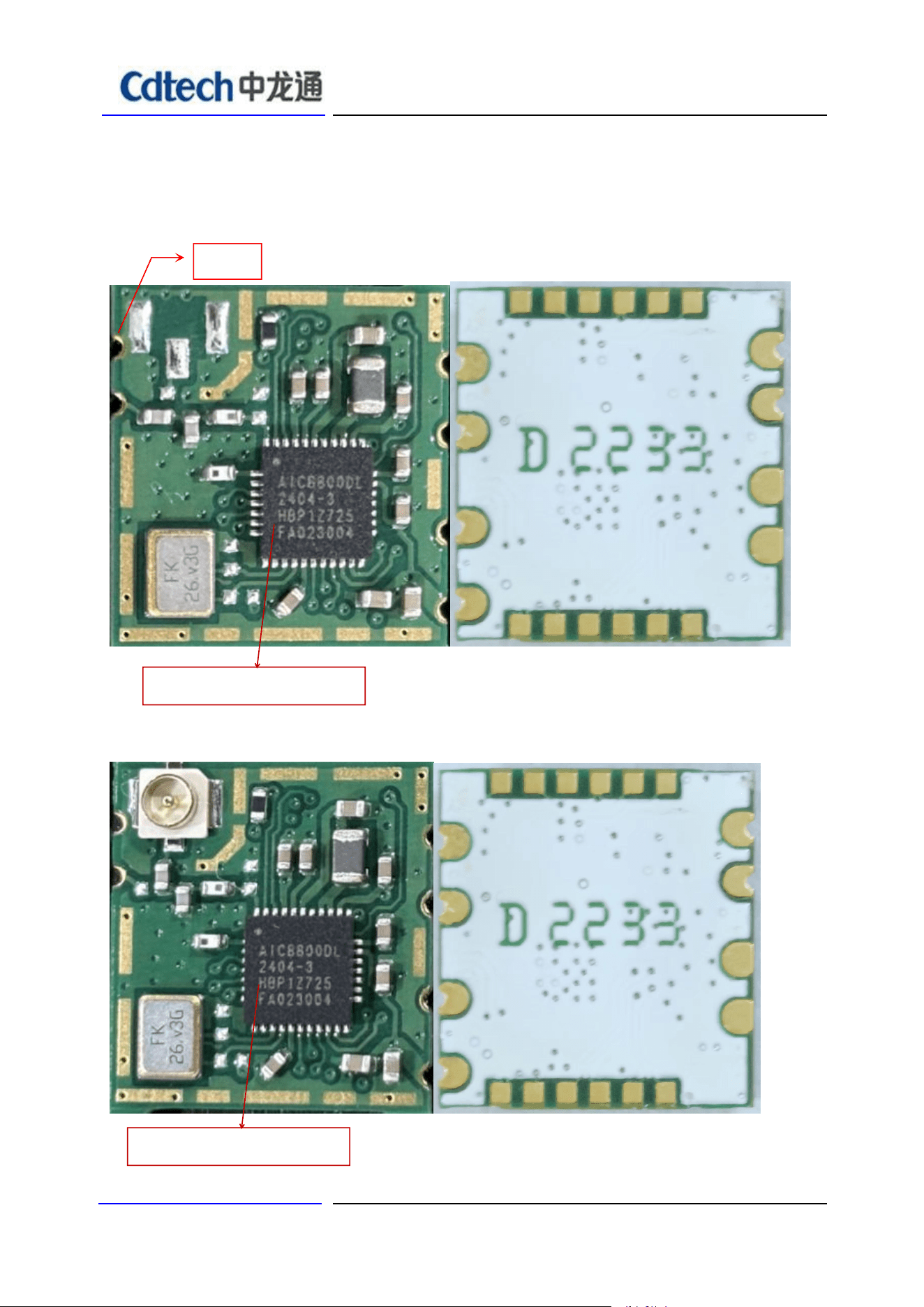
PCB(12.2x13x0.8mm)
A,O,I,F
深圳市中龙通电子科技有限公司 Page
12
11. Layout Recommendation
1.0
0.8
0.7 1.27 2.451.273.40
1.20
1.00
1.20
1.37
2.80
3.50
2.50
2.83
0.7
2.451.273.40
1.20
1.201.00
3.53
2.16
2.98
2.00
2.33
13mm
12.2mm
20
19
18
17
16
15
14
13
12
11
10
9
8
7
6
5
4
3
2
1
1.0
0.8
(Top view)
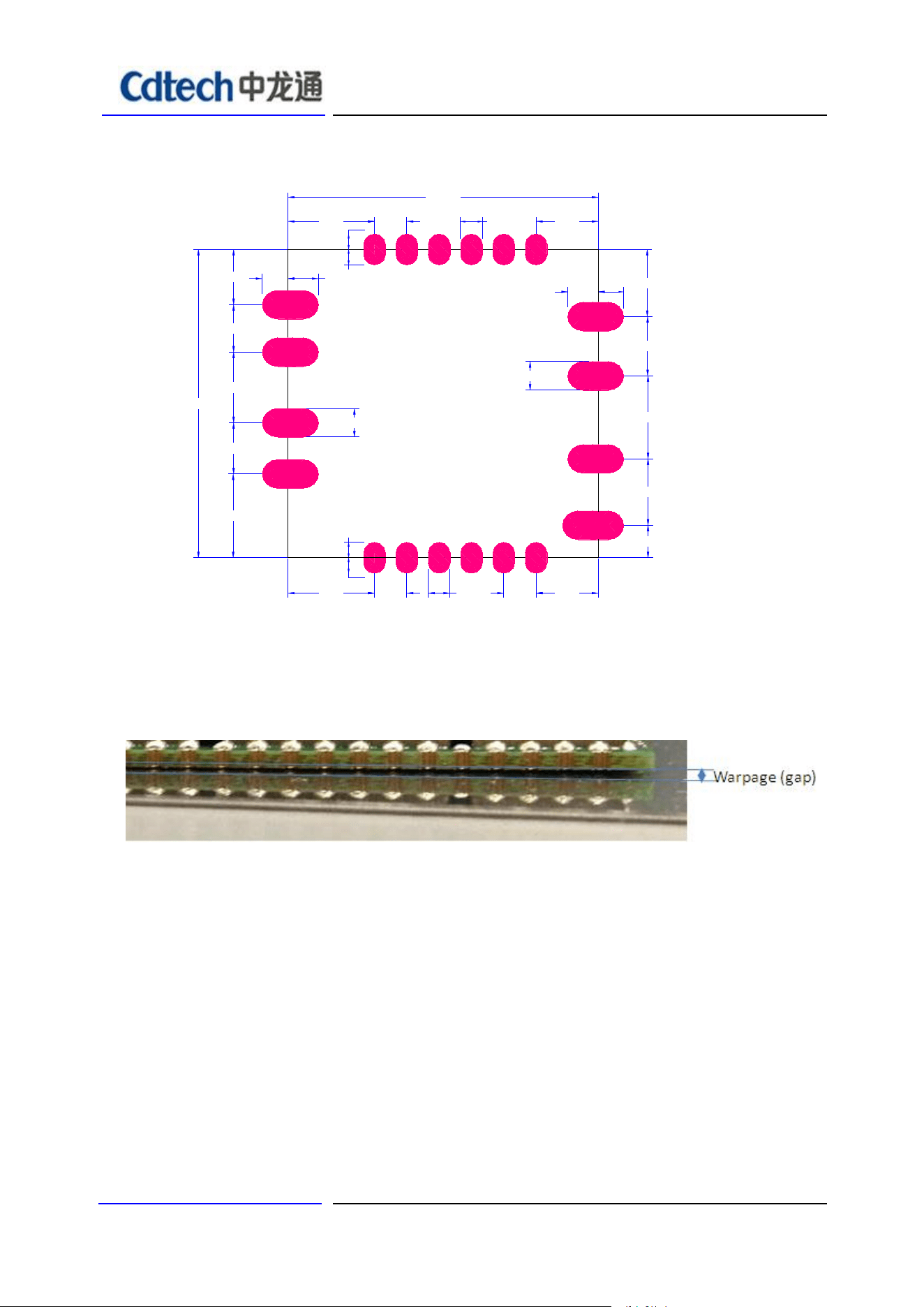
12. Warpage
13. Baking & storage temperature & Recommended Reflow Profile
13.1 Baking & storage temperature
A. Storage life:12 months. Storage conditions:<40℃. Relative humidity:<90%R.H.

深圳市中龙通电子科技有限公司 Page
13
B. After this bag is opened , devices that will be subjected to infrared reflow, vapor-phase reflow, or
equivalent processing must be .(模块包装被拆后,SMT 组装之时限)
a. Check the humidity card :stored at ≦20%RH.If :30%~40%(pink)or greater than 40%(red).Labeling
module has moisture absorption.( 检查湿度卡:显示值应小于30%(蓝色),如:30%~40%(粉红色)
或 者大于40%(红色)表示模块已吸湿气.)
b. Mounted within 168 hours at factory conditions of: t≦30%℃,≦60%R.H.
(工厂环境温度湿度管制:≦30%℃,≦60%R.H, 168小时内。)
c. Once opened, the workshop the preservation of life for168 hours.
(拆封后,车间的保存寿命为168小时.)
C. Module apart packing after 168 hours,If baking is required, devices may be baked for.
(如在拆封后的168个小时内未使用完,需要烘烤,烘烤条件如下:)
a. Modules must be to remove module moisture problem. (模块须重新烘烤,以除去模块吸湿问题.)
b. Baking temperature: 40℃±5℃, 120 hours. (烘烤温度条件:40℃±5℃,120小时).
c. After baking, put proper amount of desiccant to seal packages.
(烘烤后,放入适量的干燥剂再密封包装)
深圳市中龙通电子科技有限公司 Page
14
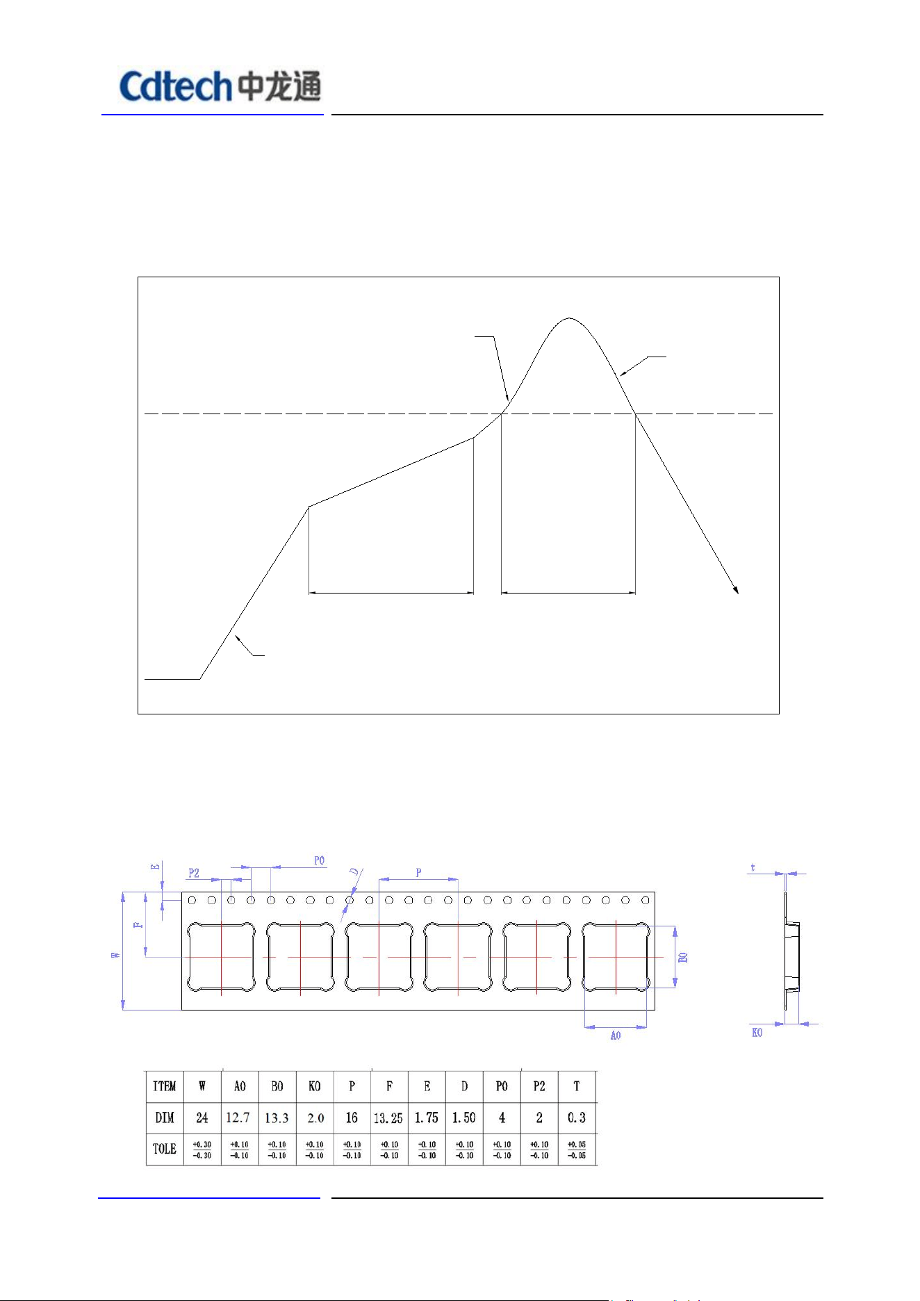
13.2 Recommended Reflow Profile
Referred IPC/JEDEC standard.
Peak Temperature : <250°C
Number of Times : ≤2 times
217℃
60~120 sec
25℃
40~60 sec
Ramp up rate:
Max. 2℃/sec
Prehe at: 150~200℃
Slope: 1~2℃/sec max.
(217℃ to peak)
peak: 245
+0
-5
℃
Ramp down rate:
Max. 2.5℃/sec
Time(sec)
14. Packing information
14.1 Carrier size Detail:
深圳市中龙通电子科技有限公司 Page
15
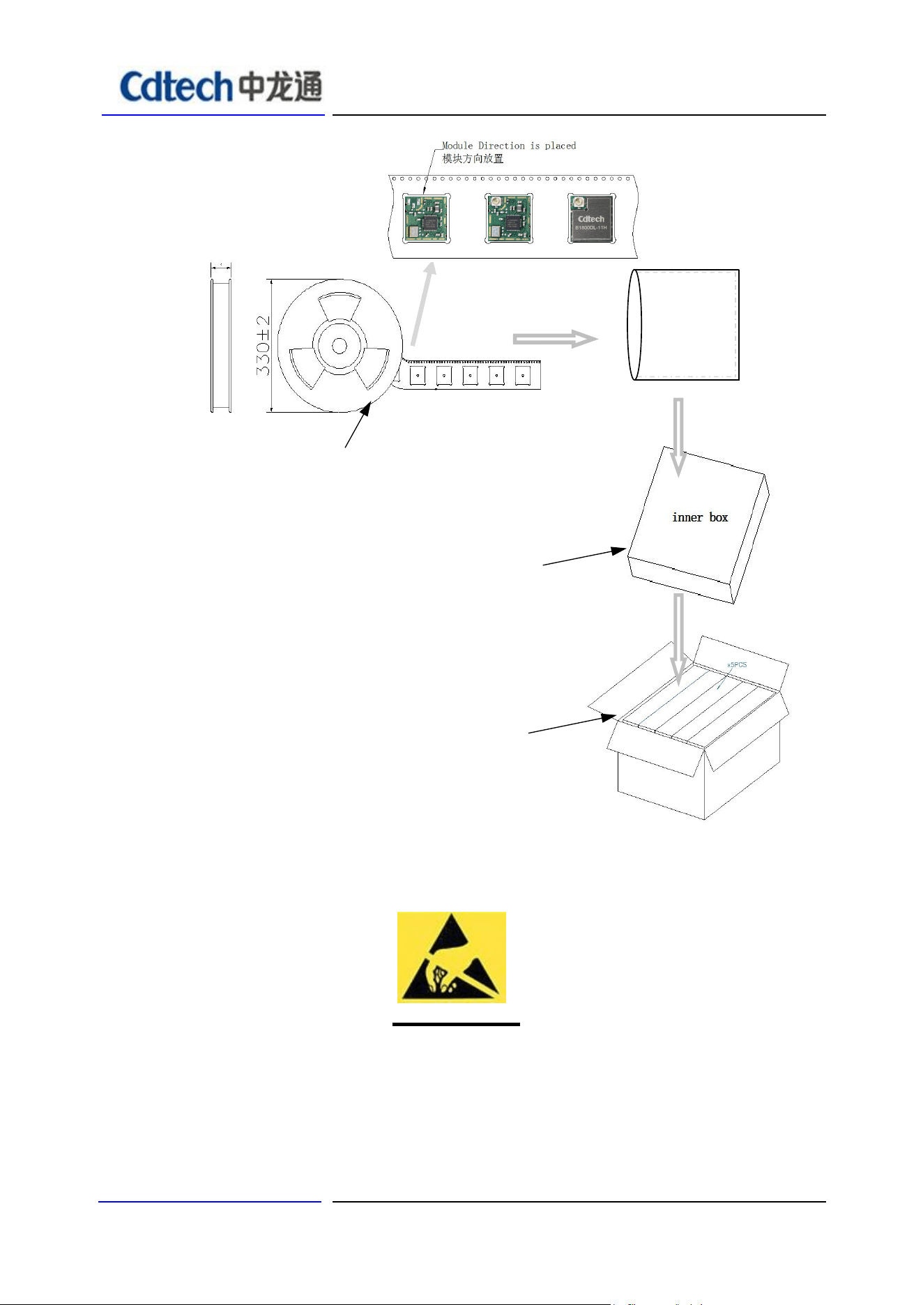
14.2 Packaging Detail:
ESD
CAUTION
The B1800DL series module is ESD (electrostatic discharge) sensitive device and may be
damaged with ESD or spike voltage. Although B1800DL series module is with built-in ESD
protection circuitry, please handle with care to avoid the permanent malfunction or the
performance degradation.
inner box K3K:
33.5cm*34.7cm*7cm
A box of 2000 PCS
carton K=A:
36.4*35.7*37.5cm
A case of 10000 PCS
Color of plastic disc: blue
A roll of 2000pcs(前后留空20pcs)
24±2mm
Vacuum
packing
AL BAG ANTI-STATIC

FCC WARNING
FCC Caution: Any changes or modifications not expressly approved by the party responsible
for compliance could void the user's authority to operate this equipment.
This device complies with Part 15 of the FCC Rules. Operation is subject to the following two
conditions:
(1) This device may not cause harmful interference, and (2) this device must accept any
interference received, including interference that may cause undesired operation.
This device and its antenna(s) must not be co-located or operating in conjunction
with any other antenna or transmitter.
15.105 Information to the user.
(b) For a Class B digital device or peripheral, the instructions furnished the
user shall include the following or similar statement, placed in a prominent
location in the text of the manual:
Note: This equipment has been tested and found to comply with the limits for a Class B digital
device, pursuant to part 15 of the FCC Rules.
These limits are designed to provide reasonable protection against harmful interference in a
residential installation. This equipment generates, uses and can radiate radio frequency energy
and, if not installed and used in accordance with the instructions, may cause harmful
interference to radio communications. However, there is no guarantee that interference will not
occur in a particular installation. If this equipment does cause harmful interference to radio or
television reception, which can be determined by turning the equipment off and on, the user is
encouraged to try to correct the interference by one or more of the following measures:
—Reorient or relocate the receiving antenna.
—Increase the separation between the equipment and receiver.
—Connect the equipment into an outlet on a circuit different from that to which
the receiver is connected.
—Consult the dealer or an experienced radio/TV technician for help.
This equipment complies with FCC radiation exposure limits set forth for an uncontrolled
environment. This equipment should be installed and operated with minimum distance 20 cm
between the radiator and your body.
Radiation Exposure Statement:
This equipment complies with FCC radiation exposure limits set forth for an
uncontrolled environment.
This transmitter must not be co-located or operating in conjunction with any other
antenna or transmitter.
The availability of some specific channels and/or operational frequency bands
are country dependent and are firmware programmed at the factory to match
the intended destination.
The firmware setting is not accessible by the end user.
The final end product must be labelled in a visible area with the following:
“Contains Transmitter Module FCC ID: 2A4AS-2606E”

Requirement per KDB996369 D03
2.2 List of applicable FCC rules
List the FCC rules that are applicable to the modular transmitter. These are the rules
that specifically establish the bands of operation, the power, spurious emissions, and
operating fundamental frequencies. DO NOT list compliance to unintentional-radiator
rules (Part 15 Subpart B) since that is not a condition of a module grant that is
extended to a host manufacturer. See also Section 2.10 below concerning the need
to notify host manufacturers that further testing is required.3
Explanation: This module meets the requirements of FCC part 15C(15.247).
2.3 Summarize the specific operational use conditions
Describe use conditions that are applicable to the modular transmitter, including for
example any limits on antennas, etc. For example, if point-to-point antennas are used
that require reduction in power or compensation for cable loss, then this information
must be in the instructions. If the use condition limitations extend to professional
users, then instructions must state that this information also extends to the host
manufacturer’s instruction manual. In addition, certain information may also be
needed, such as peak gain per frequency band and minimum gain.
Explanation: The EUT only have one FPC antenna, Yes, the module contains a permanently
attached antenna, The antenna gain is BLE/WIFI 2.4G:4.18dBi, The use condition of the
prototype is mobile.
2.4 Limited module procedures
If a modular transmitter is approved as a “limited module,” then the module
manufacturer isresponsible for approving the host environment that the limited
module is used with. The manufacturer of a limited module must describe, both in the
filing and in the installation instructions, the alternative means that the limited module
manufacturer uses to verify that the host meets the necessary requirements to satisfy
the module limiting conditions.
A limited module manufacturer has the flexibility to define its alternative method to
address the conditions that limit the initial approval, such as: shielding, minimum
signaling amplitude, buffered modulation/data inputs, or power supply regulation. The
alternative method could include that the limited module manufacturer reviews
detailed test data or host designs prior to giving the host manufacturer approval.
This limited module procedure is also applicable for RF exposure evaluation when it
is necessary to demonstrate compliance in a specific host. The module manufacturer
must state how control of the product into which the modular transmitter will be
installed will be maintained such that full compliance of the product is always
ensured. For additional hosts other than the specific host originally granted with a
limited

module, a Class II permissive change is required on the module grant to register the
additional host as a specific host also approved with the module.
Explanation: The module is a single module.
2.5 Trace antenna designs
For a modular transmitter with trace antenna designs, see the guidance in Question
11 of KDB Publication 996369 D02 FAQ – Modules for Micro-Strip Antennas and
traces. The integration information shall include for the TCB review the integration
instructions for the following aspects: layout of trace design, parts list (BOM),
antenna, connectors, and isolation requirements.
a) Information that includes permitted variances (e.g., trace boundary limits,
thickness, length, width, shape(s), dielectric constant, and impedance as applicable
for each type of antenna);
b) Each design shall be considered a different type (e.g., antenna length in
multiple(s) of frequency, the wavelength, and antenna shape (traces in phase) can
affect antenna gain and must be considered);
c) The parameters shall be provided in a manner permitting host manufacturers to
design the printed circuit (PC) board layout;
d) Appropriate parts by manufacturer and specifications;
e) Test procedures for design verification; and
f) Production test procedures for ensuring compliance.
The module grantee shall provide a notice that any deviation(s) from the defined
parameters of the antenna trace, as described by the instructions, require that the
host product manufacturer must notify the module grantee that they wish to change
the antenna trace design. In this case, a Class II permissive change application is
required to be filed by the grantee, or the host manufacturer can take responsibility
through the change in FCC ID (new application) procedure followed by a Class II
permissive change application.
Explanation: No, The module has no tracking antenna design, is FPC antenna.
2.6 RF exposure considerations
It is essential for module grantees to clearly and explicitly state the RF exposure
conditions that permit a host product manufacturer to use the module. Two types of
instructions are required for RF exposure information: (1) to the host product
manufacturer, to define the application conditions (mobile, portable – xx cm from a
person’s body); and (2) additional text needed for the host product manufacturer to
provide to end users in their end-product manuals. If RF exposure statements and
use conditions are not provided, then the host product manufacturer is required to
take responsibility of the module through a change in FCC ID (new application).
Explanation: This module complies with FCC RF radiation exposure limits set forth
for an uncontrolled environment, This equipment should be installed and operated
with a minimum distance of 20 centimeters between the radiator and your body." This

module is designed to comply with the FCC statement,
FCC ID: 2A4AS-2606E
2.7 Antennas
A list of antennas included in the application for certification must be provided in the
instructions. For modular transmitters approved as limited modules, all applicable
professional installer instructions must be included as part of the information to the
host product manufacturer. The antenna list shall also identify the antenna types
(monopole, PIFA, dipole, etc. (note that for example an “omni-directional antenna” is
not considered to be a specific “antenna type”)).
For situations where the host product manufacturer is responsible for an external
connector, for example with an RF pin and antenna trace design, the integration
instructions shall inform the installer that unique antenna connector must be used on
the Part 15 authorized transmitters used in the host product. The module
manufacturers shall provide a list of acceptable unique connectors.
Explanation: The EUT only have one FPC antenna, Yes, the module contains a
permanently attached antenna, The antenna gain is BLE/WIFI 2.4G:4.18dBi.
2.8 Label and compliance information
Grantees are responsible for the continued compliance of their modules to the FCC
rules. This
includes advising host product manufacturers that they need to provide a physical or
e-label stating “Contains FCC ID” with their finished product. See Guidelines for
Labeling and User Information for RF Devices – KDB Publication 784748.
Explanation:The host system using this module, should have label in a visible area indicated
the following texts: "Contains FCC ID: 2A4AS-2606E.
2.9 Information on test modes and additional testing requirements5
Additional guidance for testing host products is given in KDB Publication 996369 D04
Module Integration Guide. Test modes should take into consideration different
operational conditions for a stand-alone modular transmitter in a host, as well as for
multiple simultaneously transmitting modules or other transmitters in a host product.
The grantee should provide information on how to configure test modes for host
product evaluation for different operational conditions for a stand-alone modular
transmitter in a host, versus with multiple, simultaneously transmitting modules or
other transmitters in a host.
Grantees can increase the utility of their modular transmitters by providing special
means, modes, or instructions that simulates or characterizes a connection by
enabling a transmitter. This can greatly simplify a host manufacturer’s determination
that a module as installed in a host complies with FCC requirements.
Explanation: WiFiRanger, A CHINA DRAGON TECHNOLOGY LIMITED can increase the
utility of our modular transmitters by providing instructions that simulates or
characterizes a connection by enabling a transmitter.

2.10 Additional testing, Part 15 Subpart B disclaimer
The grantee should include a statement that the modular transmitter is only FCC
authorized for the specific rule parts (i.e., FCC transmitter rules) listed on the grant,
and that the host product manufacturer is responsible for compliance to any other
FCC rules that apply to the host not covered by the modular transmitter grant of
certification. If the grantee markets their product as being Part 15
Subpart B compliant (when it also contains unintentional-radiator digital circuity), then
the grantee shall provide a notice stating that the final host product still requires Part
15 Subpart B compliance testing with the modular transmitter installed.
Explanation: The host shoule be evaluated by the FCC Subpart B.
This product uses FPC antenna with a maximum antenna gain of BLE/WIFI
2.4G:4.18dBi.
2.11 Note EMI Considerations
Note that a host manufacture is recommended to use D04 Module Integration Guide
recommending as "best practice" RF design engineering testing and evaluation in case non-linear
interactions generate additional non-compliant limits due to module placement to host
components or properties
For standalone mode, reference the guidance in D04 Module Integration Guide and for
simultaneous mode7; see D02 Module Q&A Question 12, which permits the host manufacturer
to confirm compliance.
Explanation: The customer is an independent module and has been implemented in
accordance with D04.
2.12 How to make changes
Since . only Grantees are permitted to make permissive changes, it is recommended that module
manufactures provide contact information and some guidance to host providers in the integration
instructions if they expect their module will be used differently than granted.
Explanation: Contact Information: We have provided our technical support contact (email:
chenyx2@reolink.com.cn) for host manufacturers to reach us regarding any proposed changes to
the module's operational conditions or integration method.

IC statement
This device contains licence-exempt transmitter(s)/receiver(s) that comply with Innovation, Science
and Economic DevelopmentCanada’s licence-exempt RSS(s). Operation is subject to the following
two conditions:
(1) This device may not cause interference.
(2) This device must accept any interference, including interference that may cause undesired
operation of the device.
Cet appareil contient un émetteur (S)/ récepteur (S) exempté (S) de licence qui est conforme
Avec l’innovation, la Science
Et les RSS exemptées de permis de développement économique Canada. Le fonctionnement est
Sous réserve de ce qui suit
Deux conditions:
(1) ce dispositif ne peut pas causer d’interférence.
(2) ce dispositif doit accepter toute interférence, y compris l’interférence qui peut
Provoquer un fonctionnement indésirable de l’appareil.
This transmitter must not be co-located or operating in conjunction with any other antenna
ortransmitter. This equipment should be installed and operated with a minimum distance of
20centimeters between the radiator and your body.
Cet émetteur ne doit pas être Co-placé ou ne fonctionnant en même temps qu'aucune autre
antenne ouémetteur. Cet équipementdevrait être installé et actionné avec une distance minimum
de 20 centimètres entre le radiateur et votre corps.
The radio transmitter IC: 28290-2606E has been approved by The Ministry of Innovation,
Science and Economic Development of Canada to use the following antenna types with the
specified maximum allowed gain. Antenna types not included in this list, whose gain is higher
than the maximum gain of any type listed, are strictly prohibited from use with this device.
Cet émetteur radio IC : 28290-2606E a été approuvé par Innovation, Sciences et
Développement économique Canada pour fonctionner avec les types d'antenne énumérés ci-
dessous, avec le gain maximal admissible indiqué. Les types d'antenne non inclus dans cette
liste qui ont un gain supérieur au gain maximum indiqué pour tout type répertorié sont
strictement interdits pour une utilisation avec cet appareil.
Type of antenna:
FPC antenna

Antenna Gain:
2.4G :2400-2500(4.18dBi)
Impedance:
50hm
Manufacture:
SHENZHEN 3GTX ANTENNA TECHNOLOGY CO.,LTD.
Model:
CDW-B1800DL-11H