ESP32-C6 WiFi Module
SKU: ESP32-P4-C6-WiFi
(ESP32-C6 WiFi Add-on Module for 4D Systems ESP32-P4 Display Series)
Datasheet
Revision 1.0
Copyright © 2026 4D Systems
Content may change at any time. Please refer to the resource centre for latest documentation.
Contents
31. Description
52. Features
63. Hardware Overview
84. Hardware Interface - Pins
84.1. Serial Ports - 3.3V TTL
84.2. Communications - SDIO
85. Software Development
96. Mechanical Details
96.1. ESP32-P4-C6-WiFi Module
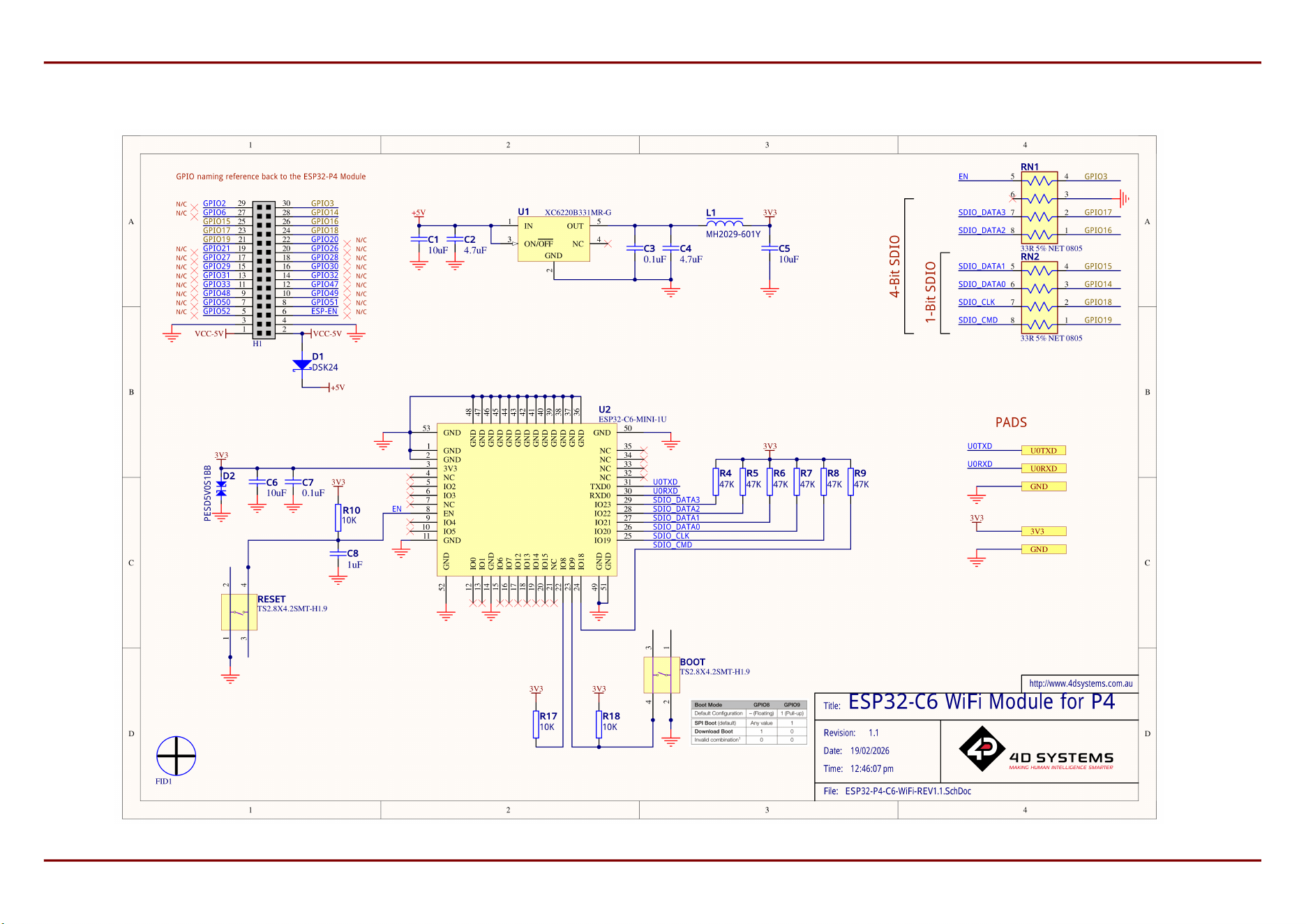
107. Schematic Circuit Details REV 1.1
118. Specications
129. Revision History
1310. Legal Notice
1310.1. Proprietary Information
1310.2. Disclaimer of Warranties & Limitations of Liabilities
4D Systems
DATASHEET
Page 2 of 13

1. Description
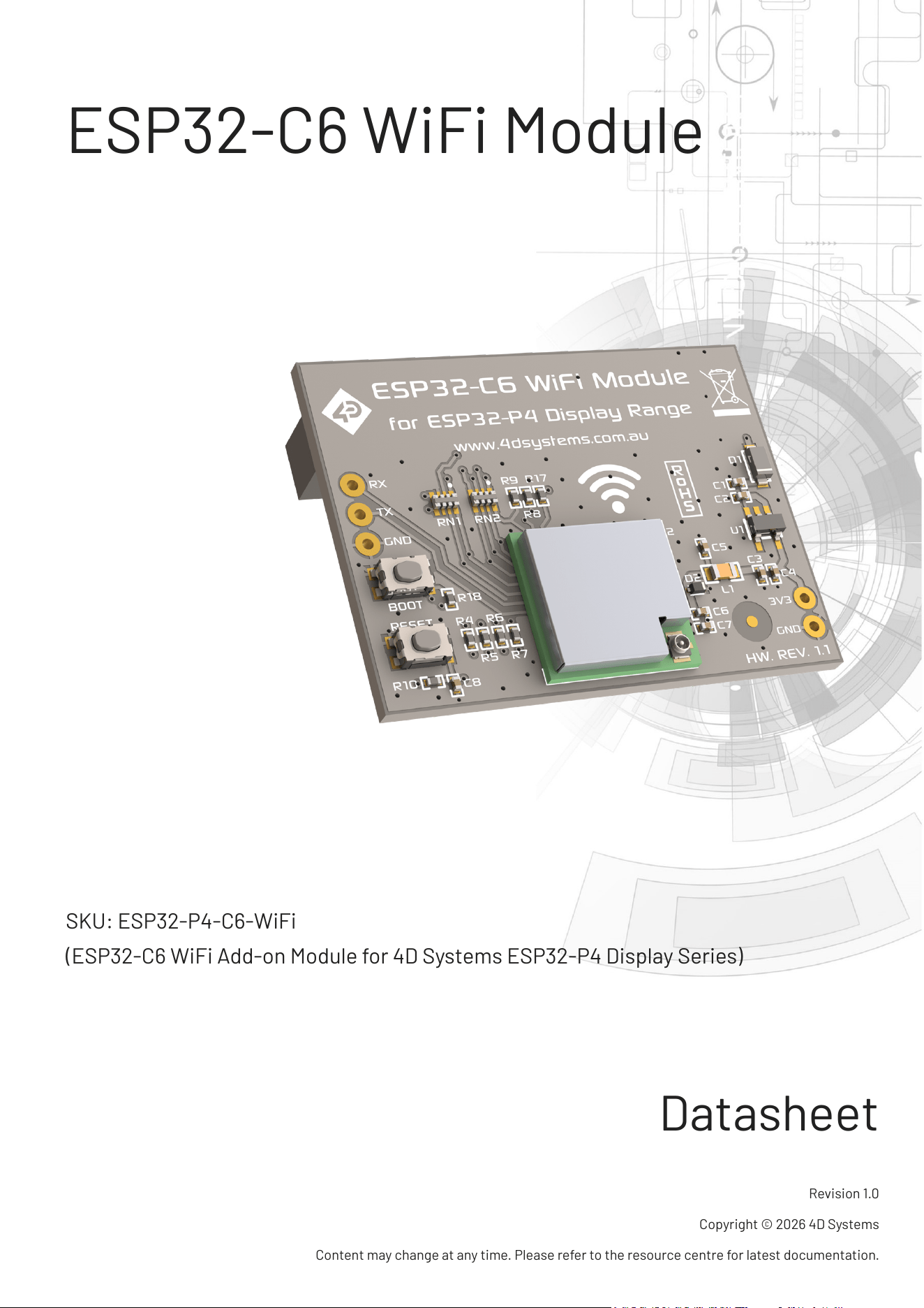
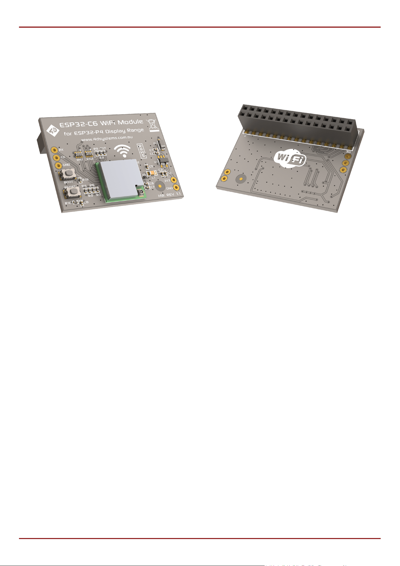
The ESP32-P4-C6-WiFi is an ESP32-C6 WiFi add-on module for the 4D Systems ESP32-P4 display range, and is
designed and manufactured by 4D Systems.
This WiFi add-on module is designed specically to directly plug on the back of the ESP32-P4 and ESP32-P4-
Round series of display modules from 4D Systems, providing WiFi and BT connectivity to the ESP32-P4 SoC.
At the time of writing, this module is directly compatible with the following modules:
ESP32-P4-70
ESP32-P4-70CT-CLB
ESP32-P4-70CT
ESP32-P4-80
ESP32-P4-80CT-CLB
ESP32-P4-80CT
ESP32-P4-90
ESP32-P4-90CT-CLB
ESP32-P4-90CT
ESP32-P4-101
ESP32-P4-101CT-CLB
ESP32-P4-101CT
ESP32-P4-34R-CLB
ESP32-P4-34RCT-CLB
ESP32-P4-40R-CLB
ESP32-P4-40RCT-CLB
This WiFi add-on module features the Espressif ESP32-C6-MINI-1U-N4 canned WiFi module, which features the
Espressif ESP32-C6 SoC. It features 802.11ax-compliant WiFi, and Bluetooth LE 5.3 certied Bluetooth
communications.
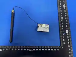
This WiFi add-on module supports only an external antenna, which is simply connected to the w.FL connector on
the ESP32-C6-MINI-1U module directly. A suitable w.FL (IPX-3) to SMA cable and screw on SMA Antenna is supplied
with this module. Alternative IPX-3 cables and antennas are freely available on the market if the supplied one is
not suitable.
•
•
•
•
•
•
•
•
•
•
•
•
•
•
•
•
ESP32-C6 WiFi Module Description
4D Systems
DATASHEET
Page 3 of 13
These WiFi modules can be programmed over the UART, changing the ESP32-C6 application if required. From
factory, these ship with the ESP-Hosted slave application running over SDIO supplied by Espressif, which allow
direct connection with the ESP32-P4 display modules. However if customisation is required, the ESP32-C6 can be
reprograrmmed by the User to suit custom requirements.
ESP32-P4-C6-WiFi Module - Front ESP32-P4-C6-WiFi Module - Rear
ESP32-C6 WiFi Module Description
4D Systems
DATASHEET
Page 4 of 13

2. Features
Powerful ESP32-C6 RISC-V 32-bit single-core microprocessor, inside ESP32-C6-MINI-1U-N4 module
Up to 160Mhz
320KB ROM, 512KB HP SRAM, 16KB LP SRAM, 4MB In-Package Flash
UART programming interface
4bit SDIO Bus to ESP32-P4 display modules
30pin female pin header, for direct connect to ESP32-P4 display modules, supplying Power and SDIO Comms
Bus etc
4.0V to 6.0V range operation (single supply), 5V recommended.
w.FL (IPX-3) Antenna interface
w.FL (IPX-3) to SMA cable + SMA Antenna, supplied
RoHS and REACH compliant.
CE/EMC and UKCA compliance pending.
PCB is UL 94V-0 Flammability Rated.
Module dimensions:
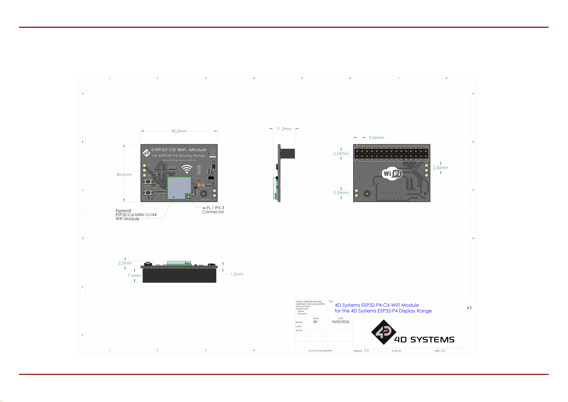
40.0mm x 30.0mm x 11.2mm
Weighing (approximately):
6 g (excluding external antenna)
•
•
•
•
•
•
•
•
•
•
•
•
•
•
•
•
ESP32-C6 WiFi Module Features
4D Systems
DATASHEET
Page 5 of 13
3. Hardware Overview
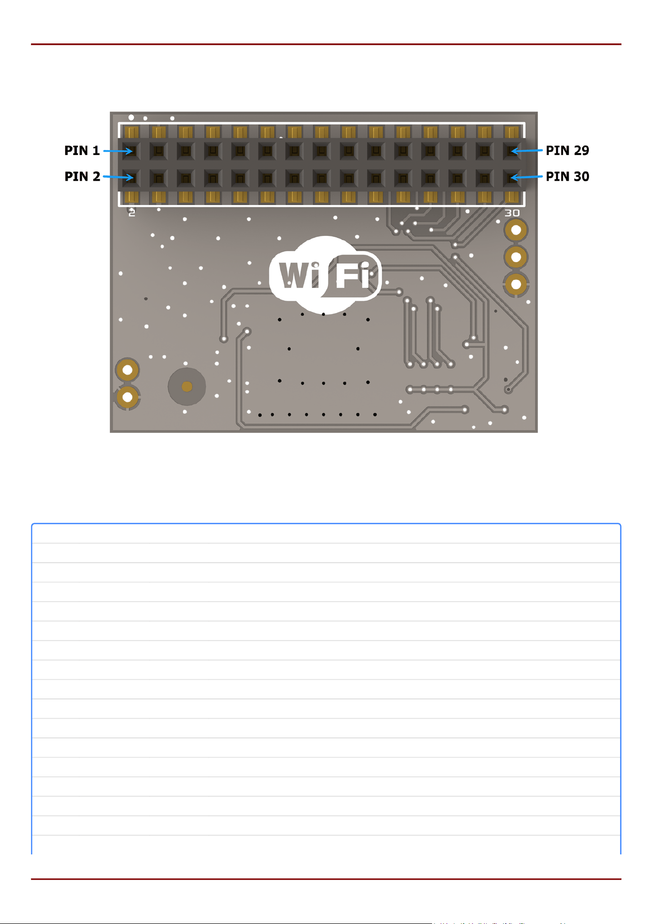
Pinout of 30-way Female connector (Rear view)
30-pin Interface Pinout
Pin Symbol I/O Description
1 5V IN P Voltage Supply +ve input pin. The range is 4.0V to 6.0V, nominal 5.0V.
2 5V IN P Voltage Supply +ve input pin. The range is 4.0V to 6.0V, nominal 5.0V.
3 GND P Supply Ground
4 GND P Supply Ground
5 N/C - Not Connected / Unused
6 N/C - Not Connected / Unused
7 N/C - Not Connected / Unused
8 N/C - Not Connected / Unused
9 N/C - Not Connected / Unused
10 N/C - Not Connected / Unused
11 N/C - Not Connected / Unused
12 N/C - Not Connected / Unused
13 N/C - Not Connected / Unused
14 N/C - Not Connected / Unused
15 N/C - Not Connected / Unused
16 N/C - Not Connected / Unused
ESP32-C6 WiFi Module Hardware Overview
4D Systems
DATASHEET
Page 6 of 13
Pin Symbol I/O Description
17 N/C - Not Connected / Unused
18 N/C - Not Connected / Unused
19 N/C - Not Connected / Unused
20 N/C - Not Connected / Unused
21 SDIO_CMD I/O SDIO Bus CMD line - Bidirectional
22 N/C - Not Connected / Unused
23 SDIO_DATA3 I/O SDIO Bus DATA 3 line - Bidirectional
24 SDIO_CLK I SDIO Bus Clock line
25 SDIO_DATA1 I/O SDIO Bus DATA 1 line - Bidirectional
26 SDIO_DATA2 I/O SDIO Bus DATA 2 line - Bidirectional
27 N/C - Not Connected / Unused
28 SDIO_DATA0 I/O SDIO Bus DATA 0 line - Bidirectional
29 N/C - Not Connected / Unused
30 EN I/O Reset of the ESP32-C6 from ESP32-P4 - Also connected to the RESET Button
I = Input, O = Output, P = Power
Please refer to the Espressif ESP32-C4-MINI-1U datasheet for specic detail on the capability of the ESP32-C6, in
conjunction with the schematic of this module.
Note
1.
2.
ESP32-C6 WiFi Module Hardware Overview
4D Systems
DATASHEET
Page 7 of 13

4. Hardware Interface - Pins
This section describes in detail the hardware interface pins of the module.
4.1. Serial Ports - 3.3V TTL
This WiFi add-on module has a single UART, which is connected only to the solderable TH pads on the module, and
is used primarily for the reprogramming of the ESP32-C6 rmware by the end user. This is UART0, and is where
the boot and debug messages are sent by default, and is useful when diagnosing issues or troubleshooting your
code (if using custom rmware).
Please refer to the Espressif ESP32-C6-MINI-1U Datasheet for more details.
The module can be programmed over UART utilising the RX/TX pads, in conjunction with the BOOT and RESET
buttons. It is recommended to unplug the module from the ESP32-P4 display, and power the module via the 3V3
and GND pins, or via the 5V and GND pins on the 30-way female connector.
For most applications, reprogramming of this module is not required.
4.2. Communications - SDIO
This WiFi add-on module has a dedicated 4-bit SDIO bus, which is the bus used to communicate between the
ESP32-C6 and the ESP32-P4 display module. This bus is the highest speed available for the ESP32-C6, and
enables high-speed communications to the ESP32-P4, allowing things like streaming Audio and steaming Video to
be possible in conjunction with a 4D Systems ESP32-P4 display module.
5. Software Development
While it's recommended to use the default ESP-Hosted slave application which comes preloaded to use it with
ESP32-P4 display applications, it is possible to develop custom rmware for this board to either update or change
entirely the SDIO-based communication between the two microprocessors. It is up to the user to match both the
ESP32-P4 and ESP32-C6 custom communication.
Several options are made available to users from Espressif, including:
Arduino IDE using Arduino-ESP32 core
ESP-IDF
Please refer to the ESP-Hosted documentation for detailed information on the default rmware.
•
•
ESP32-C6 WiFi Module Hardware Interface - Pins
4D Systems
DATASHEET
Page 8 of 13
8. Specifications
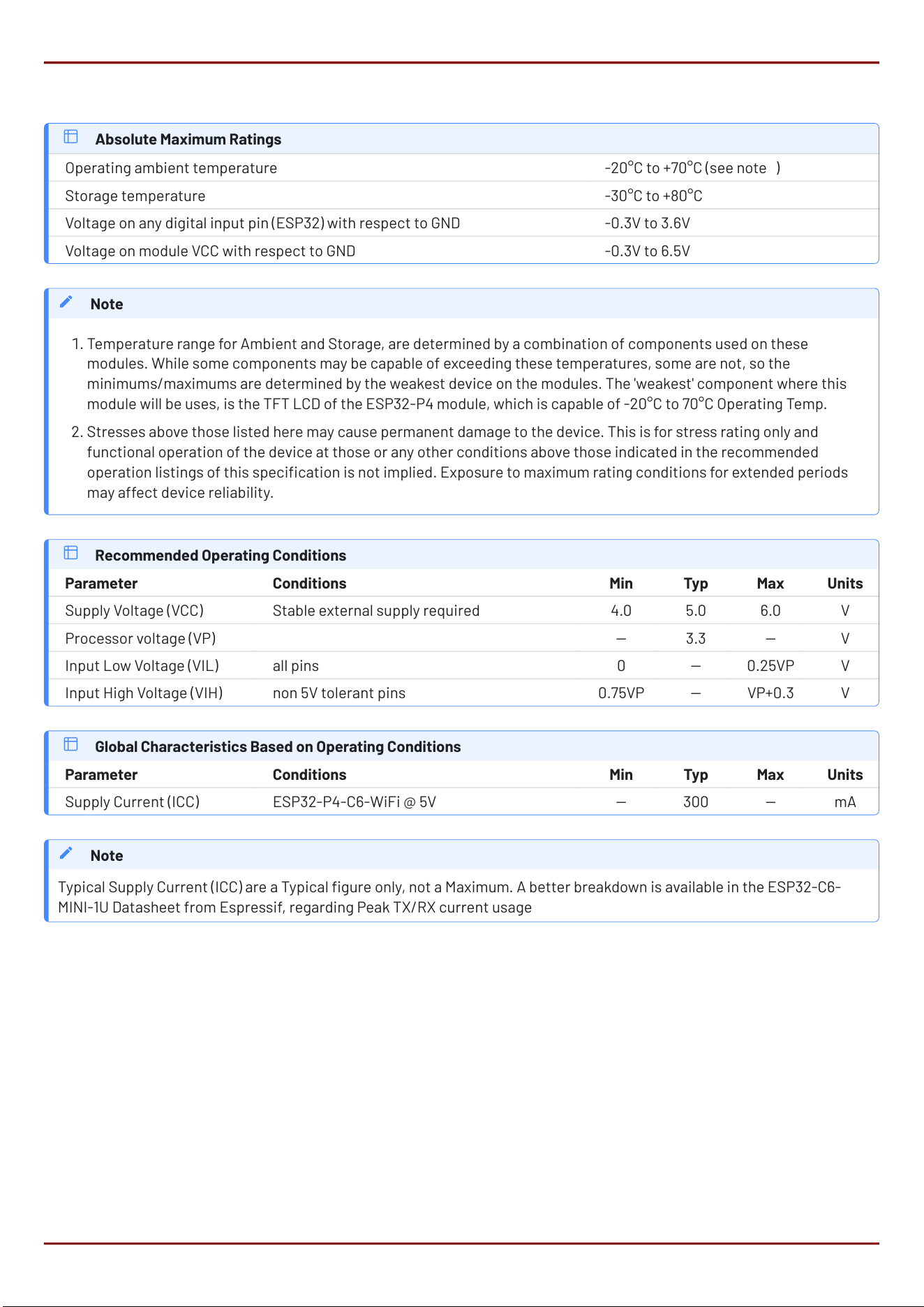
Absolute Maximum Ratings
Operating ambient temperature -20°C to +70°C (see note 1)
Storage temperature -30°C to +80°C
Voltage on any digital input pin (ESP32) with respect to GND -0.3V to 3.6V
Voltage on module VCC with respect to GND -0.3V to 6.5V
Temperature range for Ambient and Storage, are determined by a combination of components used on these
modules. While some components may be capable of exceeding these temperatures, some are not, so the
minimums/maximums are determined by the weakest device on the modules. The 'weakest' component where this
module will be uses, is the TFT LCD of the ESP32-P4 module, which is capable of -20°C to 70°C Operating Temp.
Stresses above those listed here may cause permanent damage to the device. This is for stress rating only and
functional operation of the device at those or any other conditions above those indicated in the recommended
operation listings of this specication is not implied. Exposure to maximum rating conditions for extended periods
may affect device reliability.
Note
1.
2.
Recommended Operating Conditions
Parameter Conditions Min Typ Max Units
Supply Voltage (VCC) Stable external supply required 4.0 5.0 6.0 V
Processor voltage (VP) 3.3 V
Input Low Voltage (VIL) all pins 0 0.25VP V
Input High Voltage (VIH) non 5V tolerant pins 0.75VP VP+0.3 V
Global Characteristics Based on Operating Conditions
Parameter Conditions Min Typ Max Units
Supply Current (ICC) *** ESP32-P4-C6-WiFi @ 5V 300 mA
Typical Supply Current (ICC) are a Typical gure only, not a Maximum. A better breakdown is available in the ESP32-C6-
MINI-1U Datasheet from Espressif, regarding Peak TX/RX current usage
Note
ESP32-C6 WiFi Module Specications
4D Systems
DATASHEET
Page 11 of 13
9. Revision History
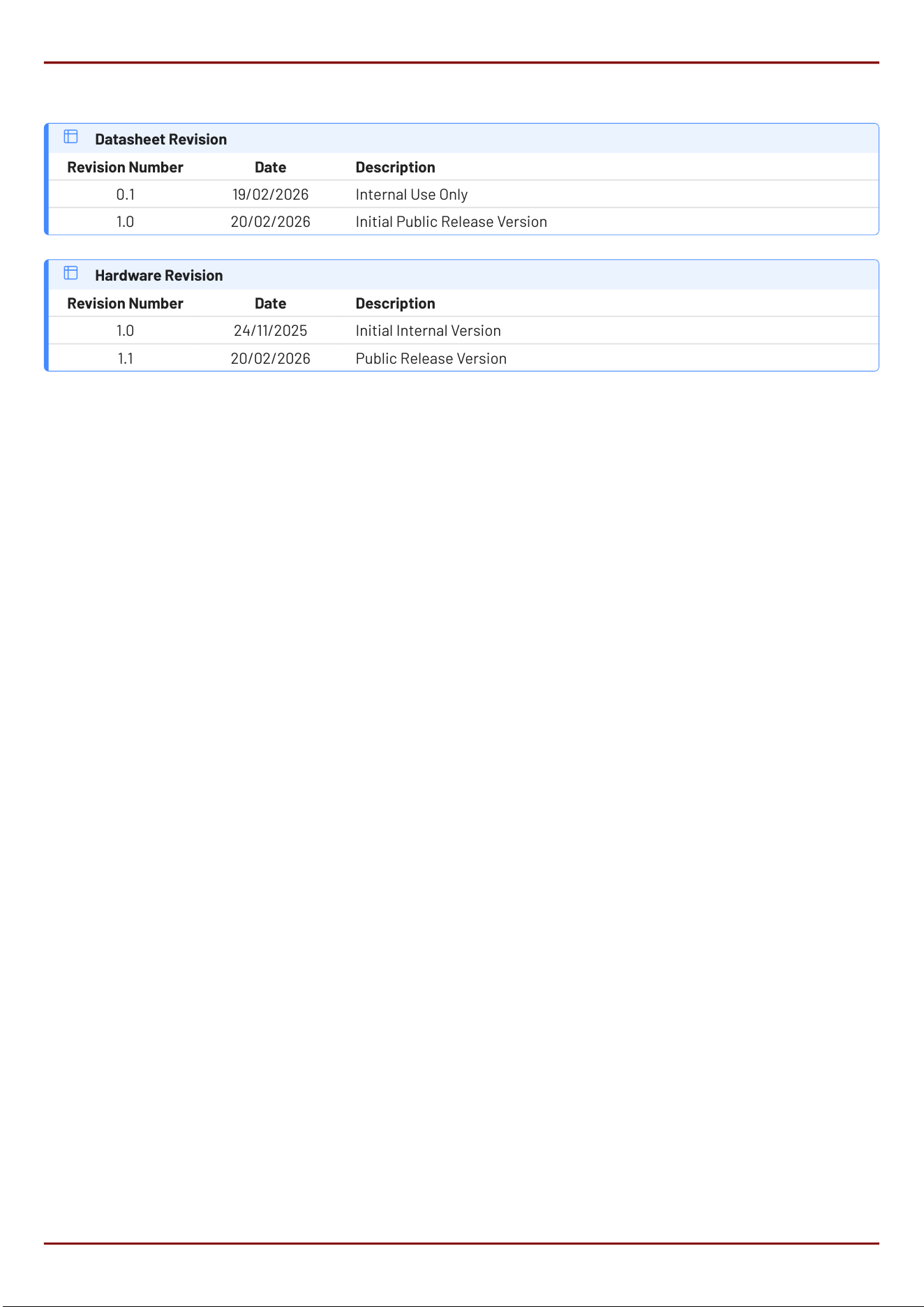
Datasheet Revision
Revision Number Date Description
0.1 19/02/2026 Internal Use Only
1.0 20/02/2026 Initial Public Release Version
Hardware Revision
Revision Number Date Description
1.0 24/11/2025 Initial Internal Version
1.1 20/02/2026 Public Release Version
ESP32-C6 WiFi Module Revision History
4D Systems
DATASHEET
Page 12 of 13

10. Legal Notice
10.1. Proprietary Information
The information contained in this document is the property of 4D Systems Pty. Ltd. and may be the subject of patents
pending or granted, and must not be copied or disclosed without prior written permission. 4D Systems endeavours to ensure
that the information in this document is correct and fairly stated but does not accept liability for any error or omission. The
development of 4D Systems products and services is continuous and published information may not be up to date. It is
important to check the current position with 4D Systems. 4D Systems reserves the right to modify, update or makes changes
to Specications or written material without prior notice at any time.
All trademarks belong to their respective owners and are recognised and acknowledged.
10.2. Disclaimer of Warranties & Limitations of Liabilities
4D Systems makes no warranty, either expressed or implied with respect to any product, and specically disclaims all other
warranties, including, without limitation, warranties for merchantability, non-infringement and tness for any particular
purpose.
Information contained in this publication regarding device applications and the like is provided only for your convenience and
may be superseded by updates. It is your responsibility to ensure that your application meets with your specications.
Images and graphics used throughout this document are for illustrative purposes only. All images and graphics used are
possible to be displayed on the 4D Systems range of products, however the quality may vary.
In no event shall 4D Systems be liable to the buyer or to any third party for any indirect, incidental, special, consequential,
punitive or exemplary damages (including without limitation lost prots, lost savings, or loss of business opportunity) arising
out of or relating to any product or service provided or to be provided by 4D Systems, or the use or inability to use the same,
even if 4D Systems has been advised of the possibility of such damages.
4D Systems products are not fault tolerant nor designed, manufactured or intended for use or resale as on line control
equipment in hazardous environments requiring fail - safe performance, such as in the operation of nuclear facilities, aircraft
navigation or communication systems, air trac control, direct life support machines or weapons systems in which the
failure of the product could lead directly to death, personal injury or severe physical or environmental damage ('High Risk
Activities'). 4D Systems and its suppliers specically disclaim any expressed or implied warranty of tness for High Risk
Activities.
Use of 4D Systems' products and devices in 'High Risk Activities' and in any other application is entirely at the buyer's risk, and
the buyer agrees to defend, indemnify and hold harmless 4D Systems from any and all damages, claims, suits, or expenses
resulting from such use. No licenses are conveyed, implicitly or otherwise, under any 4D Systems intellectual property rights.
ESP32-C6 WiFi Module Legal Notice
4D Systems
DATASHEET
Page 13 of 13

FCC Statement
This device complies with part 15 of the FCC rules. Operation is subject to the following two conditions: (1)
this device may not cause harmful interference, and (2) this device must accept any interference received,
including interference that may cause undesired operation.
Changes or modifications not expressly approved by the party responsible for compliance could void the user’
s authority to operate the equipment.
NOTE: This equipment has been tested and found to comply with the limits for a Class B digital device, pursua
nt to part 15 of the FCC Rules. These limits are designed to provide reasonable protection against harmful inte
rference in a residential installation. This equipment generates uses and can radiate radio frequency energy a
nd, if not installed and used in accordance with the instructions, may cause harmful interference to radio com
munications. However, there is no guarantee that interference will not occur in a particular installation. If this
equipment does cause harmful interference to radio or television reception, which can be determined by turn
ing the equipment off and on, the user is encouraged to try to correct the interference by one or more of the
following measures:
‐ Reorient or relocate the receiving antenna.
‐ Increase the separation between the equipment and receiver.
‐Connect the equipment into an outlet on a circuit different from that to which the receiver is connected.
‐Consult the dealer or an experienced radio/TV technician for help important announcement
Important Note:
Radiation Exposure Statement
This equipment complies with FCC radiation exposure limits set forth for an uncontrolled environment. This
equipment should be installed and operated with minimum distance 20cm between the radiator and your
body.
This transmitter must not be co-located or operating in conjunction with any other antenna or transmitter.
Country Code selection feature to be disabled for products marketed to the US/Canada.
This device is intended only for OEM integrators under the following conditions:
1. The antenna must be installed such that 20 cm is maintained between the antenna and users, and
2. The transmitter module may not be co-located with any other transmitter or antenna,
3. For all products market in US, OEM has to limit the operation channels in CH1 to CH11 for 2.4G band
by supplied firmware programming tool. OEM shall not supply any tool or info to the end-user
regarding to Regulatory Domain change. (if modular only test Channel 1-11)
As long as the three conditions above are met, further transmitter testing will not be required. However, the
OEM integrator is still responsible for testing their end-product for any additional compliance requirements
required with this module installed.
Important Note:
In the event that these conditions cannot be met (for example certain laptop configurations or co-location
with another transmitter), then the FCC authorization is no longer considered valid and the FCC ID cannot be
used on the final product. In these circumstances, the OEM integrator will be responsible for re-evaluating the
end product (including the transmitter) and obtaining a separate FCC authorization.
End Product Labeling
The final end product must be labeled in a visible area with the following"
Contains FCC ID: 2BVVS-ESP32-P4-C6 "
Manual Information to the End User
The OEM integrator has to be aware not to provide information to the end user regarding how to install or
remove this RF module in the user’s manual of the end product which integrates this module.
The end user manual shall include all required regulatory information/warning as show in this manual.

Integration instructions for host product manufacturers according to KDB 996369 D03
OEM Manual v01r01
2.2
List of applicable FCC rules
CFR 47 FCC PART 15.247, 15.207, 15.209 has been investigated. It is applicable to the modular transmitter
2.3
Specific operational use conditions
This module is stand-alone modular. If the end product will involve the Multiple simultaneously transmitting
condition or different operational conditions for a stand-alone modular transmitter in a host, host manufacturer have
to consult with module manufacturer for the installation method in end system.
2.4
Limited module procedures
Not applicable
2.5
Trace antenna designs
Not applicable
2.6
RF exposure considerations
This equipment complies with FCC radiation exposure limits set forth for an uncontrolled environment. This
equipment should be installed and operated with minimum distance 20cm between the radiator & your body.
2.7
Antennas
This radio transmitter FCC ID:2BVVS-ESP32-P4-C6 has been approved by Federal Communications Commission
to operate with the antenna types listed below, with the maximum permissible gain indicated. Antenna types not
included in this list that have a gain greater than the maximum gain indicated for any type listed are strictly prohibited
for use with this device.
Antenna No.
Model No.
of antenna:
Type of antenna:
Gain of the antenna
(Max.)
Frequency
range:
2.4G Wi-Fi
/
External Antenna
2.0
2400-2450MHz
2.8
Label and compliance information
The final end product must be labeled in a visible area with the following" Contains FCC ID:2BVVS-ESP32-P4-C6
".
2.9
Information on test modes and additional testing requirements
Operation Frequency: 2412-2462MHz
Number of Channel: 11
Modulation: DSSS/OFDM
Host manufacturer must perfom test of radiated & conducted emission and spurious emission, etc. according to
the actual test modes for a stand-alone modular transmitter in a host, as well as for multiple simultaneously
transmitting modules or other transmitters in a host product. Only when all the test results of test modes comply
with FCC requirements, then the end product can be sold legally.
2.10
Additional testing, Part 15 Subpart B disclaimer
Host manufacturer is responsible for compliance of the host system with module installed with all other applicable
requirements for the system such as Part 15 B.
2.11
Note EMI Considerations
Host manufacture is recommended to use KDB 996369 D04 Module Integration Guide recommending as "best
practice" RF design engineering testing and evaluation in case non-linear interactions generate additional non-
compliant limits due to module placement to host components or properties.
2.12
How to make changes
This module is stand-alone modular. If the end product will involve the Multiple simultaneously transmitting
condition or different operational conditions for a stand-alone modular transmitter in a host, host manufacturer
have to consult with module manufacturer for the installation method in end system. According to the KDB 996369
D02 Q&A Q12, For EMC/radio-parameter compliance purposes, when an evaluation is done by the grantee or
host provider and there are no additional emissions generated due to simultaneous-transmission operations
compared to single transmitter operations testing (i.e., not transmitting simultaneously), it is not necessary to file
the additional simultaneous transmission test data. The host manufacturer is responsible for ensuring compliance
with the applicable FCC rules for the transmitters operating individually and simultaneously. This includes
compliance for the summation of all emissions from all outputs occupying the same or overlapping frequency
ranges, as defined by the applicable rules.