
DBOX-IOT16 Specification
Page 1 of 20
DBOX-IOT16 Specification
Version
V1.0
Copyright
©2026
WIFI Module

DBOX-IOT16 Specification
Page 2 of 20
Document resume
Version
Date
Develop/revise content
Edition
Approve
V1.0
Initial release

DBOX-IOT16 Specification
Page 3 of 20
Content
1. Product Overview .................................................................................................................. 4
1.1. Features ...................................................................................................................... 5
2. Main Parameters .................................................................................................................... 6
2.1. Electrical parameter ................................................................................................... 6
2.2. Electrical parameter ................................................................................................... 7
2.3. Wi-Fi Radio Performance .......................................................................................... 7
3. Appearance & Package ......................................................................................................... 8
4. Pin Definitions....................................................................................................................... 9
5. Schematic ............................................................................................................................ 11
6. Design Guideline ................................................................................................................. 12
6.1. Application Circuit................................................................................................... 12
6.2. Recommend PCB Package ...................................................................................... 12
6.3. Antenna Layout Requirements ................................................................................ 13
6.4. Power Supply Requirements .................................................................................... 13
6.5. GPIO ........................................................................................................................ 14
7. ROLLING OF Reflow soldering......................................................................................... 15
8. ROLLING OF Reflow soldering......................................................................................... 15
9. Package Information ........................................................................................................... 15
Disclaimer and copyright notice ................................................................................................ 17
Notice ......................................................................................................................................... 17
Statement .................................................................................................................................... 18
DBOX-IOT16 Specification
Page 4 of 20
1. Product Overview
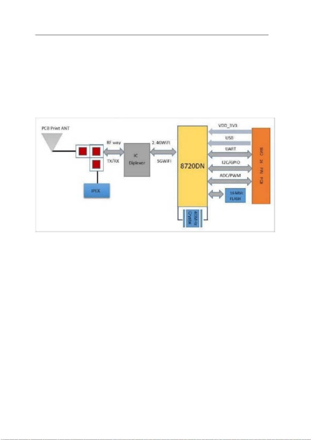
DBOX-IOT16 is a dual-frequency Wi-Fi module based on RTL8720DN. DBOX-IOT16
supports dual-frequency (2.4ghz or 5ghz) WLAN; it integrates ARM V8 (compatible with
Cortex-M4F) high-performance MCU,ARM V8M (compatible with Cortex-M0) low-power
MCU,WLAN(802.11 a / b / g / n), MAC,and RF baseband) and provides a set of configurable
GPIO ports for the control of different peripherals.
Figure 1 Main chip architecture diagram

DBOX-IOT16 Specification
Page 5 of 20
1.1. Features
Support for either 802.11a/b/g/n, 2.4GHz or 5GHz
Supports the HT 20 / HT 40 mode
Supports low power beacon listening mode, low power receiving mode and low power
hanging mode
Built-in AES / DES / SHA hardware engine
Support TrustZone-M and support safe startup
Supports the SWD debug port access protection and disabled modes
Wi-Fi and Bluetooth share the same antenna
Support the STA / AP / STA + AP mode and confounding mode
Support for Android, iOS Simple Config (App) Wi-Fi one-click distribution network
Support for serial port local upgrade and remote firmware upgrade (FOTA)
Support secondary development, support programming in Linux and Windows
environments
Support for Arduino development

DBOX-IOT16 Specification
Page 6 of 20
2. Main Parameters
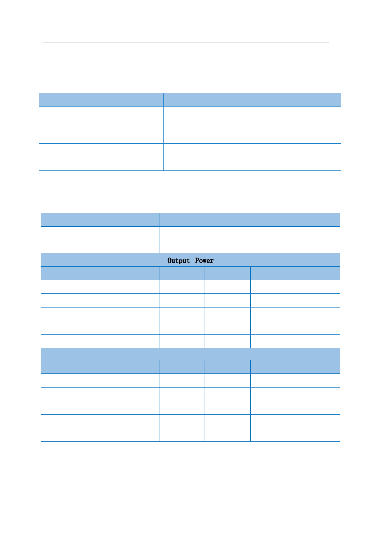
Table 1 Main Parameter
2.1. Electrical parameter
DBOX-IOT16 module is an electrostatic sensitive device, which needs special ES
precautions.When usd ESD protective devices should be added. The correct ESD processing
and packaging must be adopted in the transportation, operation and use of DBOX-IOT16
modules. Do nottouch the module by hand or weld with a non-antistatic soldering iron to avoid
damage to the module.
Figure 2 ESD Warning Logo
Model
DBOX-IOT16
Package
SMD-16
Dimension
24*16*3(±0.2)MM
Antenna
Dipole Antenna
Frequency
2400~2483.5MHz & 5150~5250&5725~5850MHz
Operating Temperature
-40 ℃~85 ℃
Store Temperature
-40 ℃~125 ℃,<90%RH
Power Supply Voltage
3.0V~3.6V, I>500mA
Interface
UART/GPIO/ADC/PWM/IIC/SPI/IR/SWD/USB
Available GPIO
13
UART Baud rates
110~ 6000000 bps,Default 115200bps
Wireless Security
WAPI, WEP, WPA/WPA2/WPA3-PSK, WPA/WPA2/WPA3-EAP
SPI Flash
Default 4MB (Optional 2MB, 8MB, 16MB)
DBOX-IOT16 Specification
Page 7 of 20
2.2. Electrical parameter
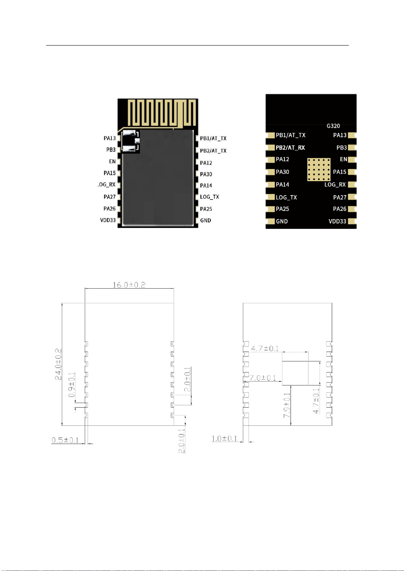
Table 2 Electric Characteristic
2.3. Wi-Fi Radio Performance
Table 3 Wi-Fi Radio Performance
Parameter
Min
Typical
Max
Unit
DC 3.3V (with internal regulator and
integration CMOS PA)
3.0
3.3
3.6
V
Figure I/O supply voltage
1.76
1.8~3.3
3.3
V
DC_IO_33 (3.3V I / O rated current)
-
-
50
mA
Electrostatic protection (VESD)
-
-
2000
V
Description Typical Unit
Operating Frequency
2400~2483.5 and
5150~5250&5725~5850
MHz
Mode Min Typical Max Unit
11a mode,PA output power
6
8
9.5
dBm
11n mode 2.4G,PA output power
13 14.5 16
.5 dBm
11n mode 5G
,
PA output power
6
8
10
dBm
11g mode
,
PA output power
12.5 14
.5
16.5
dBm
11b mode
,
PA output power 14
15 16
dBm
Rx Sensitivity
Mode Min Typical Max Unit
CCK,1Mbps - ≤-90 - dBm
CCK,11Mbps - ≤-85 - dBm
6Mbps(1/2 BPSK) - ≤-88 - dBm
54Mbps(3/4 64-QAM) - ≤-70 - dBm
HT20(MCS7) - ≤-67 - dBm
DBOX-IOT16 Specification
Page 8 of 20
3. Appearance & Package
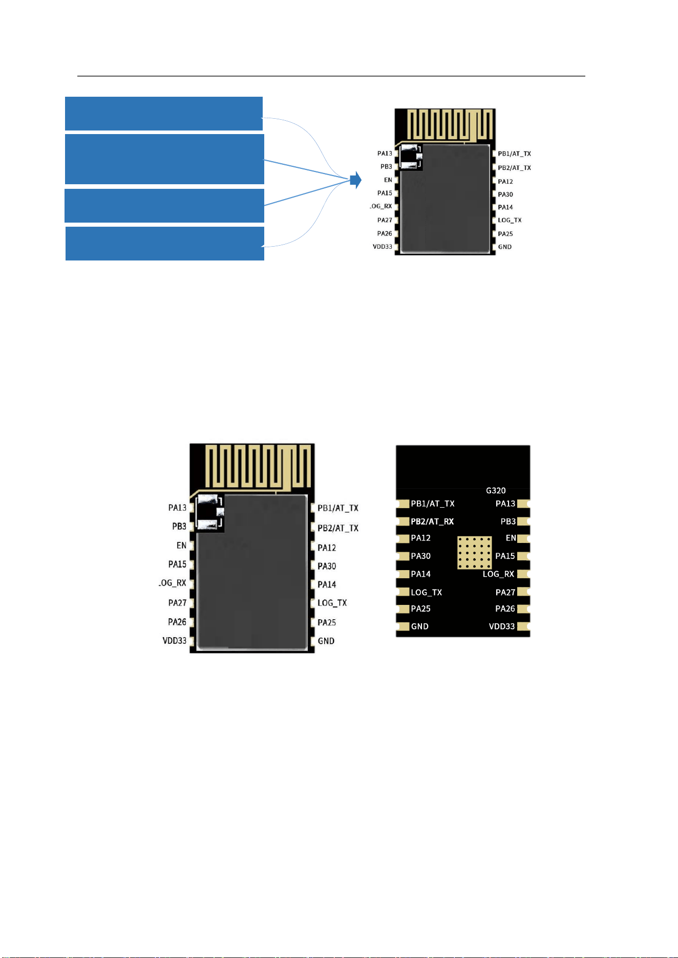
Figure 3 Appearance
Figure 4 Package
Back Front
Front
Back
DBOX-IOT16 Specification
Page 9 of 20
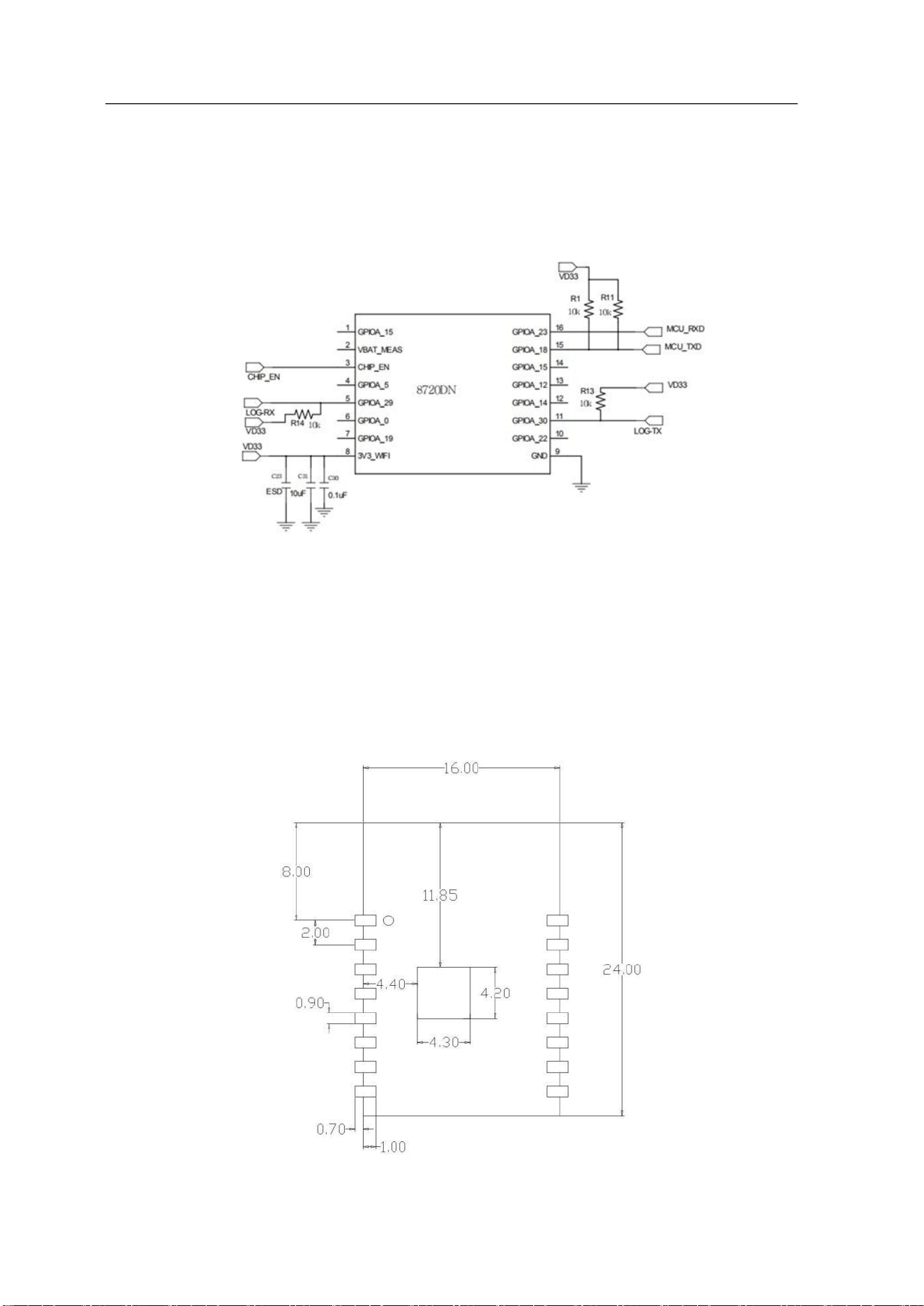
Figure 5 Order Information
4. Pin Definitions
DBOX-IOT16 has 16 interface,refer to following Pin diagram ,Table 2.2 is definition of
interfaces.
Figure 6 Pin out Diagram
Front
Back
U: Support for the USB interface
x: FLASH Size (MB)
H/N: Operating Temperature
H: High Temp N: Normal
F: FLASH

DBOX-IOT16 Specification
Page 10 of 20
Table 5 Pin definitions
No
Name
Description
1
PA13
LP_PWM1/SPI1_MISO
2
PB3
ADC/SWD_CLK
3
CHIP_EN
Chip Enabled
4
PA15
SPI1_CS
5
PA8
UART_LOG_RXD
6
PA27
SWD_DATA
7
PA26
LP_I2C_SDA/LP_PWM5
8
VDD_3V3
3.3V(VDD)
9
GND
Ground
10
PA25
LP_I2C_SCL/LP_PWM4/HSDM
11
PA7
UART_LOG_TXD
12
PA14
SPI1 CLK
13
PA30
LP_PWM1
14
PA12
SPI1_MOSI/LP_PWM0
15
PB2
LP_UART_RXD
16
PB1
LP_UART_TXD
Note: 1. When the LOG _ TX moment is low, the module enters the burning mode; When the
moment is high, the module starts normally and the internal pull up by default.
DBOX-IOT16 Specification
Page 12 of 20
6. Design Guideline
6.1. Application Circuit
Figure 8 Application Circuit
Note:
LOG _ TX is the starting control foot in normal operating mode at high level and burning
firmware mode at low level. Internal chip default high level.
6.2. Recommend PCB Package
Figure 9 Recommend PCB Package
DBOX-IOT16 Specification
Page 13 of 20
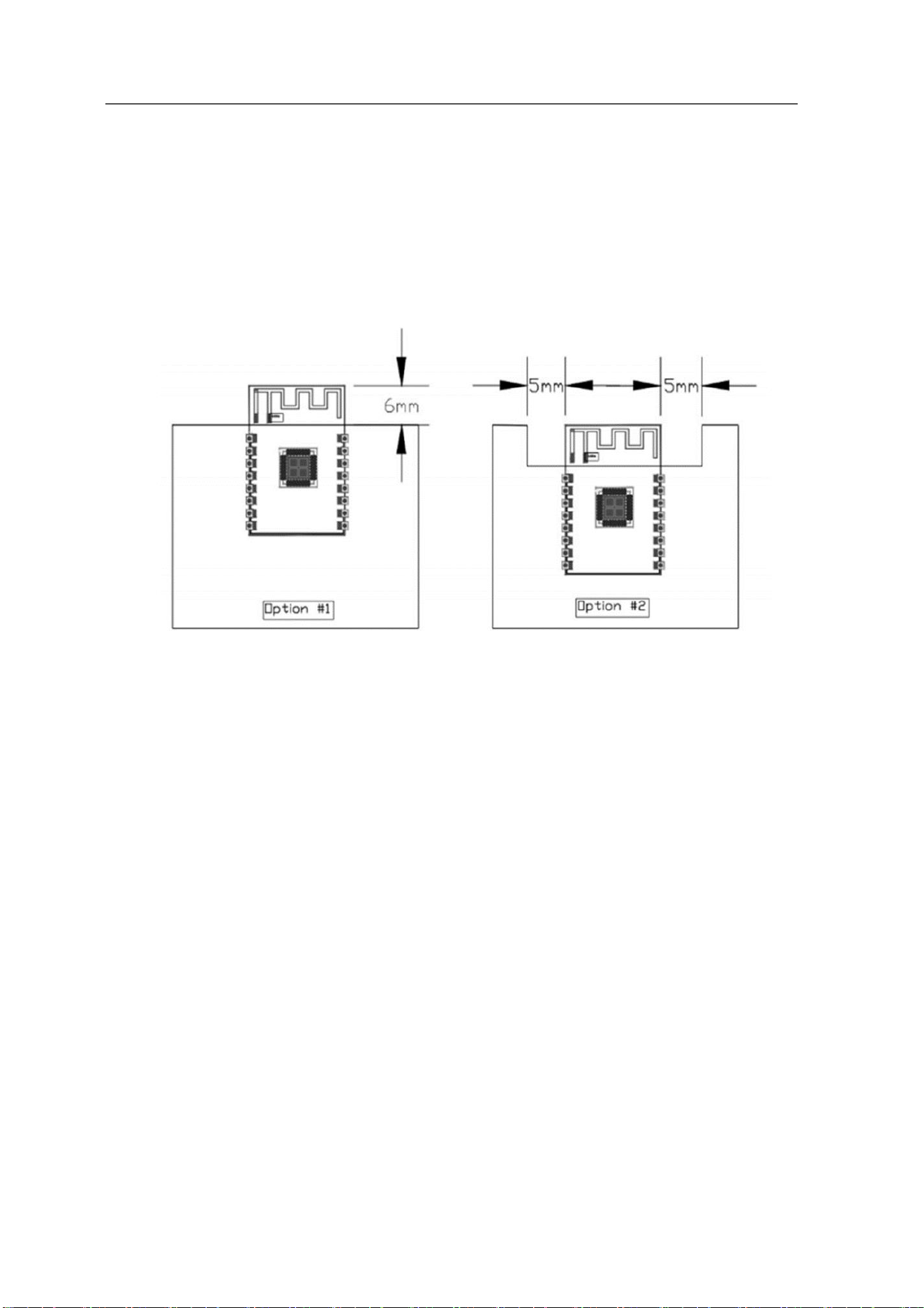
6.3. Antenna Layout Requirements
Installation position on the main board,advise for following two ways:
The module is placed on the edge of the main board, and the antenna area is extended out
of the edge of the main board. 2.In order to meet the performance of the on-board antenna,
metal parts are prohibited from being placed around the antenna.
Figure 10 Schematic diagram of Antenna layout
6.4. Power Supply Requirements
Recommended voltage 5V, Peak:Current over 500mA .
It is recommended to use the LDO power supply;If DC-DC is used, the ripple is
controlled within 30 mV.
DC-DC power supply circuit is recommended to reserve the position of the dynamic
response capacitor, and the output ripple can be optimized when the load change is large.
Proposed addition of ESD Devices to 5V Power supply Interface.
For 3.3V application, if the power up slew rate from 1.5V to 3.0V is slower than 15ms,
The wide range VCC Flash is needed or add reset IC.
In the process of power off to power on, if the power off voltage can't be guaranteed to
drop below 0.3v and power on again, reset IC should be added.
DBOX-IOT16 Specification
Page 14 of 20
6.5. GPIO
At the periphery of the module, some GPIO ports are led out, and a resistance of 10-100
ohms can be connected in series on the IO port for use. This suppresses overshoot and is
more stable on both sides. Help for both EMI and ESD.
For the up-and-down drawing of the special io-port, reference will be made to the use
description of the specification, which will affect the start-up configuration of the module.
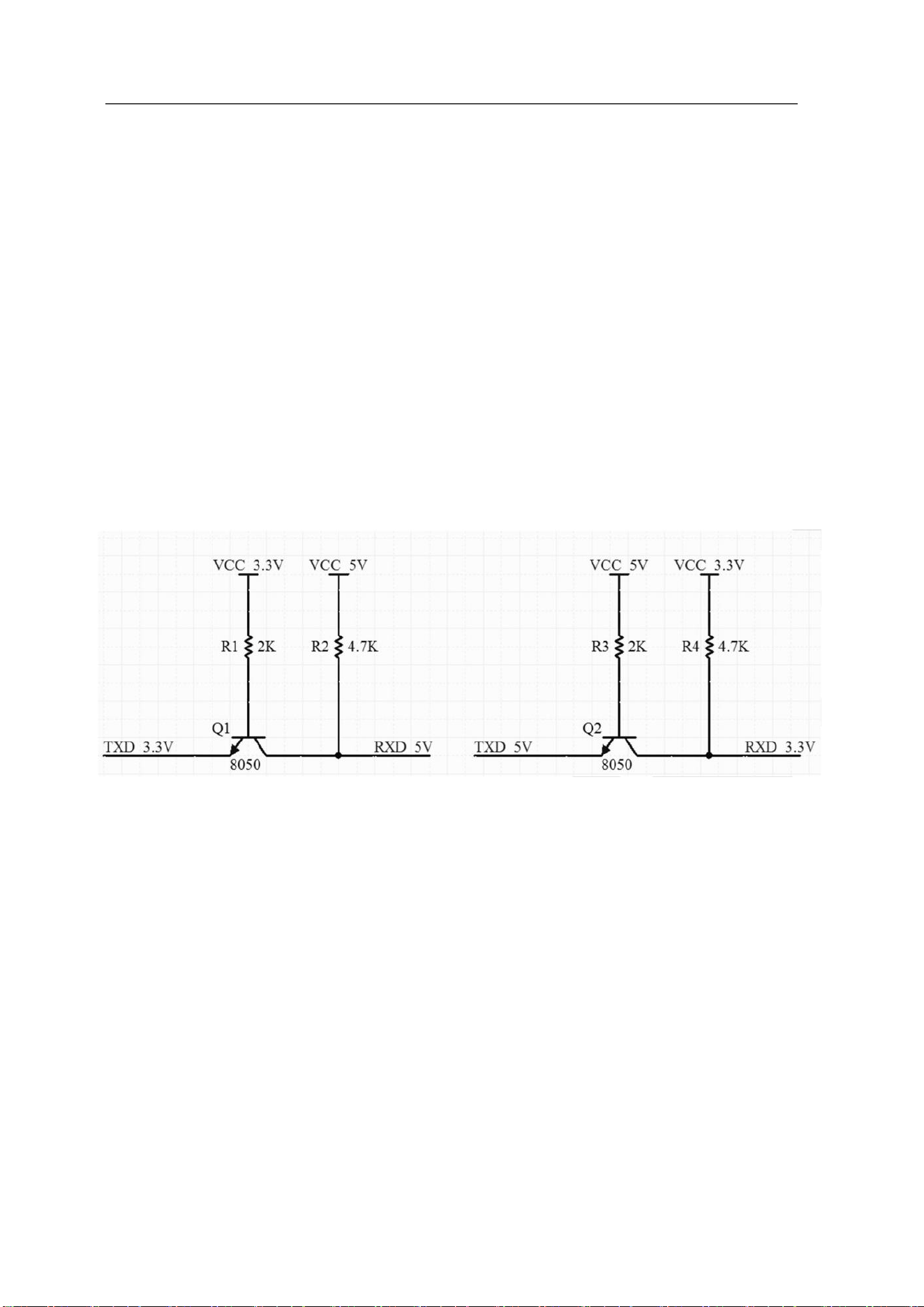
The IO port of the module is 3.3 v. If the main control does not match the io-level of the
module, it is necessary to increase the level conversion circuit.
If the IO interface is directly connected to the peripheral interface, or the pins and other
terminals, it is recommended to reserve the ESD device near the terminal at the IO trace.
Figure 11 switching circuit
DBOX-IOT16 Specification
Page 15 of 20
7. ROLLING OF Reflow soldering
Products sealed in a moisture-proof bag shall be stored in a non-condensing atmosphere of
<40℃ / 90% RH.
The moisture sensitivity grade MSL of the module is level 3.
After the vacuum bag is unsealed, it must be used within 168 hours at 25 ± 5℃ / 60% RH,
otherwise it needs to be baked before the secondary launch.
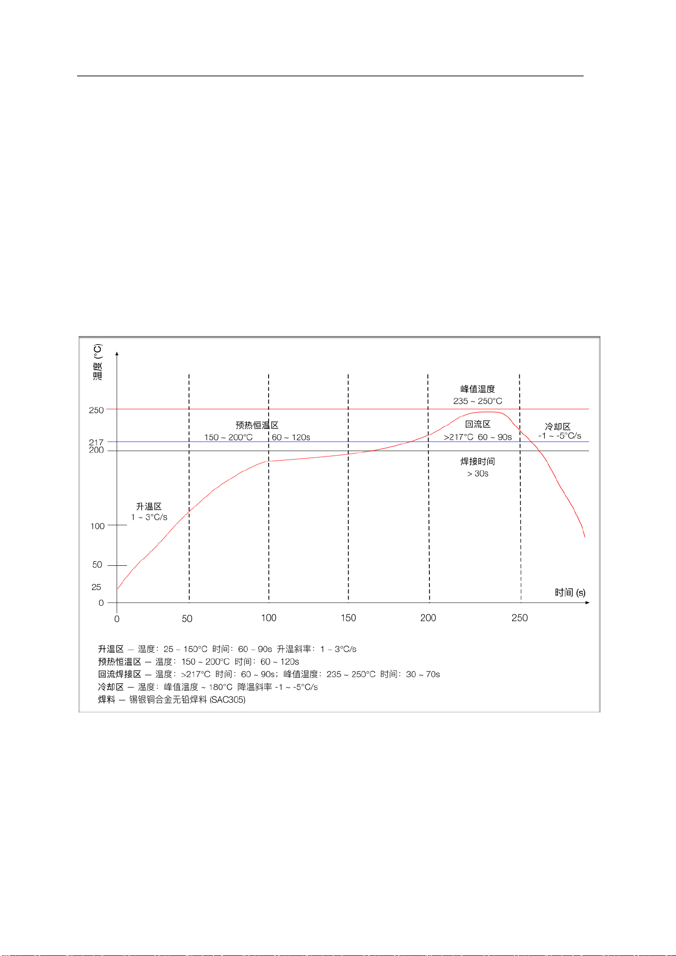
8. ROLLING OF Reflow soldering
Figure12 ROLLING OF Reflow soldering
9. Package Information

DBOX-IOT16 Specification
Page 16 of 20
DBOX-IOT16 module is packaged with 800 pcs / disk. As shown in the figure below:
Figure 13 packing ribbon diagram

DBOX-IOT16 Specification
Page 17 of 20
Disclaimer and copyright notice
The information in this article, including the URL address for reference, is subject to change
without notice.
The document is provided "as is" without any guarantee responsibility, including any guarantee
for merchantability, suitability for a specific purpose, or non-infringement, and any guarantee
mentioned elsewhere in any proposal, specification or sample. This document does not bear
any responsibility, including the responsibility for infringement of any patent rights arising
from the use of the information in this document. This document does not grant any license for
the use of intellectual property rights in estoppel or other ways, whether express or implied.
All brand names, trademarks and registered trademarks mentioned in this article are the
property of their respective owners, and it is hereby declared.

DBOX-IOT16 Specification
Page 18 of 20
Statement
ormation and other resources (the "Resources") "as is" without warranties of any kind,
express or implied. Including, but not limited to, express or implied warranties of suitability,
fitness for a particular use, or non-infringement of any third party's intellectual property
rights.And specifically declares that it is not liable for any necessary or incidental losses,
including but not limited to, arising from the application or the use of any of our products and
circuits.
The Company reserves the right to release information in this document (including but not
limited to metrics and product descriptions) and any changes to our products without prior
notice. This document automatically supersedes and replaces all information provided in
previous versions of the same document number file.
These resources are available to skilled developers who design with products. You are solely
responsible for: (1) Selecting the appropriate products for your application; (2) Design, validate,
and run your application and product throughout its life cycle; (3) Ensure that your application
meets all applicable standards, codes and laws, as well as any other functional security,
information security, regulatory or other requirements.
The Company may authorize you to use these resources only for the development of
applications of Essence Products described in this Resource. Without the permission of the
Company, any unit or individual shall not extract or copy part or all of these resources, and shall
not be transmitted in any form. You are not entitled to use any other the Company intellectual
property rights or any third party intellectual property rights. You shall indemnify you in full for
any claims, damages, costs, losses and liabilities arising against the Company or its
representatives in connection with the use of these resourcese.
The products offered by the Company are subject to the terms of sale of we or other applicable
terms attached to Essence's products. Essence's availability of these resources does not extend or
otherwise change the warranties or warranties disclaimers applicable to product releases.

DBOX-IOT16 Specification
Page 19 of 20
ISED Warning
This device contains licence-exempt transmitter(s) that comply with Innovation, Science and
Economic Development Canada’s licence-exempt RSS(s). Operation is subject to the following
two conditions:
1.This device may not cause interference.
2.This device must accept any interference, including interference that maycause undesired
operation of
the device.
The device for operation in the band 5150–5250 MHz is only for indoor use
The module is tested for standalone mobile RF exposure use conditions. The distance between
user and products should
be no less than 20cm.
Any other usage conditions such as co-location with other transmitter(s) or in a portable
condition will need to be separate reassessment through ISED rules or new certification.
If the IC number is not visible when the module is installed inside another device, then the
outside of the device into which the module is installed must also display a label referring to the
enclosed module. This exterior label can use wording such as the following: “Contains IC:
35639-DBOXIOT16”
This equipment must be installed and operated in accordance with provided instructions, and the
antenna(s) used for this transmitter must not be collocated or operating in conjunction with any
other antenna or transmitter. End-users and installers must be provided with antenna installation
instructions and transmitter operating conditions for satisfying RF exposure compliance. ISED :
Cet appareil contient des émetteurs exempts de licence qui sont conformes aux RSÉ exempts de
licence d’Innovation, Sciences et Développement économique Canada. Son utilisation est
soumise aux deux conditions suivantes :

DBOX-IOT16 Specification
Page 20 of 20
1.Cet appareil ne doit pas causer d'interférences.
2.Cet appareil doit accepter toutes les interférences, y compris celles pouvant provoquer un
fonctionnement indésirable de l'appareil.
L'appareil destiné à fonctionner dans la bande 5150–5250 MHz est uniquement destiné à un
usage en intérieur
Le module est testé pour des conditions d'exposition RF mobiles autonomes. La distance entre
l'utilisateur et les produits ne doit pas être inférieure à 20 cm.
Toutes les autres conditions d'utilisation, telles que le co-emploi avec d'autres émetteurs ou en
condition portable, nécessiteront une réévaluation distincte conformément aux règles ISED ou
une nouvelle certification.
Si le numéro IC n'est pas visible lorsque le module est installé à l'intérieur d'un autre appareil,
l'extérieur de l'appareil dans lequel le module est installé doit également afficher une étiquette
faisant référence au module intégré. Cette étiquette extérieure peut utiliser une formulation telle
que : « Contient IC : 35639-DBOXIOT16 »
Cet équipement doit être installé et utilisé conformément aux instructions fournies, et l'(les)
antenne(s) utilisée(s) pour cet émetteur ne doivent pas être co-localisées ou fonctionner
conjointement avec d'autres antennes ou émetteurs. Les utilisateurs finaux et les installateurs
doivent recevoir des instructions d'installation de l'antenne et des conditions de fonctionnement
de l'émetteur pour garantir la conformité à l'exposition RF.
This radio transmitter [ Contient IC : 35639-DBOXIOT16 ] has been approved by Innovation,
Science and EconomicDevelopment Canada to operate with the antenna types listed below,
with the maximum permissible gain indicated.Antenna types not included in this list that have a
gain greater than the maximum gain indicated for any type listed are strictly prohibited for use
with this device.
Immediately following the above notice, the manufacturer shall provide a list of all antenna
types which can be used withthe transmitter indicating the maximum permissible antenna gain
(in dBi) and the required impedance for each antenna type.
Antenna manufacturer: Kunshan Jinkang Electronics Co., LTD
Antenna model: KC-DBOX16 Antenna Type: External Antenna
Antenna gain: 2.4G:3.0dBi 5G Band1:2.75dBi; 5G Band4:2.00dBi;

Basic FCC Compliance Statement
This device complies with part 15 of the FCC Rules. Operation is subject to the following two
conditions: (1) This device may not cause harmful interference (2) This device must accept any
interference received, including interference that may cause undesired operation.
FCC WARNING
Any Changes or modifications not expressly approved by the party responsible for compliance could
void the user's authority to operate the device.
Note: This device has been tested and found to comply with the limits for a Class A digital device,
pursuant to part 15 of the FCC Rules. These limits are designed to provide reasonable protection
against harmful radio frequency interference when operated in a commercial environment. This device
generates, uses and can radiate radio frequency energy and, if not installed and used in accordance
with the instructions, may cause harmful interference to radio communications. However, there is no
guarantee that interference will not occur in a particular installation.
If this device does cause harmful interference to radio or television reception, which can be determined
by turning the device off and on, the user is encouraged to try to correct the interference by one or
more of the following measures:
• Reorient or relocate the receiving antenna.
• Increase the separation between the device and receiver.
• Connect the device into an outlet on a circuit different from that to which the receiver is
connected.
• Consult the dealer or an experienced radio/TV technician for help.
RF Radiation Exposure Requirement (Per KDB996369 D03)
2.2 List of applicable FCC rules
List the FCC rules that are applicable to the modular transmitter. These are the rules that specifically
establish the bands of operation, the power, spurious emissions, and operating fundamental
frequencies. DO NOT list compliance to unintentional-radiator rules (Part 15 Subpart B) since that is
not a condition of a module grant that is extended to a host manufacturer. See also Section 2.10 below
concerning the need to notify host manufacturers that further testing is required. Explanation: This
module meets the requirements of FCC part 15C(15.247、15.407).
2.3 Summarize the specific operational use conditions
Describe use conditions that are applicable to the modular transmitter, including for example any limits
on antennas, etc. For example, if point-to-point antennas are used that require reduction in power or

compensation for cable loss, then this information must be in the instructions. If the use condition
limitations extend to professional users, then instructions must state that this information also extends
to the host manufacturer's instruction manual. In addition, certain information may also be needed,
such as peak gain per frequency band and minimum gain, specifically for master devices in 5 GHz DFS
bands.
Explanation: The EUT has a external antenna, Antenna support 2.4GHz WIFI and 5GHz WIFI,The
module have an unique antenna connector, 2.4G antenna gain is 3dBi.5GHz WIFI antenna gain is
U-NII 1: 2.75dBi U-NII 3: 2.00dBi
2.4 Limited module procedures
If a modular transmitter is approved as a "limited module", then the module manufacturer is
responsible for approving the host environment that the limited module is used with. The
manufacturer of a limited module must describe, both in the filing and in the installation instructions,
the alternative means that the limited module manufacturer uses to verify that the host meets the
necessary requirements to satisfy the module limiting conditions.
A limited module manufacturer has the flexibility to define its alternative method to address the
conditions that limit the initial approval, such as: shielding, minimum signaling amplitude, buffered
modulation/data inputs, or power supply regulation. The alternative method could include that the
limited module manufacturer reviews detailed test data or host designs prior to giving the host
manufacturer approval.
This limited module procedure is also applicable for RF exposure evaluation when it is necessary to
demonstrate compliance in a specific host. The module manufacturer must state how control of the
product into which the modular transmitter will be installed will be maintained such that full
compliance of the product is always ensured. For additional hosts other than the specific host originally
granted with a limited module, a Class II permissive change is required on the module grant to register
the additional host as a specific host also approved with the module.
Explanation: The module is not a limited module.
2.5 Trace antenna designs
For a modular transmitter with trace antenna designs, see the guidance in Question 11 of KDB
Publication 996369 D02 FAQ - Modules for Micro-Strip Antennas and traces. The integration
information shall include for the TCB review the integration instructions for the following aspects:
layout of trace design, parts list (BOM), antenna, connectors, and isolation requirements. a) Information
that includes permitted variances (e.g., trace boundary limits, thickness, length, width, shape(s),
dielectric constant, and impedance as applicable for each type of antenna); b) Each design shall be
considered a different type (e.g. antenna length in multiple(s) of frequency, the wavelength, and
antenna shape (traces in phase) can affect antenna gain and must be considered); c) The parameters
shall be provided in a manner permitting host manufacturers to design the printed circuit (PC) board
layout; d) Appropriate parts by manufacturer and specifications; e) Test procedures for design

verification; f) Production test procedures for ensuring compliance.
The module grantee shall provide a notice that any deviation(s) from the defined parameters of the
antenna trace, as described by the instructions, require that the host product manufacturer must notify
the module grantee that they wish to change the antenna trace design. In this case, a Class II
permissive change application is required to be filed by the grantee, or the host manufacturer can take
responsibility through the change in FCC ID (new application) procedure followed by a Class II
permissive change application.
Explanation: Not applicable
2.6 RF exposure considerations
It is essential for module grantees to clearly and explicitly state the RF exposure conditions that permit
a host product manufacturer to use the module. Two types of instructions are required for RF
exposure information: (1) to the host product manufacturer, to define the application conditions
(mobile portable - 20 cm from a person's body); and (2) additional text needed for the host product
manufacturer to provide to end users in their end-product manuals.
If RF exposure statements and use conditions are not provided, then the host product manufacturer is
required to take responsibility for the module through a change in FCC ID (new application).
Explanation: The module must be installed in the host equipment such that at least 20cm is
maintained between the antennaand users' body; and if RF exposure statement or module layout is
changed, then the host product manufacturerrequired to take responsibility of the module through a
change in FCC ID or new application. The FCC ID of themodule cannot be used on the final product.
In these circumstances, the host manufacturer will be responsiblefor re-evaluating the end product
(including the transmitter) and obtaining a separate FCC authorization
2.7 Antennas
A list of antennas included in the application for certification must be provided in the instructions. For
modular transmitters approved as limited modules, all applicable professional installer instructions
must be included as part of the information to the host product manufacturer. The antenna list shall
also identify the antenna types (monopole, PIFA, dipole, etc. Note that an "omnidirectional antenna" is
not considered to be a specific "antenna type").
For situations where the host product manufacturer is responsible for an external connector, for
example, with an RF pin and antenna trace design, the integration instructions shall inform the installer
that a unique antenna connector must be used on the Part 15 authorized transmitters used in the host
product. The module manufacturers shall provide a list of acceptable unique connectors.
Explanation: The EUT has a external antenna, Antenna support 2.4GHz WIFI and 5GHz WIFI,The
module have an unique antenna connector, 2.4G antenna gain is 3dBi.5GHz WIFI antenna gain is
U-NII 1: 2.75dBi U-NII 3: 2.00dBi

2.8 Label and compliance information
Grantees are responsible for the continued compliance of their modules to the FCC rules. This includes
advising host product manufacturers that they need to provide a physical or e-label stating "Contains
FCC ID" with their finished product. See Guidelines for Labeling and User Information for RF Devices -
KDB Publication 784748.
Explanation: The host system using this module should have label in a visible area indicated the
following texts: "Contains FCC ID: 2BV7U-DBOXIOT16"
2.9 Information on test modes and additional testing requirements
Additional guidance for testing host products is given in KDB Publication 996369 D04 Module
Integration Guide. Test modes should take into consideration different operational conditions for a
stand-alone modular transmitter in a host, as well as for multiple simultaneously transmitting modules
or other transmitters in a host product.
The grantee should provide information on how to configure test modes for host product evaluation for
different operational conditions for a stand-alone modular transmitter in a host, versus with multiple,
simultaneously transmitting modules or other transmitters in a host. Grantees can increase the utility of
their modular transmitters by providing special means, modes, or instructions that simulates or
characterizes a connection by enabling a transmitter. This can greatly simplify a host manufacturer's
determination that a module as installed in a host complies with FCC requirements.
Explanation: The OEM integrator is responsible for ensuring that the end-user has no manual
instruction to remove or install module.
The module is limited to installation in mobile application, a separate approval is required for all other
operating configurations, including portable configurations with respect to §2.1093 and difference
antenna configurations.
2.10 Additional testing, Part 15 Subpart B disclaimer
The grantee should include a statement that the modular transmitter is only FCC authorized for the
specific rule parts (i.e., FCC transmitter rules) listed on the grant, and that the host product
manufacturer is responsible for compliance to any other FCC rules that apply to the host not covered
by the modular transmitter grant of certification. If the grantee markets their product as being Part 15
Subpart B compliant (when it also contains unintentional-radiator digital circuity), then the grantee shall
provide a notice stating that the final host product still requires Part 15 Subpart B compliance testing
with the modular transmitter installed.
Explanation: The module without unintentional-radiator digital circuity, so the module does not require
an evaluation by FCC Part 15 Subpart B. The host shoule be evaluated by the FCC Subpart B.
2.11 Note EMI Considerations
Host manufacture is recommended to use D04 Module Integration Guide recommending as "best
practice"RF design engineering testing and evaluation in case non-linear interactions generate
additional noncompliantlimits due to module placement to host components or properties.
2.12 How to make changes
This module is stand-alone modular. If the end product will involve the Multiple simultaneously
transmittingcondition or different operational conditions for a stand-alone modular transmitter in a
host, hostmanufacturer have to consult with module manufacturer for the installation method in end
system. Accordingto the KDB 996369 D02 Q&A Q12, that a host manufacture only needs to do an
evaluation (i.e., no C2PCrequired when no emission exceeds the limit of any individual device (including
unintentional radiators) as acomposite. The host manufacturer must fix any failure.If you need to do
C2PC, please contact Shanghai Quicktron Automation Technology Co., Ltd.
Email:[email protected]