24
AUTHORISED DEALER
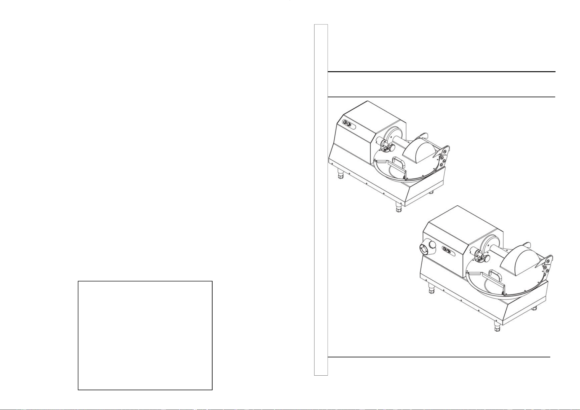
CUTTER 6
CUTTER 12
Ed. 01/2015
HORIZONTAL CUTTERS
USE AND MAINTENANCE MANUAL
2 23
9 Troubleshooting
9.1 - Troubleshooting
Problem(s) Cause(s) Solution(s)
The machine does not
start.
The circuit breaker is set to "0".
The lid is not locked.
The tank is missing.
The cutter’s tank or lid
microswitch is not working.
The electric motor or the
electrical board are defective.
The buttons will not start the
blades.
Turn the main switch to
"1".
Lower the lid and turn
the knob counter-
clockwise.
Assemble the tank,
fastening it correctly to
the pull mechanism.
Contact customer
service.
Contact customer
service.
Contact customer

22
After every work shift:
- Thoroughly clean the machine by removing any processing residue.
- Remove, clean and replace the blades and tank.
8.6 - Cleaning the machine
At the end of each work shift, thoroughly clean the machine and disinfect it if neces-
sary (Chapter 6.3.2).
- Stop the machine, switch the circuit breaker installed upstream of the mixer to "0"
and detach the power plug.
- With a sponge soaked in water and neutral and non-toxic degreasing products, re-
move all processing residue from the machine.
Do not use gasoline, solvents or other flammable liquids as detergents; instead, use
authorised commercial solvents (non-toxic solvents and non-flammable).
Adapt the guards to be used when cleaning and disinfecting the machine based on the
type of solvent. Follow the instructions of the cleaning products.
Adeguare le protezioni da utilizzare nella pulizia e disinfezione in base al prodotto
adottato. Seguire le istruzioni dei prodotti utilizzati.
IMPORTANT!
The cutter has been designed and manufactured to process meat and vegetables;
therefore, it is compulsory to use non-toxic and neutral detergents that are suitable to
disinfect components used to process foodstuffs.
8.7 - Lubrication
The transmission gearbox is greased for life and therefore does not have to be re-
placed from time to time.
8.8 - Replacement of spare parts
Contact your local dealer should you need to order spare parts. Do not use spare
parts that are not original. Please remember that the machine must be assembled by
qualified personnel only.
3
INDEX
1. Delivery and warranty 5
1.1 - Introduction
1.2 - Storage and use of the manual
1.3 - Warranty
1.4 - Description of the machine
1.5 - Intended use
1.6 - Improper use
1.7 - Machine identification
1.8 - Safety guards and devices
1.9 - Warning and danger signs/labels
1.10 - Operating position
1.10 - Environmental conditions
1.12 - Lighting
1.13 - Vibrations
1.14 - Protective equipment
2. Technical characteristics 10
2.1 - Main parts
2.2 - Technical specifications
2.3 - Size and weight of the machine
2.4 - Wiring diagrams
2.4.1 - Wiring diagram of single-phase stainless steel buttons
2.5 - Noise level emitted by the machine
3. Testing, transport, delivery and installation 13
3.1 - Testing
3.2 - Delivery and handling of the machine
3.2.1 - BOM included with machine
3.3 - Installation site
3.3.1 - Installation
3.3.2 - Packaging disposal
3.3.3 - Handling the machine
3.4 - Electrical connection
3.4.1 - Single phase 110 Volt-60 Hz machine
4. Controls and indicators 15
4.1 - List of controls and indicators
5. Starting and stopping the machine 16
5.1 - Checking the electrical connection
5.2 - Checking for presence and efficiency of safety guards and devices
5.3 - Machine start-up
5.4 - Machine stop

4
5.5 - Inversion
6. Use of the machine 17
6.1 - Persons authorised to operate the machine
6.2 - Operating mode of the cutter
6.3 - Emptying and cleaning the tank
6.3.1 - Emptying the tank
6.3.2 - Cleaning the tank
6.3.3 - Assembling the tank
6.4 - Disassembling and adjusting the blades
7. Optionals 20
7.1 - Power take-off (PTO)
8. Maintenance 20
8.1 - Maintenance instructions
8.2 - Introduction
8.3 - Checks carried out at our manufacturing plant
8.4 - Checks and inspections to be carried out during installation
8.5 - Routine checks
8.6 - Cleaning the machine
8.7 - Lubrication
8.8 - Replacement of spare parts
9. Troubleshooting 23
9.1 - Troubleshooting
21
parts.
8.3 - Checks carried out at our manufacturing plant
The manufacturer has conducted a number of tests on the machine in your posses-
sion, in order to ensure correct commissioning and include the necessary adjust-
ments.
In particular, the manufacturer has performed the following checks:
Before commissioning:
- Control of the operating voltage of the machine: the voltage must be the same re-
quested by the buyer.
- Checking for the presence of all the warning signs/labels and the rating plate with
the technical specifications and serial number.
- Checking of tightness of all bolts and nuts.
- Compliance of the machine to the applicable regulations/standards and to the in-
structions provided in this manual.
With the machine in operation:
- Checking of the efficiency of the safety devices and guard; the machine must stop
when the operator opens the grille.
- General operating control.
- Execution of repeated tests in order to verify the machine’s set-up, according to the
type of work it will be used for.
8.4 - Checks and inspections to be carried out during installation
To make sure that the machine has not been damaged during transport or installation,
make sure that you diligently perform the checks and inspections listed below:
Before commissioning:
- Check that the voltage corresponds to the value shown on the machine identifica-
tion plate.
- Check for the presence and integrity of the warning and danger signs/labels.
- Check the integrity of the power cable.
- Check that the safety devices, such as magnetic sensors, are intact.
Checks with machine in operation:
- Check the efficiency of the safety guards and devices. These may have been dam-
aged or impaired during transport.
- Perform a few test runs with products of the same size of the material you will then
process.
8.5 - Routine checks
To maintain the features and reliability of your machine consistent over time, you
should perform additional checks and inspections (besides those described hitherto)
with the frequency listed below.
Before each work shift:
- Check the operation of the safety devices - daily.
- Check the integrity of the power cable.
IMPORTANT!
If the machine does not stop when you open the lid or in the event of other malfunc-
tions, request the assistance of customer service.
20
7 Optionals
7.1 - Power take-off (PTO)
The customer can request to have a PTO in-
stalled in order to attach the meat grinder to it
(this option must be requested when placing
the order). The PTO installed will rotate
counter-clockwise at approximately 190 RPM.
8 Maintenance
8.1 - Maintenance instructions
IMPORTANT! All maintenance and cleaning of the mixer should be performed only
when the machine is stopped and with the plug disconnected from the power supply.
The area where you perform maintenance operations must always be kept clean, dry
and well-lit. Do not allow unauthorised personnel to perform operations on the ma-
chine. Do not access articulated, sharp and uncontrolled openings of the machine
with the body, limbs or fingers, and without adequate protective equipment and guards
(appropriate gloves, goggles, etc.) Do not use gasoline, solvents or other flammable
liquids as detergents: instead, use authorised commercial solvents )non-toxic and non
-flammable).
Do not use compressed air to clean the machine If you absolutely must use com-
pressed air, protect yourself with goggles having side guards and limit the pressure to
a maximum of 2 atm. (1.9 bar). Do not use open flames for lighting when performing
inspections and maintenance on the machine.
8.2 - Introduction
Good maintenance and proper use are essential requirements to ensure the efficiency
and safety of the mixer To ensure regular and constant operation and to avoid invali-
dation of the warranty, machine components must be replaced only with original spare
1
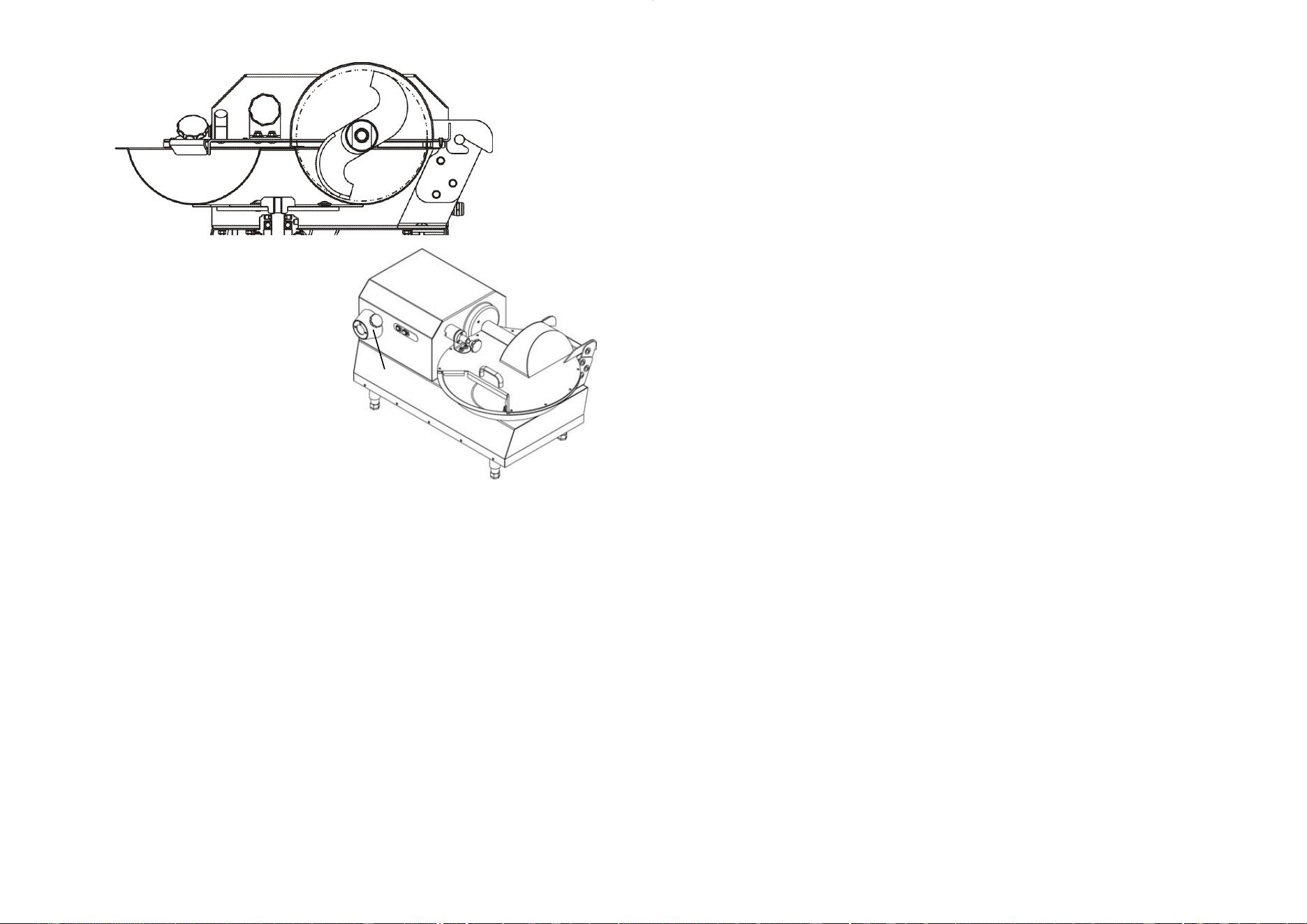
Fig. 7.1.1
Fig. 6.4.3
5
1 Delivery and warranty
1.1 - Introduction
The symbols used in this manual are meant to draw the reader's attention to a set of
points and operations that are potentially dangerous to the personal safety of opera-
tors or that entail the risk of damaging the machine. Do not operate the machine
unless you are certain that you fully understand the instructions and guidelines high-
lighted in the notes.
IMPORTANT!
For the sake of clarity, some illustrations in this manual depict the machine or parts of
it with the panels or casings removed. Do not use the machine under such conditions,
but only if all of the guards are assembled correctly and are working perfectly. The
manufacturer prohibits the reproduction, even partial, of this manual, and its contents
may not be used for any purpose other than those explicitly authorised by the manu-
facturer. Any infringement will be prosecuted according to law.
1.2 - Storage and use of the manual
The purpose of this manual is to inform the users of the machine by means of texts
and detailed illustrations of the rules and essential guidelines for transporting, han-
dling, use and maintenance of the machine. Carefully read this manual before using
the machine.
Store it carefully near the machine, in a place that is easily and quickly accessible for
any future reference. If the manual is lost or damaged, request a copy from your
dealer or directly from the manufacturer.
In the event of transfer of the machine, be sure to inform the manufacturer of the con-
tact details and address of the new owner. The manual reflects the state of the art at
the time the machine was introduced on the market and cannot be considered inade-
quate if updated versions are issued as a result of technological progress. Regarding
the above, the manufacturer reserves the right to update the production and associ-
ated manuals without the obligation to update previous productions and manuals,
unless in exceptional cases.
In case of doubt, consult your nearest service centre or the manufacturer directly. The
manufacturer is committed to continuously improving the state of the art of its product
(s).
For this reason, the manufacturer welcomes any suggestions from its customers that
may help improve the machine and/or the manual. The machine was delivered to the
user under the warranty conditions valid at the time of purchase. Please contact your
supplier if you wish to receive clarifications or more information.
1.3 - Warranty
Under no circumstances is the user authorised to tamper with the machine. Should
you uncover malfunctions or flaws, contact the manufacturer. Any attempt to disas-
semble, modify or more generically tamper with any component of the machine by the
user or by unauthorised personnel will result in the revocation of the Declaration of
conformity issued pursuant to EC Directive 2006/42, will invalidate the warranty and
relieve the manufacturer of any liability for damages to persons and property caused
by such attempts.
The manufacturer shall also consider itself relieved of any responsibility in the follow-
ing cases:
6
• improper installation;
• improper use of the machine by inadequately trained staff;
• use of the machine contrary to the regulations/standards in force in the country of
use;
• lack of or negligent maintenance;
• use of non-original spare parts and non-specific for the model;
• total or partial inobservance of the instructions.
1.4 - Description of the machine
The cutter in your possession is a simple machine with high performance and power
output. Because it must be used to mince and mix food products, the components that
may come in contact with the product have been carefully chosen to ensure the high-
est level of hygiene. The blades on all models are built in stainless steel AISI 420 to
ensure longer durability and maximum hygiene.
Operations for emptying the tank:
• set the circuit breaker upstream of the machine to "0",
• turn the release knob on the lid counter-clockwise,
• open the lid,
• turn the lock knob of the blade holder,
• remove the blade holder,
• turn the tank counter-clockwise,
• lift the tank.
The controls are placed in an easily accessible location and consist of two 24V but-
tons. Special care was applied when designing the machine to ensure that operators
can perform cleaning tasks with ease, in particular thanks to the following construc-
tional features:
• simple removal of the propeller without the need for tools,
• all electrical parts manufactured according to a minimum degree of protection IP 56.
The models depicted in this manual were built in accordance with EC Directive
2006/42 as amended. In the event of an accident, no responsibility can be charged to
the manufacturer if the machine has been altered or tampered with, if its safety guards
have been removed or if the machine is used for purposes not intended by the manu-
facturer.
1.5 - Intended use
The machine was designed and built for shredding, mincing and mixing meat for sau-
sages and vegetables.
It must be used in professional environments and staff assigned to its use must be a
skilled operator in the sector that must have read this manual carefully before using
the machine. We recommend installing the cutter indoors, protected from weather and
from strong fluctuations in temperature.
19
6.3.3 - Assembling the tank
To assemble the tank, perform the procedure described in the previous paragraph in
reverse order, paying attention to re-assemble the tank in its correct position.
- Insert the tank "5" (Fig. 6.3.8) in the drag plate.
- Turn the tank clockwise to lock it into place
- Insert the blade holder “4” (Fig. 6.3.9) on the shaft
- Tighten the lock knob of the blade holder “3” (Fig. 6.3.9).
- Lower the lid "2" (Fig. 6.3.9).
- Rotate the lid release knob “1” clockwise (Fig. 6.3.10).
Fig. 6.3.8
5
Fig. 6.3.9
3
4
2
Fig. 6.3.10
1
6.4 - Disassembling and adjusting the blades
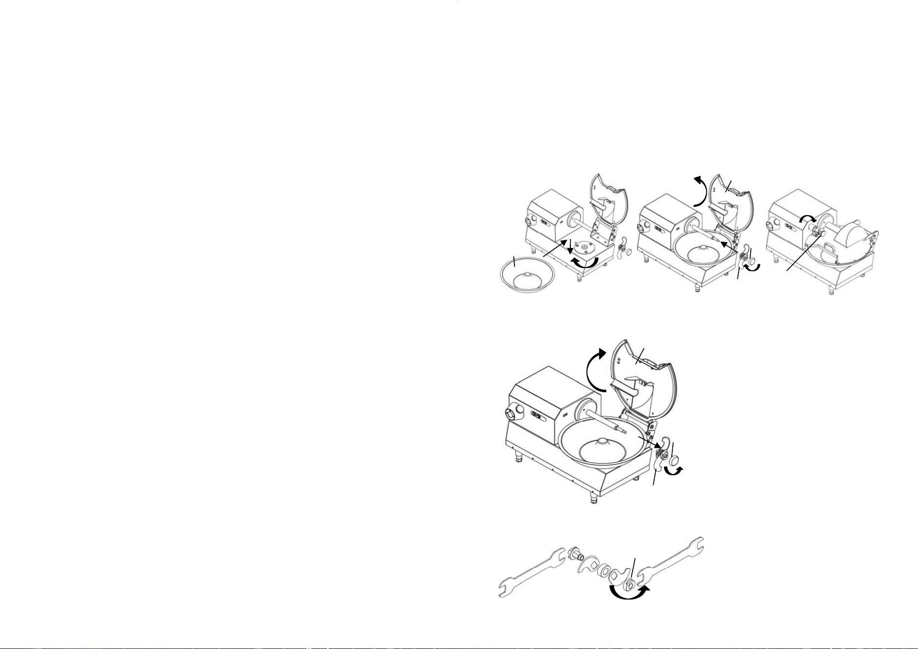
To disassemble the blade holder, proceed as follows:
- Switch off the machine, set the cir-
cuit breaker to "0" and remove the
power plug
- Unlock the lid and lift it, as de-
scribed in par. 6.3.1
- Unscrew the knob "2" (Fig. 6.4.1)
- Remove the blade holder “3” (Fig.
6.4.1)
- Using two wrenches, unscrew the
ring nut "4" (Fig. 6.4.2)
- Adjust the blades so that they are
more or less level with the bottom
of the tank, depending on the mate-
rial you intend to introduce in the
cutter.
- Now, clamp the blade holder and
reposition it on the shaft.
- Lock the blade holder with the knob
"2" (Fig. 6.4.1)
- Rotate the shaft by hand to check
that the blades do not touch the
bottom of the tank. If they do, re-
peat the adjustment.
Fig. 6.4.1
2
3
1
Fig. 6.4.2
4
18
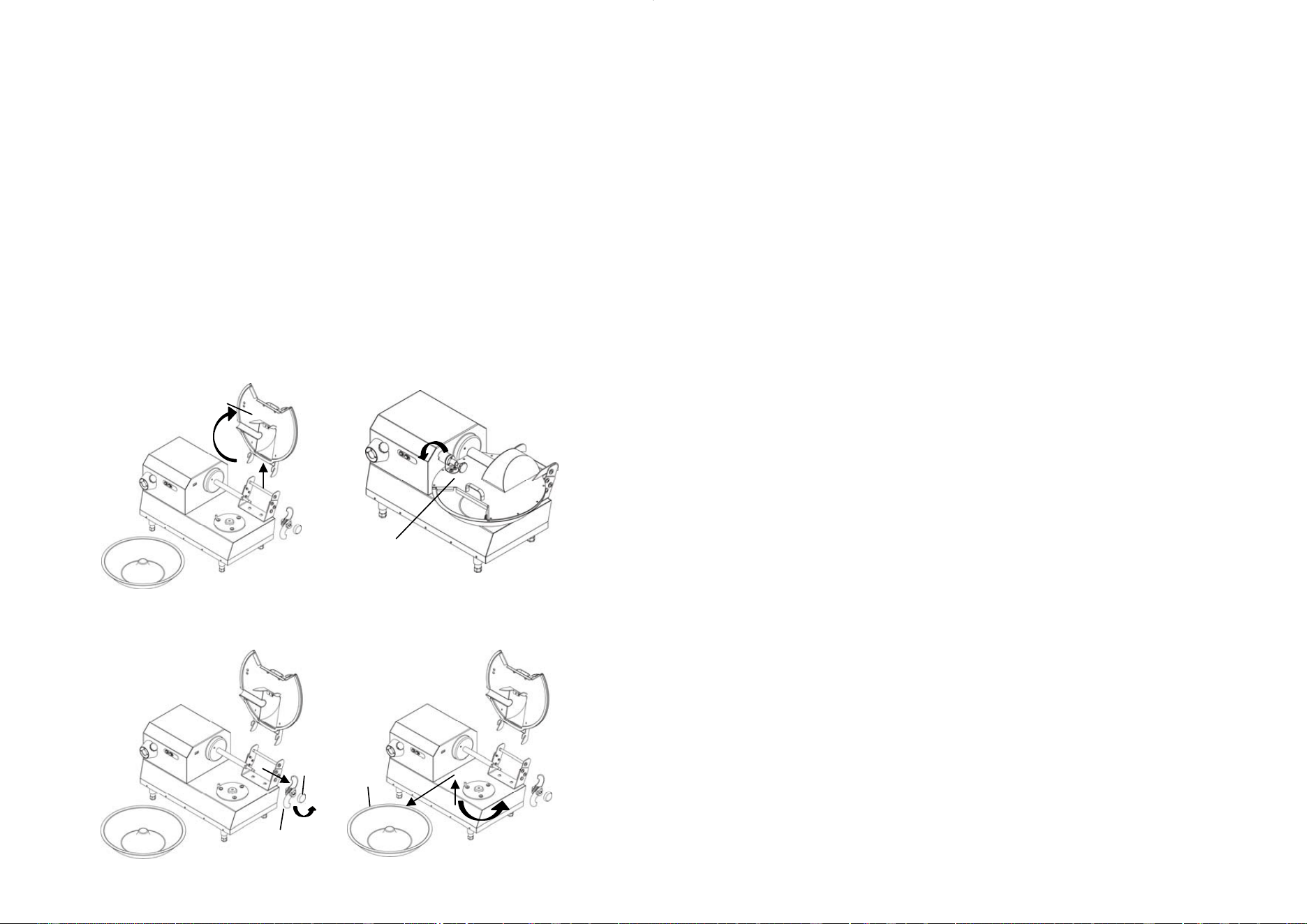
6.3.2 - Cleaning the tank
With the machine off, the circuit breaker set to "0" and the power plug detached, clean
the tank.
- Rotate the lid release knob “1” counter-clockwise (Fig. 6.3.1).
- Raise the lid "2" (Fig. 6.3.2) and extract it from its seat.
- Turn the lock knob of the blade holder “3” (Fig. 6.3.3
- Remove the blade holder from the shaft “4” (Fig. 6.3.3
- Turn the tank “5” counter-clockwise (Fig. 6.3.4) in order to release it from its seat
- Lift and remove the tank
- The surface is now smooth and easy to clean. (Fig. 6.3.4).
- Proceed to thoroughly clean the machine and disinfect it if necessary.
- With a sponge soaked in water and neutral (pH 7) and non-toxic degreasing prod-
ucts, remove all processing residue from the machine and blades.
Do not use gasoline, solvents or other flammable liquids as detergents; instead, use
authorised commercial solvents (non-toxic solvents and non-flammable).
Adapt the guards to be used when cleaning and disinfecting the machine based on the
type of solvent. Follow the instructions of the cleaning products.
Fig. 6.3.7
5
Fig. 6.3.4
1
Fig. 6.3.5
2
Fig. 6.3.6
3
4
7
IMPORTANT!
The size of the product to be mixed must be such as to fit entirely in the tank and
never exceed the weight of 4 Kg (for cutter 6) and of 8.5 kg (for cutter 12).
1.6 - Improper use
The cutter must only be used for the purposes approved by the manufacturer; more
specifically:
- Do not use the machine to mix foodstuffs other than meat or vegetables.
- Do not use the machine if it is not properly installed with all the safety guards intact
and assembled correctly, in order to avoid the risk of severe personal injury.
- Do not access the electrical components without having previously cut-off power
supply to the machine: doing so entails the risk electrocution.
- Do not process products in quantities exceeding the total capacity of the tank.
- Do not wear clothing that does not comply with the applicable accident prevention
regulations. Consult your employer as to the applicable safety regulations and safety
devices to be used.
- Do not start the machine if it is malfunctioning. Before using the machine, make sure
that you have removed/solved any safety-threatening condition. If you notice any
kind of malfunction or flaw, stop the machine and warn those responsible for main-
tenance.
- Do not allow unauthorised personnel to perform operations on the machine. Urgent
treatment in case of an accident caused by electric current requires first of all pulling
the injured person away from the machine (as the person will have likely lost con-
sciousness). This is a hazardous operation. The injured person in this case is an
electric conductor: touch him means getting electrocuted. It is advisable to discon-
nect the contacts directly from the line valve or, if this is not possible, to move the
victim using insulating materials (sticks of wood or PVC, fabric, leather, etc.).
It is advisable to have medical staff intervene immediately and to hospitalise the vic-
tim.
- Do not use the machine in environments where there are gases in the atmosphere
that involve a high chance of combustion.
- Do not perform any operation without prior authorisation.
- Follow the procedures given for maintenance and technical assistance.
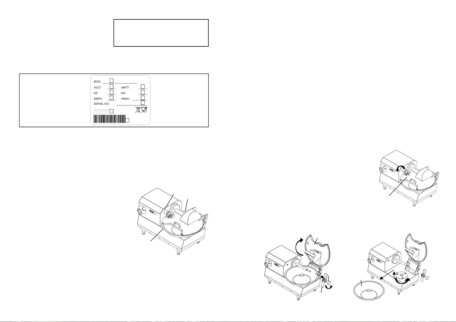
8
1.7 - Machine identification
An exact description of the "Model", the
"Serial number" and the "Year of manu-
facture" will allow our customer service to
provide quick and efficient responses.
Please specify the machine model and the serial number whenever you contact our
customer service. This information is printed on the rating plate (see Fig. 1.7.1. We
suggest you keep track of the machine’s identification details by filing out the boxed
frame shown below.
IMPORTANT!
Do not under any circumstances alter the data printed on the rating plate.
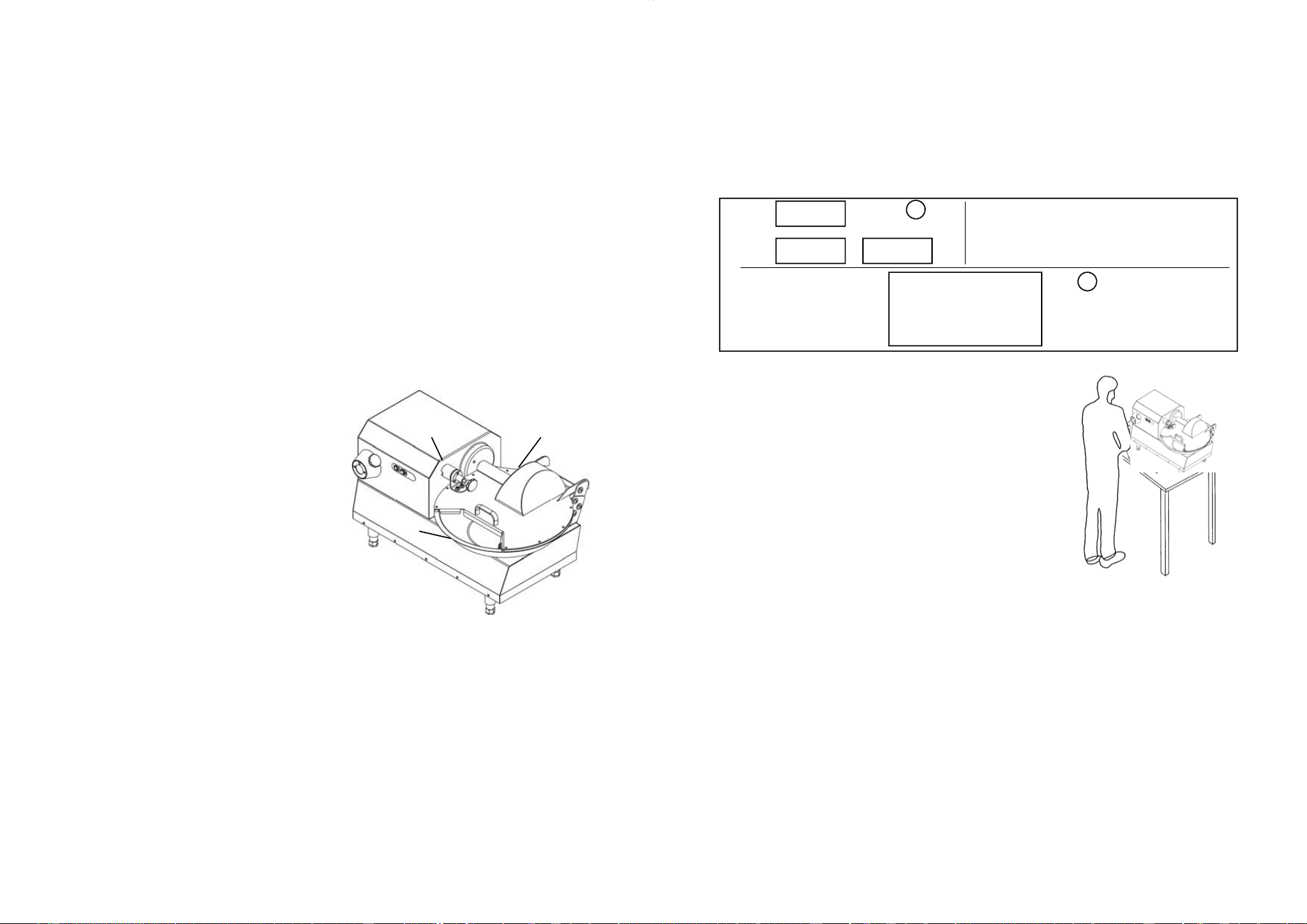
1.8 - Safety guards and devices
IMPORTANT!
Before starting the machine, make sure that the safety devices are in place and intact.
Check for their presence and efficiency at the begin-
ning of each work shift. If the safety devices are not
installed and/or are inefficient, contact the Mainte-
nance Manager.
1. - Tool protective lid.
The purpose of the lid is to prevent accidental
contact of the hands with the tool. (Fig. 1.8.1)
2 - Microswitches (Fig. 1.8.1):
2a lid,
2b tank (both installed).
IMPORTANT!
Do not under any circumstances tamper with the safety devices.
Model...................................................
Serial number......................................
Year of manufacture............................
Type.....................................................
Fig. 1.7.1 Fig. 1.7.1
Fig. 1.8.1
1
2a
2b
A = Model of the machine
B = Power supply
C = Engine power
D = Engine frequency (Hz)
E = Weight
F = Amperage
G = Year of manufacture
H = Serial number
I = Manufacturer
L = Barcode
A
B C
D E
F G
H
I
L
17
5.4 - Machine stop
To stop the machine, press button "2" (stops the electric motor). Then, switch the cir-
cuit breaker installed upstream of the machine to "0", thereby disconnecting the cutter.
6 Use of the machine
6.1 – Persons authorised to operate the machine
IMPORTANT!
Only authorised staff can intervene on the machine.
Before using the machine, the operator must ensure that all guards are in place and
that the safety devices are installed and efficient. Otherwise, turn the machine off and
contact the person in charge of maintenance.
Make sure there is sufficient lighting to allow proper visibility to the operator. Run the
machine idle a couple of times with the assistance of qualified personnel, in order to
familiarise with the machine enough to operate it safely.
6.2 - Operating mode of the cutter
To load products onto the cutter, the circuit breaker must be switched to "0" (off). The
product to be minced must fit in the tank and must not exceed the maximum weight
indicated in this manual. Close the lid (locking it by turning the knob counter-
clockwise) and start the machine (see chapter 5).
6.3 - Emptying and cleaning the tank
6.3.1 - Emptying the tank
Turn off the machine, set the circuit breaker to "0"
and detach the power plug.
- Rotate the lid release knob "1" counter-clockwise (Fig.
6.3.1).
- Raise the lid "2" (Fig. 6.3.2).
- Turn the lock knob of the blade holder “3” (Fig. 6.3.2).
- Remove the blade holder “4” (Fig. 6.3.2) from the shaft
- Turn the tank “5” counter-clockwise (Fig. 6.3.3) in order to release it from its seat
- Lift and remove the tank
- Proceed to empty out the tank by removing the shredded product
Fig. 6.3.1
1
Fig. 6.3.3
5
Fig. 6.3.2
3
4
2
16
5 Starting and stopping the machine
5.1 - Checking the electrical connection
Switch the circuit breaker installed upstream of the machine to "I".
Press the start button ("1" Fig. 4.1.1), checking the direction of rotation of the tools
(380 three-phase version).
The blades must turn clockwise.
If the direction of rotation is counter-clockwise, disconnect the machine from the power
supply and contact the dealer nearest to you.
Note:
In machines connected to a single-phase line and configured for this type of power
supply, the correct direction of rotation is defined directly by the manufacturer.
5.2 - Checking for presence and efficiency of safety guards and devices
1 - Tool protective lid (Fig. 5.2.1)
Visually check for the presence and integ-
rity of the protective lid.
2- Microswitches (Fig. 5.2.1)
2a - with machine running, turn the lid lock
knob counter-clockwise: the machine must
stop.
2b - remove the tank and try starting the
cutter: the machine must not work.
If it does when performing this operation,
contact an authorised dealer or directly the
manufacturer.
IMPORTANT! In the case of absence, defects or incorrect adjustment of the casing,
or in case of incorrect functioning of the safety devices listed above, turn the machine
off and contact customer service to restore the machine to its original settings.
5.3 - Machine start-up
Turn the circuit breaker that supplies power to the machine from "0" to "1". Press start
button "1" (Fig. 4.1.1), thus activating tool rotation.
2a
1
Fig. 5.2.1
2b
9
1.9 - Warning and danger signs/labels
IMPORTANT!
Do not intervene on the electrical components whenever the machine is connected to
the electrical network. Doing so entails a serious risk of electrocution. Comply with
the warnings indicated on the signs/labels. Failure to comply with the warnings
may cause personal injury and even death.
Make sure that the signs/labels are intact and clearly legible. If otherwise, re-attach or
replace them.
1.10 - Operating position
The correct position of the operator in order to work
efficiently with the mixer is shown in Fig. 1.10.1.
1.11 - Environmental conditions
The machine is designed to operate in the following
environmental conditions:
- minimum ambient temperature: -5 °C;
- maximum ambient temperature: +40 °C;
- relative humidity: 50% at 40 °C.
1.12 - Lighting
The place of installation of the mixer must have sufficient natural light and artificial
lighting in accordance with the regulations/standards in force in the country of installa-
tion. In any case, the lighting must conform to the regulations/standards in force in the
country where the machine is delivered and must not create hazardous reflections.
The lighting should allow the operator to clearly read the control panels and identify
the buttons to start/stop the machine.
1.13 - Vibrations
The machine does not transmit significant vibrations.
1.14 - Protective equipment
No specific protective equipment is required. We recommend using safety rubber
gloves that are suitable for processing foodstuffs
230 VOLT
Fig. 1.9.2
IMPORTANT!
REMEMBER TO UNPLUG
THE MACHINE FROM ITS POWER
SUPPLY
BEFORE PERFORMING ANY TYPE OF
MAINTENANCE
400 VOLT
A
C
Fig. 1.10.1
110 VOLT
10
2 Technical characteristics
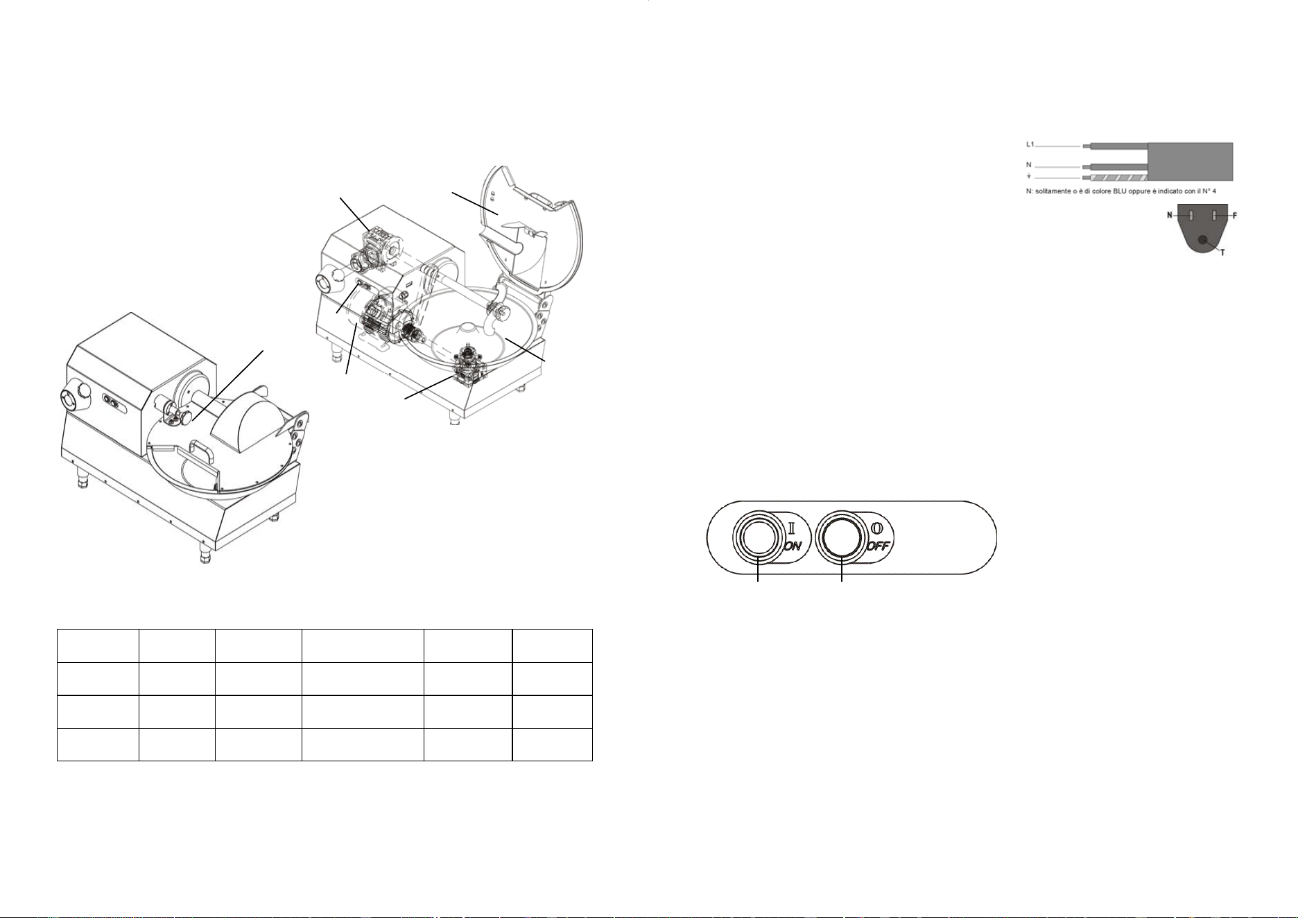
2.1 - Main parts
To facilitate understanding of the manual, the main components of the machine are
listed and shown in the Fig. 2.1.1 Main parts of the machine.
1. Electric motor;
2. Lid unlocking knob;
3. Tank;
4. Cutter (blades);
5. Lid;
6. Controls;
7. Tank gearbox;
8. PTO gearbox
(optional for cutter 12).
2.2 - Technical specifications
model
Motor Ampere Power supply I/L Capacity
Watt/Hp A Volt/Hz mm lt/Kg
6 370/0,5 3,5 110/60 71/ø430 6/4,5
12 750/1 7 110/60 91,5/ø505 12/9
Fig. 2.1.1
1
6
3
8
5
7
4
15
3.4.1 - Single phase 110 Volt-60 Hz machine
In this set-up, the machine is supplied with a power cable with section 3 x 1.5 mm.
This cable is connected to a single-phase three-pole plug. Fasten the cable to the sin-
gle-phase power network (220V-50 Hz) with a magneto-thermal circuit-breaker (16
Amp).
For machine set-ups with different voltages, please consult the manufacturer,(in these
cases, the machine is supplied without a mains plug).
If you need to stretch the power cable, use a cable of the same section as the one in-
stalled by the manufacturer.
For instructions on how to check the proper electrical connection, see par. 5.1.
4 Controls and indicators
4.1 - List of controls and indicators
1 - Start button (continuous)
- Press the button to start the machine.
2 - Stop button
- Press the button to stop the machine.
Fig. 4.1.1
1 2
14
3.3 – Installation site
IMPORTANT!
The site where you intend to install the machine must be solid and horizontal and the
base must be sturdy enough to withstand its weight safely.
In addition, the machine must have ample space around it (overall encumbrance), as
shown in Fig. 2.4.1. This allows the operator greater manoeuvrability during work and
will facilitate future maintenance.
Provide sufficient lighting around the machine, in order to ensure proper visibility to the
operator who is using the mixer.
3.3.1 - Installation
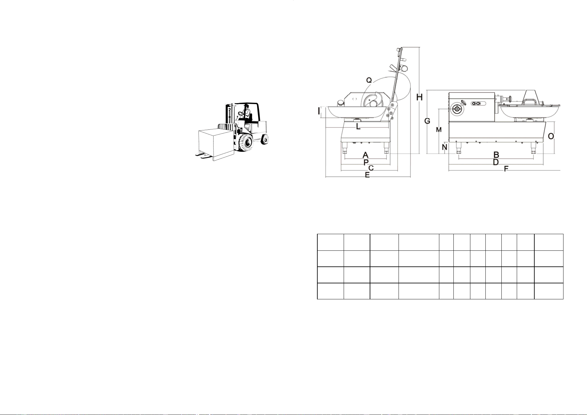
Use a forklift or other similar equipment to handle the pack-
age, as the machine is supplied on a pallet protected with
cardboard.
Remove the two straps that hold the cardboard box fas-
tened to the pallet.
Remove the cardboard.
Remove the cellophane wrapped around the machine
and any other packing material inside.
3.3.2 - Packaging disposal
Packing components like cardboard, nylon and wood are products comparable to solid
urban waste, which makes them freely disposable.
If the machine is delivered in countries where there are particular requirements for
waste disposal, dispose of the packaging in accordance with the regulations/standards
in force.
3.3.3 – Handling the machine
Lift the machine with a forklift of suitable capacity.
Check the stability and position of the load on the forks, especially along rough, slip-
pery or titled surfaces. During handling, keep the load as low as possible to ensure
greater stability and visibility. Widen the forks to stabilise the grip as much as possible.
At least two operators are required to manually handle the mixer.
3.4 - Electrical connection
IMPORTANT!
Check that the power supply corresponds to the value shown on the machine identifi-
cation plate. All tasks on electrical components must be carried out only by special-
ised personnel that is expressly authorised by the on-site manager in charge. Connect
the machine to a network with efficient earthing.
Fig. 3.3.1
11
2.3 - Size and weight of the machine
model
AxB CxD ExFxG H M N O P Q Weight
mm mm mm mm mm mm mm mm kg
6 297x540 356x714 516x833x470 766 / 92 247 356 100° 60
12 335x600 394x759 587x902x512 854 440 92 255 395 100° 75
12
Fig. 2.4.1
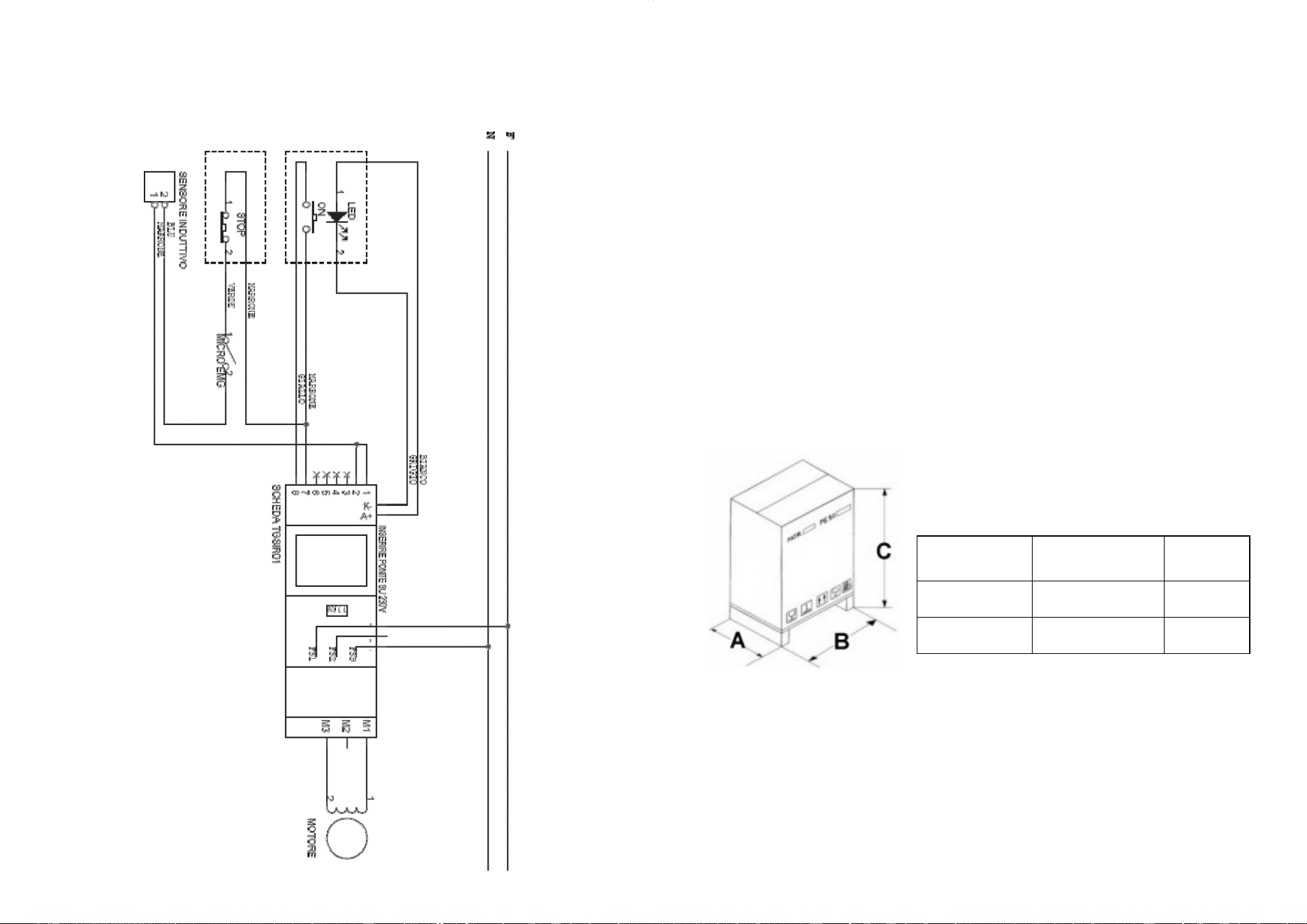
2.4 - Wiring diagrams
2.4.1 - Wiring diagram of single-phase stainless steel buttons
13
2.5 - Noise level emitted by the machine
The measured noise level emitted by the machine is equivalent to less than 70 dBA.
On request, the manufacturer can provide a copy of the noise test.
3 Testing, transport, delivery and installation
3.1 - Testing
The machine in your possession has been tested at our manufacturing plant in order
to ensure its proper operation and adjustment. The testing process involves tests on
material that is identical to the one the machine operator will use.
3.2 - Delivery and handling of the machine
All the material shipped to customers was carefully checked before delivering it to the
carrier. Unless otherwise agreed with the customer, or in the event of particularly ex-
pensive transport, the machine is packed on a wooden pallet, protected with card-
board and fastened with straps.
The dimensions of the packing are shown in Fig. 3.2.1.
Check the integrity of the packing when you receive the machine.
If the packing is damaged, sign the transport docket, including the the phrase:
"Accepted with reservations..." and specifying the reason.
If after opening the packing, you notice that certain components of the machine are
damaged, file a claim with the carrier within three days from the date printed on the
transport docket.
Model Packing (mm)
(AxBxC)
Gross
weight (kg)
CUTTER 6 675 x 1200 x H760 70
CUTTER 12 675 x 1200 x H760 85
Fig. 3.2.1