24
SERVICE CENTRE
AUTHORISED DEALER
1
RAFFAELLO
330-350
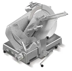
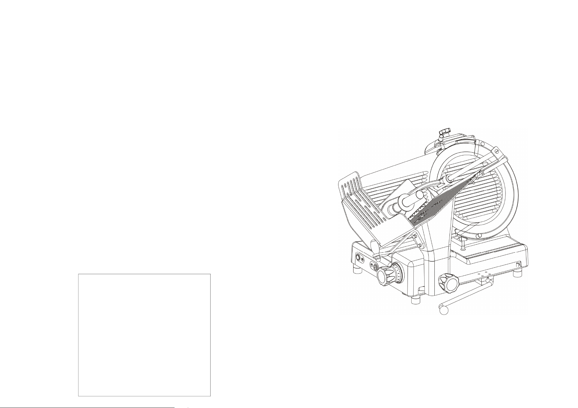
Professional slicer USA
Operating and Maintenance Manual
Code: Edition: 03/2017

2
INTRODUCTION
•
This manual has been re-presented to provide the Client with all the
information on the machine and its safety regulations, and also the use and
maintenance instructions which permit using the machine in the best way and
maintaining its efficiency throughout time.
•
This manual must be kept in its entirety until the machine is disposed of.
•
This manual should be given to personnel in charge of the use and periodic
maintenance of the machine.
INDEX OF CHAPTERS
CHAP. 1 - RECEIVING THE MACHINE
page 4
1.1 - PACKAGE
1.2 - CHECKING THE PACKAGE UPON DELIVERY
CHAP. 2 - INSTALLATION
page 6
2.1 - UNPACKING
2.2 - POSITIONING
2.3 - ELECTRICAL CONNECTION
2.3.1 - Slicer with single-phase motor
2.4 - 115 V. ELECTRICAL DIAGRAM - ‘SIDNEY’ PUSH-BUTTON PANEL
2.4.1 - 115 V. tension selection
2.5 - PRELIMINARY CHECK
CHAP. 3 - INFORMATION ON THE MACHINE
page 9
3.1 - GENERAL PRECAUTIONS
CHAP. 4 -
CONSTRUCTION FEATURES page 11
4.2 - SAFETY DEVICES INSTALLED ON THE MACHINE
4.2.1 - Mechanical safety
4.2.2 - Electrical safety
4.3 - DESCRIPTION OF THE MACHINE
4.4 - OVERALL DIMENSIONS, WEIGHT, FEATURES….
CHAP. 5 - MACHINE USE
page 16
5.1 - OPERATIONAL CHECK
5.2 - LOADING AND CUTTING THE PRODUCT
5.3 - SHARPENING THE BLADE
CHAP. 6 - ROUTINE CLEANING
page 19
6.1 - GENERALITIES
6.2 - CLEANING THE MACHINE
23
CHAP. 8 - DISMANTLING
8.1 - OUT OF SERVICE
If for some reason it is decided to put the machine out of service, make sure that
it cannot be used by anyone: detach or cut the electrical connections.
8.2 - DISPOSAL
Once the machine is put out of service it can be easily disposed of. To correctly
dispose of the slicer, ask any company assigned to such a service carefully
observing the materials used for the various components (see chap. 4 par. 4.1).

22
CHAP. 7 - MAINTENANCE
7.1 - GENERALITIES
Before carrying out any maintenance operations it is necessary to:
a) disconnect the feed plug from the electrical network to completely isolate
machine from the rest of the system.
b) bring the graduated handgrip which regulates the thickness gauge to “0”.
7.2 - BELT
The belt does not need to regulated. Generally after 3/4 years it must be
replaced, in this case call the “SERVICE CENTER”.
7.3 - FEET
The feet could deteriorate in time and lose their elasticity, therefore decreasing
the stability of the machine. Replace them by calling the “SERVICE CENTER”.
7.4 - FEEDING CABLE
Periodically check the state of wear and tear of the cable and call the “SERVICE
CENTER” for its replacement.
7.5 - BLADE
Check that the diameter of the blade, after many sharpenings, has not been
reduced more than 10 mm. compared to the original diameter. For its
replacement call the “SERVICE CENTER”.
7.6 - GRINDERS
Check that the grinders continue to have their abrasive property during the
sharpening. When they are no longer abrasive they must be replaced as to not
damage the blade, therefore call the “SERVICE CENTER”.
7.7 - SLIDING GUIDES LUBRICATION
Occasionally put a few drops of oil (from the tube that is provided) on the round
bar that the trolley slides back and forth on, through the hole (OIL) located on the
side of the graduated handgrip.
7.8 - PUSH-BUTTON PANEL LABEL
The push-button panel label can be marked and/or punctured with time. In such
a case call the “SERVICE CENTER” to replace it.
3
CHAP. 7 - MAINTENANCE
page 22
7.1 - GENERALITIES
7.2 - BELT
7.3 - FEET
7.4 - FEEDING CABLE
7.5 - BLADE
7.6 - GRINDERS
7.7 - SLIDE GUIDES LUBRICATION
7.8 - PUSH-BUTTON PANEL LABEL
CHAP. 8 - DISMANTLING
page 23
8.1 - PUTTING OUT OF SERVICE
8.2 - DISPOSAL
4
CHAP. 1 - RECEIVING THE MACHINE
1.1 - PACKAGE
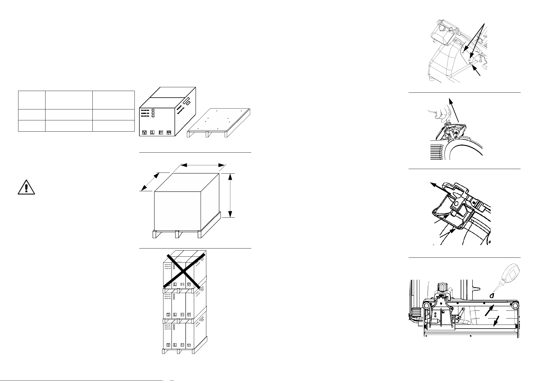
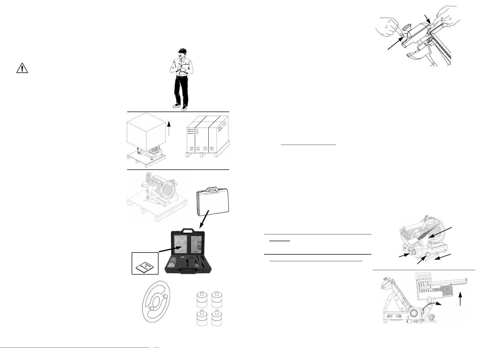
The slicer is shipped in a package which consists of (Fig. n°1): cardboard box,
wooden pallets and protective nylon. They should be disposed of separately and
according to the norms in force in the country of installation.
Dimensions
AxBxC
Gross weight
(Kg)
RFL 330 760x640x700 46
RFL 350 760x640x700 47
Do not place more than one of the
same package on top (Fig. n°3).
WARNING!
B
A
C
Fig. n°1
Fig. n°2
Fig. n°3
21
6.2.4 - Cleaning the sharpener (Fig.
n°51 - 52)
To clean the sharpener it is necessary
to adhere to the following instructions:
1. lift (a) the sharpener up to the top;
2. loosen the knob (1);
3. lift (b) the cup (2) and extract it so
that the knob (1) passes through the
larger opening in the cup (2);
4. rub the grinders with a brush, while
cleaning the other components with
warm water, the equipped detergent
or with neutral detergent (pH 7).
6.2.3 - Cleaning the sliceguard (Fig.
n°50)
To remove the sliceguard simply grasp
the handgrip (1) and pull up so that the
two pins unhook (2), and then extract
the sliceguard.
At this point clean the sliceguard with
warm water, the equipped detergent or
with neutral detergent (pH 7).
Fig. n°50
Fig. n°51
Fig. n°52
6.3 -
SLIDE GUIDES LUBRICATION
The slide guides on the carriage (1-2)
must be lubricated periodically with the
equipped oil (a). (Fig. n°53)
a
1
2
Fig. n°53
2
1
b
1
2
a
n°49 ref.d) on the blade with the two-
knobs(Fig. n°49 ref.e) on the jig,
simply making the blade turn to the
desired position;
6.screw the two knobs (e) without
excessively tightening them.
N.B. The bladeguard must be clea-
ned with warm water, the equipped
detergente or with neutral detergent
(pH 7).
6.2.5 - Once the cleaning operations
are finished, replace the devices in
its original position, doing the
procedures in reverse.
20
pH
Fig. n°46
6.2.2 - Cleaning the blade, the blade-
guard and the ring
WARNING:
a pair of metallic gloves
must be worn while cleaning the bla-
de (1) (Fig. n°47) .and a damp cloth
must be used.
Unscrew the hand grips from the blade
guard (1), (2) and extract the blade
guard (3) using the proper grip to hold it
(Fig. n°47). At this point it is possible to
clean the blade a (Fig. n°48).
To clean the surfaces opposite the
blade and the ring, the blade must be
extracted in the following way:
1.unhook the bladeguard (Fig. n°47);
2.take out the sharpening device (Fig.
n°49 ref.a) and open, by using the
graduated handgrip, the thickness
gauge enough to make the jig (Fig. n°
48 ref.b) stick to the blade;
3.unscrew the three or four screws i
(Fig. n°49 ref.f), depending on the
model, which fasten the blade;
4.rest the jig (b) on the blade, so that
the split in the jig fits in the ring (Fig.
n°49 ref.c);
5.match the axes of the two holes (Fig.
Fig. n°47
Fig. n°48
Fig. n°49
a
d
f
b
e
c
3
2
1
-
bring the graduated handgrip to “0” (1
Fig. n°44);
-
bring the trolley (2) to the end of its
run (a) from the controls side; partially
unscrew the plate lock handgrip (3),
pull the trolley towards the operator;
completely unscrew the plate lock
handgrip and tilting the trolley (b - Fig.
n°45), therefore lift the trolley up (c -
Fig. n°45);
-
having taken off the trolley, the goods
holder plate can be carefully cleaned
with warm water, the equipped
detergent or neutral detergent (pH 7)
Fig. n°46.
5
When the package is received, if there is no
external damage proceed to opening it, ma-
king sure that all material is inside. If the
package upon delivery shows signs of tam-
pering (Fig. n°8), impact or fall, it is
necessary to present the damage to the
carrier, and within 3 days of the delivery da-
te, indicated on
the documents, make a
precise report of the damage. Do not over-
1.2 - CHECKING THE PACKAGE UPON DELIVERY
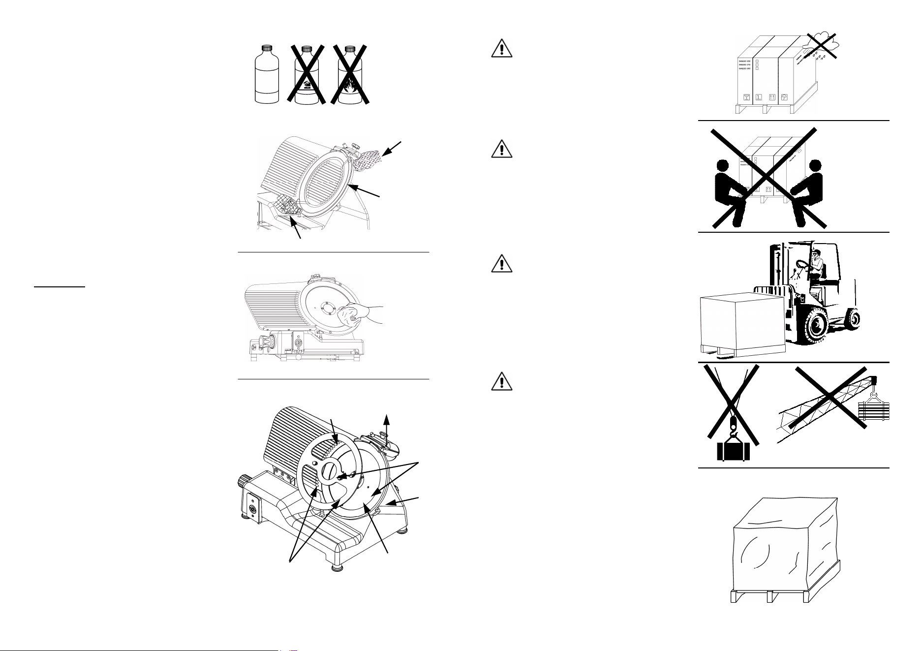
Heavy package. Do not lift manually
unless with help of at least three people
(Fig. n°5).
Move the package only by electrical
trolleys or manually, equipped with
lifting straps (Fig. n°6).
Do not expose the package to humidity
or rain (Fig. n°4).
Since the center of gravity is not in the
middle of the package, moving it su-
spended by chords or similar systems
is not advisable (Fig. n°7).
Fig. n°4
Fig. n°6
Fig. n°5
Fig. n°8
Fig. n°7
6
turn the package!! When transporting it make sure that it is firmly held by the four
corners (keeping it parallel to the floor
).
All operations must be carried out by
specialized personnel (Fig. n°9).
WARNING!
2.1 - UNPACKING
Remove the straps from the package
(Fig. n°10) and lift the cardboard (h).
The package should be:
a) the machine on the pallet (Fig. n°11
detail a);
b) blade extractor (Fig. n°11 detail b);
c) 4 feet (Fig. n°11 detail c);
d) kit case (Fig. n°11 detail d).
e) Instruction booklet (detail e) .
CHAP. 2 - INSTALLATION
Fig. n°9
Fig. n°10
h
a
d
Fig. n°11
e
b
c
19
N.B.: Do not carry on the deburring operation for more than 3/4 sec. to
avoid the damaging bending of the blade edge.
CHAP. 6 - ROUTINE CLEANING
6.1 - GENERALITIES
•
Cleaning the machine must be carried out at least once a day or, if necessary,
more frequently .
•
All the parts of the slicer that come in direct or indirect contact with the food to
be cut must be scrupulously cleaned.
•
The slicer must not be cleaned with water cleaning machines or water jets, but
with the product provided and/or with neutral detergents (pH 7), the sanitizer
concentration shall comply with Section 4-501.114, Manual and Mechanical
Warewashing Equipment, Chemical Sanitization – Temperature, pH, Concen-
tration, and Hardness of the FDA Food Code. The use of any other detergent
is prohibited. Utensils, brushes and whatever else could damage the machine
surface must not be used.
•
If a chemical sanitizer other than chlorine, iodine or quaternary ammonium is
used, it shall be applied in accordante with the EPA-registered label use in-
struction.
•
This machine shall be cleaned and saitized at intervals to comply with National/
state or local health code.
Fig. n°43
3
2
9. once the operation is finished,
replace the sharpening device in its
original position, doing the procedure
in reverse.
Before carrying out any cleaning
operation it is necessary to:
1. disconnect the plug from the electrical
network to completely isolate the
machine from the rest of the system;
2. Bring the graduated handgrip which
regulates the thickness gauge to “0”.
WARNING: Be careful of residual risks
from sharp and/or pointed parts.
6.2 -
CLEANING THE MACHINE
6.2.1 - Cleaning the goods holder plate
The trolley (plate + arm + stem) is
easily tilting (Fig. n° 45) and
transportable (Fig. n°45) or only
(optional) tilting:
Fig. n°45
c
1
a
3
2
Fig. n°44
b
18
5.3 -
SHARPENING THE BLADE
1. disinsert the plug from the outlet and
carefully clean the blade with
denatured alcohol so it is degreased;
2.
lift (a) the sharpener (1) and turn it
180° (b Fig. n°40);
WARNING: Before starting to sharpen the blade, pay attention to RESI-
DUAL RISKS (chapter 4.2.2) concerning the dangers of cutting without ha-
ving followed the instructions listed below.
To sharpen the blade, which needs to be done periodically as soon a decrease
in cutting is noticed, the following directions must be adhered to:
Fig. n°40
Fig. n°41
c
d
3. let it go in a way that the sharpener
(c) fits on the locator pins (d Fig. n°
41);
4. check also that the blade stays be-
tween the two grinders;
1
b
a
5. insert the pin and start the machine,
by pressing the “ON” push-button;
6. press the push-button (2 Fig.n°42),
let the blade rotate in contact with the
grinder for about 30/40 sec. so that a
slight burr forms on the blade edge;
7. press the 2 push-buttons (2 and 3)
contemporaneously for 3/4 sec. and
release them in the same instant
(Fig. n°43);
8. after having completed the sharpe-
ning it is advisable to clean the grin-
ders and the blade (chapter 6.2);
Fig. n°42
2
7
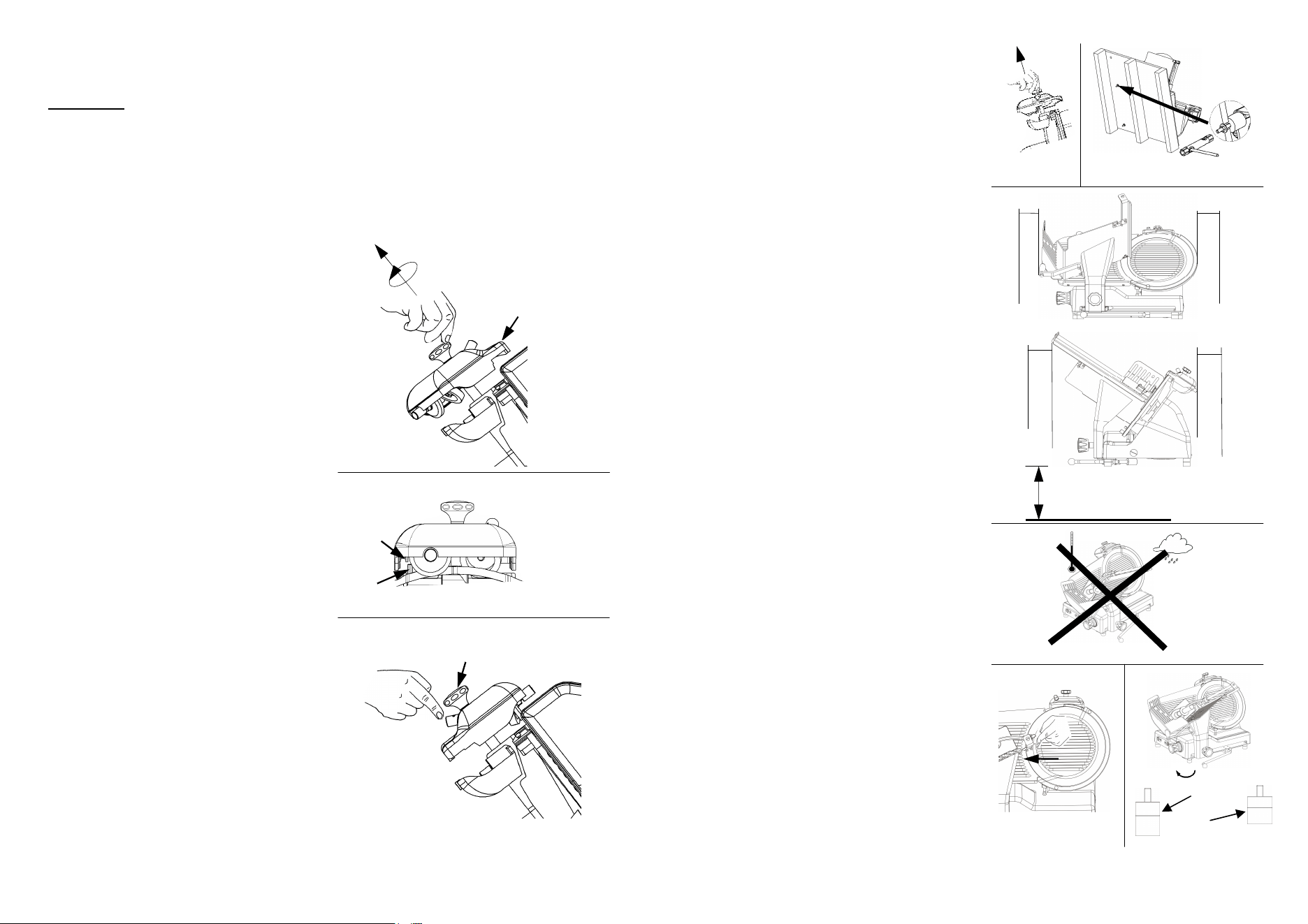
2.2 -
POSITIONING
Position the pallet, with the slicer, on a
flat surface and take off (a) the sharpe-
ner from the slicer (Fig. n°12).
At this point turn the machine on its
side (Fig. n°13) and unscrew, with the
proper wrench provided, the 4 nuts
which fasten the slicer. Remove the 4
washers and unscrew the 4 fastening
tie rods on the wooden pallet. Take off
the pallet and fasten the 4 feet provi-
ded. Finally, put the sharpener in its
place.
Position the slicer in the predestined
place.
The dimensions indicated in Tab. 1-2-3
(according to the model) must be kept
in mind for the plane where the slicer
will be installed, therefore it must be
wide enough, well-levelled, dry, smo-
oth, robust, stable about 80 cm high off
the ground and at least 20 cm from
walls, objects, shelves, etc. (Fig. n°14)
in respect to the space necessary for
its use and safeguarding.
Furthermore the machine must be pla-
ced in an environment with a maximum
humidity of 75%, not salty and with a
temperature between +5°C and +35°C;
in any case in environments which do
not lead to deviations of the above.
Make sure the graduated handgrip is in
posiion “0”.
Check the alignment of the blade-plane
thickness gauge by running a finger
(Fig. n°16) from the blade towards the
thickness gauge plane (never in the op-
posite direction). Unscrew and screw
the foot (1) until the correct alignment is
found (Fig. n°17), then screw the rub-
ber part (2) to fix everything (Fig. n°17).
a
~ 80cm
20cm
Fig. n°12 Fig. n°13
Fig. n°14
Fig. n°15
Fig. n°16 Fig. n°17
20cm
20cm
1
2
20cm
8
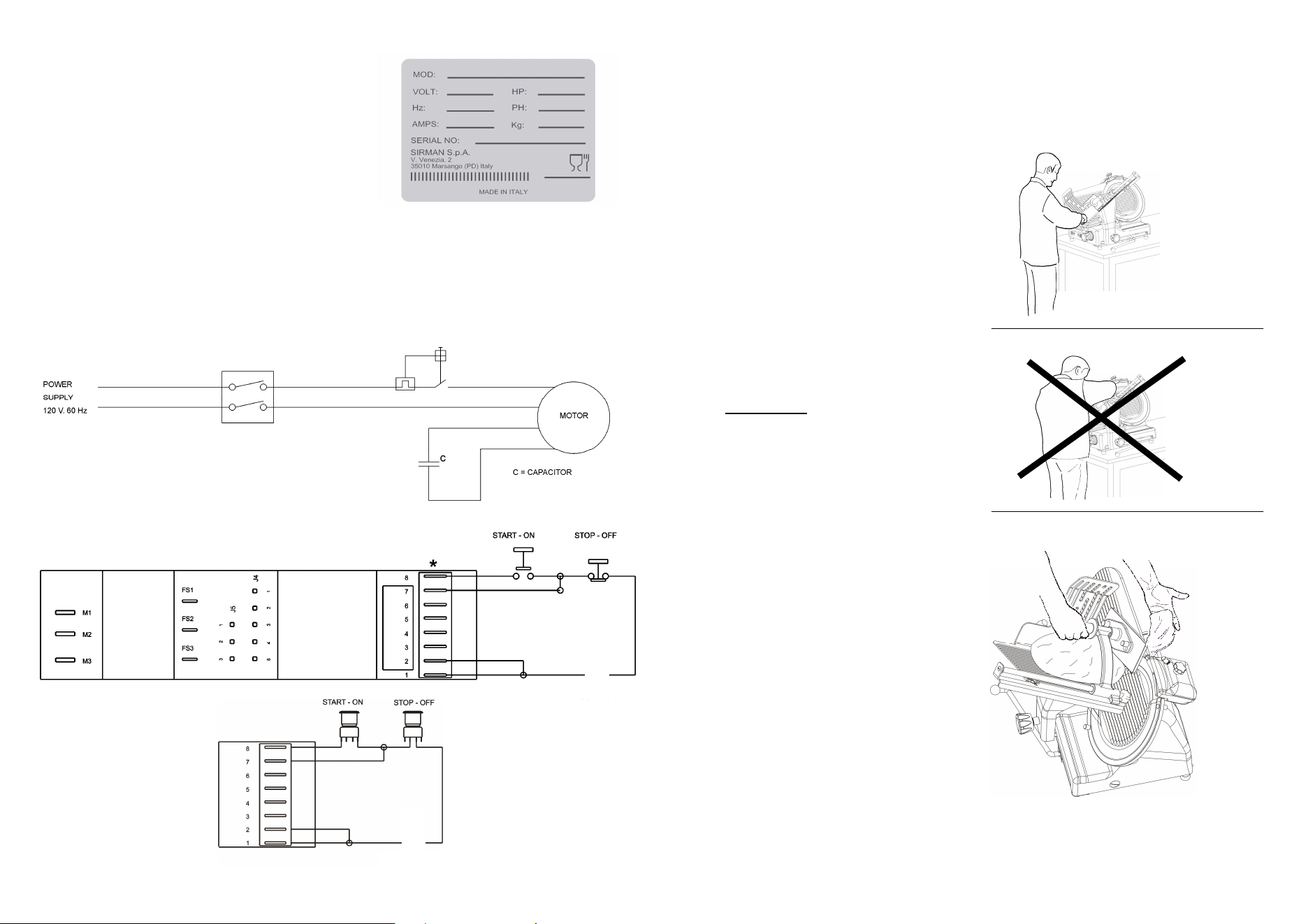
2.3 - ELECTRICAL CONNECTION
Check that the data reported on the
technical-part number plate (Fig. n°18),
the delivery documents and the order,
correspond; contact the supplier for cla-
rification if they do not.
At this point make sure that the system
is standard and that the cable and
grounding system perfectly operate.
2.3.1 - Slicer with single-phase motor
The slicer is equipped with a feeding cable with a cross section area of AWG;
length ≅1.5m and a “UL” plug. Connect the 120 V. - 60 Hz slicer, interposing a
magnetothermic differential switch of 10A, ∆Ι= 0.03A.
Fig. n°18
2.4 - 115 V. ELECTRICAL DIAGRAM , ‘SIDNEY’ PUSH-BUTTON
Fig. n°20
2.4 - 120 V. ELECTRICAL DIAGRAM SWITCH
Fig. n°19
—–
—–
17
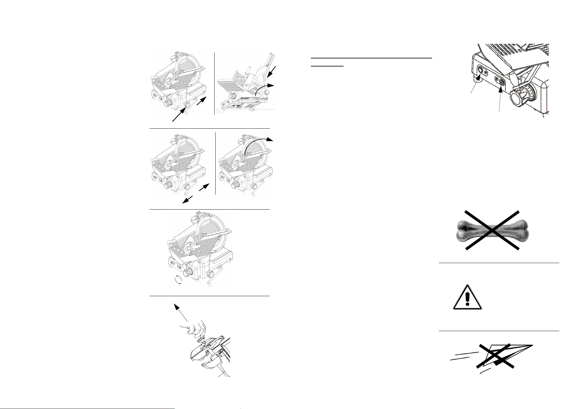
5.2 - LOADING AND CUTTING THE PRODUCT
Adhere to the following procedure:
1. Lift the goods presser, load the go-
ods on the plate, bringing it close to
the thickness gauge, block it with
the proper toothed arm;
2. regulate the desired thickness of the
cut with the graduated handgrip;
3. assume a correct position to avoid
accident: place the right hand on the
goods presser handgrip and, then
the left hand next to the slice guard
to take the cut product (without tou-
ching the blade); the body must be
perpendicular to the work plane (Fig.
n°37).
WARNING: Do not assume
positions which bring body parts
in direct contact with the blade
(ex. Fig. n°38);
4. then push the “ON” push-button;
5. push the carriage (plate + goods
presser arm + stem) gently towards
the blade, without applying excessi-
ve pressure on the product with the
goods presser arm. The goods will
easily enter the blade, and the slice
guided by the proper sliceguard will
detach and fall on the plane (Fig. n°
39);
6. avoid running the slicer when
empty ;
7. at the end of the cutting operation,
stop the machine by putting the
switch in the “OFF” (ARREST)
position and put the graduated han-
dgrip at “0”;
8. Carry out resharpening the blade as
soon as the cut product has a threa-
ded or rough surface, therefore the
cutting effort increases (chapter
5.3).
WARNING: The goods to be cut are loaded on the plate only with the graduated
handgrip at “0” and the motor stopped, being careful with the blade and the
points.
Fig. n°37
Fig. n°38
Fig. n°39
16
CHAP. 5 - MACHINE USE
5.1 - OPERATIONAL CHECK
For the 1° use follow these
instructions:
-
check that installation has been car-
ried out correctly as in chapter 2;
-
check that the plate is well fastened
with the lock handgrip (Fig. n°33
ref.1);
-
bring the carriage tray in the bottom
(a) and check the correct functioning
of the lifting lever (Fig. n°33 ref.2).
-
check the sliding of the plate and that
it is free of obstacles on the work
counter for all of its run (Fig. n°34
ref.b);
-
check that the goods pressing arm
easily rises and lowers so that it is not
impeded in all its movement (Fig. n°
34 ref.c);
Fig. n°33
Fig. n°34
-
check the opening of the thickness
gauge plane by making the numbered
handgrip turn clockwise and counter-
clockwise (Fig. n°35 ref.d);
d
Fig. n°35
-
check that the sharpener is well
fastened to the machine and that it is
easy to extract and free of obstacles
(Fig. n°36 ref.e).
Fig. n°36
e
1
b
c
2
a
9
2.5 - PRELIMINARY CHECK
Before testing make sure the goods
holder plate is well-blocked, after which
test functioning with the following
procedure:
-
Push the “ON” and the “OFF”
(ARREST) (Fig. n°21);
-
Check if the machine does not start
automatically by removing the plug
and reinserting it while the machine is
running.
CHAP. 3 - INFORMATION ON THE MACHINE
3.1 - GENERAL PRECAUTIONS
The general precautions, even though they appear obvious, are fundamental for
the installation, use, maintenance and possible inconveniences with their
respective solutions.
Fig. n°21
“ON”
“OFF”
•
The slicer has been designed to cut
fresh boneless meats and pork pro-
ducts (Fig. n°22). Any other use, in-
cluding cutting vegetables, is conside-
red unappropriate and therefore dan-
gerous.
•
The Manufacturer is not responsible
in the following cases:
⇒
the machine is tampered with by
unauthorized personnel;
⇒
components are substituted with
unoriginal parts;
⇒
the instructions in this manual are
not followed carefully;
⇒
the surfaces of the machine are
treated with inappropriate
products.
•
Keep this manual in a safe place for
future information or consultation (Fig.
n°23).
WARNING!
Fig. n°22
Fig. n°23
10
•
The slicer must only be used by
trained personnel who know the
safety norms contained in this manual
perfectly.
•
In the case of an alteration in
personnel, give time for training.
•
Do not allow the slicer to be used by
children or by untrained people
(Fig. n°24).
•
Before carrying out any cleaning or-
maintenance operation, disconnect
the machine plug from the electrical
network.
•
When carrying out routine mainte-
nance or cleaning of the slicer (and
therefore the guards are removed),
carefully evaluate the residual risks .
•
During maintenance or cleaning stay
concentrated on the operations.
•
Do not use corrosive or flammable
substances to clean the slicer (Fig. n°
25); only use the product provided
•
To clean the slicer carefully follow the
instructions in the chapter: “Routine
cleaning”.
•
Do not wash the slicer in a dishwa-
sher (Fig. n°26) or with water jets, do
not immerge it in water or in other li-
quids.
ATTENTION!
•
Do not leave the slicer exposed to
damaging agents: sun, rain, sprays,
humidity, ice (Fig. n°27).
Fig. n°25
Fig. n°26
Fig. n°27
Fig. n°24
15
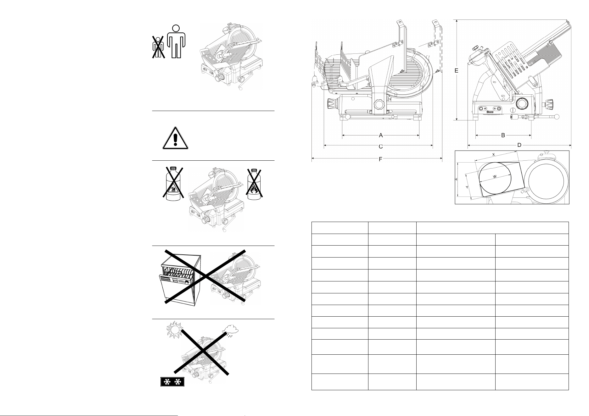
TAB. n°1 -
DIMENSION MEASUREMENTS AND TECHNICAL FEATURES
Fig. n°32
Model U.m.
Blade diameter mm 330 350
Motor Watt/Hp 275/0,37
370/0,5
Cut thickness mm 23
23
Run of carriage mm 355
355
Hopper mm 350x330
350x330
A x B mm 513x340 513x340
C x D x E mm 690x560x475 690x560x475
F x D mm 840x560 840x560
X Y H W mm 307 205 260 240 307 205 260 240
Net weight Kg 37 38
Power source Mn 120V / 60 Hz
120V / 60Hz
Noise level dB
≤ 60 ≤ 60
mod. 330-350

14
Even though the professional slicers are equipped with the standard mea-sures
for electrical and mechanical protection (both while operating and during clea-
ning and maintenance), RESIDUAL RISKS which cannot be completely elimina-
ted in any case exist, highlighted in this manual under the form of WARNING.
They concern the danger of cutting, bruising and other caused by the blade or by
other machine parts.
4.3 - DESCRIPTION OF THE MACHINE
Professional slicers have been designed and made by our company with the pre-
cise purpose of cutting food products (like lunch meat and meats) and they gua-
rantee:
- maximum safety in use, cleaning and maintenance;
- maximum hygiene, thanks to a meticulous selection of materials that come in
contact with the food products, and with the elimination of the edges in the
parts of the slicer that come into contact with the product, in a way that it can
be easily and totally cleaned not to mention easily disassembled;
- maximum cutting precision thanks to the cam mechanism;
- all components are robust and stable;
- maximum silence thanks to the belt transmissions;
- very easy to handle.
4.4 - OVERALL DIMENSIONS, WEIGHT, FEATURES ...
WARNING:
The electrical features of the machine are shown on a plate on the back of the
machine.
11
•
Do not pull the slicer or the feeding
cable (Fig. n°28) to unplug it.
•
Regularly check the state of the fee-
ding cable; a worn out cable or in any
case not intact represents a serious
electrical danger.
•
If the machine remains unused for
long periods of time, before using it
again have it checked by a “Service
Center”.
•
If the slicer should show signs of
malfunctioning it is advisable to turn it
off and to not use it, to not directly in-
tervene for repairs, and to contact the
“Service Center”, shown on the back of this manual.
•
Do not leave the slicer uselessly plugged in. Unplug the machine when it is not
being used.
•
Even if safety devices are installed on dangerous points of the machine, avoid
placing hands near the blade and other moving parts.
•
Never cut the product, by now finished, without the aid of the goods
pressing arm.
•
Do not assume positions that bring body parts in direct contact with the
blade.
CHAP. 4 - GETTING TO KNOW THE SLICER
4.1 - CONSTRUCTION FEATURES
The slicer is made of an anodized alluminum alloy (Peraluman AlMg3). It
guarantees contact with food-stuffs (hygienic) and is resistant to acids and salts
apart being highly resistant to oxidation.
The blade is in 100 Cr6 rectified, chromium-plated and hardened steel assuring a
precise and net cut of the product even after being sharpened. The majority of
the other components present are in:
-
ABS:
-
AISI 430 or 304 steel.
Fig. n°28
12
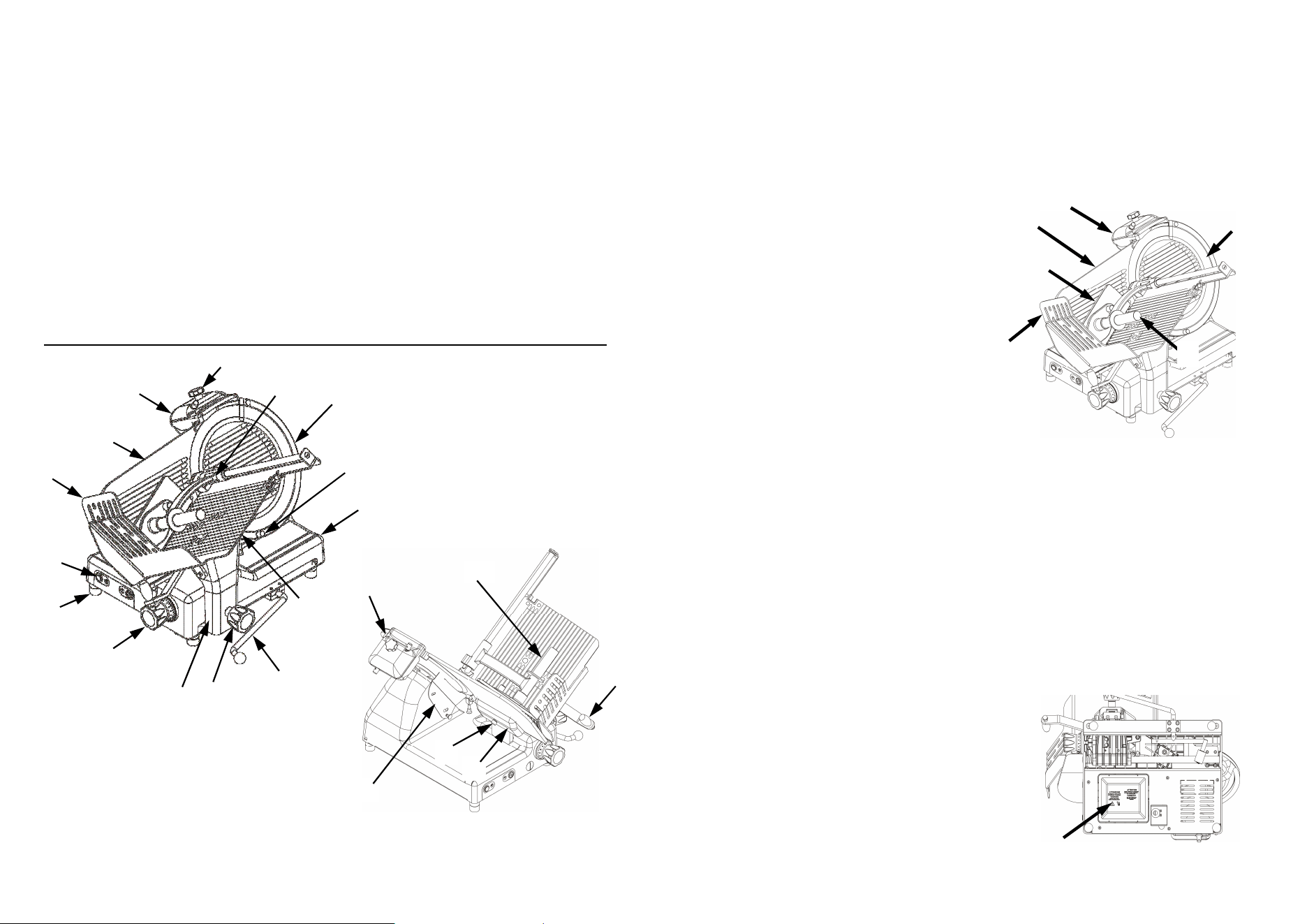
LEGEND:
1 Sharpener handgrip 12 Base
2 Sharpener 13 Extractable pin
3 Thickness gauge plane 14 Bladeguard
4 Handguard 15 Goods presser
5 Push-button panel 16 Goods presser handgrip
6 Foot 17 Bladeguard tie rod knob
7 Graduated handgrip 18 Sliceguard
8 Stem 19 Thickness gauge plane sharpener handgrip
9 Stem knob 20 Thickness gauge plane sharpener
10 Lifting lever 21 Knob movement carriage tray
11 Goods holder plate
5
7
8
9
10
11
12
13
6
4
3
2
1
15
14
Fig. n°29
20
19
18
17
16
21
13
4.2 - SAFETY DEVICES INSTALLED ON THE MACHINE
4.2.1 - Mechanical safety
As far as mechanical safety is concerned, the slicer described in this manual
responds to:
-
UL 763 machine directives;
-
the CSA 22.2 norm.
4.2.2 - Electrical safety
As far as electrical safety is concerned, the slicer described in this manual re-
sponds to:
-
the UL 763 norms;
-
the CSA 22.2 norms.
The slicer is therefore provided with:
-
As far as hygienic safety is concerned
The slicer described in this manual re-
sponds to NSF Standard 51.
- A relay in the control circuit, that re-
quires the machine to start up again
in case of an accidental loss of electri-
city (Fig. n°31).
Safety is made possible by the:
- Thickness gauge plane
(Fig. n°30 ref. n°1);
- Ring
(Fig. n°30 ref. n°2);
- sharpener
(Fig. n°30 ref. n°3);
- Goods presser
(Fig. n°30 ref. n°4);
- Goods presser handgrip
(Fig. n°30 ref. n°5);
- handguard
(Fig. n°30 ref. n°6);
- Trolley transported only when thick-
ness gauge plane is at “0”, at the end
of the run and towards operator side.
Relay in
circuit
Fig. n°31
6
4
1
3
2
5
Fig. n°30