28
CHAP. 8 - DISPOSAL OF THE MACHINE
8.1 - DISINSTALLATION
If it has been decided to disinstall the machine for some reason, ensure that the
machine is unusable by anyone: detach and cut electrical connections.
SERVICE CENTRE
AUTHORISED DEALER
1
Professional Hand-Held Mixer
W 20-28-36 / VT
W 43-55-75 / VT
Regular
Stabilized speed variator
Instructions for use and maintenance
Ver. 001 - ed. 06/2021

2
INTRODUCTION
•
This manual has been written to supply the Customer with all the information
on the machine and the related safety rules, as well as the instructions for the
receipt of the machine itself, cleaning, maintenance and disposal that allow to
use and maintain the means keeping its efficiency intact throughout the time.
•
This manual it to be kept till the disposal of the machine.
•
This manual is to be kept at disposal of members of staff that have been
appointed to operate the machine and to carry out maintenance tasks.
TABLE OF CONTENTS
CHAP. 1 - RECEIPT OF THE MACHINE page 4
1.1 - PACKAGING
1.2 - BOX CHECK UPON RECEIPT
CHAP. 2 - INSTALLATION page 6
2.1 - UNWRAPPING
2.2 - PLACEMENT
2.3 - ELECTRICAL CONNECTION
2.4 - ELECTRICAL DIAGRAM
CHAP. 3 - MACHINE’S INFORMATION page 10
3.1 - GENERAL PRECAUTIONS
CHAP. 4 - GETTING ACQUAINTED WITH THE MACHINE page 13
4.1 - MACHINE’S DESCRIPTION
4.2 - IN-BUILT FEATURES
4.3 - IN-BUILT SAFETY DEVICES
4.3.1 - Mechanical safety devices
4.3.2 - Electrical safety devices
4.4 - OVERALL DIMENSIONS, WEIGHT, FEATURES
CHAP. 5 - USE OF THE MACHINE page 19
5.1 - MOUNTING THE ACCESSORIES
5.2 - PREPARATORY CHECK
5.3 - USE’S FIELDS
5.4 - MACHINE’S USE
CHAP. 6 - REGULAR CLEANING page 23
6.1 - GENERAL INFORMATION
6.2 - EXTRA CLEANING
6.2.1 - GENERAL INFORMATION
27
CHAP. 7 - MAINTENANCE
7.1 - GENERAL INFORMATION
Before carrying out any maintenance task, it is recommended to:
unplug the feeding cable from the net to insulate the machine from the rest of the
plant completely.
7.2 - DIPPING OF ACCIDENTAL FALL OF THE MACHINE
In case of immersion or accidental fall of any accessory or the machine itself, do
not use it and contact CUSTOMER SERVICE.
7.3 - SHAFT AND WHIP FIXING
Check that the shaft and the whip are firmly and solidly fixed to the engine’s
body. If this is not the case, please contact CUSTOMER SERVICE.
7.4 - FEEDING CABLE
Periodically, check the state of wear of the feeding cable and in case, contact
CUSTOMER SERVICE.
7.5 - COMMANDS LINING
Periodically, check the state of wear of the rubber commands lining and in case
of wear contact CUSTOMER SERVICE.
7.6 - BLADE
Check the sharpness of the shaft’s blades to replace them, please contact
CUSTOMER SERVICE.
7.7 - WHIPS
Check that the whips keep their original conformation and that they do not
detach easily from the whip’s body. If this is not the case, please contact
CUSTOMER SERVICE.
7.8 - GASKETS - SEALING RINGS
Periodically check the sealing gaskets, once the knife-holding base is
disassembled (Fig. 64)
If these show wear, contact CUSTOMER SERVICE.
26
it is recommended to use protective gloves and to be extremely careful all the
time.
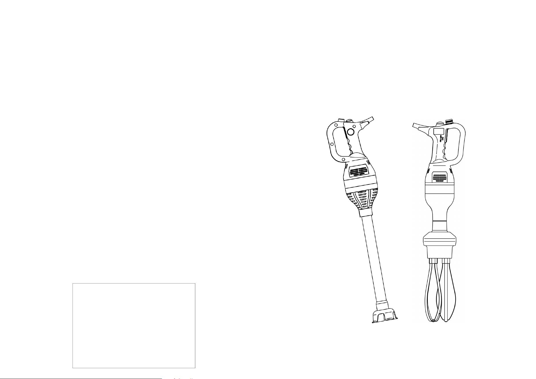
Disassembly of the shaft (Fig. 64)
1. Detach the shaft from the engine’s body and position it on a surface with the
knives on the right side.
2. Predispose the tools (a-b-c), grip the tool (c) with the left hand and insert it in
the dragging device inside the shaft
3. ATTENTION: Using a key (3), unscrew anticlockwise till the blade group is
removed.
4. Grip the tool with the right hand (a) and insert it in the lower support matching
the reference. Unscrew everything clockwise till removal of the lower support.
Pay attention not to lose the sealing gasket (O-ring) from the lower support.
5. Remove the inner shaft from the main shaft pushing it towards the tool (c).
6. Proceed to clean the single pieces with a dump cloth and some dish deter-
gent, keeping in mind that the bearings must not come into contact with liq-
uids.
7. In case of encrustation, insist with the cloth. Do not use abrasives, pointy or
sharp tools.
8. Re-assemble everything the opposite way. ATTENTION: fix firmly the knife or
this could detach itself during the operating stage.
Check the state of the gaskets 1 and 2. In any other case, call Customer Service
for supplies and replacements.
1
(b)
2
4
(c)
(a)
3
Fig. n°64
Gasket 1-2
O-ring gasket
3
CHAP. 7 - MAINTENANCE page 27
7.1 - GENERAL INFORMATION
7.2 - DIPPING OF ACCIDENTAL FALL OF THE MACHINE
7.3 - SHAFT AND WHIP FIXING
7.4 - FEEDING CABLE
7.5 - COMMANDS LINING
7.6 - BLADE
7.7 - WHIPS
7.8 - GASKETS – SEALING RINGS
CHAP. 8 - DISPOSING OF THE MACHINE page 28
8.1 - DISINSTALLATION
4
CHAP. 1 - RECEIPT OF THE MACHINE
1.1 - PACKAGING
The box inside which the dipping blender is freighted, includes an individual wrapping for
each component (Fig. 1):
• engine’s body
• operating shafts (if ordered)
• whip (if ordered)
• transportation’s suitcase (if ordered)
• wall bearing (if ordered)
• kettle bearing (if ordered)
• (Fig. 1): cartoon box, polystyrene inserts, nylon, etc. will have to be disposed of sepa-
rately as per the enforcing norms of the country of installation.
Fig. n°1
Fig. n°2
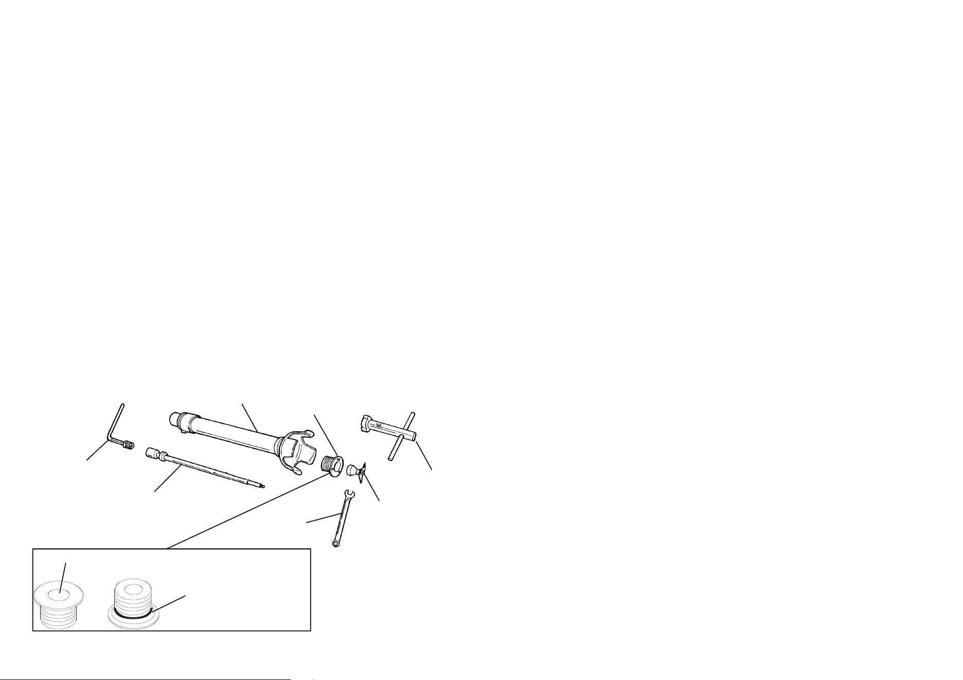
ATTENTION!
Superimpose up to a maximum of five
boxes of the same type (Fig. 2).
It is recommended to keep the box at least
throughout the time of warranty to facilitate
transportation in case of repairs, etc.
A
B
C
AxBxC
mm
Peso lordo
Kg
W 43
300x570x180 3
W 55
300x570x180 3,7
W 75
300x570x180 4,5
Shaft 35
230x490x150 1,5
Shaft 45
230x590x150 2
Whip
210x520x250 2,5
Suitcase
410x600x190 -
W 20
330x440x150 3
W 28
330x440x150 3,2
W 36
330x440x150 3,5
Shaft 25
210x320x220 1
Shaft 35
230x490x150 1,5
Whip
210x520x250 2
25
Fig. n°61
Fig. n°63
to ease the drainage of residual liq-
uid (Fig. 58).
8) Hence place the assembled whip on
the special wall bearing (Fig. 58).
ENGINE’S BODY:
1. unplug the feeding cable from the
net to insulate the machine from the
electrical feeding completely (Fig.
61)
2. Remove possible product splashes
that deposited on the machine’s
body with a wet sponge and dry im-
mediately with a cloth.
3. Check that no residual from the
work nor liquid did not enter the
cone fixing the tools and in such
case remove them with a cloth.
Reuse the blender to another operation
or:
4. Position the engine’s body on the
special wall bearing.
6.2 - EXTRA CLEANING
6.2.1 - GENERAL INFORMATION (Fig.
63)
•
Such operation is an exclusive re-
quirement of this machine.
•
This operation is to be carried out
only in case of poor cleaning tasks
executed by previous operators or in
case unpleasant smells, internal en-
crustations, etc. can be perceived.
•
This operation is quite delicate and
particular even if simple and could
compromise the functioning of the
machine. Therefore, it is recom-
mended to have it carried out only
by responsible and expert members
of staff.
ATTENTION: this operation exposes
the operator to risks due to the manipu-
lation of knives and sharp parts. Hence,
Fig. n°60
Fig. n°62
24
eration till a complete and thor-
ough rinse is guarantied.
5) WARNING: after disconnecting
the machine from the power outlet,
use a non-abrasive wet sponge to
clean the external parts of the
shaft with hot water and, if neces-
sary, the previously used deter-
gent (Fig. 57).
6) WARNING: disconnect the ma-
chine from the power outlet, check
the outcome of the operation and,
if necessary, repeat it from point
(2) or intervene manually on the
parts that are still dirty. The knives
area could provoke wounds to the
hands (Fig. 56). So, please pay
the maximum attention.
7) Reuse the tool for another opera-
tion or:
8) Dry the tool with a cloth and posi-
tion it vertically for 1 or 2 hours to
ease the drainage of residual liquid
(Fig. 57).
9) Hence place the shaft on the spe-
cial wall bearing (Fig. 58).
WHIP (Fig. 59)
Proceed as described for the shafts
till point 5.
6) disassemble the whip from the
whip’s body and check the com-
plete cleaning.
Intervene manually on the parts
that are still dirty, paying attention
to the internal area of the whip’s
body (Fig. 60)
ATTENTION: Whips can be dan-
gerous when handles with bare or
wet hands. Wear protective gloves
and pay maximum attention any-
way.
Reuse the tool for another opera-
tion assembling the whips to the
whip’s engine or:
7) Dry the whip’s body with a cloth
position it vertically for 1 or 2 hours
(1) (2)
(3) (4)
(5)
ATTENTION!
Fig. n°56
Fig. n°59
Fig. n°58
Fig. n°57
a)
b)
5
Once the item has been received, pro-
ceed to the opening and check that all
the material is inside if the box does not
show external damages. While if the
box or the contents show signs of mis-
using (Fig. 6), knocks, fall or ruptures, it
is necessary to inform the freight for-
warder of the damage by writing a de-
tailed report about the possible dam-
ages suffered within three days of the
delivery date. Generally, complaints
that are not communicated immediately
are not taken into consideration by the
freight forwarder.
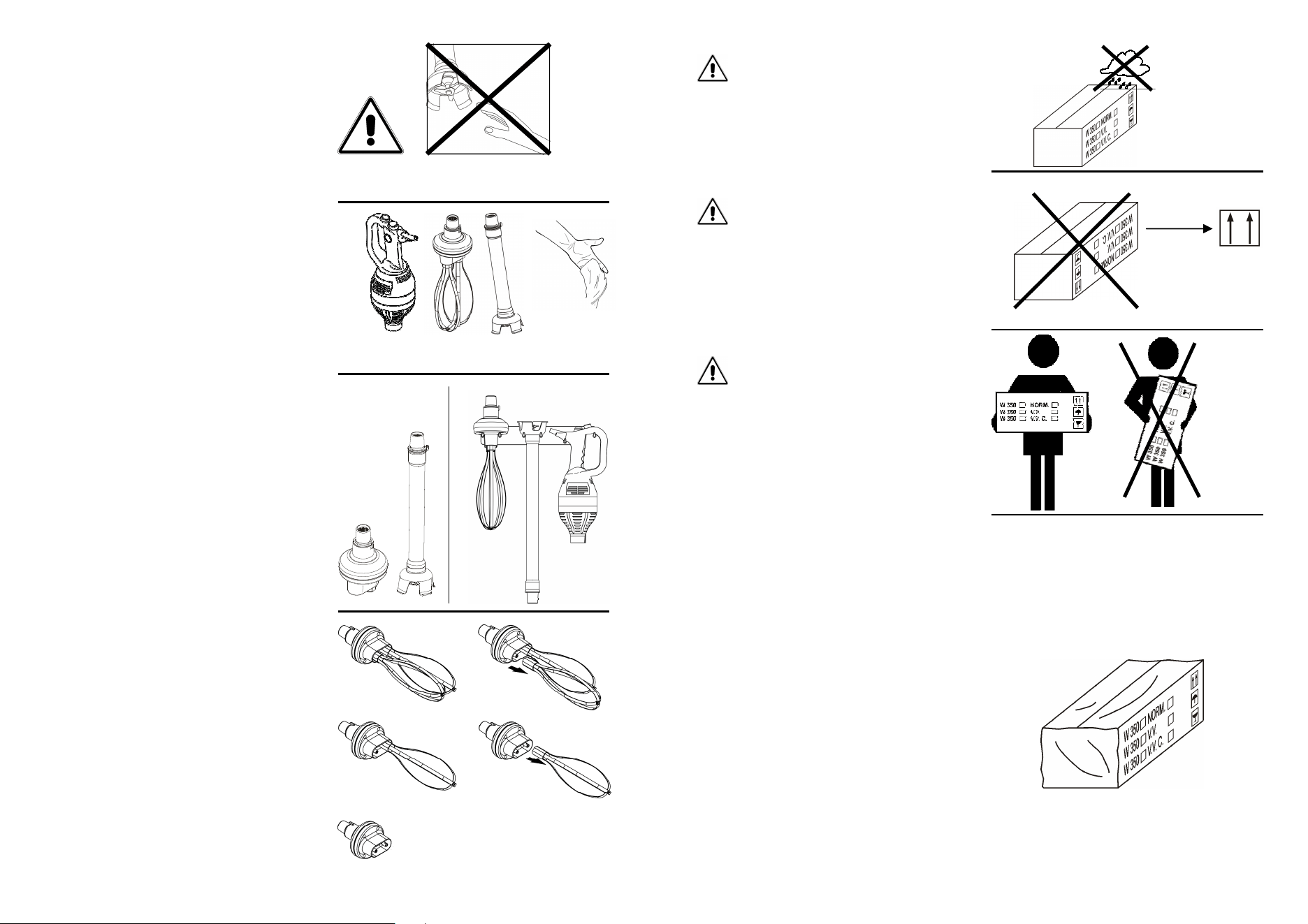
1.2 - BOX CHECK UPON RECEIPT
Do not overturn the box (Fig. 4).
Please ensure that the box is held
firmly at the far ends of its longest
sides, while carrying it and keep the
box itself parallel to the floor (Fig. 5).
Do not leave the box exposed to hu-
midity and rain (Fig. 3).
Fig. n°3
Fig. n°5
Fig. n°4
Fig. n°6
6
All the tasks must be carried out by
trained members of staff (Fig. 7).
ATTENTION!
2.1 - UNWRAPPING
Ensure that the box is not upturned by
checking the direction of the external
writings (Fig. 8)
The contents include:
THE ENGINE’S BODY
a) cartoon wrapping
b) polystyrene inserts
c) the machine’s body
d) the instructions manual
Remove the adhesive tape fixing the
upper flaps of the box and lift the
machine’s body matching the protecting
inserts.
OPERATING SHAFT
The contents include (Fig. 9):
a) cartoon wrapping
b) polystyrene inserts
c) the operating shaft
d) dismounting accessories
Remove the adhesive tape fixing the
upper flaps of the box and lift the shaft
matching the protecting inserts.
OPERATING WHIP
The contents include (Fig. 9):
a) cartoon wrapping
b) polystyrene inserts
c) the operating whip
d) dismounting accessories
Remove the adhesive tape fixing the
upper flaps of the box and lift the whip
matching the protecting inserts.
SUITCASE
If the accessory suitcase has been
ordered, the machine and its related
CHAP. 2 - INSTALLATION
Fig. n°7
a-b)
c)
d)
a-b)
c)
d)
a-b)
c)
Fig. n°8
Fig. n°9
Fig. n°10
23
Fig. n°52
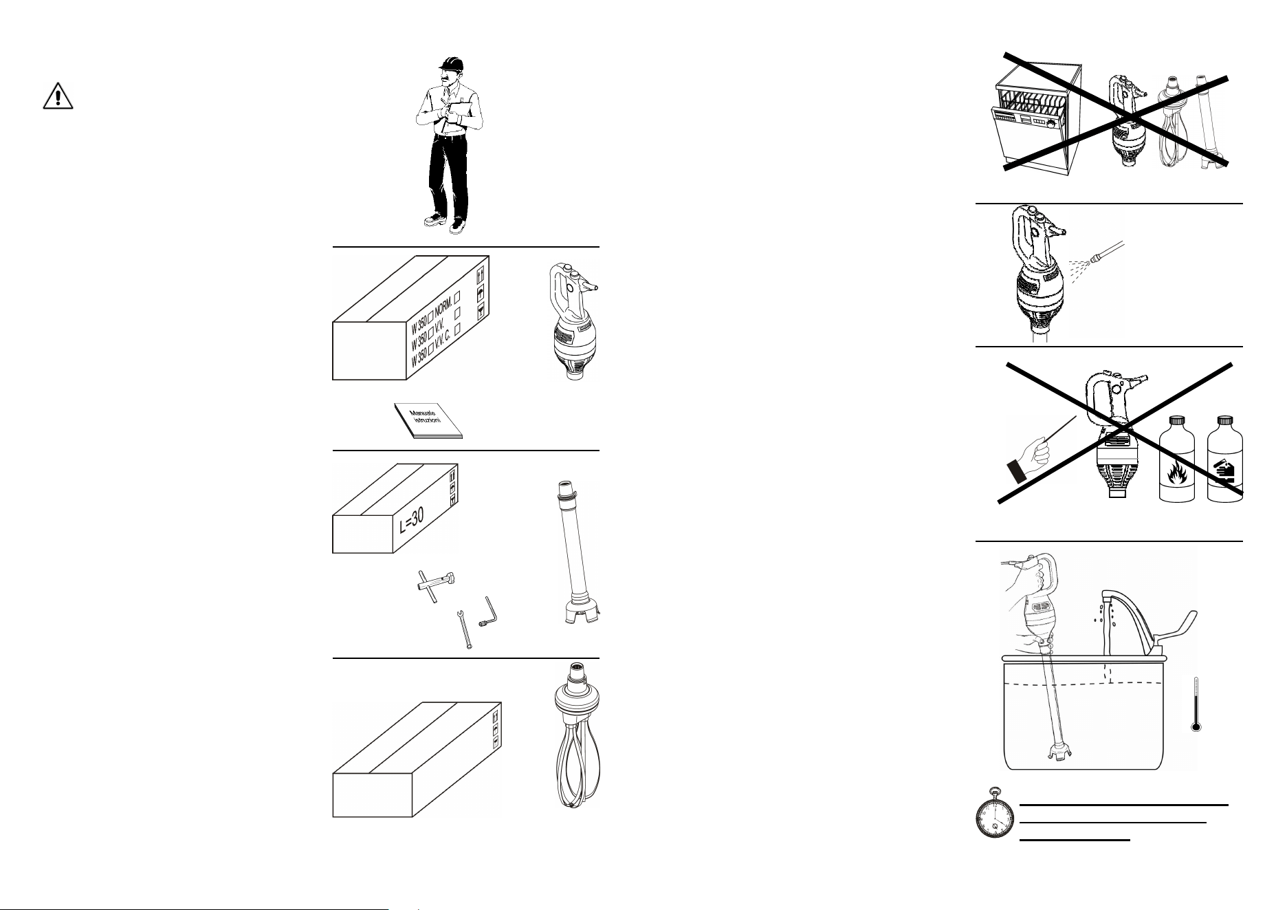
6.1 - GENERAL INFORMATION
•
The cleaning of the machine is an
operation to be done absolutely at
the end of every working cycle.
•
Immediate cleaning, can save a lot
of time, guaranties hygiene and
maintenance of the machine.
•
The cleaning must be scrupulously
detailed in all the parts that come
into direct or indirect contact with
food.
•
The dipping blender must not be
cleaned with water cleaners or water
jets (Fig. 53), and/or with acid or
corrosive detergents that can ruin
the surface (Fig. 54)
•
Tools and brushes or else must not
be used as they might damage the
machine (Fig. 54)
•
Check that the vent’s opening are
not obstructed by dust, dirt or else
periodically. In case these are ob-
structed call the CUSTOMER CEN-
TRE.
ATTENTION: do not use air jets or
else that could provoke dirt’s infiltra-
tions inside the machine (Fig. 53)
For a correct cleaning, it is necessary:
SHAFT (Fig. 55)
1) Get a container sufficiently high to
immerge the shaft to the maximum
level allowed
2) Fill it with hot water 50-60º C and
add dish detergent according to the
need
3) Let the machine operate for 20 sec-
onds simulating the normal produc-
tive process.
4) Empty the container, rinse it and fill
it with warm water. Let the machine
operate again for some more 10-15
seconds, if necessary repeat the op-
Fig. n°53
Fig. n°54
Fig. n°55
Let the dipping blender work
for 20 seconds during the
cleaning stage.
CHAP. 6 - REGULAR CLEANING
22
Switch the machine (please see para-
graph 5.2) and move the shaft and the
whip towards the inner part of the con-
tainer with slow but regular revolving
movements.
It is recommended not to touch the
container’s walls with the whips.
As for the shaft, alternate the revolu-
tion even in the movements from the
top to the bottom to ease the entry of
the products to be whisk in the operat-
ing bell (Fig. 48).
Work till the desired consistency is ob-
tained, once finished using it, switch
the machine off.
ATTENTION: Do not use the machine
in free air and to avoid any risk of
physical or mechanical damage, never
extract the tool from the product while
still rotating (Fig. 49).
ATTENTION: as a result of the centri-
fuge effect, the liquid tends to rotate
and to higher its level closer to the bor-
der of the container, when the blender
is functioning, hence never fill the con-
tainer over 2/3 of its capacity (Fig. 48).
Never carry out work cycles for over 10
minutes and keep the blender switched
off anyway for at least 10 minutes be-
tween a work cycle and the next (Fig.
51).
At the end of the working cycle, re-
move the machine from the working
container and proceed immediately to
the cleaning of the tool (see chapter 6
Regular cleaning).
Never leave the machine unattended
inside the container.
Fig. n°48
Fig. n°49
Fig. n°50
Working cycles:
10 minutes ON – 10 minutes OFF
Fig. n°51
7
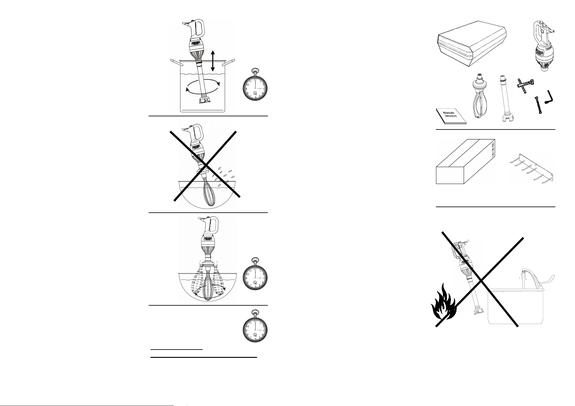
2.2 - PLACEMENT
The machine and its related accesso-
ries must be kept in a dry environ-
ment, far away from heat, humidity,
splashes, dust and anything else that
might damage the dipping blender
and its accessories (Fig. 13).
The machine and its related accesso-
ries after having been used must be
placed on the special wall support
(Fig. 14 A).
In case the accessories are unused
for a long time, they might be stored
in other places as long as these latter
respect the above-mentioned require-
ments and that they guarantee good
conservation of the accessories them-
selves (for instance, drawers that can
bump the components one against
the other or cause them to fall must
be avoided).
The conditions will be the same even
if no wall bearing has been ordered.
Never position the dipping blender
Fig. n°13
accessories will be inside the suitcase
itself.
The contents include (Fig. 11):
a) suitcase with punched protections
(to be stored for future storing and
transportation)
b) the machine’s body
c) the operating shaft (if ordered),
with related accessories for the
demounting
d) the whip (if ordered)
e) the instructions manual
Remove the adhesive tape fixing the
upper flaps of the box and lift the
suitcase.
WALL BEARING (Fig. 12)
It will be supplied in a separate
cartoon box KETTLE BEARING.
Fig. n°11
a) b)
c)
d)
e)
Fig. n°12
8
Check that the data reported on the
register-technical plate (Fig. 15) of the
delivery documents match the
delivery documents, if not please
contact the supplier to have an
explanation.
Fig. n°15
and the accessories inside the suit-
case unless they are perfectly dry.
Fixing the wall bearing (Fig. 14):
The wall where the bearing is to be
fixed must be stable, solid and must
support he weight of the machine and
its related accessories.
Fix the wall bearing by means of pres-
sure screws with tassel of minimum
8mm diameter.
Position the wall bearing to a distance
from the shelves and/or tables which
is sufficient to contain the accesso-
ries.
Position the wall bearing as per the
instructions of chapter 2.2.
Positioning on the wall bearing
(Fig. 14A)
Hook the engine’s body on the two
right supports (of the wall bearing)
with the handle towards right. The
highest support inside the handle and
the other outside beneath the entry of
the feeding cable.
Shaft and whip can be hooked on ei-
ther the other two spaces. The shaft
is to be kept with the bell turned up-
wards, while the whip is to be kept as
if operating.
Check that the bearings are always
solid and parallel or the correct sup-
port of the machine might be compro-
mised.
Fig. n°14A
1
7
8
m
m
1
7
8
m
m
600 mm
Fig. n°14
2.3 - ELECTRICAL CONNECTION
21
5.4 - MACHINE’S USE
ATTENTION:
-
Check that the machine is perfectly
dry and that there is no dirt or humid-
ity from previous uses or washes
(Fig. 43).
-
Check that the shaft or the whip have
not residual encrustations from previ-
ous uses.
-
Before using it, ensure that the shaft
and the whip are fixed to the engine’s
body properly (Fig. 44).
-
Check that in the previous uses the
components or protections have not
been removed.
-
Check the state of the feeding cable
that could have been worn out by the
different knives and tools in the
kitchen. In this case, please contact
CUSTOMER SERVICE immediately.
There are three shafts of different length.
If available, always use the shaft whose
length prevents the immersion of the en-
gine of the product.
Assemble the tools as per chapter 5.
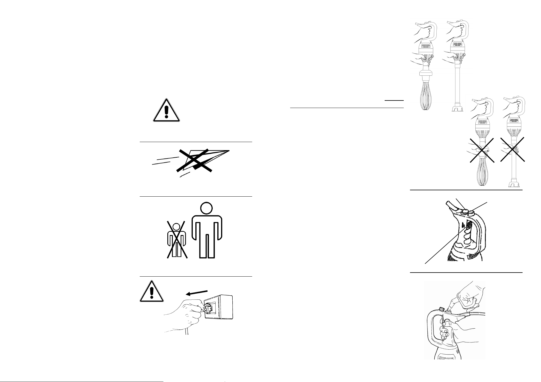
Grip the dipping blender by the handle
with one hand and grip the lowest part
above the maximum level (marked on
the shaft Fig. 45) with the other one.
Never grip the engine’s body in a way to
obstruct the vent’s opening (Fig. 46).
Posture correctly and comfortably in or-
der to work safely and easily.
It is FOR-
BIDDEN to use the immersion blender
with pots placed on burners, heating
plates or on excessively high worktops
(Fig. 47).
Insert the dipping blender with the tool
slightly inclined to the maximum height
marked on the working shaft. As for the
whip, the product must always remain at
2-3 cm from the whip’s body (Fig. 45).
cm 3
Asta
Frusta
Fig. n°44
Fig. n°46
Fig. n°45
Fig. n°47
Fig. n°43
MAX
20
5.3 - USE’S FIELDS
The dipping blender has been designed
to blend, emulsify and whip fruit, vege-
tables, meat, food in general.
The dipping blender has not been de-
signed to work chemicals, sewages,
glues and anything that is not strictly
food.
Even if designed to blend also hot products,
it is recommended to operate with products
at a temperature below 70 degrees C. al-
ways for a short lapse of time (maximum 10
minutes). Followed by a pause of at least 10
minutes.
Do not leave the shaft immersed in food.
Blending:
Use of the shaft (Fig. 41)
Fruit, vegetables, meat, food in general
as long as mixed in some liquid solu-
tion.
Food pieces must have maximum di-
mensions of a nut (3x3x3 cm cubes as
long as without bones or stones and as
long as they are not too hard and con-
sistent).
Whipping, emulsifying:
Use the whip (Fig. 42)
Eggs, milk, etc. can be used to obtain
creamy substances, mousses, cream at
temperatures below 25°C as long as
they do not have or they do not reach
by the end of the operation consisten-
cies that can be compared to other
dough. For the latter the dipping
blender is not suitable.
Fig. n°41
Fig. n°42
9
Fig. n°16
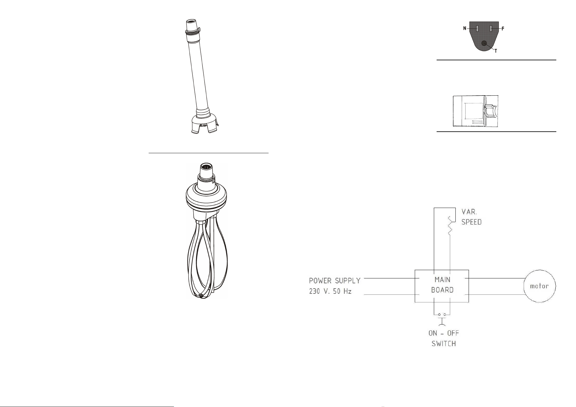
2.4 - ELECTRICAL DIAGRAM – SINGLE-PHASE 120V. (Fig. n°18
)
Fig. n°17
At this point, make sure that
the
electric plant of the building is
according to law.
The dipping blender is supplied with a
feeding cable 3x18AWG, length >
1,6m and a NEMA 5-15P plug (Fig.
16).
The machine is not foreseen to be
ground mass as it is supplied with
double isolation.
Link the dipping blender 120 V. – 60
Hz, interposing a differential (safety
device, Fig. 17) - 10A ΔΙ = 0.03A-
magnetothermic switch.
Fig. n°18
10
CHAP. 3 - MACHINE’S INFORMATION
•
The producer has no responsibility
in the following cases:
The machine has been tampered
by non-authorised members of
staff
Some components have been
replaced with non-original ones
The instructions of this manual
have not been followed carefully
•
Keep this manual with care for fu-
ture reference (Fig. 19)
•
The dipping blender must be used
only by trained members of staff,
who must know the safety rules
contained in this manual perfectly.
•
In case of staff turn-over, please
proceed to train the new members
of staff in timely fashion
•
Do not allow children, incompe-
tents or untrained members of staff
to use the blender (Fig. 20)
•
Before carrying out any cleaning or
maintenance task, unplug the ma-
chine from the electrical feeding
network (Fig. 21)
•
Before replacing accessories, un-
plug the machine from the electri-
cal feeding network (Fig. 21)
•
When intervening for ordinary
maintenance or cleaning, carefully
evaluate risks.
•
Focus your attention on the opera-
tions in course during the use,
maintenance and cleaning.
•
To clean the machine, follow care-
fully the instructions of the chapter
“Ordinary cleaning”
ATTENTION!
Fig. n°19
Fig. n°20
3.1 - GENERAL PRECAUTIONS
Even if these general precautions seem obvious, they are of paramount impor-
tance for the installation, the use, the maintenance and possible inconveniences
and related remedies.
Fig. n°21
19
5.2 -
PREPARATORY CHECK
Check that the tools are perfectly as-
sembled as per chapter 5.
Check that the electrical connections
has been done correctly as per para-
graph 2.3.
Hold the machine from the handle with
one hand and other in the lowest part of
the motor (see figure 38). Then try op-
erating it with the following procedure
(Figs. 38-39-40):
-
Insert the machine’s plug into the
socket
-
Press the power button (1) with your
index finger. The machine will start
working.
-
If the machine is normal the engine
starts at maximum speed. Be aware
of the counterblow that the engine’s
power can provoke in the hand and
in the wrist when gripping the ma-
chine tightly.
-
If the machine has a speed variator,
after the engine has started, work on
the speed variator’s handle (2) with
the other hand and check the cor-
rect its functioning
-
If present push the auto-blocking
switch (3) and release the switch
(1).
-
To switch off the blender release the
switch (1).
-
In case of use with block, to stop the
machine push and release the
switch again (1) (see Fig. n.39).
2-Stabilizator
1-Switch on
Fig. n°38
Fig. n°39
Fig. n°40
3 - Switch auto-blocking
continuous operation
OK!
18
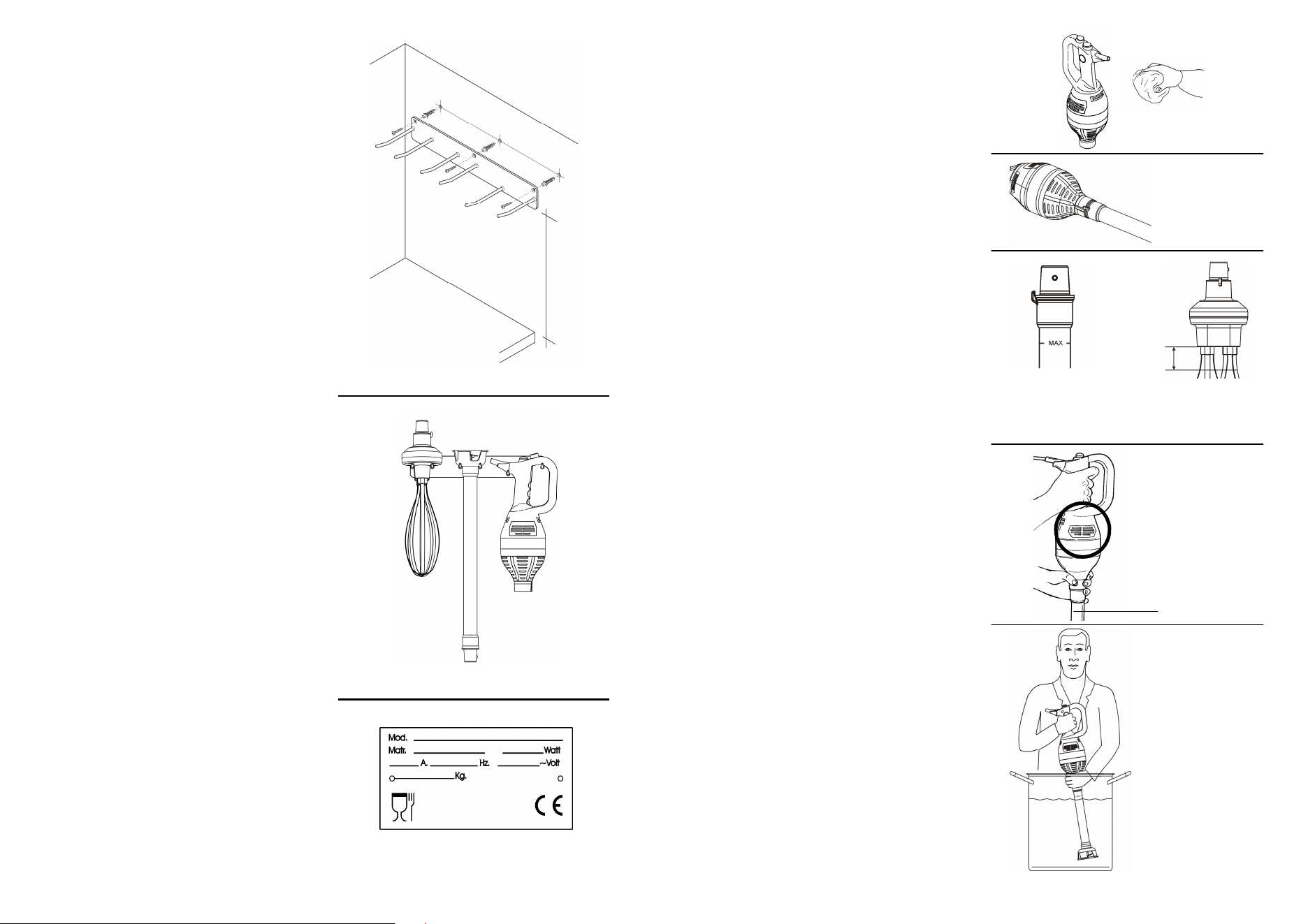
5.1 - ACCESSORIES ASSEMBLY
The tools must be installed on the engine’s
body when the machine is unplugged.
All the dipping blender’s tools are perfectly
interchangeable. However, they might differ
according to the model, date of production,
producer. Hence, it is recommended to
keep separate the various accessories of
other dipping blenders.
ENGINE’S BODY - SHAFT (Fig. 36)
Grip the engine’s body by the handle, grip
the shaft with the other hand. Align the
shaft’s rung to the clutch of the machine’s
body (1). Insert the shaft deeply (2) and ro-
tate it of about 90 degrees anticlockwise till
the shaft is firmly blocked to the machine(3).
The catch will fit the engine’s body refer-
ence.
ENGINE’S BODY - WHIP (Fig. 36)
Grip the engine’s body by the handle, grip
the whip with the other hand. Align the
shaft’s rung to the clutch of the machine’s
body (1). Insert the shaft deeply (2) and ro-
tate it of about 90 degrees anticlockwise till
the whip is firmly blocked to the machine(3).
The catch will fit the engine’s body refer-
ence.
WHIP’S DISASSEMBLY (Fig. 37)
The stainless steel whips can be disassem-
bled from the body of whips. Wear protec-
tive gloves. Hold the body firmly with one
hand and with the other one grip the whip
by the hooking base and pull towards the
opposite direction with strength but without
wrenching it till the piece is subdivided into
two pieces (2). Proceed in the same way
with the other whip (4).
In order to disassemble do the opposite.
CHAP. 5 - USE OF THE MACHINE
(1) (2)
(3)
(4)
(5)
(1) (2)
(3)
Fig. n°36
Fig. n°37
11
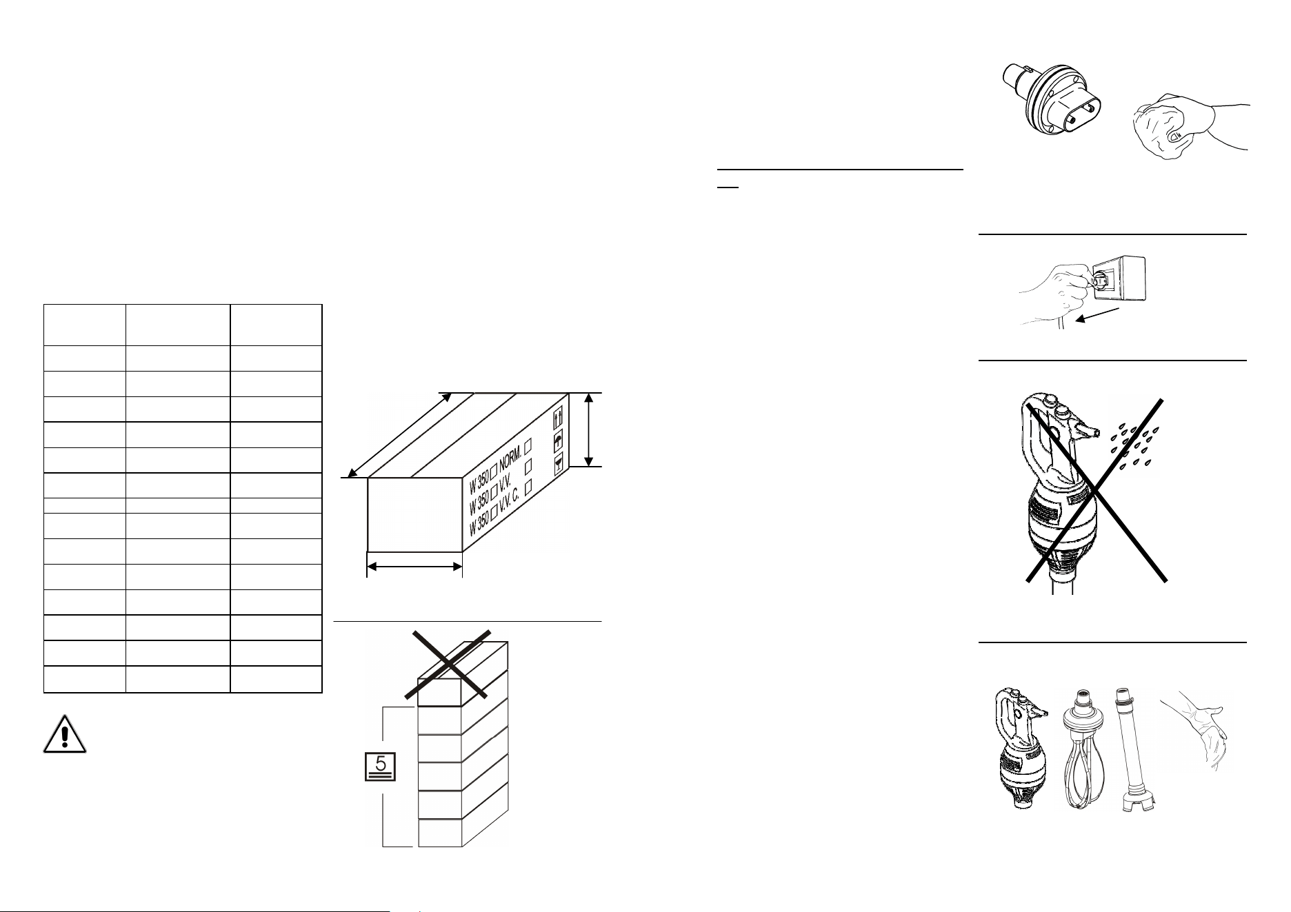
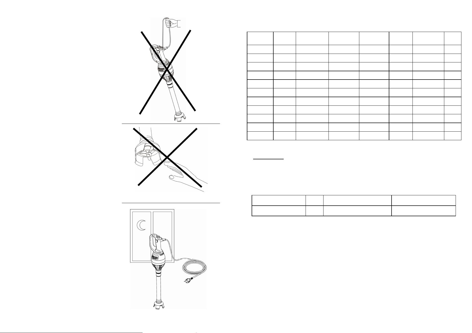
•
Do not wash the blender by means
of the dishwasher or water jets (Fig.
22-23)
•
The dipping blender has been de-
signed to blend fruit, vegetables and
meat non-frozen boneless fruit,
vegetables and meat to blend non-
frozen boneless fruit, vegetables
and meat in liquid suspensions
consisting of water or broth, at a
maximum temperature of 70° C
(Fig. 24), and anyhow food that is
not particularly hard or resistant to
be processed. Any other use is to be
considered improper and therefore
dangerous.
•
The whisk accessory is designed to
whip and emulsify fluids such as
cream, eggs, etc. at room tempera-
tures <25°C. It has not been de-
signed neither to cut nor to knead.
Any other use is to be considered
improper and therefore dangerous.
•
Dry the machine’s body and the
used accessories after having
cleaned them.
•
Do not expose the blender to nox-
ious agents such as the sun, the
rain, splashes, humidity, frost (Fig.
25).
•
Do not pull the feeding cable to un-
plug (Fig. 26).
•
Check the status of the feeding ca-
ble on regular basis as a worn out
cable or imperfect presents serious
electrical dangers, call the Customer
Service Centre.
•
Regularly check the condition of the
power cord; a damaged or worn
cord constitutes a serious electrical
hazard, therefore contact the Ser-
vice Centre.
•
Regularly check the condition of the
power button: if dirty or damaged, it
Fig. n°22
Fig. n°23
Fig. n°24
Fig. n°25
Fig. n°26
12
could be very dangerous, therefore
contact the Service Centre.
•
If the machine remains unutilised for
a long time, have it checked by an
Customer Service Centre before us-
ing it.
•
If the machine shows signs of mal-
functioning, it is recommended to
switch it off, not to use it and not to
intervene directly.
•
to repair it and call the Customer
Service Centre whose details can
be seen at the back of this manual.
•
In case of fall or immersion of the
blender, do not use it and contact
CUSTOMER SERVICE immediately
to have a detailed check.
•
Do not leave the dipping blender
plugged in pointlessly. Unplug it
when not using the machine. (Fig.
29)
•
Do not hang f handle the dipping
blender by means of the feeding ca-
ble (Fig. 27).
•
Even if the machine is built accord-
ing to the enforcing laws, there are
some dangerous zones. Therefore,
it is recommended to avoid to ap-
proach the hands to the blades or
other parts in movement (Fig. 28).
•
Do not posture in such a way that
might lead parts of the body in
direct contact with the blades.
Fig. n°27
Fig. n°28
Fig. n°29
17
ATTENTION:
The electrical features of the machine are indicated by a plate placed by the grip (Fig. 15).
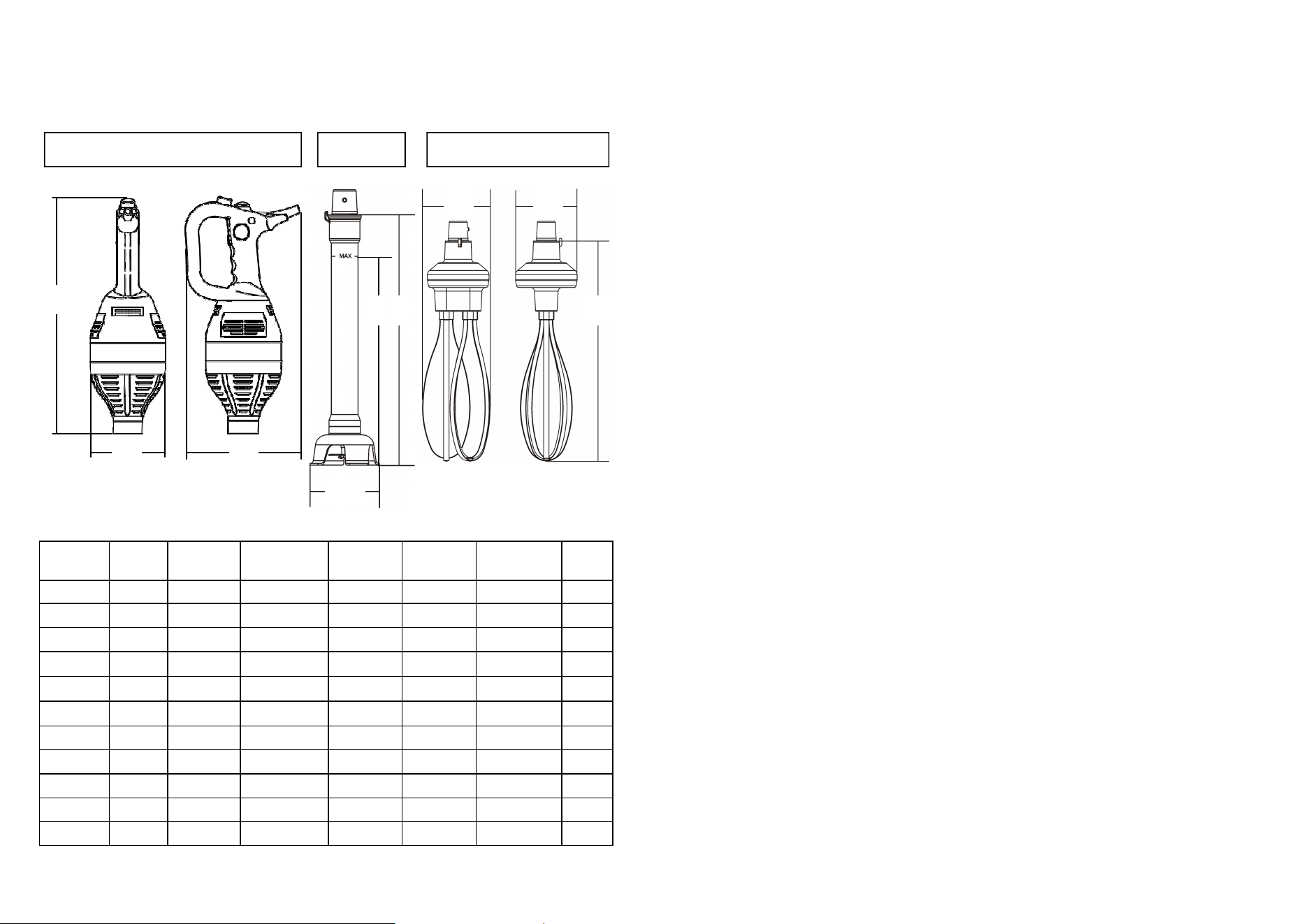
TABLE 2 - OVERALL DIMENSIONS AND TECHNICAL FEATURES (Fig.35)
W 43
430/0,60 1ph 13.000 1.850 100 125x190x377 2,5
W 43 VT
430/0,60 1ph 2.200÷11.500 350÷1.800 100 125x190x377 2,5
W 55
550/0,80 1ph 13.500 1.900 200 125x190x385 3,5
W 55 VT
550/0,80 1ph 2.200÷11.500 350÷1.800 200 125x190x385 3,5
W 75
750/1,0 1ph 14.000 1.950 300 125x190x390 4
W 75 VT
750/1,0 1ph 2.200÷11.500 350÷1.800 300 125x190x390 4
Whips
- - - - - 117x113x385 2
AxC / D
Shaft 35
- - - - - 100x145 / 350 1
Shaft 45
- - - - - 100x515 / 450 1,5
Power Power
source
Knives
revolutions
Whisk
revolutions
Working
capacity
Dimensions
AxBxC
Net
weight
Watt/Hp r.p.m. r.p.m. lt mm kg
W 200-280-360 / VT W 430-550-750 / VT
Noise level
dB
≤ 85 ≤ 85
16
voked by the blade and the dragging device, by the whip and by other components of
the machine or by electrocutions.
4.4 - OVERALL DIMENSIONS, WEIGHT, FEATURES
Fig. n°35
Hand-Held Mixer (body only) Shaft Whips
C C
B A
A
D
C
A B
TABLE 1 - OVERALL DIMENSIONS AND TECHNICAL FEATURES
(Fig. 35)
Power Power
source
Knives
revolutions
Whisk
revolutions
Working
capacity
Dimensions
AxBxC
Net
weight
Watt/Hp r.p.m. r.p.m. lt mm kg
W 20
200/0,27 1ph 16.000 2.300 20 100x182x340 2
W 20 VT
200/0,27 1ph 2.300÷16.000 350÷2.450 20 100x182x340 2
W 28
280/0,38 1ph 16.000 2.300 40 100x182x340 2,2
W 28 VT
280/0,38 1ph 2.300÷16.000 350÷2.450 40 100x182x340 2,2
W 36
360/0,50 1ph 16.000 2.300 70 100x182x348 2,5
W 36 VT
360/0,50 1ph 2.300÷16.000 350÷2.450 70 100x182x348 2,5
Whips
- - - - - 106x113x348 2
AxC
Shaft 25
- - - - - 94x250 0,5
Shaft 35
- - - - - 94x320 1
13
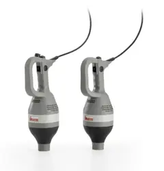
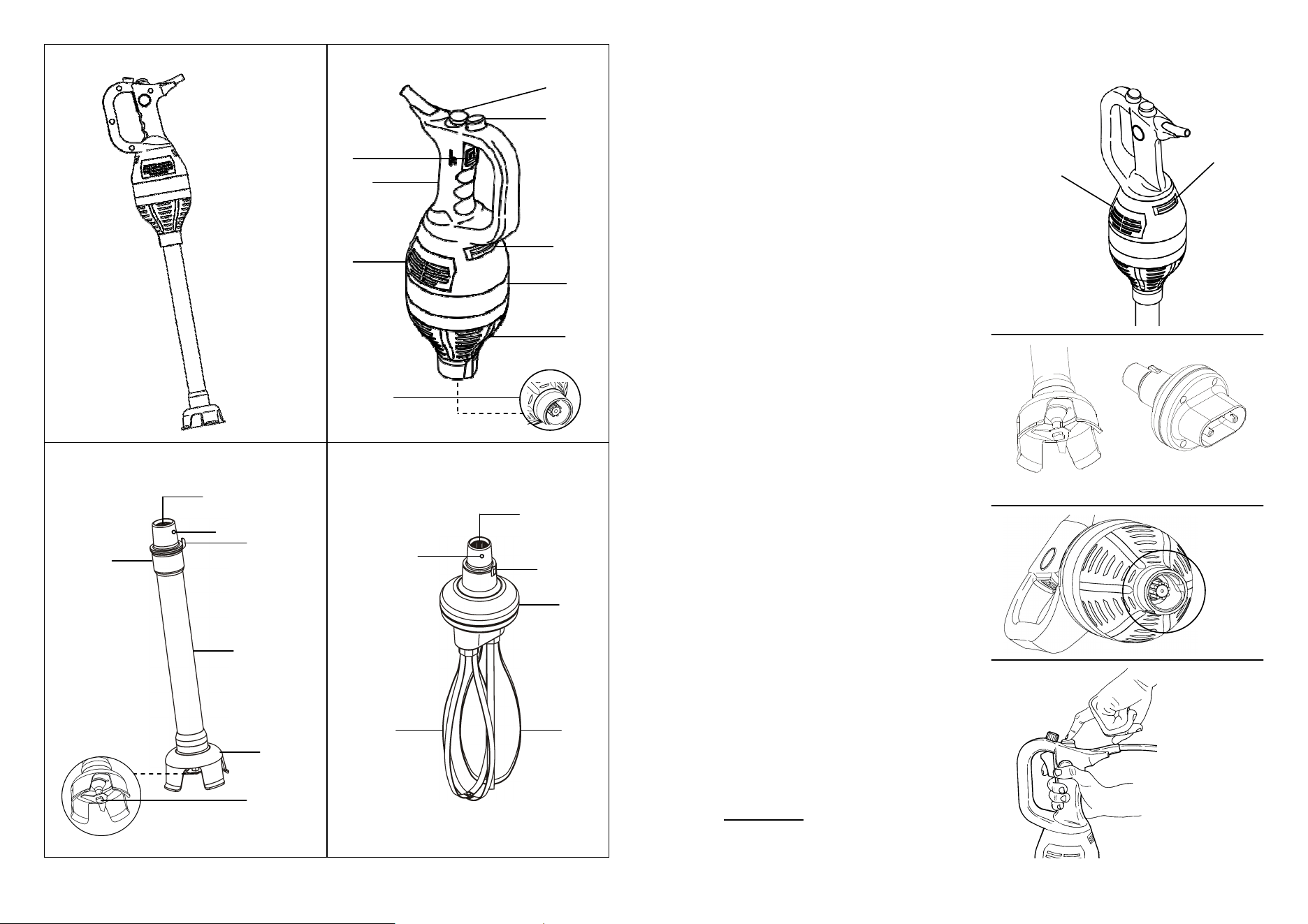
CHAP. 4 - GETTING ACQUAINTED WITH THE MACHINE
4.1 - MACHINE’S DESCRIPTION
The dipping blender is made up by more elements than the ones that in this
manual are named (Fig. n.30):
-
Engine’s body
-
Operating shaft
-
Operating whip
4.2 - IN-BUILT FEATURES
The engine’s body is built in highly-resistant ABS with stainless steel and alumin-
ium details. These materials guarantee hygiene when there is contact with food
and good resistance to the agents contained by food. Moreover, high mechanical
resistance is guaranteed due to their formation.
The operating shaft is made up almost completely by stainless steel, the main
body in die-casted aluminium and coated in highly-resistant ABS.
The perfectly-insulated and watertight mechanical components inside it are
made of stainless steel for a long-lasting resistance.
The wall bearing is made of stainless-steel just like the kettle support.
The wall suitcase is made up by plastic material outside and punched sponge
inside.
KEY:
01 speed variator - optional 10 dragging device (female)
02 upper-grip handle 11 hooking rung
03 air-exhaust grill 12 shaft/whip blocking device
04 band 13 graduated tube
05 lower grip 14 bell
06 dragging device (male) 15 blade
07 air-aspiration grill 16 whips’ body
08 switch 0/I 17 whip’s insert
09 hooking cone 18 switch auto-blocking
14
Fig. n°30
Engine’s body
Dipping blender
Operating shaft
Operating whip
01
02
03
04
05
08
07
06
10
12
11
16
17 17
10
12
13
14
9
11
15
18
15
Fig. n°33
4.3 - IN-BUILT SAFETY DEVICES
4.3.1 - Mechanical safety devices
As far as mechanical-nature safety, the dip-
ping blender described by this manual com-
plies to:
- the UL 763 norm
- the CSA C22.2 nr 195 norm.
The dipping blender is provided with:
- Whip-protecting bell (Fig. 32 –ref.b)
- Shaft-protecting bell (Fig. 32 – ref.a)
- Dragging device inserted engine’s stem
(Fig. 33)
- Respect of the minimum space to grip
the machine as per what is prescribed
by law
- Maximum liquid level marked on the
shaft (Fig. 45)
4.3.2 - Electrical safety devices
As far as electrical-nature safety, the dip-
ping blender described by this manual com-
plies to:
- the UL 763 norm
- the CSA C22.2 nr 195 norm.
Therefore the dipping blender is provided
with:
- Double-insulating system to guarantee
that all the details that might come in
contact with the operator are not subject
to tension not even in case of break-
down.
- Button located in a position suitable for
preventing accidental start-up (Fig. 34).
- Internal components protection from liq-
uid splashes
- Although the dipping blender is provided
with the electrical and mechanical meas-
ures (operating during the working
phase and during cleaning and mainte-
nance) as per the enforcing laws, there
are some RESIDUAL RISKS that can-
not be eliminated completed. These are
recalled by this manual under the titles
ATTENTION. They concern the danger
of cut, contusion and else that is pro-
Fig. n°34
Aspiration
grill air
Escape
grill air
Fig. n°32
(a)
(b)
Fig. n°31