
CDX EV Controller
2026
User Manual
Version: 1.1
Publish date: 24/03/2026

CDX TECHNOLOGY EUROPE B.V. - CDX EV Controller 1
Copyright
Information in this document is subject to change without notice. Trademarks, trade names, service marks or
service names owned or registered by any other company and used in this document are property of the
respective companies.
Disclaimer
Information contained in this document is confidential, privileged and only for the information of the intended
recipient and may not be used, published, or redistributed without the prior written consent of CDX Technology
Europe B.V.
Safety
This product is designed to assist in improving safety on a go-karting track. While it may help reduce certain risks
when used correctly, it does not eliminate hazards associated with go-karting activities and cannot replace
proper track safe operating procedures, trained personnel, or compliance with applicable safety regulations.
While every effort has been made to ensure the accuracy of the information contained in this manual, the
manufacturer cannot be held responsible for errors, omissions, or inaccuracies in this publication.
Copyright © 2026 CDX Technology Europe B.V.
FCC ID: 2BUQO-CDX-EVRC2301
Contact details
Address:
Meander 551
6825 MD Arnhem
The Netherlands
General inquiries:
https://www.cdx-technology.com
Main office:
+31 85 2006 480
Technical support:
+31 6 1417 0924
Technical support email:
support@cdx-technology.com

CDX TECHNOLOGY EUROPE B.V. - CDX EV Controller 2
FCC statement
Product name: CDX EV Controller
Responsible party: CDX Technology Europe B.V.
Address: Meander 551, 6825 MD Arnhem, the Netherlands
Website: https://www.cdx-technology.com
Tel: +31 85 2006 480
E-mail: support@cdx-technology.com
This device complies with part 15 of the FCC Rules. Operation is subject to the following two conditions:
1. This device may not cause harmful interference, and
2. This device must accept any interference received, including interference that may cause undesired
operation. Any Changes or modifications not expressly approved by the party responsible for compliance
could void the user's authority to operate the equipment.
Note: This equipment has been tested and found to comply with the limits for a Class A digital device, pursuant to
part 15 of the FCC Rules. These limits are designed to provide reasonable protection against harmful interference
when the equipment is operated in a commercial environment. This equipment generates, uses, and can radiate
radio frequency energy and, if not installed and used in accordance with the instruction manual, may cause
harmful interference to radio communications. Operation of this equipment in a residential area is likely to cause
harmful interference in which case the user will be required to correct the interference at his own expense.

CDX TECHNOLOGY EUROPE B.V. - CDX EV Controller 3
DOCUMENT REVISIONS
Version
Details
Date
Author
0.1
Initial user manual
CDX EV Controller.
10-12-2025
WH
0.2
Added pinout.
15-12-25
WH
0.3
Update of document.
16-12-2025
TF/WH
0.4
Changed layout and
added text.
17-12-2025
JFL/KKS
0.5
Update of document.
12-01-2026
CM/HV
0.6
Small changes, and
correcting the
technical data.
13-01-2026
WH
1.0
First version release.
15-01-2026
JFL/KKS
1.1
Processed feedback
Applus.
24-03-2026
KKS

CDX TECHNOLOGY EUROPE B.V. - CDX EV Controller 4
TABLE OF CONTENTS
1 INTRODUCTION ................................................................................................................................. 5
1.1 Package contents ...................................................................................................................................................... 5
1.2 Compatible expansion components .......................................................................................................................... 5
1.3 Overview of product features .................................................................................................................................... 6
2 INSTALLATION GUIDE ......................................................................................................................... 7
2.1 Mounting instructions ............................................................................................................................................... 8
2.2 Connector overview .................................................................................................................................................. 8
2.3 Digital outputs ........................................................................................................................................................... 9
3 OPERATING INSTRUCTIONS .............................................................................................................. 10
3.1 Speed restriction ..................................................................................................................................................... 10
3.2 7-segment display ................................................................................................................................................... 10
3.3 Segment Slowdown ................................................................................................................................................. 10
4 SYSTEM CONFIGURATION ................................................................................................................ 11
4.1 Configuration terminal ............................................................................................................................................ 11
4.2 Switch table............................................................................................................................................................. 11
5 TECHNICAL DATA ............................................................................................................................. 12
5.1 Mounting points ...................................................................................................................................................... 13
CDX TECHNOLOGY EUROPE B.V. - CDX EV Controller 5
1 Introduction
The CDX EV Controller is an electronic device, functioning exclusively as a radio receptor, designed to limit the
maximum speed of an electric go-kart. See Chapter 5 (Technical data) for frequency and antenna details. The
device can be controlled via a dedicated remote control or through external third-party software integration. The
CDX EV Controller is designed to support operational safety on and around the go-karting tracks. This product is
intended as a supplementary safety enhancement device and does not replace driver supervision and track
control procedures.
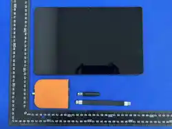
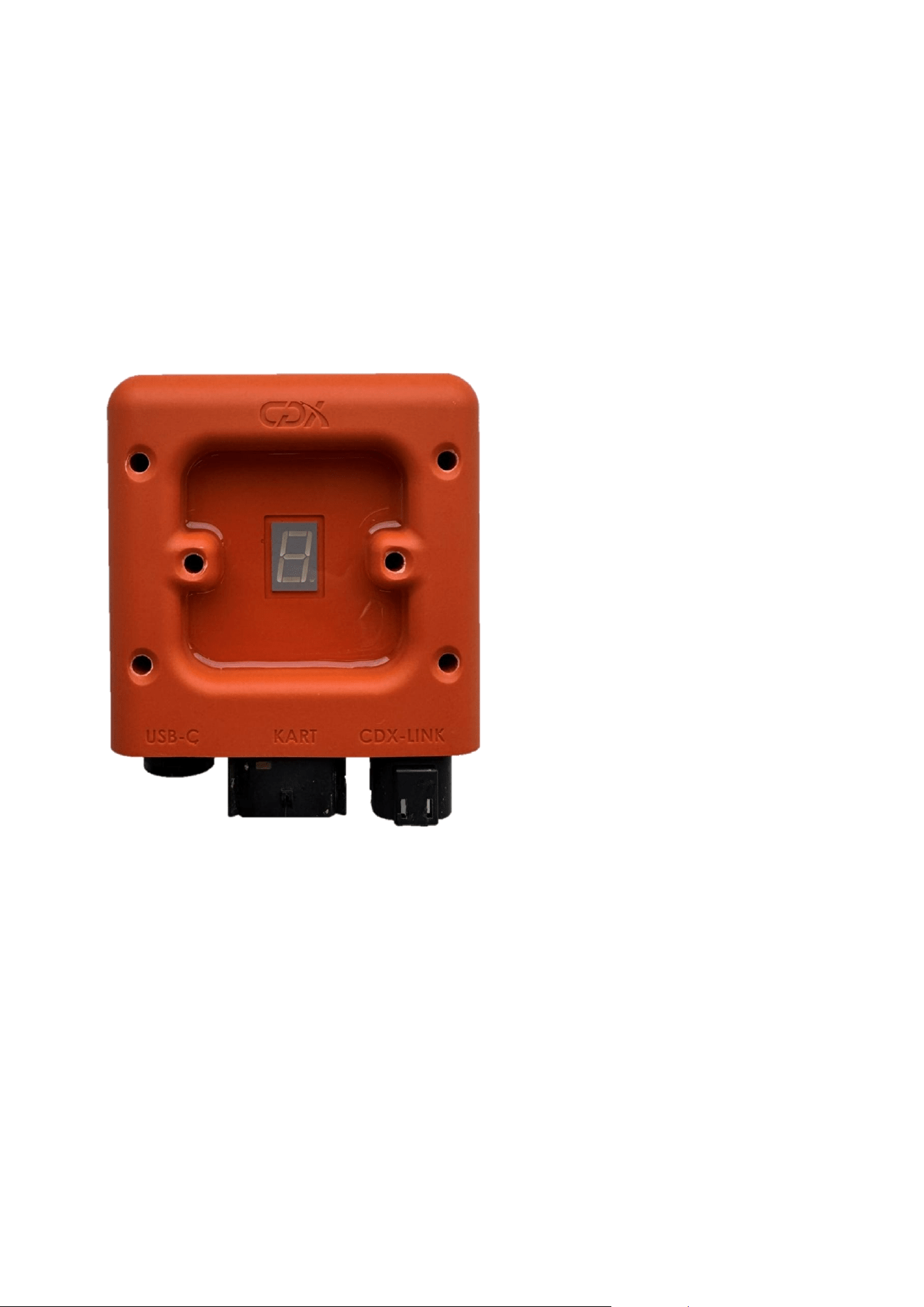
1.1 Package contents
The CDX EV Controller is the only item that is supplied in the box which is shown in Figure 1.
Figure 1: CDX EV Controller
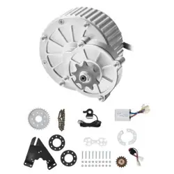
1.2 Compatible expansion components
- CDX Timing Sensor
o The CDX EV Controller can be combined with the CDX Timing Sensor for additional timing and
segment speed limiting.
- CDX Phone Transceiver
o To request speed presets on the CDX EV Controller from a handheld device.
- CDX Tablet Transceiver
o To request speed presets on the CDX EV Controller from a fixed device.
- CDX Mini Remote
o To request speed presets on the CDX EV Controller from a handheld device.
CDX TECHNOLOGY EUROPE B.V. - CDX EV Controller 6
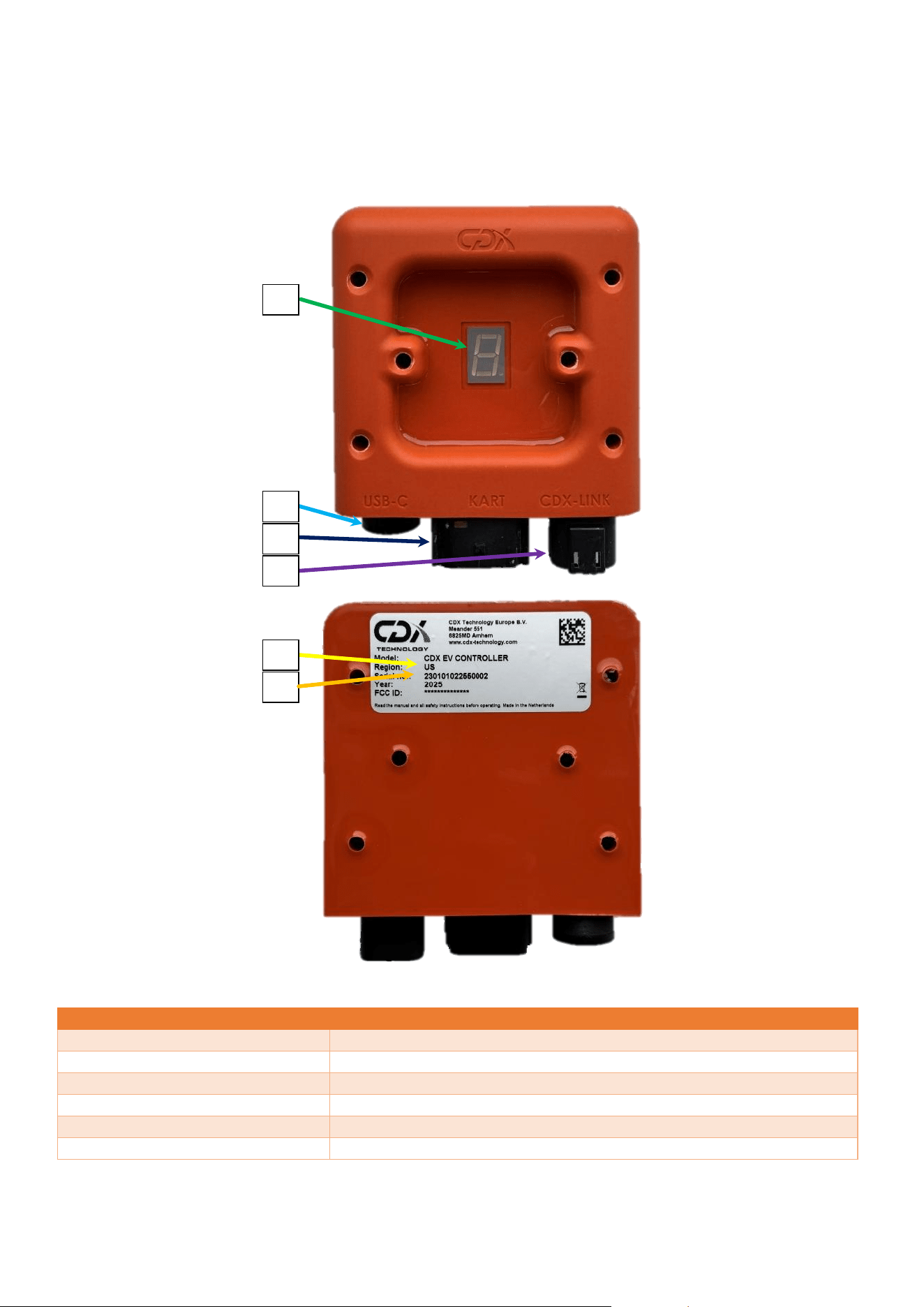
1.3 Overview of product features
Figure 2 shows an overview of the product and its main features.
Figure 2: CDX EV Controller with important parts highlighted
NUMBER
DESCRIPTION
1.
Speed setting display
2.
USB connector
3.
Kart connector
4.
CDX-Link connector
5.
Region
6.
Serial number
1
2
3
4
5
6
CDX TECHNOLOGY EUROPE B.V. - CDX EV Controller 7
2 Installation Guide
In this chapter the installation of the EV controller is detailed. How to mount the EV controller properly, while
maintaining the optimal radio reception. Additionally, the connector functions and pinout are shown, as well as
the digital outputs used to control the speed of the kart.
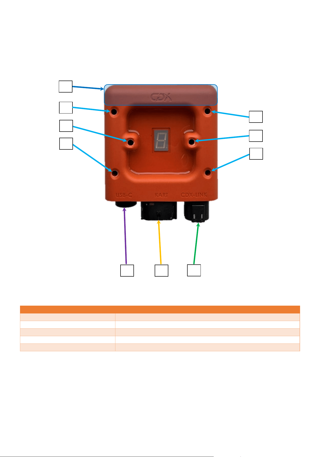
Figure 3: CDX EV Controller with main components highlighted
NUMBER
DESCRIPTION
1.
PCB antenna location
2.
M5 mounting holes
3.
USB-C connector
4.
Kart connector
5.
CDX-Link connector
1
2
2
2
2
2
2
3
4
5
CDX TECHNOLOGY EUROPE B.V. - CDX EV Controller 8
2.1 Mounting instructions
The EV controller has a total of 6 M5 mounting holes, shown in Figure 3, used for mounting the device on a flat
surface. The 6 mounting holes can be used to mount the device with M5-sized bolts and nuts. Additionally, if
preferred, the device can be mounted with tie wraps. Do not overtighten the mounting of the device, as this may
deform it and prevent proper functioning.
To achieve the optimal radio reception performance from the EV controller, it should be placed as high as
possible on the kart. The region of the antenna, which is shown in Figure 3, should not be blocked by metal and
other RF interfering obstacles such as cables.
2.2 Connector overview
The EV controller contains 3 connectors, shown in Figure 3. a USB-C connector, a Kart connector and a CDX-Link
connector. The Kart connector is required to limit the speed of the kart. The other connectors are for optional
extra functionality and not necessary for limiting the speed of the kart.
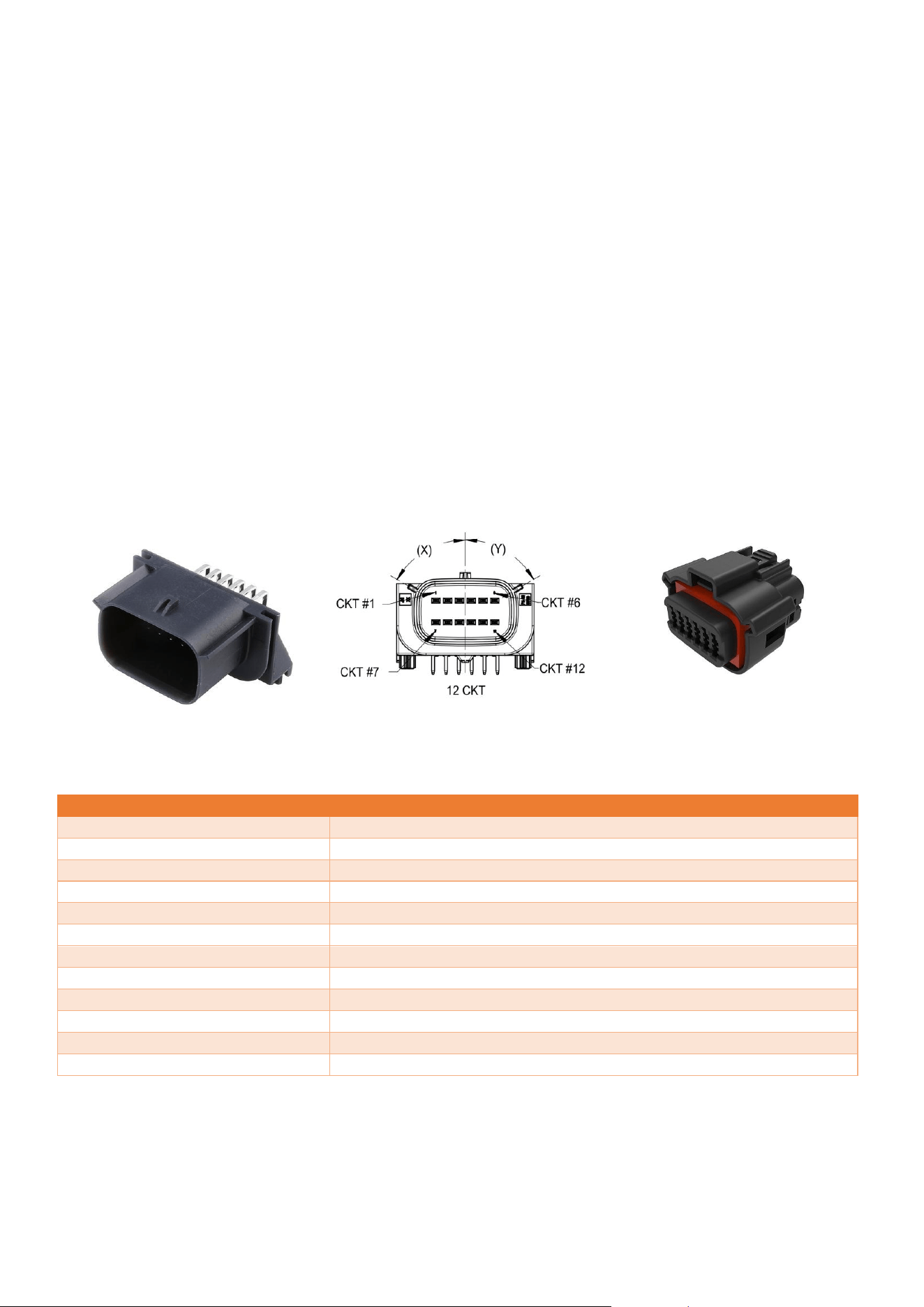
2.2.1 Kart connector
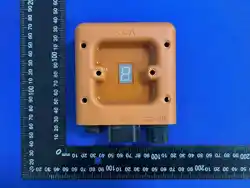
The Kart connector is an MX120G automotive connector, type 36783-1201 shown in Figure 6. The visual pinout of
the Kart Connector is shown in Figure 5. The counterpart connector (female) is the 36792-1201, which is shown in
Figure 4.
PIN
FUNCTION
1.
Battery +
2.
Kart output 3 (digital)
3.
Kart output 2 (digital)
4.
Input 2 (digital)
5.
Kart output 4 (digital)
6.
GND for digital signals
7.
Battery -
8.
Kart output 1 (digital)
9.
Input 1 (digital)
10.
Unbrick - for service use
11.
CAN low - optional
12.
CAN High - optional
Figure 6: 3D model 36783-1201
Figure 5: Schematic view 36783-1201
Figure 4: 3D model 36792-1201
CDX TECHNOLOGY EUROPE B.V. - CDX EV Controller 9
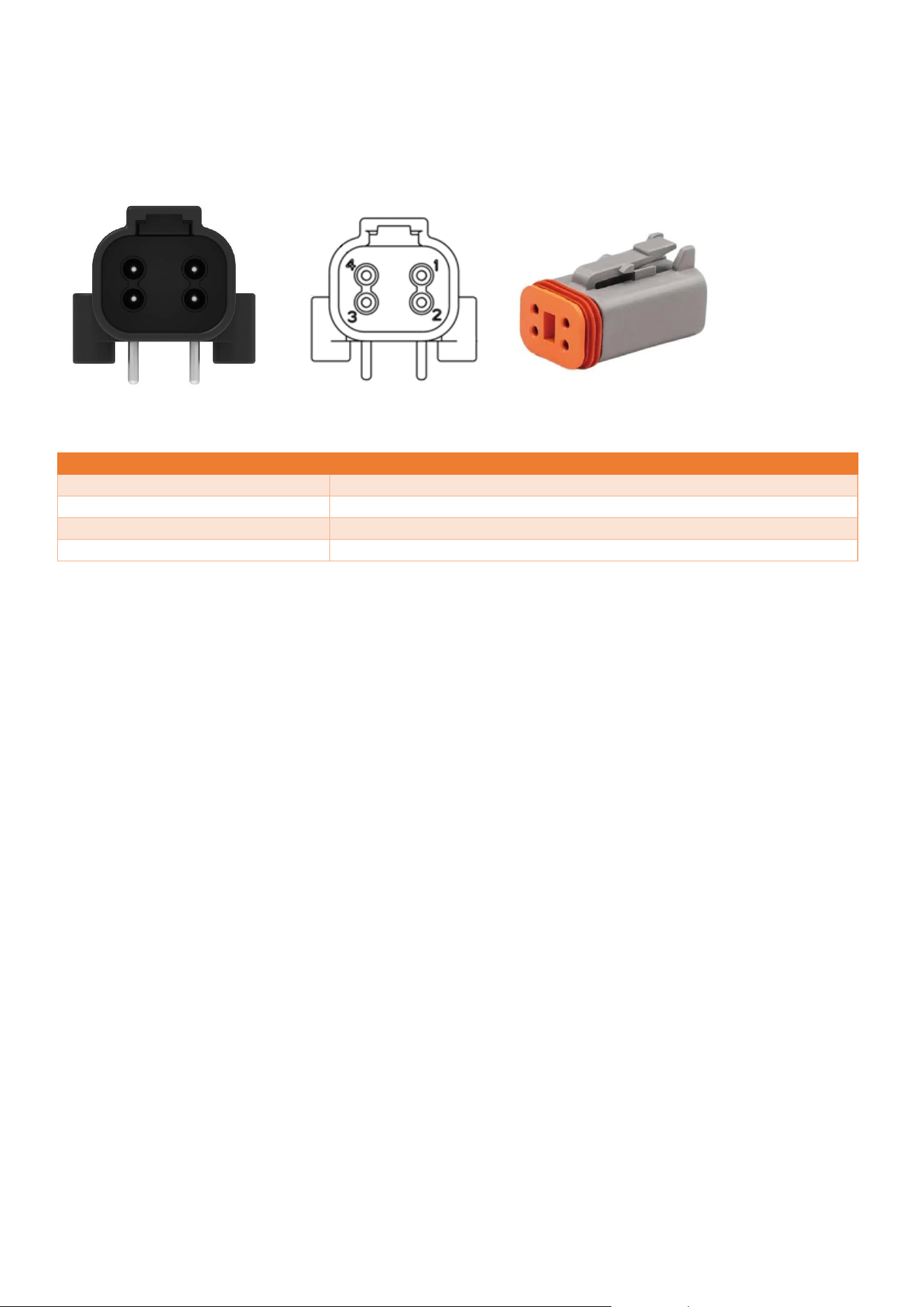
2.2.2 CDX Link connector
A 4 pin automotive connector, DTF13-4P (Figure 9), is used for the CDX link connector. Figure 8 visually shows the
pinout of the CDX link connector. The counterpart connector (female) is the DT06-4S (Figure 7).
Figure 9: 3D model DTF13-4P
PIN
FUNCTION
1.
GND
2.
RS232 TX
3.
RS232 RX
4.
Vout
See Chapter 5 (Technical data) for more details.
2.2.3 USB-C
The USB-C connector can be used to configure the EV controller, which is explained in Chapter 4 (System
Configuration). The counterpart connector (male) needs to be a USB 2.0 data cable, USB A to USB C cable. Any
other cable that is used for USB-C connection is not recommended and proper working is not guaranteed. The EV
controller comes with a sealing screw on the USB-C connector. To prevent contamination in the connector, the
screw should remain in place during normal use, otherwise normal operation is not guaranteed.
2.3 Digital outputs
The EV controller has 4 digital outputs, each digital output can be configured to work in tri-state. Tri-state can
assume a high output (logical 1), a low output (logical 0) or high impedance (floating). This configuration can be
done by user, the process of which is described in Section 4.1 (Configuration terminal). See Chapter 5 (Technical
data) for technical details.
Figure 7: 3D model DT06-4S
Figure 8: Schematic view
DTF13-4P
CDX TECHNOLOGY EUROPE B.V. - CDX EV Controller 10
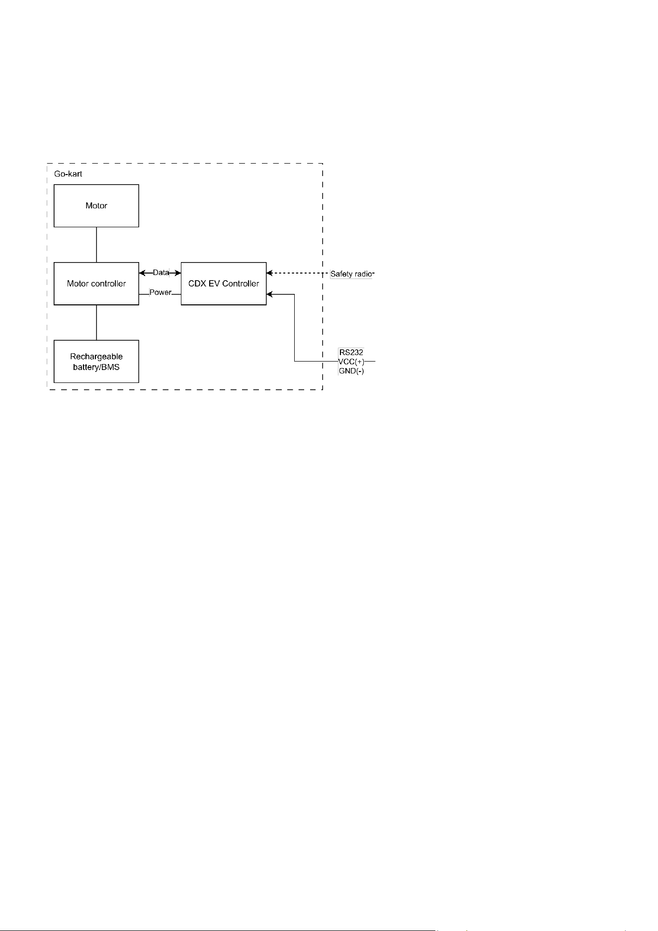
3 Operating instructions
This chapter describes how the EV controller operates. Figure 10 visually shows the typical configuration. The
safety radio message is received from an user that transmits speed control messages by a CDX Remote. See the
corresponding user manual for further information.
Figure 10: Typical configuration EV controller
3.1 Speed restriction
The EV controller communicates speed presets to the motor controller using 4 digital outputs. The value of each
individual digital output is determined based on the speed-preset currently active on the CDX EV Controller
defined by the user-configurable switch table.
3.2 7-segment display
The 7-segment display is used to display the current speed setting active on the CDX EV Controller. The speed
setting can range from speed 0 (stop) to 8. The display is also used to indicate that the radio is functioning
properly. This is done by toggling the dot in the 7-segment display when a valid radio message is received.
3.3 Segment Slowdown
Segment slowdown is a feature of the CDX EV Controller that allows slowdown in certain sections of the track.
There are additional CDX devices required to use segment slowdown. The CDX Loop is required to create track
segments and the CDX Sensor is required to detect the track segments. This enables the EV Controller to
automatically slow down when driving over the start of a segment, and to return to its previous speed setting on
the end of a segment.
When the CDX EV Controller receives two different speed commands—one from the CDX Sensor and one from
the CDX Phone/Tablet transceiver—the lowest speed is applied. This ensures that slowdown segments cannot be
overridden by a remote command requesting a higher speed, and vice versa.

CDX TECHNOLOGY EUROPE B.V. - CDX EV Controller 11
4 System Configuration
The CDX EV Controller has various features, some of which are enabled when using CDX products and some that
interface with the CDX-Link port. In this paragraph the information about segment slowdown, Track ID and Track
PIN are noted.
4.1 Configuration terminal
When the USB is connected, the CDX EV Controller can be configured using a serial terminal program. The
terminal program can be used to alter the switch table. Additionally, it can also be used to alter the Kart ID and
Track IDs of the CDX EV Controller.
4.1.1 Track ID and Track PIN
The Track ID and Track PIN feature allows the logical segmentation of multiple CDX EV controllers into separate
control groups.
By default, the Track-ID is set to ‘0000’ and Track-PIN is set to ‘0000’. In this default configuration, the CDX EV
controller accepts speeds commands from all compatible control interfaces, regardless of the Track ID and Track
Pin settings of the remote. This default behavior allows unrestricted communication during initial setup and
commissioning.
The use of a Track ID and Track-PIN is recommended to be used when two separate groups of karts (for example,
track 1 and track 2) are operating simultaneously within the same go-kart facility and separate control of each
group is required.
The Track ID and Track Pin can also be used to limit control access to a defined group of controllers by updating
these parameters when required.
The Track-ID and Track-PIN must be configured in the configuration tool and stored within the CDX EV controller.
After configuration, the corresponding Track ID and Track PIN must also be configured in the control interface
application to control the associated CDX EV Controllers.
4.1.2 Segment Slowdown
The speed limits per track segment are configured in the CDX Sensor and CDX Loop. See the corresponding user
manual for further information.
4.2 Switch table
The switch table is the configuration of what outputs of the EV controller are set to High, Low or Floating at every
speed. This switch table is configured using the configuration terminal. See the corresponding user interface
manual for further information. For more details see Chapter 5 (Technical data).
For example, if the switch table is configured as shown in Table 1. When the EV controller is set to speed 1,
output 2 to output 4 will be set to Low and output 1 will be set to High. If the connected motor controller has the
corresponding switch table, speed 1 is detected.
Output1
Output2
Output3
Output4
Speed 0
L
L
L
L
Speed 1
H
L
L
L
Speed 2
L
H
L
L
Speed 3
L
L
H
L
Speed 4
L
L
L
H
Table 1: Switch table example
CDX TECHNOLOGY EUROPE B.V. - CDX EV Controller 12
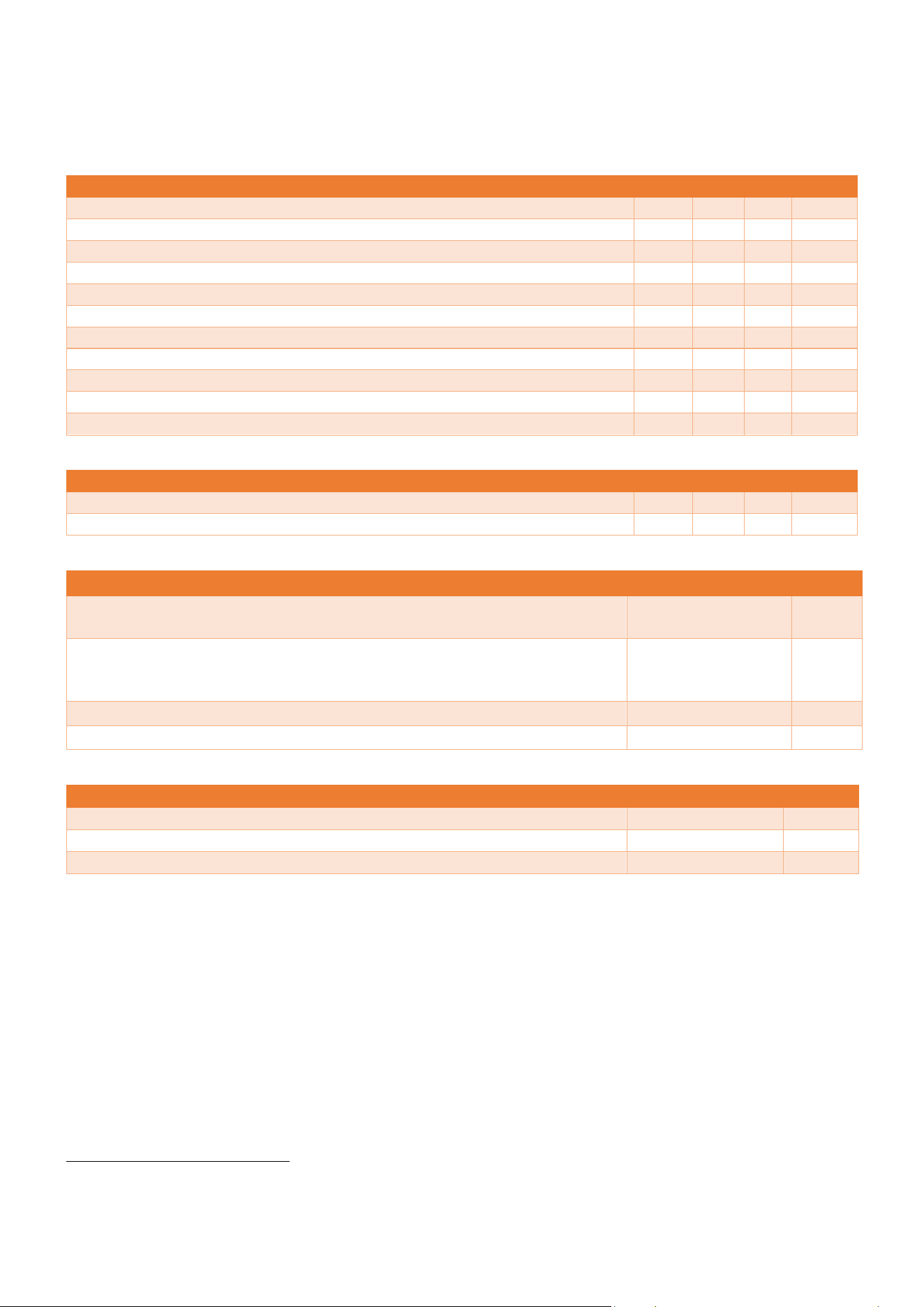
5 Technical data
This chapter presents the technical data in tables by category.
Electrical characteristic
Min
Typ.
Max
Unit
Operational voltage
8
24
60
V (DC)
Power consumption
500
mW
Current draw (48V)
10
mA
Digital output High
14
V (DC)
Digital output Low
0
V (DC)
CDX-Link Vout
14
V (DC)
CDX-Link RS232 TX High (logical 0)
5
5.4
V (DC)
CDX-Link RS232 TX Low (logical 1)
-5.4
-5
V (DC)
CDX-Link RS232 RX High (logical 0)
3
15
V (DC)
CDX-Link RS232 RX Low (logical 1)
-15
-3
V (DC)
KART interface digital outputs
±10
mA
Environmental characteristic
Min
Typ.
Max
Unit
Operational temperature
1
0
65
°C
Storage temperature
-20
80
°C
Radio characteristic
Unit
Receiving radio frequency
869 (Europe),
908 (North America)
MHz
Radio modulation
Direct sequence
spread spectrum
(DSSS)
Radio antenna
PCB antenna
Radio antenna gain
4.85
dBi
Physical characteristic
Unit
Dimensions (Length × Width × Height)
117 × 100 × 35
mm
Mounting hole diameter
5
mm
Housing material
Polyurethane (PUR)
1
Upon request, wider temperature ranges are available.
CDX TECHNOLOGY EUROPE B.V. - CDX EV Controller 13
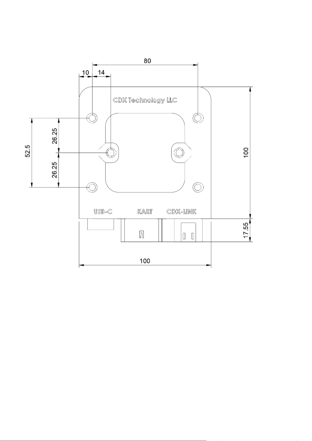
5.1 Mounting points
To mount the CDX EV Controller, 6 M5 holes are present. The location and dimensions can be seen in Figure 11.
The device is provided with six mounting holes suitable for use with M5 bolts and nuts. It is recommended to use
a minimum of three mounting holes to securely attach the device.
As an alternative, the device may be mounted using tie wraps, provided that the mounting method securely
retains the device during operation.
Do not overtighten the mounting hardware, as excessive force may deform the enclosure and affect device
operation.
The CDX EV Controller should not be mounted in close proximity to the motor or other high-current components,
as this may adversely affect radio communication. Further installation information can be found in Chapter 2,
Section 2.1 (Mounting instructions).
Figure 11 CDX EV Controller size schematic