
UHF Industrial Reader User
Manual
Suitable for ARU5321M&x-S04
◆ Before you use this product, please read this manual carefully and properly keep it
for future reference.
◆ As our products continue improving, they may be changed without advanced
notice.
◆ The copyright of this manual belongs to our company. Unauthorized plagiarism or
dissemination will be held legally responsible.
Version: V1.0

User manual
Contents
1. Product Overview ....................................................................................................1
1.1. Introduction ...................................................................................................1
1.2. Product Features ............................................................................................1
1.3. Product Pictures ............................................................................................2
1.4. Main Parameter .............................................................................................3
2. Hardware Interface Description ...............................................................................3
3. Communication Connection .....................................................................................5
3.1. Ethernet Connection Instructions ..................................................................5
3.2. Serial Port Connection Instructions ...............................................................5
3.3. Connector Instructions ..................................................................................6
3.3.1. Ethernet Cable ..................................................................................6
3.3.2. One-to-Two Debugging Cable ..........................................................7
3.3.3. DC Power Supply and Serial Communication Cable ........................7
3.3.4. IO Separation Cable ..........................................................................7
3.3.5. 2-Way Splitter ...................................................................................8
4. Indicator Light Description ......................................................................................9
5. Technical Support ....................................................................................................9

User manual
Guangzhou Andea Electronics Technology Co., Ltd. 1/9
http://www.gzandea.com
1. Product Overview
1.1. Introduction
ARU5321M&x-S04 is a high-stability industrial-grade UHF RFID reader device,
integrated based on the UHF RF chip E710. It operates in the frequency band of
865~930MHz (customizable, including US standard 902~928MHz, EU standard
865.6~867.6MHz, and national standard 920~925MHz), and supports reading tags that
comply with the ISO18000-6C and EPC Class1 Gen2 international standard protocol
formats.
The device has built-in filtering and isolation modules, providing strong
anti-interference capabilities for EMC. It also features easy operation, excellent sealing
and heat dissipation, high receiving sensitivity, stable performance, and high reliability.
Equipped with RS485 and TCP communication interfaces, the RS485 interface supports
the standard industrial communication protocol ModBus RTU, while the TCP interface
has multiple standard Ethernet industrial communication protocol versions including
ModBus TCP, PROFINET, EtherNet/IP, and CC-LINK IE FB, allowing users to easily
integrate it into PLC and other control systems. The reader integrates the RF
communication protocol internally, so users do not need to understand complex RF
communication protocols. They can achieve inventory UID, read storage area, and write
storage area by operating the holding registers and input registers inside the reader
through ModBus, PROFINET, EtherNet/IP, and CC-LINK IE FB commands.
ARU5321M&x-S04 is suitable for industrial applications such as automated
production lines, automated sorting systems, and component assembly lines. It can
connect up to 4 antennas for simultaneous operation.
1.2. Product Features
➢ Support ISO18000-6C, EPC Class1 Gen2 standard
➢ Communication interface: Industrial Ethernet, RS485
➢ Supports standard industrial communication protocols ModBus, PROFINET,
EtherNet/IP, CC-LINK IE FB, facilitating user integration into PLC and other
control systems
User manual
Guangzhou Andea Electronics Technology Co., Ltd. 1/9
http://www.gzandea.com
➢ Built-in filtering and isolation modules with strong anti-interference capabilities
for EMC
➢ Split design, supporting connection of up to 4 antennas for simultaneous operation,
enabling flexible distributed antenna installation and deployment
➢ IP67 protection rating, suitable for various harsh industrial environments
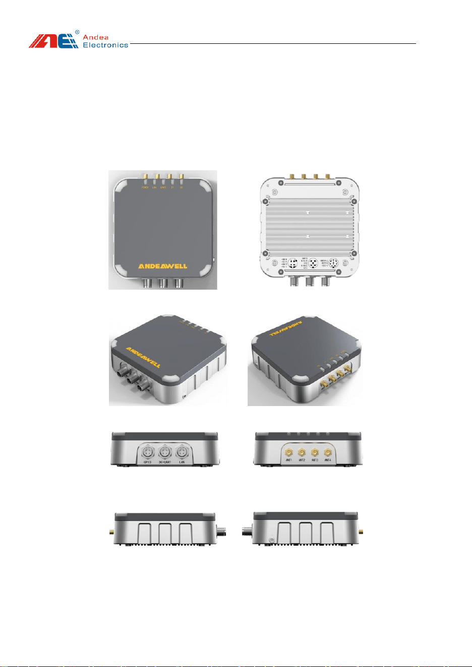
1.3. Product Pictures
Figure 1 Product appearance
User manual
Guangzhou Andea Electronics Technology Co., Ltd. 1/9
http://www.gzandea.com
1.4. Main Parameter
The detailed technical parameters of this product are as follows:
Table 1 Description of main technical parameters of the product
Parameter
Description
Operating Frequency
868MHz
Support Standard
ISO18000-6C, EPC C1G2 standard
RF Power
-0.41DBm
Communication Interface
Industrial Ethernet, RS485
Communication Protocols
ARU5321M&T: Modbus RTU, Modbus TCP
ARU5321M&P: Modbus RTU, PROFINET
ARU5321M&E: Modbus RTU, EtherNet/IP
ARU5321M&I: Modbus RTU, CC-LINK IE FB
Communication Rate
10/100M bps, 9600b/s~115200b/s
Power Supply Voltage
48V POE(46-54V), 24V DC(10~30V)
Maximum Current
<0.38A@24V DC
Indicator Lights
9 types of LED indicator lights
Dimensions
135*135*42mm(top cover size 130*130mm)
Weight
360g
Fixing Method
Fixed with nuts (4*M5) or with accessory brackets
Housing Material
ABS top cover + metal bottom case
Housing Color
Gray top cover, silver bottom shell
Operating Temperature
-40℃~+60℃
Operating Humidity
5%~95%RH
IP Rating
IP67
External Antennas
4 * SMA connectors
2. Hardware Interface Description
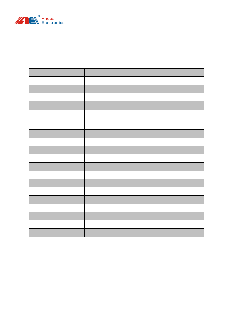
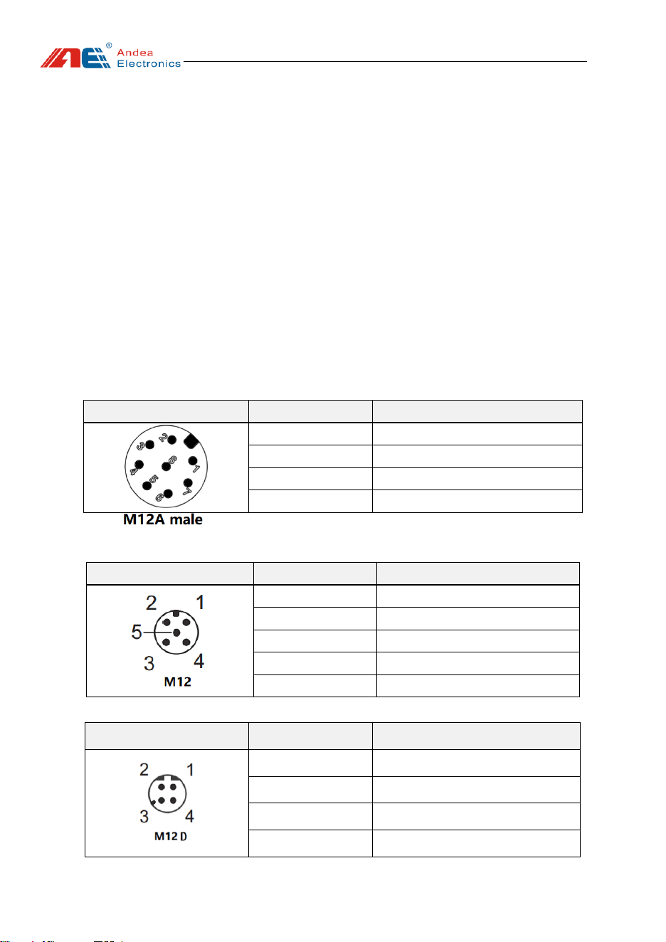
This product has three communication ports:
⚫ Port 1 is an industrial plug 8pin male (M12A): 6 I/O ports (8pin, 2 isolated
inputs, 4 outputs).
⚫ Port 2 is an industrial plug 5pin male (M12A): RS485 communication port +
power supply.
➢ Baud rate: 19200
User manual
Guangzhou Andea Electronics Technology Co., Ltd. 1/9
http://www.gzandea.com
➢ Bit length: 8 bits
➢ Stop bit: 1 bit
➢ Parity: Even
⚫ Port 3 is an industrial plug 4pin male (M12D): Ethernet communication
port.
The default IP address of the reader is 10.168.1.222, and the default port is
502.
ARU5321M&T-S04 product can be powered by DC 24V (10~30V) or 48V POE
(46~54V, IEEE802.3af). The product supports both power supply methods, but only one
method needs to be selected for actual use.
ARU5321M&P-S04, ARU5321M&E-S04, and ARU5321M&I-S04products are
powered by DC 24V (10~30V).
Table 2 Pin Definition of Port 1
Port 1
Pin (8-pin male)
Digital Input/Output
1,2
Input 1-2
3,4,5,6
Output 1-4
7
COM
8
GND
Table 3 Pin Definition of Port 2
Port 2
Pin (5-pin male)
Connection (Communication Port +
Power)
1
24V DC
2
A(485)
3
0V
4
B(485)
5
GND
Table 4 Pin Definition of Port 3
Port 3
Pin (4-pin male)
Connection (Ethernet Port)
1
TD+
2
RD+
3
TD-
4
RD-
User manual
Guangzhou Andea Electronics Technology Co., Ltd. 1/9
http://www.gzandea.com
3. Communication Connection
3.1. Ethernet Connection Instructions
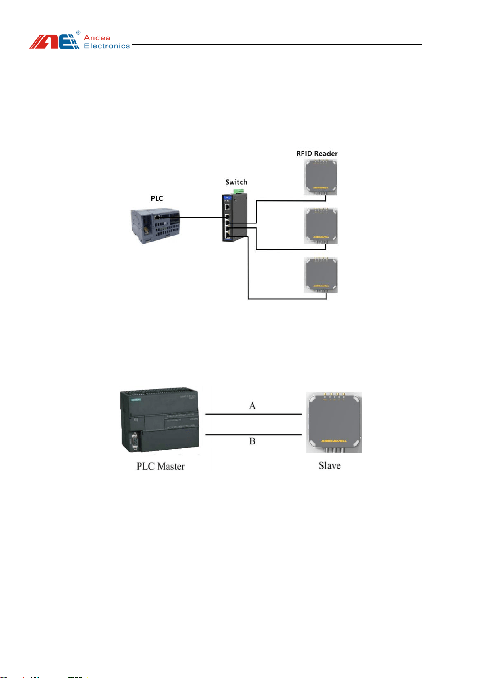
The ARU5321M&x-S04 reader and commonly used PLC can be networked
through the Ethernet switch.
Figure 2 Product working network topology
3.2. Serial Port Connection Instructions
When a single ARU5321M&x-S04 reader is connected to a PLC via the RS485
serial port, direct connection is sufficient.
Figure 3 ARU5321M&x-S04 stand-alone connection to PLC(RS485)
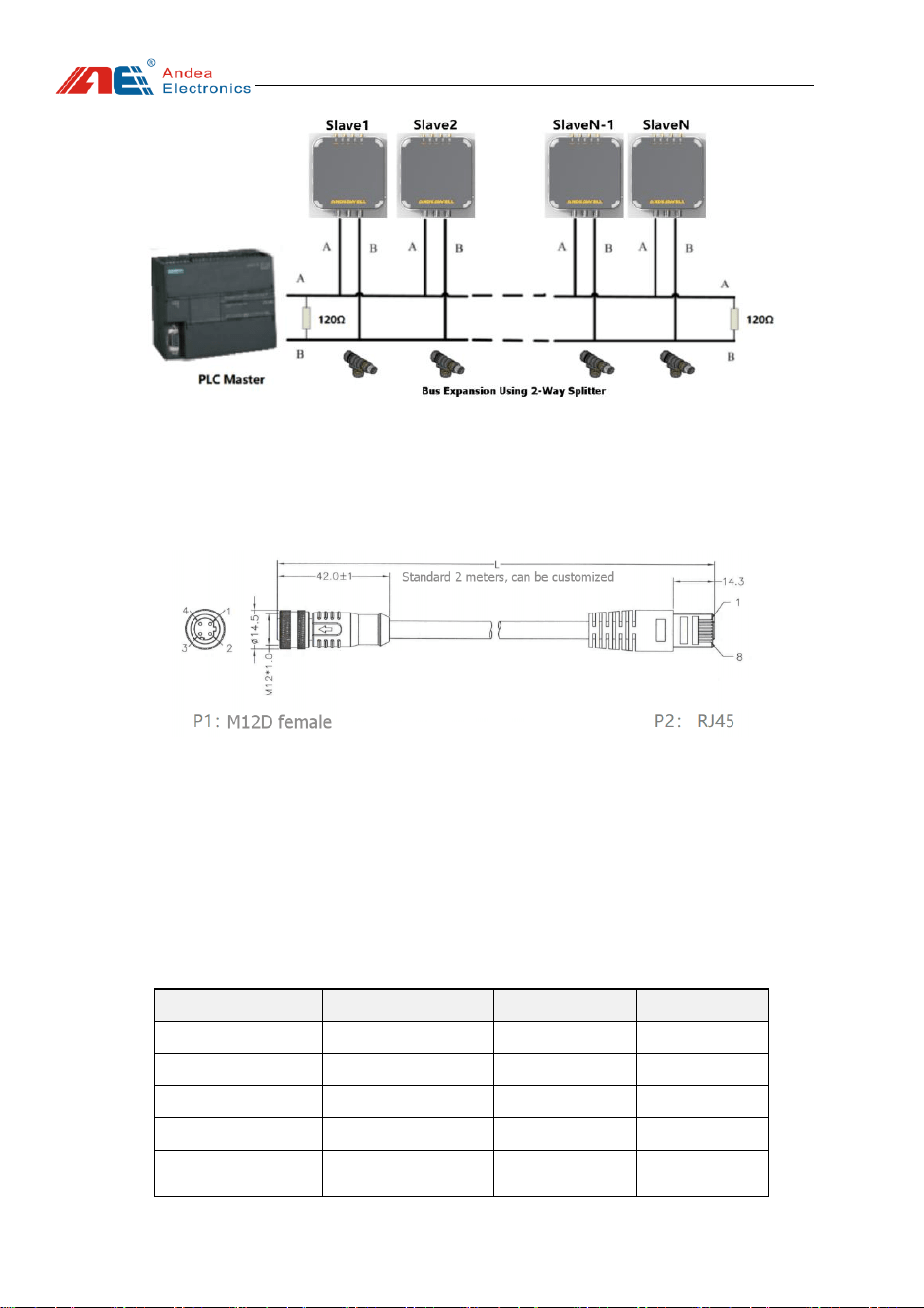
The RS485 bus supports multiple ARU5321M&x-S04 readers to be mounted on
the same bus for multi-machine networking. When multiple readers are mounted on the
bus, 120Ω matching resistors should be connected to the front and rear ends of the bus
to improve communication reliability.
User manual
Guangzhou Andea Electronics Technology Co., Ltd. 1/9
http://www.gzandea.com
Figure 4 ARU5321M&x-S04multi-machine 485 bus connection
3.3. Connector Instructions
3.3.1. Ethernet Cable
Figure 5 Industrial Ethernet cable
When the product uses POE power supply, the ARU5321M&x-S04 only needs one
industrial Ethernet cable. To improve communication reliability and system EMI
performance, it is recommended to use CAT5E standard industrial Ethernet cable as the
communication cable. The theoretical communication distance is up to 100 meters, and
it is recommended to use within 80 meters in actual applications.
Table 5 Port Connections
P1 (Reader)
P2 (Router)
Definition
Color
1
1
TD+
Orange-white
3
2
TD-
Orange
2
3
RD+
Green-white
4
6
RD-
Green
Metal shielding
mesh
Metal shielding
mesh
Signal
shielding mesh
User manual
Guangzhou Andea Electronics Technology Co., Ltd. 1/9
http://www.gzandea.com
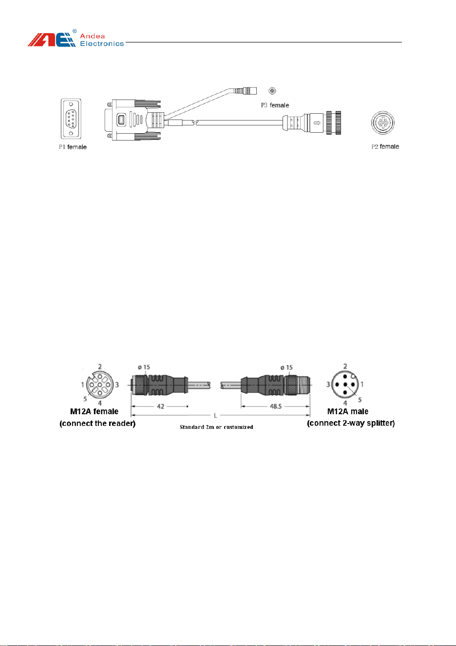
3.3.2. One-to-Two Debugging Cable
Figure 6 One-to-Two Debugging Cable (Optional)
The female connector P2 (M12A female) of this cable can be directly connected to
Port 2 (M12A 5PIN male) of the ARU5321M&x-S04. The female connector P3 can be
connected to a DC2.1 male adapter power supply (10-30V), and the female connector
P1 is an RS485 interface for communication with a computer.
3.3.3. DC Power Supply and Serial Communication Cable
One end (M12A female connector) of the DC 24V power supply cable is connected
to the reader, and the other end (M12A male connector) is directly connected to the
power supply; or a 2-way splitter can be used to power multiple readers with one power
supply. The 5-core cable contains 2 power wires (1, 3), 2 RS485 communication wires
(2, 4), and 1 ground wire (5).
Figure 7 DC power supply, serial communication cable
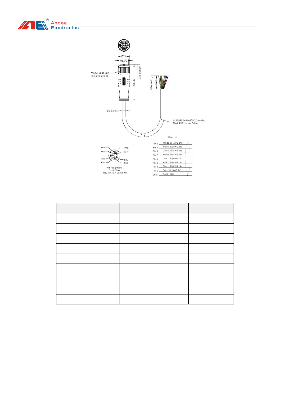
3.3.4. IO Separation Cable
The 8-core cable of power supply and communication IO separation cable contains
2 digital input wires (1, 2), 4 digital output wires (3, 4, 5, 6), 1 common wire (7), and 1
ground wire (8).
User manual
Guangzhou Andea Electronics Technology Co., Ltd. 1/9
http://www.gzandea.com
Figure 8 IO Separation Cable (optional)
Table 6 Port Connections
P1 (Reader)
Cable Color
Definition
1
Red
DI 1
2
Blue
DI 2
3
White
DO 1
4
Brown
DO 2
5
Gray
DO 3
6
Pink
DO 4
7
Yellow
COM+
8
Green
GND
Metal shielding mesh
Metal shielding mesh
PE
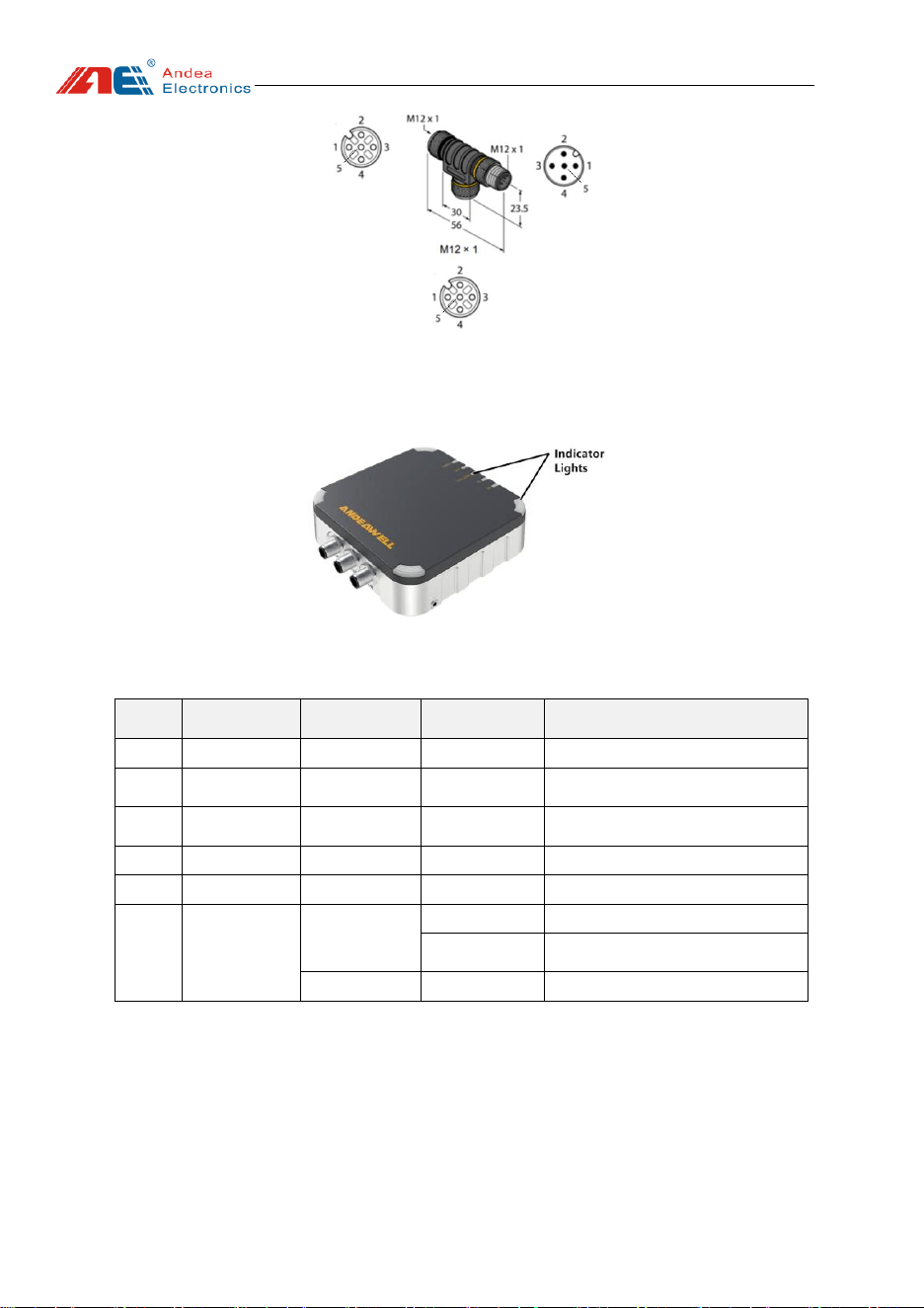
3.3.5. 2-Way Splitter
The power supply and RS485 communication bus can be expanded by connecting
through a 2-way splitter:
User manual
Guangzhou Andea Electronics Technology Co., Ltd. 1/9
http://www.gzandea.com
Figure 9 2-way splitter (optional)
4. Indicator Light Description
Figure 10 Reader Indicator Lights
Table 7 Reader indicator lights description
No.
LED
Color
State
Instructions
1
POWER
Blue
Always on
Reader power is on
2
LAN
Yellow-green
Blinking
Network communication with host
computer
3
UART
Green
On
RS485 communication with host
computer
4
DI
Green
On
Input level detected
5
DO
Green
On
Output circuit level output
6
Four-corner
ambient light
White
Always on
Power-on standby state
Blinking
The corresponding antenna port
detects the RFID tag
Red
Always on
Device fault warning
5. Technical Support
➢ Download link for development data and testing
http://www.gzandea.com/download.php
➢ Call for equipment debugging and technical support
Mobile phone: 138 0251 4535

Caution: The user is cautioned that changes or modifications not
expressly approved by the party responsible for compliance could void
the user's authority to operate the equipment.
This device complies with Part 15 of the FCC Rules. Operation is
subject to the following two conditions: (1) this device may not cause
harmful interference, and (2) this device must accept any interference
received, including interference that may cause undesired operation.
NOTE: This equipment has been tested and found to comply with the
limits for a Class B digital device, pursuant to Part 15 of the FCC Rules.
These limits are designed to provide reasonable protection against
harmful interference in a residential installation. This equipment
generates, uses and can radiate radio frequency energy and, if not
installed and used in accordance with the instructions, may cause
harmful interference to radio communications. However, there is no
guarantee that interference will not occur in a particular installation.
If this equipment does cause harmful interference to radio or television
reception, which can be determined by turning the equipment off and on,

the user is encouraged to try to correct the interference by one or more of
the following measures:
-- Reorient or relocate the receiving antenna.
-- Increase the separation between the equipment and receiver.
-- Connect the equipment into an outlet on a circuit different from that to
which the receiver is connected.
-- Consult the dealer or an experienced radio/TV technician for help.
FCC Radiation Exposure Statement:
This equipment complies with FCC radiation exposure limits set forth
for an uncontrolled environment. This transmitter must not be co-located
or operating in conjunction with any other antenna or transmitter.
(* The product should not be used in contact with the human body. The
warning is as follows)
This equipment should be installed and operated with a minimum
distance of 20cm between the radiator and your body.

Guangzhou Andea Electronics Technology Co., Ltd.
Address: 11th Floor, Building C2, Lian Dong U-Valley, Yihang
Intelligent Technology Park, No.29, Bishan Street, Huang Pu District,
Guangzhou, Guangdong, China.
Zip code: 510705
Website: http://www.gzandea.com