1
IMPORTANT: READ THESE INSTRUCTIONS CAREFULLY BEFORE STARTING INSTALLATION OR USE.
Robert H. Peterson Co. • 14724 East Proctor Avenue • City of Industry, CA 91746
INSTALLER: Leave these instructions with consumer.
CONSUMER: Retain for future reference.
SAFETY AND WARNING CODES
Robert H. Peterson Co. • 14724 East Proctor Avenue • City of Industry, CA 91746
WARNINGS AND SAFETY CODES
GAS GRILL CART BASE
INSTALLATION
AND OWNER’S MANUAL
660-SC24 & 790-SC24
DANGER:
IF YOU SMELL GAS:
• Shut o gas to the appliance.
• Extinguish any open ame.
• Open cabinet door.
• If odour continues, keep away from the
appliance and immediately call your gas
supplier or the re department.
WARNING:
• Do not store or use gasoline or other
ammable liquids or vapours in the vicinity
of this base or any other appliance.
• An LP cylinder not connected for use shall
not be stored in the vicinity of this base or
any other appliance.
WARNING:
Improper installation, adjustment, alteration,
service, or maintenance can cause injury or
property damage. For proper installation,
refer to the installation instructions. For
assistance or additional information, consult
a qualied professional service technician,
service agency, or the gas supplier.
ONLY TO BE USED OUTDOORS
CODE AND SUPPLY REQUIREMENTS: Installation must
conform with local codes or, in the absence of local codes,
with either the National Fuel Gas Code, ANSI 2223.1/NFPA
54, or the Natural Gas and Propane Installation Code, CSA
B149.1, or the Propane Storage and Handling Code, CSA
B149.2, as applicable.
When installed to this base:
The outdoor cooking gas appliance and its individual
shut-o valve must be disconnected from the gas supply
piping system during any pressure testing of that system
at test pressures in excess of
1
/2 psi (3.5 kPa).
The outdoor cooking gas appliance must be isolated from
the gas supply piping system by closing its individual
manual shut-o valve during any pressure testing of the
gas supply piping system at test pressures equal to or
less than
1
/2 psi (3.5 kPa).
IN ADDITION TO THIS DOCUMENT, ALL
INFORMATION INCLUDING WARNINGS,
SAFETY CODES, GUIDELINES, CLEARANCES
AND REQUIREMENTS OUTLINED IN THE GRILL
OWNER'S MANUAL MUST BE FOLLOWED.
THIS BASE WILL GET HOT WHEN THE
INSTALLED APPLIANCE IS IN USE.
CART BASE MODELS
660-SC24 790-SC24
Compatible Units
2024 models to current:
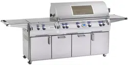
E660i Grill & Griddle, A660i Grill & Griddle, 4600 & 5660 Pizza Oven
2024 models to current:
E790i Grill, A790i Grill
REV 0 - C - 2508250840
L-C2-724
(790-SC24 Model shown)

2
CONTENTS
GETTING STARTED
INSTALLATION, OPERATION, AND SAFETY INFORMATION �����������������������������������������������������������������������������3
APPLIANCE INSTALLATION REQUIREMENTS ����������������������������������������������������������������������������������������������������3
GAS SAFETY INFORMATION ����������������������������������������������������������������������������������������������������������������������������������4
WARNING �������������������������������������������������������������������������������������������������������������������������������������������������������������4
WHEN USING PROPANE GAS ����������������������������������������������������������������������������������������������������������������������������������4
WHEN USING NATURAL GAS ����������������������������������������������������������������������������������������������������������������������������������4
INSTALLATION SAFETY GUIDELINES�����������������������������������������������������������������������������������������������������������������������4
OPERATING THE UNIT SAFELY AND CORRECTLY ���������������������������������������������������������������������������������������������4
SAFE USE & MAINTENANCE OF PROPANE GAS CYLINDERS ���������������������������������������������������������������������������5
MODEL SPECIFICATIONS ���������������������������������������������������������������������������������������������������������������������������������������7
FIRE MAGIC GRILL CART BASE REPLACEMENT PARTS LIST ��������������������������������������������������������������������������8
INSTALLATION
INSTALLATION ���������������������������������������������������������������������������������������������������������������������������������������������������������9
PREPARE CART BASE ���������������������������������������������������������������������������������������������������������������������������������������������9
PREPARE APPLIANCE ����������������������������������������������������������������������������������������������������������������������������������������� 10
INSTALL POWER SUPPLY ������������������������������������������������������������������������������������������������������������������������������������ 10
INSTALL APPLIANCE TO CART BASE ��������������������������������������������������������������������������������������������������������������������� 11
CONNECT GAS SUPPLY ��������������������������������������������������������������������������������������������������������������������������������������� 12
LEAK TEST ��������������������������������������������������������������������������������������������������������������������������������������������������������� 13
RE-INSTALL DRIP TRAY (if applicable) �������������������������������������������������������������������������������������������������������������������� 13
RE-INSTALL DRAWERS ���������������������������������������������������������������������������������������������������������������������������������������� 13
INSTALL FOLDING SHELVES �������������������������������������������������������������������������������������������������������������������������������� 13
CONNECT TO POWER ����������������������������������������������������������������������������������������������������������������������������������������� 13
USE, CARE, & SERVICE
FOLDING SHELF OPERATION ����������������������������������������������������������������������������������������������������������������������������� 14
SOFT-CLOSE DOOR HINGE ADJUSTMENTS ������������������������������������������������������������������������������������������������������ 14
DRAWER REMOVAL ��������������������������������������������������������������������������������������������������������������������������������������������� 14
SERVICING AND CLEANING ������������������������������������������������������������������������������������������������������������������������������� 14
GETTING STARTED
REV 0 - C - 2508250840
L-C2-724
3
WARNING: NEVER cover more than 75% of the cooking surface with griddles, pots, or pans. Overheating will occur,
and burners will not perform properly when combustion heat is trapped below the cooking surface.
IMPORTANT: IN THE EVENT OF A GREASE FIRE, IMMEDIATELY SHUT OFF THE MAIN GAS VALVE TO THE UNIT.
ALLOW THE FIRE TO EXTINGUISH ITSELF. KEEP AT A SAFE DISTANCE. A THOROUGH INSPECTION BY A QUALIFIED
PROFESSIONAL SERVICE TECHNICIAN SHOULD BE CONDUCTED BEFORE FUTURE USE OF YOUR UNIT. THE
SERVICE TECHNICIAN WILL CHECK THE SYSTEM FOR GAS LEAKS AND WILL CHECK ALL ELECTRICAL WIRING
FOR DAMAGE. ALL GAS LEAKS AND WIRING MUST BE REPAIRED PRIOR TO FUTURE USE.
1. Wear gloves and use extreme caution whenever installing and handling this product and its
accessories as certain components have sharp edges that can cause personal injury.
2. The outdoor appliance and surrounding area MUST remain clear of ammable substances such as
gasoline, yard debris, wood, etc. Maintain a minimum horizontal clearance of 18" (in all directions)
from combustible materials/items.
3. This cart base must be installed so that the vent openings on the cabinet remain clear and
free at all times. See the GAS SAFETY INFORMATION section.
4. When using propane gas: the propane cylinder, regulator, and rubber hose must be in a
location not subject to temperatures above 125° F (51° C).
5. The in-line gas valve or gas cylinder valve must always be shut OFF when the unit is not in use.
6. Do not store combustible materials in the cabinet directly beneath the appliance.
BEFORE INSTALLING THE APPLIANCE TO THE CART BASE:
IMPORTANT!
YOU MUST READ the appliance owner's manual for all
INSTALLATION REQUIREMENTS and GAS-SUPPLY PLUMBING
REQUIREMENTS.
APPLIANCE INSTALLATION REQUIREMENTS
INSTALLATION, OPERATION, AND SAFETY INFORMATION
4
WHEN OPERATING THE GAS APPLIANCE, ALL INSTRUCTIONS AND WARNINGS
MUST BE OBSERVED. FAILURE TO DO SO MAY RESULT IN A FIRE OR EXPLOSION
CAUSING PROPERTY DAMAGE, BODILY INJURY, OR DEATH.
Every time you use the appliance, make sure that:
1. The area around the base and appliance are clear and free from combustible materials, gasoline and
ammable vapours and liquids.
2. There is no blockage of the airow through the vent openings located on the cabinet.
3. The hose is inspected (if applicable). See SAFE USE & MAINTENANCE OF PROPANE-GAS CYLINDERS
section.
DO NOT store any combustible materials, gasoline, and any other ammable vapours/liquids in the vicinity of
the base and appliance. Provide adequate clearance for servicing and operation.
WARNING
The appliance MUST be installed and operated according to the information below.
FAILURE TO PROPERLY VENT THE BASE CABINET MAY RESULT IN A FIRE OR EXPLOSION CAUSING
PROPERTY DAMAGE, BODILY INJURY, OR DEATH.
A leaking gas connection or valve unintentionally left open will create a hazard.
WHEN USING PROPANE GAS
• Propane gas (also known as L.P. gas) is heavier than air and will accumulate or pool in an inadequately
vented enclosure or recessed area.
• If a pool of propane gas is ignited, an explosion will occur. Adequate venting at the oor level of the cabinet
eliminates this danger.
• DO NOT store a spare propane-gas cylinder in or near this cart base.
WHEN USING NATURAL GAS
• Natural gas is lighter than air and will accumulate at the top of an inadequately vented enclosure.
• If an accumulation of natural gas is ignited, an explosion will occur. Adequate venting at the top of the cabinet
eliminates this danger.
INSTALLATION SAFETY GUIDELINES
THIS BASE MUST BE INSTALLED SO THAT THE VENT OPENINGS ON THE CABINET REMAIN CLEAR
AND FREE AT ALL TIMES.
The gas cylinder, regulator, and rubber hose must be in a location not subject to temperatures above
125° F (51° C).
IF A PROPANE CYLINDER IS INSTALLED INSIDE OF THE BASE CABINET, THE GUIDELINES FOUND IN THE
SAFE USE & MAINTENANCE OF PROPANE GAS CYLINDERS SECTION of the appliance owner's manual
MUST BE FOLLOWED.
GAS SAFETY INFORMATION
OPERATING THE UNIT SAFELY AND CORRECTLY
5
IMPORTANT FOR YOUR SAFETY
READ AND FOLLOW ALL WARNINGS PROVIDED WITH THE PROPANE-GAS CYLINDER.
When operating this appliance with a propane-gas cylinder, these instructions and warnings MUST be observed.
FAILURE TO DO SO MAY RESULT IN A SERIOUS FIRE OR EXPLOSION.
CYLINDER/CONNECTOR REQUIREMENTS
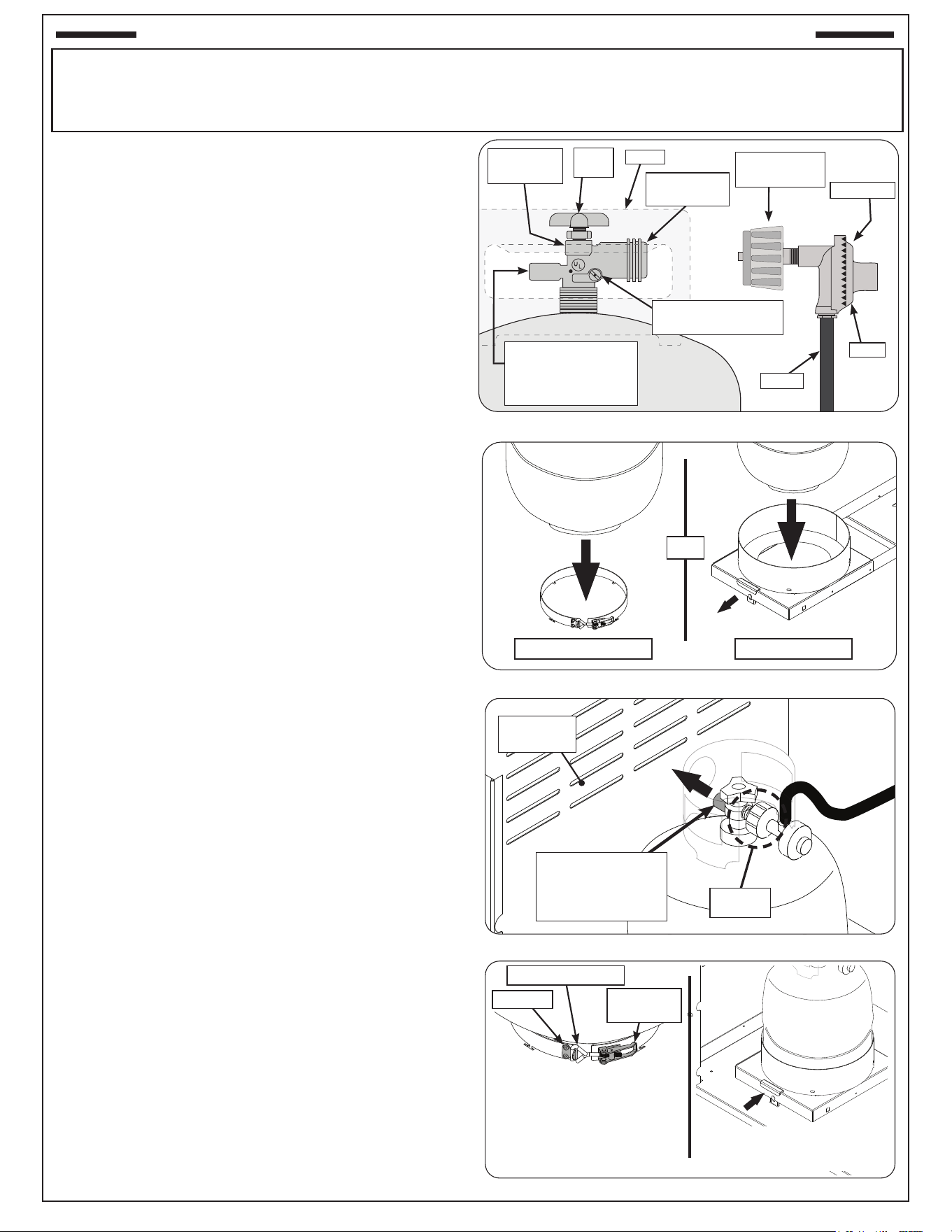
a. Propane-gas cylinders, valves, and hoses must be
maintained in good condition and inspected before each use
of appliance. They must be replaced if there is any visible
damage. If hose is cut or shows excessive abrasion or wear,
it must be replaced before using appliance (see e.).
b. This unit, when used with a cylinder, should be connected
to a standard 5-gallon (20 lb.) propane-gas cylinder
equipped with a listed overlling prevention device. The
device has been required on all cylinders sold since
October 1,1998, to prevent overlling.
c. Cylinder dimensions should be approximately 12" (30.5
cm) in diameter and 18" (45.7 cm) high. Cylinders must
be constructed and marked in accordance with the U.S.
Department of Transportation (D.O.T.) Specications for
LP-Gas Cylinders, or the Standard for Cylinders, Spheres,
and Tubes for Transportation of Dangerous Goods and
Commission, CAN/CSA-B339, as applicable.
d. The cylinder used must include a collar to protect the
cylinder valve. The cylinder supply system must be
arranged for vapour withdrawal. See Fig. 5-1.
e. When used with a cylinder, the gas supply system must
be used with a pressure regulator. The pressure regulator
and hose assembly (not supplied) used must match the
specication for Type I by ANSI Z 21.58/CGA 1.6 and
must comply with UL 144 as a part of the self-contained
LP gas supply system (see Fig. 5-1).
f. The propane-gas cylinder valve must be equipped with
a cylinder connection device, described as Type I in the
standard dened in paragraph e. above. This device is
commonly described as an Acme thread coupler.
g. If the cylinder comes with a dust plug, place it on the
cylinder valve outlet whenever the cylinder is not in use.
Only install the type of dust cap on the cylinder valve outlet
that is provided with the cylinder valve. Other types of caps
or plugs may result in leakage of propane.
COUPLER OPERATION
To connect the regulator/hose assembly to the propane-
gas cylinder valve tting: Press the hand nut on the regulator
over the Acme thread tting on the cylinder valve. Turn the
hand nut clockwise to engage the threads and tighten until
snug. The use of pliers or a wrench should not be necessary.
Only cylinders marked “propane” may be used.
To disconnect: Turn the hand nut counterclockwise until
detached (Fig. 5-1).
Fig. 5-1 Type I Acme thread coupler
QCC Type 1
valve
Pressure relief valve
for vapour withdrawal
(point toward vent
openings)
Brass Acme
thread tting
Hand
wheel
Hand nut with
Acme thread
Liquid level indicator
(optional)
Hose
Regulator
Vent
Collar
Fig. 5-2 Place cylinder
Fig. 5-3 Position for proper vapour withdrawal
Fig. 5-4 Lock cylinder in place
Fig. 5-1 Type I Acme thread coupler
QCC Type 1
valve
Pressure relief valve
for vapour withdrawal
(point toward vent
openings)
Brass Acme
thread tting
Hand
wheel
Hand nut with
Acme thread
Liquid level indicator
(optional)
Hose
Regulator
Vent
Collar
Connect
here
(OR)
Tank collar w/ latch Sliding tank tray
Ventilation
louvers
Point pressure
relief valve toward
louvers for vapour
withdrawal
Lift handle Lift handle
and and
pull tray pull tray
outwardoutward
Slide tray back into cabinet Slide tray back into cabinet
and push latch down to lock and push latch down to lock
in placein place
Bracket
Pull-latch-screw
Pull-latch-
handle
Position pull-latch-screw hook
over bracket. Snap pull-latch-
handle closed. Ensure collar is
holding cylinder securely. (The
pull-latch-screw can be adjusted
to loosen or tighten tension.)
SAFE USE & MAINTENANCE OF PROPANE GAS CYLINDERS
6
Important: Before using the unit, and after each time
the cylinder is removed and reattached,
check the hose for wear (see a.) and check
all connections for leaks. Turn o the unit
valves and open the main cylinder valve,
then check connections with soapy water.
NEVER USE A FLAME TO CHECK FOR
LEAKS. Repair any leaks before lighting
the unit.
CAUTION: Always turn the propane cylinder main
valve o after each use, and before moving
the unit and cylinder or disconnecting the
coupling. This valve must remain closed
and the cylinder disconnected while the
appliance is not in use, even though the gas
ow is stopped by a safety feature when the
coupler is disconnected.
Carefully inspect the hose assembly each time before
the gas is turned on. A cracked or frayed hose must be
replaced immediately.
If the appliance is stored indoors, the cylinder must be
disconnected and removed. Disconnected cylinders must
be stored outdoors, out of the reach of children, with
threaded valve plugs tightly installed, and must not be
stored in a building, garage, or any other enclosed area.
FOR YOUR SAFETY
A. DO NOT store a spare propane-gas cylinder under
or near this appliance.
B. NEVER ll the cylinder beyond 80-percent full.
C. IF THE INFORMATION IN a. AND b. IS NOT
FOLLOWED EXACTLY, A FIRE CAUSING DEATH
OR SERIOUS INJURY MAY OCCUR.
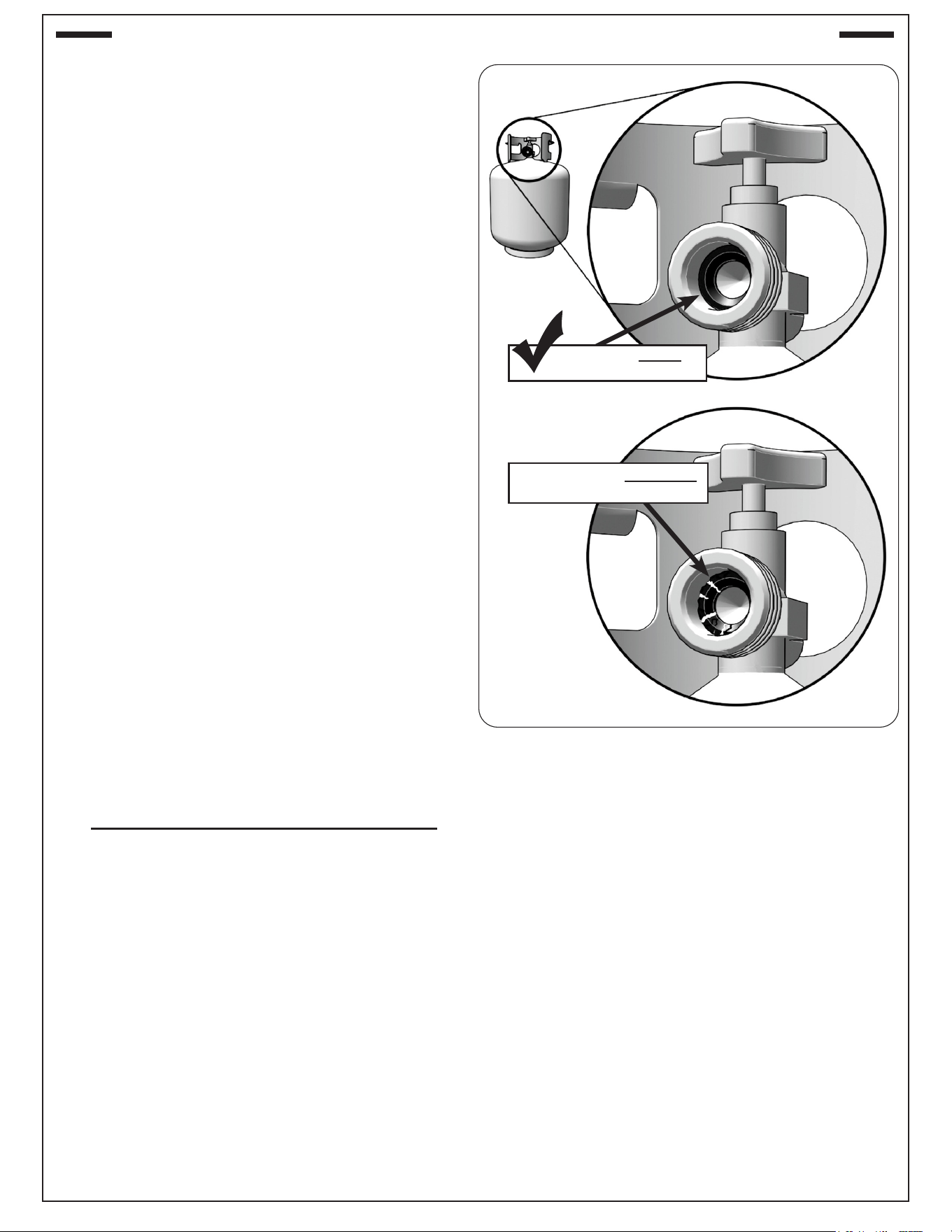
D. CGA 791 connections on LP gas cylinders: The
cylinder face elastomeric face seal element on
these devices could, over time, show marked and
visible damage or deterioration that might cause a
leak even with the connection tightened. A visual
inspection for the seal must be carried out every time
a LP gas cylinder is replaced or relled. Any LP gas
cylinder showing signs of damage or deterioration
as illustrated in Fig. 6-1, including visible cracks and
pitting, must be replaced.
Fig. 6-1 Inspect rubber seal
Example of GOOD
RUBBER SEAL
Example of DAMAGED
RUBBER SEAL
X
SAFE USE & MAINTENANCE OF PROPANE GAS CYLINDERS (Cont.)
7
F
B
A
C
Model
Height Width Depth
Floor to top
of shelf
(A)
Left to right Front to back
Cart base
(B)
(with shelves)
Cart
base
(F)
Maximum
outer
(G)
Up
(C)
Down
(D)
1 Up / 1 Down
(E)
660-SC24 37
1
/2" 34
1
/8" 64
1
/4" 44
1
/4" 54
1
/4" 27" 44
3
/4"
790-SC24 37
1
/2" 39
3
/4" 70" 50" 60" 27" 44
3
/4"
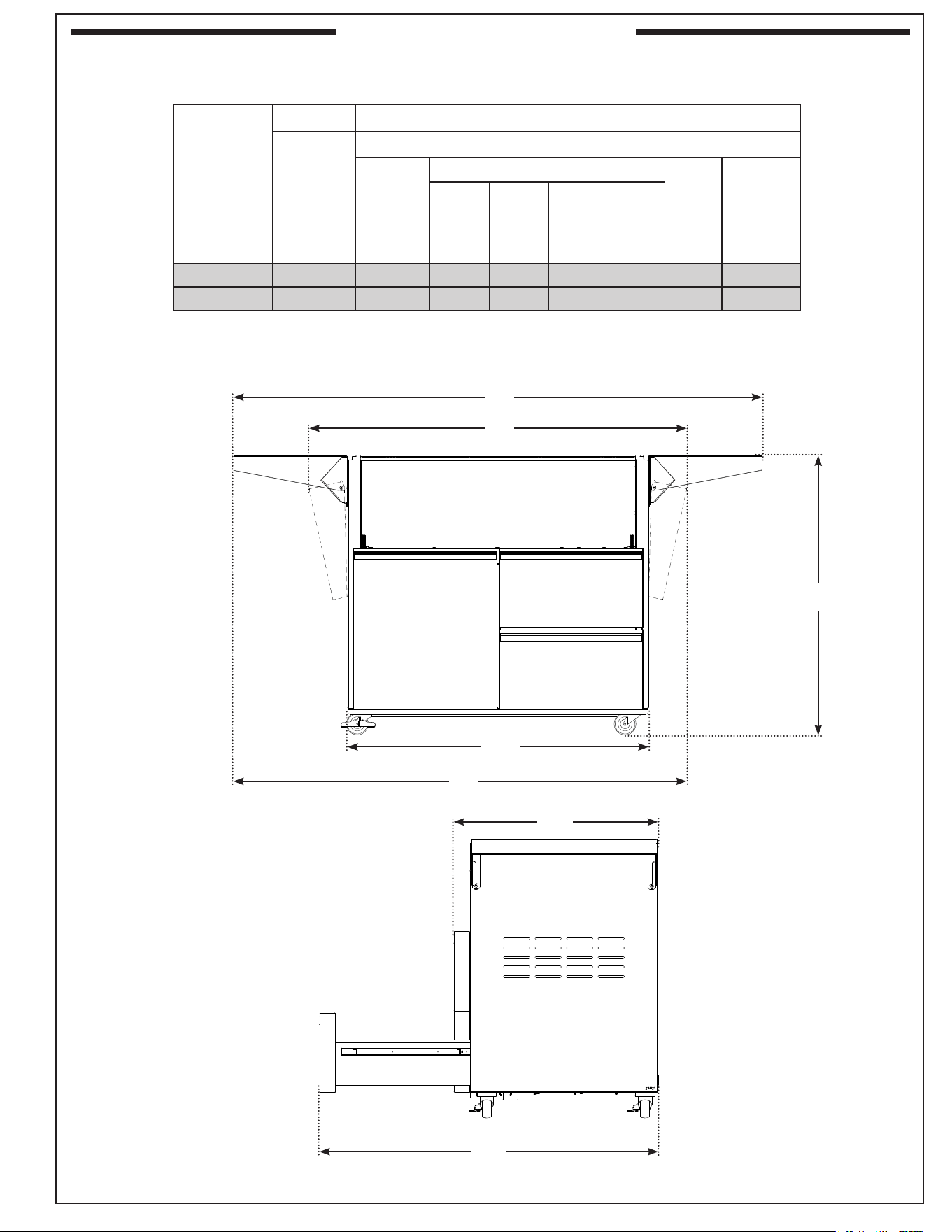
Table 3 - Cart Base Dimensions
MODEL SPECIFICATIONS
D
E
G
8
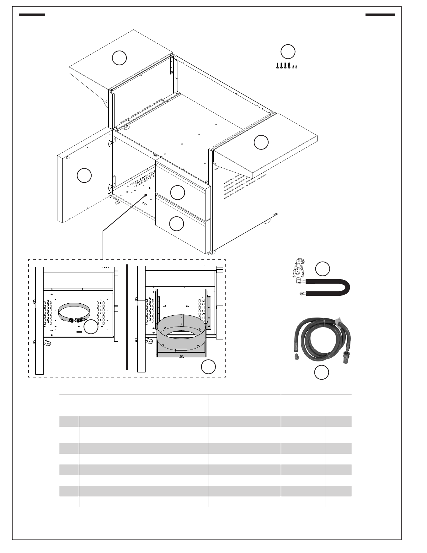
FIRE MAGIC GRILL CART BASE REPLACEMENT PARTS LIST
660-SC24 790-SC24
Item Description Part No. Qty. Part No. Qty.
1.
Folding shelf (w/ hardware) 24336-24 2 24336-24 2
2.
Mounting screw pack
(4)
1
/4"-20 x
5
/8" bolt, (2) #10 x
1
/2" hex screw
MS-3 1 MS-3 1
3.
Propane tank collar w/ latch 5110-35 1 5110-35 1
4. Propane tank sliding tray *
24336-36 1 24336-36 1
5.
Cabinet door w/ soft-close hinges 24394-50 1 24394-50 1
6.
Drawer w/ soft-close slides 24394-53 2 24389-53 2
7. Propane regulator hose *
5110-15 1 5110-15 1
8. Natural gas / Remote LP quick disconnect hose *
5110-03 1 5110-03 1
* Optional, sold separately
1
1
5
6
6
3
2
G
7
8
*
*
4
*
9
INSTALLATION
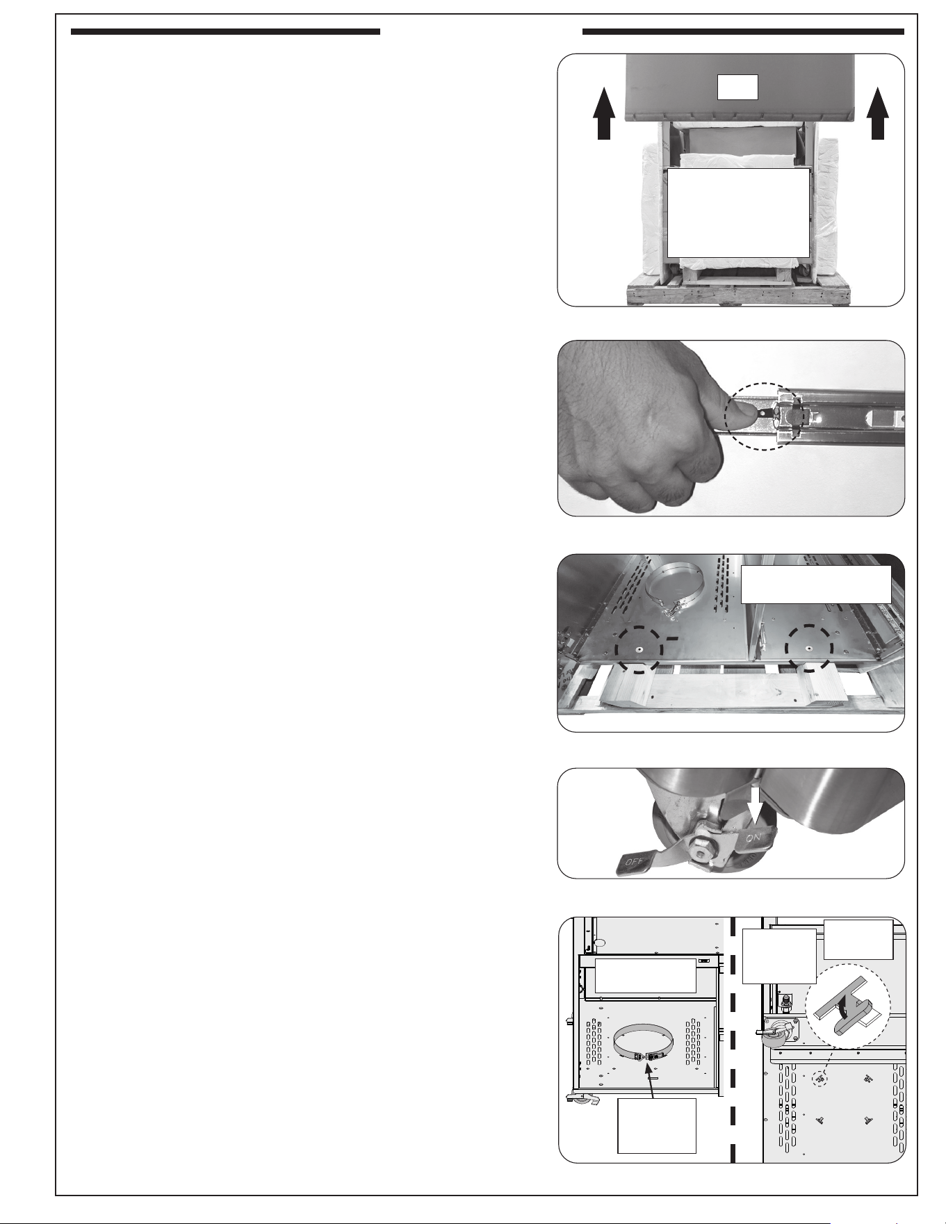
PREPARE CART BASE
Prepare Location
Prepare a at, level surface capable of supporting the weight of
the appliance with cart base and ensure it is conveniently located
near the gas supply source if applicable.
Unpack Cart Base
1. Remove the bottom staples from the perimeter of the pallet
and (with two people) lift the top box upward and o. See
Fig. 9-1.
2. Remove all protective foam pieces, the accessory box, and
any other loose items.
3. Remove the top and bottom drawers:
a. Pull the top drawer outward completely until the slides
stop.
b. Release the drawer from the drawer slides by pressing
the black lever down on the right side, and up on the left
side and pull the drawer free from the slides. See Fig. 9-3.
c. Repeat this process for the bottom drawer.
Note: Do not re-attach the drawers at this point, set them aside
for later installation.
4. Open the cabinet door. Using a Phillips head screwdriver,
remove the two front mounting screws and washers to detach
the cart base from the pallet. See Fig. 9-3.
5. Lift cart base from pallet and place in designated area for
installation.
Lock Wheel Casters
Important: Ensure the casters are locked securely when
installing the appliance to the cart base.
To lock a caster, press down on the side of the lever with the
word "ON" stamped on it until it stops and the caster will not turn.
See Fig. 9-4.To unlock, press down on the side stamped "OFF."
Install Sliding L.P. Tank Tray (if applicable)
If this option was purchased, removal of the existing propane
tank collar will be required before installing the tank tray.
1. Using pliers, bend the tabs straight and guide them through
the slots.
• This process is easiest done if the cart base is gently
rested on its back on a soft protected surface.
• Conrm that the latch is unfastened during this process
to ensure the collar becomes pliable for removal.
2. Once the collar is removed, follow the instructions packed
with the tank tray to install it to the cart base.
Fig. 9-4 Lock wheels
Fig. 9-1 Unpack cart base
Fig. 9-2 Remove drawers
Fig. 9-3 Remove two front screws/washers
Fig. 9-5 Remove tank collar (if applicable)
• Remove staples
• Lift o box
• Remove foam &
all loose items
(Box)
Remove Phillips
screws and washers
Remove
tank collar
(View from inside
of cabinet)
(Underside
of cart)
Move tabs
through
slots
INSTALLATION
10
INSTALLATION (cont.)
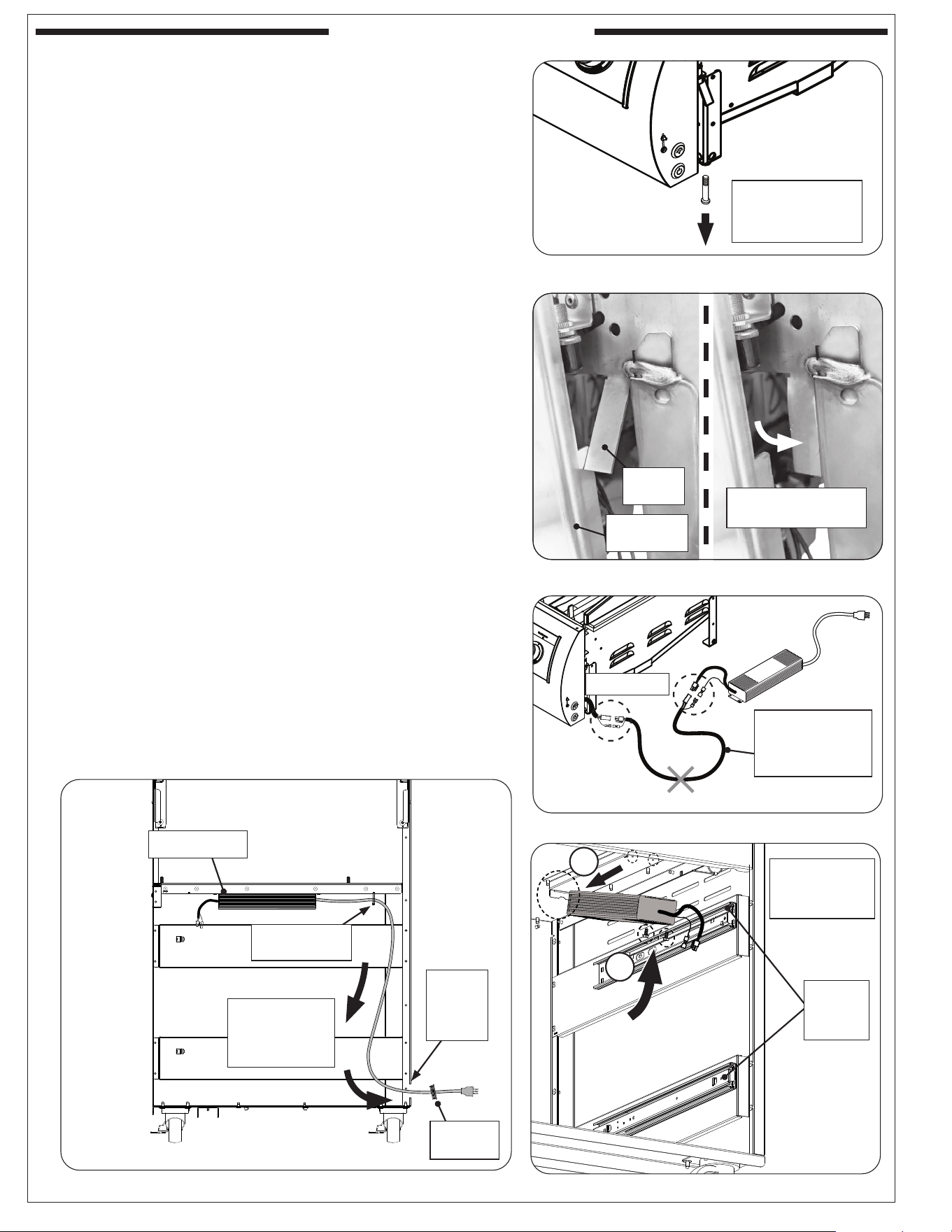
PREPARE APPLIANCE
• Unpack and prepare the appliance for installation per the
owner's manual included with the appliance.
• Remove the drip tray (if equipped).
• Remove the left and right support adjustment bolts
located on the bottom front of the appliance (if applicable).
See Fig. 10-1.
• Using pliers or your hands (wear gloves), bend the face
support tabs inward until they align ush with the sides.
See Fig. 10-2.
• If applicable, cut the zip tie that is securing the wire
harness to the side body.
• If the power supply is pre-connected to the appliance,
disconnect the power supply. Similarly, if a wire harness
extension exists linking between the appliance and power
supply, detach the extension and set it aside as it won't
be used for this installation. See Fig. 10-3.
MOUNT POWER SUPPLY TO CART BASE
1. Insert the rear end of the power supply against the tabs on
the cabinet ceiling ange (Fig. 10-4, A). Use the provided
screws with a athead screwdriver or
5
/16" hex nut driver to
secure the power supply into place. See Fig. 10-4, B.
2. Route the power cord down the right side of the unit between
the slide rail supports and right wall, and feed it through the
hole to exit the cart. See Fig. 10-5.
3. Install the included power cord grommet (with exible
covering).
4. Use a provided zip tie to secure the power cord in place as
shown in See Fig. 10-5. Cut o the excess tie.
Fig. 10-1 Remove adjustment bolts
Remove left
and right front
adjustment bolts
Fig. 10-2 Bend support tabs
Support
tab
(Back lip of
control panel)
Bend tab inward
ush with sides
Fig. 10-3 Detach power supply (if applicable)
Discard harness
extension
(Will not be used for
this installation)
Disconnect
Fig. 10-4 Mount power supply
Fig. 10-5 Route power cord down and out
Secure power
supply to cart
(above drawers)
Ensure
drawers
removed
Route power
cord down and
out through
opening
Zip tie power
cord here
Exit
through
hole in
rear
Install
grommet
Power supply
(Side view of cart)
A
B
11
INSTALLATION (cont.)
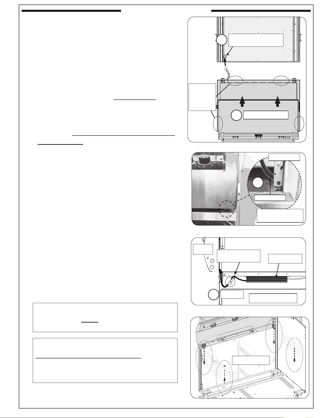
INSTALL APPLIANCE TO CART BASE
It is not required to remove the control panel (or knobs, if
equipped) to install this unit.
DO NOT lift the unit from the control panel when installing.
CAUTION: THE APPLIANCE IS HEAVY AND REQUIRES
TWO OR MORE PEOPLE FOR SAFE HANDLING.
Note: When inserting the appliance, it is advisable to have extra
assistance to keep the cart stable in place.
1. Carefully rest the rear end of the appliance over the cart
opening and begin to slide the unit inward. DO NOT SLIDE
THE UNIT IN COMPLETELY! While installing (Fig. 11-1,
A), be sure to simultaneously route the ex connector
downward through the rounded hole on the front left
portion of the cavity oor. See Fig. 11-1, B.
Note: Only lift the appliance from the locations indicated on
Fig. 11-1. Do not lift the unit from the control panel.
2. While installing, insert the wire harness into the open
cavity on the right side of the cart base. Ensure to route
the wire harness on the left side of the grill front leg while
inserting (see Fig. 11-2, C). Routing the wire hareness on
the right side of the grill front leg will cause pinching and
damage of wiring.
3. Slide in the appliance completely until the back portion of
the unit drops slightly, the hangers are resting evenly on
the cart body, and the unit reaches its full stopping point.
Important: Ensure the wire harness electrical and gas
connections are clear from pinching, undamaged,
and the appliance is completely inserted into the
cart base cavity.
4. Connect the appliance wire harness to the power supply.
See Fig. 11-3, D.
5. Install a provided zip tie as shown in Fig. 11-3 to keep the
electrical connections securely in place.
6. Open the cabinet door. Fasten the four included screws to
the appliance's front and rear legs from inside the cabinet
using a Phillips head screw driver. See Fig. 11-4. Tighten
securely.
Fig. 11-1 Begin appliance installation
Fig. 11-2 Route wire harness
Simultaneously route
ex through hole
Slide unit into cart
Fig. 11-3 Zip tie electrical connections
Fig. 11-4 Secure appliance to cart base
(Top view of cart)
(Top view of appliance)
A
B
Power supply
Zip tie wire
connections here
(Side view of cart)
(Front)
Fasten screws
IMPORTANT:
Lift unit
from these
4 locations
only
Connect
D
IMPORTANT:
THE SCREWS MUST BE USED TO PROPERLY
SECURE THE APPLIANCE TO THE CART BASE.
IMPORTANT:
WALL CLEARANCES MUST BE MET. Refer to the
appliance owner's manual for required clearances as
applicable to your installation. Be sure to measure
from the units hanger (with shelves down) to wall.
Wire harness
Grill front leg
(Control panel
removed for clarity)
C
12
INSTALLATION (cont.)
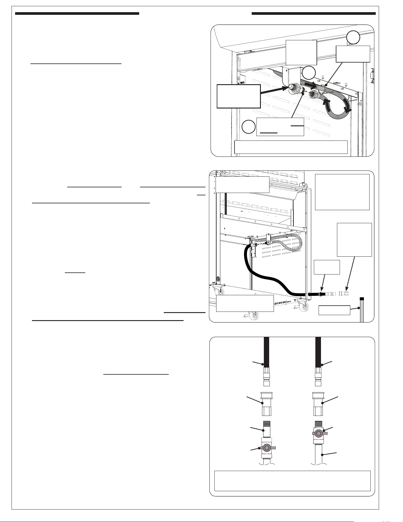
CONNECT GAS SUPPLY
Route the ex connector coming from the appliance to the
adapter that is pre-mounted on the upper left side of the
cabinet interior. Connect the ex connector to the adapter-
end facing the rear of the cabinet. See Fig. 12-1, A & B. Then,
secure the ex hose to the cart body using a provided zip tie
(Fig. 12-1, C).
To Connect To Propane Cylinder:
• A regulator hose assembly designed for L.P. cylinders
is available for purchase. See PARTS LIST and contact
your dealer for ordering information.
• Read the safety warnings and follow the instructions in
the SAFE USE AND MAINTENANCE OF PROPANE
GAS CYLINDERS section, then connect the L.P.
regulator hose to the opposite end of the pre-mounted
adapter. See Fig. 12-1.
To Connect To Natural Or Household Propane Gas Supply:
• Before connecting the gas supply to your appliance,
pressures MUST be tested and MUST NOT exceed
10.5" w.c. for Nat. gas and 13" w.c. for L.P. gas. An
additional regulator may be required.
• Refer to the GAS SUPPLY PLUMBING REQUIREMENTS
section of your appliance owner's manual for all details
on the gas supply and its setup.
• For natural gas models, a quick disconnect hose is
available for purchase and must connect to the pre-
mounted adapter inside the cabinet. For household
propane, an appropriate, C.S.A. approved, exible hose
or similar MUST be purchased to route from the gas
line to the pre-mounted adapter inside the cabinet. The
R.H.P. quick disconnect hose is recommended, and is
discussed and illustrated here. See PARTS LIST and
contact your dealer for ordering information. (If your
setup varies from what is shown here, observe the
National Fuel Gas Code and all local codes.)
1. Turn OFF gas supply at the source.
2. Install a quick disconnect hose or similar (purchased
separately) to the adapter inside the cabinet. (An R.H.P.
quick disconnect hose is recommended - see third bullet
above.) Use a pipe joint compound resistant to all gasses
on all NPT pipe ttings except are ttings. Reference
Fig. 12-2. Then proceed to step 3.
3. Install the included open-hole grommet to the hole in
the rear bottom right of the cabinet, then route the quick
disconnect hose (or similar) out of the hole, and to the
gas supply (see Fig. 12-2).
Note: For quick disconnect hoses, the quick disconnect
female socket will rst need to be detached to allow
the hose to feed through the hole.
4. A shut-o valve is required within 6 feet of the unit and
must be easily accessible.
Connect the quick disconnect female socket to the
shut-o valve OR gas supply (NPT) using a pipe joint
compound resistant to all gasses (see Fig. 12-3). Tighten
securely. Re-attach the hose to the disconnect female
socket.
Fig. 12-2 Flexible hose assembly detail
Fig. 12-3 Connecting to a gas line
Gas supply
(NPT)
NPT-to-NPT
Shut-o valve**
(end of gas
supply)
NPT-to-NPT
Shut-o valve**
(in-line)
Gas supply
(NPT)
Quick
disconnect
female
socket*
Quick
disconnect hose
(or similar)*
coming from
the unit
* R.H.P. quick disconnect hose shown here. Setup may vary.
** Shut-o valve: required, not included, must be within 6 feet
of unit and must be easily accessible.
-OR-
Quick
disconnect
female
socket*
Quick
disconnect hose
(or similar)*
coming from
the unit
Required exible
hose within cabinet
(R.H.P. quick
disconnect hose
shown here)
(Quick disconnect
hose sold separately)
(Grill rear; wall
removed for clarity)
Install
grommet
Gas supply
(Detach quick
disconnect
female socket
to feed hose
through)
Fig. 12-1 Connect appliance ex to adapter
Secure with
zip tie
Connect to rear
facing adapter
(Front)
Route
ex from
appliance
Do not kink ex tube; use wide radius bend to
prevent gas ow reduction and noise/whistling.
A
B
C
GAS SOURCE
CONNECTS
HERE
13
Refer to the appliance owner's manual for any further instructions
required to complete the installation of your appliance.
INSTALLATION (cont.)
LEAK TEST
Turn all burner valves to the OFF position. Turn on the gas
supply, and test at all connections for leaks using a soapy
water solution. If bubbles appear, a leak is present. Turn o the
gas and tighten at all connections. Repeat until no leaks are
present. If a leak persists, turn o the gas supply and contact
the local gas company or dealer. NEVER USE A FLAME TO
CHECK FOR LEAKS.
Once the leak test is complete, turn o the gas supply and
proceed.
RE-INSTALL DRIP TRAY (if applicable)
Reinstall the drip tray to the appliance. For additional information,
refer to the appliance owner's manual.
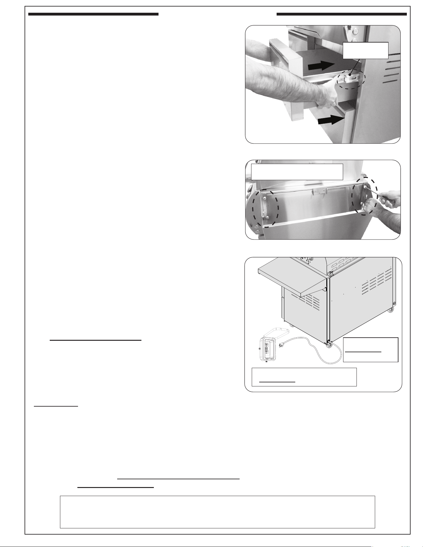
RE-INSTALL DRAWERS
1. Take a drawer and align the left and right side brackets
to the slides.
2. Carefully push the drawer to the closed position. See Fig.
13-1.
3. Open the drawer to verify that is has locked in place.
4. Repeat this process for the second drawer.
INSTALL FOLDING SHELVES
1. Take a folding shelf and carefully align the mounting holes
on the shelf bracket to the holes found on the upper left
body of the cart base.
Note: Take caution to not scratch any stainless steel surfaces
when aligning the shelf.
2. Using the provided Phillips head screws and lock washers
(packaged with drawers), fasten the shelf bracket to the
cart base. See Fig. 13-2. Tighten securely.
Easiest method of install: First fasten the top two holes
of the bracket, set the shelf to the up-position (see next
page for details), then fasten the two bottom holes.
3. Repeat this process for the right side.
CONNECT TO POWER
Connect the power cord to a 120VAC (15 AMP minimum) GFCI
GROUNDED three-wire receptacle (see Fig. 13-3). The GFCI
receptacle must be a WEATHER-PROOF IN-USE COVERED
RECEPTACLE.
WARNING: Electrical Grounding Instructions - This
appliance is equipped with a three-pronged
(grounding) plug for your protection against
shock hazard and should be plugged directly
into a properly grounded three-prong
receptacle. Do not cut or remove the grounding
prong from this plug.
Fig. 13-1 Re-install Drawers
Link brackets
to slides
Fig. 13-2 Install folding shelves
Fig. 13-3 Connect to power
3-wire
GROUNDED cord
from unit
120VAC (15 AMP minimum) GFCI
GROUNDED 3-wire receptacle
(Cart
rear)
Secure shelves with screws
and lock washers
14
USE, CARE, & SERVICE
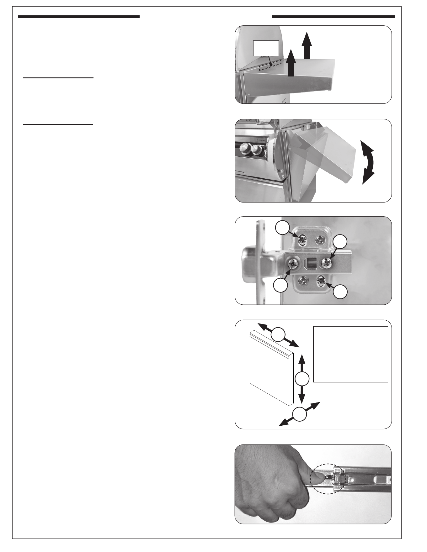
FOLDING SHELF OPERATION
CAUTION: DO NOT place fingers near hinge when
opening or closing.
To lower the shelf: Grasp the middle of the shelf on both
sides and lift upward so that the inner lip of the shelf lifts
out of the locking slot. Then slowly rotate the shelf to the
down position.
To raise the shelf: Grab the shelf bottom-end and raise
to the horizontal position. Lift slightly upward from the
center of the shelf on both sides, allowing the inner lip to
drop down into the locking slot and lock the shelf safely
into position.
SOFT-CLOSE DOOR HINGE ADJUSTMENTS
Both soft-close hinges have three door adjustment
capabilities. See below and reference Fig. 14-3 and Fig.
14-4.
Screw marked "A" adjusts the door left or right. Turn
clockwise to move right and counter-clockwise to move
left, on both hinges.
Screw marked "B" adjusts the door inward or outward.
First loosen screw "B", adjust door as needed, then re-
secure.
Screws marked "C" adjusts the door up or down. First
loosen both "C" screws, adjust door as needed, then
re-secure.
DRAWER REMOVAL
1. Pull the top drawer outward completely until the
slides stop.
2. Release the drawer from the drawer slides by pressing
the black lever down on the right side, and up on
the left side and pull the drawer free from the slides.
See Fig. 14-5.
3. Repeat this process for the bottom drawer.
SERVICING AND CLEANING
Refer to the SERVICING AND CLEANING section of your
appliance owner's manual for all information.
Fig. 14-1 Shelf in upward position
Fig. 14-2 Shelf lowering or raising
Lift upwards
to free from
locking slot
Locking
slot
Fig. 14-5 Remove drawers
USE, CARE, & SERVICE
Fig. 14-4 Door hinge adjustments
A
C
B
Screw A:
adjusts left/right
Screw B:
adjusts inward/outward
Screws C:
adjusts up/down
Fig. 14-3 Door hinge detail
(Door)
A
B
C
C