Icon Legend...............................4
Warnings & Notices.....................5
Platform Construction.................6
Truss Assembly.........................11
Gable Assembly........................18
Door Assembly..........................21
Floor Assembly..........................35
Wall Assembly..........................39
Parts Identifi er..........................47
Shelving Installation..................53
Roof Assembly..........................57
Window Installation...................77
Shutter Installation...................80
Accessory Installation................83
Door Alignment........................85
Shed Anchoring........................88
Cleaning & Care........................91
Registration.........................92
Warranty.................................93
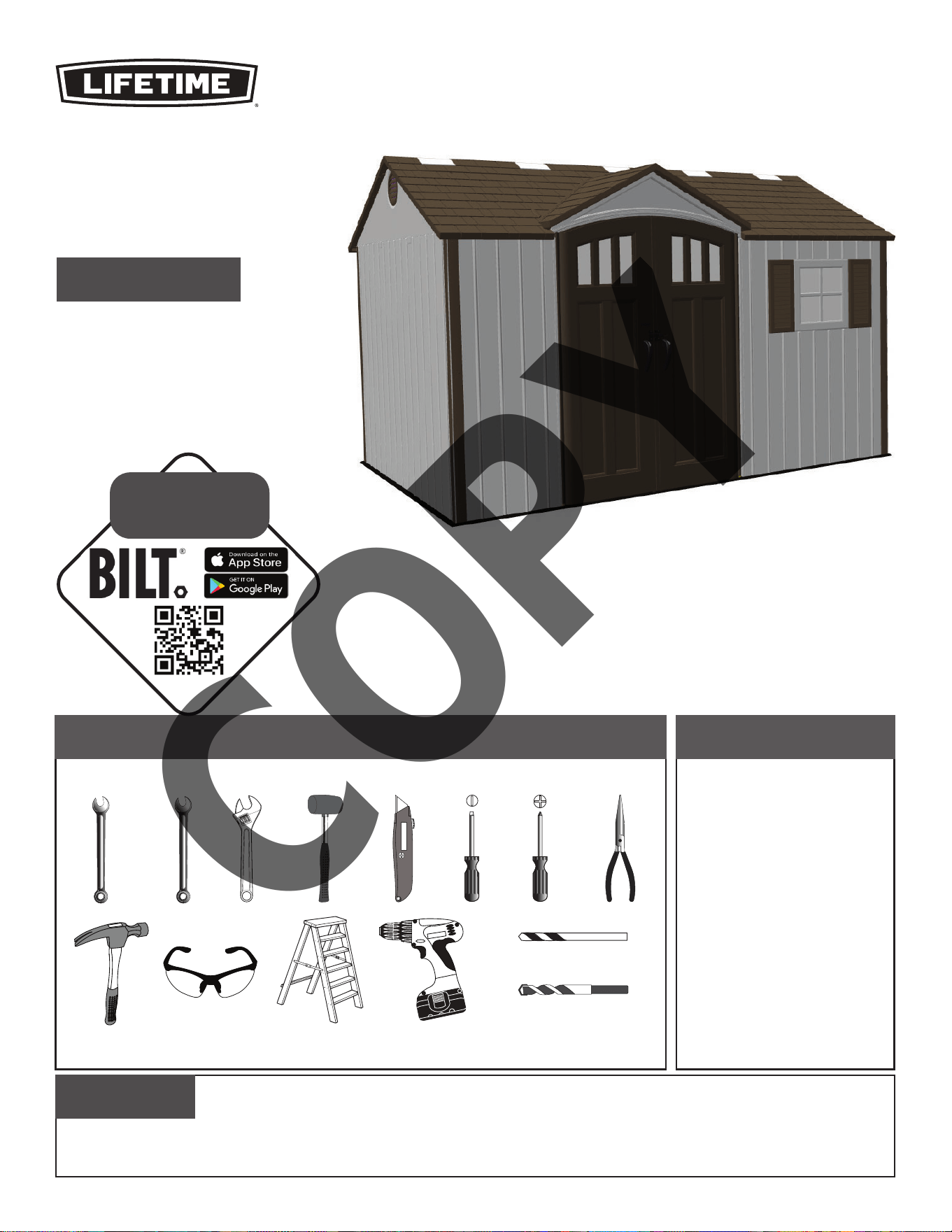
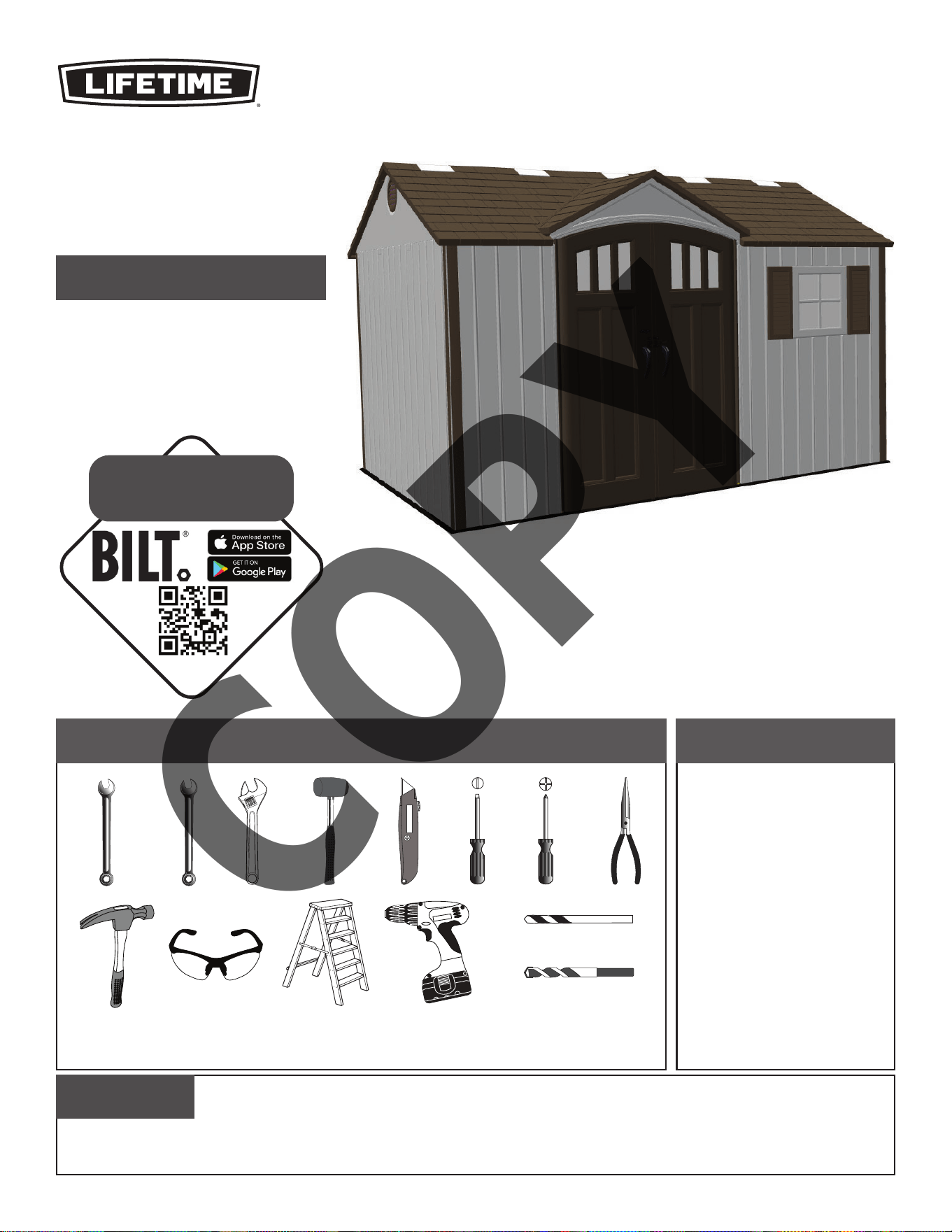
TOOLS REQUIRED TABLE OF CONTENTS
CONTACT LIFETIME CUSTOMER SERVICE:
Call: 1-800-225-3865
7:00 am–5:00 pm (Monday–Friday) MST
and 9:00 am–1:00 pm Saturday MST
Live Chat: www.lifetime.com
(click on “LIVE CHAT” tab)
QUESTIONS?
MODEL# AND PRODUCT ID (both are needed when contacting us)
Model Number: 60223
Product ID:
BEFORE ASSEMBLY:
• Assemble on a level surface
• At least 3 people for setup recommended
Pour le français, voir la page 2. Para el español, ver la página 3.
ASSEMBLY INSTRUCTIONS
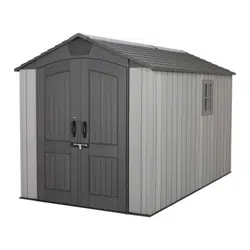
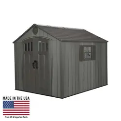
12.5' x 8'
STORAGE SHED
MODEL 60223
7/16" (11 mm)
3/8" (10 mm)
5/16" (8 mm) Wood Drill Bit
5/16" (8 mm) Masonry Drill Bit
3D ANIMATION
OF THE FULL ASSEMBLY
WATCH
SCAN THE
CODE
OR SEARCH
1177581
COPY
Légende des ícônes......................4
Notifi cations et avis.....................5
Assemblage de la plate-forme.......6
Assemblage des fermes..............11
Assemblage des pignons.............18
Assemblage des portes...............21
Assemblage du plancher............35
Assemblage des murs................39
Identifi cateur de pièces..............47
Installation du rayonnage............53
Assemblage du toit....................57
Installation des carreaux.............77
Installation des volets................80
Installation des accessoires........83
Alignement des portes...............85
L’ancrage de l’abri.....................88
Nettoyage et entretien...............91
Enregistrement....................92
Garantie.................................94
OUTILS REQUIS SOMMAIRE
7/16 po (11 mm)
3/8 po (10 mm)
5/16 po (8 mm) Foret à boit
5/16 po (8 mm) Foret à maçonnerie
CONTACTER LES SERVICES À LA CLIENTÈLE LIFETIME
®
:
Composer le 1-800-225-3865
Du lundi au vendredi 7:00 h – 17:00 h (HNR)
et samedi 9:00 h – 13:00 h (HNR)
t’Chat en direct: www.lifetime.com
(cliquer sur la languette « LIVE CHAT »)
QUESTIONS ?
N° DE MODÈLE ET RÉFÉRENCE DU PRODUIT (il faut avoir les deux lors de nous contacter)
N° de modèle : 60223
Référence du produit :
AVANT L’ASSEMBLAGE :
• Assembler sur une surface de niveau
• Nous recommendons, au moins, 3 adultes pour
l’assemblage
For English, see page 1. Para el español, ver la página 3.
INSTRUCTIONS D’ASSEMBLAGE
ABRI EXTÉRIEUR DE
2,4 m x 3,8 m
MODÈLE n° 60223
ANIMATION 3D
DE L'ASSEMBLAGE COMPLET
REGARDER
SCANNER LE
CODE
OU CHERCHER
1177581
COPY
Leyenda de íconos..........................4
Notifi caciones y Advertencias.........5
Ensamble de la plataforma..............6
Ensamble de las cerchas...............11
Ensamble de las fachadas.............18
Ensamble de las puertas...............21
Ensamble del piso.........................35
Ensamble de los muros.................39
Identifi cador de piezas...................47
Instalación de la estantería.............53
Ensamble del tejado......................57
Instalación de las hojas de ventana..77
Instalación de las contraventanas..80
Instalación de los accesorios.........83
Alineación de la puertas................85
Anclaje de la caseta.......................88
Limpieza y cuidado......................91
Regístro...............................92
Garantía.................................95
INSTRUMENTAL REQUERIDO ÍNDICE
7/16 in (11 mm)
3/8 in (10 mm)
5/16 in (8 mm) Broca para madera
5/16 in (8 mm) Broca de albañilería
PONERSE EN CONTACTO CON LOS SERVICIOS DE CLIENTES LIFETIME
®
:
Marcar : 1-800-225-3865
De lunes hasta viernes 7:00 h–17:00 h (MST)
y sábado 9:00 h–13:00 h (MST)
Chat en vivo: www.lifetime.com
(cliquear en la lengüeta «LIVE CHAT»)
¿PREGUNTAS?
MODEL E ID DEL PRODUCTO (se necesitan los dos al contactarnos)
Número de modelo: 60223
ID del producto:
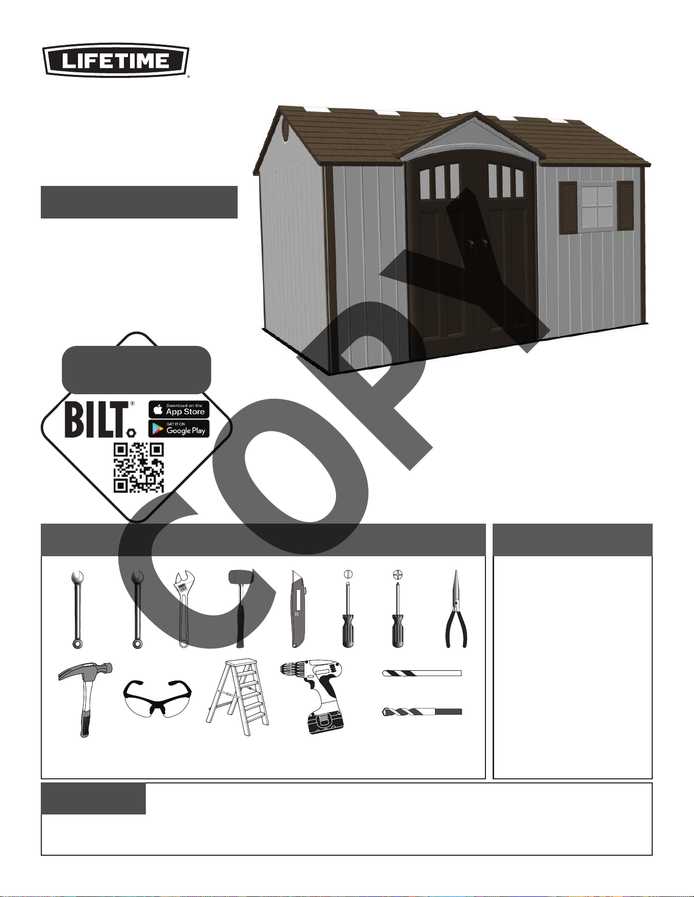
ANTES DEL ENSAMBLE:
• Ensamblar sobre una superfi cie nivelada
• Recomendamos, al menos, 3 adultos para el
ensamble
For English, see page 1. Pour le français, voir la page 2.
INSTRUCCIONES DE ENSAMBLE
CASETA EXTERIOR DE
2,4 m x 3,8 m
MODELO n° 60223
LA ANIMACIÓN 3D
DEL ENSAMBLAJE COMPLETO
MIRAR
ESCANEAR EL
CÓDIGO
O BUSCAR
1177581
COPY
4
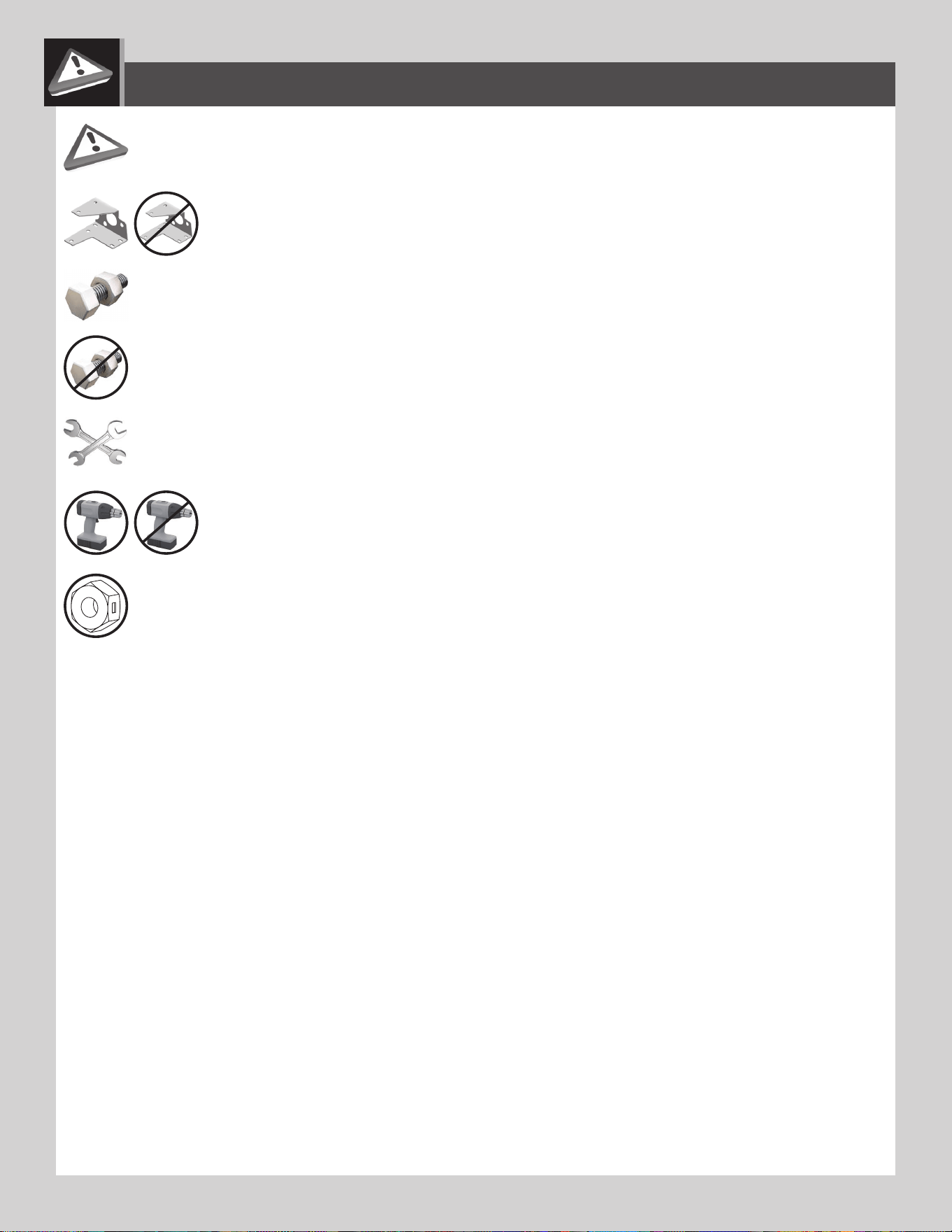
• Indicates the parts/no parts required for a section.
• Indique les pièces à utiliser/qu’aucone pièce n’est requise pour une section.
• Indica las piezas que se usarán/que no necesitan en una sección.
• Indicates special heed should be taken when reading.
• Indique qu’une attention spéciale doit être portée à la lecture.
• Indica que uno debe prestar atención al leer.
• Indicates the hardware to be used for a section.
• Indique la quincaillerie à utiliser pour une section.
• Indica los artículos de ferretería que se usarán para una sección.
• Indicates the tools to be used for a section.
• Indique les outils à utiliser pour une section.
• Indica las herramientas que se utilizarán para una sección.
• Indicates no hardware required for a specifi c page or section.
• Indique qu’aucun matériel n’est requis pour une page précise.
• Indica que no se necesitan los artículos de ferretería para una página específi ca.
• Indicates to use/not use an electric drill for a specifi c step.
• Indique quand utiliser une/que ne pas utiliser de perceuse électrique pour une étape précise.
• Indica la utilización de/que no utilizar un taladro eléctrico para un paso específi co.
ICON LEGEND / LÉGENDE DES ICÔNES / SIGNIFICADO DE LOS ÍCONOS
• These nuts are centerlock nuts. They are designed to be tight; therefore, they will be harder to tighten. Tighten until fl ush
with the metal or plastic.
• Ces écrous sont des écrous de blocage central. Ils sont conçus pour être serrés; de ce fait, ils seront plus diffi ciles à
resserrer. Serrer jusqu’à ce qu’ils soient au ras du métal ou du plastique.
• Estas tuercas son tuercas de bloqueo central. Están diseñadas para estar apretadas; por lo tanto, serán más difíciles de
apretar. Apriételas hasta que estén al ras del metal o plástico.
1220120_B 11/15/2021

5
English:
• Failure to follow these warnings may result in serious injury or property damage and will void warranty.
• To ensure safety, do not attempt to assemble this product without following the instructions carefully.
• Consult all local building codes to verify if the shed requires a building permit.
• Verify the foundation is completely level before assembling the shed.
• Be aware that plastic pieces can be damaged by overtightening the screws. To avoid damage, we strongly recommend
the use of a drill with a low torque setting. A #2 Phillips screwdriver may also be used.
• Three capable adults are required for assembly.
• All who participate in the assembly process should wear safety glasses throughout the assembly.
• If using a ladder during assembly, use extreme caution.
• In heavy snowfall areas, we recommend removing snow from the roof. Remove the snow from the roof when the
depth of snow equals the length of your hand.
• Do not use or store hot objects near the product.
• Proper and complete assembly are essential to reduce the risk of accident or injury.
• When drilling through metal, beware of burrs, shavings and other sharp edges.
• During and after assembly, do not slide or lift the shed by pushing up on the roof. Move the shed by pushing on the
corner panels only.
• We strongly recommend anchoring your shed when it is fi nished. The last section, Shed Anchoring, in this manual shows
the hardware you will need to complete the anchoring. You can fi nd the hardware at your local hardware store.
• Most injuries are caused by misuse and/or not following instructions. Use caution when using this product.
Français :
• Ne pas suivre ces avertissements peut entraîner des blessures graves ou des dommages à la propriété et annulera la garantie.
• Afi n d’assurer la sécurité, ne pas tenter d’assembler ce produit sans suivre attentivement les instructions.
• Consulter tous les codes du bâtiment afi n de vérifi er si l’abri nécessite un permis de construire.
• Vérifi er que la fondation est complètement à niveau avant l’assemblage de l’abri.
• Ne pas oublier que les pièces de plastique peuvent être endommagées en serrant trop les vis. Afi n d’éviter les
dommages, nous recommandons fortement l’utilisation d’une perceuse à faible couple. Un tournevis cruciforme nº 2
peut aussi être utilisé.
• Trois adultes en bonne condition physique sont nécessaires pour l’assemblage.
• Tout ceux qui participent au processus de l’assemblage doivent porter des lunettes de sécurité tout au long de
l’assemblage.
• Si une échelle est utilisée pour l’assemblage, il faut être extrêmement prudent.
• Dans les zones de fortes tombées de neige, il est recommandé de dégager le toit. Enlever la neige du toit quand la
profondeur est égale à la longueur de la main.
• Ne pas utiliser ou entreposer des objets très chauds près de ce produit.
• Un bon assemblage complet est nécessaire pour réduire le risque d’accident ou de blessure.
• En perçant le métal, faire attention aux bavures, copeaux et autre bords aiguisés.
• Pendant et après l’assemblage, ne pas faire glisser ou soulever l’abri en poussant le toit vers le haut. Déplacer l’abri en
poussant les panneaux muraux angulaires seulement.
• Il est fortement recommandé d’ancrer l’abri lorsque l’assemblage est terminé. La dernière section, Ancrage de l’abri, de ce
manuel indique les matériaux nécessaires pour l’ancrage. Les matériaux se trouvent dans la quincaillerie locale.
• La majorité des blessures sont causées par une mauvaise utilisation et/ou le non suivi des instructions. Étre prudent en utilisant ce produit.
Español:
• No seguir estas advertencias puede resultar en lesiones graves o daños a la propiedad y anulará la garantía.
• A fi n de garantizar la seguridad, no intentar ensamblar este producto sin seguir cuidadosamente las instrucciones.
• Consultar todos los códigos de construcción locales para verifi car si la casetao requiere un permiso de construcción.
• Verifi car que el concreto esté nivelado completamente antes de ensamblar la caseta.
• Tener en cuenta que las piezas de plástico pueden dañarse si los tornillos se aprietan de más. A fi n de evitar daños, lo
exhortamos a que use un taladro con función de torque bajo. También puede usarse un desatornillador Phillips no. 2.
• Se necesitan tres adultos para el ensamble.
• Todos los que participen en el proceso de ensamble debe usar anteojos de seguridad durante todo el ensamble.
• Si se usa una escalera durante el ensamblado, es preciso tener cuidado.
• En áreas de nevadas fuertes, recomendamos retirar la nieve del techo. Quitar la nieve del tejado cuando la
profundidad de ella es igual a la longitud de la mano.
• No usar ni guardar objetos calientes cerca del producto.
• El ensamblaje correcto y completo son esenciales para reducir el riesgo de accidente o lesión.
• Al perforar metal, tenga cuidado las rebabas, virutas y otros bordes afi lados.
• Durante y después del ensamblaje, no deslizar ni levantar la caseta par empujar en el tejado. Mover la caseta par
empujar los paneles murales angulares solamente.
• Lo exhortamos a anclar la caseta al terminar el ensamble. La última sección, Anclaje de la caseta, en este manual muestra
el herraje necesaria para terminar el anclaje. Se encuentra el herraje en la ferretería local.
• La mayoría de las lesiones suceden a causa del mal uso y/o por no seguir las instrucciones. Tener precaución al usar este producto.
WARNINGS & NOTICES / AVERTISSEMENTS ET AVIS / ADVERTENCIAS Y AVISOS
6
PLATFORM CONSTRUCTION / CONSTRUCTION DE LA PLATE-FORME / CONSTRUCCIÓN DE LA
PLATAFORMA
1
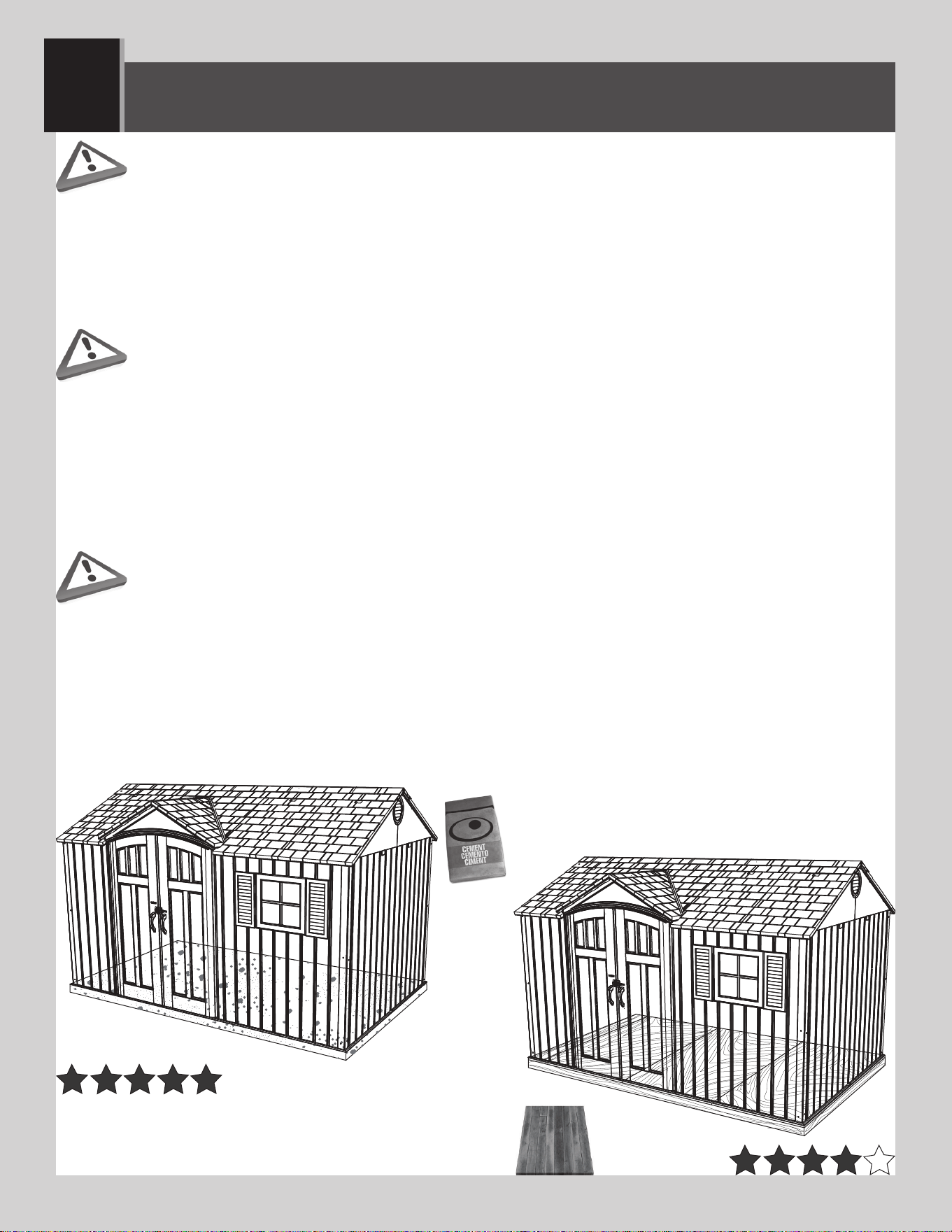
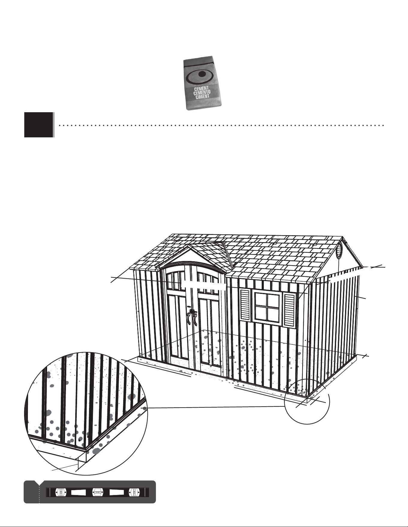
• You must provide a platform on which to assemble your shed. Proper building permit documentation may be
required in your neighborhood. Consult all local building codes prior to assembling the shed. Before beginning
assembly, you must pour or construct a platform. There are two types:
• Concrete
• Wood Frame
Select the type, but know the surface must be leveled and fl at before installation. If the surface is not properly leveled and fl at,
the shed will not assemble correctly. Proper surface leveling will save you time in the long run, so please do not ignore this step.
We recommend a Concrete platform. It will be the most durable and long-lasting choice. The platform you choose must be built above ground in
order to avoid water pooling inside the shed.
• Il faut construire une plate-forme sur laquelle vous devez assembler votre abri. Il est possible que le quartier exige
une documentation visant les permis de construire. Consulter tous les codes du bâtiment locaux, ainsi que les
décrets des villes et comtés, pour vérifi er que la construction de l’abri extérieur n’exige pas un permis de construire.
Avant de commencer l’assemblage, il faut couler ou construire une plate-forme. Il y à deux styles :
• Béton
• Cadre à bois
Sélectionner le style, mais sachez que la surface d’installation doit être de niveau et plate. Si la surface n’est pas correctement
de niveau et plate, l’assemblage de l’abri ne se fera pas correctement. On gagnera du temps sur le long terme grâce à une
surface bien de niveau, alors ne pas négliger cette étape. Nous recommandons une plate-forme en Béton. Ce choix sera le plus durable. La
plate-forme doit être construite au-dessus du sol afi n d’éviter l’accumulation d’eau à l’intérieur de l’abri. Tous le bois d’oeuvre doit être approuvé
pour l’usage à l’extérieur!
• Es preciso construir una plataforma sobre la cual uno puede ensamblar su caseta. Puede suceder que en el
vecindario se requiera la documentación apropiada de un permiso de construcción. Consultar todos los códigos
locales de construcción y los reglamentos de la ciudad y el municipio para asegurarse de que la construcción de
la caseta no requiere un permiso de construcción. Antes de comenzar el ensamble, es necesario verter o construir
una plataforma. Hay dos clases:
• Concreto
• Armazón de madera
Seleccionar la clase, mas sepa que la superfi cie debe estar nivelada y plana antes de comenzar el ensamble. Si la superfi cie
no está nivelada y plana de manera adecuada, la caseta no podrá ensamblarse correctamente. La nivelación de la superfi cie
le ahorrará tiempo de trabajo, por lo tanto, no ignorar este paso. Recomendamos una plataforma hecho de concreto. Será la elección
más perdurable. La plataforma debe ser construida arriba del suelo para evitar el afl ujo de agua dentro de la caseta. ¡Toda la madera debe estar
clasifi cada para el uso externo!
7
X SECTION 1 (CONTINUED) / SECTION 1 (SUITE) / SECCIÓN 1 (CONTINUACIÓN)
1.5 yd
3
(1,15 m
3
)
1
4 in/po (10,2 cm)
!
93 1/2 in/po (2,38 m)
CONCRETE REQUIRED / BÉTON REQUIS / CONCRETO REQUERIDO
CONCRETE PLATFORM / PLATE-FORME EN BÉTON / PLATAFORMA DE CONCRETO
1.1
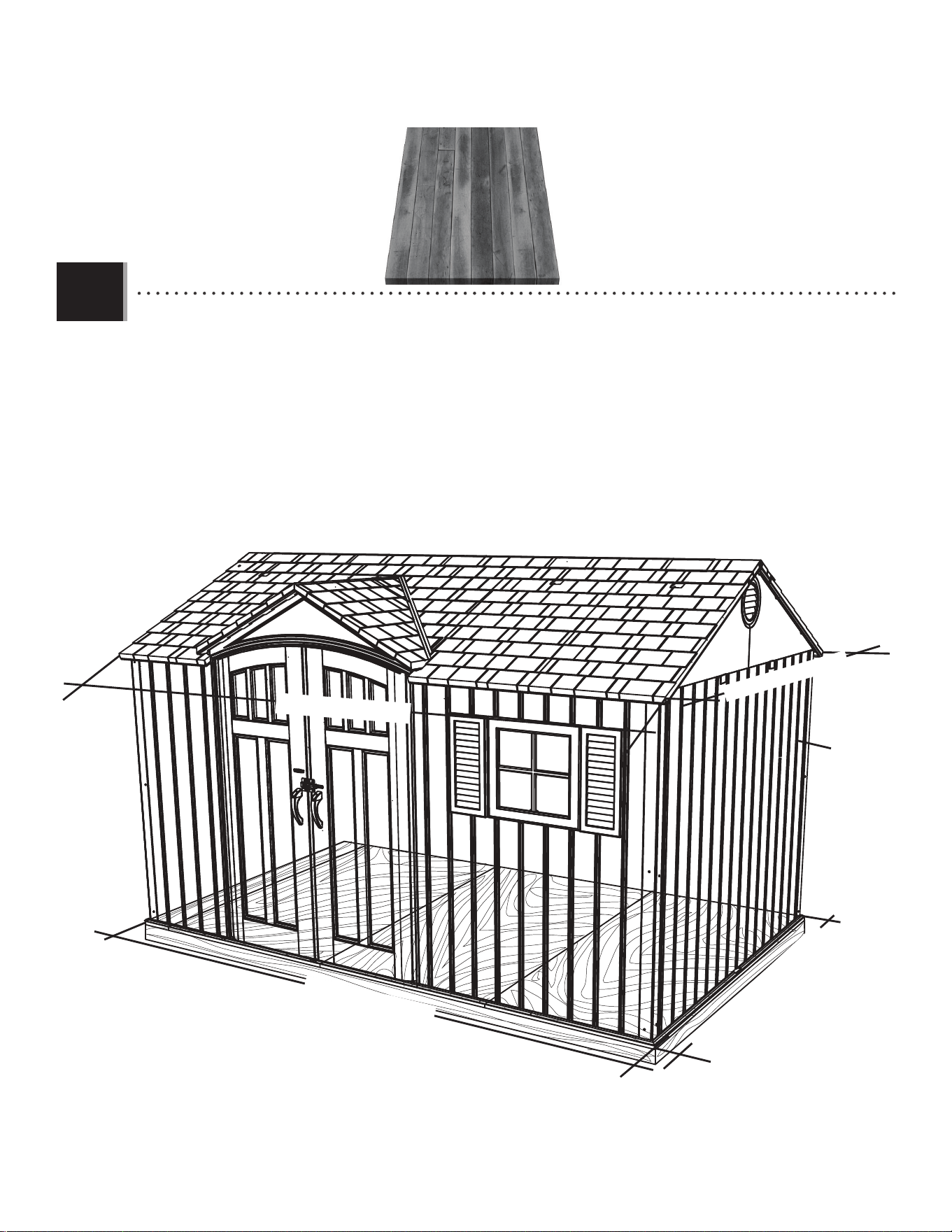
• The concrete should be approximately 4" (10,2 cm) thick. The actual dimensions of the shed, at its widest
and longest points, are 96" x 150" (2,44 m x 1,99 m). Ensure you select a site that will accommodate these
measurements. The fl oor dimensions are a bit smaller than those of the roof; therefore, you will need to builld a level surface of 93
1/2" x 148" (2,38 m 3,76 m).
• Le béton doit être un épaisseur de 10,2 cm (4 po). Les dimensions réelles de votre abri, aux points les plus large
et long, sont 2,44 m x 1,99 m (96 po x 150 po). Veiller sélectionner un site qui accommodera ces dimensions. Les
dimensions du plancher de votre abri sont plus petites que le toit; ensuite, il faut créer une surface nivelée de 2,38 m x 3,76 m (93 1/2
po x 148 po).
• El concreto debe tener, por lo menos, 10,2 cm (4 in) de espesor. Las dimensiones reales de la caseta, a
sus puntos más ancho y largo, son 2,44 m x 1,99 m (96 in x 150 in). Asegurarse de seleccionar un sitio que
acomodará estas medidas. Las dimensiones del piso de la caseta son más pequeñas que el tejado; entonces, es necesario crear
una superfi cie nivelada de 2,38 m 3,76 m (93 1/2 in x 148 in).
150 in/po (3,81 m)
96 in/po (2,44 m)
148 in/po (3,76 m)
8
X SECTION 1 (CONTINUED) / SECTION 1 (SUITE) / SECCIÓN 1 (CONTINUACIÓN)
1
WOOD PLATFORM / PLATE-FORME EN BOIS / PLATAFORMA DE MADERA
1.2
WOOD REQUIRED / BOIS REQUIS / MADERA REQUERIDA
RIDA
93 1/2 in/po (2,38 m)
150 in/po (3,81 m)
96 in/po (2,44 m)
148 in/po (3,76 m)
• All lumber must be rated for outdoor use! The actual dimensions of the shed, at its widest and longest points, are 96"
x 150" (2,44 m x 1,99 m). Ensure you select a site that will accommodate these measurements. The fl oor dimensions
are a bit smaller than those of the roof; therefore, you will need to builld a level surface of 93 1/2" x 148" (2,38 m 3,76 m).
• Tous le bois d’oeuvre doit être approuvé pour l’usage à l’extérieur! Les dimensions réelles de votre abri, aux points les
plus large et long, sont 2,44 m x 1,99 m (96 po x 150 po). Veiller sélectionner un site qui accommodera ces
dimensions. Les dimensions du plancher de votre abri sont plus petites que le toit; ensuite, il faut créer une surface nivelée de 2,38
m x 3,76 m (93 1/2 po x 148 po).
• ¡Toda la madera debe estar clasifi cada para el uso externo! Las dimensiones reales de la caseta, a sus puntos más ancho
y largo, son 2,44 m x 1,99 m (96 in x 150 in). Asegurarse de seleccionar un sitio que acomodará estas medidas.
Las dimensiones del piso de la caseta son más pequeñas que el tejado; entonces, necesitará crear una superfi cie nivelada de 2,38 m
3,76 m (93 1/2 in x 148 in).
9
X SECTION 1 (CONTINUED) / SECTION 1 (SUITE) / SECCIÓN 1 (CONTINUACIÓN)
x8
x36
1
!
2 in/po x 4 in/po x 90 1/2 in/po (5,1 cm x 10,2 cm x 2,30 m) (x11)
2 in/po x 4 in/po x 148 in/po (5,1 cm x 10,2 cm x 3,76 m) (x2)
16d 3 1/2 in/po (16d x 8,89 cm) (x44)
148 in/po (3,76 m)
93 1/2 in/po (2,38 m)
90 1/2 in/po (2,30 m)
16"
16"
16"
16"
16"
16"
16"
16"
16"
148 in/po (3,76 m)
93 1/2 in/po (2,38 m)
90 1/2 in/po (2,30 m)
16 in/po (40,1 cm)
TOOLS, PARTS, AND HARDWARE REQUIRED / OUTILS, PIÈCES, ET QUINCAILLERIE REQUIS / INSTRUMENTAL, PIEZAS, Y HERRAJE
REQUERIDOS
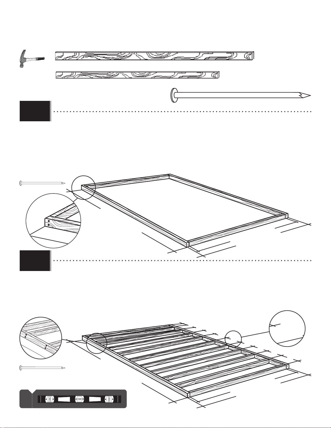
• Ensure all lumber is treated and approved for outdoor use. Build frame to 93 1/2" x 148" (2,38 m x 3,76 m)
(outside dimensions). You can also use the plywood as a fl at surface when building this frame.
• Veiller que votre bois d’œuvre à été traité et approuvé pour l’utilisation à l’extérieur. Contruire un cadre de 2,38
m x 3,76 m (93 1/2 po x 148 po) (dimensions extérieures). On peut aussi utiliser le contreplaqué comme une surface plate
pendant l’assemblage de ce cadre.
• Asegurarse de usar madera tratada y aprobada para el uso externo. Construir el armazón a 2,38 m x 3,76
m (93 1/2 in x 148 in) (dimensiones exteriores). Se puede también usar el contrachapado como una superfi cie plana al
ensemblar este armazón.
• To ensure studs are in the correct location for nailing plywood in the next step, start measuring from the corner
16" (40,1 cm), and then measure from center to center.
• Pour être sûr d’avoir assez de montant pour clouer le contreplaqué dans le prochaine étape, commencer à
mesurer à partir de cette montant 40,1 cm (16 po) vers le centre du deuxième montant. Ensuite, mesurer de
centre à centre pour les montants restants.
• Para asegurarse que los montantes están en las ubicaciones correctas para el contrachapado en el paso
siguiente, comenzar a medir desde el borde del montante hasta el centro del próximo montante 40,1 cm (16 in).
Luego, tomar la medida de centro a centro en los montantes restantes.
WOOD PLATFORM / PLATE-FORME EN BOIS / PLATAFORMA DE MADERA
1.2.1
1.2.2
10
X SECTION 1 (CONTINUED) / SECTION 1 (SUITE) / SECCIÓN 1 (CONTINUACIÓN)
4 in/po x 93 1/2 /po x 3/4 in/po
(10,2 cm x 2,38 m x 19,1 mm)
48 in/po x 93 1/2 in/po x 3/4 in/po
(1,22 cm x 2,38 m x 19,1 mm)
8d 2 in/po (8d 5,08 cm) (x84)
x84
48 in/po x 93 1/2 in/po x 3/4 in/po
(1,22 m x 2,38 m x 19,1 mm) (x3)
1
!
4 in/po x 93 1/2 in/po x 3/4 in/po
(10,2 cm x 2,38 m x 19,1 mm) (x1)
A
B
x30!
Drainage Holes
Agujeros para el drenaje
Trous de drainage
TOOLS, PARTS, AND HARDWARE REQUIRED / OUTILS, PIÈCES, ET QUINCAILLERIE REQUIS / INSTRUMENTAL, PIEZAS, Y HERRAJE
REQUERIDO
!
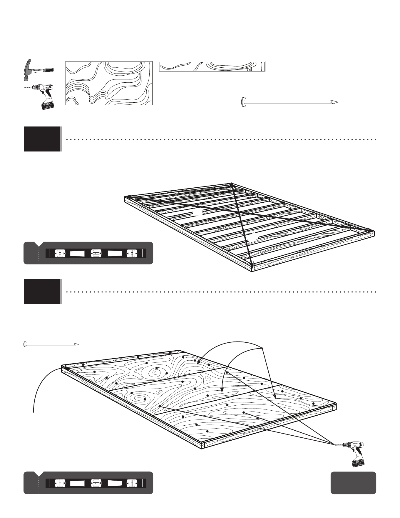
• Square the frame, measuring from corner to corner. Measurement A & B should be about the same length.
• Carrer le cadre en mesurant d’angle à angle. La mesure « A » et « B » doivent être à peu près la même longeur.
• Cuadrar el armazón mediendo de esquina a esquina. La medida «A» y «B» deben ser approximadamente el mismo
largo.
• Using nails, fasten the plywood to the frame. Then, drill 5/16" (8 mm) holes for drainage.
• En utilisant des clous, attacher bien le contreplaqué au cadre. Ensuite, percer des trous de 8 mm pour le
drainage.
• Usando unos clavos, sujetar el contrachapado al armazón. Entonces, taladrar agujeros de 8 mm para el
drenaje.
1.2.3
1.2.4
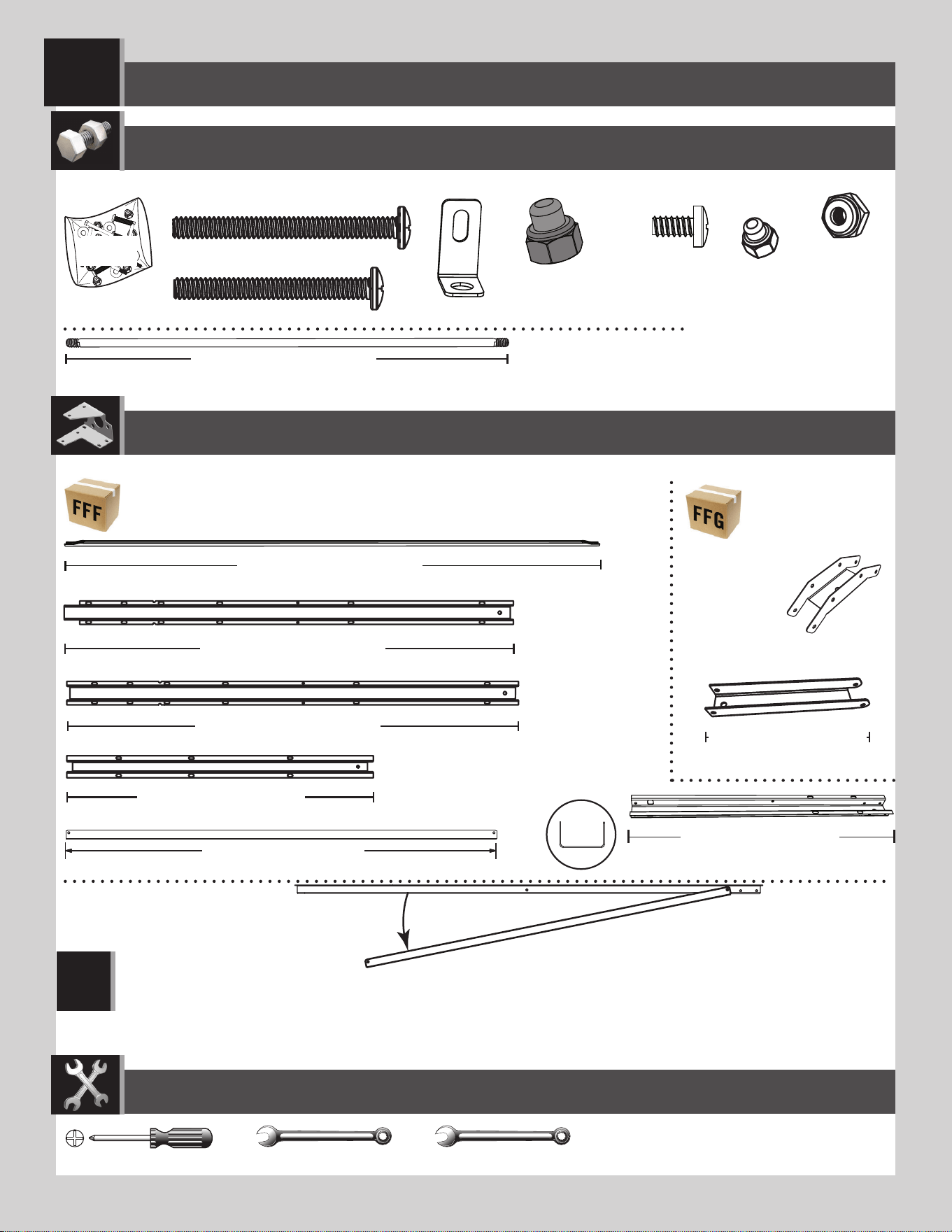
11
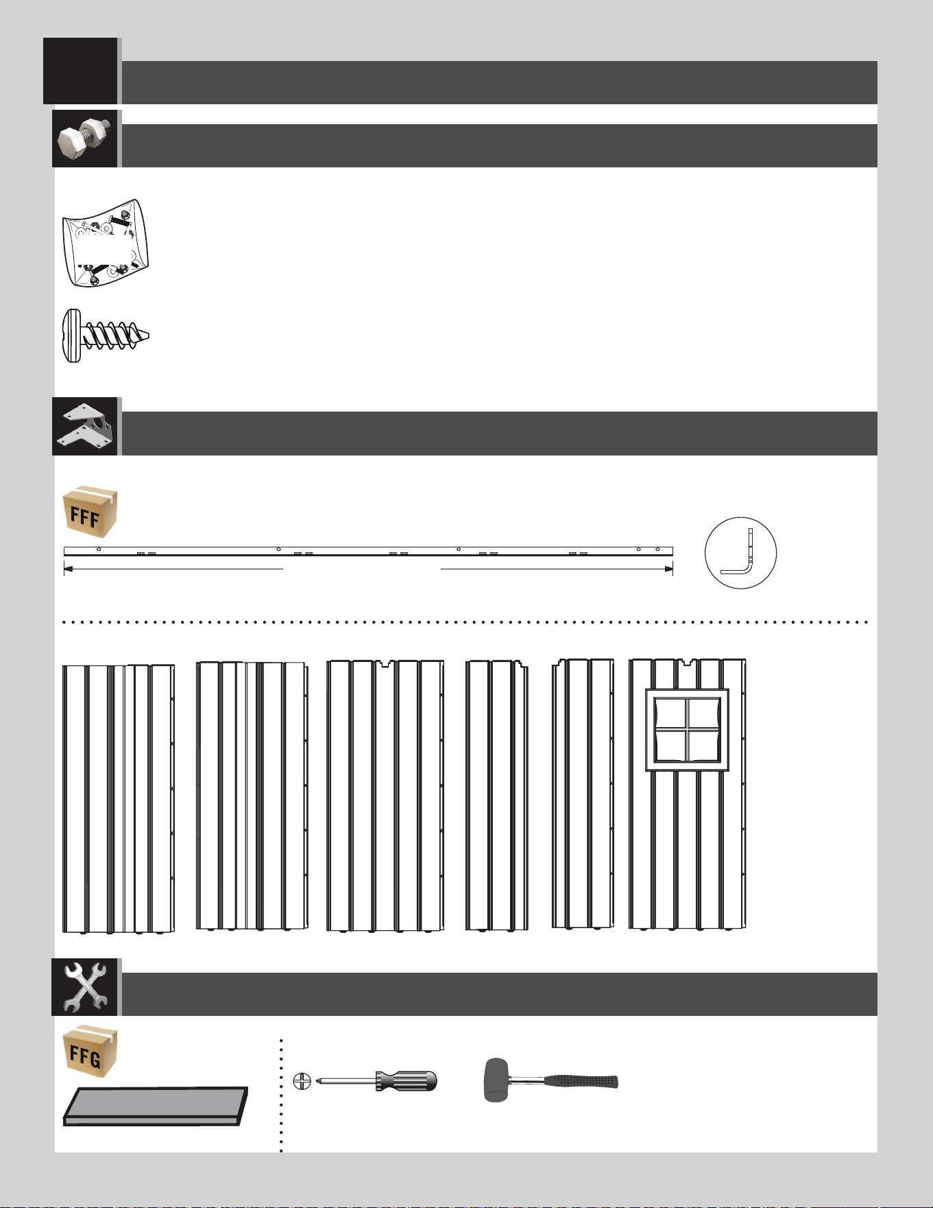
TRUSS ASSEMBLY / ASSEMBLAGE DES FERMES / ENSAMBLE DE LAS CERCHAS
2
11 9/16 in/po (≈29,4 cm)
ADH (x4)
DSR (x5)
AFG (x4)
DSO (x1)
DSM (x1)
DSN (x1)
DSQ (x2)
DSP (x1)
ADY (x16)
ADK (x32)
ADJ (x8)
AIP (x4)
AIP (x4)
8 7/16 in/po (≈21,4 cm)
34 1/8 in/po (≈86,7 cm)
50 9/16 in/po (≈1,28 m)
50 9/16 in/po (≈1,28 m)
48 in/po (≈1,22 m)
DTK (x18)
DTJ (x1)
CXK (x2)
AHT (x1)
7/16 in/po (≈11 mm) (x2) 3/8 in/po (≈10 mm) (x2)
FFX
Metal Parts / Pièces en métal / Piezas de metal
Hardware Bag / Sac de quincaillerie / Bolsa de herraje
TOOLS REQUIRED / OUTILS REQUIS / INSTRUMENTAL REQUERIDO
PARTS REQUIRED / PIÈCES REQUISES / PIEZAS REQUERIDAS
HARDWARE REQUIRED / QUINCAILLERIE REQUISE / HERRAJE REQUERIDO
DSR
AFG
• Sometimes during shipping, the Truss Brace (AFG) slides over the back of the Truss Gutter Channel (DSQ or DSR). The two pieces are the same color. If you think you’re missing a Truss Brace,
check to see if is stuck to the back of the Truss Gutter Channel, and separate the two.
• Durant le transport, parfois le support de ferme (AFG) glisse par-dessus l’arrière du canal de ferme (DSQ ou DSR). Les deux pièces sont du même colour. Si vous pensez que vous n’avez pas de
support de ferme, vérifi ez s’il y a un support de ferme adhéré à l’arrière du canal de ferme, et séparez les deux.
• Durante el transporte, a veces el soporte de cercha (AFG) deslice sobre el dorso del canalon de cercha (DSQ o DSR). Las dos piezas son de la misma color. Si pienza que le falta un soporte de cercha,
verifi que si haya un soporte pegado al dorso del canalón de cercha, y separe las dos.
!
58 1/4 in/po (≈1,47 m)
25 7/8 in/po (≈65,7 cm)
12
TOOLS AND HARDWARE REQUIRED / OUTILS ET QUINCAILLERIE REQUIS / INSTRUMENTAL Y HERRAJE REQUERIDOS
X SECTION 2 (CONTINUED) / SECTION 2 (SUITE) / SECCIÓN 2 (CONTINUACIÓN)
ADK (x8)
AIP
DSR
DSQ
ADK (x4)
DTK (x4)
DTK (x8)
3/8 in/po (x2)
(≈10 mm) (x2)
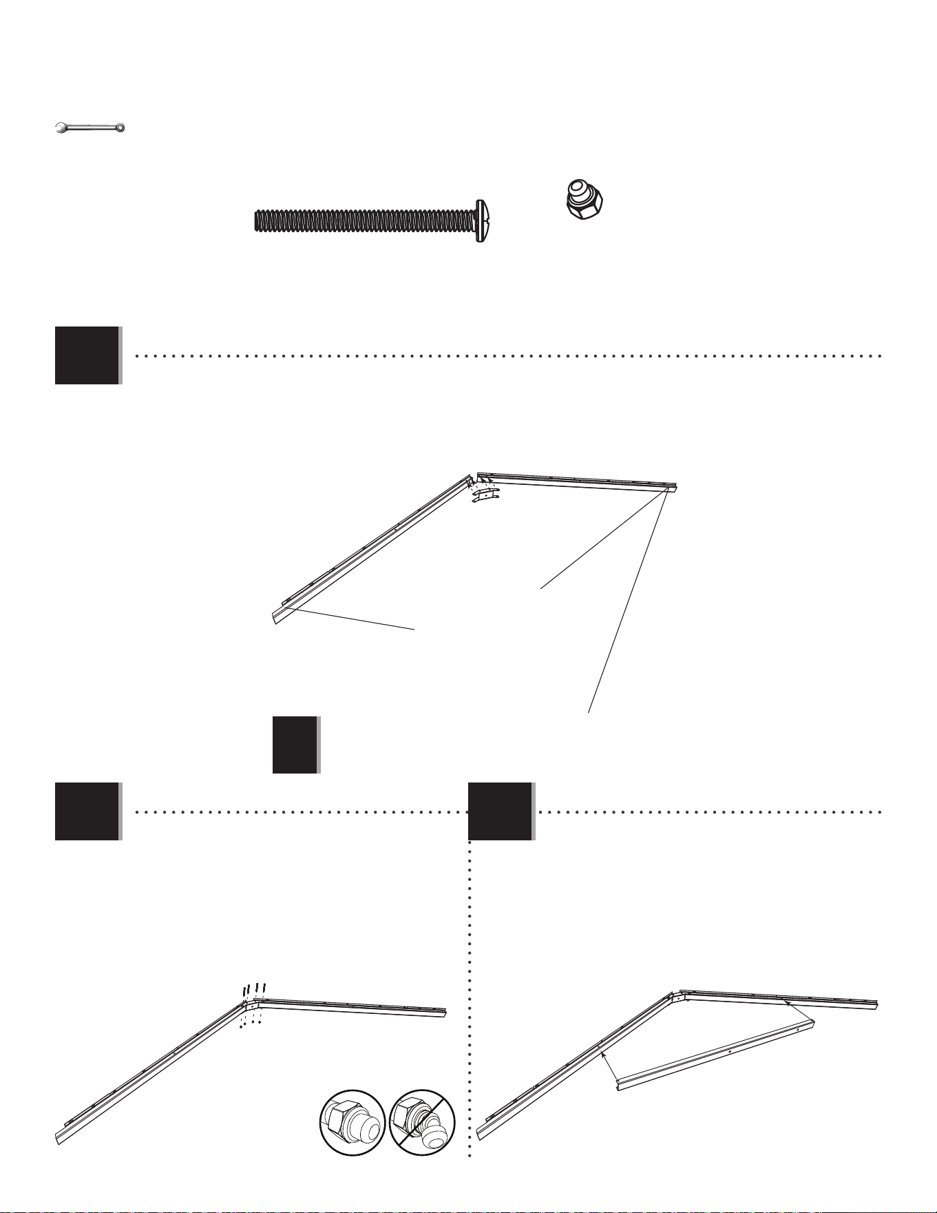
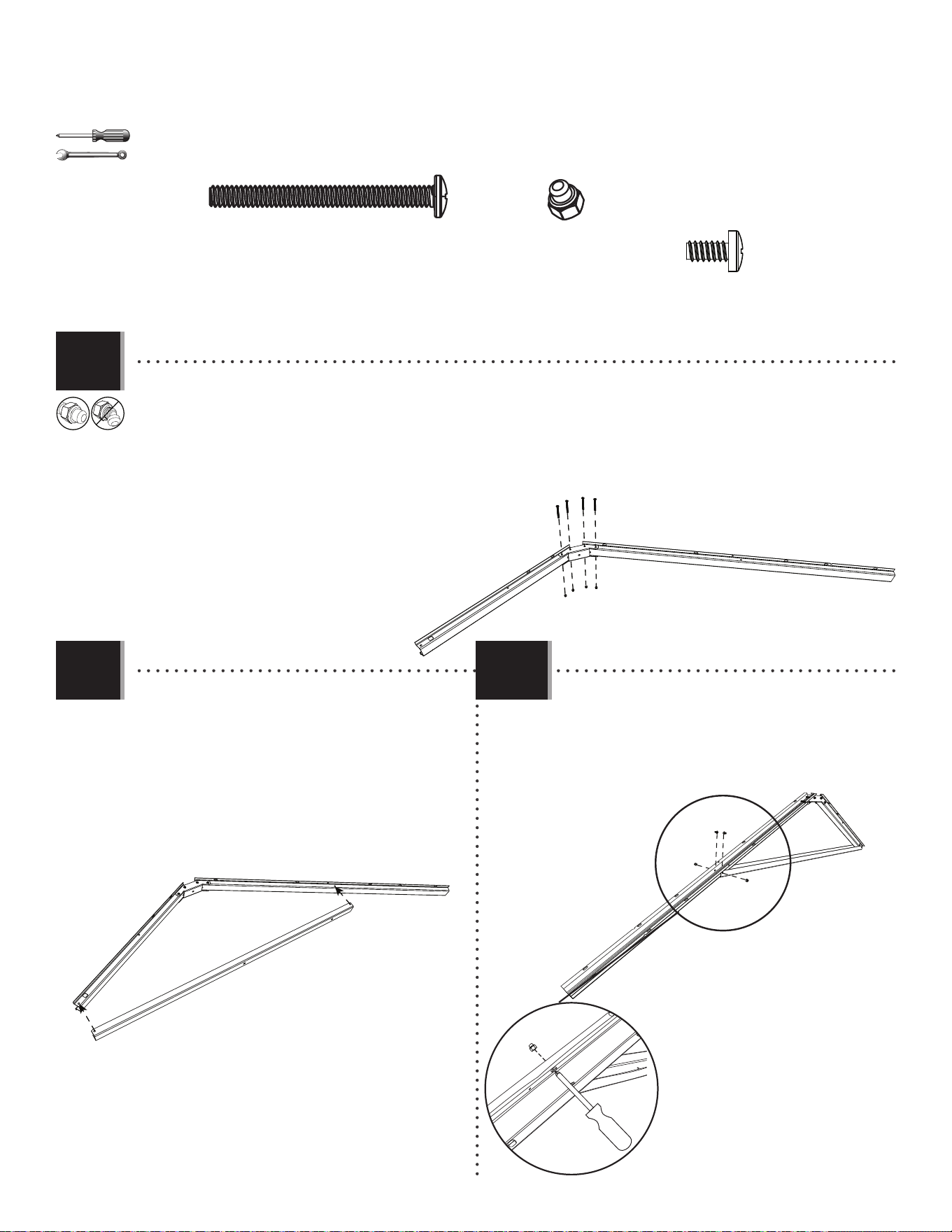
• Attach a Connector (AIP) to the end of two Truss Gutter Channels (DSQ & DSR) as shown.
• Attacher un raccord (AIP) à l’extrémité des canaux de gouttière (DSQ et DSR) comme indiqué.
• Sujetar un connector (AIP) a los extremos de los canalones de cercha (DSQ y DSR) como se muestra.
• Notch
• Encoche
• Muesca
• No Notch
• Sans encoche
• Sin muesca
• Attach a Connector (AIP) to the end of the Truss
Gutter Channels (DSQ & DSR) as shown.
• Attacher un raccord (AIP) à l’extrémité des canaux
de gouttière (DSQ et DSR) comme indiqué.
• Sujetar un connector (AIP) a los extremos de los
canalones de cercha (DSQ y DSR) como se muestra.
SIDE TRUSSES (x2) / FERMES LATÉRALES (x2) / CERCHAS LATERALES (x2)
• Note: Channel (DSR) has no notch at the end.
• Remarque : Le canal (DSR) n’a pas d’encoche à l’extrémité.
• Nota: El canalón (DSR) no tiene una muesca al extremo.
!
2.1
2.2 2.3
AFG
• Slide a Truss Brace (AFG) onto the Truss Gutter
Channels as shown.
• Faire glisser un support de ferme (AFG) sur les
cannaux de gouttière comme indiqué.
• Deslizar un soporte de cercha (AFG) sobre los
canalones de la cercha como se muestra.
13
TOOLS AND HARDWARE REQUIRED / OUTILS ET QUINCAILLERIE REQUIS / INSTRUMENTAL Y HERRAJE REQUERIDOS
X SECTION 2 (CONTINUED) / SECTION 2 (SUITE) / SECCIÓN 2 (CONTINUACIÓN)
ADY (x8)
ADY
ADK
ADK (x8)
ADY (x2)
ADY (x2)
ADK
ADK
ADK
ADK
3/8 in/po
(≈10 mm)
• Attatch the Truss Brace using the hardware provided. Do not
overtighten.
• Attacher le support de la ferme à l’aide de la quincaillerie
incluse. Ne pas serrer excessivement.
• Sujetar el soporte de la cercha usando el herraje indicado. No
apretar demasiado.
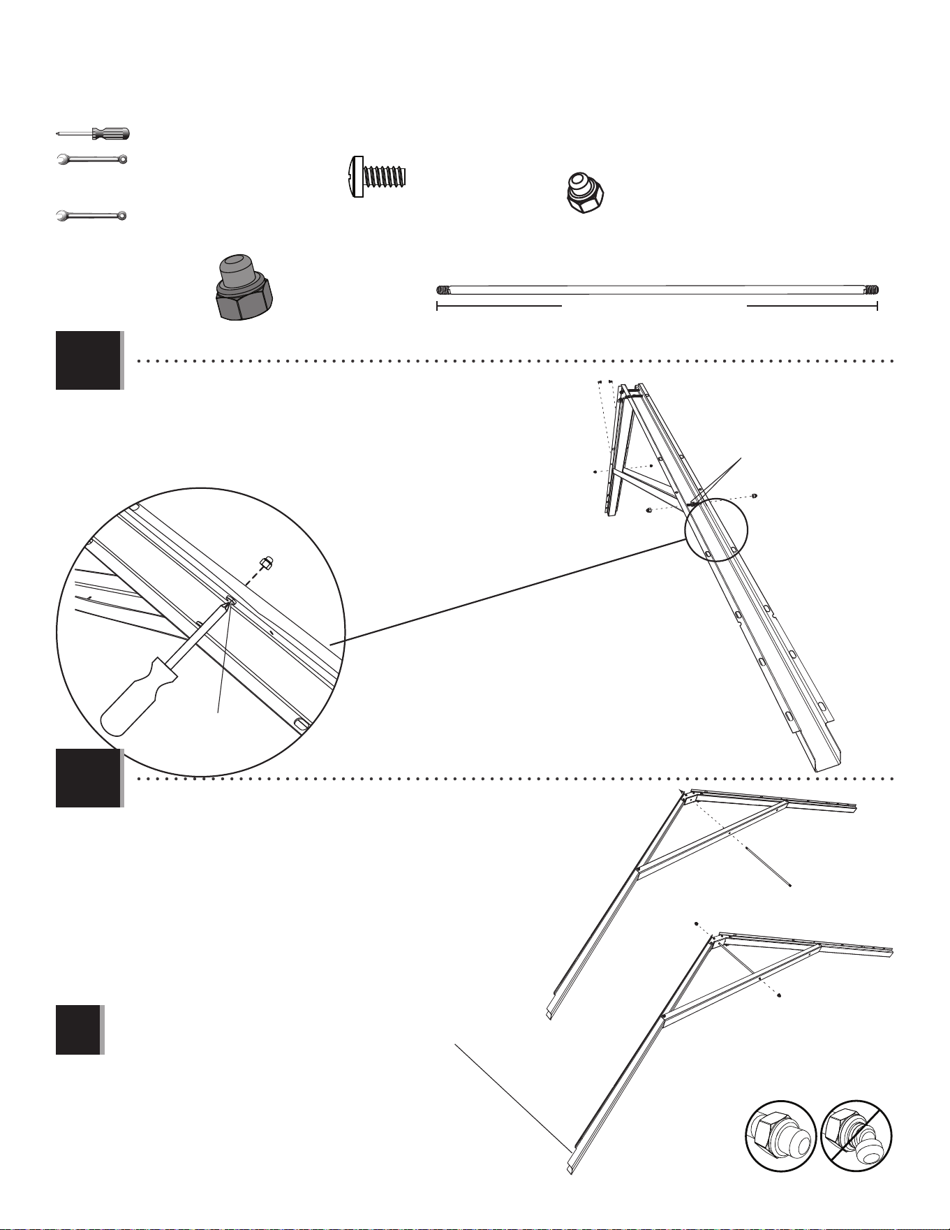
2.4
2.5
11 9/16 in/po (≈29,4 cm)
ADJ (x4)
ADH (x2)
7/16 in/po (x2)
(≈11 mm) (x2)
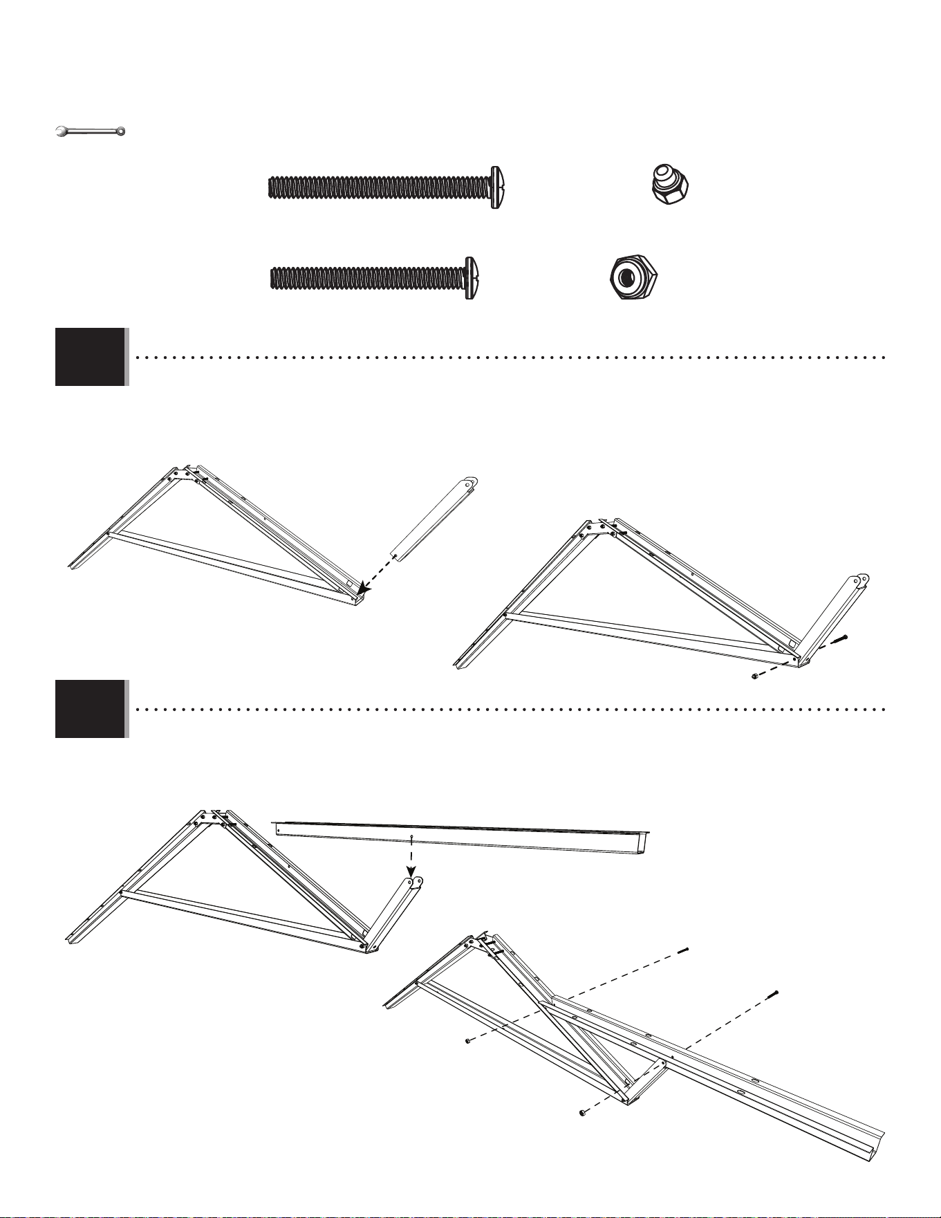
• Slide a Truss Rod (ADH) through the holes in the Brace and
Connector. Secure with two Cap Nuts (ADJ). Repeat the previous
steps for a second Side Truss.
• Faire glisser une tige (ADH) à travers les trous dans le
support et le raccord. Bien attacher-le à l’aide de deux
écrous borgnes (ADJ). Répéter les étapes précédentes pour une
deuxième ferme latérale.
• Deslizar una varilla (ADH) a través de los agujeros en el
Soporte y el conector. Sujetarla con dos tuercas ciegas (ADJ).
Repetir los pasos anteriores para una segunda cercha lateral.
ADJ
ADJ
ADH
• Note: This notched end will face the front of the shed.
• Remarque : Cette extrémité encochée fera face à la partie avant de l’abri.
• Nota: Este extremo muescado dará a la parte delantera de la caseta.
!
14
TOOLS AND HARDWARE REQUIRED / OUTILS ET QUINCAILLERIE REQUIS / INSTRUMENTAL Y HERRAJE REQUERIDOS
X SECTION 2 (CONTINUED) / SECTION 2 (SUITE) / SECCIÓN 2 (CONTINUACIÓN)
• Repeat the previous steps for one Truss Assembly without notches on both ends.
• Répéter les étapes précédentes pour ensembler une ferme sans les encoches aux deux extrémités.
• Repetir los pasos anteriores para ensamblar una cercha sin muescas a los dos extremos.
2.6
11 9/16 in/po (≈29,4 cm)
ADJ (x2)
ADH (x1)
7/16 in/po (x2)
(≈11 mm) (x2)
ADY (x4)
ADK (x8)
DTK (x4)
3/8 in/po (x2)
(≈10 mm) (x2)
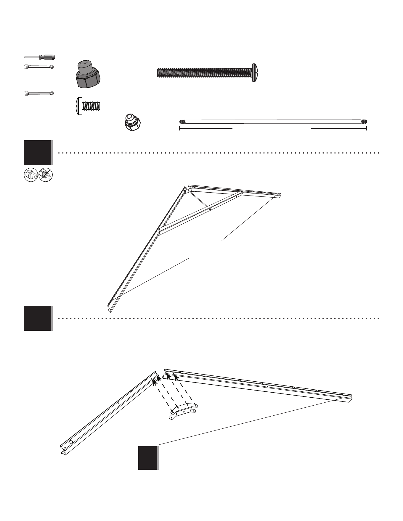
AIP
DSR
DSM
DSR
DSR
• Attach a Connector (AIP) to the end of two Truss Gutter Channels (DSM & DSR) as shown.
• Attacher un raccord (AIP) à l’extrémité des canaux de gouttière (DSM et DSR) comme indiqué.
• Sujetar un connector (AIP) a los extremos de los canalones de cercha (DSM y DSR) como se muestra.
CENTER TRUSS (x1) / FERME CENTRALE (x1) / ARMAZÓN CENTRAL (x1)
• Note: Channel (DSR) has no notch at the end.
• Remarque : Le canal (DSR) n’a pas d’encoche à l’extrémité.
• Nota: El canalón (DSR) no tiene una muesca al extremo.
!
2.7
Without notch
Sans encoche
Sin muesca
15
TOOLS AND HARDWARE REQUIRED / OUTILS ET QUINCAILLERIE REQUIS / INSTRUMENTAL Y HERRAJE REQUERIDOS
X SECTION 2 (CONTINUED) / SECTION 2 (SUITE) / SECCIÓN 2 (CONTINUACIÓN)
• Attach a Connector (AIP) to the end of two Truss
Gutter Channels using the hardware provided. Do
not overtighten the Cap Nuts (ADK).
• Attacher un raccord (AIP) à l’extrémité des canaux
de gouttière à l’aide de la quincaillerie incluse. Ne
pas trop serrer les écrous borgnes (ADK).
• Sujetar un connector (AIP) a los extremos
de los canalones de la cercha usando el
herraje indicado. No apretar demasiado las
tuercas ciegas (ADK).
DTK (x4)
ADK (x4)
ADK (x6)
DTK (x4)
DSR
DSM
3/8 in/po (x2)
(≈10 mm) (x2)
2.8
2.9
2.10
AFG
• Slide a Truss Brace (AFG) onto the Truss Gutter
Channels as shown.
• Faire glisser un support de ferme (AFG) sur les
canaux de gouttière comme indiqué.
• Deslizar un soporte de cercha (AFG) sobre los
canalones de la cercha como se muestra.
ADK
ADK
ADY (x2)
• Attatch the Truss Brace using the hardware
provided. Do not overtighten.
• Attacher le support de la ferme à l’aide de la
quincaillerie incluse. Ne pas serrer excessivement.
• Sujetar el soporte de la cercha usando el herraje
indicado. No apretar demasiado.
ADY (x2)
16
TOOLS AND HARDWARE REQUIRED / OUTILS ET QUINCAILLERIE REQUIS / INSTRUMENTAL Y HERRAJE REQUERIDOS
X SECTION 2 (CONTINUED) / SECTION 2 (SUITE) / SECCIÓN 2 (CONTINUACIÓN)
DSN
DTK
ADK
ADK (x1)
DTK (x2)
3/8 in/po (x2)
(≈10 mm) (x2)
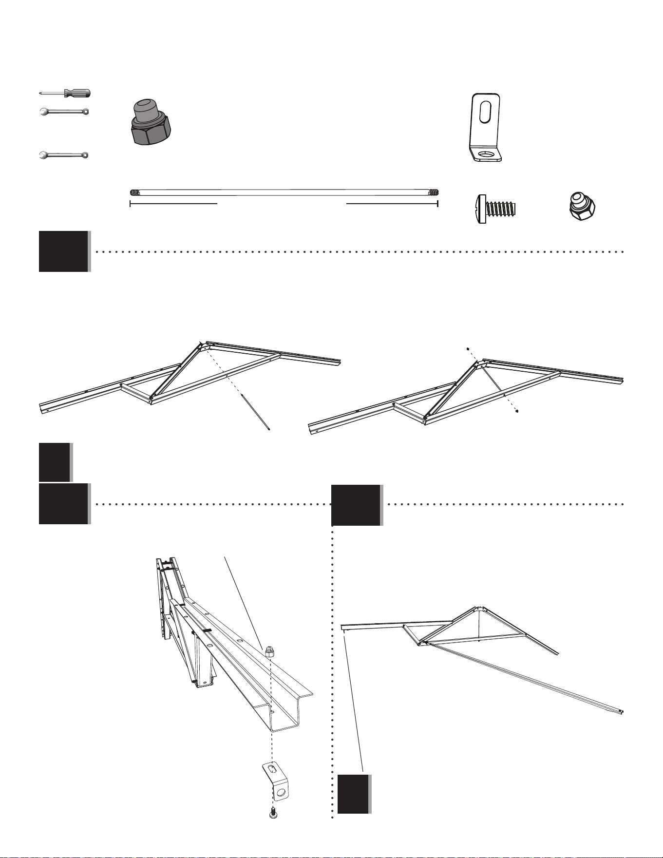
• Attach the Vertical Truss Brace (DSN) to the Truss. Only fi nger tighten this Nut (ADK) for now.
• Attacher le support vertical (DSN) à la ferme. Serrer l’écrou (ADK) à la main pour le moment.
• Fijar el soporte vertical (DSN) a la cercha. Apretar la tuerca (ADK) a mano por el momento.
• Secure the Horizontal Truss Brace (DSO) to the Truss with the hardware shown. Now, tighten the Nut from Step 2.11.
• Attacher le support horizontal (DSO) à la ferme à l’aide de la quincaillerie incluse. Maintenant, serrer l’écrou de l’étape 2.11.
• Sujetar el soporte horizontal (DSO) a la cercha usando el herraje indicado. Ahora, apretar la tuerca del paso 2.11.
CXK (x2)
DTJ (x1)
DSO
DTJ
DTK
CXK
CXK
2.11
2.12
17
TOOLS AND HARDWARE REQUIRED / OUTILS ET QUINCAILLERIE REQUIS / INSTRUMENTAL Y HERRAJE REQUERIDOS
X SECTION 2 (CONTINUED) / SECTION 2 (SUITE) / SECCIÓN 2 (CONTINUACIÓN)
ADH
ADH (x1)
11 9/16 in/po (≈29,4 cm)
ADJ
ADJ
ADJ (x2)
7/16 in/po (x2)
(≈11 mm) (x2)
• Slide a Truss Rod (ADH) through the holes in the Brace and Connector. Secure with two Cap Nuts (ADJ).
• Faire glisser une tige (ADH) à travers les trous dans le support et le raccord. Bien attacher-le à l’aide de deux écrous borgnes (ADJ).
• Deslice una varilla (ADH) a través de los agujeros en el soporte y el conector. Sujetarla con dos tuercas ciegas (ADJ).
• Note: Do not overtighten the Cap Nuts (ADJ).
• Remarque : Ne pas trop serrer les écrous borgnes (ADJ).
• Nota: No apretar demasiado las tuercas ciegas (ADJ).
!
2.13
• Only tighten the Nut (ADK) by hand in this step.
• Ne serrer l’écrou (ADK) qu’à la main dans cette étape.
• Sólo apretar la tuerca (ADK) à mano en este paso.
ADY
ADK
AHT
2.14
2.15
ADY (x1)
ADK (x1)
AHT (x1)
3/8 in/po (x2)
(≈10 mm) (x2)
DSP
• Slide the Support Tube (DSP) through the hole in the
Front Truss Channel and center it.
• Faire glisser le tube de support (DSP) à travers le
trou dans le canal de gouttière avant et centrer-le.
• Deslizar le tubo de soporte (DSP) a través del agujero
en el canalón de la cercha delantero y centrarlo.
• Note: This end will face the front of the shed.
• Remarque : Cette extrémité fera face à la partie avant de l’abri.
• Nota: Este extremo dará a la parte delantera de la caseta.
!
18
GABLE ASSEMBLY / ASSEMBLAGE DES PIGNONS / ENSAMBLE DE LAS FACHADAS
3
46 in/po (≈1,17 m)
BDD (x1)
AGI (x2)
AGH (x2)
BDC (x1)
ADV (x4)
AHS (x2)
ADW (x10)
AEE (x10)
AGP (x2) AIQ (x2)
ADZ (x8)
FDN
Metal Parts / Pièces en métal / Piezas de metal
Plastic Parts / Pièces en plastique / Piezas de plástico
Hardware Bag / Sac de quincaillerie / Bolsa de herraje
TOOLS REQUIRED / OUTILS REQUIS / INSTRUMENTAL REQUERIDO
PARTS REQUIRED / PIÈCES REQUISES / PIEZAS REQUERIDAS
HARDWARE REQUIRED / QUINCAILLERIE REQUISE / HERRAJE REQUERIDO
19
TOOLS AND HARDWARE REQUIRED / OUTILS ET QUINCAILLERIE REQUIS / INSTRUMENTAL Y HERRAJE REQUERIDOS
X SECTION 3 (CONTINUED) / SECTION 3 (SUITE) / SECCIÓN 3 (CONTINUACIÓN)
ADZ (x8)
AGH
AGI
ADZ
ADZ
AIQ
AGP
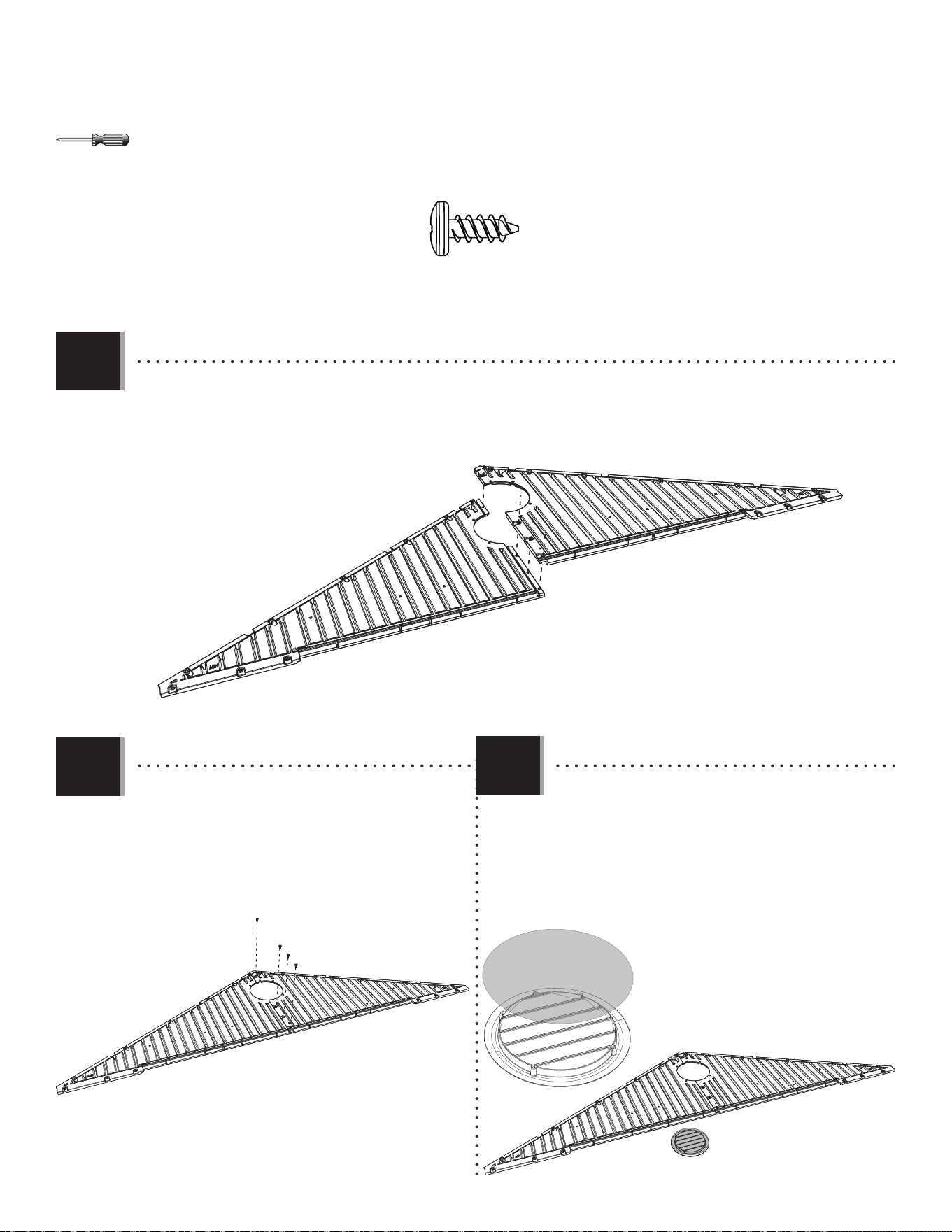
• Align the holes in the Left (AGH) and Right (AGI) Rear Gable Halves.
• Aligner les trous dans les pignons gauche (AGH) et droite (AGI).
• Alinear los agujeros en las fachadas traseras izquierda (AGH) y derecha (AGI).
• Place the Screen (AIQ) over the Vent (AGP) and align
the fi ve holes in the Vent with those in the Gable.
• Mettre la moustiquaire (AIQ) sur l’évent (AGP), et
aligner les cinq trous dans l’évent avec ceux du
pignon.
• Colocar el mosquitero (AIQ) sobre la rejilla de
ventilación (AGP), y alinear los agujeros en la Rejilla
con los de la fachada.
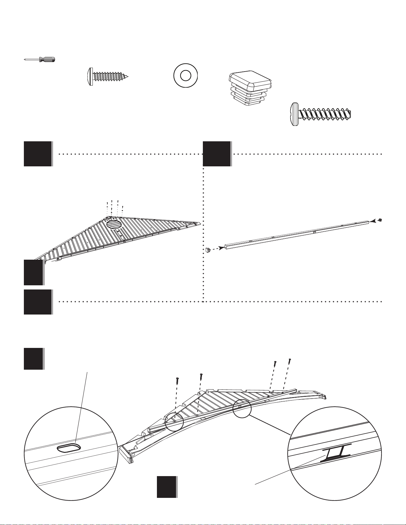
• Secure the two Gable Halves with four (4) Screws
(ADZ).
• Attacher l’un à l’autre à l’aide de quatre (4) vis
(ADZ).
• Sujetar el uno al otro usando cuatro (4) tornillos
(ADZ).
3.1
3.2
3.3
20
TOOLS AND HARDWARE REQUIRED / OUTILS ET QUINCAILLERIE REQUIS / INSTRUMENTAL Y HERRAJE REQUERIDOS
X SECTION 3 (CONTINUED) / SECTION 3 (SUITE) / SECCIÓN 3 (CONTINUACIÓN)
ADW
AEE
ADV (x4)
AHS (x2)
AHS
AHS
BDC
BDD
• Align the holes in the Header with those in the Entry Gable (BDC). Secure with the hardware provided.
• Aligner les trous dans le linteau avec ceux du pignon d’entrée (BDC). Attacher les uns aux autres de la quincaillerie
incluse.
• Alinear los agujeros en el dintel con ellos en la fachada de entrada (BDC). Sujetar los unos a los otros usando el
herraje incluido.
ADV
ADV
• Secure with the hardware provided.
• Attacher les uns aux autres de la quincaillerie
incluse.
• Sujetar los unos a los otros usando el herraje
incluido.
ADW (x10)
AEE (x10)
• Insert an End Cap (AHS) into each end of the Header
(BDD).
• Insérer un capuchon dans chaque extrémité du
linteau (BDD).
• Insertar un tapón (AHS) en los dos extremos del
dintel (BDD).
• Repeat the previous steps for the second Vent.
• Répéter les étapes précédentes pour la deuxième évent.
• Repetir los pasos anteriores para la segunda rejilla.
• The fl at holes face away from the Gable.
• Les trous plats doivent être face à l’écart du pignon.
• Los agujeros planos dan hacia afuera.
• The dented hole faces downward.
• Orienter le trou fendu vers le bas.
• Orientar el agujero abollado hacia abajo.
!
!
!
3.4
3.5
3.6
21
LEFT DOOR ASSEMBLY / ASSEMBLAGE DE LA PORTE GAUCHE / ENSAMBLE DE LA PUERTA IZQUIERDA
4
BDJ (x1)
EDW (x1)
74 5/8 in/po (≈1,90 m)
Metal Parts / Pièces en métal / Piezas de metal
Hardware Bags / Sacs de quincaillerie / Bolsas de herraje
Plastic Parts / Pièces en plastique / Piezas de plástico
Top End / Extrémité supérieure / Extremo superior
TOOLS REQUIRED / OUTILS REQUIS / INSTRUMENTAL REQUERIDO
PARTS REQUIRED / PIÈCES REQUISES / PIEZAS REQUERIDAS
HARDWARE REQUIRED / QUINCAILLERIE REQUISE / HERRAJE REQUERIDO
ADC (x1)
CRE (x1)
74 1/2 in/po (≈1,89 m)
BYR (x1)
BYS (x1)
ADW (x1)
BBH (x1)
BYZ (x2)
AEE (x3)
FFY
DHL
ARA (x1) 1/8 in/po (3 mm)
AEB (x2)
ENO (x4)
ACH (x2)
AAB (x2)
EEP (x1)
DGR (x1)
DGS (x1)
ENP (x2)
Upper / Supérieur / Superior
Lower / Inférieur / Inferior
ADZ (x14)
EPH (x1)
DHN (x1)
22
TOOLS AND HARDWARE REQUIRED / OUTILS ET QUINCAILLERIE REQUIS / INSTRUMENTAL Y HERRAJE REQUERIDOS
X SECTION 4 (CONTINUED) / SECTION 4 (SUITE) / SECCIÓN 4 (CONTINUACIÓN)
BBH (x1)
EDW
BDJ
• Align these holes in the next step
• Aligner ces trous à l’étape suivante
• Alinear estos agujeros en el paso siguiente
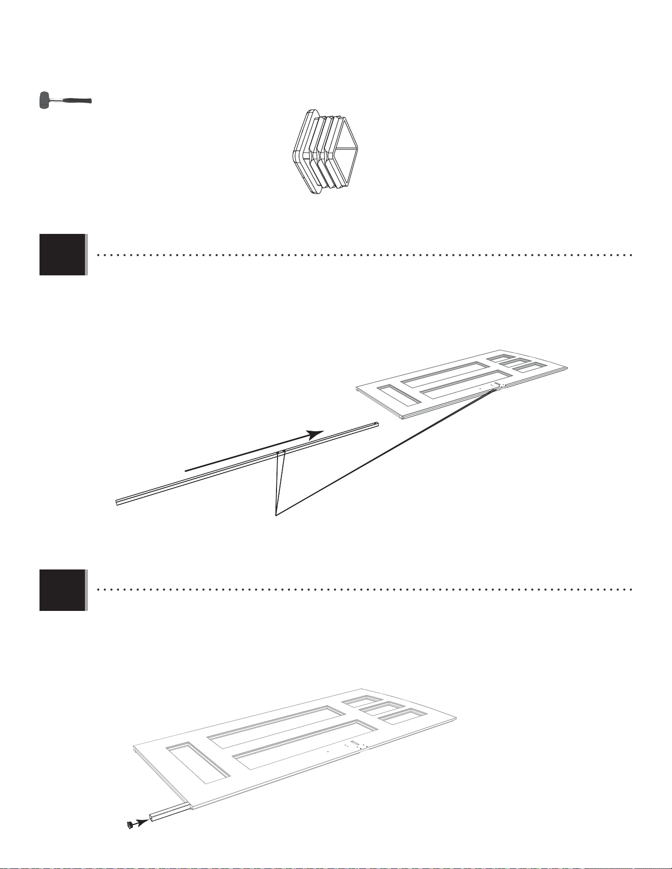
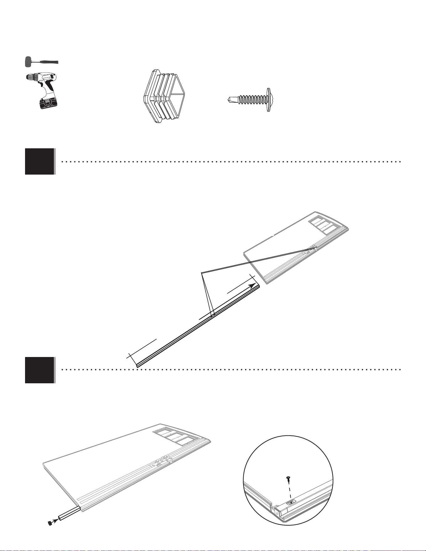
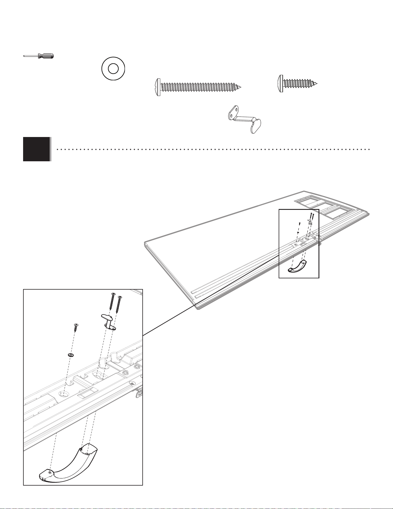
• Insert an End Cap (BBH) into the end of the Tube, and fi nish inserting the Tube until fl ush with bottom of Door and
the two holes in the Tube align with those in the Door.
• Insérer un capuchon (BBH) dans l’extrémité du tube, et continuer d’insérer le tube jusqu’à ce qu’il soit à ras au bord
inférieur de la porte et les deux trous dans le tube s’alignent avec ceux dans la porte.
• Insertar un tapon (BBH) adentro del extremo del tubo, y seguir con la inserción del tubo hasta que esté al ras del
borde inferior de la puerta y los dos agujeros en el tubo se alineen con ellos en la puerta.
BBH
4.2
4.1
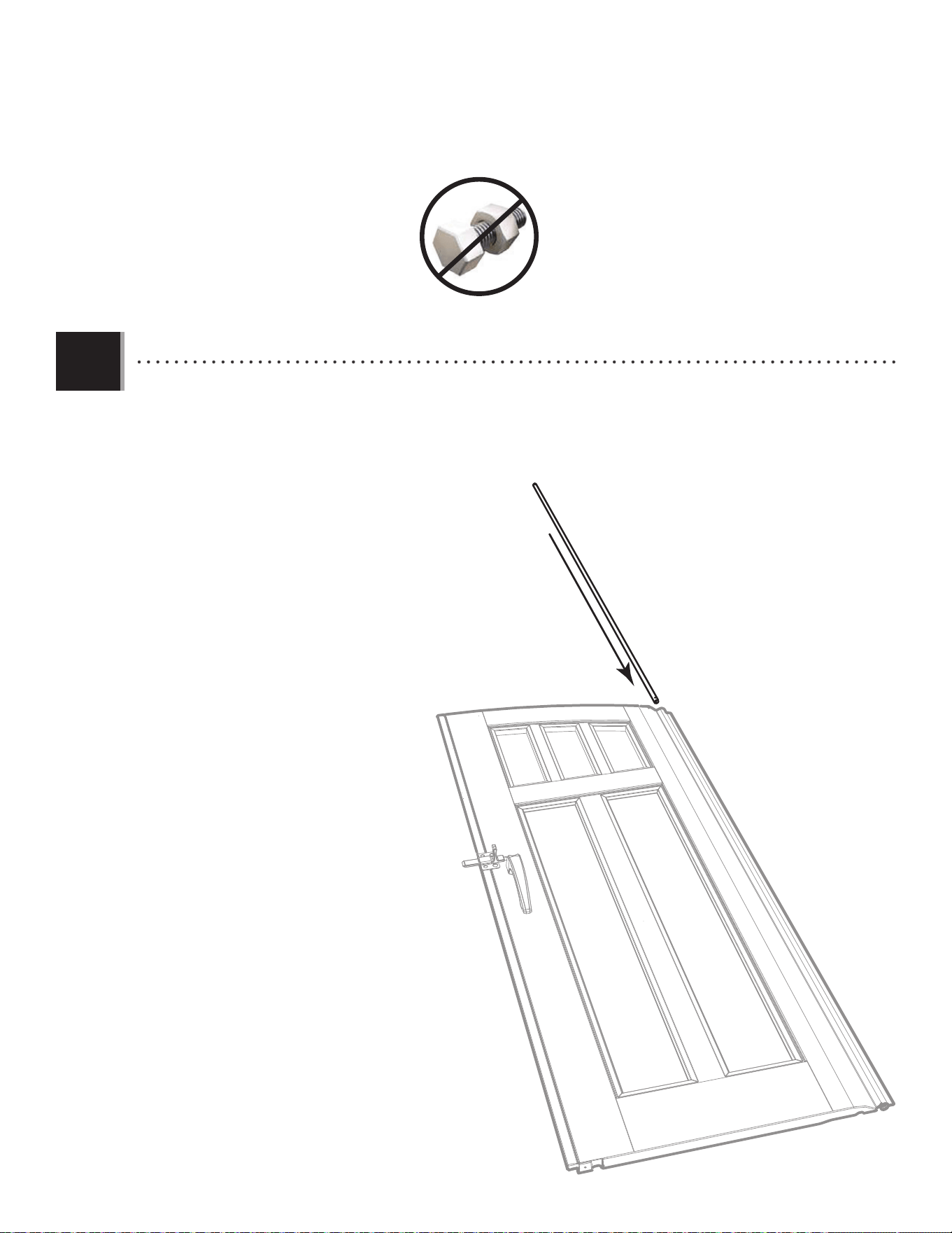
• Slide a Long Tube (EDW) into the hole in the Left Door (BAJ) until a few inches remain out of the Door. The end with the
hole goes at the top.
• Faire glisser le tube grand (EDW) à travers le trou de la porte gauche (BDJ) jusqu’à ce qu’il dépasse quelques pouces
de la porte. L’extrémité avec le trou va vers le haut.
• Deslizar el tubo largo (EDW) adentro del agujero en la puerta izquierda (BDJ) hasta que el tubo cuelgue unas pulgadas
de la puerta. El extremo con el agujero va al tope.
23
TOOLS AND HARDWARE REQUIRED / OUTILS ET QUINCAILLERIE REQUIS / INSTRUMENTAL Y HERRAJE REQUERIDOS
X SECTION 4 (CONTINUED) / SECTION 4 (SUITE) / SECCIÓN 4 (CONTINUACIÓN)
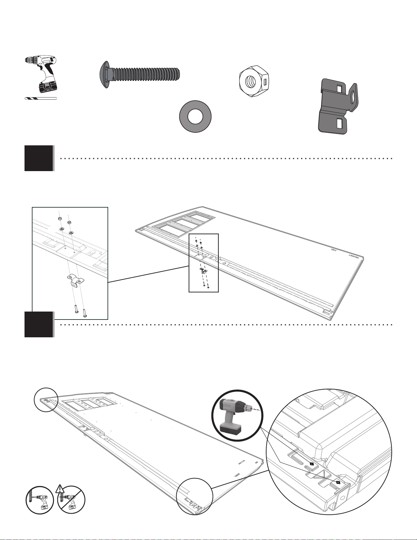
4.3
4.4
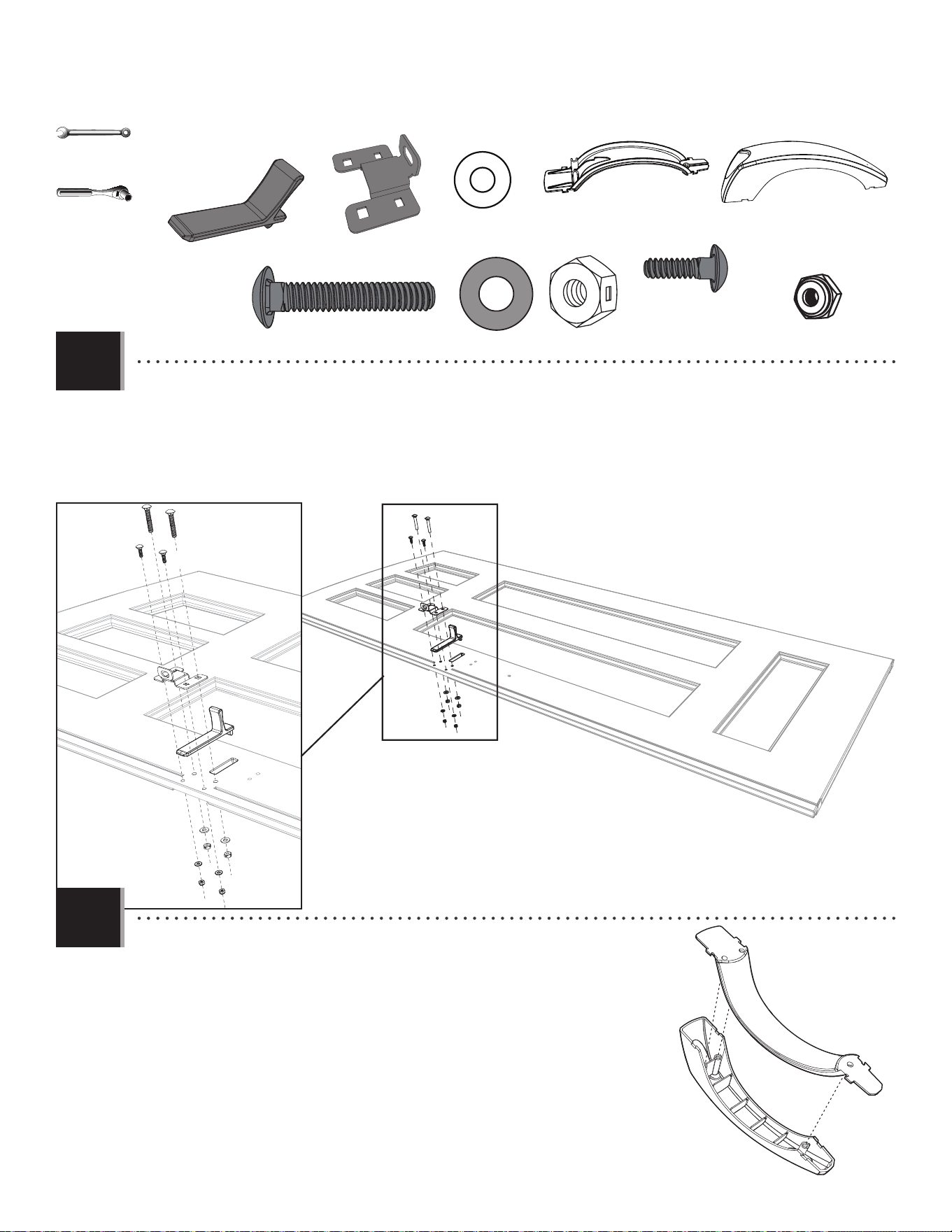
• Attach the Left Latch Bracket (EEP) to the Door using the hardware included. Tighten only by hand at this point.
• Attacher le support gauche à loquet (EEP) à la porte à l’aide de la quincaillerie incluse. Serrer-les à la main seulement en
ce moment.
• Sujetar el soporte izquierdo para el pestaño (EEP) a la puerta usando el herraje incluido. Apretarlos sólo a mano en este
momento.
AAB (x2)
AAB
AAB
ACH (x2)
ACH
ACH
AEB (x2)
AEB
AEB
EEP (x1)
EEP
• Drill into the divots at the top and bottom of the Door and into the Tube inside but not all the way through the
Door. Use the 1/8" (3 mm) Drill Bit (ARA) included.
• Percer les marques à la partie supérieure et inférieure de la porte et dedans le tube à l’intéreiur mais pas à travers
la porte entière. Utiliser le Foret de 3 mm (1/8 po) (ARA) inclus.
• Taladrar las marcas al tope y al fondo de la puerta y dentro del tubo adentro mas no por la puerta entera. Usar la
broca de 3 mm (1/8 in.) (ARA) incluida.
!
1/8 in/po
(3 mm)
ARA (x1)
24
TOOLS AND HARDWARE REQUIRED / OUTILS ET QUINCAILLERIE REQUIS / INSTRUMENTAL Y HERRAJE REQUERIDOS
X SECTION 4 (CONTINUED) / SECTION 4 (SUITE) / SECCIÓN 4 (CONTINUACIÓN)
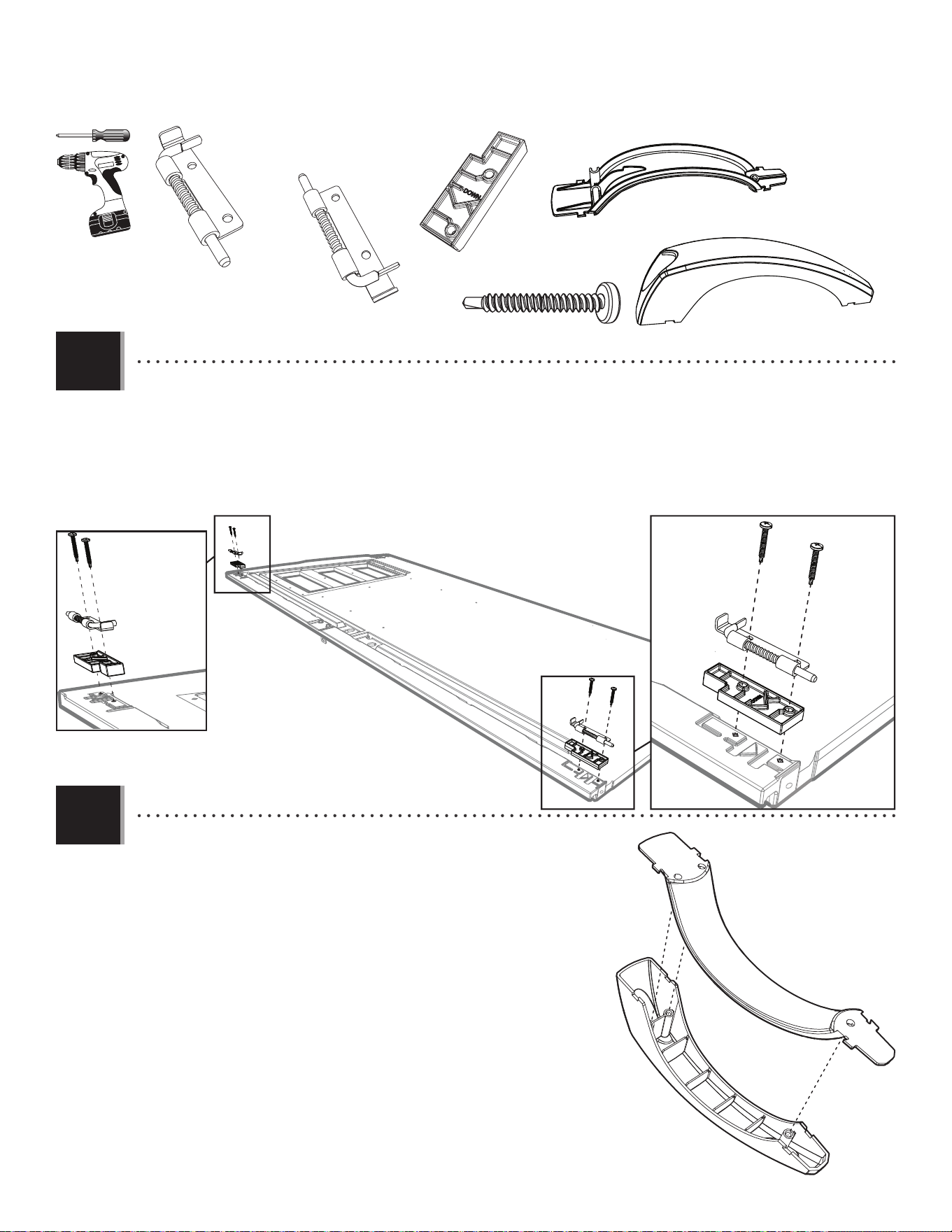
4.5
4.6
BYS
BYR
• Attach the two Handle Pieces (BYR & BYS) together as shown.
• Attacher les deux pièces de la poignée (BYR et BYS) comme illustré.
• Conectar las dos piezas del picaporte (BYR y BYS) como se muestra.
• Attach the Locks (DGS & DGR) and Spacers (ENP) to the top and bottom of the Left Door. If the pins in the Locks do not
move freely, loosen the Screws (ENO) just a tad.
• Attacher les verrous (DGS et DGR) et les pièces d’écartement (ENP) à la partie supérieure et inférieure à la porte gauche.
Si les verrous ne se déplacent pas librement, deserrer les vis (ENO) un pétit peu.
• Sujetar los pasadores (DGS y DGR) y los espaciadores (ENP) al tope y al fondo de la puerta izquierda. Si los pasadores no
se mueven libremente, afl ojar los tornillos (ENP) un poquito.
DGR (x1)
DGR
ENO
ENO
ENO
DGS
DGS (x1)
ENP (x2)
ENO (x4)
ENP
ENP
Upper / Supérieur / Superior
Lower / Inférieur / Inferior
BYS (x1)
BYR (x1)
25
TOOLS AND HARDWARE REQUIRED / OUTILS ET QUINCAILLERIE REQUIS / INSTRUMENTAL Y HERRAJE REQUERIDOS
X SECTION 4 (CONTINUED) / SECTION 4 (SUITE) / SECCIÓN 4 (CONTINUACIÓN)
CRE
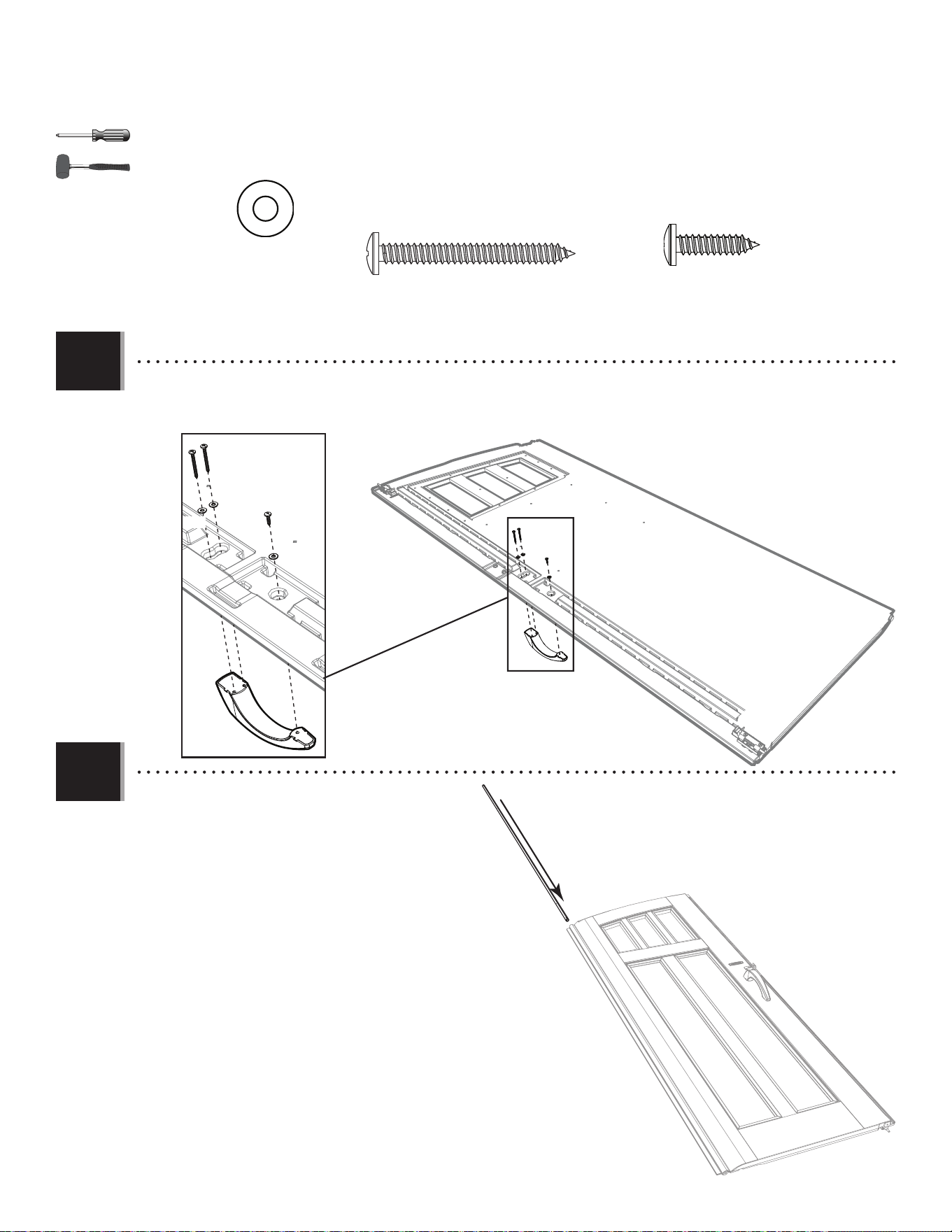
4.7
4.8
• Slide a Hinge Tube (CRE) into the hole in the Door
until a few inches remain out of the bottom.
• Faire glisser le tube de charnière (CRE) à travers le
trou de la porte jusqu’à ce qu’il dépasse quelques
pouces de la partie inférieure de la porte.
• Deslizar un tubo de bisagra (CRE) adentro del
agujero en la puerta hasta que el tubo cuelgue unas
pulgadas de la parte inferior de la puerta.
• Attach the Handle to the Door using the hardware included.
• Attacher la poignée à la porte à l’aide de la quincaillerie incluse.
• Sujetar el picoporte a la puerta usando el herraje incluido.
ADW (x1)
ADW
BYZ (x2)
BYZ (x2)
AEE (x3)
AEE
AEE
AEE
26
TOOLS AND HARDWARE REQUIRED / OUTILS ET QUINCAILLERIE REQUIS / INSTRUMENTAL Y HERRAJE REQUERIDOS
X SECTION 4 (CONTINUED) / SECTION 4 (SUITE) / SECCIÓN 4 (CONTINUACIÓN)
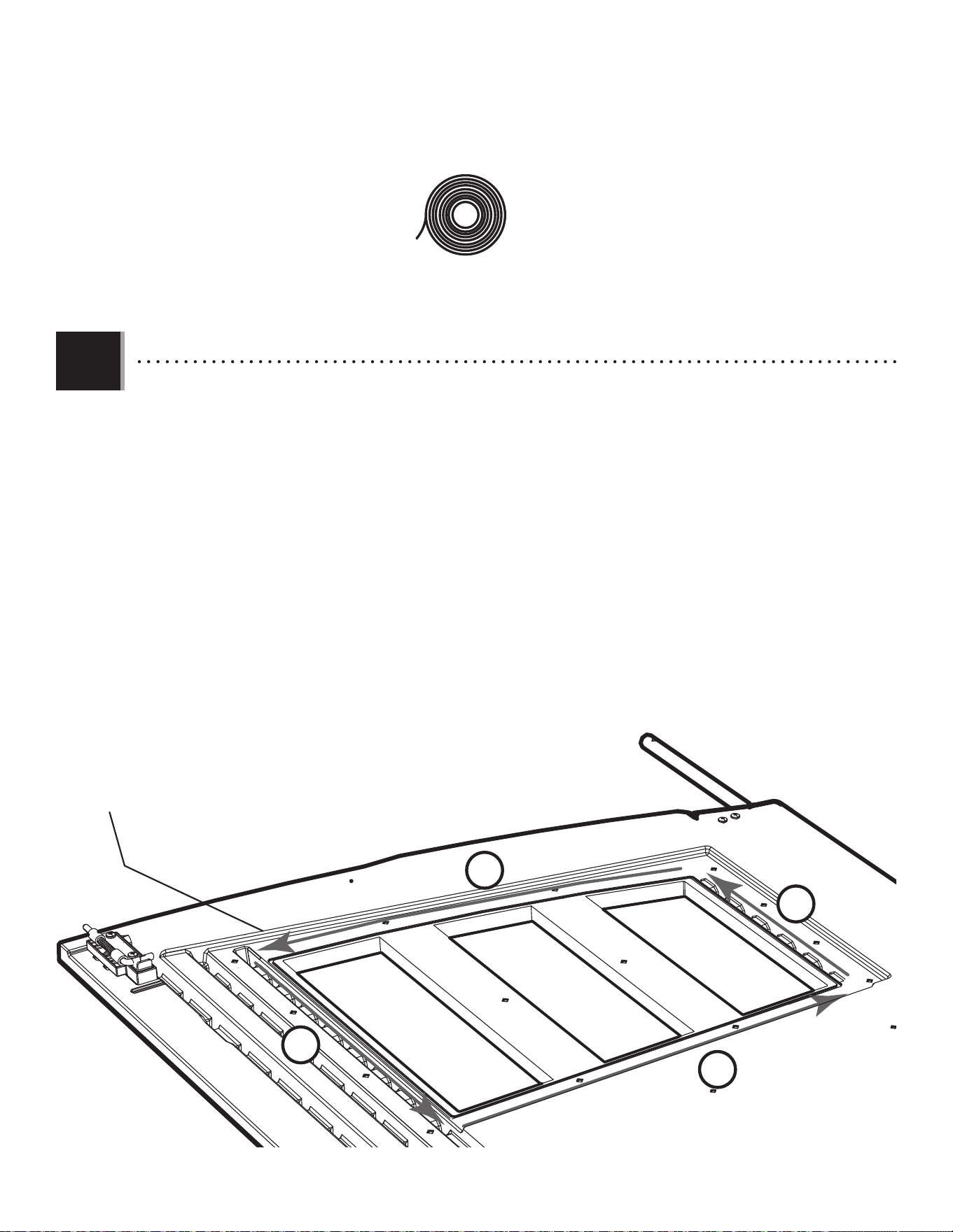
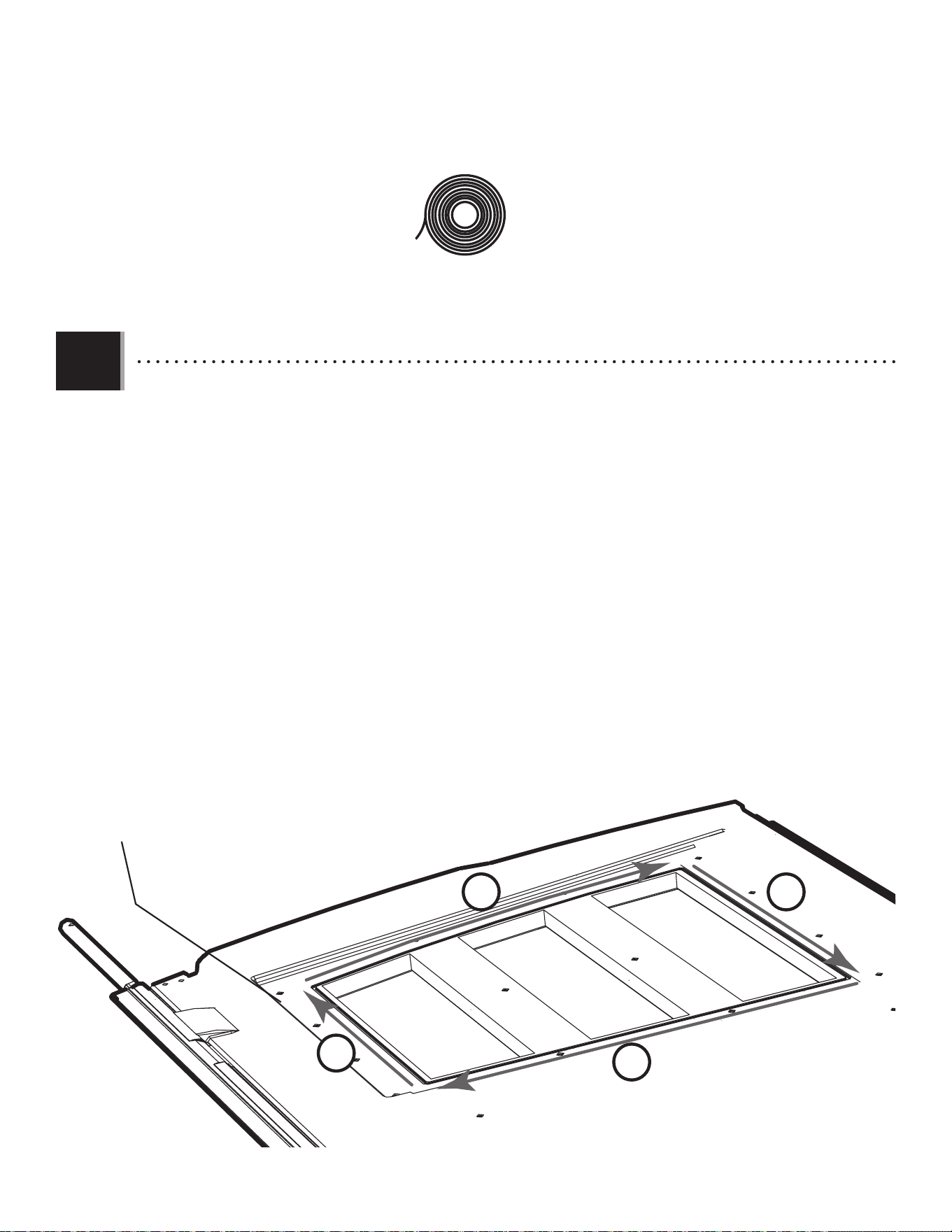
• There is a narrow groove (illustrated in black) running along the outside of the window on the back of each Door.
Starting at the top, left corner of the groove in the Left Door, lay the 1/8" (3 mm) bead of Butyl Tape (EPH) into the
groove. Do not worry about getting the bead completely into the groove just yet—simply lay the bead over the groove. Do not press
the bead into the groove. Do not stretch the bead. Work your way downward (1) and, as you get to each corner, peel off the
paper backing from the tape you just laid (peel off backing at each corner). Go along the bottom (2) of the window.
Curve your way upward (3) and then along the top (4) of the window until you’re back where you started. Clip off the
excess.
• Une rainure étroite (illustrée en noir) se trouve le long de l’extérieur de la fenêtre à l’arrière de chaque porte.
Partant du coin supérieur gauche de la rainure de la porte gauche, étendre une goutte de 1/8 po (3 mm) de ruban
butylique (EPH) dans la rainure. Ne pas s’inquiéter si la goutte n’est pas complètement dans la rainure en ce moment, ne faire que
déposer la goutte sur la rainure. Ne pas pousser la goutte dans la rainure. Ne pas étirer le goutte. Travailler vers le bas (1) et, en
approchant chaque courbe, retirer le papier protecteur du ruban récemment étendé (retirer le papier protecteur a
chaque courbe). Étendre le ruban le long du bas (2) de la fenêtre. Courber vers le haut (3), puis le long du haut (4) de
la fenêtre jusqu’à revenir au point de départ. Couper l’excédent.
• Hay una ranura angosta (ilustrada en negro) bordeando la ventana en la superfi cie posterior de cada puerta.
Comenzando desde arriba, en la esquina izquierda de la ranura en la puerta izquierda, aplicar una línea de 3 mm
(1/8 in) de cinta butílica (EPH) en de la ranura. Ne preocuparse por poner la cinta, mas solamente poner la cinta sobre la ranura.
No presionar la cinta dentro de la ranura. No estirar la línea. Seguir hacia abajo (1) y, al acercar cada ángulo, quitar el papel
protector de la cinta recién aplicada (quitar el papel protector a cada ángulo). Seguir a lo largo del borde inferior (2)
de la ventana. Curvearla hacia arriba (3) y, entonces, a lo largo del borde superior (4) de la ventana hasta estar al
punto de partida. Cortar el exceso.
Groove / Rainure / Ranura
EPH (x1)
1
2
3
4
4.9
27
TOOLS AND HARDWARE REQUIRED / OUTILS ET QUINCAILLERIE REQUIS / INSTRUMENTAL Y HERRAJE REQUERIDOS
X SECTION 4 (CONTINUED) / SECTION 4 (SUITE) / SECCIÓN 4 (CONTINUACIÓN)
ADZ (x14)
DHN
ADZ
ADZ
ADZ
ADZ
ADZ
ADZ
ADZ
ADZ
ADZ
ADZ
ADZ
ADZ
ADZ
ADZ
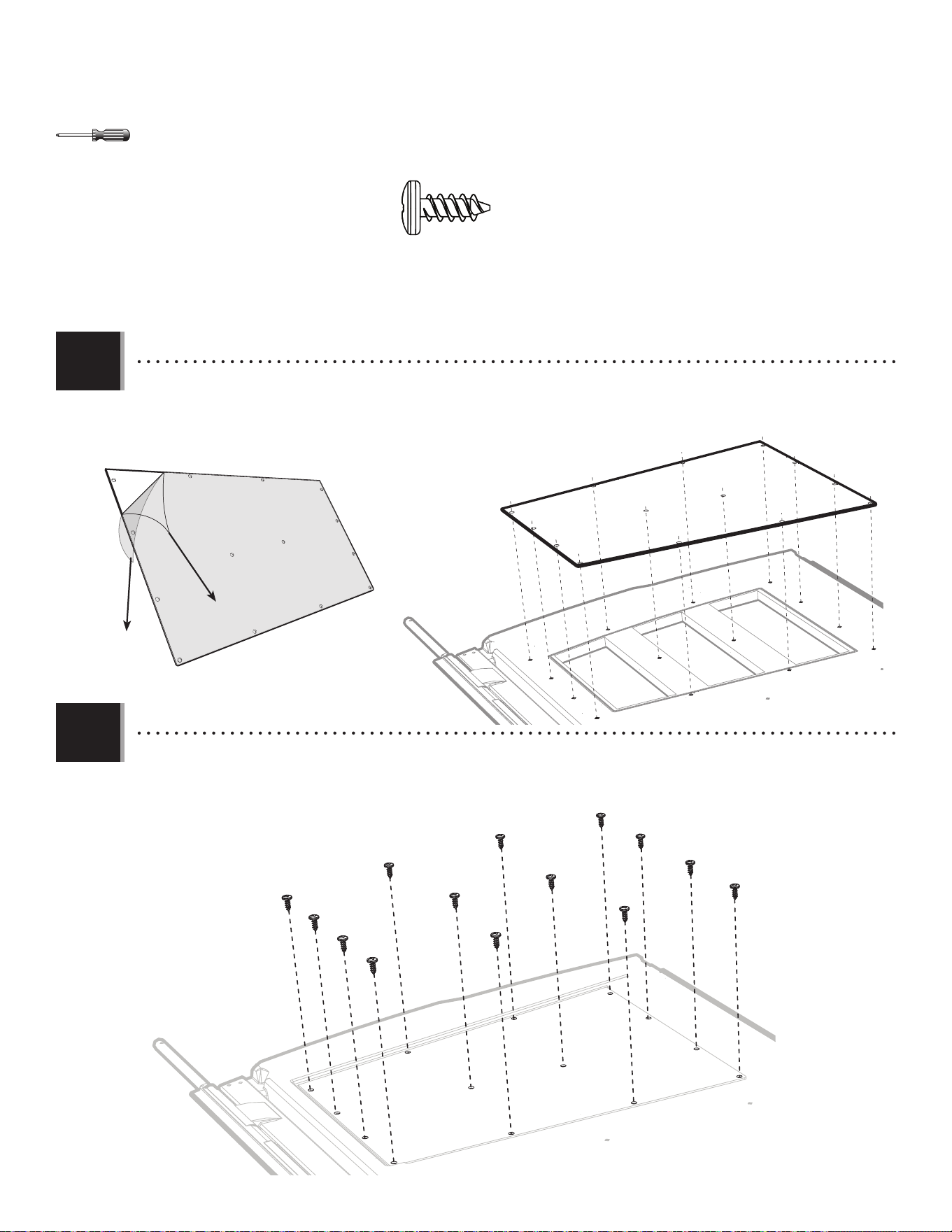
• Align the holes in the Pane with those in the Door, and gently set a Window Pane (DHN) down onto the Door.
• Aligner les trous dans le carreau avec ceux de la porte, et mettre le carreau (DHN) sur la porte.
• Alinear los agujeros en la hoja con los de la puerta, y colocar ligeramente la hoja de ventana (DHN) en la puerta.
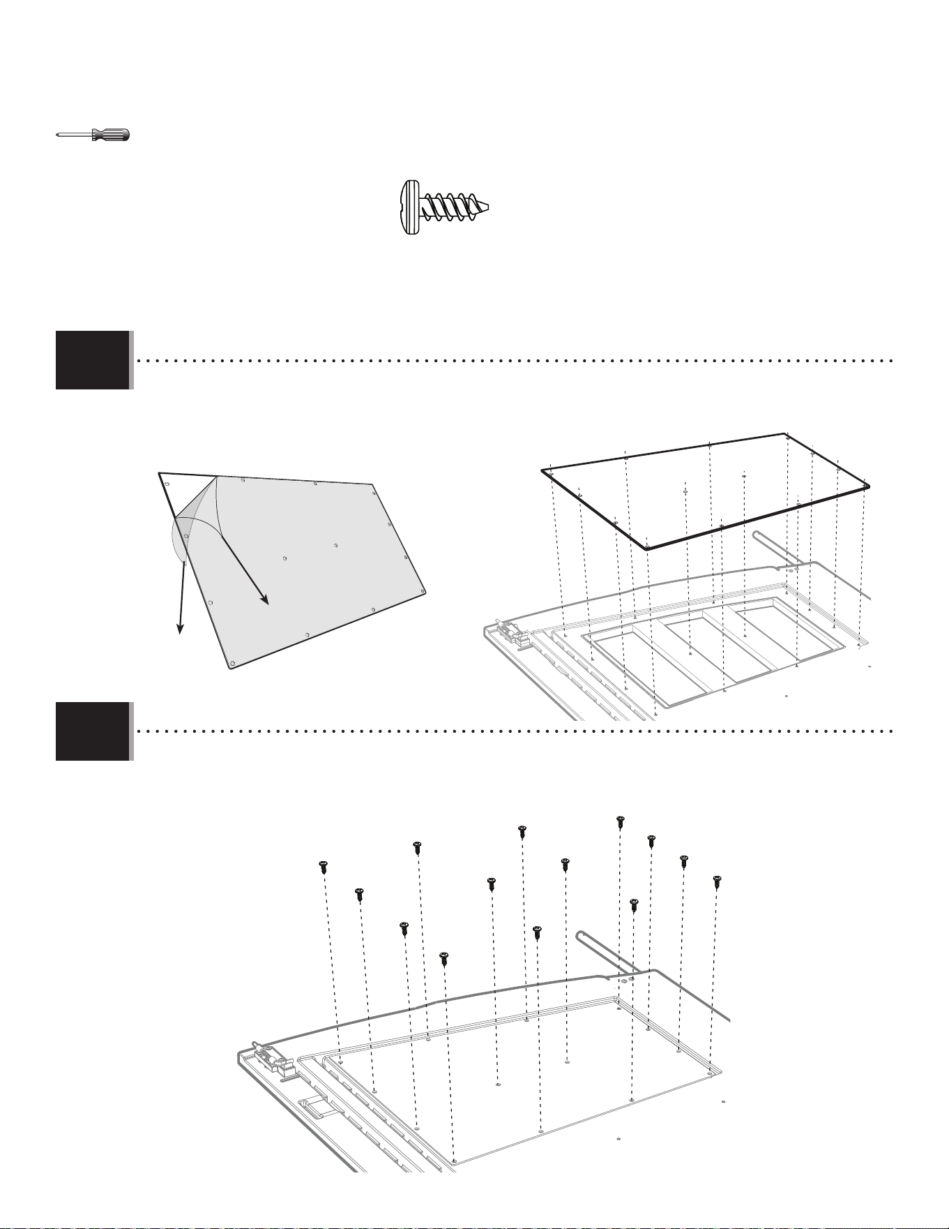
• Secure the Pane to the Door using fourteen (14) Screws (ADZ).
• Fixer le carreau à la porte en utilisant quatorze (14) vis (ADZ).
• Sujetar la hoja a la puerta usando catorce (14) tornillos (ADZ).
4.10
4.11
DHN
28
RIGHT DOOR ASSEMBLY / ASSEMBLAGE DE LA PORTE DROITE / ENSAMBLE DE LA PUERTA DERECHA
5
EDG
Hardware Bags / Sacs de quincaillerie / Bolsas de herraje
HARDWARE REQUIRED / QUINCAILLERIE REQUISE / HERRAJE REQUERIDO
Metal Parts / Pièces en métal / Piezas de metal
PARTS REQUIRED / PIÈCES REQUISES / PIEZAS REQUERIDAS
TOOLS REQUIRED / OUTILS REQUIS / INSTRUMENTAL REQUERIDO
ARA (x1) 1/8 in/po (3mm) 7/16 in/po (11 mm) 3/8 in/po (10 mm)
BDK (x1)
Plastic Parts / Pièces en plastique / Piezas de plástico
EDW (x1)
CRE (x1)
74 5/8 in/po (≈1,90 m)
74 1/2 in/po (≈1,89 m)
Top End / Extrémité supérieure / Extremo superior
DHN (x1)
ADW (x1)
BYZ (x2)
BYS (x1)
BYR (x1)
EDA (x1)
EDS (x1)
AAB (x2)
ACH (x2)
AEB (x2)
CXK (x2)
EPC (x2)
AEE (x3)
CHK (x1)
BBI (x1)
BBH (x1)
DHL
ADZ (x14)
EPH (x1)
29
TOOLS AND HARDWARE REQUIRED / OUTILS ET QUINCAILLERIE REQUIS / INSTRUMENTAL Y HERRAJE REQUERIDOS
X SECTION 5 (CONTINUED) / SECTION 5 (SUITE) / SECCIÓN 5 (CONTINUACIÓN)
BBH (x1)
EDW
BDK
78 1/2 in/po (2,00 m)
• Slide a Long Tube (EDW) into the hole in the Right Door (BDK) until a few inches remain out of the Door. The end with the
hole goes at the top.
• Faire glisser le tube grand (EDW) à travers le trou de la porte droite (BDK) jusqu’à ce qu’il dépasse quelques pouces de
la porte. L’extrémité avec le trou va vers le haut.
• Deslizar el tubo largo (EDW) adentro del agujero en la puerta derecha (BDK) hasta que el tubo cuelgue unas pulgadas
de la puerta. El extremo con el agujero va al tope.
BHH
• Align these holes in the next step
• Aligner ces trous à l’étape suivante
• Alinear estos agujeros en el paso siguiente
5.2
5.1
• Insert an End Cap (BBH) into the end of the Tube and fi nish inserting the Tube until fl ush with bottom of Door. Then,
use a drill to insert a Self-Drilling Screw (CHK) to hold it in place.
• Insérer un capuchon (BBH) dans l’extrémité du tube et terminer d’insérer le tube jusqu’à ce qu’il soit égal au bas de
la porte. Puis, utiliser une perceuse pour insérer une vis autotaraudeuse (CHK) pour la maintenir en place.
• Insertar un tapon (BBH) en el extremo del tubo y terminar de insertar el tubo hasta se alinee con la parte inferior
de la puerta. Después, usar un taladro eléctrico para insertar un tornillo auto-perforante (CHK) para mantenerlo en su
lugar.
CHK
CHK (x1)
30
TOOLS AND HARDWARE REQUIRED / OUTILS ET QUINCAILLERIE REQUIS / INSTRUMENTAL Y HERRAJE REQUERIDOS
X SECTION 5 (CONTINUED) / SECTION 5 (SUITE) / SECCIÓN 5 (CONTINUACIÓN)
• Attach the Latch as shown. Ensure the Tube inside the Door should be fl ush with the bottom of the Door, then
tighten securely.
• Veiller que le tube dans la porte doit être à ras du bord inférieur de la porte. Ensuite, attacher bien le loquet
comme illustré.
• Asegurarse de que el tubo dentro de la puerta esté a ras del borde inferior de la puerta. Entonces, sujetar bien el
pestaño como se muestra.
BYS
BYR
• Attach the two Handle Pieces (BYR & BYS) together as shown.
• Attacher les deux pièces de la poignée (BYR et BYS) comme illustré.
• Conectar las dos piezas del picaporte (BYR y BYS) como se muestra.
BYS (x1)
BYR (x1)
EDA (x1)
7/16 in/po
(11 mm)
3/8 in/po
(10 mm)
EDA
EDS (x1)
EDS
AAB (x2)
AAB
AAB
ACH (x2)
ACH
ACH
AEB (x2)
AEE (x2)
CXK (x2)
CXK
CXK
EPC (x2)
EPC
EPC
AEB
AEB
AEE
AEE
5.3
5.4
31
TOOLS AND HARDWARE REQUIRED / OUTILS ET QUINCAILLERIE REQUIS / INSTRUMENTAL Y HERRAJE REQUERIDOS
X SECTION 5 (CONTINUED) / SECTION 5 (SUITE) / SECCIÓN 5 (CONTINUACIÓN)
• Attach the Handle as shown. Tighten securely.
• Attacher bien la poignée comme illustré. Serrer bien la quincaillerie.
• Sujetar bien el picoporte como se muestra. Apretar bien el herraje.
ADW (x1)
ADW
BYZ (x2)
BYZ
BYZ
AEE (x1)
AEE
BBI (x1)
BBI
5.5
32
TOOLS AND HARDWARE REQUIRED / OUTILS ET QUINCAILLERIE REQUIS / INSTRUMENTAL Y HERRAJE REQUERIDOS
X SECTION 5 (CONTINUED) / SECTION 5 (SUITE) / SECCIÓN 5 (CONTINUACIÓN)
5.6
• Slide a Hinge Tube (CRE) into the hole in the Door until a few inches remain out of the bottom.
• Faire glisser le tube de charnière (CRE) à travers le trou de la porte jusqu’à ce qu’il dépasse quelques pouces de la
partie inférieure de la porte.
• Deslizar un tubo de bisagra (CRE) adentro del agujero en la puerta hasta que el tubo cuelgue unas pulgadas de la
parte inferior de la puerta.
CRE
33
TOOLS AND HARDWARE REQUIRED / OUTILS ET QUINCAILLERIE REQUIS / INSTRUMENTAL Y HERRAJE REQUERIDOS
X SECTION 5 (CONTINUED) / SECTION 5 (SUITE) / SECCIÓN 5 (CONTINUACIÓN)
5.7
• There is a narrow groove (illustrated in black) running along the outside of the window on the back of each Door.
Starting at the top, right corner of the groove in the Right Door, lay the 1/8" (3 mm) bead of Butyl Tape (EPH) into
the groove. Do not worry about getting the bead completely into the groove just yet—simply lay the bead over the groove. Do not
press the bead into the groove. Do not stretch the bead. Work your way downward (1) and, as you get to each corner, peel
off the paper backing from the tape you just laid (peel off backing at each corner). Go along the bottom (2) of the
window. Curve your way upward (3) and then along the top (4) of the window until you’re back where you started.
Clip off the excess.
• Une rainure étroite (illustrée en noir) se trouve le long de l’extérieur de la fenêtre à l’arrière de chaque porte.
Partant du coin supérieur droit de la rainure de la porte droite, étendre une goutte de 1/8 po (3 mm) de ruban
butylique (EPH) dans la rainure. Ne pas s’inquiéter si la goutte n’est pas complètement dans la rainure en ce moment, ne faire
que déposer la goutte sur la rainure. Npas étirer pas le goutte. Ne pas pousser la goutte dans la rainure. Travailler vers le
bas (1) et, en approchant chaque courbe, retirer le papier protecteur du ruban étendé (retirer le papier protecteur
a chaque courbe). Étendre le ruban étendé le long du bord inférieur (2) de la fenêtre. Courber en haut (3), puis le
long du haut (4) de la fenêtre jusqu’à revenir au point de départ. Couper l’excédent.
• Hay una ranura angosta (ilustrada en negro) bordeando la ventana en la superfi cie posterior de cada puerta.
Comenzando desde arriba, en la esquina derecha de la ranura en la puerta derecha, aplicar una línea de 3 mm
(1/8 in) de cinta butílica (EPH) en la ranura. Ne preocuparse por poner la cinta, mas solamente poner la cinta sobre la ranura. No
presionar la cinta dentro de la ranura. No estirar la línea. Seguir hacia abajo (1), y, al acercar cada ángulo, quitar el papel
protector de la cinta recién aplicada (quitar el papel protector a cada ángulo). Seguir a lo largo del borde inferior (2)
de la ventana. Curvearla hacia arriba (3) y, entonces, a lo largo del borde superior (4) de la ventana hasta estar al
punto de partida. Cortar el exceso.
Groove / Rainure / Ranura
EPH (x1)
1
2
3
4
34
TOOLS AND HARDWARE REQUIRED / OUTILS ET QUINCAILLERIE REQUIS / INSTRUMENTAL Y HERRAJE REQUERIDOS
X SECTION 5 (CONTINUED) / SECTION 5 (SUITE) / SECCIÓN 5 (CONTINUACIÓN)
ADZ (x14)
DHN
ADZ
ADZ
ADZ
ADZ
ADZ
ADZ
ADZ
ADZ
ADZ
ADZ
ADZ
ADZ
ADZ
ADZ
• Align the holes in the Pane with those in the Door, and gently set a Window Pane (DHN) down onto the Door.
• Aligner les trous dans le carreau avec ceux de la porte, et mettre le carreau (DHN) sur la porte.
• Alinear los agujeros en la hoja con los de la puerta, y colocar ligeramente la hoja de ventana (DHN) en la puerta.
• Secure the Pane to the Door using fourteen (14) Screws (ADZ).
• Fixer le carreau à la porte en utilisant quatorze (14) vis (ADZ).
• Sujetar la hoja a la puerta usando catorce (14) tornillos (ADZ).
5.8
5.9
DHN
35
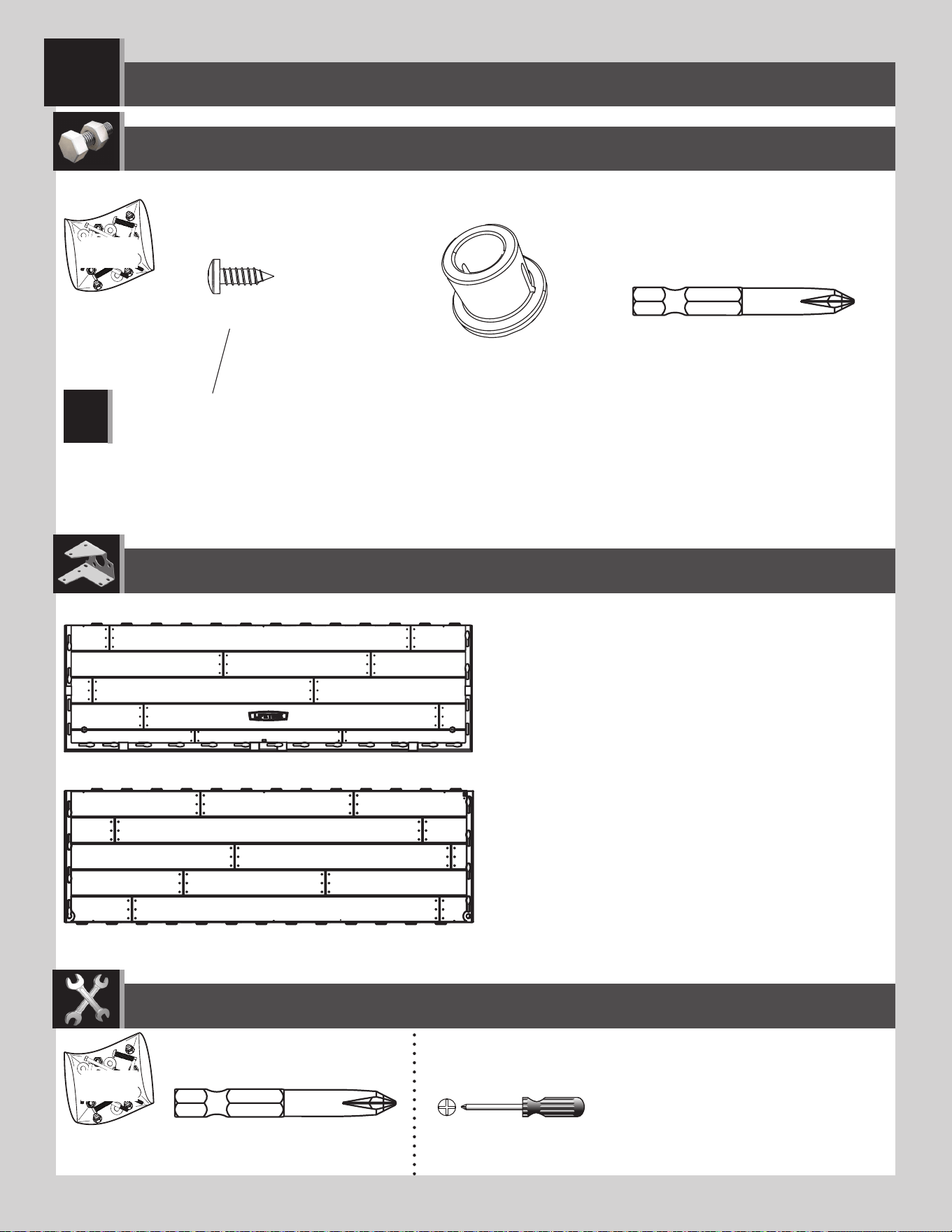
FLOOR ASSEMBLY / ASSEMBLAGE DU PLANCHER / ENSAMBLE DEL PISO
6
CUW (x2)
CUD (x3)
AHO (x2)
BQC (x24)
ADC (x1)
ADC (x1)
EFU
EFU
Plastic Parts / Pièces en plastique / Piezas de plástico
Hardware Bag / Sac de quincaillerie / Bolsa de herraje
TOOLS REQUIRED / OUTILS REQUIS / INSTRUMENTAL REQUERIDO
PARTS REQUIRED / PIÈCES REQUISES / PIEZAS REQUERIDAS
HARDWARE REQUIRED / QUINCAILLERIE REQUISE / HERRAJE REQUERIDO
Note: These Screws do not anchor the Floor; they only hold the Panels together.
Remarque : Ces vis n’ancrent pas le plancher ; ils ne servent que pour attacher les panneaux les uns aux autres.
Nota: Estos tornillos no anclan el piso; sirven sólo para sujetar los paneles los unos a los otros.
!
36
TOOLS AND HARDWARE REQUIRED / OUTILS ET QUINCAILLERIE REQUIS / INSTRUMENTAL Y HERRAJE REQUERIDOS
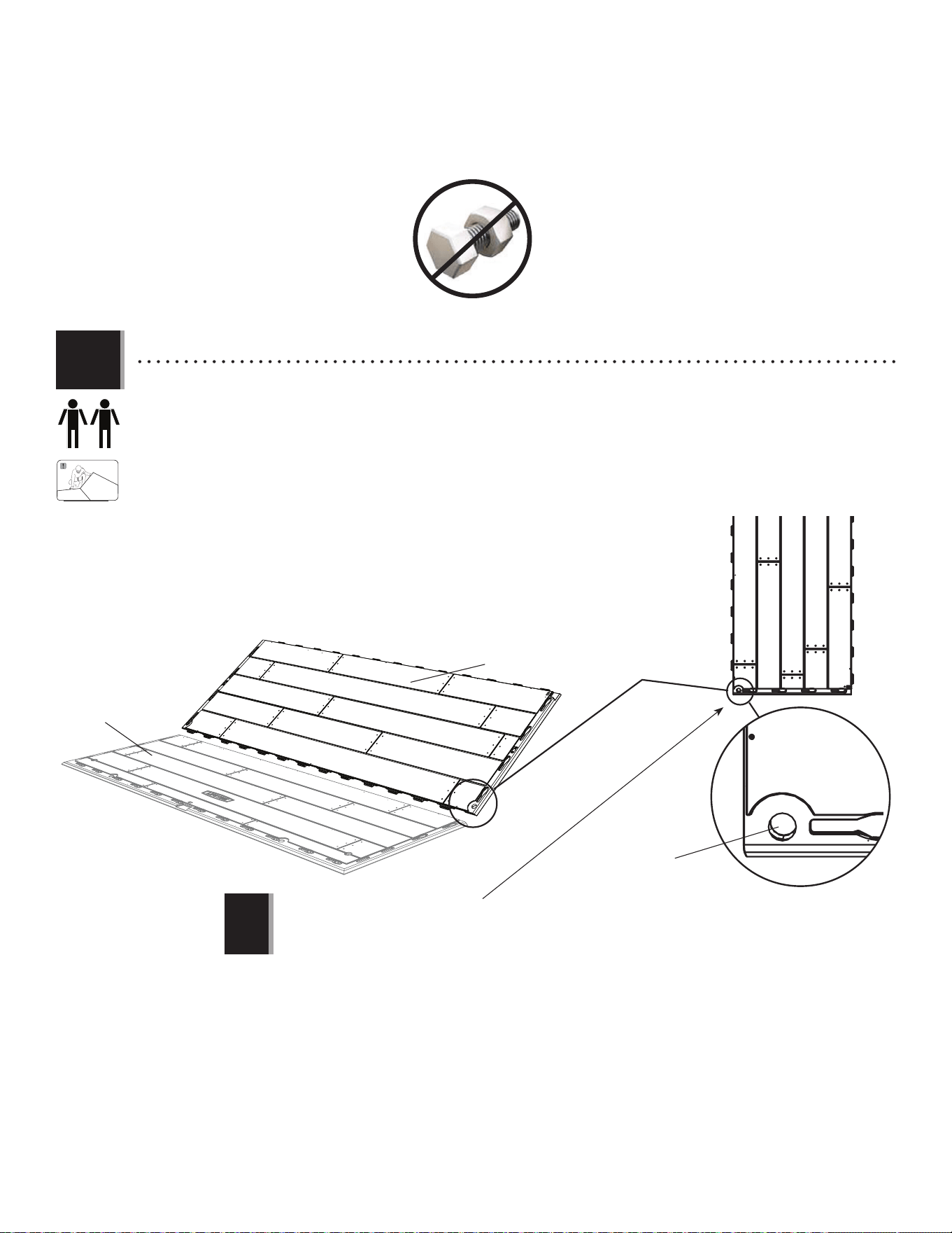
X SECTION 6 (CONTINUED) / SECTION 6 (SUITE) / SECCIÓN 6 (CONTINUACIÓN)
• Hold an Inner Floor Panel (CUD) at an angle, and slide the tabs along the edge underneath an Outer Floor Panel (CUW).
The tabs interlock. Lay the Panel fl at.
• Poser un panneau de plancher intérieur (CUD) à un angle, et faire glisser les languettes le long du bord au-dessus du
panneau de plancher extérieur (CUW). Les languettes s’enclenchent les uns les autres. Étendre-le par terre.
• Colocar un panel de piso interior (CUD) a un ángulo, y deslizar las lenguetas a lo largo del borde debajo el panel de
piso exterior (CUW). Las lengüetas se entrelazan las unas con las otras. Aplanarlo.
CUD
CUW
Hole / Trou / Agujero
Note: If the hole is not at this corner, turn the Panel 180°. The Left Door Hinge goes here later.
Remarque : Si le trou n’est pas ici, tourner le panneau 180°. La charnière de la porte gauche s’insère ici plus tard.
Nota: Si el agujero no está aquí, girar el panel 180°. La bisagra de la puerta izquierda se inserta aquí más tarde.
6.1
!
37
TOOLS AND HARDWARE REQUIRED / OUTILS ET QUINCAILLERIE REQUIS / INSTRUMENTAL Y HERRAJE REQUERIDOS
X SECTION 6 (CONTINUED) / SECTION 6 (SUITE) / SECCIÓN 6 (CONTINUACIÓN)
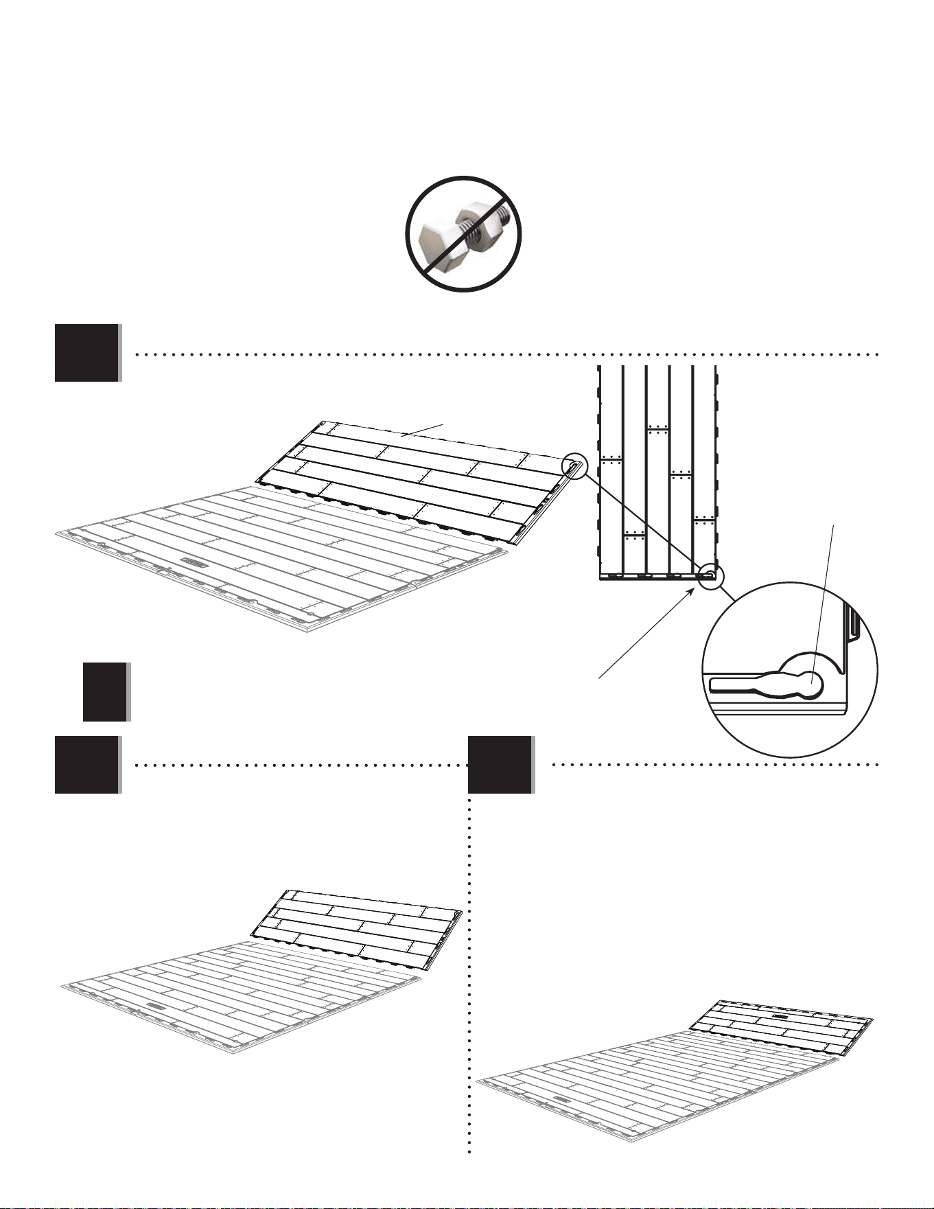
• Repeat the previous step.
• Répéter l’étape précédente.
• Repetir el paso anterior.
Note: If the hole is not at this corner, turn the Panel 180°. The Right Door Hinge goes here later.
Remarque : Si le trou n’est pas ici, tourner le panneau 180°. La charnière de la porte droite s’insère ici plus tard.
Nota: Si el agujero no está aquí, girar el panel 180°. La bisagra de la puerta derecha se inserta aquí más tarde.
CUD
Hole / Trou / Agujero
!
6.2
CUD
CUW
• Lay down another Inner Floor Panel (CUD).
• Poser un autre panneau de plancher intérieur (CUD).
• Colocar otro panel de piso interior (CUD).
6.3 6.4
• Hold an Outer Floor Panel (CUW) at an angle and
slide the tabs along the edge underneath the last
Inner Floor Panel. Lay Panel down fl at.
• Poser un panneau de plancher extérieur (CUW) à
un angle, et faire glisser les languettes le long du
bord au-dessus du dernier panneau de plancher
intérieur. Étendre-le par terre.
• Colocar un panel de piso exterior (CUW) a un
ángulo, y deslizar las lenguetas a lo largo del
borde debajo el último panel de piso interior.
Aplanar el panel.
38
TOOLS AND HARDWARE REQUIRED / OUTILS ET QUINCAILLERIE REQUIS / INSTRUMENTAL Y HERRAJE REQUERIDOS
X SECTION 6 (CONTINUED) / SECTION 6 (SUITE) / SECCIÓN 6 (CONTINUACIÓN)
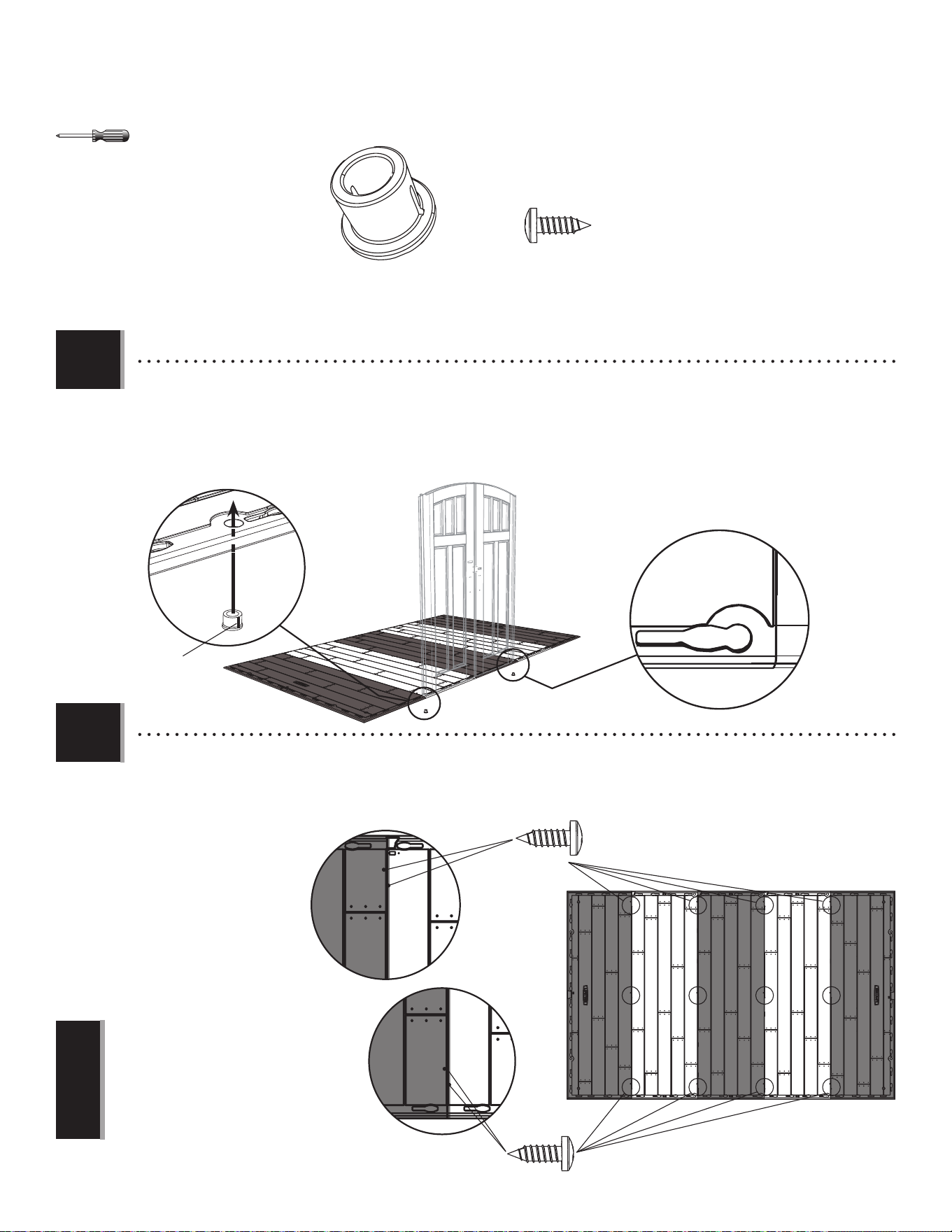
• Insert six (6) Screws (BQC) through the divots in the Floor Panels and into the tabs of the adjacent Floor Panels.
(The divots are near each seam of the Floor Panels.)
• Insérer six (6) vis (BQC) à travers les marques dans les panneaux de plancher et dans les languettes du panneaux
de plancher contigu. (Les marques se trouvent près de chaque jonction des panneaux de plancher.)
• Insertar seis (6) tornillos
(BQC) a través de las
marcas en los paneles
de piso y dentro de las
lengüetas de los paneles
de piso adyacentes. (Se
encuentran las marcas
cerca de cada juntura de
los paneles de piso.)
• Insert Bushings (AHO) through the holes in the 2nd and 3rd Floor Panels from the left. The slit in the Bushing should face
the front of the shed.
• Insérer les bagues (AHO) à travers les trous dans les 2e et 3e panneaux de plancher du bord gauche. La fente dans la
bague doit donner sur le bord avant de l’abri.
• Insertar los casquillos (AHO) a través de los agujeros en los 2º y 3º paneles de piso del borde izquierdo. La rendija en
el casquillo debe dar hacia el borde delantero de la caseta.
AHO (x2)
BQC (x24)
BQC
BQC
Note: These Screws do not anchor the Floor; they
only hold the Panels together.
Remarque : Ces vis n’ancrent pas le plancher ; ils
ne servent que pour attacher les panneaux les uns
aux autres.
Nota: Estos tornillos no anclan el piso; sirven sólo
para sujetar los paneles los unos a los otros.
!
6.5
6.6
Front Edge
Bord avant
Borde delantero
AHO
• Slit
• Fente
• Rendija
1
2
3
4
5
39
WALL ASSEMBLY / ASSEMBLAGE DES MURS / ENSAMBLE DE LOS MUROS
7
67 3/4 in/po (≈1,72 m)
AHD (x8)
AGL (x2)
AGW (x2)
CKK (x1)
CKN (x1)
AFM (x10)
ADZ (x110)
AIW (x1)
FFZ
Metal Parts / Pièces en métal / Piezas de metal
Plastic Parts / Pièces en plastique / Piezas de plástico
Hardware Bag / Sac quincaillerie / Bolsa de herraje
TOOLS REQUIRED / OUTILS REQUIS / INSTRUMENTAL REQUERIDO
PARTS REQUIRED / PIÈCES REQUISES / PIEZAS REQUERIDAS
HARDWARE REQUIRED / QUINCAILLERIE REQUISE / HERRAJE REQUERIDO
AHH (x1)
40
TOOLS AND HARDWARE REQUIRED / OUTILS ET QUINCAILLERIE REQUIS / INSTRUMENTAL Y HERRAJE REQUERIDOS
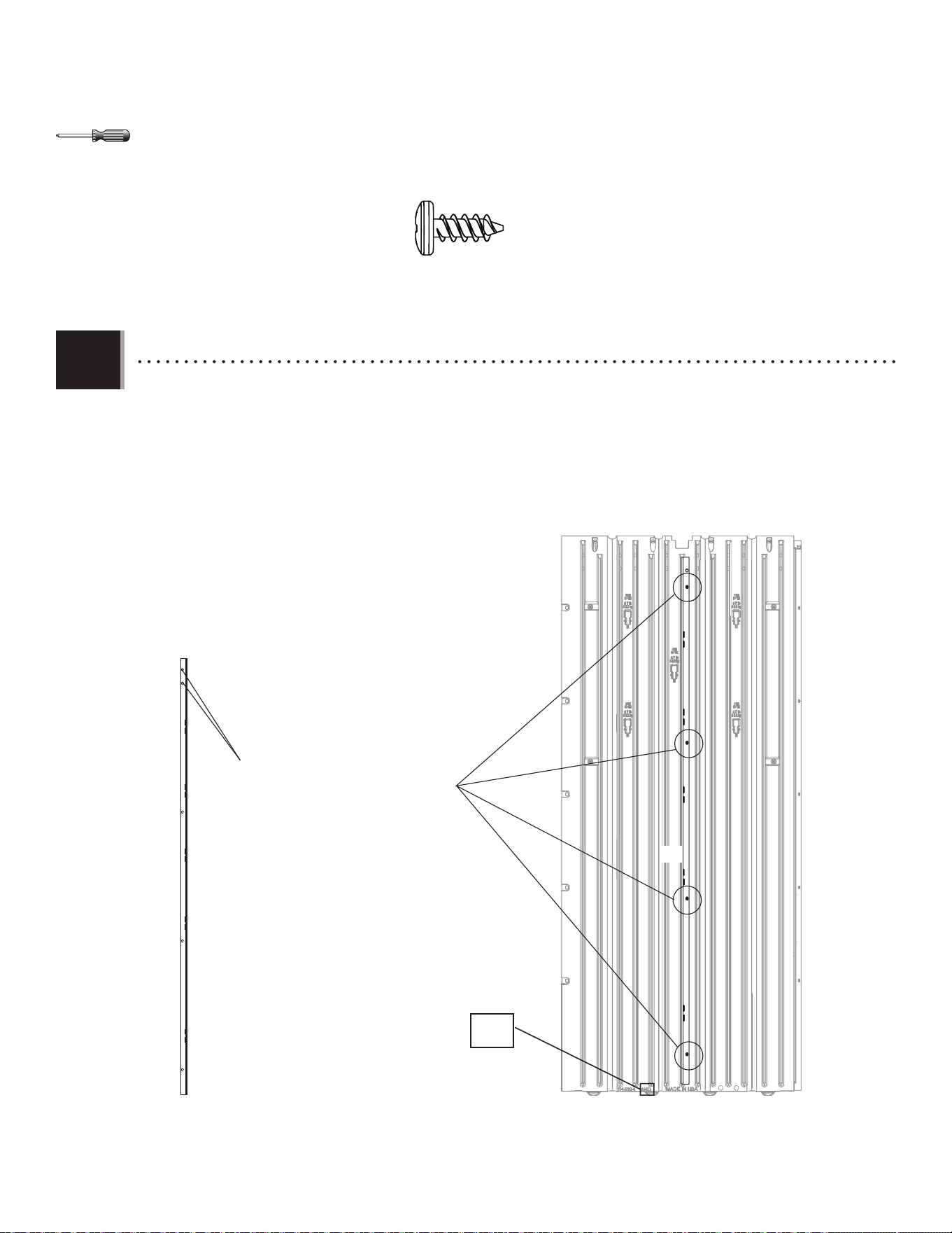
X SECTION 7 (CONTINUED) / SECTION 7 (SUITE) / SECCIÓN 7 (CONTINUACIÓN)
7.1
ADZ (x32)
• Insert a Wall Channel (AFM) into the groove just below the notch of each Wall Panel (AHD) as shown. Attach with four
(4) Screws (ADZ) at the locations shown.
• Insérer un support mural (AFM) dans la rainure juste au-dessous de l’encoche dans chaque panneau mural (AHD)
comme illustré. Attacher-le à l’aide de quatre (4) vis (ADZ) aux endroits indiqués.
• Insertar un soporte mural (AFM) en la ranura apenas abajo la muesca en cada panel mural (AHD) como se muestra.
Sujetarlo usando cuatro (4) tornillos (ADZ) a las ubicaciones indicadas.
AFM
AFM
ADZ
• The two holes go at the top.
• Les deux trous vont en haut.
• Los dos agujeros van hacia arriba.
AHD
4141
TOOLS AND HARDWARE REQUIRED / OUTILS ET QUINCAILLERIE REQUIS / INSTRUMENTAL Y HERRAJE REQUERIDOS
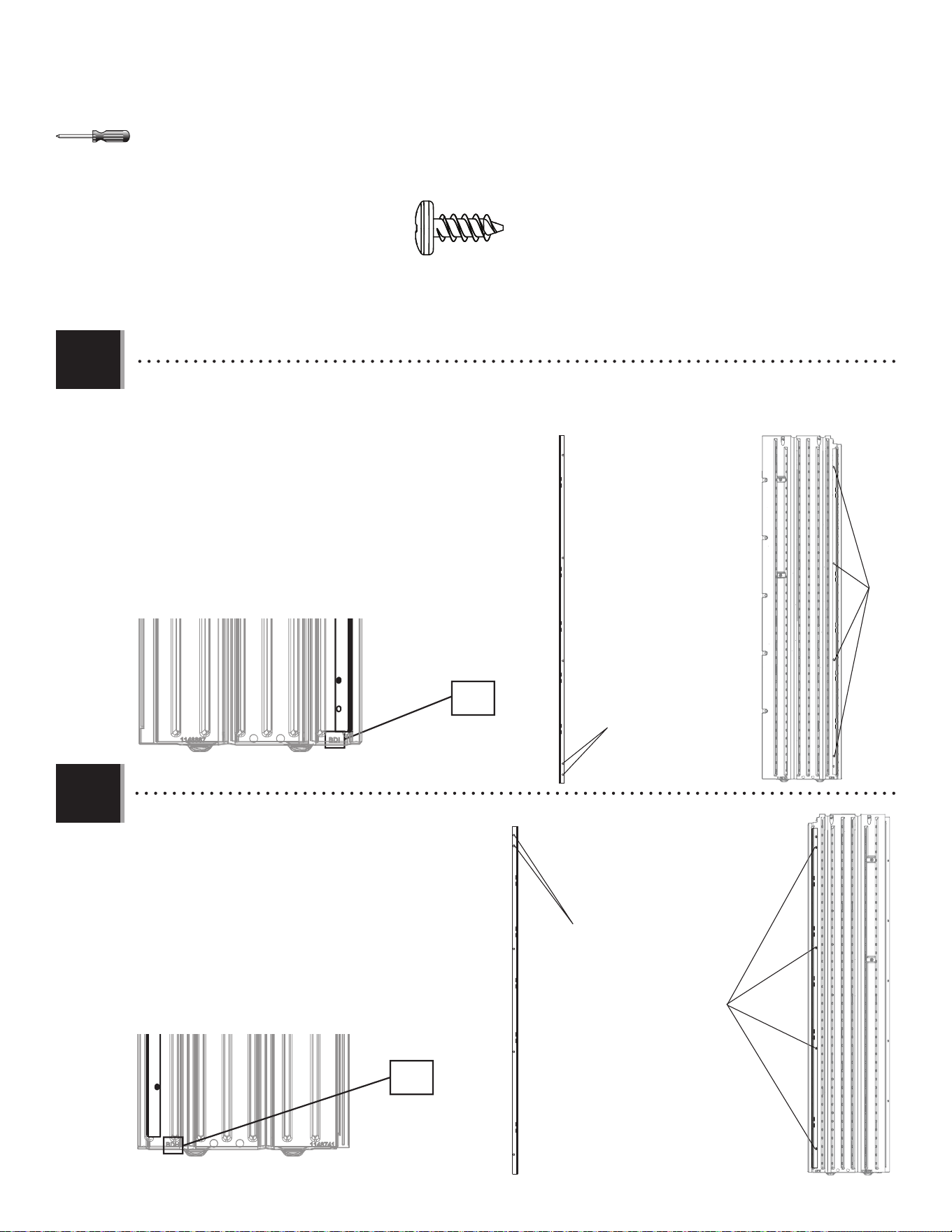
X SECTION 7 (CONTINUED) / SECTION 7 (SUITE) / SECCIÓN 7 (CONTINUACIÓN)
• Insert a Wall Channel (AFM) into the fi rst groove on the back of
the Right Narrow Wall Panel (CKN) as shown. Attach with just four
(4) Screws (ADZ).
• Insérer un support mural (AFM) dans la première rainure du
panneau mural étroit droit (CKN) comme illustré. Attacher-le à
l’aide de quatre (4) vis (ADZ) seulement.
• Insertar un soporte mural (AFM) en la primera ranura del panel
mural angosto derecho (CKN) como se muestra. Sujetarlo usando
sólo cuatro (4) tornillos (ADZ).
• Insert a Wall Channel (AFM) into the fi rst groove on the
back of the Left Narrow Wall Panel (CKK) as shown. Attach
with just four (4) Screws (ADZ).
• Insérer un support mural (AFM) dans la première rainure
du panneau mural étroit gauche (CKK) comme illustré.
Attacher-le à l’aide de quatre (4) vis (ADZ) seulement.
• Insertar un soporte mural (AFM) en la primera ranura
del panel mural angosto izquierdo (CKK) como se muestra.
Sujetarlo usando sólo cuatro (4) tornillos (ADZ).
7.2
7.3
AFM
ADZ
CKK
• The two holes go at the top.
• Les deux trous vont en haut.
• Los dos agujeros van hacia arriba.
CKN
CKK
AFM
ADZ
CKN
• The two holes go at the bottom.
• Les deux trous vont en bas.
• Los dos agujeros van hacia abajo.
ADZ (x8)
4242
TOOLS AND HARDWARE REQUIRED / OUTILS ET QUINCAILLERIE REQUIS / INSTRUMENTAL Y HERRAJE REQUERIDOS
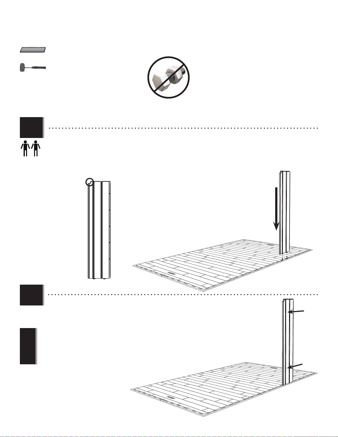
X SECTION 7 (CONTINUED) / SECTION 7 (SUITE) / SECCIÓN 7 (CONTINUACIÓN)
AIW (x1)
CKN
CKN
• Slide the Panel to the left.
• Faire glisser le panneau à gauche.
• Deslizar el panel a la izquierda.
Nota: You may need to use a rubber mallet and the fl at side of the Wood Block (AIW) to
gently tap the Wall Panel into place.
Remarque : Si besoin, utiliser un maillet en caoutchouc et le côté plat du bloc en bois (AIW)
pour couper doucement en place le panneau mural.
Nota: Si es necesario, usar el mazo de goma y el lado plano del bloque de madera (AIW)
para golpear suavemente en su lugar el panel mural.
!
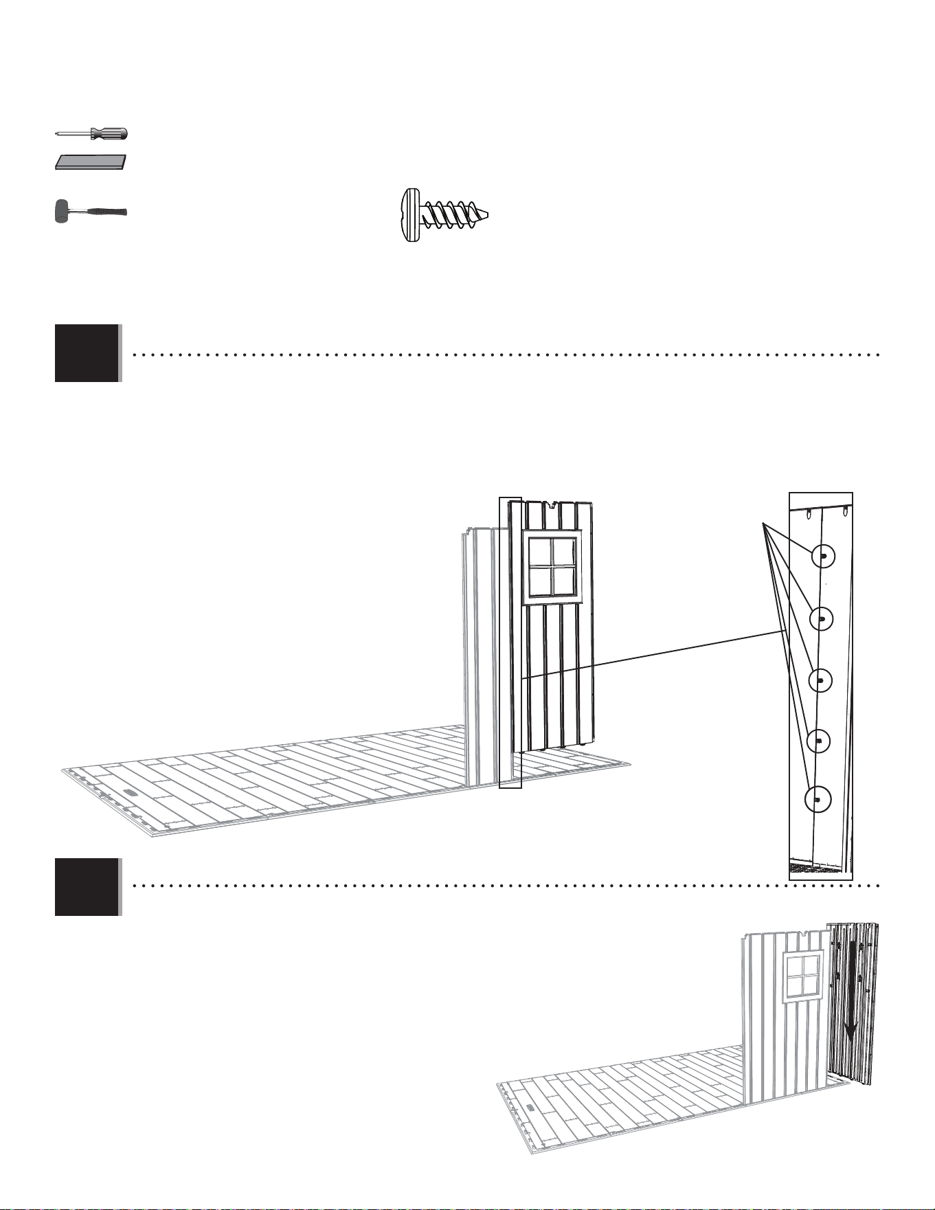
• Insert tabs at the bottom of the Right Narrow Wall Panel (CKN) into the seventh and eighth slots from the front, right
corner of the Floor.
• Insérer les languettes au bord inférieur du panneau mural étroit droit (CKN) dans les septième et huitième rainures du
coin droit du plancher.
• Insertar las lengüetas al borde inferior del panel mural angosto derecho (CKN) en las septima y octava ranuras de la
esquina derecha del piso.
7.4
7.5
4343
TOOLS AND HARDWARE REQUIRED / OUTILS ET QUINCAILLERIE REQUIS / INSTRUMENTAL Y HERRAJE REQUERIDOS
X SECTION 7 (CONTINUED) / SECTION 7 (SUITE) / SECCIÓN 7 (CONTINUACIÓN)
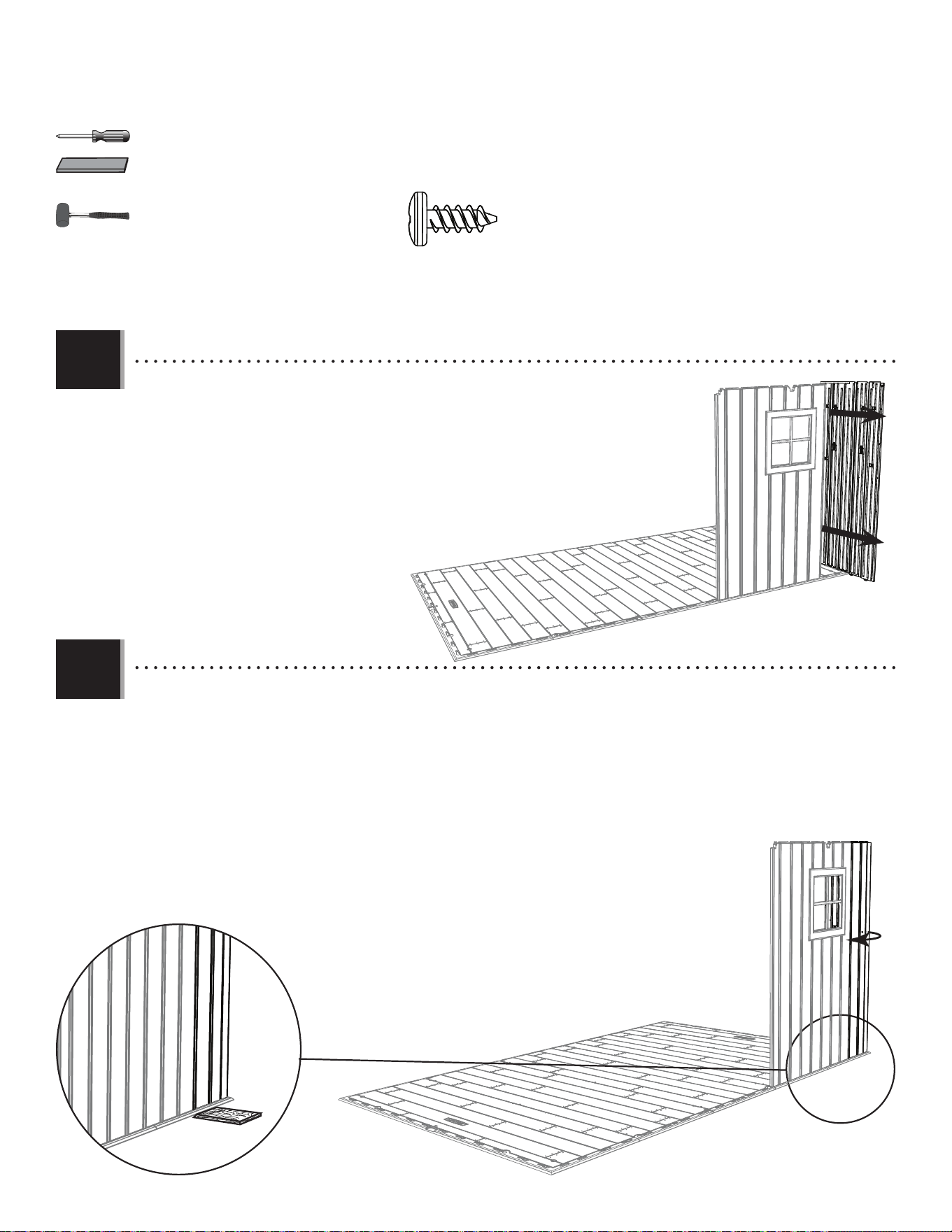
• Insert the four tabs at the bottom of the Window Wall Panel (AHH) into the fl oor slots next to the Narrow Wall Panel,
and slide the Panel to the left. Align the fi ve holes, and secure the two Panels using fi ve (5) Screws (ADZ).
• Insérer les quatre languettes au bord inférieur du panneau mural avec fenètre (AHH) dans les rainures à côté du
panneau mural étroit droit, et faire glisser le panneau à gauche. Aligner les cinq trous, et attacher bien les deux
panneaux à l’aide de cinq (5) vis (ADZ).
• Insertar las cuatro lengüetas al borde inferior del panel mural con ventana (AHH) en las ranuras a lado del panel
mural angosto derecho, y deslizar el panel a la izquierda. Alinear los cinco agujeros, y sujetar los dos paneles
usando cinco (5) tornillos (ADZ).
AHH
ADZ
ADZ (x5)
AIW (x1)
• Insert tabs at the bottom of the Corner Panel (AGW) into the fi rst two slots along the right
edge of the Floor, and slide the Panel toward the front of the Floor.
• Insérer les languettes au bord inférieur du panneau angulaire (AGW) dans les premières
rainures le long du bord droit du plancher, et faire glisser le panneau vers la partie avant
de l’abri.
• Insérer las lengüetas al borde inferior del panel angular (AGW) en las primeras dos ranuras
a lo largo del borde derecho del piso, y deslizar el panel hacia la parte delantera de la
caseta.
AGW
7.6
7.7
4444
TOOLS AND HARDWARE REQUIRED / OUTILS ET QUINCAILLERIE REQUIS / INSTRUMENTAL Y HERRAJE REQUERIDOS
X SECTION 7 (CONTINUED) / SECTION 7 (SUITE) / SECCIÓN 7 (CONTINUACIÓN)
• Insert tabs at the bottom of the Corner Panel (AGW) into the fi rst two slots along the right
edge of the Floor, and slide the Panel toward the front of the Floor.
• Insérer les languettes au bord inférieur du panneau angulaire (AGW) dans les preimières
rainures le long du bord droit du plancher, et faire glisser le panneau vers la partie
avant de l’abri.
• Insertar las lengüetas al borde inferior del panel angular (AGW) en las primeras dos
ranuras a lo largo del borde derecho del piso, y deslizar el panel hacia la parte
delantera de la caseta.
• Bend the Corner Panel as shown, and pull down to snap the tabs into the fi rst two slots from the right corner of
the Floor. Place the Wood Block (AIW) underneath the Floor and directly underneath the tab being inserted to help
with insertion. Secure the two Panels using fi ve (5) Screws (ADZ).
• Plier le panneau angulaire comme illustré, tirer le panneau vers le bas, et insérer les languettes dans les
premières deux encoches du coin avant droit. Pour aider avec l’insertion, mettre le bloc en bois (AIW) sous le
plancher et directement sous l’onglet à insérer. Attacher bien les deux panneaux à l’aide de cinq (5) vis (ADZ).
• Desplegar el panel angular como se muestra, tirar para abajo el panel, e insertar las
lengüetas en las dos primeras muescas de la esquina delantera derecha. Para ayudar con la
inserción, colocar el bloque de madera (AIW) debajo el piso y directamente debajo la lengüeta a
insertar. Sujetar los dos paneles usando cinco (5) tornillos (ADZ).
AIW
ADZ (x5)
AIW (x1)
7.8
7.9
4545
TOOLS AND HARDWARE REQUIRED / OUTILS ET QUINCAILLERIE REQUIS / INSTRUMENTAL Y HERRAJE REQUERIDOS
X SECTION 7 (CONTINUED) / SECTION 7 (SUITE) / SECCIÓN 7 (CONTINUACIÓN)
ADZ (x10)
AIW (x1)
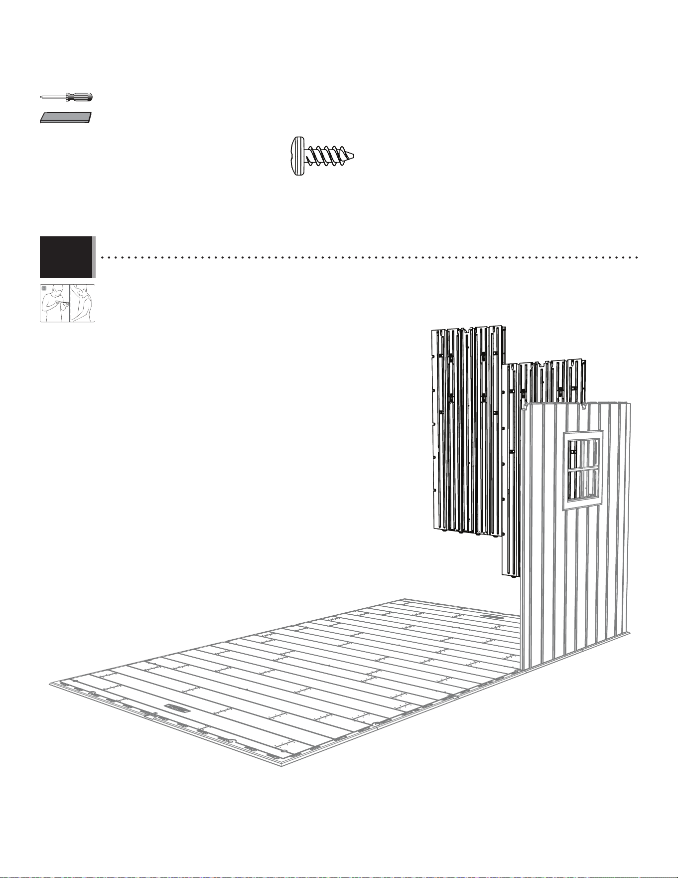
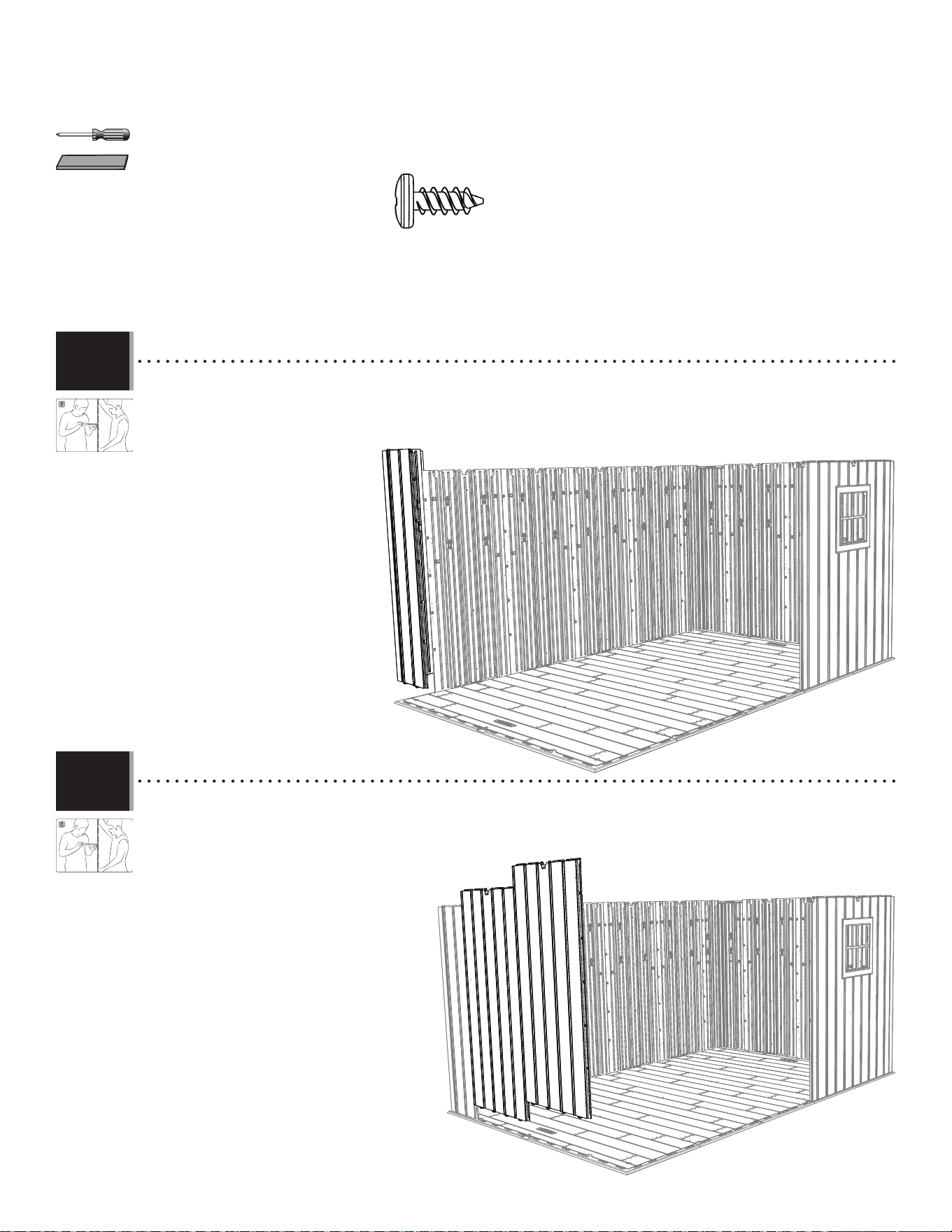
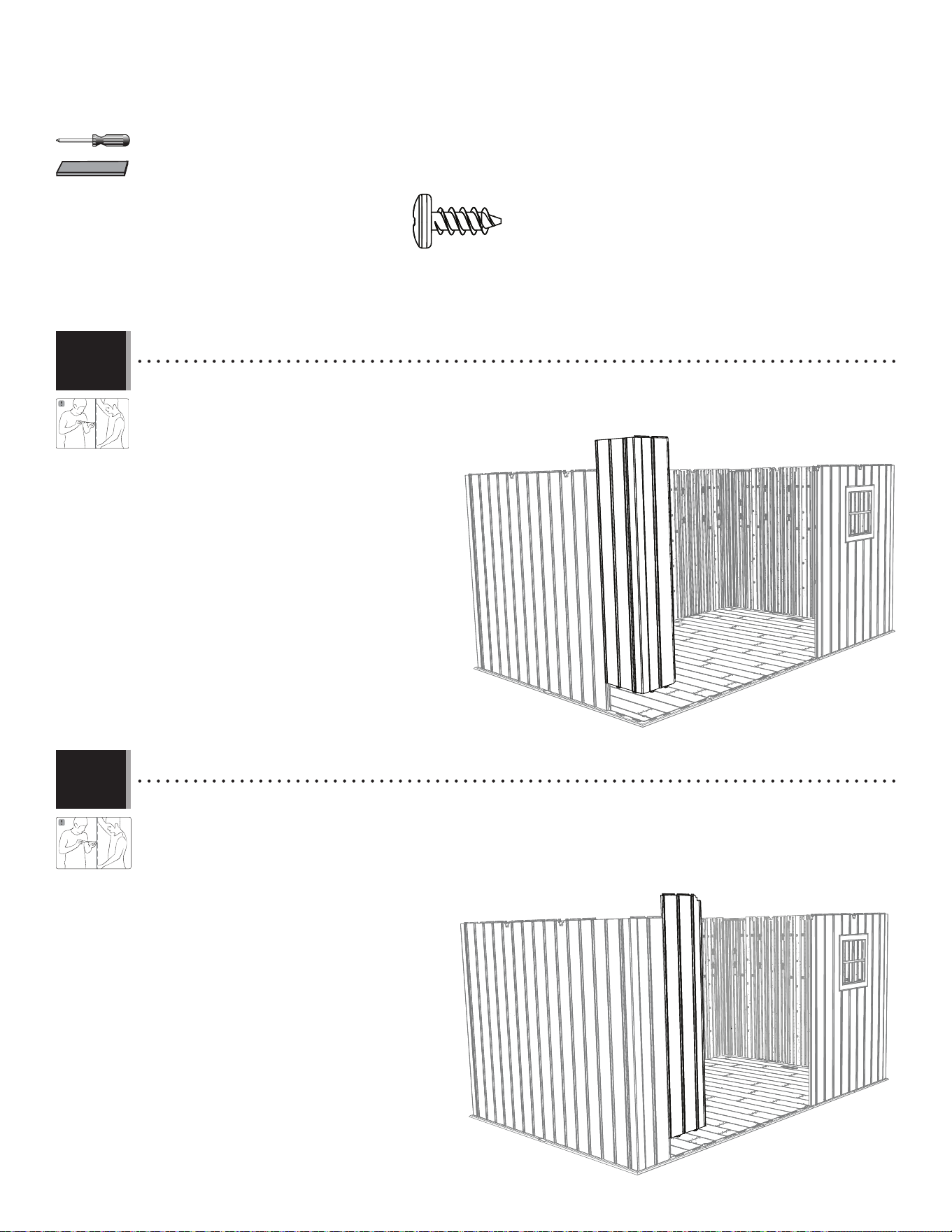
• Insert two (2) Wall Panels (AHD), and secure using fi ve (5) Screws (ADZ) each.
• Insérer deux (2) panneaux muraux (AHD), et attacher-les l’un à l’autre à l’aide de cinq (5) vis (ADZ) chacun.
• Insertar dos (2) paneles de pared (AHD), y sujetarlos usando cinco (5) tornillos (ADZ) cada uno.
AHD
AHD
7.10
4646
TOOLS AND HARDWARE REQUIRED / OUTILS ET QUINCAILLERIE REQUIS / INSTRUMENTAL Y HERRAJE REQUERIDOS
X SECTION 7 (CONTINUED) / SECTION 7 (SUITE) / SECCIÓN 7 (CONTINUACIÓN)
AHD
AHD
AHD
AHD
ADZ (x25)
AIW (x1)
AGL
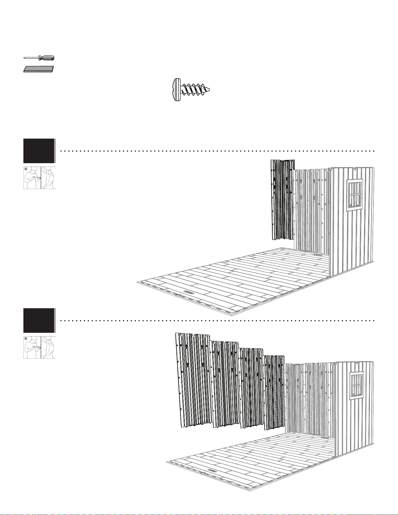
• For the right, rear Corner Panel (AGL), repeat the step you did for the
right, front Corner Panel.
• Pour le panneau angulaire (AGL) arrière droit, répéter les étapes que
réalizées pour le panneau angulaire avant droit.
• Para el panel angular (AGL) trasero derecho, repetir los pasos que se
efectuaron para el panel angular delantero derecho.
• Insert four (4) Wall Panels (AHD) along
the rear edge of the Floor, and secure
using fi ve (5) Screws (ADZ) each.
• Inérérer quatre (4) panneaux muraux
(AHD) le long du bord arrière du
plancher, et attacher-les l’un à l’autre à
l’aide de cinq (5) vis (ADZ) chacun.
• Insertar cuatro (4) paneles de pared
(AHD) a lo largo del borde trasero del
piso, y sujetarlos usando cinco (5)
tornillos (ADZ) cada uno.
7.11
7.12
47
BDK (x1)
AGI (x2)
AGH (x2)
BDC (x1)
BDJ (x1)
AFV (x2)
AGQ (x8)
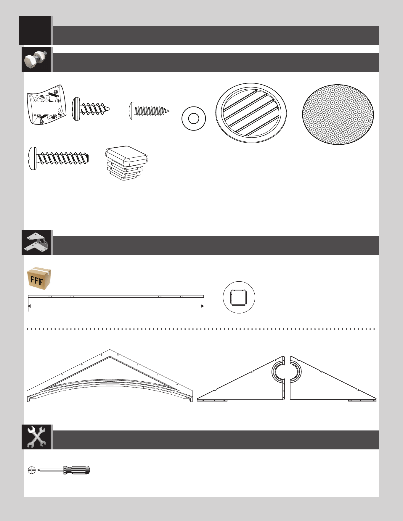
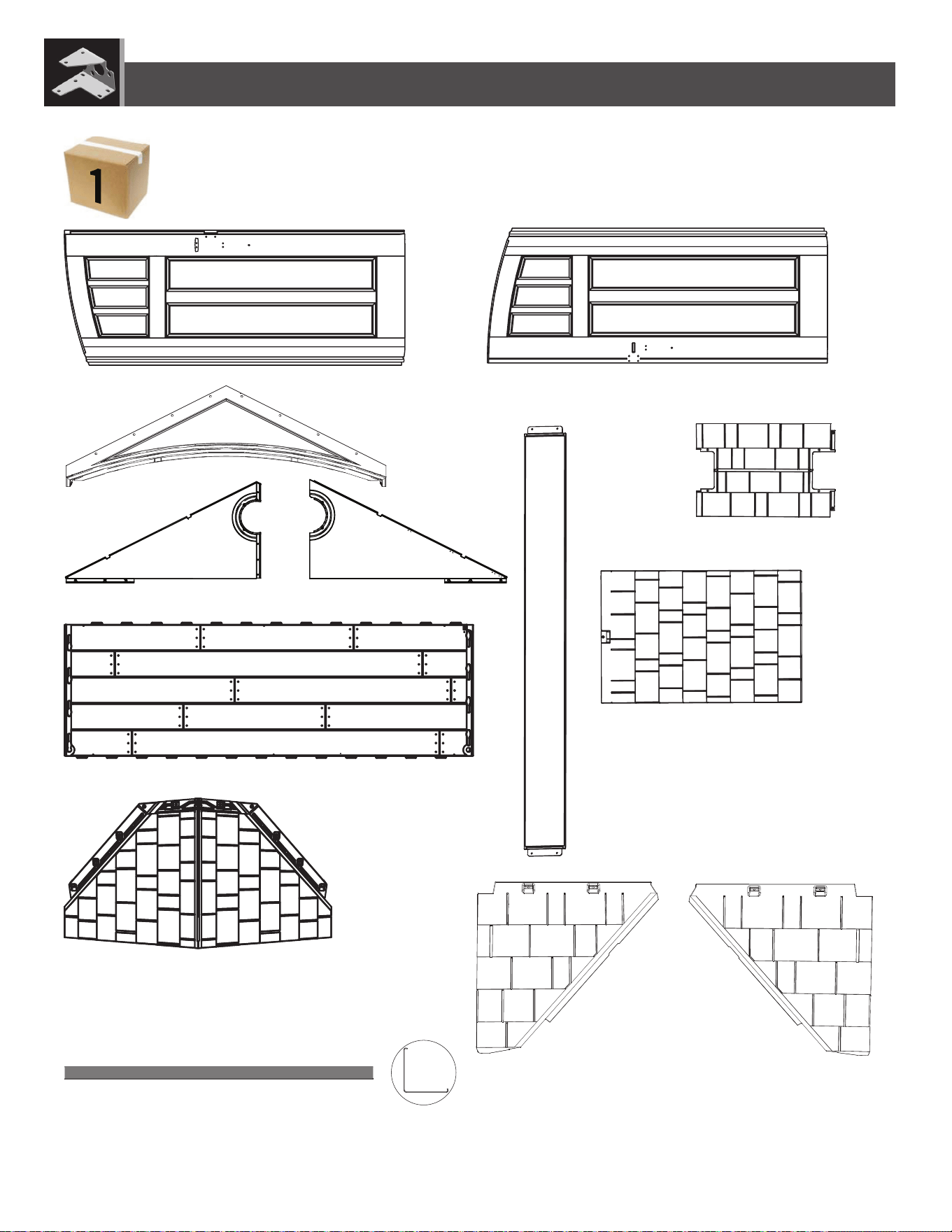
CONTENTS OF BOX 1 / CONTENIDO DE LA CAJA 1 / CONTENU DE LA BOÎTE 1
PARTS IDENTIDIER / IDENTIFICADOR DE PIEZAS / IDENTIFICATEUR DE PIÈCES
Remove This Section / Enlevez cette section / Reitire esta sección
CUD (x3)
DRA (x1)
BDR (x1)
CVG (x4)
BDS (x1)
AFY (117) (x4)
48
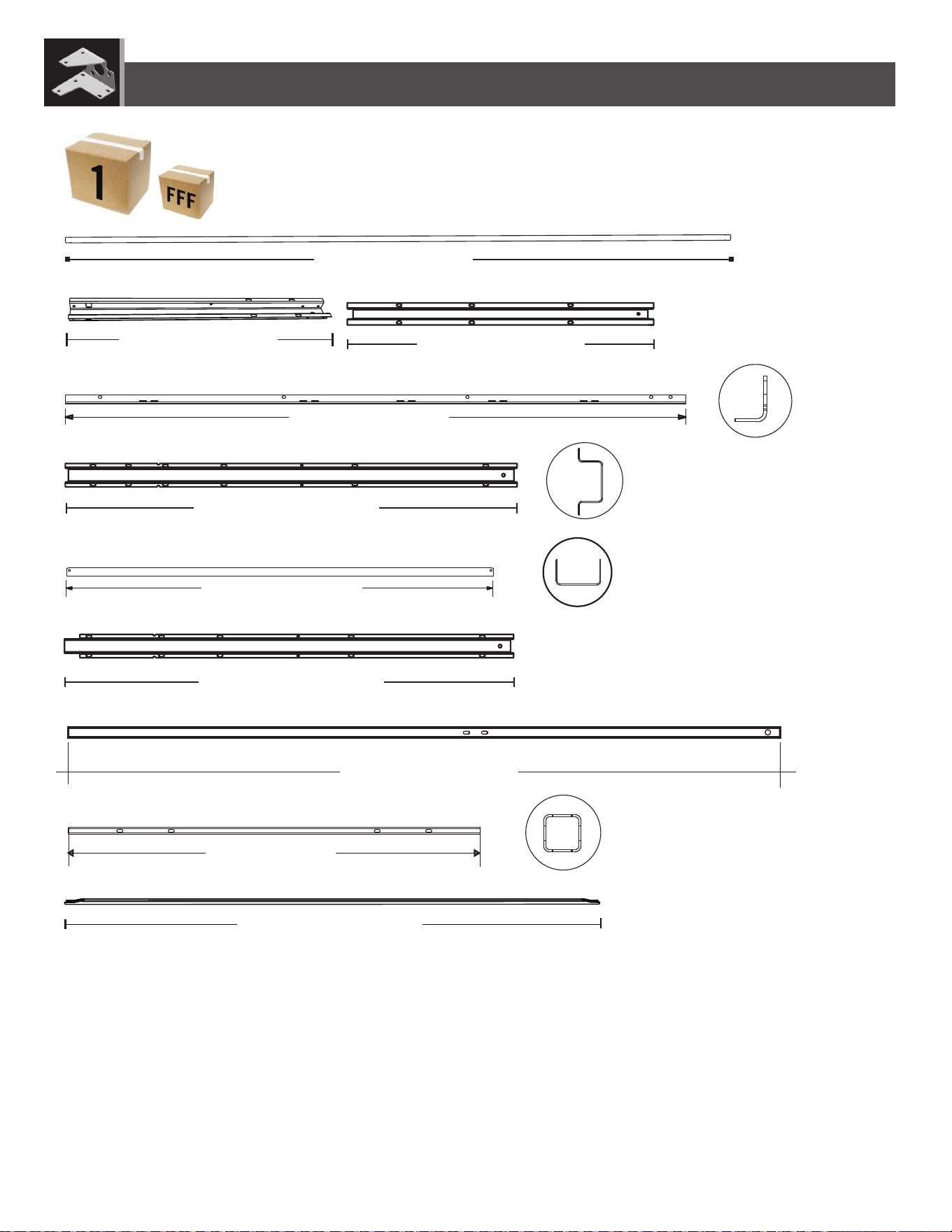
48 in/po (≈1,22 m)
67 3/4 in/po (≈1,72 m)
AFG (x4)
DSQ (x2)
BDD (x1)
DSP (x1)
EDW (x2)
AFM (x10)
CRE (x2)
DSM (x1)
DSO (x1)
CONTENTS METAL KIT / CONTENIDO DEL KIT DE PIEZAS DE METAL / CONTENU DU KIT DE PIÈCES EN MÉTAL
PARTS IDENTIDIER / IDENTIFICADOR DE PIEZAS / IDENTIFICATEUR DE PIÈCES
DSR (x5)
50 9/16 in/po (≈1,28 m)
Remove This Section / Enlevez cette section / Reitire esta sección
74 1/2 in/po (≈1,89 m)
50 9/16 in/po (≈1,28 m)
34 1/8 in/po (≈86,7 cm)
74 5/8 in/po (≈1,90 m)
46 in/po (≈1,17 m)
58 1/4 in/po (≈1,47 m)
25 7/8 in/po (≈65,7 cm)
49
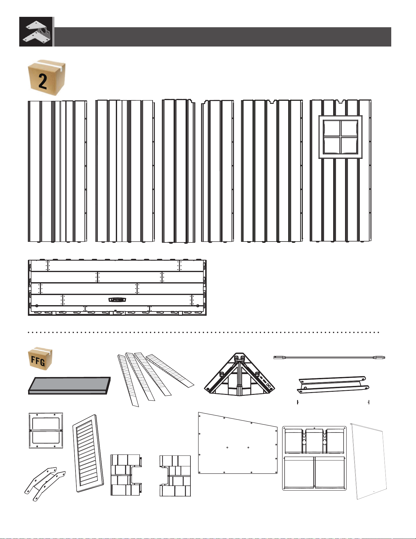
AHD (x8)
CKK (x1)
CKN (x1)
AHH (x1)
AHE (x1)
EDI (x1)
DSN (x1)
AIX (x4)
AIW (x1)
CONTENTS OF BOX 2 / CONTENIDO DE LA CAJA 2 / CONTENU DE LA BOÎTE 2
CONTENTS OF SMALL PARTS BOX / CONTENIDO DE LA CAJA DE PIEZAS PEQUEÑAS / CONTENU DE LA BOÎTE DE PETITES PIÈCES
PARTS IDENTIDIER / IDENTIFICADOR DE PIEZAS / IDENTIFICATEUR DE PIÈCES
Remove This Section / Enlevez cette section / Reitire esta sección
AGL (x2)
AGW (x2)
AFL (x8)
AHC (x5)
AYI (x2)
DRB (x1)
CUW (x2)
DHN (x2)
8 7/16 in/po (≈21,4 cm)
AIP (x4)
AGG (115) (x1)
AFW (116) (x1)
50
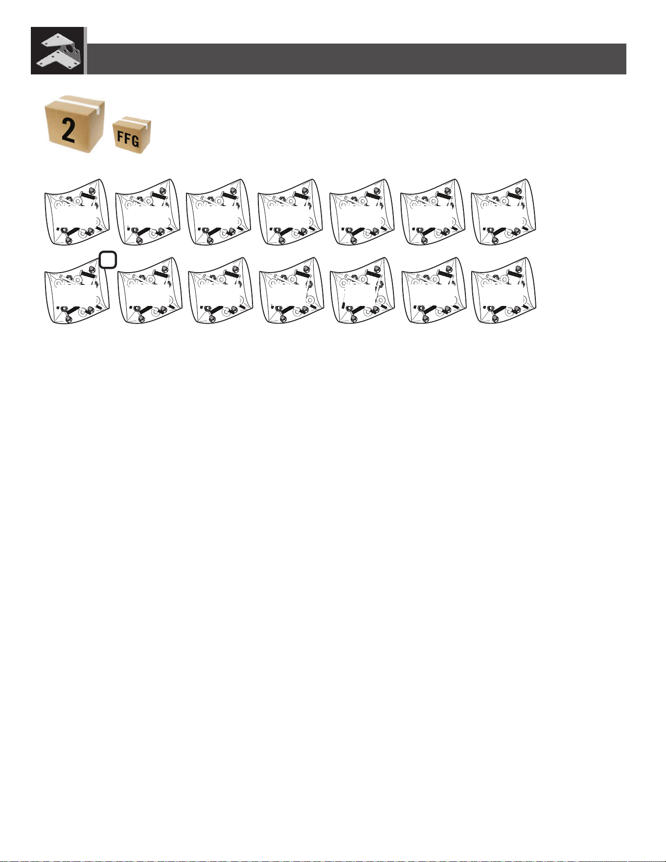
CONTENTS OF BOX 2 / CONTENIDO DE LA CAJA 2 / CONTENU DE LA BOÎTE 2
HARDWARE BAGS / BOLSAS DE HERRAJE / SACS DE QUINCAILLERIE
PARTS IDENTIDIER / IDENTIFICADOR DE PIEZAS / IDENTIFICATEUR DE PIÈCES
Remove This Section / Enlevez cette section / Reitire esta sección
FFX
FGA
BJI
EFU
FDN
ECT
BEJ EDM EDH
FFZ
FFY
BHH
EDGDHL
2
5151
TOOLS AND HARDWARE REQUIRED / OUTILS ET QUINCAILLERIE REQUIS / INSTRUMENTAL Y HERRAJE REQUERIDOS
X SECTION 7 (CONTINUED) / SECTION 7 (SUITE) / SECCIÓN 7 (CONTINUACIÓN)
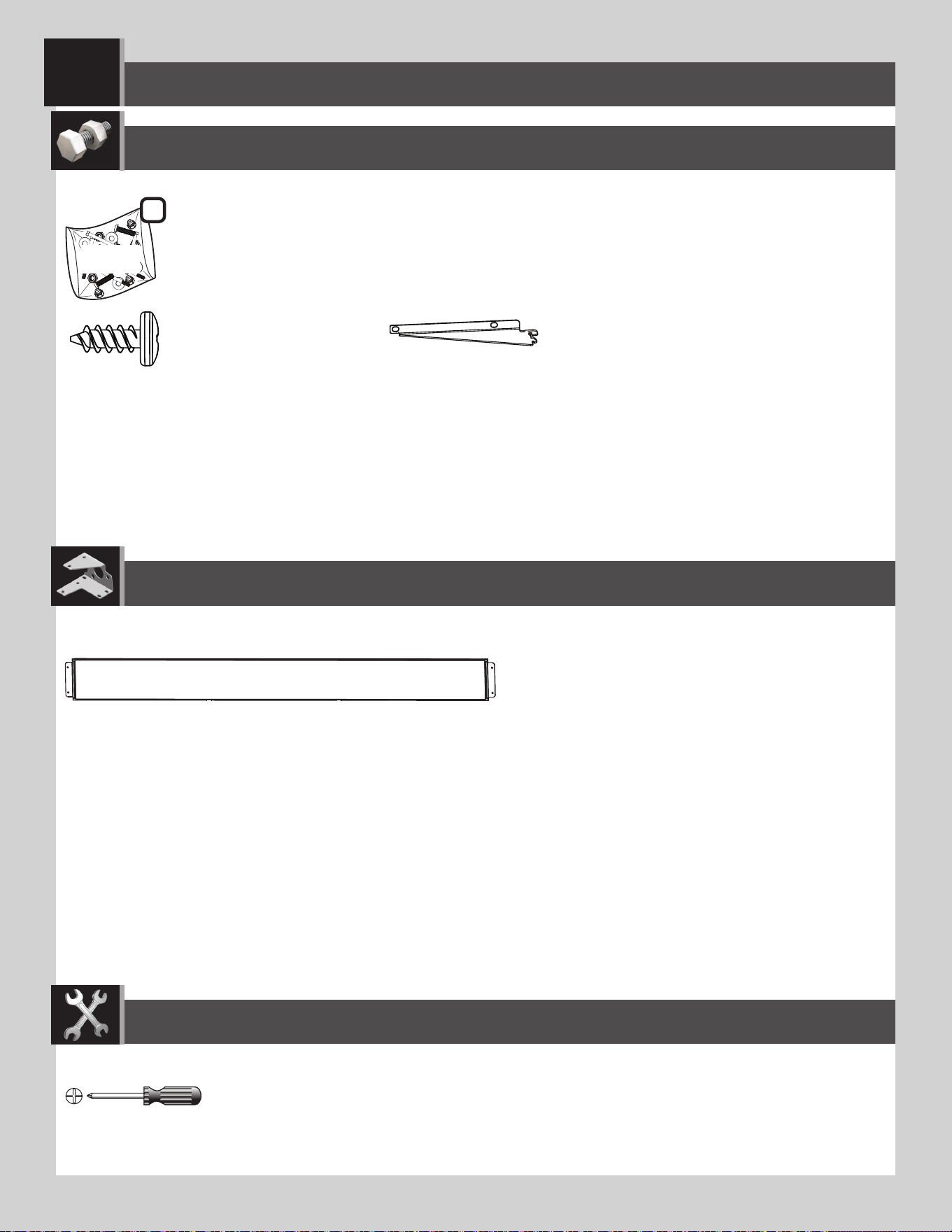
• Insert two (2) Wall Panels (AHD), and secure using fi ve (5) Screws (ADZ) each.
• Insérer deux (2) panneaux muraux (AHD), et attacher-les l’un à l’autre à l’aide de cinq (5) vis (ADZ) chacun.
• Insertar dos (2) paneles de pared (AHD), y sujetarlos usando cinco (5) tornillos (ADZ) cada uno.
ADZ (x15)
AGW
AHD
AHD
AIW (x1)
• For the left, rear Corner Panel (AGW), attach it to the Floor similar to the way you did the previous Corner Panels.
• Pour le panneau angulaire (AGW) arrière gauche, attacher-le au plancher d’une manière similaire aux panneaux
angulaires précédents.
• Para el panel angular (AGW) trasero
izquierdo, fi jarlo al piso de una
manera similar a los paneles
angulares anteriores.
7.13
7.14
5252
TOOLS AND HARDWARE REQUIRED / OUTILS ET QUINCAILLERIE REQUIS / INSTRUMENTAL Y HERRAJE REQUERIDOS
X SECTION 7 (CONTINUED) / SECTION 7 (SUITE) / SECCIÓN 7 (CONTINUACIÓN)
ADZ (x10)
AIW (x1)
AGL
• For the left, front Corner Panel (AGL), attach it to
the Floor similar to the way you did the previous
Corner Panels.
• Pour le panneau angulaire (AGL) avant gauche,
attacher-le au plancher d’une manière similaire
aux panneaux angulaires précédents.
• Para el panel angular (AGL) delantero izquierdo,
fi jarlo al piso de una manera similar a los
paneles angulares anteriores.
CKK
• Insert tabs at the bottom of the Left Narrow Wall Panel (CKK) into the third and fourth slots from the front, right corner
of the Floor. Slide the Panel to the left. Secure the two Panels using fi ve (5) Screws (ADZ).
• Insérer les languettes au bord inférieur du panneau mural étroit gauche (CKK) dans les troisième et quatrième
rainures du coin droit du plancher. Faire glisser
le panneau à gauche. Attacher bien les deux
panneaux à l’aide de cinq (5) vis (ADZ).
• Insertar las lengüetas al borde inferior del
panel mural angosto izquierdo (CKK) en las tercera y
quarta ranuras de la esquina derecha del piso.
Deslizar el panel a la izquierda. Sujetar los dos
paneles usando cinco (5) tornillos (ADZ).
7.15
7.16
53
SHELVING INSTALLATION / INSTALACIÓN DE LA ESTANTERÍA / INSTALLATION DU RAYONNAGE
8
ADZ (x28)
AIY (x4)
AFV (x2)
BHH
Plastic Parts / Piezas de plástico / Pièces en plastique
Hardware Bag / Bolsa de herraje / Sac de quincaillerie
TOOLS REQUIRED / INSTRUMENTAL REQUERIDO / OUTILS REQUIS
PARTS REQUIRED / PIEZAS REQUERIDAS / PIÈCES REQUISES
HARDWARE REQUIRED / HERRAJE REQUERIDO / QUINCAILLERIE REQUISE
2

54
TOOLS AND HARDWARE REQUIRED / INSTRUMENTAL Y HERRAJE REQUERIDOS / OUTILS ET QUINCAILLERIE REQUIS
X SECTION 8 (CONTINUED) / SECCIÓN 8 (CONTINUACIÓN) / SECTION 8 (SUITE)
8.1
• Insert the Shelf Brackets (AIY) into the slots in the Wall/Shelf Support Channels. The Brackets must be at the same height.
• Insérer les équerres (AIY) dans les fentes dans les canaux de support pour les murs/étagères. Les équerres doivent
être à la même hauteur.
• Insertar las escuadras (AIY) en las rajas en los canales de soporte para las paredes/estantes. Las escuadras deben estar
a la misma altura.
AIY
55
TOOLS AND HARDWARE REQUIRED / INSTRUMENTAL Y HERRAJE REQUERIDOS / OUTILS ET QUINCAILLERIE REQUIS
X SECTION 8 (CONTINUED) / SECCIÓN 8 (CONTINUACIÓN) / SECTION 8 (SUITE)
ADZ (x4)
AFV
50 lb. (23 kg)
!
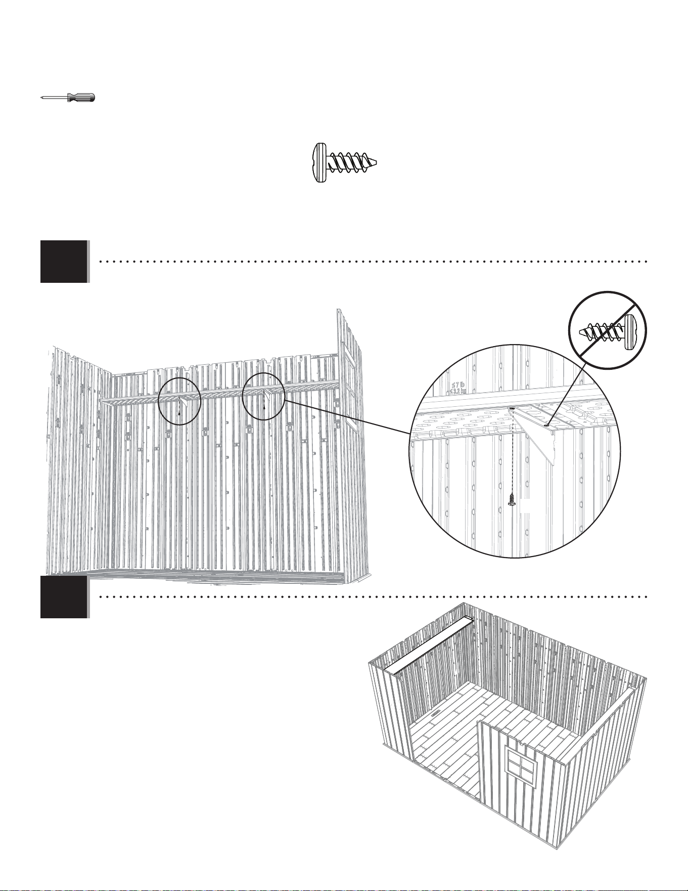
• Fold the fl aps on the ends of the Shelf (AFV) up,
and set the Shelf onto the Brackets. The notches along
the long edge should be against the rear wall.
• Repliez les volets sur les extrémités de l’étagère
(AFV) vers le haut et placez la tablette sur les
supports. Les fentes le long de l’extrémité longue
devraient être contre le mur arrière.
• Doble las aletas del estante (AFV) hacia arriba, y
coloque el estante en las escuadras. Las muescas a lo
largo del borde largo debe quedarse contra el muro trasero.
• Align the holes in the fl aps with those in the
Corner Wall Panels, and insert two (2) Screws (ADZ)
through each fl ap and into the Panels.
• Aligner les trous dans les rabats avec ceux dans
les panneaux muraux angulairs, et insérer deux
(2) vis (ADZ) à travers chaque rabat et dedans les
panneaux.
• Alinear los agujeros en las solapas con ellos
en los paneles murales angulares, e insertar dos
(2) tornillos (ADZ) por cada solapa y dentro de los
panels.
8.2
8.3
ADZ
ADZ
AFV
Notches / Fentes / Muescas
56
TOOLS AND HARDWARE REQUIRED / INSTRUMENTAL Y HERRAJE REQUERIDOS / OUTILS ET QUINCAILLERIE REQUIS
X SECTION 8 (CONTINUED) / SECCIÓN 8 (CONTINUACIÓN) / SECTION 8 (SUITE)
• Repeat the last steps for the opposite side of the shed.
• Répéter les étapes précédentes pour le côté opposé de l’abri.
• Repetir los pasos anteriores para el lado opuesto de la caseta.
8.5
• Insert one Screw (ADZ) through the hole at the end of each Shelf Bracket.
• Insérer une vis (ADZ) à travers le trou à l’extrémité de chaque équèrre.
• Insertar un tornillo (ADZ) por el agujero al extremo de cada escuadra.
8.4
ADZ
ADZ (x8)
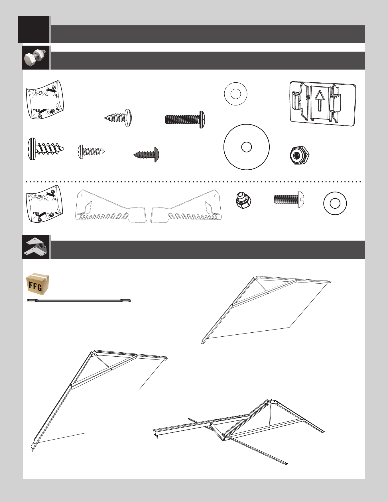
57
ROOF ASSEMBLY / ENSAMBLE DEL TEJADO / MONTAGE DU TOIT
9
AFL (x8)
ADZ (x170)
AED (x30)
ADX (x30)
AXX (x4)
FGA
Metal Parts / Piezas de metal / Pièces en métal
Hardware Bag / Bolsa de herraje / Sac de quincaillerie
PARTS REQUIRED / PIEZAS REQUERIDAS / PIÈCES REQUISES
HARDWARE REQUIRED / HERRAJE REQUERIDO / QUINCAILLERIE REQUISE
• No notches
• Sans encoches
• Sin muescas
• Notch
• Encoche
• Muesca
• No Notch
• Sans encoche
• Sin muesca
(x1)
(x2)
CWU (x24)
ECT
ECS (x1)
ADK (x2)
BZA (x2)
AEE (x4)
ECR (x1)
BHJ (x2)
DTV (x2)
CXK (x2)
AEE (x2)
(x1)
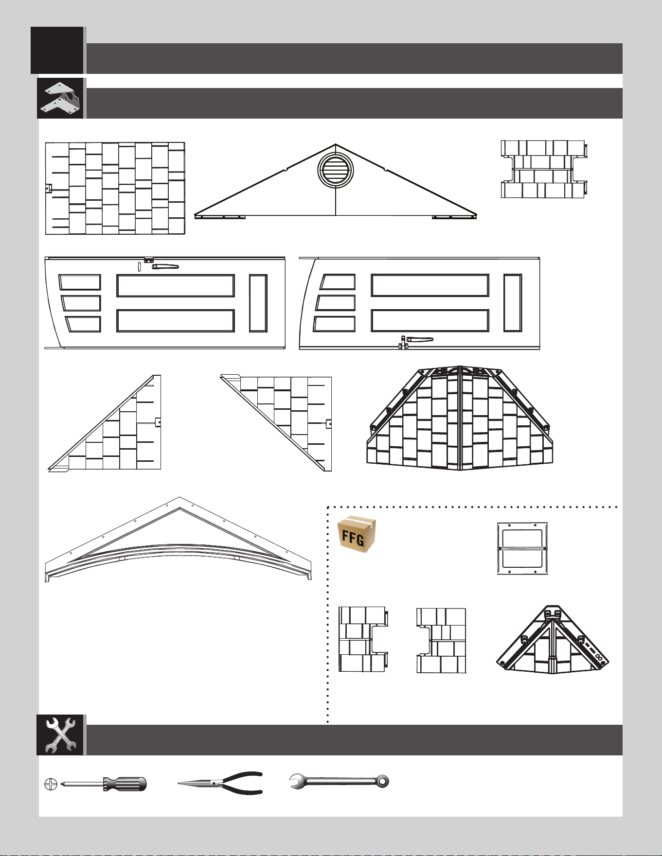
58
ROOF ASSEMBLY / ENSAMBLE DEL TEJADO / MONTAGE DU TOIT
9
PARTS REQUIRED / PIEZAS REQUERIDAS / PIÈCES REQUISES
(x2)
AGQ (x8)
AFY (117) (x4)
AHC (x5)
AGG (115) (x1)
AFW (116) (x1)
Plastic Parts / Piezas de plástico / Pièces en plastique
(x1)
(x1)
(x1)
BDS (x1)
DRA (x1)
DRB (x1)
BDR (x1)
TOOLS REQUIRED / INSTRUMENTAL REQUERIDO / OUTILS REQUIS
3/8 in/po
(10 mm)
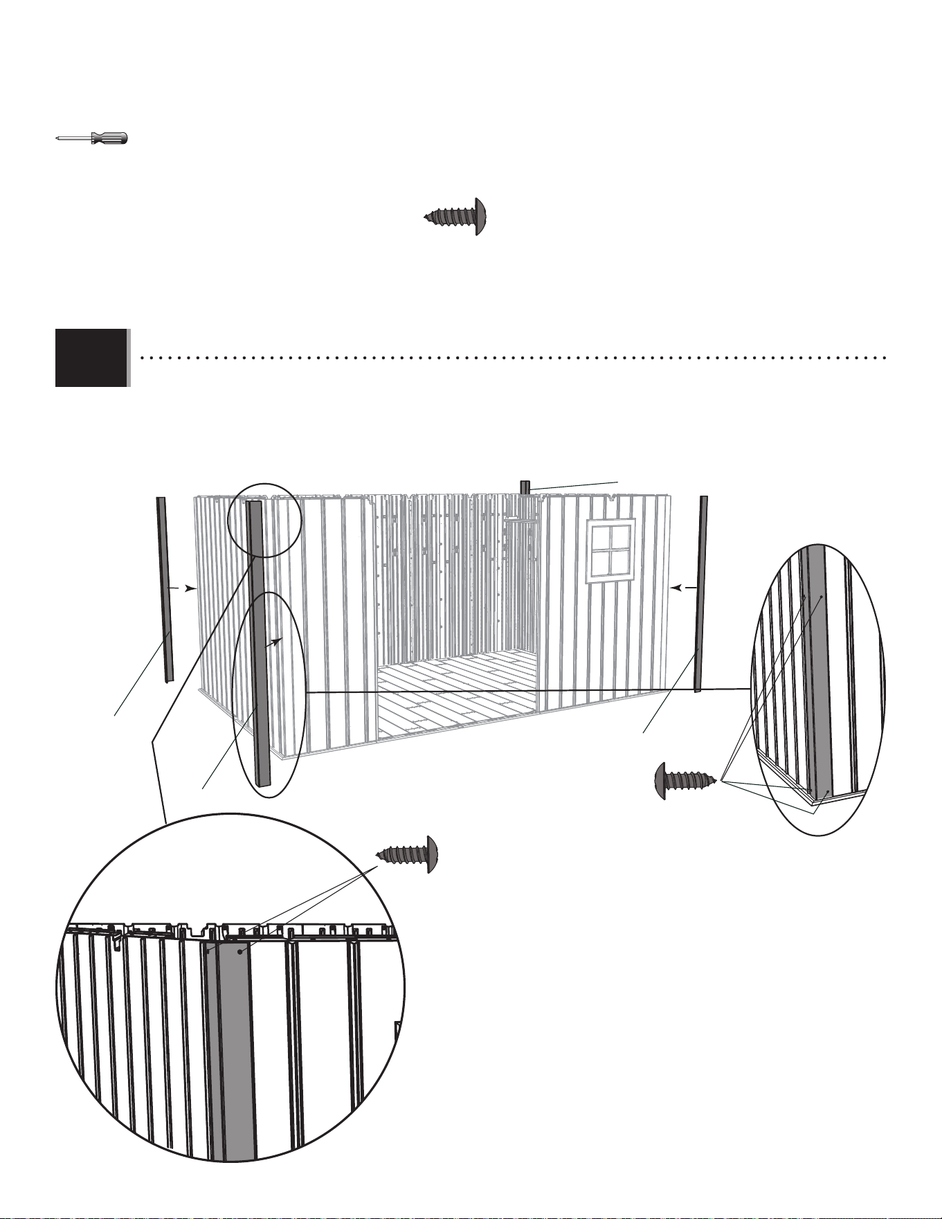
5959
X SECTION 9 (CONTINUED) / SECTION 9 (SUITE) / SECCIÓN 9 (CONTINUACIÓN)
TOOLS AND HARDWARE REQUIRED / OUTILS ET QUINCAILLERIE REQUIS / INSTRUMENTAL Y HERRAJE REQUERIDOS
• Attach a Corner Trim (CVG) to each corner with six (6) Screws (CWU)—two at the top, two in the middle, and two at
the bottom. The Trim should rest on the Floor. Repeat for the other corners.
• Attacher une moulure (CVG) à chaque coin à l’aide des six (6) vis (CWU) — deux à la partie supérieure, deux dans le
centre, et deux à la partie inférieure. Poser les pièces de moulure sur le plancher. Répéter pour les autres coins.
• Sujetar una moldura (CVG) a cada esquina usando seis (6) tornillos (CWU): dos a la parte superior, dos en el centro,
y dos a la parte inferior. Apoyar las piezas de moldura en el piso. Repetir para las otras esquinas.
9.1
CWU (x4)
CWU (x2)
CWU (x24)
CVG
CVG
CVG
CVG
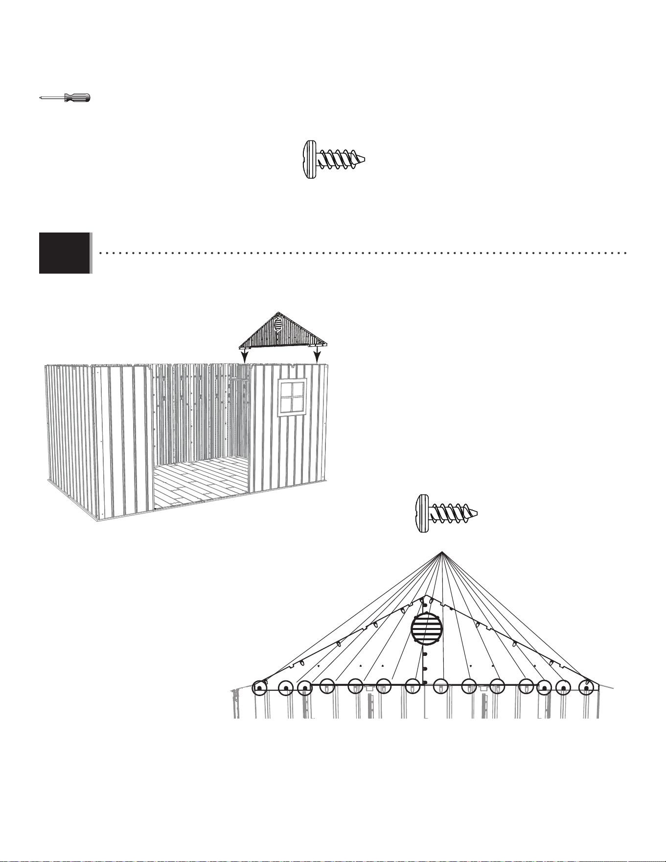
6060
X SECTION 9 (CONTINUED) / SECTION 9 (SUITE) / SECCIÓN 9 (CONTINUACIÓN)
TOOLS AND HARDWARE REQUIRED / OUTILS ET QUINCAILLERIE REQUIS / INSTRUMENTAL Y HERRAJE REQUERIDOS
9.2
ADZ (x14)
ADZ (x14)
• Attach a Side Gable to the shed using fourteen (14) Screws (ADZ).
• Attacher un pignon latéral à l’abri à l’aide de quatorze (14) vis (ADZ).
• Sujetar una fachada lateral a la caseta usando catorce (14) tornillos (ADZ).
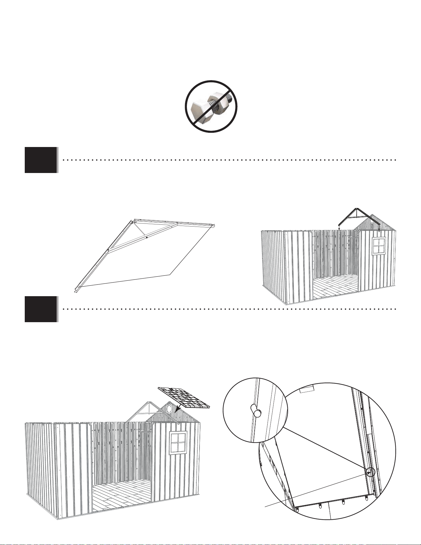
6161
X SECTION 9 (CONTINUED) / SECTION 9 (SUITE) / SECCIÓN 9 (CONTINUACIÓN)
TOOLS AND HARDWARE REQUIRED / OUTILS ET QUINCAILLERIE REQUIS / INSTRUMENTAL Y HERRAJE REQUERIDOS
9.3
9.4
• Place a Side Truss into the notches on the rear Wall Panel and Right, Front Window Wall Panel. While another
adult holds this in place, continue to the next step.
• Mettre une ferme latérale dans les encoches sur le panneau mural arrière et le panneau mural avant droit pour
la fenêtre. Pendant qu’un autre adulte soutient la ferme en place, continuer à la prochaine étape.
• Colocar una cercha lateral en las muescas en el panel mural trasero y el panel mural delantero derecho para la
ventana. Mientras que otro adulto mantenga la cercha en su lugar, seguir al próximo paso.
• No notches
• Sans encoches
• Sin muescas
AGQ
Alignment nub
Petite bosse d’alignement
Bulto de alineamiento
• Set the Roof Panel (AGQ) down onto the Wall Panel, Gable, and Truss. The groove at the bottom of the Roof Panel
sets over the top of the Wall Panel. Ensure the alignment nub fi ts into the notch in the Truss.
• Mettre le panneau de toit (AGQ) dans le panneau mural, le pignon, et la ferme. Mettez la rainure au bord inférieur
du panneau de toit sur la partie supérieure du panneau mural. Mettre la petite bosse d’alignement dans l’encoche
de la ferme.
• Colocar el panel de tejado (AGQ) en el panel de pared, la fachada, y la cercha. Colocar la ranura a lo largo del borde
inferior del panel de tejado sobre la parte superior del panel de pared. Encajar el bulto de alineamiento en la
muesca en la cercha.
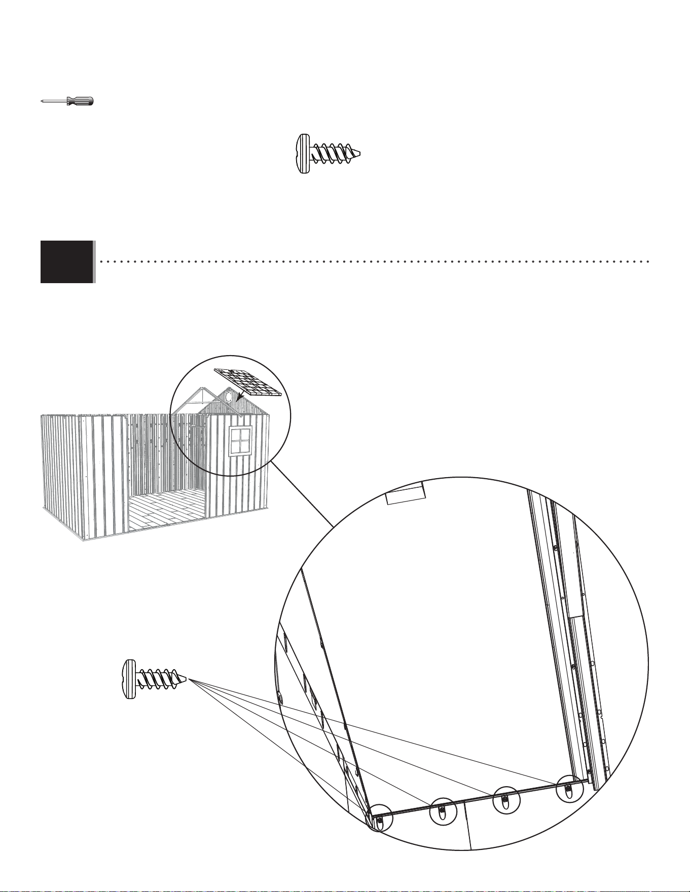
6262
X SECTION 9 (CONTINUED) / SECTION 9 (SUITE) / SECCIÓN 9 (CONTINUACIÓN)
TOOLS AND HARDWARE REQUIRED / OUTILS ET QUINCAILLERIE REQUIS / INSTRUMENTAL Y HERRAJE REQUERIDOS
ADZ (x4)
• Align the four holes in the Wall Panel with the slits at the bottom of the Roof Panel, and insert four (4) Screws (ADZ)
to secure the Panel in place.
• Aligner les quatre trous dans le panneau mural avec ceux au bord inférieur du panneau de toit, et insérer quatre
(4) vis (ADZ) pour l’attacher en place.
• Alinear los cuatro agujeros en el panel de pared con los al borde inferior del panel de tejado, e insertar cuatro (4)
tornillos (ADZ) para sujetarlo en su lugar.
ADZ (x4)
9.5
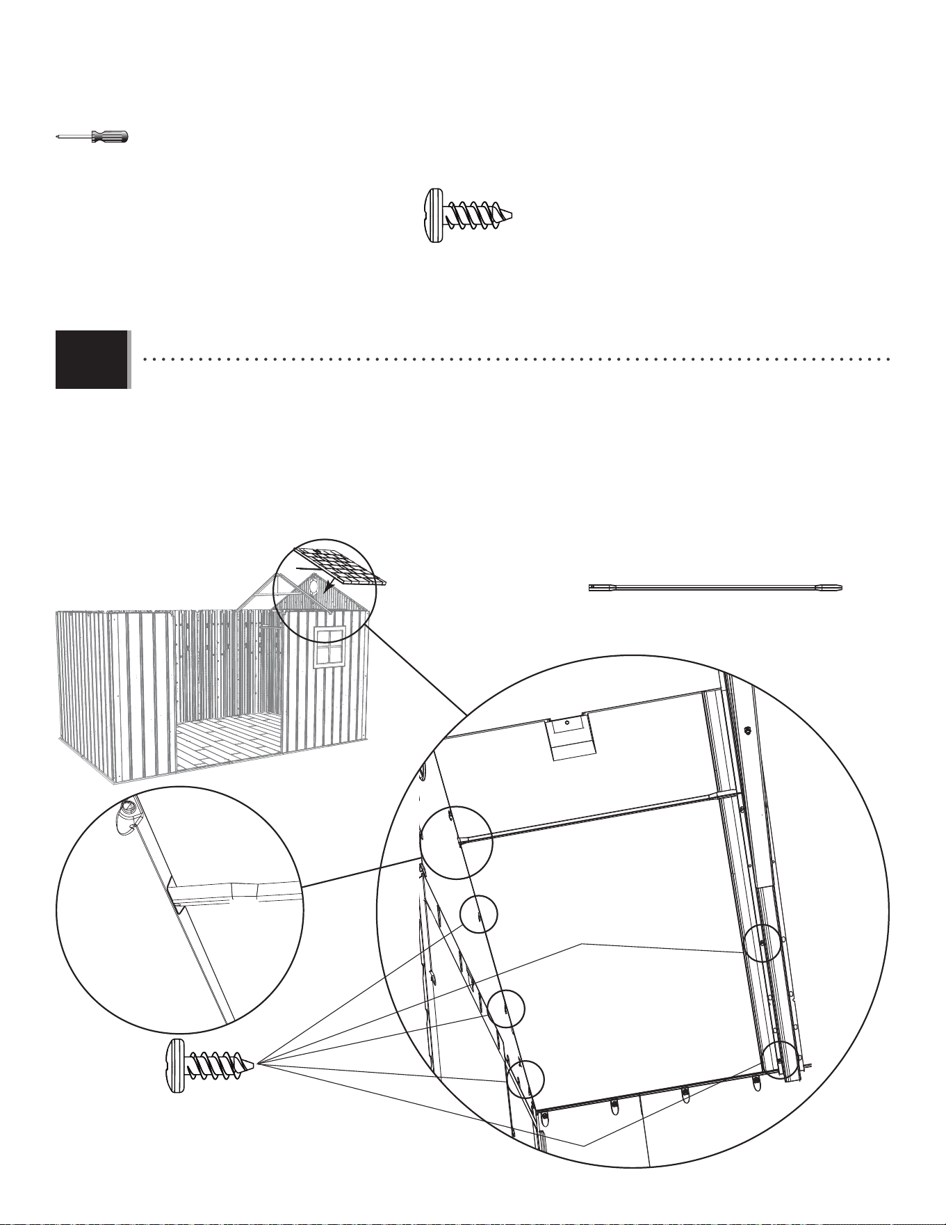
6363
X SECTION 9 (CONTINUED) / SECTION 9 (SUITE) / SECCIÓN 9 (CONTINUACIÓN)
TOOLS AND HARDWARE REQUIRED / OUTILS ET QUINCAILLERIE REQUIS / INSTRUMENTAL Y HERRAJE REQUERIDOS
ADZ (x5)
ADZ (x5)
AFL
AFL
• Insert the fi rst three Screws (ADZ) through the Gable and into the Roof Panel and the fi rst two Screws (ADZ) through
the Truss and into the Roof Panel at the locations shown. Then, insert the Roof Support (AFL) into the notches in the
Gable and between the Truss and the Roof Panel.
• Insérer les premières trois vis (ADZ) à travers le pignon et dans le panneau de toit avec lucarne et les premières
deux vis (ADZ) à travers la ferme et dans le panneau de toit aux emplacements indiqués. Ensuite, mettre le support
de toit (AFL) dans les encoches dans le pignon et entre le panneau de toit et la ferme.
• Insertar los primeros tres tornillos (ADZ) por la fachada y dentro del panel de tejado con tragaluz y los primeros
dos tornillos (ADZ) por la cercha y dentro del panel de tejado a las ubicaciones indicadas. Entonces, insertar el
soporte de tejado (AFL) en las muescas en la fachada y entre la cercha y el panel de tejado.
AFL (x1)
9.6
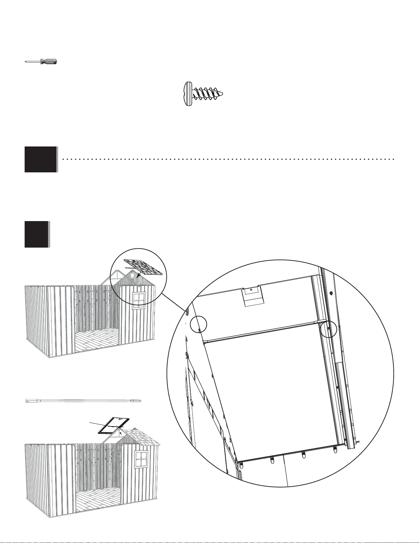
6464
X SECTION 9 (CONTINUED) / SECTION 9 (SUITE) / SECCIÓN 9 (CONTINUACIÓN)
TOOLS AND HARDWARE REQUIRED / OUTILS ET QUINCAILLERIE REQUIS / INSTRUMENTAL Y HERRAJE REQUERIDOS
ADZ (x13)
AFL (1)
AGQ
• Insert one Screw (ADZ) through the Gable and into the Roof Panel and one Screw (ADZ) through the Truss and into
the Roof Panel at the locations shown.
• Insérer une vis (ADZ) à travers le pignon et dans le panneau de toit et une vis (ADZ) à travers la ferme et dans le
panneau de toit aux endroits illustrés.
• Insertar un tornillo (ADZ) por la fachada y dentro del panel de tejado y un tornillo (ADZ) por la cercha y dentro del
panel de tejado a las ubicaciones indicadas.
Note: Repeat the previous steps for the rear Roof Panel (AGQ).
Remarque : Répéter les étapes précédentes pour le panneau de toit (AGQ) arrière.
Nota : Repetir los pasos anteriores para el panel de tejado (AGQ) trasero.
!
AFL (x1)
AFL
9.7
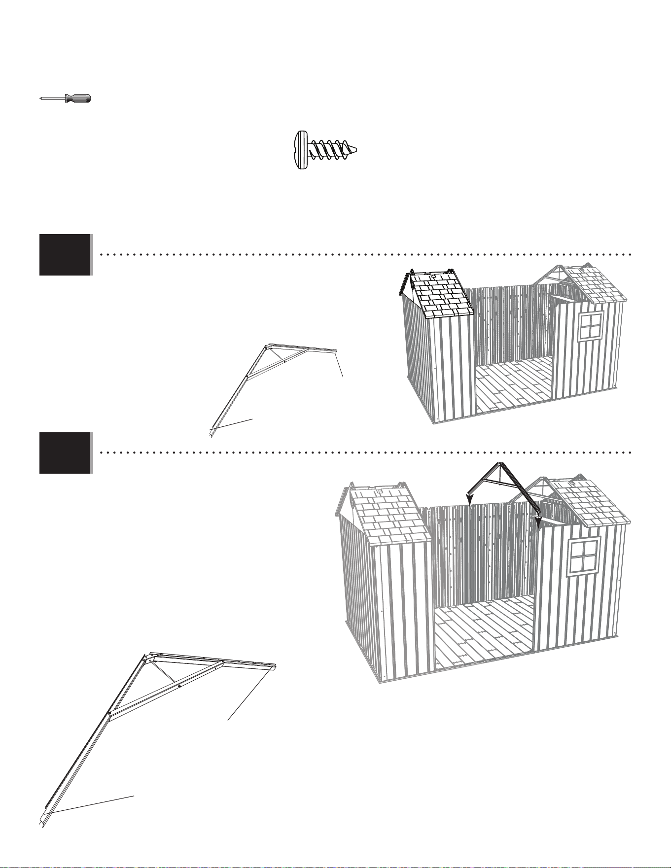
6565
X SECTION 9 (CONTINUED) / SECTION 9 (SUITE) / SECCIÓN 9 (CONTINUACIÓN)
TOOLS AND HARDWARE REQUIRED / OUTILS ET QUINCAILLERIE REQUIS / INSTRUMENTAL Y HERRAJE REQUERIDOS
• Repeat steps 9.2–9.7 for the left side of the shed. Remember to use the
Truss with notches. The end with the notch goes at the front.
• Répéter les étapes 9.2 – 9.7 pour le côté gauche de l’abri. Veiller utiliser
la ferme avec encoches. L’extrémité avec l’encoche va vers l’avant.
• Repetir los pasos 9.2–9.7 para el lado izquierdo de la caseta. Es
necesario usar la cercha que tiene muescas. El extremo con la muesca va
hacia la parte delantera.
• Set the Notched Truss into the notches on
opposite Wall Panels. The end with the notch goes at
the front. While another adult holds this in place,
continue to the next step.
• Mettre la ferme avec l’encoche dans les
encoches des panneaux muraux opposés.
L’extrémité avec l’encoche va vers l’avant. Pendant
qu’un autre adulte soutient la ferme en place,
continuer à la prochaine étape.
• Colocar la cercha con la muesca en las muescas
de los paneles murales opuestos. El extremo con la
muesca va hacia la parte delantera. Mientras que otro
adulto mantenga la cercha en su lugar, seguir al
próximo paso.
• Notch
• Encoche
• Muesca
• Notch
• Encoche
• Muesca
• No Notch
• Sans encoche
• Sin muesca
• No Notch
• Sans encoche
• Sin muesca
9.8
9.9
ADZ (x22)
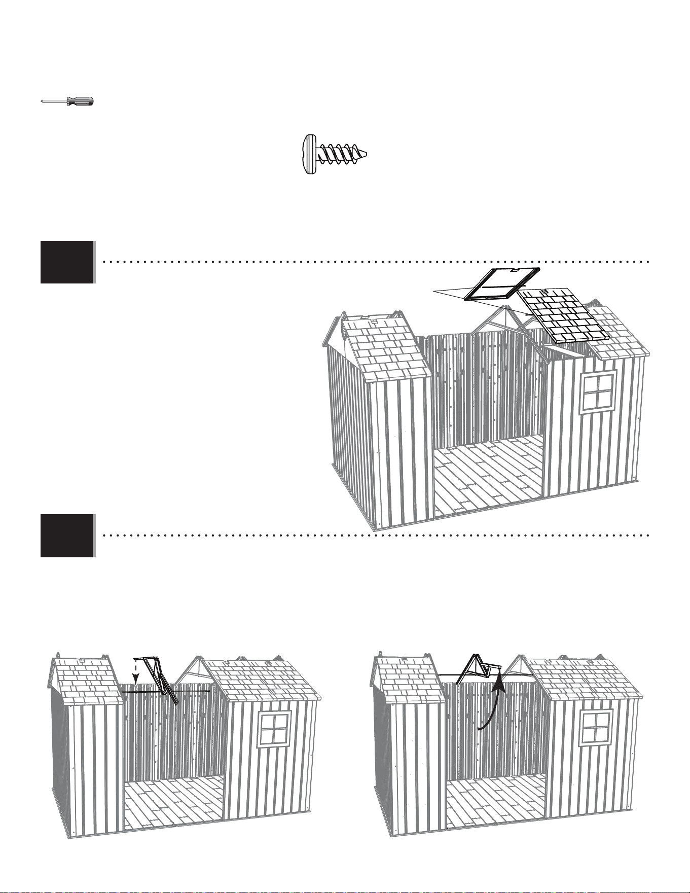
6666
X SECTION 9 (CONTINUED) / SECTION 9 (SUITE) / SECCIÓN 9 (CONTINUACIÓN)
TOOLS AND HARDWARE REQUIRED / OUTILS ET QUINCAILLERIE REQUIS / INSTRUMENTAL Y HERRAJE REQUERIDOS
• While an adult holds the Truss in place,
attach a Roof Panel (AGQ) to the front and rear
of the shed. Remember to insert the Roof Supports
(AFL) as you attach the panels.
• Pendant qu’un adulte maintient la ferme
en place, attacher un panneau de toit (AGQ) aux
parties avant et derrière de l’abri. Veiller insérer
les supports de toit (AFL) alors que vous attachez les
panneaux.
• Mientras que un adulto mantenga la cercha
en su lugar, sujetar un panel de tejado (AGQ) a
las partes delantera y trasera de la caseta. Es
importante insertar los soportes de tejado (AFL) al
sujetar los paneles.
9.10
9.11
ADZ (x20)
ADZ
ADZ
AFL
• Place the back of the Center Truss into the notch on the rear Wall Panel. Then, lift the front of the Truss up so
the ends of the Roof Support Tube touch the Side Trusses.
• Mettre l’extrémité arrière de la ferme dans l’encoche sur le panneau mural arrière central. Ensuite, soulever
l’extrémité avant de la ferme pour que les extrémités du tube de support touchent les fermes latéraux.
• Colocar el extremo trasero de la cercha en la muesca en el panel de tejado central trasero. Entonces, levantar
el extremo delantero de la cercha para arriba para que los extremos del tubo de soporte hagan contacto con las
cerchas laterales.
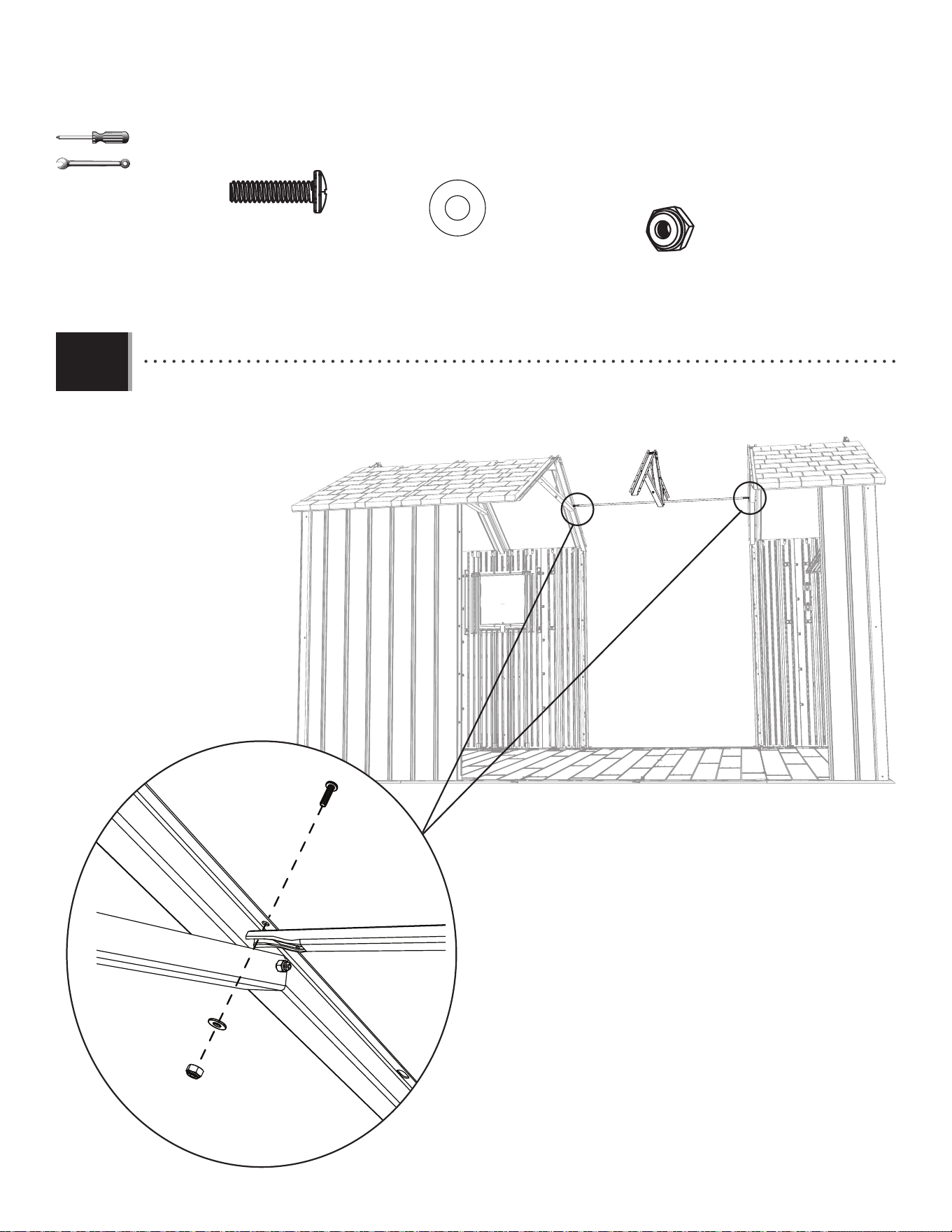
6767
X SECTION 9 (CONTINUED) / SECTION 9 (SUITE) / SECCIÓN 9 (CONTINUACIÓN)
TOOLS AND HARDWARE REQUIRED / OUTILS ET QUINCAILLERIE REQUIS / INSTRUMENTAL Y HERRAJE REQUERIDOS
3/8 in/po
(10 mm)
DTV (x2)
CXK (x2)
AEE (x2)
• Secure the ends of the Support Tube to the underside of the Truss Channels using the hardware provided.
• Attacher bien les extrémités du tube de support au dessous des fermes à l’aide de la quincaillerie incluse.
• Sujetar los extremos del tubo de soporte a la superfi cie inferior de las cerchas usando el herraje incluido.
DTV
AEE
CXK
9.12
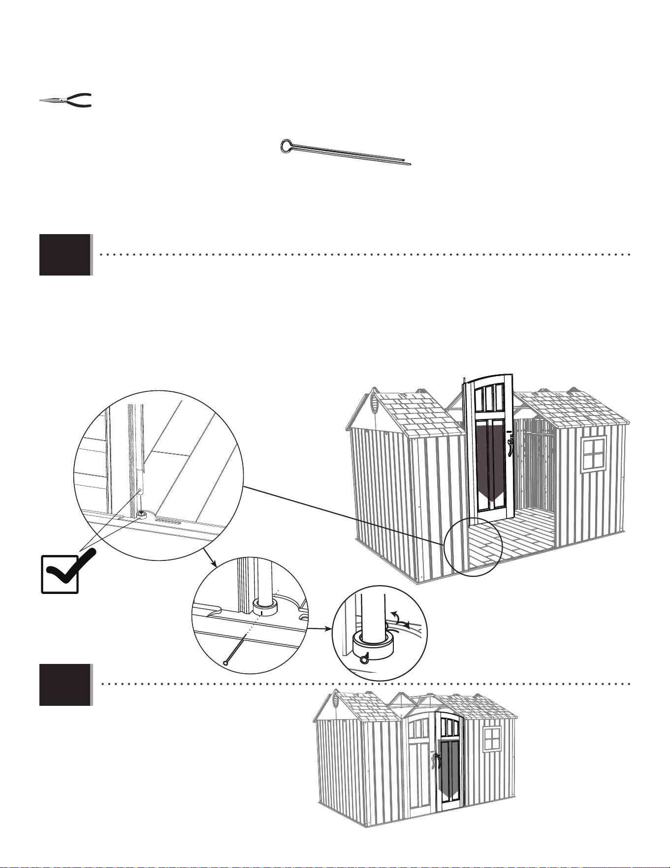
6868
X SECTION 9 (CONTINUED) / SECTION 9 (SUITE) / SECCIÓN 9 (CONTINUACIÓN)
TOOLS AND HARDWARE REQUIRED / OUTILS ET QUINCAILLERIE REQUIS / INSTRUMENTAL Y HERRAJE REQUERIDOS
AHP (x2)
AHP
• Pull the Hinge Tube down out of the Left Door about six inches. Align the hole at the bottom of the Hinge Tube
with the slit in the Bushing, and insert the Tube. Insert a Cotter Pin (AHP) and bend the ends.
• Étendre le tube d’articulation à peu près quinze centimètres du bord inférieur de la porte. Aligner le trou dans
la partie inférieure du tube avec la fente dans la bague, et insérer le tube. Insérer une clavette (AHP), et plier les
extrémités.
• Extender el tubo de articulación unos qunice centimetros del borde inferior de la puerta. Alinear el agujero en
la parte inferior del tubo con la rendija en el casquillo, e insertar el tubo. Insertar una clavija (AHP), y doblar los
extremos.
• Repeat this step for the Right Door.
• Répéter cette étape pour la porte droite.
• Repetir este paso para la puerta derecha.
9.13
9.14
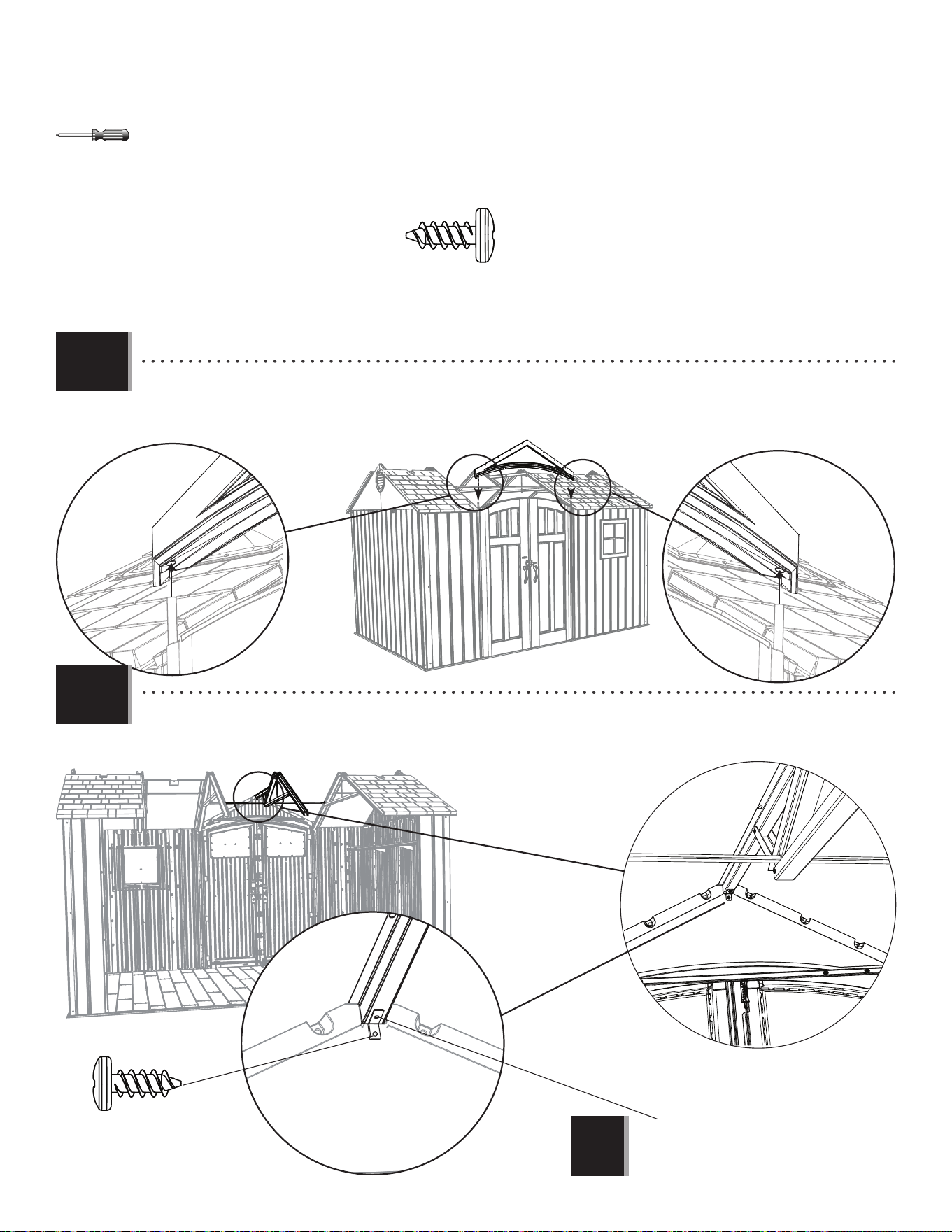
6969
X SECTION 9 (CONTINUED) / SECTION 9 (SUITE) / SECCIÓN 9 (CONTINUACIÓN)
TOOLS AND HARDWARE REQUIRED / OUTILS ET QUINCAILLERIE REQUIS / INSTRUMENTAL Y HERRAJE REQUERIDOS
ADZ (x1)
• Set the end of the Center Truss onto the notch in the Front Gable Panel as shown.
• Colocar el extremo de la cercha central en la muesca en la fachada delantera como se muestra.
• Mettre l’extrémité de la ferme centrale dans l’encoche dans la pignon avant comme illustré.
• Slide the holes in the Entry Gable down over the two Hinge Tubes.
• Faire glisser les trous dans le pignon d’entrée sur les deux tubes.
• Deslizar los agujeros en la fachada de entrada sobre los dos tubos.
Note: Tighten this Nut and Bolt now.
Remarque : Serrer cette vis et l’écrou maintenant.
Nota: Apretar este perno y la tuerca ahora.
!
ADZ
9.15
9.16
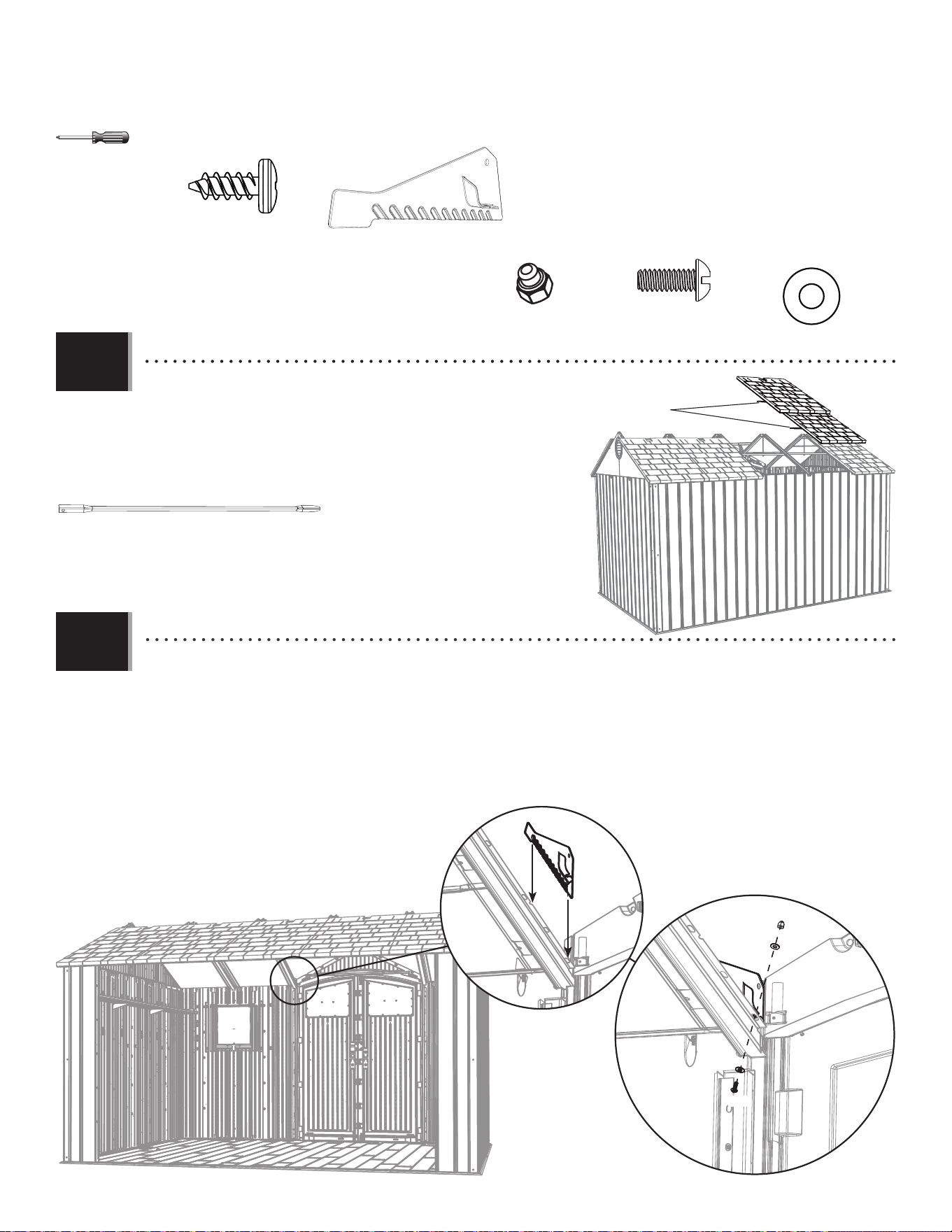
7070
X SECTION 9 (CONTINUED) / SECTION 9 (SUITE) / SECCIÓN 9 (CONTINUACIÓN)
TOOLS AND HARDWARE REQUIRED / OUTILS ET QUINCAILLERIE REQUIS / INSTRUMENTAL Y HERRAJE REQUERIDOS
ADZ (x20)
AGQ
AGQ
• Attach the two center, rear Roof Panels using only one Roof
Support per Panel.
• Attacher les deux panneaux de toit arrières centraux en utilisant
un seul support de toit pour chaque panneau.
• Sujetar los dos paneles de tejado traseros centrales usando sólo
un soporte de tejado por panel.
AFL (x2)
AFL
• Insert the Right Drainage Plate (ECS) into the Right Lateral Truss, and align the notch in the Plate with the fi rst hole
in the Truss as shown. Secure with the hardware provided. Only tighten by hand for now.
• Insérer la plaque de drainage droite (ECS) dans la ferme latérale droite, et aligner l’encoche dans la plaque avec la
premier trous dans la ferme comme illustré. Attacher-la bien à la ferme à l’aide de la quincaillerie incluse. Ne serrer
qu’à la main en ce moment.
• Insertar la placa derecha para el drenaje (ECS) dentro de la cercha lateral derecho, y alinear la muesca en la placa
con el primer agujero en la cercha. Sujetarla a la cercha usando el herraje incluido. Apretar sólo a mano en este
momento.
ECS (x1)
ADK
AEE
AEE
ADK (x1)
BZA (x1)
AEE (x2)
BZA
ECS
9.17
9.18
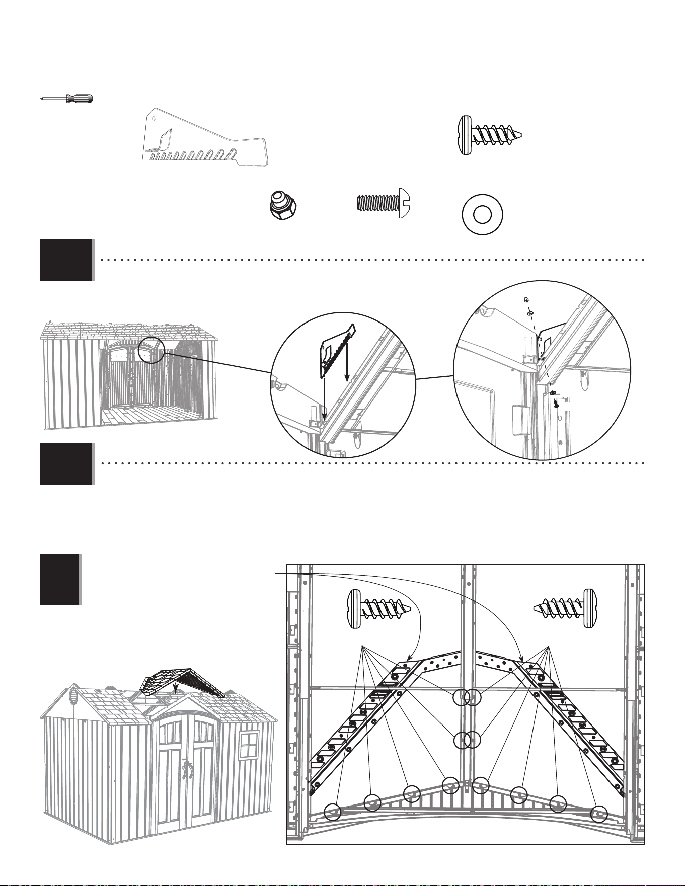
7171
X SECTION 9 (CONTINUED) / SECTION 9 (SUITE) / SECCIÓN 9 (CONTINUACIÓN)
TOOLS AND HARDWARE REQUIRED / OUTILS ET QUINCAILLERIE REQUIS / INSTRUMENTAL Y HERRAJE REQUERIDOS
ADZ (x6)ADZ (x6)
• Fold the ends of the Large Angled Roof Panel (DRA) and set it down onto the shed as shown. Secure the Panel to the
Entry Gable and Center Truss with twelve (12) Screws (ADZ) at the locations shown.
• Plier les extrémités du panneau de toit angulaire grand (DRA) et mettre-le sur l’abri comme illustré. Attacher-le bien au
pignon et à la ferme centrale à l’aide de douze (12) vis (ADZ) aux emplacements indiqués.
• Doblar los extremos del panel de tejado angular grande (DRA) y colocarlo en la caseta como se muestra. Sujetarlo a la
fachada y la cercha central usando doce (12) tornillos (ADZ) a las ubicaciones indicadas.
Note: Fold these ends upward before installing.
Remarque : Plier ces rabats en haut avant d’installer.
Nota: Doblar estas solapas hacia arriba antes de
instalar.
!
ADZ (x12)
• Repeat the last step for the Left Drainage Plate (ECR).
• Répéter l’étape précédente pour la plaque gauche de drainage (ECR).
• Repetir el paso anterior para la placa izquierda para el drenaje (ECR).
ECR (x1)
ADK (x1)
BZA (x1)
AEE (x2)
ECR
ADK
AEE
AEE
BZA
DRA
9.19
9.20
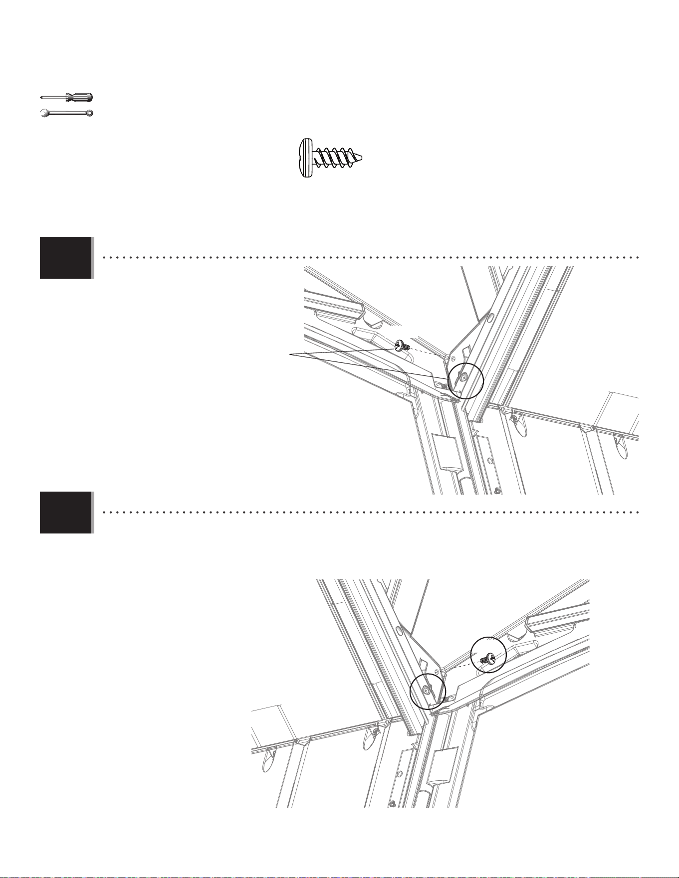
7272
X SECTION 9 (CONTINUED) / SECTION 9 (SUITE) / SECCIÓN 9 (CONTINUACIÓN)
TOOLS AND HARDWARE REQUIRED / OUTILS ET QUINCAILLERIE REQUIS / INSTRUMENTAL Y HERRAJE REQUERIDOS
• Secure the Drainiage Plate from step
9.16 to the Roof at the location shown.
Tighten the Nut on the Drainage Plate now.
• Attacher la plaque de drainage des
étapes 9.16 au toit à l’emplacement
indiqué. Serrer l’écrou dans la plaque de
drainage.
• Sujetar la placa de drenaje de los
pasos 9.16 al tejado a la ubicación
indicada. Apretar la tuerca en la placa de
drenaje ahora.
ADZ
ADZ
• Repeat the last step for the right Drainage Plate.
• Répéter l’étape précédente pour la plaque de drainage droite.
• Repetir el paso anterior para la placa de drenaje derecha.
3/8 in/po
(10 mm)
ADZ (x2)
9.21
9.22
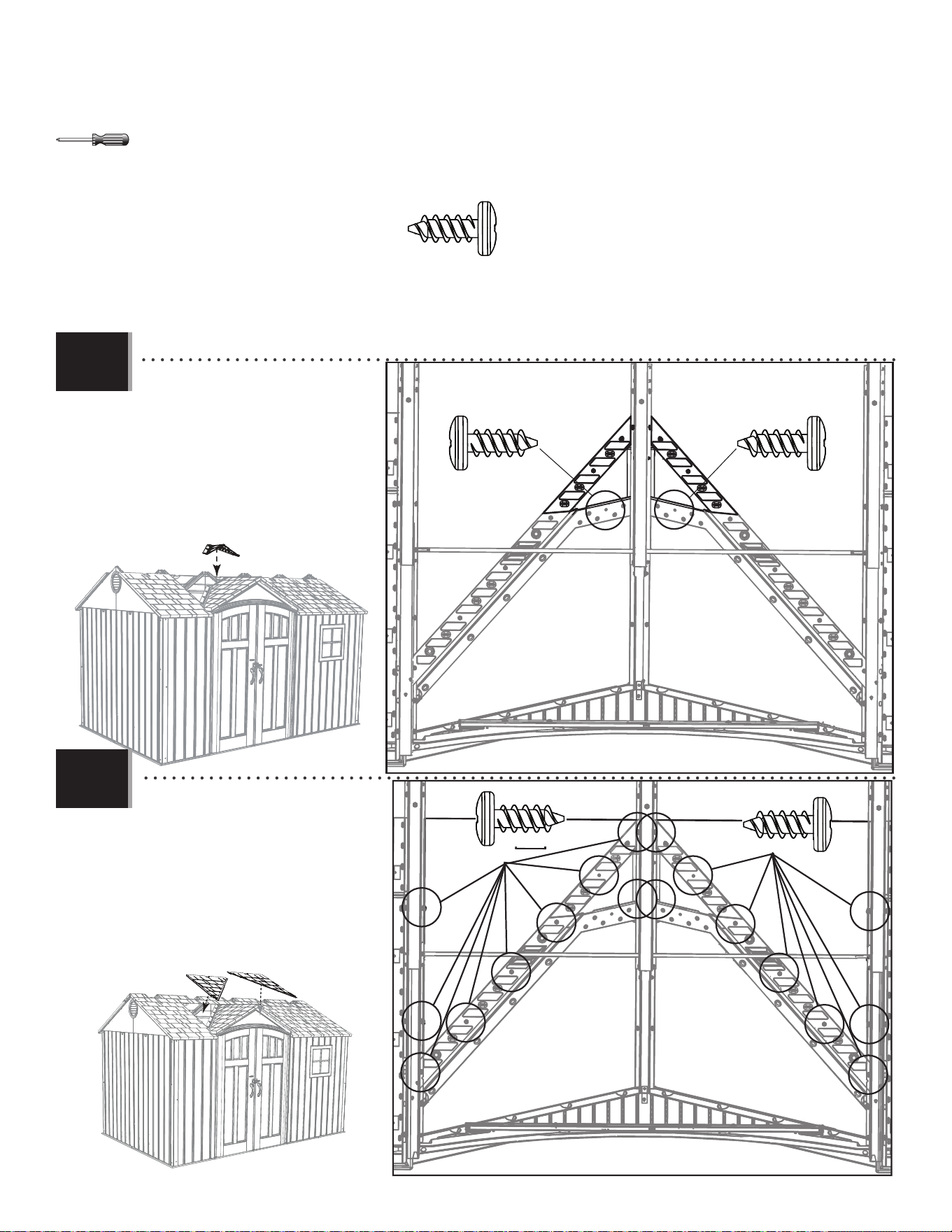
7373
X SECTION 9 (CONTINUED) / SECTION 9 (SUITE) / SECCIÓN 9 (CONTINUACIÓN)
TOOLS AND HARDWARE REQUIRED / OUTILS ET QUINCAILLERIE REQUIS / INSTRUMENTAL Y HERRAJE REQUERIDOS
• An adult must apply a downward
pressure on Panel (DRB) while another
inserts these Screws (ADZ).
• Une adulte doit appliquer pression
sur le panneau (DRB) pendant
l’insertion de ces vis (ADZ).
• Un adulto debe aplicar una presión
de arriba en el panel (DRB) durante la
inserción de estos tornillos (ADZ).
ADZ (x20)
ADZ (x1)
ADZ (x1)
ADZ (x9)
ADZ (x9)
• An adult must apply a downward
pressure on Panels (BDS & BDR) while
another inserts these Screws (ADZ).
• Une adulte doit appliquer pression
sur les panneaux (BDS et BDR) pendant
l’insertion de ces vis (ADZ).
• Un adulto debe aplicar una presión
de arriba en los paneles (BDS y BDR)
durante la inserción de estos tornillos
(ADZ).
BDR
BDS
DRB
9.23
9.24
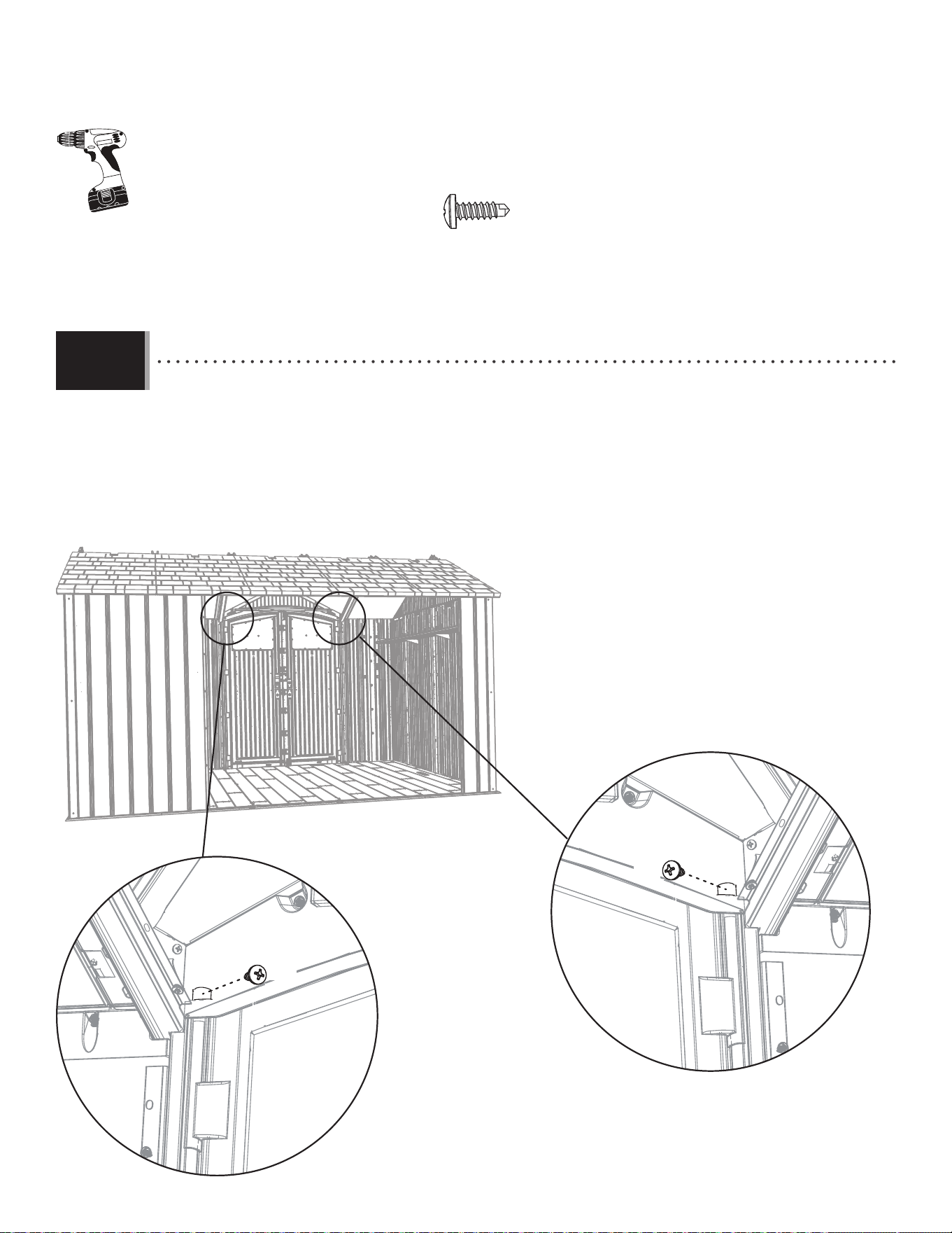
7474
X SECTION 9 (CONTINUED) / SECTION 9 (SUITE) / SECCIÓN 9 (CONTINUACIÓN)
TOOLS AND HARDWARE REQUIRED / OUTILS ET QUINCAILLERIE REQUIS / INSTRUMENTAL Y HERRAJE REQUERIDOS
BHJ (x2)
BHJ
• Use an electric screwdriver to Insert a Self Tapping Screw (BHJ) through the plastic of the Gable and into the Right
and Left Door Hinge Tubes at the location shown.
• Employez un perceuse électrique pour insérer une vis autotaraudeuse (BHJ) à travers le pignon et dans les
charnières des portes aux emplacements indiqués.
• Utilice un taladro eléctrico para introducir un tornillo auto-roscante (BHJ) a través la fachada y dentro de las
bisagras derecha e izquierda a las ubicaciones indicadas.
9.25
BHJ
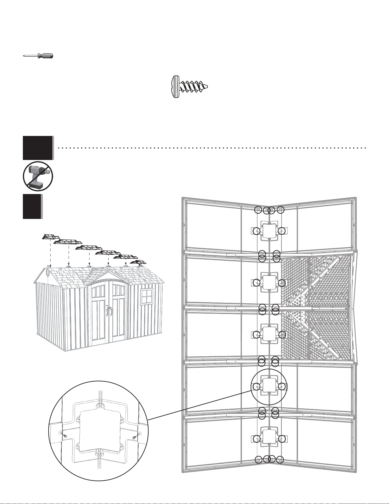
7575
X SECTION 9 (CONTINUED) / SECTION 9 (SUITE) / SECCIÓN 9 (CONTINUACIÓN)
TOOLS AND HARDWARE REQUIRED / OUTILS ET QUINCAILLERIE REQUIS / INSTRUMENTAL Y HERRAJE REQUERIDOS
ADZ (x34)
AFW
AGG
AFY
AFY
AFY
AFY
ADZ
ADZ
• Starting at the front, attach the Roof Caps to the shed using the hardware included.
• En commençant à la partie avant, attacher les chapeaux à l’abri à l’aide de la quincaillerie incluse.
• Empezando a la parte delantera, sujetar las cumbreras a la caseta usando el herraje incluido.
Note: The ends of the Roof Caps overlap one another.
Remarque : Los extremos de las cumbreras se solapan.
Note : Les extrémités des chapeaux se chevauchent.
!
9.26
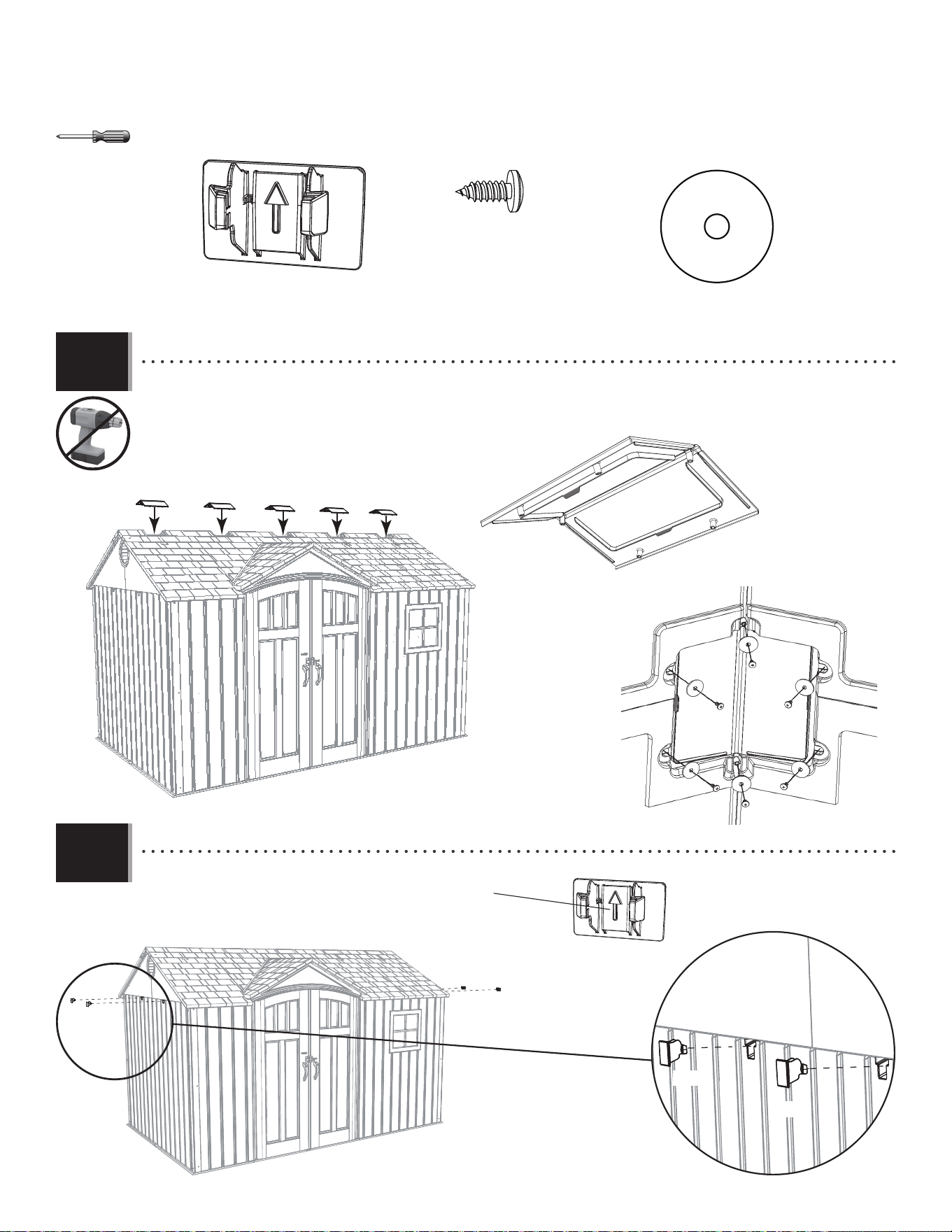
7676
X SECTION 9 (CONTINUED) / SECTION 9 (SUITE) / SECCIÓN 9 (CONTINUACIÓN)
TOOLS AND HARDWARE REQUIRED / OUTILS ET QUINCAILLERIE REQUIS / INSTRUMENTAL Y HERRAJE REQUERIDOS
AHC
ADX (x30)
AED (x30)
AXX (x4)
ADX
AED
AHC
AHC
AHC
AHC
AHC
AXX
AXX
• Insert the Clips (AXX) with the “arrow” facing up.
• Insérer les clips (AXX) avec la « fl èche » vers le haut.
• Insertar los clips (AXX) con la «fl echa» hacia arriba.
• Fold the Skylights (AHC), and attach them to the Roof using six (6) Screws (ADX) and Washers (AED) for each Skylight.
• Plier les lucarnes (AHC), et attacher-les au toit à l’aide de six (6) vis (ADX) et rondelles (AED) pour chaque lucarne.
• Doblar los tragaluces (AHC), y sujetarlos al tejado usando seis (6) tornillos (ADX) y rondanas (AED) para cada tragaluz.
9.27
9.28
AXX
AXX
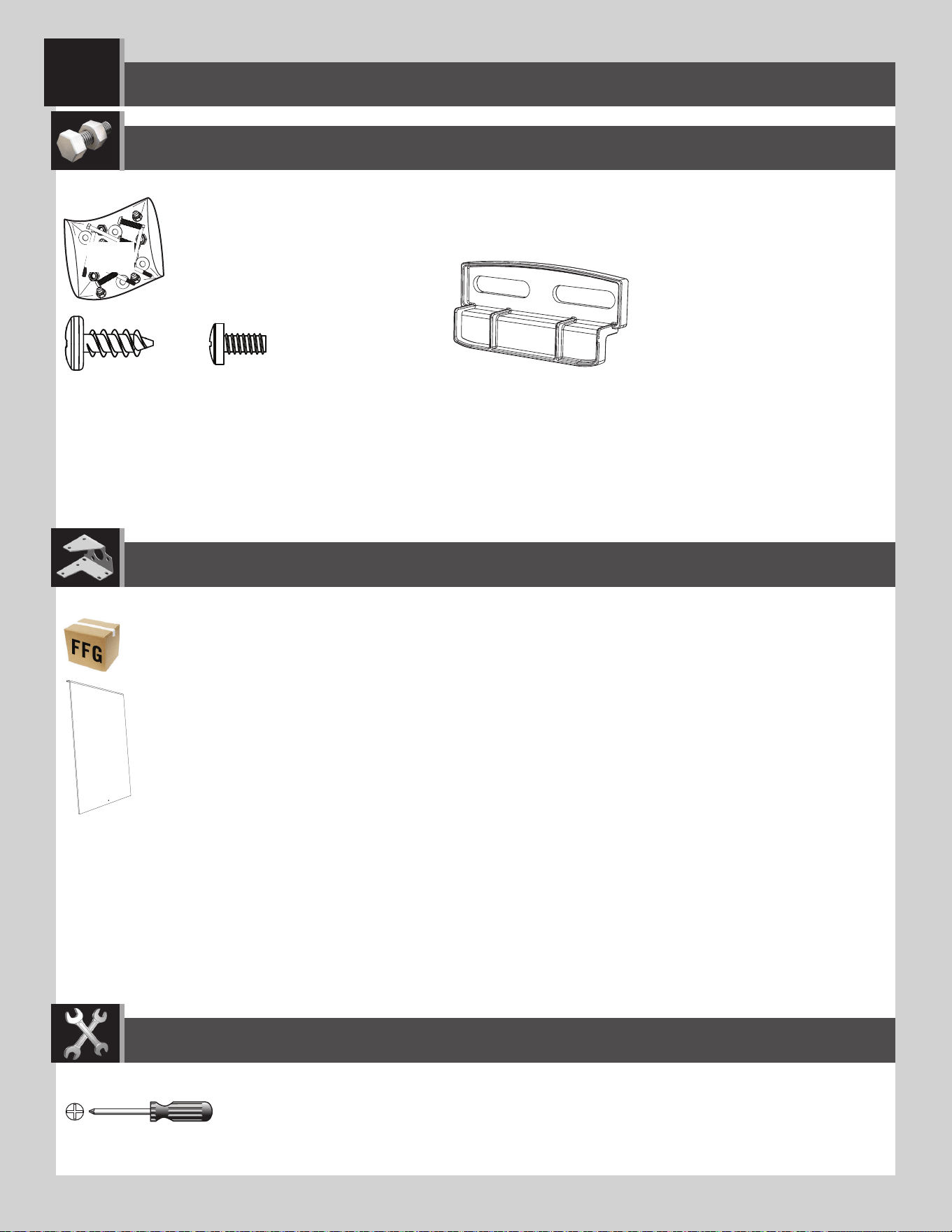
77
WINDOW PANE INSTALLATION / INSTALACIÓN DE LAS HOJAS DE VENTANA / INSTALLATION DES CARREAUX
10
ADZ (x4)
ADY (x1)
AIS (x2)
AHE (x1)
BEJ
Plastic Parts / Piezas de plástico / Pièces en plastique
Hardware Bag / Bolsa de herraje / Sac de quincaillerie
TOOLS REQUIRED / INSTRUMENTAL REQUERIDO / OUTILS REQUIS
PARTS REQUIRED / PIEZAS REQUERIDAS / PIÈCES REQUISES
HARDWARE REQUIRED / HERRAJE REQUERIDO / QUINCAILLERIE REQUISE
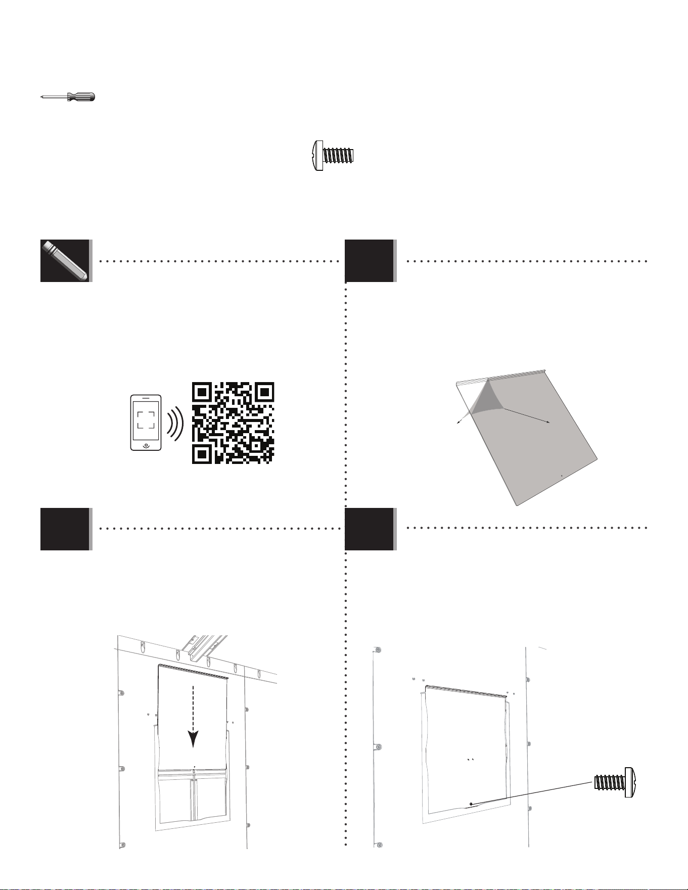
78
TOOLS AND HARDWARE REQUIRED / INSTRUMENTAL Y HERRAJE REQUERIDOS / OUTILS ET QUINCAILLERIE REQUIS
X SECTION 10 (CONTINUED) / SECCIÓN 10 (CONTINUACIÓN) / SECTION 10 (SUITE)
ADY (x2)
AHE
ADY
AHE
• Peel off the protective backing from both sides
of the Window Pane (AHE).
• Retirer la pellicule protectrice des deux côtés du
carreau (AHE).
• Retirar el protector de plástico de las dos caras
de la hoja de ventana (AHE).
• Insert a Screw (ADY) into the hole at the bottom of the
Window Pane. This helps keep the Window up when open.
• Insérer une vis (ADY) dans le trou au bord inférieur
du carreau. Cela aide à maintenir le carreau vers le haut
lorsqu’il est ouvert.
• Insertar un tornillo (ADY) en el agujero al borde
inferior de la hoja. Esto ayuda a prevenir la cierre de la
hoja de ventana.
10.2
10.1
10.3
• If you have trouble with these steps, follow the code below
to view a video on the installation in this section.
• En cas de problèmes avec ces étapes, suivre le code en
bas pour voir un vidéo sur l’installation de cette section.
• En caso de algún problema con estos pasos, seguir el
código debajo para ver un video sobre la instalación en esta
sección.
http://go.lifetime.com/8wininstall
• With the curved edge at the top and facing
toward you, slide the Window Pane down into the
opening.
• Avec le bord courbé vers le haut et faisant face
de vous, faire glisser le carreau en place.
• Con el borde curvado hacia arriba y el interior,
deslizar la hoja de ventana en su lugar.
LIFETIME
©
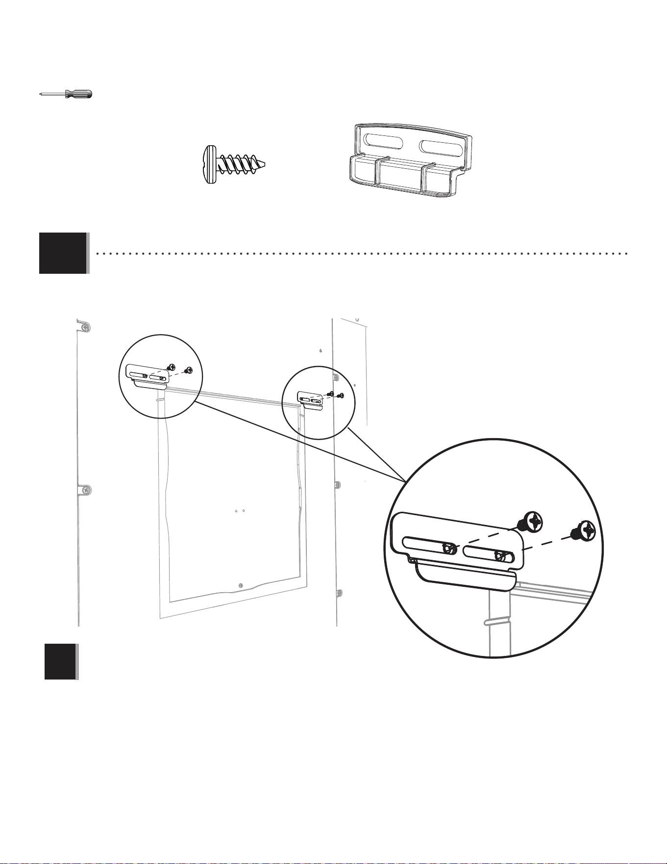
79
TOOLS AND HARDWARE REQUIRED / INSTRUMENTAL Y HERRAJE REQUERIDOS / OUTILS ET QUINCAILLERIE REQUIS
X SECTION 10 (CONTINUED) / SECCIÓN 10 (CONTINUACIÓN) / SECTION 10 (SUITE)
AIS
ADZ
ADZ
• Attach the two (2) Window Latches (ADY) at the top corners of the Panel opening.
• Attacher les deux (2) loquets (ADY) aux angles supérieurs de l’ouverture du panneau.
• Sujetar los dos (2) cerrojos (ADY) a las esquinas superiores de la abertura del panel.
Note: The Latch should move freely.
Remarque : Le loquet doit se déplacer librement.
Nota: El cerrojo debe mover libremente.
!
10.4
ADZ (x8)
AIS (x4)
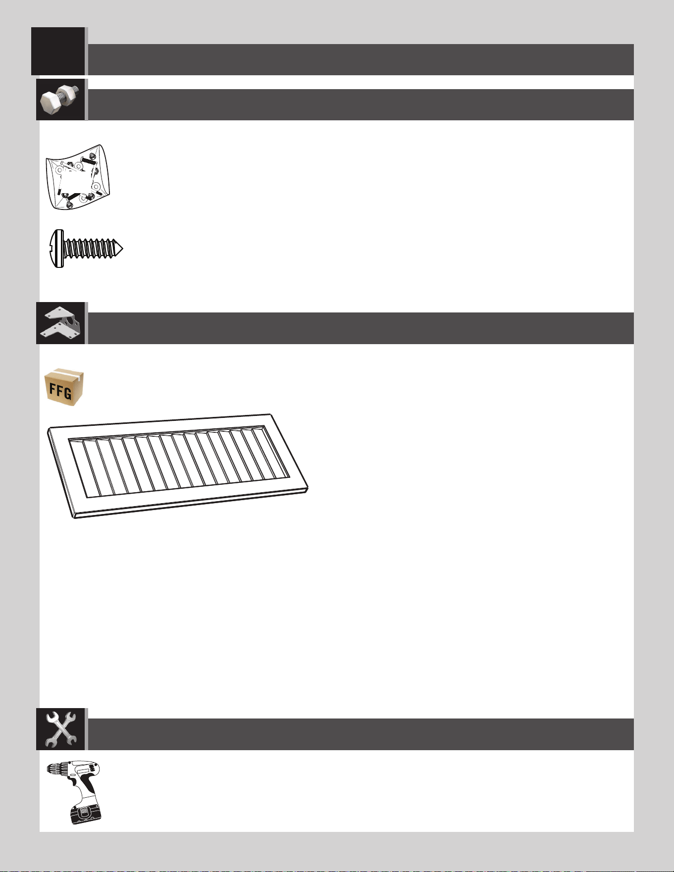
80
SHUTTER INSTALLATION / INSTALLATION DES VOLETS / INSTALACIÓN DE LAS CONTRAVENTANAS
11
ARV (x8)
AYI (x2)
BJI
Plastic Part / Pièce en plastique / Pieza de plástico
Hardware Bag / Sac de quincaillerie / Bolsa de herraje
PARTS REQUIRED / PIÈCES REQUISES / PIEZAS REQUERIDAS
HARDWARE REQUIRED / QUINCAILLERIE REQUISE / HERRAJE REQUERIDO
TOOLS REQUIRED / OUTILS REQUIS / INSTRUMENTAL REQUERIDO
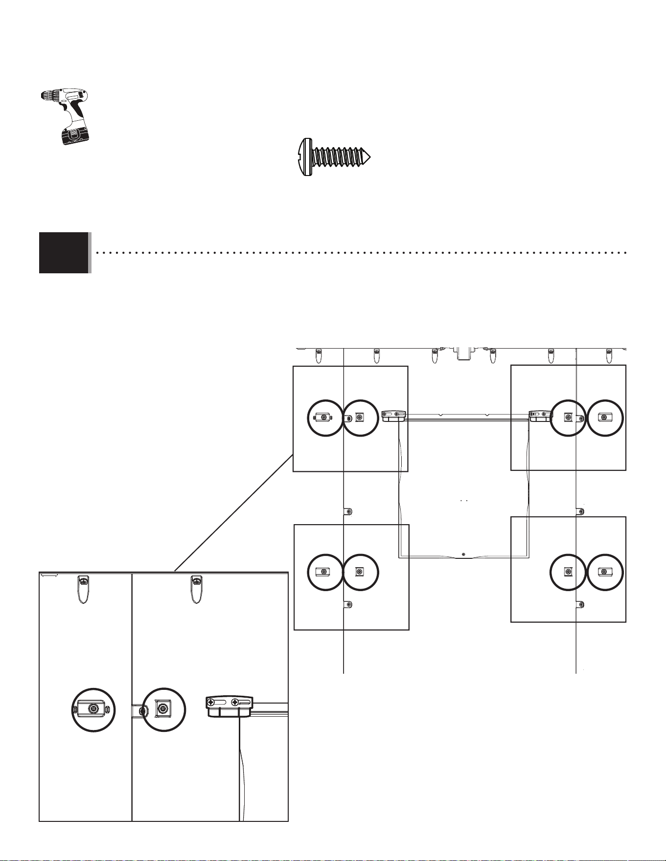
81
TOOLS AND HARDWARE REQUIRED / OUTILS ET QUINCAILLERIE REQUIS / INSTRUMENTAL Y HERRAJE REQUERIDOS
X SECTION 11 (CONTINUED) / SECTION 11 (SUITE) / SECCIÓN 11 (CONTINUACIÓN)
11.1
ARV (x1)
• There are four sets of two screw-location indicators. One by one, insert the Screws (ARV) through the indicators from the
inside of the shed outward, and attach the Shutters (AYI) to the outside of the Wall Panels. See step 11.2.
• Il y a quatre groupes de deux indicateurs pour l’emplacement des vis. Une par une, insérer les vis (ARV) à travers les
indicateurs de l’intérieur à l’extérieur, et attacher les volets (AYI) à l’extérieur des panneaux muraux. Voir l’étape 11.2.
• Hay cuatro juegas de dos indicadores para las ubicaciones de los tornillos. Uno por uno, insertar los tornillos (ARV) por
los indicadores del interior al exterior, y sujetar las contraventanas (AYI) al exterior de los paneles murales. Ver el paso 11.2.
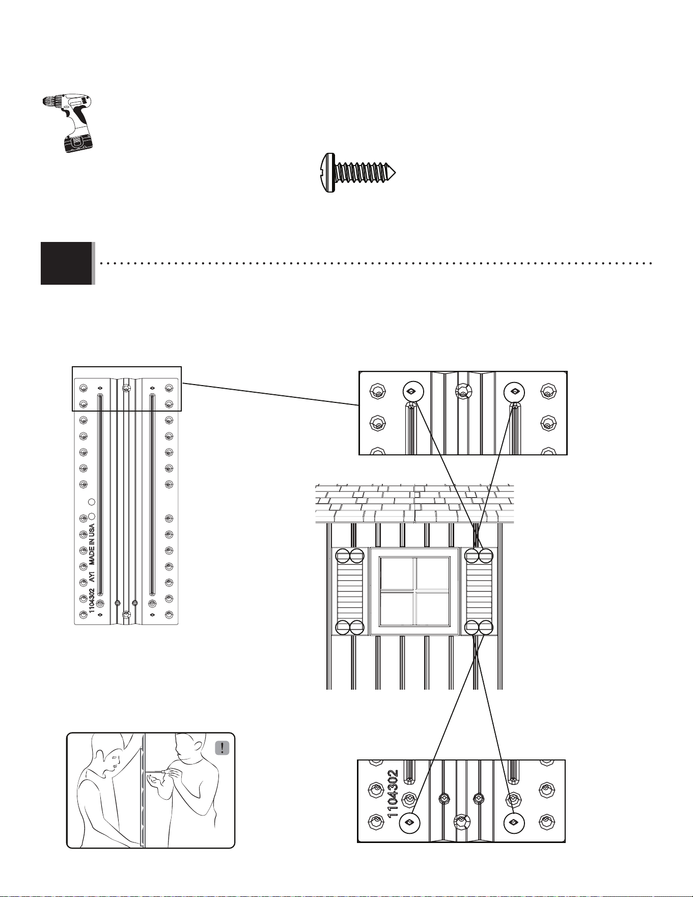
82
TOOLS AND HARDWARE REQUIRED / OUTILS ET QUINCAILLERIE REQUIS / INSTRUMENTAL Y HERRAJE REQUERIDOS
X SECTION 11 (CONTINUED) / SECTION 11 (SUITE) / SECCIÓN 11 (CONTINUACIÓN)
ARV (x7)
• Align the screw bosses in the Shutters (AYI) with the holes in the Wall Panels. Secure both Shutters to the Paneles
using the Screws (ARV) provided.
• Aligner les bossages de montage dans les volets (AYI) avec les trous dans les panneaux muraux. Attacher les deux
volets aux panneaux à l’aide des vis (ARV) fournis.
• Alinear los huecos de montaje en las contraventanas (AYI) con los agujeros en los paneles murales. Sujetar ambas
contraventanas a los paneles usando los tornillos (ARV) provistos.
AYI
11.2
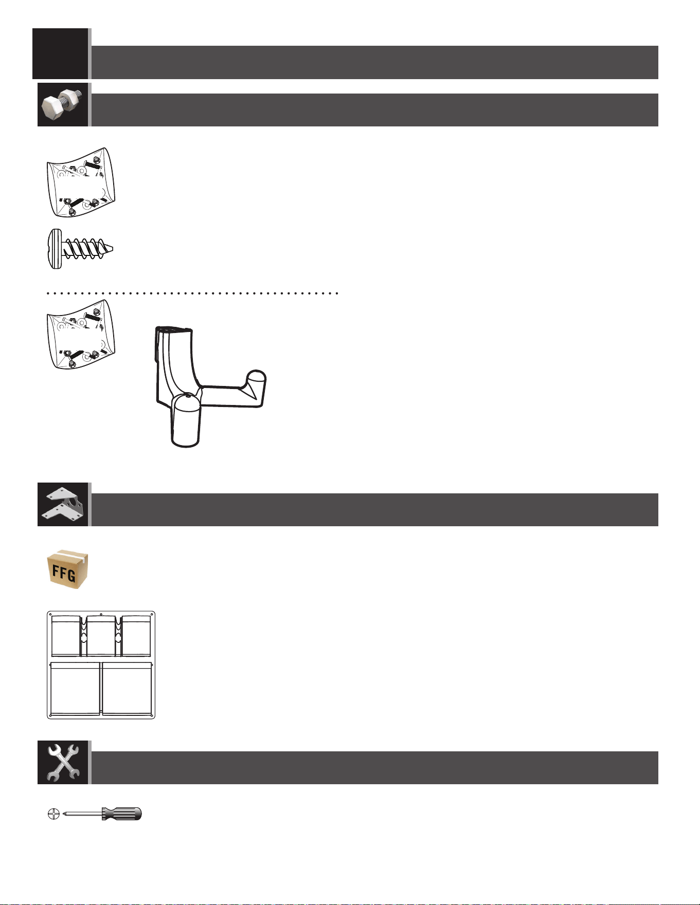
83
WALL HOOK INSTALLATION / INSTALLATION DES CROCHETS / INSTALACIÓN DE LOS GANCHOS
12
ADZ (x7)
EDI (x1)
Large Part / Grande pièce / Pieza grande
Hardware Bags / Sacs de quincaillerie / Bolsas de herraje
TOOLS REQUIRED / OUTILS REQUIS / INSTRUMENTAL REQUERIDO
PARTS REQUIRED / PIÈCES REQUISES / PIEZAS REQUERIDAS
HARDWARE REQUIRED / QUINCAILLERIE REQUISE / HERRAJE REQUERIDO
EDM
EDH
EDL (x6)
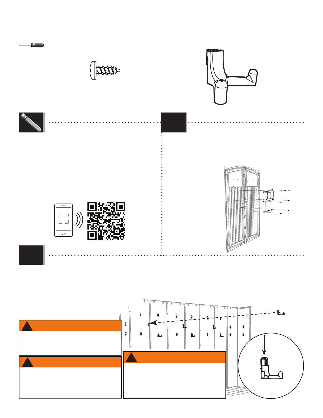
84
TOOLS AND HARDWARE REQUIRED / OUTILS ET QUINCAILLERIE REQUIS / INSTRUMENTAL Y HERRAJE REQUERIDOS
X SECTION 12 (CONTINUED) / SECTION 12 (SUITE) / SECCIÓN 12 (CONTINUACIÓN)
• Secure the Door Pouch (EDI) to the back of the
Right or Left Door using seven (7) Screws (ADZ).
• Attacher le sac à porte (EDI) au côté arrière de la
porte droite ou gauche à l’aide de sept (7) vis (ADZ).
• Sujetar la bolsa para la puerta (EDI) a la cara trasera
de la puerta derecha o izquierda usando siete (7)
tornillos (ADZ).
EDI
ADZ
ADZ
ADZ
• If you have trouble with these steps, follow the code below
to view a how-to video on this section.
• En cas des problèmes avec ces étapes, suivre le code en
bas pour voir un vidéo sur l’assemblage de cette section.
• En caso de algún problema con estos pasos, seguir el
código debajo para ver un video sobre el ensamble en esta
sección.
12.1
12.2
ADZ (x7)
http://go.lifetime.com/doorbaghooks
LIFETIME
©
EDL (x6)
• Insert the six (6) Wall Hooks (EDL) into any of the notches in the Wall Panels (either side of the shed). Then push
downward to lock them in place.
• Insérer les six (6) crochets muraux (EDL) dans les encoches dans les panneaux muraux (soit le côté droit, soit le
côté gauche de l’abri). Ensuite, pousser-les ver le bas pour les attacher bien en place.
• Insertar los seis (6) ganchos murales (EDL) en las muescas en los paneles murales (en cualquiera de los dos lados
de la caseta). Entonces, empujarlos hacia abajo para fi jarlos en su lugar.
EDL
WARNING
The total weight on a wall hook should not exceed
7 lb (3,2 kg) nor more than 30 lb (14 kg) on a wall
panel. Failure to follow this warning could result in
property damage and/or personal injury.
!
AVERTISSEMENT
Le poids total sur un crochet mural ne devrait
pas excéder ≈3,2 kg (7 lb) ou plus de ≈14 kg (30
lb) sur un panneau mural. Le non-respect de cet
avertissement peut entraîner des dommages à la
propriété et/ou des blessures graves.
!
EDL
ADVERTENCIA
El peso total en un gancho mural no debe
exceder de 7 lb (3.2 kg) ni más de 30 lb
(14 kg) en un panel mural. El no seguir esta
advertencia puede resultar en daños a la
propiedad y/o en lesiones graves personales.
!
85
DOOR ALIGNMENT / ALIGNEMENT DES PORTES / ALINEACIÓN DE LAS PUERTAS
13
NO HARDWARE INCLUDED FOR THIS SECTION
AUCUNE QUINCAILLERIE INCLUSE POUR CETTE SECTION
NINGÚN HERRAJE INCLUIDO PARA ESTA SECCIÓN
TOOLS REQUIRED / OUTILS REQUIS / INSTRUMENTAL REQUERIDO
PARTS REQUIRED / PIÈCES REQUISES / PIEZAS REQUERIDAS
HARDWARE REQUIRED / QUINCAILLERIE REQUISE / HERRAJE REQUERIDO
AIX (x4)
Plastic Parts / Pièces en plastique / Piezas de plástico
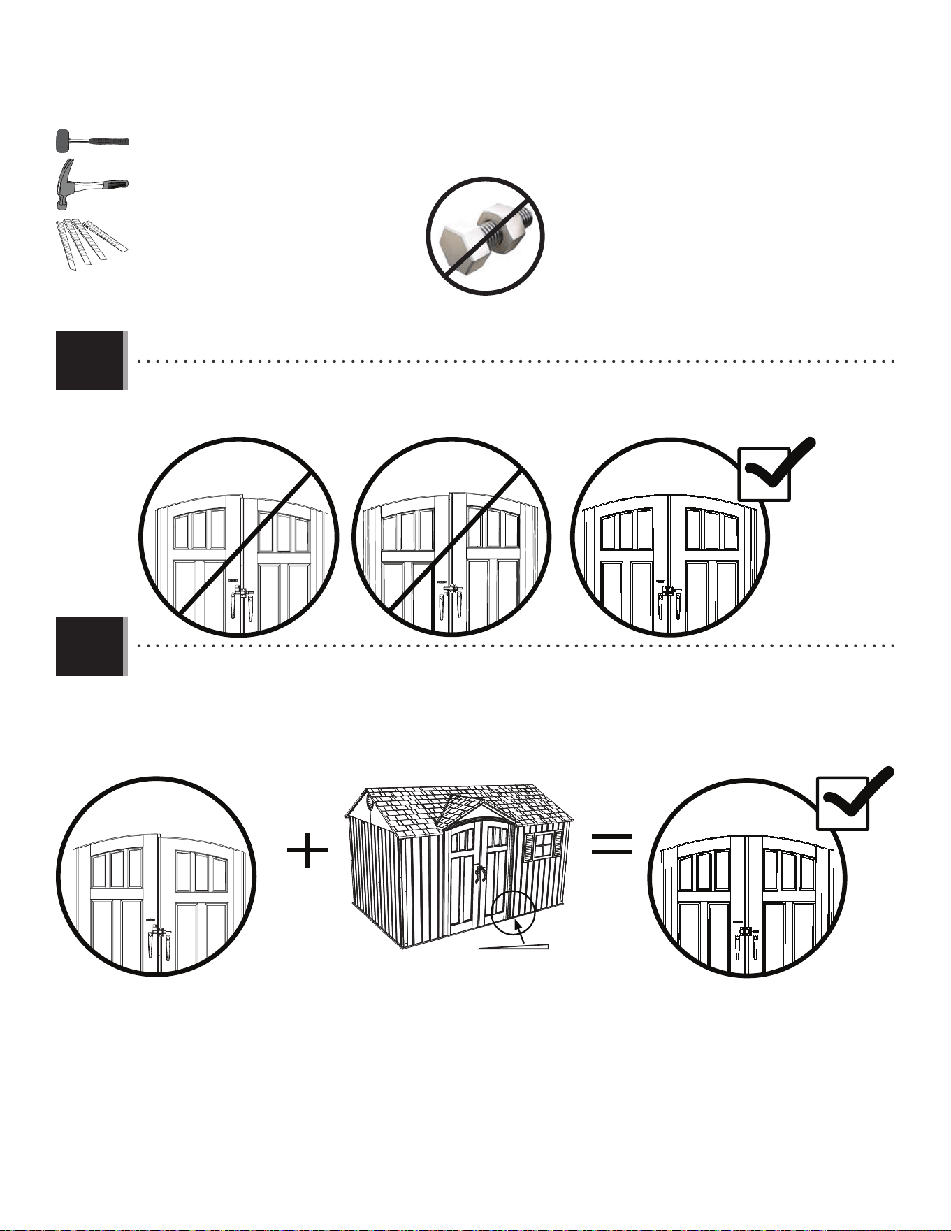
8686
X SECTION 13 (CONTINUED) / SECTION 13 (SUITE) / SECCIÓN 13 (CONTINUACIÓN)
TOOLS AND HARDWARE REQUIRED / OUTILS ET QUINCAILLERIE REQUIS / INSTRUMENTAL Y HERRAJE REQUERIDOS
AIX (x4)
Fig. 1
Fig. 2
AIX
Fig. 3
• If the Doors are not level, follow the steps on this page or the next to even them out.
• Si les portes ne sont pas niveaux l’une avec l’autre, suivre les étapes dans cette page ou la suivante pour les niveler.
• Si las puertas no están niveladas, seguir los pasos en esta página o la siguiente para nivelarlas.
• If the Left Door is higher, insert a Shim (AIX) underneath the right, front and left, rear corners of the Shed until the
Doors are the same height. Break off any excess Shim.
• Si la porte gauche est plus haute, insérer une cale (AIX) sous le coin avant droit jusqu’à ce que les portes restent à
la même hauteur. Détacher de l’excès des cales.
• Si la puerta izquierda es más alta, insertar una cuña (AIX) debajo las esquinas delantera derecha y trasera
izquierda hasta que las puertas queden a la misma altura. Quebrantar cualquier exceso de las cuñas.
13.1
13.2
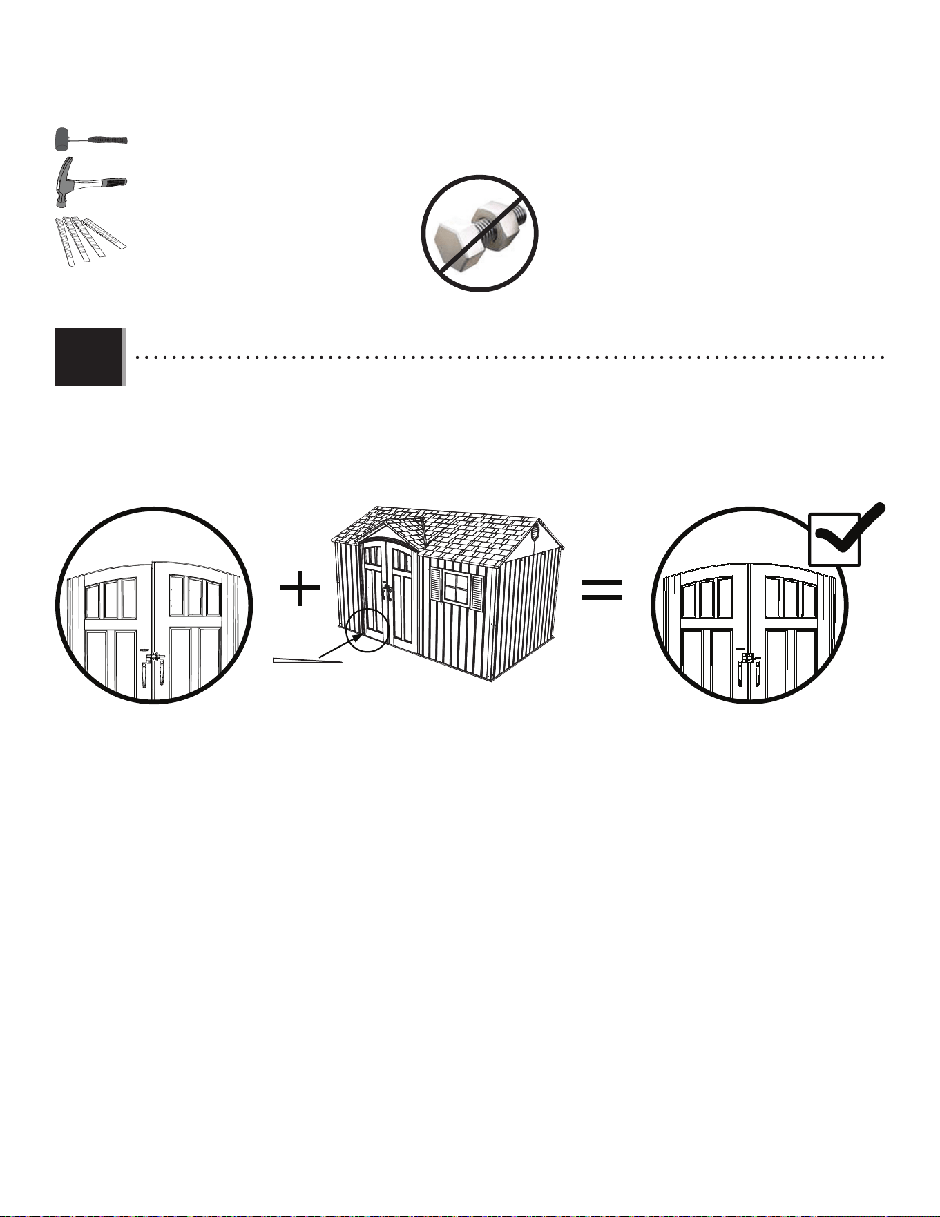
8787
X SECTION 13 (CONTINUED) / SECTION 13 (SUITE) / SECCIÓN 13 (CONTINUACIÓN)
TOOLS AND HARDWARE REQUIRED / OUTILS ET QUINCAILLERIE REQUIS / INSTRUMENTAL Y HERRAJE REQUERIDOS
Fig. 1
Fig. 2
AIX
Fig. 3
• If the Right Door is higher, insert a Shim (AIX) underneath the left, front and right, rear corners of the Shed until the
Doors are the same height. Break off any excess Shim.
• Si la porte droite est plus haute, insérer une cale (AIX) sous les coins avant gauche et arrière droit jusqu’à ce que
les portes restent à la même hauteur. Détacher de l’excès des cales.
• Si la puerta derecha es más alta, insertar una cuña (AIX) debajo las esquinas delantera izquierda y trasera derecha
hasta que las puertas queden a la misma altura. Quebrantar cualquier exceso de las cuñas.
13.3
AIX (x4)
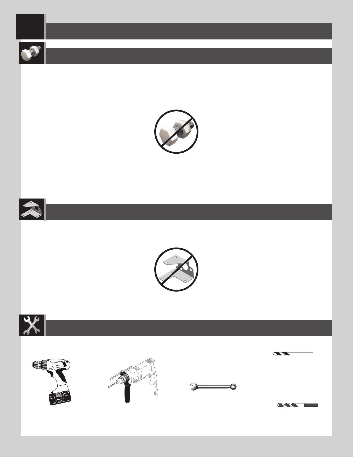
88
SHED ANCHORING / ANCRAGE DE L’ABRI / ANCLAJE DE LA CASETA
14
7/16 in/po (11 mm)
TOOLS REQUIRED / OUTILS REQUIS / INSTRUMENTAL REQUERIDO
PARTS REQUIRED / PIÈCES REQUISES / PIEZAS REQUERIDAS
HARDWARE REQUIRED / QUINCAILLERIE REQUISE / HERRAJE REQUERIDO
5/16" (8 mm) Wood Drill Bit
5/16 po (8 mm) Foret à boit
5/16 in (8 mm) Broca para madera
5/16" (8 mm) Masonry Drill Bit
5/16 po (8 mm) Foret à maçonnerie
5/16 in (8 mm) Broca para albañilería
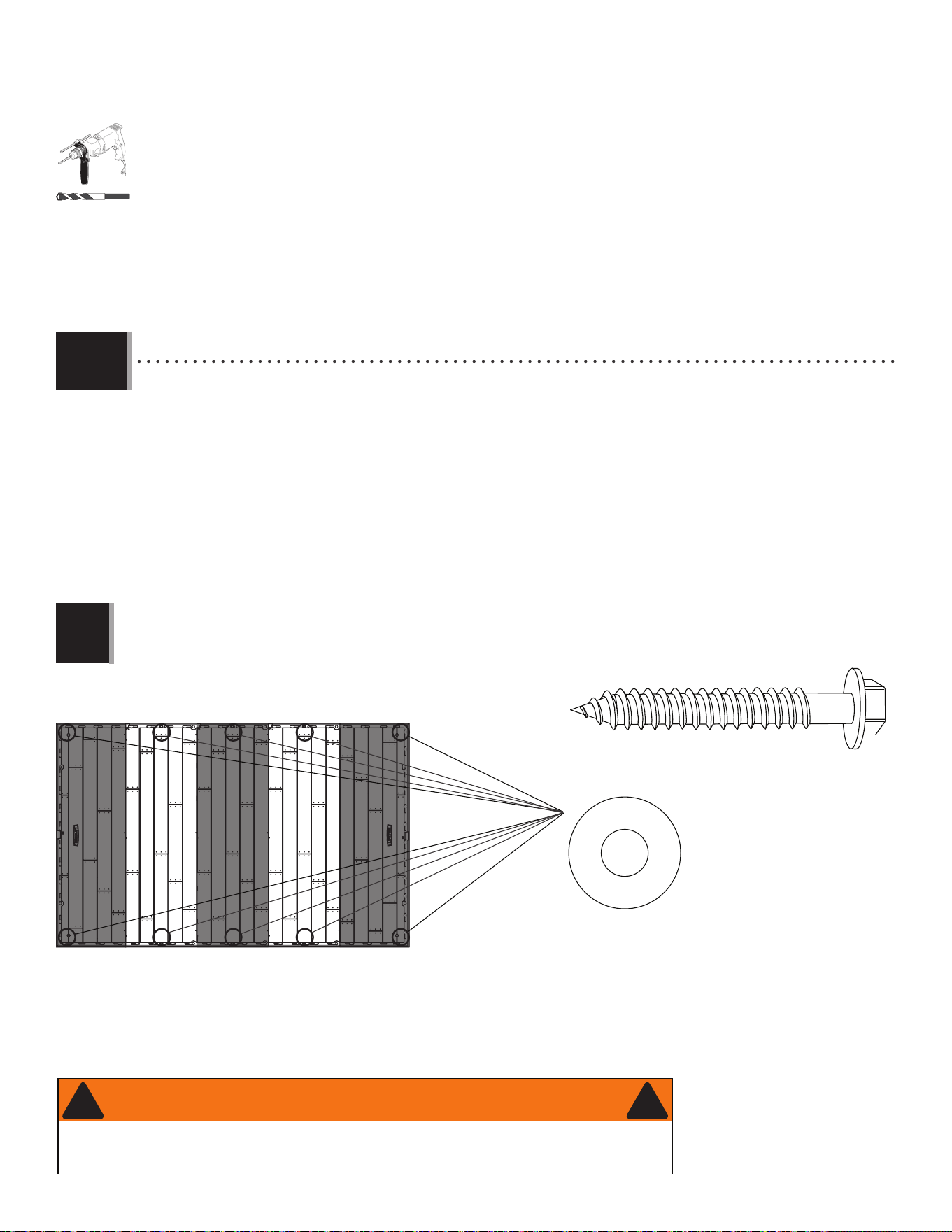
8989
X SECTION 14 (CONTINUED) / SECTION 14 (SUITE) / SECCIÓN 14 (CONTINUACIÓN)
ANCHORING TO A CONCRETE PLATFORM
L’ANCRAGE À UNE PLATE-FORME EN BÉTON
EL ANCLAJE A UNA PLATAFORMA DE CONCRETO
• To anchor your shed, you must purchase the correct anchoring hardware. For a concrete platform, we recommend using
a hammer drill, 5/16" (8 mm) masonry bit, ten (10) 3/8" x 2" (10 mm x 5 cm) Concrete Screws and ten (10) 3/8" x 1"
(10 mm x 2,5 cm) Fender Washers.
• Pour ancrer l’abri, il faut acheter la quincaillerie d’ancrage correcte. Pour une plate-forme en béton, nous recommandons
que l’usage d’une perceuse de percussion, un foret à maçonnerie de 8 mm (5/16 po), dix (10) vis d’ancrage à béton de
10 mm x 5 cm (3/8 po x 2 po) et dix (10) rondelles de protection de 10 mm x 2,5 cm (3/8 po x 1 po).
• Para anclar la caseta, es necesario comprar el herraje de anclaje correcto. Para una plataforma de concreto,
recomendamos el uso de un martillo perforador, broca de albañilería de 8 mm (5/16 in), diez (10) tornillos de anclaje
para concreto de 10 mm x 5 cm (3/8 in x 2 in) y diez (10) rondanas de protección de 10 mm x 2,5 cm (3/8 in x 1 in).
(x10)
(x10)
5/16 in/po (8 mm)
(Not included) (Non inclus) (No incluidos)
(Not included) (Non incluses) (No incluidas)
14.1
• Do not exceed a 3/8" (10 mm) diameter screw. Refer to your local hardware store for this hardware.
• Ne pas dépasser un diamètre de 10 mm (3/8 po). La quincaillerie du coin aura ces accessoires.
• No exceder un diámetro de 10 mm (3/8 po). Referirse a la ferretería local para obtener este herraje.
!
FOR CONCRETE PLATFORM / POUR UNE PLATE-FORME EN BÉTON / PARA UNA PLATAFORMA DE CONCRETO
• Failure to anchor the shed may result in property damage and/or personal injury.
• Si vous n’ancrez pas votre abri, des dommages à la propriété et/ou des blessures peuvent en résulter.
• No anclar la caseta puede resultar en daños a la propiedad y/o en lesiones personales.
WARNING / AVERTISSEMENT / ADVERTENCIA
! !
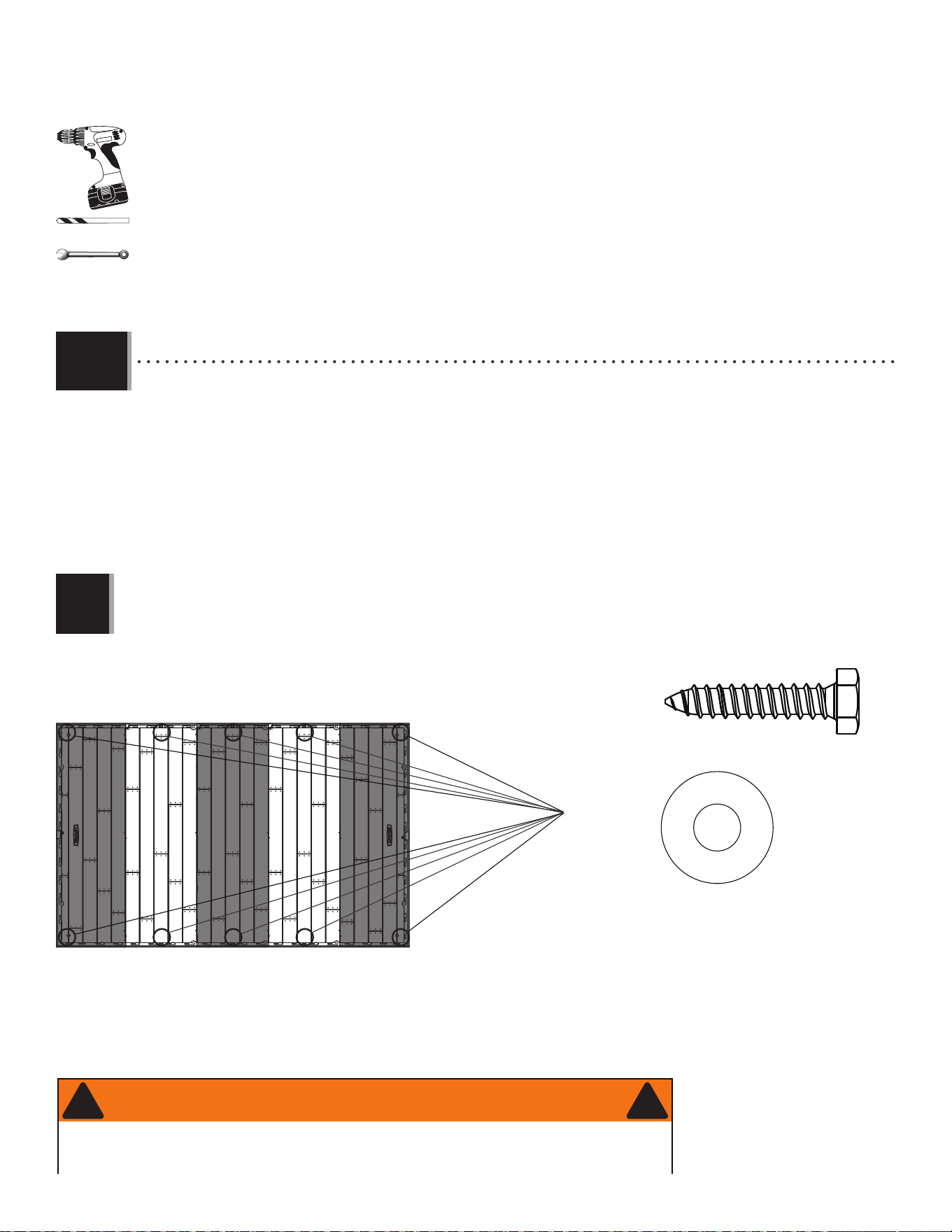
9090
X SECTION 14 (CONTINUED) / SECTION 14 (SUITE) / SECCIÓN 14 (CONTINUACIÓN)
• To anchor your shed, you must purchase the correct anchoring hardware. For a wood-framed platform, we
recommend using a drill, 5/16" (8 mm) drill bit, ten (10) 3/8" x 1 1/2" (10 mm x 4 cm) Lag Screws and ten (10)
3/8" x 1" (10 mm x 2,5 cm) Fender Washers.
• Pour ancrer l’abri, il faut acheter la quincaillerie d’ancrage correcte. Pour une plate-forme en bois, nous
recommandons l’usage d’une perceuse électrique, un foret de 8 mm (5/16 po), dix (10) vis de retard de 10 mm x
4 cm (3/8 po x 1 1/2 po), et dix (10) rondelles de protection de 10 mm x 2,5 cm (3/8 po x 1 po).
• Para anclar la caseta, es necesario comprar el herraje de anclaje correcto. Para una plataforma hecho de hecho
de madera, recomendamos el uso de un taladro eléctrico, una broca de 8 mm (5/16 in), diez (10) tornillos para
madera de 10 mm x 4 cm (3/8 in x 1 1/2 in), y diez (10) rondanas de protección de 10 mm x 2,5 cm (3/8 in x 1
in).
ANCHORING TO A WOOD PLATFORM
L’ANCRAGE À UNE PLATE-FORME EN BOIS
EL ANCLAJE A UNA PLATAFORMA DE MADERA
5/16 in/po (8 mm)
(x10)
(x10)
(Not included) (Non inclus) (No incluidos)
(Not included) (Non incluses) (No incluidas)
14.1
7/16 in/po (11 mm)
• Do not exceed a 3/8” (10 mm) diameter screw. Refer to your local hardware store for this hardware.
• Ne pas dépasser un diamètre de 10 mm (3/8 po). La quincaillerie du coin aura ces accessoires.
• No exceder un diámetro de 10 mm (3/8 po). Referirse a la ferretería local para obtener este herraje.
!
FOR WOOD PLATFORM / POUR UNE PLATE-FORME EN BOIS / PARA UNA PLATAFORMA DE MADERA
• Failure to anchor the shed may result in property damage and/or personal injury.
• Si vous n’ancrez pas votre abri, des dommages à la propriété et/ou des blessures peuvent en résulter.
• No anclar la caseta puede resultar en daños a la propiedad y/o en lesiones personales.
WARNING / AVERTISSEMENT / ADVERTENCIA
! !

91
Congratulations on your Lifetime
®
product purchase. By following the instructions below, your new Lifetime product should provide you with years
of service and enjoyment.
The polyethylene panels are stain and solvent resistant. Most stains can be removed using a mild soap and a soft-bristled
brush. Abrasive cleaning materials may scratch the plastic and are not recommended. Repair scratches or rust spots on the
metal by sanding the affected area lightly; using a rust preventative spray primer; and fi nally, spraying with a high-gloss spray
enamel paint. Avoid placing a direct heat source on or near surfaces unless using a heat barrier.
Nous vous félicitons d’avoir acheté ce produit Lifetime
®
. En suivant les instructions ci-dessous, votre nouveau produit Lifetime devrait vous
fournir des années de service et de plaisir.
Les murs et les étagères en polyéthylène sont résistants aux taches et solvants de nettoyage. Pour les nettoyer, se servir
d’un savon doux et d’une brosse douce. Les produits abrasifs de nettoyage risquent d’égratigner le plastique et ne sont pas
recommandés. Pour réparer les égratignures ou taches de rouille sur le métal, frotter légèrement l’endroit affecté au papier de
verre, puis passer une couche de produit vaporisant préventif, et, enfi n, vaporiser une peinture émail ultrabrillante. Éviter de
placer une source de chaleur directe sur ou près des surfaces, ou les protéger à l’aide d’une protection contre la chaleur.
CLEANING & CARE
NETTOYAGE ET ENTRETIEN
Felicidades por la compra de su producto Lifetime
®
. Al seguir las siguientes instrucciones, su nuevo producto Lifetime le brindará años de servicio
y satisfacción.
Los paneles de polietileno son resistentes a las manchas y solventes. La mayoría de las manchas puede removerse usando un
jabón suave y un cepillo de cerdas suaves. Los materiales abrasivos para limpieza pueden rayar el plástico y no se recomien-
dan. Reparar rayones o manchas de óxido en el metal, lijando suavemente la parte afectada; usando un aerosol preventivo de
óxido y fi nalmente, rociando con una pintura de esmalte brillante. Evitar poner una fuente de calor directa en o cerca de las
superfi cies sin usar una barrera de calor.
LIMPIEZA Y CUIDADO

92
LIFETIME’S PROMISE TO YOU:
We invite you to read our privacy policy at www.lifetime.com
REGISTER today!
At Lifetime
®
, we are committed to providing innovative and quality products. While registering, you will have the opportunity to give us your feedback. Your input is
valuable to us.
• You can also opt in to receive new product notifi cations or promotions.
• In the unlikely event of a product recall or safety modifi cation, your registration provides the information we need to notify you directly.
• Registration is fast, easy, and completely voluntary.
Maintaining your privacy is our long-standing policy at Lifetime
®
. And you can rest assured that Lifetime
®
will not sell or provide your
personal data to other third parties, or allow them to use your personal data for their own purposes.
REGISTER YOUR PRODUCT ONLINE AT WWW.LIFETIME.COM
LA PROMESA DE LIFETIME
®
PARA USTED:
Lo invitamos a leer nuestra política de privacidad en www.lifetime.com (sólo en inglés)
¡REGISTRARSE hoy mismo!
En Lifetime
®
, estamos comprometidos a ofrecer productos innovadores y de calidad. Al registrarse, usted tendrá la oportunidad de darnos su retroalimentación.
Su información es valiosa para nosotros.
• También puede optar por recibir nuestras notifi caciones o promociones.
• En el caso improbable de que el producto deba ser retirado del mercado o que sufra alguna modifi cación, su registro provee la
información que necesitamos para notifi carle directamente.
• El registro es rápido, fácil y completamente voluntario.
Mantener privacidad es nuestra política permanente en Lifetime
®
. Y puede estar seguro que Lifetime
®
no venderá ni dará datos personales a
terceros, ni les permitirá usar datos personales para sus propios fi nes.
REGISTRAR EL PRODUCTO EN LÍNEA EN WWW.LIFETIME.COM
LA PROMESSE DE LIFETIME :
Nous vous invitons à lire notre politique de confi dentialité à www.lifetime.com (en anglais seulement)
ENREGISTRER CE PRODUIT aujourd’hui!
Chez Lifetime
®
, nous nous engageons à fournir des produits innovateurs de qualité. Lors de votre inscription, vous aurez l’occasion de nous faire parvenir vos
commentaires. Votre opinion est importante pour nous.
• On peut également choisir de recevoir des avis ou des promotions dans le cadre de nouveaux produits.
• Dans l’éventualité improbable d’un rappel ou d’un avis de sécurité, l’inscription fournit les renseignements nécessaires nous
permettant de communiquer avec vous.
• L’inscription est rapide, facile et complètement volontaire.
Conserver votre confi dentialité est notre politique de longue date chez Lifetime
®
. Vous pouvez donc être rassuré par le fait que Lifetime
®
ne
vendra pas ou ne fournira pas vos données personnelles à des tiers, et ne leur permettra pas d’utiliser vos données personnelles à leurs
propres fi ns.
ENREGISTRER CE PRODUIT EN LIGNE À WWW.LIFETIME.COM

93
THE MANUFACTURER RESERVES THE RIGHT TO MAKE SUBSTITUTIONS TO WARRANTY CLAIMS IF PARTS ARE UNAVAILABLE OR OBSOLETE.
1. Lifetime outdoor sheds are warranted to the original purchaser to be free from defects in material or workmanship
for a period of ten years from the date of original retail purchase. The word “defects” is defi ned as imperfections that
impair the use of the product. Defects resulting from misuse, abuse or negligence will void this warranty. This warranty
does not cover defects due to improper installation, alteration or accident. This warranty does not cover damage caused
by vandalism, rusting, “acts of nature” or any other event beyond the control of the manufacturer.
2. This warranty is nontransferable and is expressly limited to the repair or replacement of defective product. If the
product is defective within the terms of this warranty, Lifetime Products, Inc. will repair or replace defective parts at
no cost to the purchaser. Shipping charges to and from the factory or distribution center are not covered and are the
responsibility of the purchaser. Labor charges and related expenses for removal, installation or replacement of the shed
or its components are not covered under this warranty.
3. This warranty does not cover scratching or scuffi ng of the product that may result from normal usage. In addition,
defects resulting from intentional damage, negligence, unreasonable use or hanging from the truss will void this warranty.
4. Liability for incidental or consequential damages is excluded to the extent permitted by law. While every attempt is made
to embody the highest degree of safety in all equipment, freedom from injury cannot be guaranteed. The user assumes
all risk of injury resulting from the use of this product. All merchandise is sold on this condition, and no representative
of the company may waive or change this policy.
5. This product is not intended for institutional or commercial use; Lifetime Products, Inc. does not assume any liability for
such use. Institutional or commercial use will void the warranty.
6. Our goods come with guarantees that cannot be excluded under the Australian Consumer Law. You are entitled to a
replacement or refund for a major failure and for compensation for any other reasonably foreseeable loss or damage.
You are also entitled to have the goods repaired or replaced if the goods fail to be of acceptable quality and the failure
does not amount to a major failure.
7. This warranty is expressly in lieu of all other warranties, expressed or implied, including warranties of merchantability
or fi tness for use to extent permitted by Federal and state law. Neither Lifetime Products, Inc., nor any representative
assumes any other liability in connection with this product. This warranty gives you specifi c legal rights, and you may
also have other rights which vary from state to state
(or province to province, as applicable in Canada).
www.lifetime.com
PLEASE INCLUDE YOUR DATED SALES RECEIPT AND PHOTOGRAPHS OF DAMAGED PARTS.
REPORT PRODUCT DEFECTS IN WRITING TO:
Lifetime Products, Inc., PO Box 160010 Clearfi eld, UT 84016-0010
or call 1-800-225-3865 M–F 7 a.m. to 5 p.m. MST.
REGISTER YOUR PRODUCT FOR QUICKER CUSTOMER SERVICE.
Visit www.lifetime.com or call 1-800-225-3865 to register your product today.
FOR INTERNATIONAL WARRANTY CLAIMS:
All warranty claims must be accompanied by a sales receipt. Report all warranty claims in writing to your regional sales
support representative. Please include your dated sales receipt and photographs of damaged parts.
To Identify the representative for your region, please visit: www.lifetime.com/international
10-YEAR LIMITED FACTORY WARRANTY
W
A
R
R
A
N
T
Y
W
A
R
R
A
N
T
Y
WARRANTY

94
LE FABRICANT SE RÉSERVE LE DROIT DE FAIRE DES SUBSTITUTIONS EN CAS DE RECOURS EN GARANTIE SI LES PIÈCES NE SONT PAS
DISPONIBLES OU SONT OBSOLÈTES.
1. Les abris extérieurs Lifetime
©
sont garantis à l’acheteur d’origine contre tous défauts de matériau ou de fabrication pendant
une durée de dix (10) ans à partir de la date d’achat d’origine. Le mot « défauts » signifi e des défectuosités qui empêchent
l’utilisation du produit. Les défauts résultant de mauvais usage, d’abus ou de négligence annulent cette garantie. Cette garantie
ne couvre pas les dommages causés par le vandalisme, la rouille, « les catastrophes naturelles » ou tout autre événement en
dehors du contrôle du fabricant.
2. Cette garantie n’est pas transférable et est expressément limitée à la réparation ou au remplacement du produit défectueux.
Si le produit est déclaré défectueux selon les termes de cette garantie, Lifetime
©
Products, Inc. réparera ou remplacera les
parties défectueuses gratuitement pour l’acheteur. Les frais d’expédition aller et retour de l’usine ne sont pas couverts et sont à
la charge de l’acheteur. Les frais de main-d’œuvre et frais associés à l’enlèvement, au montage ou au remplacement de l’abri
ou de ses composants ne sont pas couverts par cette garantie.
3. Cette garantie ne couvre pas les égratignures ou érafl ures du produit résultant d’une utilisation normale. Par ailleurs, les
défectuosités résultant de dommages intentionnels, négligence, utilisation abusive ou suspension à partir de l’entretoise annulent
cette garantie.
4. Toute responsabilité pour dommages incidents ou conséquents est exclue dans la mesure permise par la loi. Bien que toutes
les mesures aient été prises pour intégrer le plus haut degré de sécurité dans l’ensemble du matériel, l’impossibilité de blessure
ne peut pas être garantie. L’utilisateur assume tous les risques de blessure résultant de l’utilisation de ce produit. L’ensemble
de la marchandise est vendu en vertu de cette condition et aucune personne représentant la société ne peut déroger à cette
politique, ni la modifi er.
5. Ce produit n’est pas prévu pour l’usage institutionnel ou commercial; Lifetime
©
Products, Inc. n’assume aucune responsabilité
pour un tel usage. L’utilisation institutionnelle ou commerciale annulera cette garantie.
6. Nos articles sont offerts avec des garanties qui ne peuvent connaître d’exclusions en vertu de la loi australienne sur la protection
des consommateurs. Vous avez droit au remplacement ou au remboursement en cas de défaillance majeure de votre article ainsi
qu’à une compensation en cas de perte ou de dommage prévisible. Vous avez aussi droit à la réparation ou au remplacement
de l’article s’il n’est pas d’une qualité acceptable et que la défaillance n’est pas majeure.
7. Cette garantie remplace expressément toutes les autres garanties, expresses ou tacites, y compris les garanties de
commercialisation ou d’adaptation à un but particulier dans la mesure permise par les lois fédérales et des états. Ni Lifetime
©
Products, Inc. ni aucun de ses représentants n’assure d’autre responsabilité concernant ce produit. Cette garantie vous accorde
des droits particuliers, et vous aurez peut-être d’autres droits qui varient d’un état à l’autre (ou d’une province à l’autre, selon
le cas au Canada).
www.lifetime.com
TOUS LES RECOURS EN GARANTIE DOIVENT ÊTRE ACCOMPAGNÉS DU REÇU DE VENTE.
FAIRE PARVENIR PAR ÉCRIT UN RAPPORT PAR ÉCRIT DE DÉFECTUOSITÉ DU PRODUIT À :
Lifetime Products, Inc., PO Box 160010 Clearfi eld, UT 84016-0010
ou composer 1-800-225-3865 lundi à vendredi 7 h – 17 h (HNR)
ENREGISTRER VOTRE ARTICLE À :
www.lifetime.com, ou composer 1-800-225-3865 pour enregistrer votre article aujourd’hui.
POUR RECOURS EN GARANTIE INTERNATIONAUX :
Tous les recours en garantie doivent être accompagnés du reçu de vente. Faire parvenir par écrit un rapport par écrit de
défectuosité du produit au représentant régional de ventes. Veiller inclure votre reçu de vente daté et les photographies des
pièces endommagées. Pour identifi er le représentant régional, visiter www.lifetime.com/international
GARANTIE DE FABRICATION LIMITÉE DE 10 ANS
G
A
R
A
N
T
I
E
G
A
R
A
N
T
I
E
GARANTIE

95
EL FABRICANTE SE RESERVA EL DERECHO DE HACER SUSTITUCIONES EN LOS ELEMENTOS REEMPLAZADOS BAJO GARANTÍA SI LAS PIEZAS
NO ESTÁN DISPONIBLES O SON OBSOLETAS.
1. El comprador original recibe la garantía de que las casetas Lifetime estarán libres de defectos de material o de mano de obra
por un período de 10 años a contar desde la fecha de la compra original. La palabra “defectos” se defi ne como imperfecciones
que perjudican el uso del producto. Los defectos emergentes de un mal uso, abuso o negligencia invalidarán esta garantía. Esta
garantía no cubre defectos debidos a una instalación o alteración incorrecta o a un accidente. Esta garantía no cubre daños
causados por vandalismo, oxidación, “actos de la naturaleza” u otros eventos que estén más allá del control del fabricante.
2. Esta garantía es intransferible, y queda expresamente limitada a la reparación o reemplazo de los productos defectuosos. Si
el producto se encuentra defectuoso dentro de los términos de esta garantía, Lifetime Products, Inc. reparará o reemplazará
las piezas defectuosas sin costo alguno para el comprador. Los gastos de envío hacia y desde la fábrica no están cubiertos, y
quedan bajo la responsabilidad del comprador.
3. Esta garantía no cubre raspaduras ni marcas en el producto que pueden resultar de su uso normal. Además, los defectos
causados por daños intencionales, negligencia, uso irrazonable o por colgarse de las cabriadas invalidarán esta garantía.
4. La responsabilidad por daños incidentales o consecuentes queda excluida hasta el punto en que lo permita la ley. Si bien se
hace el mayor esfuerzo posible para lograr el más alto grado de seguridad en todos nuestros equipos, no puede garantizarse la
libertad de cualquier tipo de lesión. El usuario asume todos los riesgos de lesiones emergentes del uso de este producto. Toda
nuestra mercadería se vende bajo esta condición, y ningún representante de la compañía puede anular ni cambiar esta política.
5. Este producto no está pensado para el uso institucional ni comercial; Lifetime Products, Inc. no asume ninguna otra
responsabilidad en conexión con este producto. El uso institucional o comercial invalidará la garantía.
6. Nuestros productos vienen con garantías que no se pueden excluir bajo la Ley del consumidor de Australia. Ustedes están
autorizados para reemplazarlos u otorgar una devolución o reembolso en caso de falla mayor yen compensación por cualquier
otra falla o daño previsibles. También, están autorizados para hacer reparar los productos o reemplazarlos si éstos no cumplen
con una calidad aceptable y si la falla no es motivo de una defi ciencia mayor.
7. Esta garantía se otorga en reemplazo expreso de toda otra garantía, expresa o implícita, incluidas las garantías de
comercialización o adaptación para el uso en la medida permitida por las leyes federales y estatales. Ni Lifetime Products, Inc.,
ni ninguno de sus representantes asume ninguna otra responsabilidad en conexión con este producto. Esta garantía le otorga
derechos legales específi cos, y usted puede tener otros derechos que varían de estado a estado (o de una provincia a otra,
según corresponda en Canadá).
www.lifetime.com
TODOS LOS RECLAMOS DE GARANTÍA DEBEN ESTAR ACOMPAÑADOS POR UN RECIBO DE COMPRA
INFORME POR ESCRITO LOS DEFECTOS EN EL PRODUCTO A:
Por favor, incluir el recibo de compra fechado y fotografías de las piezas dañadas.
Lifetime Products, Inc., PO Box 160010 Clearfi eld, UT 84016-0010,
o marcar al 1.800.225.3865 de lunes a viernes de 7:00 h hasta 17:00 h (Hora de las Montañas)
REGISTRAR SU PRODUCTO
Visitar nuestra página en Internet www.lifetime.com, o marcar al 1.800.225.3865 para registrar el producto hoy.
PARA RECLAMOS DE GARANTÍA INTERNACIONALES:
Todos los reclamos de garantía deben estar acompañados por un recibo de compra. Informar por escrito todos los
reclamos de garantía a su representante regional de ventas. Favor de incluir el recibo de compra fechado y fotografías de
las piezas dañadas.
Para identifi car el representante regional, visitar www.lifetime.com/international
NINGUNA GARANTÍA OFRECIDA POR EL FABRICANTE ES VÁLIDA EN MÉXICO
GARANTÍA DE FÁBRICA LIMITADA POR 10 AÑOS
G
A
R
A
N
T
Í
A
G
A
R
A
N
T
Í
A
GARANTÍA
96
www.lifetime.com
Or call: 1-800-424-3865
7:00 am–5:00 pm (M–F) MST and 9:00 am–1:00 pm Saturday MST
To purchase accessories or other Lifetime
®
products, visit us at:
www.lifetime.com
O marcar al 1-800-424-3865
De lunes hasta viernes 7:00 h–17:00 h Horario Éstandar de la Montaña (MST) y sábados 9:00 h–13:00 h (MST)
Para comprar accesorios u otros productos de Lifetime®, visitarnos en:
www.lifetime.com
ENHANCE YOUR LIFETIME
®
PURCHASE BY ADDING ACCESSORIES OR OTHER GREAT PRODUCTS
MEJORAR LA COMPRA DE LIFETIME
®
AGREGANDO ACCESORIOS U OTROS MARAVILLOSOS PRODUCTOS
Ou composer le 1-800-424-3865
Du lundi au vendredi de 7 h à 17 h, HR et le samedi de 9 h à 13 h, HR
Pour acheter des accessoires ou des autres produits Lifetime
®
, visiter le :
www.lifetime.com
AMÉLIORER L’ACHAT LIFETIME
®
EN AJOUTANT DES ACCESSOIRES OU D’AUTRES PRODUITS