

GASOLINE HAMMER & DRILL
ITEM: 66077-XP
OWNER'S MANUAL AND SAFETY INSTRUCTIONS
SE THIS MANUAL: KEEP THIS MANUAL FOR SAFETY WARNINGS, PRECAUTIONS, ASSEMBLY,
OPERATING, INSPECTION, MAINTENANCE AND CLEANING PROCEDURES. WRITE THE PRODUCT'S
SERIAL NUMBER ON THE BACK OF THE MANUAL NEAR THE ASSEMBLY DIAGRAM (OR MONTH
AND YEAR OF PURCHASE IF PRODUCT HAS NO NUMBER)
FOR QUESTIONS PLEASE CALL OUR CUSTOMER SUPPORT: 909.628.0880 MON-F 9AM TO 3PM PST
Directory
l
N
a
c
o
f
ma
j
or part
----------------------------------------------------------------------------------------
(
3
)
11
l
nstruction of sa operat
ion
--------------------
-------------------
-------------------
------------------
(
4
)
I
ll M
ain use and a
t
ure
--------------------------------------------------------------
----------------------
(
5
)
I
V
P
reparatory wor
k
bere use
---------------------
--------------------
----------------------------------
(
5
)
V
O
p
c
rati on
(
S
tart
)
-------------------------------------------------------------------------------------------
(
6
)
VI
O
peration
V
I
I
O
peration
(
S
top machine
)
---
··
------
--------
·
---
--
------
------------------------------------------------------
---1
V
I
II
T
echnical maintenance
-------------------
-
--------------------------------------------· ---------------------------1
I
X
failure analysis and
tr
o
ub
le method
-------
---------------------------------------------
-------------------------
1
X
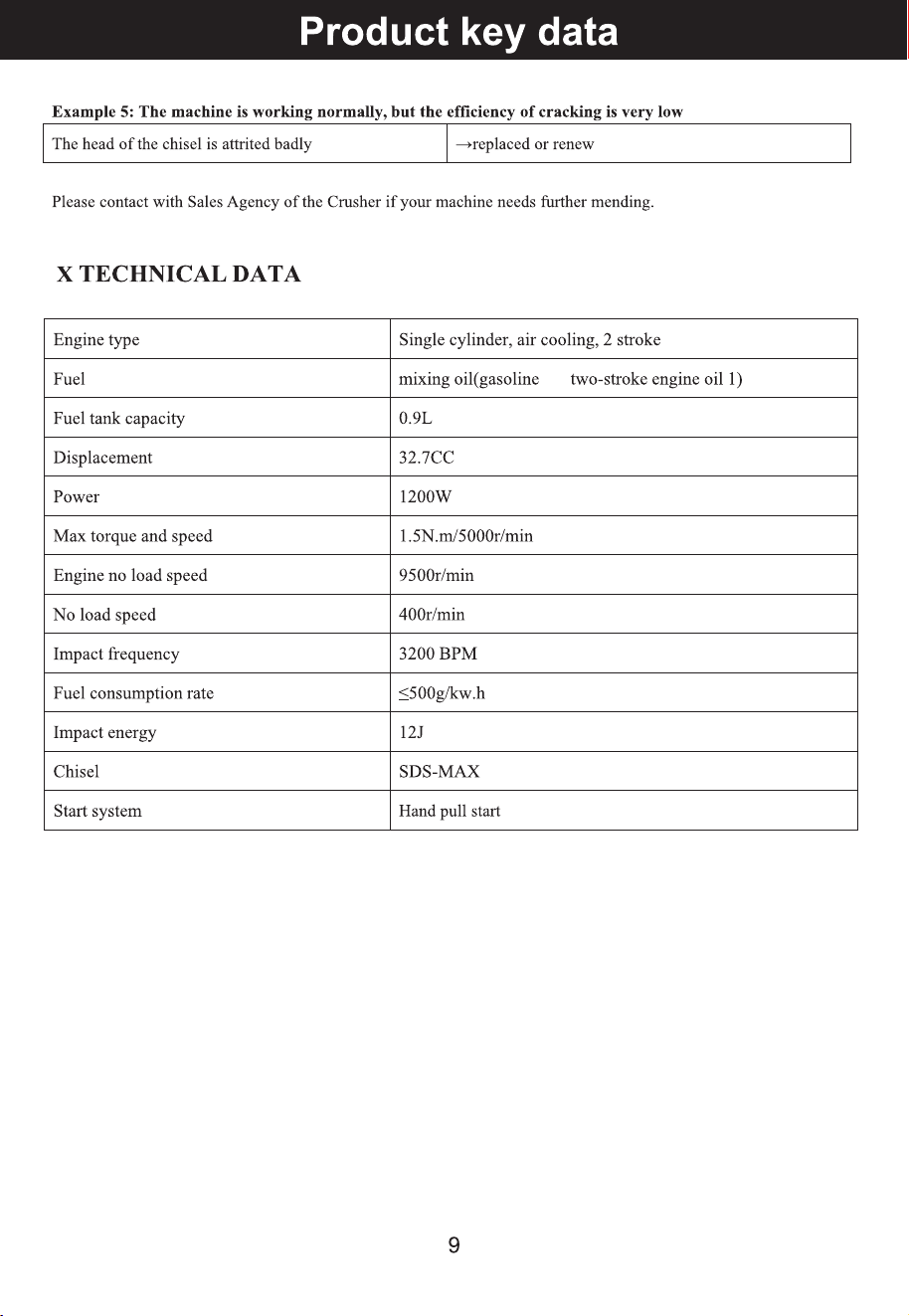
Pro
d
uct key d
a
t
a
•··············
·
···························································································
·
··1
XI Ma
intenance cycle
•··-··-··-·-··-··-·-··-··-·-····-·-··-··-·
-····-··-····-··-····-··-····-·-···-·-··-··-·
(
I 0
)
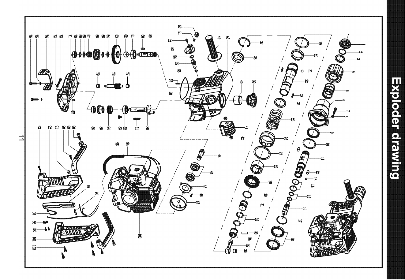
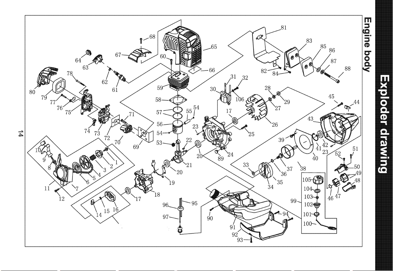
XII
Exploder d
r
a
wing
o
nd parts list
•·-··-·-···-··-·-·
·-··-·-··--·-··-·
·-·-··-··-·-··-··-·-··-··-·-··
(
11
•
l
5
)
XII
S
ervice
•·-·-··-··-·-··-··-·-··-··-·-··-··-·-·· •-··-····-··-·-··-··-····-··-····-··-····-•·-····-··-····-
(
l 6
)
2
PART
I
N
FORMATIO
N
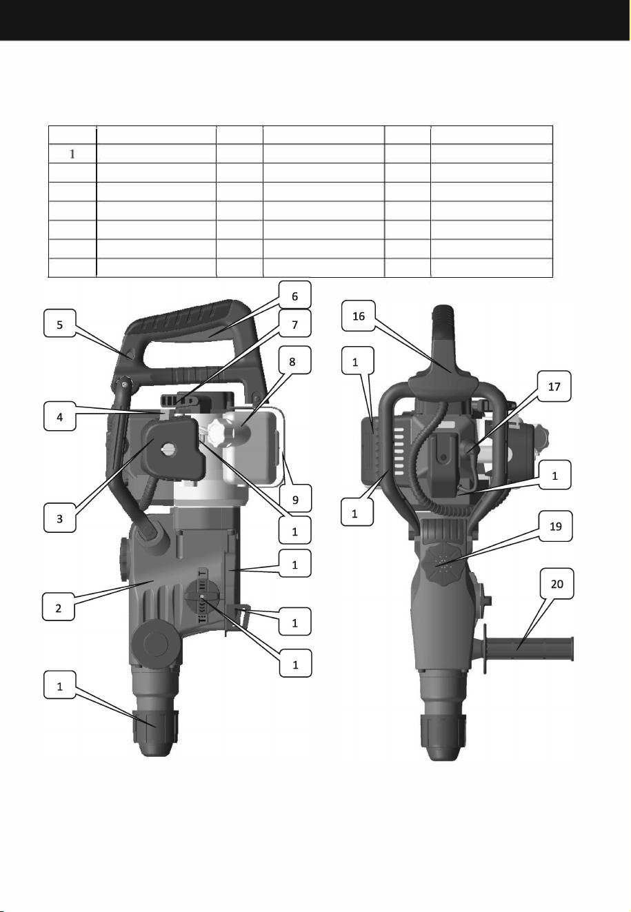
I name of major part
No
Pts name
No
Parts name
No
Parts name
Slide clamp set
2
Gera box assy
3 Air lter
4
Ventilation door
5
Stop switch
6
Throttle switch
7
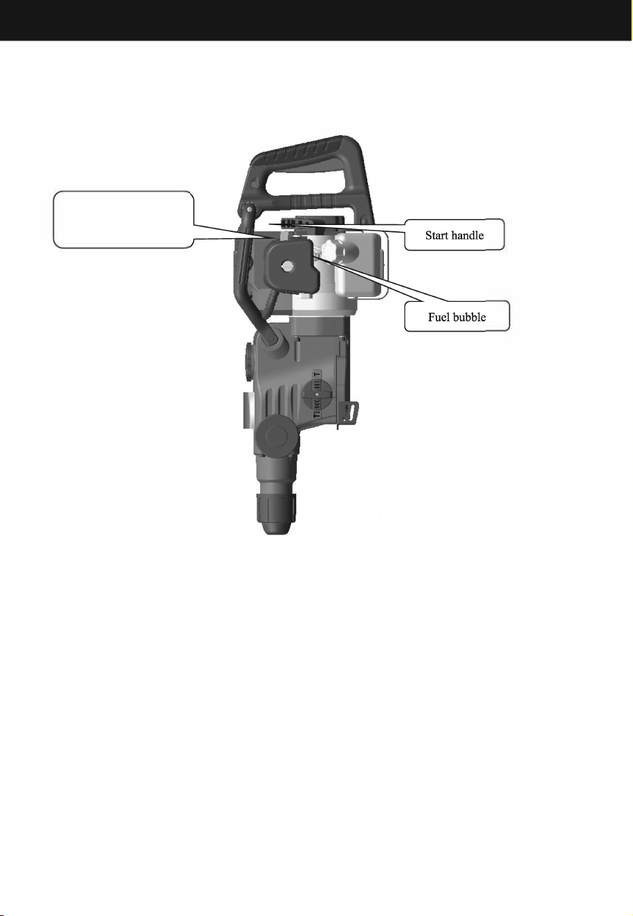
Start handle
8
Fuel
tank 9
Fuel ta bracket
10
Fuel oil bubble
11
Gear box cover
12
Bend plate
13
Adjusting knob
14
Joint lever
15
Muer
16
Main handle
17
Spark plug
18
Tottle rope
19
Lid
20
Side handle
3

Instruction of safe operation
II Instruction of safe operation
2.1 Workplace
2.1.1 Keep the work place open and bright. Chaos, crowded and dark eld can cause accidents.
2.1.2 Don't in anable and explosive, such as a anable liquid, gas or dust environment or use the
machine operation. Machine sparks can ignite dust or gas.
2.1.3 Non-work personnel should stay away om the operating area in case of inj.
2.1.4 In the rests, mountains, grasslands and other wild eld, when using the machine must be (caused by
high temperature machine emissions) re prevention meases.
2.2 Personal Safety
2.2.1 Stay alert, when operating the machine in operation and attention is in stay awake. Don't in the tired,
gs, alcohol, or eatment response under operating e machine. During e machine operation energy
dispersion can cause serious personal injury.
2.2.2 Use saty equipment. Always wear goggles. Saty devices, such as the appropriate conditions of dust
masks, antiskid saty shoes, saty helmet, hearing protection devices can reduce personal injy.
2.2.3 Dress appropriately. Don't wear loose clothes or accessories. The hair, clothes and sleeve away om
moving parts. Loose clothing, accessories, and the hair will be involved in the moving parts.
2.2.4 Used as tools to provide the auxiliary handle. Miss operation can lead to personal saty.
2.2.5 Watch yo step when using, keep body balance. Aer the machine start, shall not be one-handed
operation of this machine.
2.3 The use of the gasoline engine and the matters needing attention
2.3.1 Gasoline ammable, should be in a well ventilated environment r reeling. Come on, please close the
gasoline engine.
2.3 .2 Please do not too much oil, shall not exceed the tank ller neck. If there is a el oil spill, need el
volatilization completely bere start e machine.
2.3 .3 In the storage area to store gasoline, must eliminate re hazard source or Mars.
2.3.4Oil reeling, tighten the cover, the work process oen should check whether there is damage to oil gas, if
damaged, iediately stop the replacement.
2.3.5 Every time bere use, please be sure to check the tting stening screws are tight, ifloose, must be to
use screw stening.
2.3.6 When improve machine, can not throw the throttle handle, let the machine run idle.
2.3.7 Handle should be kept dry, clean, no oil or el mixture
2.3.8 If midway stop operation; Be sure to shut down the engine.
2.3.9 Fuel to ban the use of pure gasoline (no two-soke engine oil), should be in proportion of 4.2 el
reconend against the use.
2.3.10 In a closed area, such as tnel, ditch and a deep ditch work environment when using e machine, must
ensure that esh air is enough. The waste gas containing carbon monoxide. Shall be provided with
ventilating fan r ventilation.
2.3 .11 Ban rapid acceleration or braking, avoid damage to the machine.
2.3.12 Bere transportation, should be emptying the tank el, prevent leakage.
2.3 Maintenance
Non-prossional maintenance personnel removal machine is rbidden, in order to avoid cause structural
damage to parts, shorten the service li of the driver, or cause an accident.
4

2.3 O
p
eratin
g
Mode
Time to switch om the hammer, hammer ill, drill nction ob in shown in
e 3 ", "rotation has
received the required operating mode. (note: must select operation mode under e condition of e engine
stopped.)
Hammer
Image 3
III Main use and feature
3.lUse
Drill
This machine is suitable r the concrete and bricks and rock hammer drill or chisel on homework.
3.2Feature
3.2.1 This product is lighter in weight, low emissions of gasoline engine type hammer/drill.
3.2.2This product conrms to e man-machine engineering design, e greatest degree reduces the operator
working strength, easy to operate, comrtable. Operator can achieve 360 - degree work.
3.2.3 C adjust the impact energy d impact number, applicable to vious bit less than 40 mm in diameter.
3.2.4 Advantage: can save with heavy equipment, such as generator, air compressor, trucks.
IV Preparatory work bere use
4.2Fuel
Use more an 90 # gasoline and special two-stroke engine oil
Recommend the proportions
Condition Gasoline: Engine oil
Run within 20 hours
R aer 20 hours
4.2.1 Banning the use of pure gasoline (without two-soke engine oil) as a el.
4.2.2 Add el In a well ventilated place
20:1
25:1
4.2.3 Please do not too much oil in el tank, please do not over the neck of the el ta ller. If el
overow,must remove the el or el volatilization completely restart the engine
4.2.4 Go aer tighten the el tank lid.
5
Operation
V start
5.1 bere starting the new machine. Repeat the transparent cup is ll oil el oil bubble(image 4),makes the
cburetor ll it up with el.
Choke(Close when cold
start)
lmage4
5.2 Machine lie at on the ground,one hand operation handle, another hand quickly pull stter handle 50
centimeters. Please do not make e handle in the process of repeated pull rebound,hold the handle,to prevent the
rapid rebound in order to protect the starter
5.3 Aer starting the gasoline, completely open the throttle.
VI Run
6.1 Idle speed gasoline engine stting and running r 3 to 5 minutes, preheat machine.
6.2 When gasoline engine has been preheated, according to the impact energy required, put the
throttle control the press the right hand position. Note: in the rst 24 hours, using the machine work
should give priority to with low speed, unavailability of maximum throttle: In order to prolong
service li.
6
Technical maintenance
6.3 Gasoline engine speed conol in medi speed gears.
6.4 Prohibited in the non-work state operating the machine at a high speed.
VII Stop machine
7.1 Loosen the throttle handle, the machine idle r 3 to 5 minutes
7.2 Down by the ameout switch button until the engine stalled. Flame out switch position as shown in gure
1
VIII Technical maintenance
8.1 Air Filter
Check the air lter regularly. Air lter cartridge dust jams will reduce engine power and shorten the
service li of the cylinder. If the lter caridge is dirty, you must use warm water and detergent, clean with a
dry cloth to wipe dry aer installation. If there is any breakage, the lter must be replaced. Especially in dusty
work environment, maintenance cycle is shorten appropriately.
8.2 Fuel lter
If the el lter blockage, machine speed decline, impact can be reduced. Methods: (1) open the lid, with a
metal hook the hook out of the tank and clean el lter (2) when clean el lter, and clean el tank.
8.3 Carburetor
The el ta and cburetor oen have residual oil. Over time, the residual oil into e oil. Residual oil can
jam the oil , the engine won't start. Therere, when the machine idle r more than a week, you must put the
el vent. Methods: pull into the carburetor el oil am rubber tubing to repeat compressions bubble
discharge of oil, el oil in the oil bubble and re pipe put dry aer plugged into e tubing.
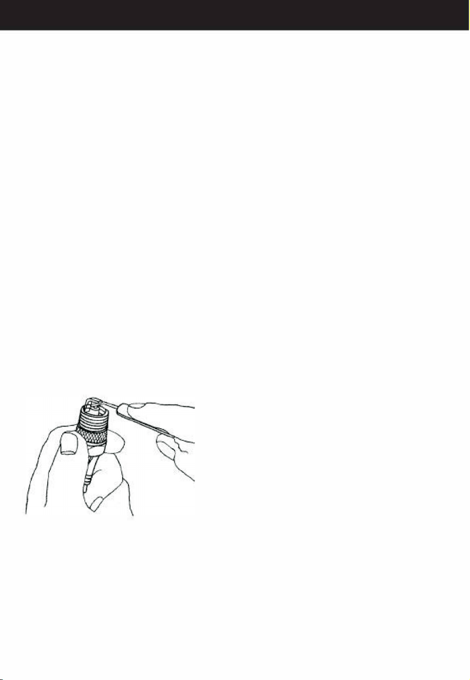
8.4 Spark plug
To ensure the normal operation of the engine, reasonable spark plug gap is 0.5 -0.7 mm. Use steel wire brush
to clean carbon deposit. See image 5.
Image 5
8.5 Muer
Regular cleansing dirt or use detergent to clean the silencer muer import and export in the dirt.
8.6 Cylinder and gear lubrication
7

Failure analysis
cylinder lubrication: unscrew grease cover counterclockwise (see gure 2), join special cylinder hammer picks
30 grams of t, then grease cover clockwise to tighten.
Gear lubrication: with Allen wrench unscrew gearbox cover screws (see gure 1 ), in the adjacent ge parts
add 2 lithium grease 50 grams, then install the gearbox cover in place.
8.7Cylinder cooling n
Remove dust regularly, to ensure that the cylinder heat dissipation is good. The iver r the air cooling type.
Cylinder radiator dust will directly aect the heat dissipation eect.
IX Failure analysis and troubleshooting methods
Problems analysis and solving
Examplel: diculties in starting engine in cooling state.
I
Whether the spark plug is moiste.
I
Dry the igniter plug
Whether e spark plug produces electric spark
replace the igniter plug
I
Too much el absorbed
I
lessen the el supply
Example 2: Diculties in restarting after a sudden stop
Whether el runs out or the Carburetor is blocked
Rell el tank or clean the carburetor
I
Whether the el lter is blocked
I
clean the el lter
I
Too much carbon deposit in igniter plug
I
Remove carbon deposit
Example 3: Reluctance in speeding and weakness in power
Carbon deposit cover the entrance of the cylinder or silencer
Whether the oil tube and the air vent on the el Tank cover
is blocked
I
Blockage in air lter
Example 4: abnormal sound
Remove cbon deposit
Clean
I
Clean e lter
Carbon deposit und in combustion chamber
Remove carbon deposit
Serious abrasion in active components
Replace
8
30,

The llowing Data are given common use of the product.
Suppose
il
is in worse working condition, such as thick dusl in the air or
much
longer work hours r Crusher, the maintenance cycle should be
shortened correspondingly.
The whole machine
outlook check ( state, stabilities
of
screws)
Cleaning
Control handle/stop buUon
nction check
Air Filler
Clean
Replace
Fuel Filter
Check
Replace
Petrol Tank/Peol Tank
Clean
cover
Check
Tighten
Gear BoHammer Box
Clean
Add oil
Check
Lubricating Oil Tank
Clean
Fill Oil
Muer Check
Clean
Check/Aust Customize the
distance
Cylinder Cooling Fin
beeen electrodes
Replace
lignite Plug
Check
Tighten
Screw and Nut
Check
Clean
10
>
>
�
"
�
<
"
"
g
�
�
"
8
,
�
"
�
�
0
&
�
0
0
-�
0
�
"
"
�
"
0
&
✓
✓
✓
✓
✓
✓ ✓
✓
✓
I
V
✓ ✓
✓
✓
✓
✓
✓
✓
✓
✓
✓
✓
✓
✓
✓
✓
✓
✓
✓

No.
1
2
3
4
5
6
7
8
9
10
11
12
13
1·1
15
16
17
18
19
20
21
22
23
24
2
26
27
28
29
30
Item
ont coyer
slccl wire jump ring
28x2
retaining ring
steel hall bracket
spring
ont cy lingdcr
sleeve
M5 X25 inner hex.
screw
5 spring washer
grease seal 40X50X7
gasket
teleex
cy Ii dricl pin
8X10
7.94 steel ball
seal ring 28X2
seal ring 19 X2
shock
sub
jump ring 40X2.5
6808
bearing
gasket
cylinder liner
9 steel bull
cylinder
square key 3X3Xl 8
gasket
spring
range ring
gakol
clutch
gear
jump ring 34X2.5
Q
ty.
I
I
I
I
1
1
4
4
1
I
1
2
3
2
2
1
I
2
1
1
3
1
2
I
1
1
I
1
1
I
No.
31
32
33
34
35
36
37
38
39
40
41
�2
43
�
,1
45
46
47
48
49
50
51
52
53
54
56
57
8
59
60
Item
ram
Qring
piston pin
piston
connecting rod
Needle bearing
KI0l 612
56jump ring
The cylinder 1 iner
oil seal
cover
lenkproof
plastic
ring
plastic
handle
coecting
attachment
M8 nut
No. I cone-shape gear
6202
hearing
bearing cover
5X14
irmcr
hex.
Hcrcw
passive
power
transr
disk
speed
reduction
gearbox
xiliary
handle
Function part
spring
M4Xl4 screw
2
nction knob
I 7jump ring
2
mction
knob
locking
parts
Seal ring I !XI
M5X18
headless
screw
Seal
ring
N0.
cone
shape
g�r
4X4Xl 4 square key
12
Q
ty.
No.
I
61
62
I
63
I
64
1
65
1
66
1
67
I
68
1
69
2
70
1
71
2
72
I
73
2
'
/
1
1
75
3
76
1
77
1
78
1
79
1
80
1
81
I
82
2
83
2
84
I
8
1
86
I 87
I
88
1
89
1
90
Item
16003 bearing
Needle bearing
big gear
gasket
15 jump ring
clulch
Tower-shape
spring
gasket
<15 jump ring
6000
hearing
top
cover
6X45
inner
screw
hex.
6 spring washer
supported bracket
<1>
6
sp1;g washer
6X20
inner
hex.
screw
Needle
hearing
HK0810
sha r samll gear
Needle
bearing
IIK08 I 0
eccentric sha
5X5X28 square key
6002
bearin
M5Xl2
at head
screw
small gear
C()1-sl1apc gct
6000 bearing
5X12 position pin
8X30 inner hex.
Rcrcw
harnllc
bracket
6X 16 tapping screw
Q
ty.
1
1
1
1
I
1
1
I
I
1
,1
4
I
4
4
1
1
1
1
I
3
1
I
I
2
2
2
2

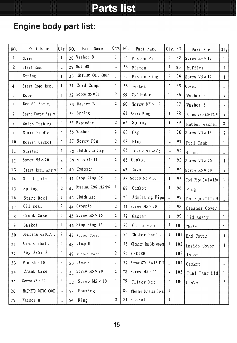
Parts list
91
Stop Switch
1 96
6X20cylinical pin
1 101
right handle
1
92
Le
handle
1
97
switch button
1 102
6X22 tapping screw
4
93
5
Xl4
tapping screw
2
98
Coil
spring
1 103
gasoline
engine
1
assembly
94
power wire
1 99
pressing board
1
95
protective sheath
1
100
4Xl4 tapping screw
2
13
l3
9
8
-

SERVICE
PLEASE READ THE FOLLOWING CAREFULLY
THE MANUFACTURER AND/OR DISTRIBUTOR HAS PROVIDED THE RTS LIST AND ASSEMBLY
DIAGRAM IN THIS MANUAL AS A REFERENCE TOOL ONLY. NEITHER THE MANUFACTURER OR
DISTRIBUTOR MAKES ANY REPRESENTATION OR WARRANTY OF ANY KIND TO THE BUYER THAT
HE OR SHE IS QUALIFIED TO MAKE ANY REIRS TO THE PRODUC OR THAT HE OR SHE IS
QUALIFIED TO REPLACE ANY PARTS OF THE PRODUC IN FACT, THE MANUFACTURER AND/OR
DISTRIBUTOR EXPRESSLY SES THAT ALL REPAIRS AND RTS REPLACEMENTS SHOULD BE
UNDERTAKEN BY CERTIFIED AND LICENSED TECHNICIANS,AND NOT BY THE BUYER. THE BUYER
ASSUMES ALL RISK AND LIABILITY ARISING OUT OF HIS OR HER REIRS TO THE ORIGINAL
PRODUCT OR REPLACEMENT RTS THERETO, OR ARISING OUT OF HIS OR HER INSTALLATION
OF REPLACEMENT PARTS THERETO.
Record Product's Serial Number Here: ________________ _
Note: If product has no serial number, record month and year of purchase instead.
Note: Some parts are listed and shown for illustration purposes only and are not available individually
as replacement pas.
A SAVE THESE INSTRUCTIONS.
Questions, problems, missing parts?
e tumi to ur retair,r ctal smer rce is reto h
ll U 98
Email Us: smetperuom
Hours of O
ration: m - (Mday - Friday)
PRODUCT MADE IN CHINA
16