
Installation Instruction
Version: 1.0
Dat
e: Jun. 2018
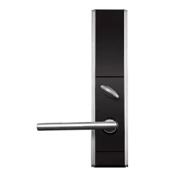
LH6500
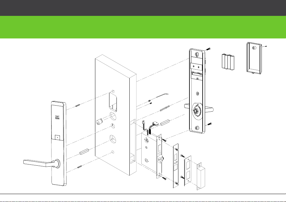
Lock Diagram
Before Installation
A
B
D
C
H
L
M
P
R
E
I
J
Q
N
O
F
1
K
G
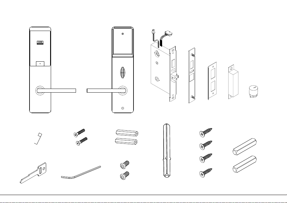
Packing List
2
A N
H J L M C
S
T
O
B
F E
G I D
3
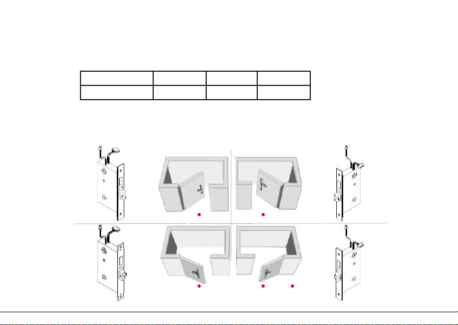
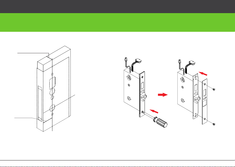
Door Preparation
1. Check door thickness; prepare proper screws and spindles.
Note: Please install the mortise (H) and strike plate (M) according to the above
H
H
H
H
Left inward Right inward
Left outward Right outward
2. Check the door’s open direction.
Door Thickness D Spindles G Spindle I Screws
40 - 50 mm 30 mm 75 mm 25 mm
Note: If the door is thicker than 40-50 mm,this lock shall not be applicable.
Standpoint

4
Cautions
1. New lock is defined as always open mode until it is locked once by mifare card.
2. Please swipe authorised card, time sync card, room card at first for the new lock.
3. The lock is equipped with mechanical keys for manual unlocking. Remove the
mechanical keys from the package and keep them in a safe place.
4. To power on the lock, four alkaline AA batteries (not included) are required.
Non-alkaline and rechargeable batteries ARE NOT RECOMMENDED.
5. Do not remove batteries when the lock is in working state.
6. When battery power is low, the lock will beep to remind user to renew the batteries.
Please do not mix up positive and negative while replacing battery.
7. Avoid contacting with corrosive substances, and do not hang objects on the handle.
8. The software within the lock manages the RFID cards, for more details refer to the
software user manual.
9. If there are any questions, please do not hesitate to contact the seller.
Installation
5
d
e
s
i
re
d h
an
dl
e
h
e
i
g
h
t
center line of
the handle
door
thick
ness
40~50 mm
backset
62.5 mm
2. Remove the mortise latch plate (J)
1. Drill holes on the door
Note 1: Align the template along the vertical
center line of the mortise (H) at the desired
handle height, and tape it to door.
Note 2: Mark the holes first, then start drilling.
H
K
J
6
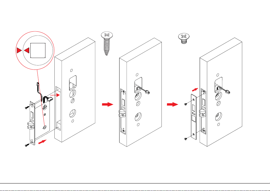
3. Install mortise (H)
I
I
H
K
J
K
7
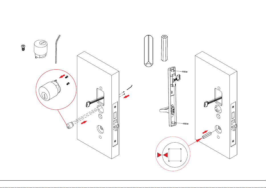
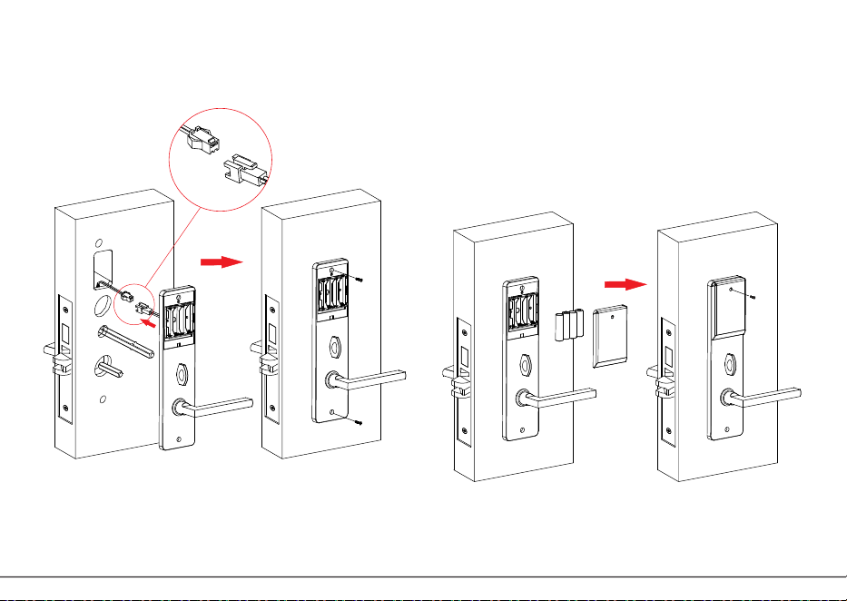
5. Install spindle (D) and stud (B)
D
4. Install lock cylinder (C)
F
C
E
Note: Ensure the two triangles are in horizontal alignment.
A
B
B
D
E
C
C
F
E
8
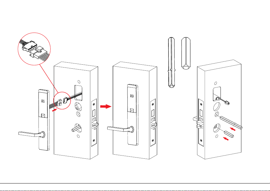
7. Install spindle (G) and (D)
D
G
6. Install outdoor unit (A)
A
G
D
9
9. Install the battery (P) and
battery cover (Q)
N
8. Install indoor unit (N)
P
O
Q
R
10
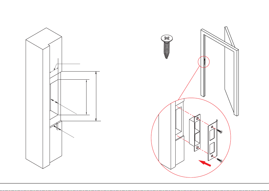
10. Mark and drill holes for strike
3 mm
22 mm
125 mm
89 mm
25 mm
I
M
L
I
11
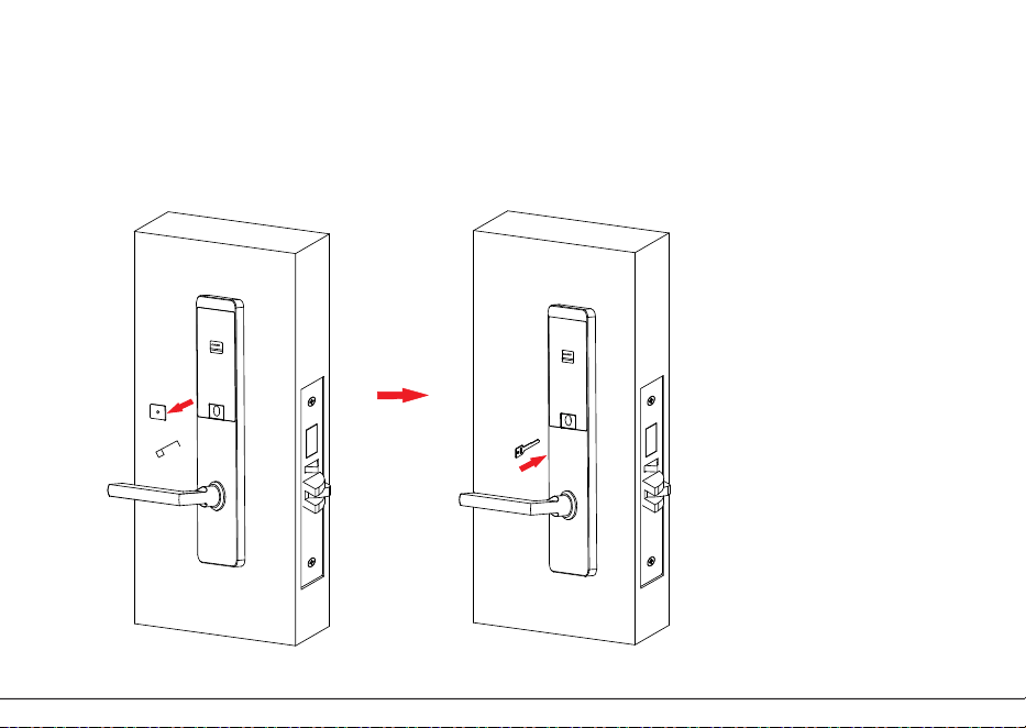
Step1: Remove the cover on the key hole with a hook (T ).
Step2: Insert mechanical key (S) into the key hole and rotate it at 90°.
11. Test Lock by mechanical key (S)
T
S

ZK Building, Wuhe Road, Gangtou,
Bantian, Buji Town, Longgang
District, Shenzhen China 518129
Tel: +86 755-89602345
Fax: +86 755-89602394
www.zkteco.com
© Copyright 2018. ZK TECO CO., LTD. ZKTeco Logo is a registered trademark of ZKTeco or a related company. All other product and company names mentioned are used for
identification purposes only and may be the trademarks of their respective owners. All specifications are subject to change without notice. All rights reser ved.


