
Installation Guide
Model: SL03-T4 Series
Due to regular upgrades of systems and products, ZKTeco could not guarantee exact consistency between
the actual product and the written information in this manual
Version: 1.1
English
.

1.
2.
3.
Table of Contents
4.
5.
6.
7.
1
Important Safety Instructions
Please read this Installation Guide carefully and contact the Customer Care for any
installation queries.
It is recommended that installation be carried out by a professional technician to
prevent any potential service charges that can occur due to incorrect installation.
Make sure the door surface is at to avoid false tamper alarm.
When the batteries are inserted in reverse positions, it may result in liquid leakage or
damage.
DO NOT leave all mechanical keys indoors. It is recommended that at least one key be
left in a safe place outside the home.
DO NOT attempt to disassemble or repair the device without authorization.
We regularly revise the contents of this Installation Guide and update our products
without prior notice to enhance quality and performance.
What's in Box...................................................................................................................2
Installation Diagram.......................................................................................................3
Installation Procedure....................................................................................................3
1. Check Door Properties..............................................................................................................................3
2. Drill Holes on the Door..............................................................................................................................5
3. Install the Mortise.......................................................................................................................................6
4. Install the Exterior Assembly..................................................................................................................6
5. the ..................................................................................................................7Install Interior Assembly
6. the the Battery .........................................................................................7Install Batteries and Cover
7. the the ........................................................................................................8Install Strike Plate and Box
8. ..................................................................................................................................................8Physical Test
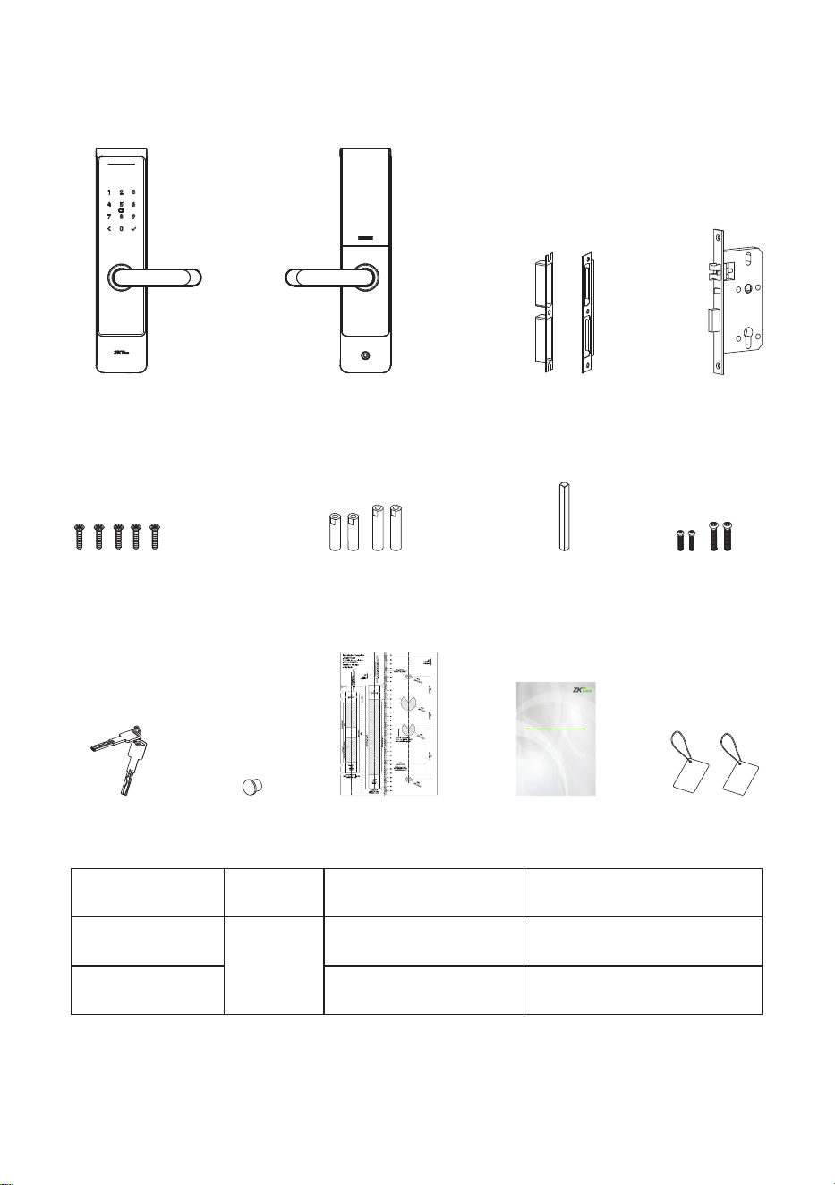
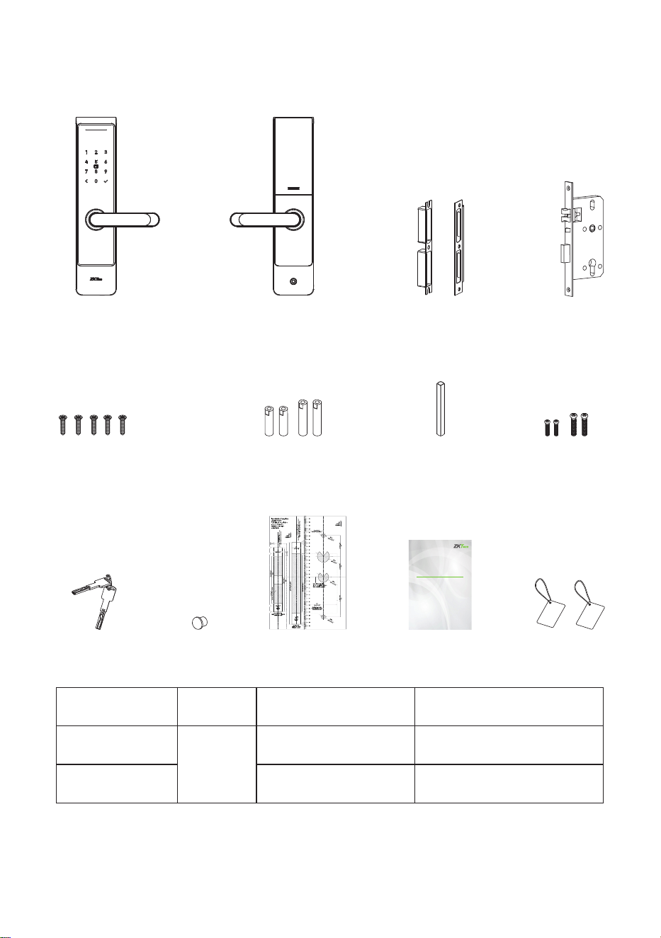
What's in Box
Note: Screws and Studs for the doors of thickness from 35 to 60 mm are included in the
standard package. Please use the appropriate set of accessories as per your door's
thickness to ensure the lock functions properly.
2
Door Thickness
35 to 46 mm
46 to 60 mm
Mounting Plate Studs
Spindle
70mm
Interior Assembly Screws
35mm
40mm
25mm
40mm
Strike Plate and Box
SpindleMounting Plate
Studs
Interior Assembly
Screws
IC Card *2Mechanical Key *2 Silicone Plug Installation Template Installation Guide
Mortise
Mortise Screws
Interior AssemblyExterior Assembly
Installation Guide
Model : SL03-T4 S eries
Version: 1.0
English
Due to regular upgrades of systems and products, ZKTeco could not guarantee exact consistency between
the actual product and the written information in this manual.
Installation Diagram
3
Installation Procedure
1.
Mortise Screws
Mechanical Key
Strike Plate
and Box
Mortise
Lever
Exterior Assembly
Mounting Plate
Studs
Spindle
Interior Assembly
Interior Assembly
Screws
Silicone Plug
Battery
Cover
Batteries
(not included)
Check Door Properties
Measure the Door Thickness
1.1
Measure the door thickness and select the proper length of studs and screws. For details,
please refer to the table in Page 2.
Check the Door Opening Direction
The position of the handle is determined by the opening direction of the door. Below is
the graphical representation of door opening direction in reference to your location
outside the room.
1.2

4
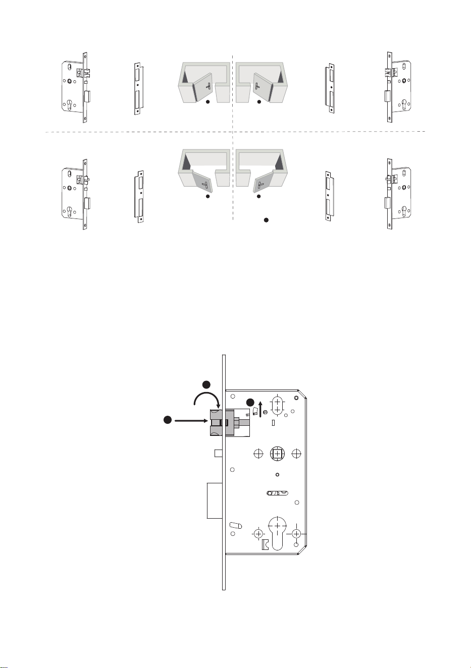
Push the reversing block in upward direction.
Push the latch bolt into the mortise.
Rotate the latch bolt at 180° inside the mortise, and then loosen it.
1.3
Adjust the Direction of the Latch Bolt (if needed)
1
2
3
180°
1)
2)
3)
Mortise
Strike Plate Strike Plate
Mortise
Mortise
Strike Plate
Strike Plate Mortise
Right Inward
Left Inward
Left Outward
Right Outward
User Location
5
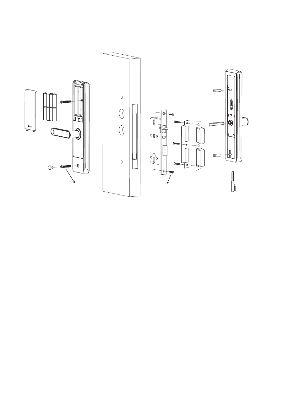
1.4
Use a screwdriver to remove the screw from the lever.
Rotate the lever 180° to the opposite direction.
Install and secure the lever with the screw.
1)
2)
3)
Change the Lever Direction (if needed)
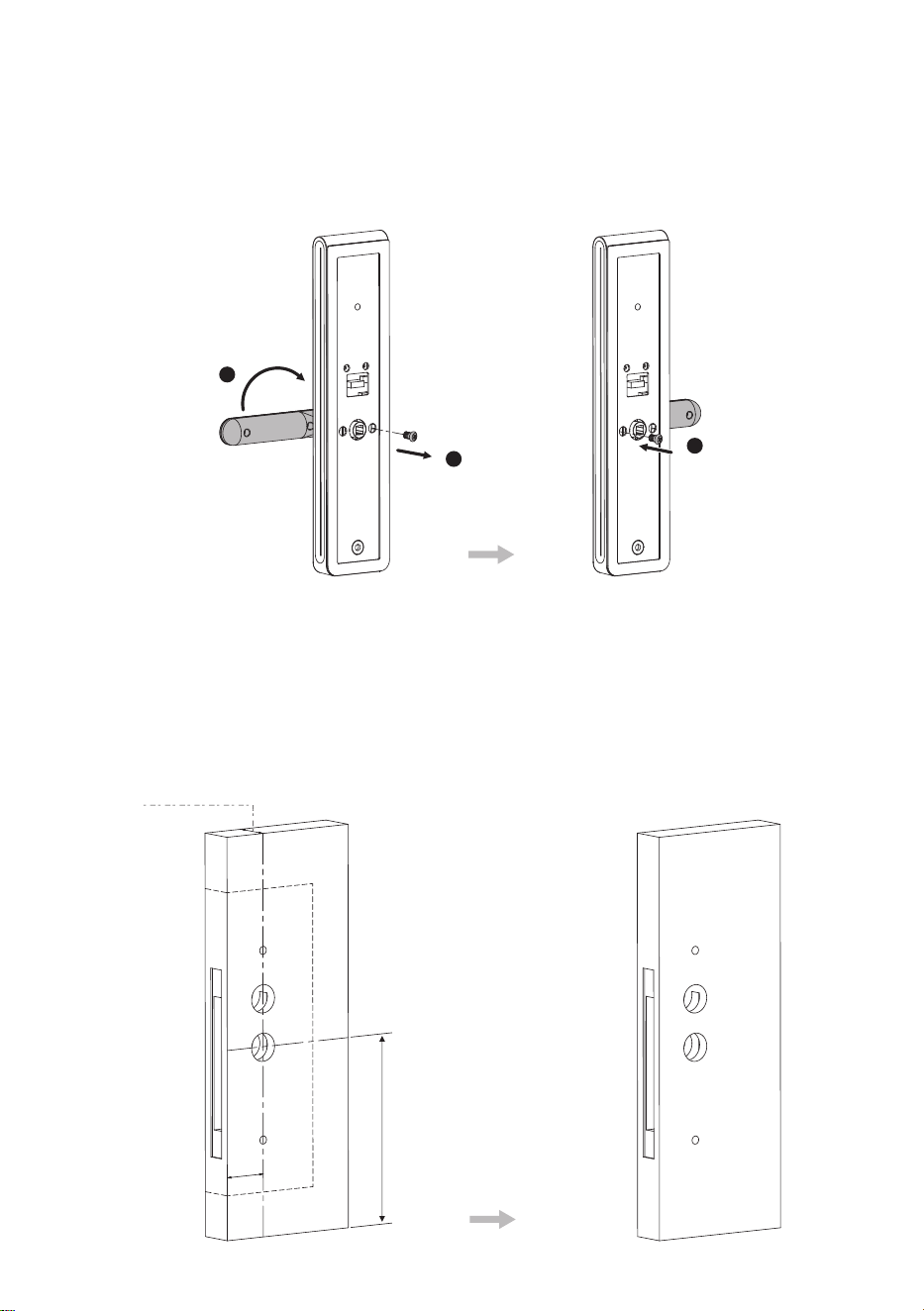
2.
Drill Holes on the Door
Align and tape the Installation Template at the desired lever height.
Mark for the holes to be drilled and drill the marked places.
1)
2)
1
2
3
Door
Th
i
c
kne
ss
35 to 60
m
m
Lever Centerline
Desired Lever Height
5
5
m
m
Back
s
et

Mounting Plate
Stud *2
Spindle *1
Mortise Screw *2
6
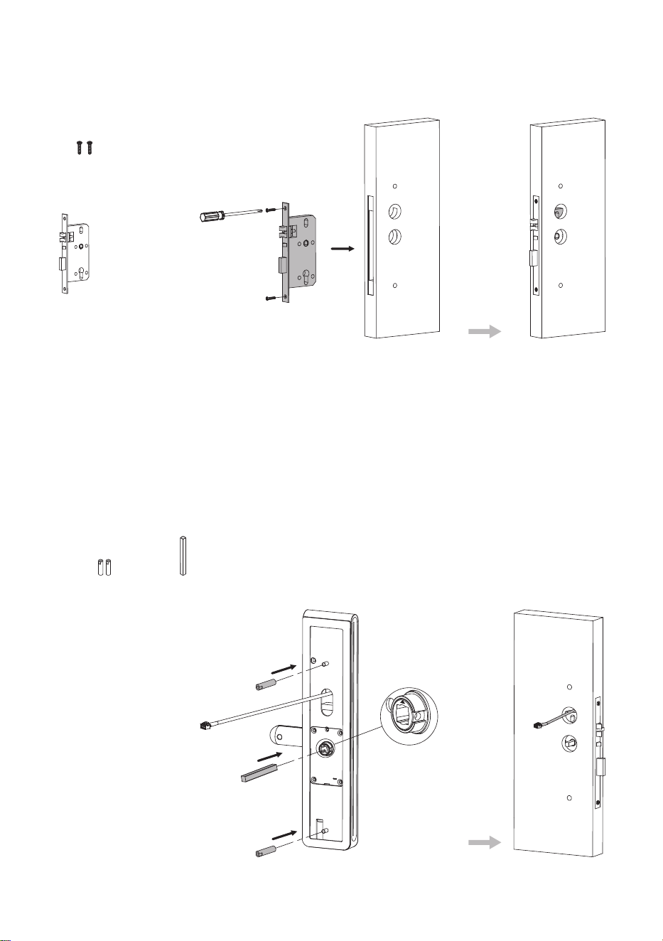
3.
Install the Mortise
Insert the Mortise into the door and secure it with the Mortise Screws.
4.
Install the Exterior Assembly
Install and secure the Mounting Plate Studs on the rear of the Exterior Assembly.
Insert the Spindle into the clutch, and make sure that the triangle mark is facing
upwards.
Insert the cable through the hole, and insert the Exterior Assembly into the
corresponding holes.
1)
2)
3)
Mortise
7
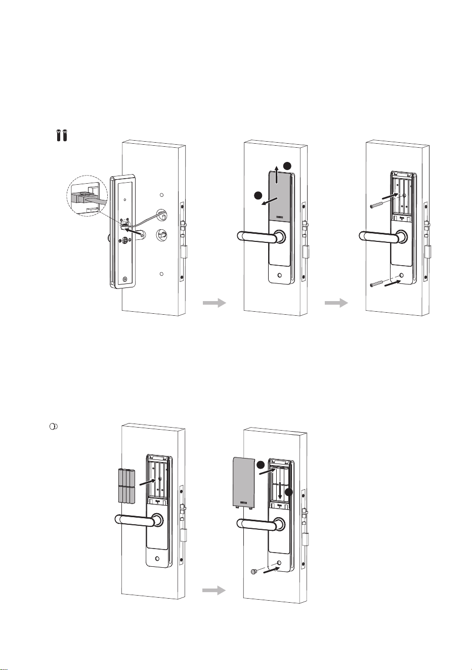
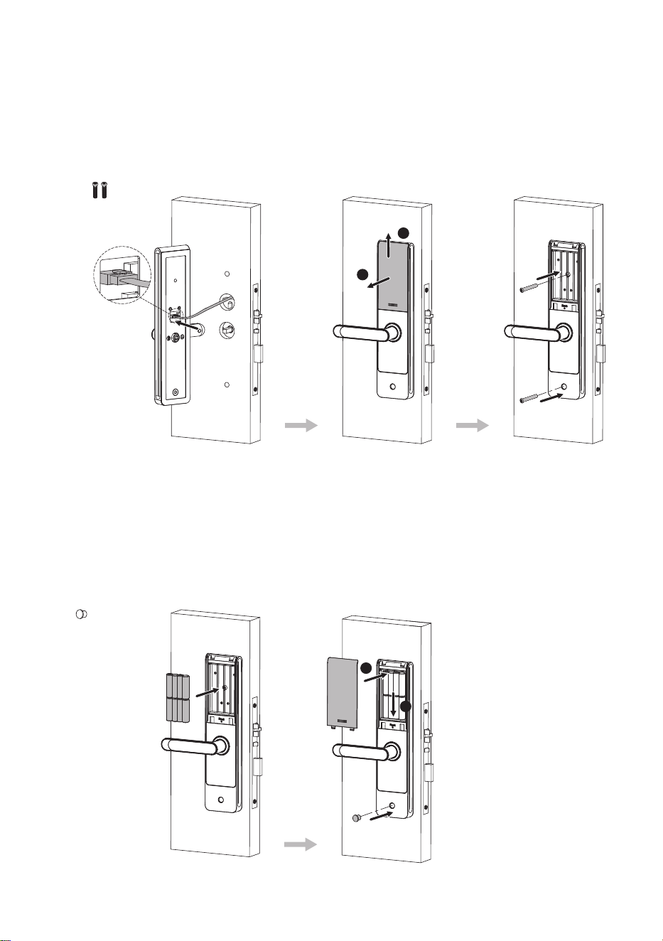
5.
Install the Interior Assembly
Connect the cable to the port on the Interior Assembly.
Pull the Battery Cover upwards, and then pull it out to remove from the interior lock.
Place the Interior Assembly properly on the door, and secure it with the Interior
Assembly Screws.
1)
2)
3)
Interior Assembly
Screw *2
1
2
6.
Install the Batteries and the Battery Cover
Insert eight alkaline AA batteries and cover them with a Battery Cover.
Use the Silicone Plug to cover the screw hole at the bottom of the Interior Assembly.
1)
2)
Silicone
Plug *1
1
2
8
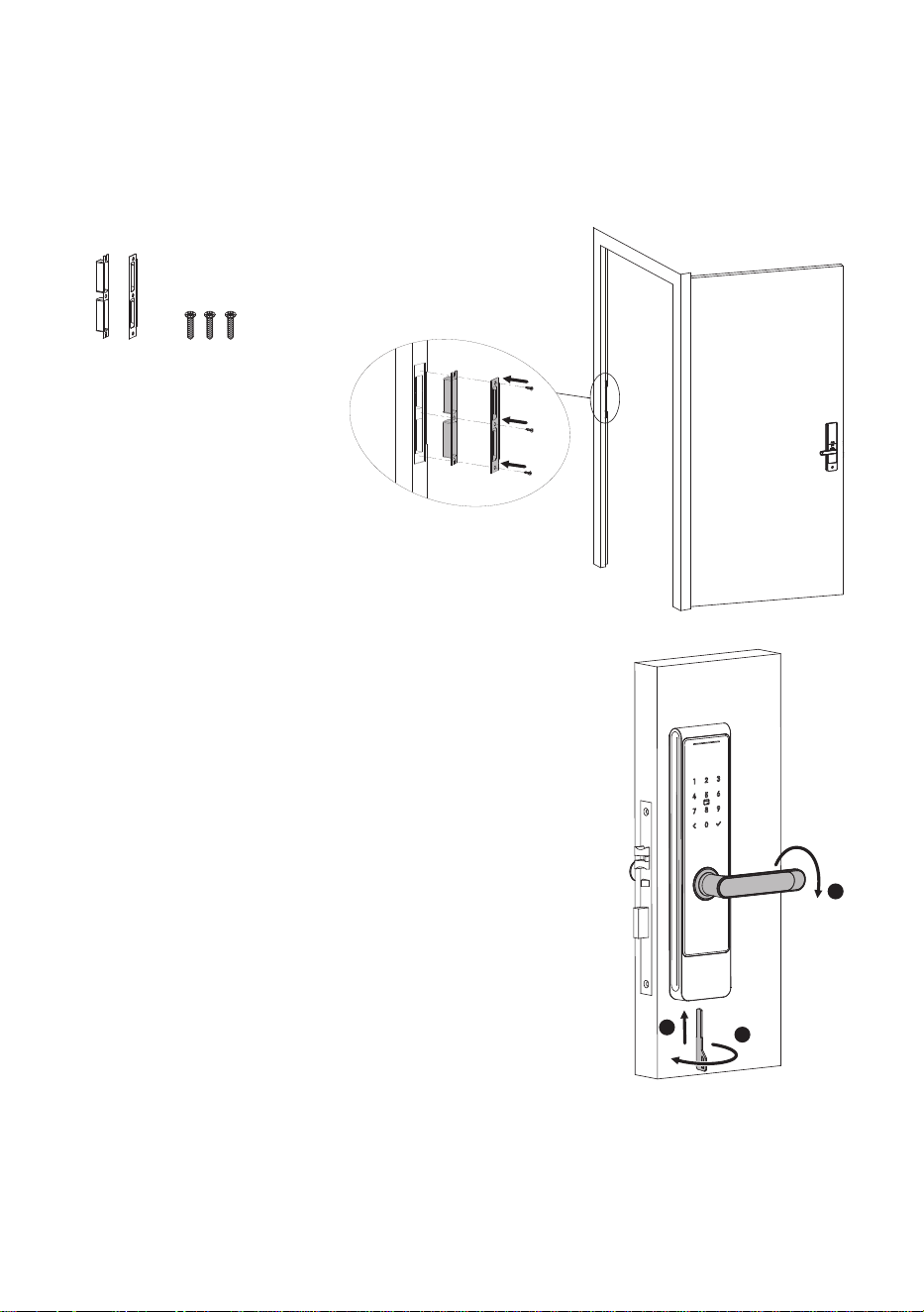
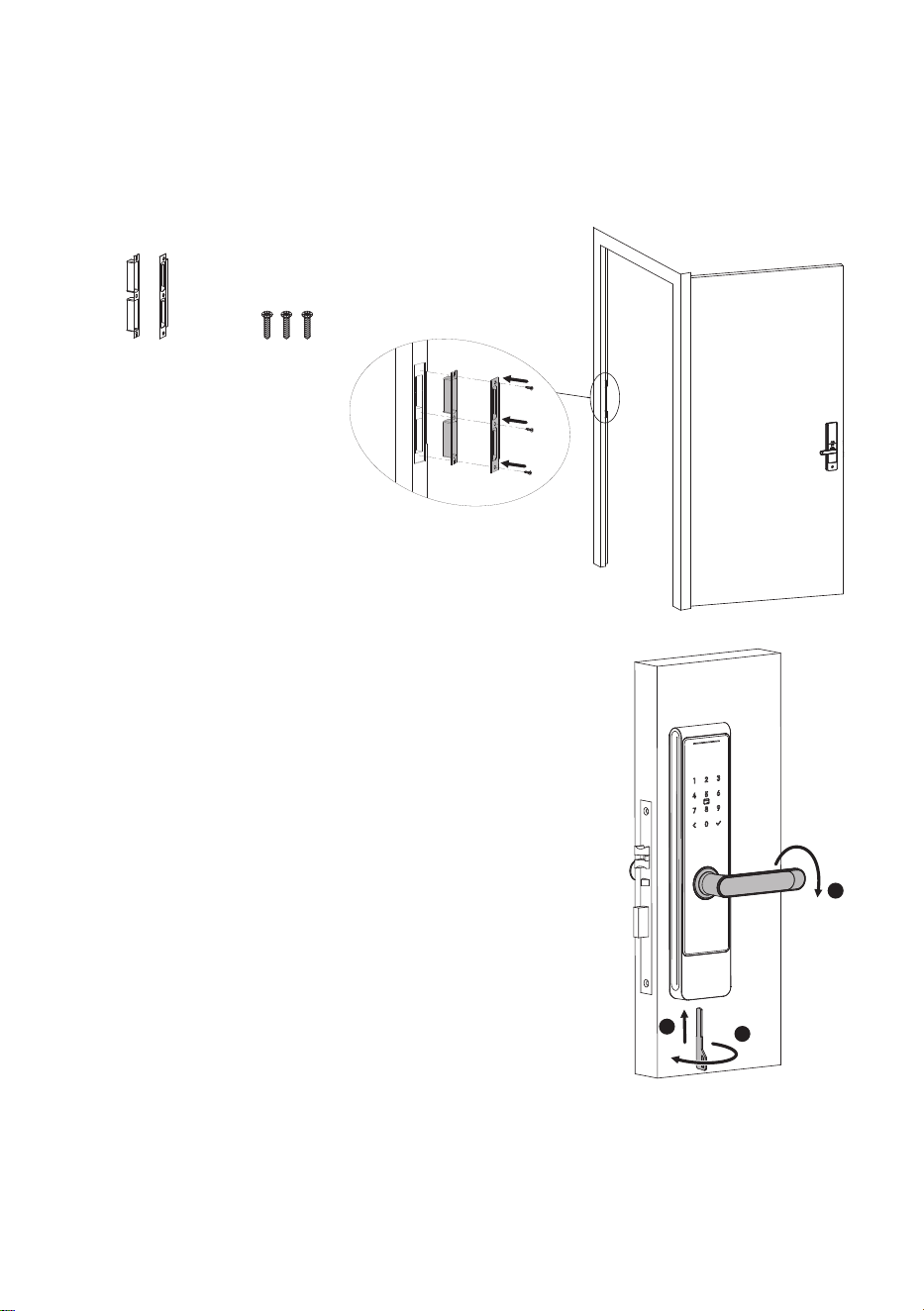
7.
Install the Strike Plate and the Box
Make sure that the Strike Box is aligned with the latch bolt. Then, use the Installation
Template to drill holes.
Align the Strike Plate and the Box with the drilled holes and secure them with
provided Mortise Screws.
1)
2)
Strike Plate
and Box *1
Screw *3
8.
Physical Test
8.1
Test Lever and Mortise
Lift up the exterior lever to extend the deadbolt of
the mortise.
Rotate down the exterior lever, and check whether
the latch bolt and dea dbolt re ma in lock ed
position.
Finally, rotate down the interior lever, and check
whether the latch bolt and deadbolt remain
retracted (unlocked) position.
1)
2)
3)
unlock the door.
8.2
Test Mechanical Key
Insert the Mechanical Key into the key hole and rotate
90°, then rotate the lever in downward direction to
3
1
2
8.3
Reset lock
Please remember the Administrator's Passcode in: Basic Management-->Basic Settings
-->Administrator Settings.
If the lock is bound to another system, you must enter the original system's 7-digit
passcode after holding the reset button to reset the lock. Forgetting the passcode
leaves no alternative reset method.

Guía de Instalación
Modelo: Series SL03-T4
Debido a las actualizaciones periódicas de los sistemas y productos, ZKTeco no puede garantizar quela
información escrita en este manual coincida exactamente con la del producto real
Versión: 1.1
Español
.

1.
2.
3.
4.
5.
6.
7.
1
Por favor lea la guía de Instalación cuidadosamente o contacte a atención a clientes
para cualquier consulta sobre la instalación.
Recomendamos encarecidamente la instalación profesional, para evitar cualquier
cargo adicional de servicio que pueda ocasionar la instalación incorrecta del producto.
Asegúrate de que la supercie de la puerta esté plana para evitar señales falsas de
alarma de anti-sabotaje.
Si se colocan las pilas al revés, puede provocar fugas de líquido o rupturas.
NO deje todas las llaves mecánicas dentro de la casa. Se recomienda que al menos
una llave se guarde en un lugar seguro fuera del hogar.
NO intente desinstalar o reparar el dispositivo sin autorización.
Se revisa constantemente el contenido de esta Guía de instalación y se hacen
cambios sin previo aviso, para mejorar el rendimiento de los productos.
Instrucciones de Seguridad Importantes
Tabla de Contenido
Contenido de la Caja.......................................................................................................2
Diagrama de Instalación................................................................................................3
Pasos de Instalación.......................................................................................................3
1. Comprobar las propiedades de la puerta...........................................................................................3
2. Taladrar Agujeros en la Puerta ...............................................................................................................5
3. Instalar la Mortaja.......................................................................................................................................6
4. Instalación de la Unidad Exterior...........................................................................................................6
5. Instalación de la Unidad Interior...........................................................................................................7
6. Instalación de la Batería y la Cubierta..................................................................................................7
7. Instalación de la Placa Metálica y la Caja.............................................................................................8
8. Prueba física.................................................................................................................................................8
Nota: Los tornillos y taquetes para las puertas de espesor de 35 a 60mm están incluidos en
el paquete estándar. Utilice el juego de tornillos adecuado según el grosor de su puerta,
para asegurar el correcto funcionamiento de la cerradura.
2
35 a 46 mm
46 a 60 mm
70mm
35mm
40mm
25mm
40mm
Contenido de la Caja
Grosor de
la Puerta
Perno
Taquetes de la
Placa de Montaje
Tornillos de
Unidad Interior
Tornillos de
Mortaja
Perno
Taquetes de la
Placa de Montaje
Tornillos de
Unidad Interior
Tarjetas IC *2
Llaves Mecánicas *2 Tapón de
Silicona
Plantilla de Instalación Guía de Instalación
Placa Metálica y Caja
Mortaja
Unidad InteriorUnidad Exterior
Guía de Instalación
Model o: Serie s SL03-T4
Versión: 1.0
Español
Debido a las actualizaciones periódicas de los sistemas y productos, ZKTeco no puede garantizar quela
información escrita en este manual coincida exactamente con la del producto real.

Diagrama de Instalación
3
1.
1.1
Mida el grosor de la puerta y seleccione el taquete y la longitud de tornillo adecuados.
Para más detalles, consulte el contenido de la tabla de la página 2.
La posición de la manija es determinada por la dirección de apertura de la puerta. Debajo
se encuentra la representación gráfica de la apertura de la puerta, referencia a su
ubicación fuera de la habitación.
1.2
Baterías
(no incluidas)
Cubierta de
la Batería
Manija
Llaves Mecánicas
Tapón de
Silicona
Unidad Interior
Unidad Exterior
Mortaja
Taquetes de la
Placa de Montaje
Tornillos de
Unidad Interior
Tornillos de
Mortaja
Perno
Pasos de Instalación
Comprobar las propiedades de la puerta
Verifique la dirección de apertura de la puerta
Placa Metálica
y Caja
Mida el grosor de la puerta
4
Empujar el bloque de inversión hacía arriba.
Empuje el pestillo hacia la mortaja.
Rotar el pestillo a 180° dentro de la mortaja y luego soltarlo.
1.3
1)
2)
3)
Ajuste la dirección del pestillo (Si es necesario)
1
2
3
180°
Mortaja
Mortaja
Mortaja
Mortaja
Placa Metálica
Placa MetálicaPlaca Metálica
Ubicación
del Usuario
Interior DerechaInterior Izquierda
Exterior Derecha
Exterior Izquierda
Placa Metálica

5
1.4
Utilice un desarmador para quitar el tornillo de la manilla.
Gire la manija a 180° hacia el lado opuesto.
Instale y asegure la manilla con el tornillo anterior.
1)
2)
3)
2.
Alinee y pegue la plantilla de instalación a la altura de manilla deseada.
Marcar los agujeros que se perforarán y perforar los lugares marcados.
1)
2)
1
2
3
55
mm
Cambie la dirección de la manija (si es necesario)
Taladrar Agujeros en la Puerta
L
ín
ea c
e
n
tr
a
l d
e la ma
n
illa
A
l
t
u
ra dese
ada de l
a m
ani
lla
Gro
so
r d
e p
u
e
r
ta
35 a 60
mm
F
o
ndo
6
3.
Inserte la mortaja en la puerta y asegúrela con los tornillos de mortaja.
Instalar la Mortaja
Mortaja
Tornillos de
Mortaja *2
4.
Instale y asegure los taquetes de la placa de montaje en la parte trasera del conjunto exterior.
Inserte el perno en el embrague. Asegúrese de que la marca del triángulo apunte
a la posición centrada verticalmente.
Enruta el cable a través del agujero e inserta el conjunto exterior en los agujeros
correspondientes.
1)
2)
3)
Instalación de la Unidad Exterior
Taquetes de la
Placa de Montaje *2
Perno *1
7
5.
Conecte el cable al puerto de la unidad interior.
Tire hacia arriba de la tapa de las pilas y luego sácala para removerla de la cerradura interior.
Coloque la unidad interior correctamente en la puerta, y fíjela con los tornillos de
unidad interior.
1)
2)
3)
1
2
6.
Inserte ocho pilas alcalinas AA y cúbralas con la tapa de la batería.
Utiliza el tapón de silicona para cubrir el agujero del tornillo en la parte inferior del
conjunto interior.
1)
2)
1
2
Instalación de la Unidad Interior
Tornillos de
Unidad Interior *2
Tapón de
Silicona *1
Instalación de la Batería y la Cubierta
8
7.
Asegúrese de que la caja esté en el mismo nivel que el pestillo y el cerrojo. Utilice la
plantilla de instalación para perforar orificios.
Alinee la placa metálica y la caja con los agujeros perforados y asegúrelos con los
tornillos de mortaja.
1)
2)
8.
Levante la manilla exterior para extender el cerrojo
de seguidad de la mortaja
Gire hacia abajo la manilla exterior y verifique si el
pestillo y el cerrojo de seguridad permanecen en
su posición bloqueada.
Por último, gire hacia abajo la manilla interior y
verifique si el pestillo y el cerrojo de seguridad
quedan retraídos (desbloqueados).
1)
2)
3)
3
1
Instalación de la Placa Metálica y la Caj
2
a
Placa Metálica
y Caja *1
Tornillos de
Mortaja *3
Prueba física
8.1
Prueba de manilla y Mortaja
8.2
Pruebe la cerradura usando la llave mecánica
Inserte la llave en el orificio de la llave y gire 90°, luego
gire la manija hacia abajo para abrir la puerta.
8.3
Restablecer la cerradura
Recuerde la contraseña del administrador en: Administración básica-->Configuración
básica-->Configuración del administrador.
Si su cerradura está vinculada a otro sistema, debe ingresar la contraseña de 7 dígitos
del sistema original después de mantener presionado el botón Reset para restablecerla.
Si olvidó la contraseña, no habrá otra manera de restablecer la cerradura.

ZKTeco Industrial Park, No. 32, Industrial Road,
Tangxia Town, Dongguan, China.
Phone : +86 769 - 82109991
Fax : +86 755 - 89602394
www.zkteco.com
Copyright © 2024 ZKTECO CO., LTD. All Rights Reserved.


