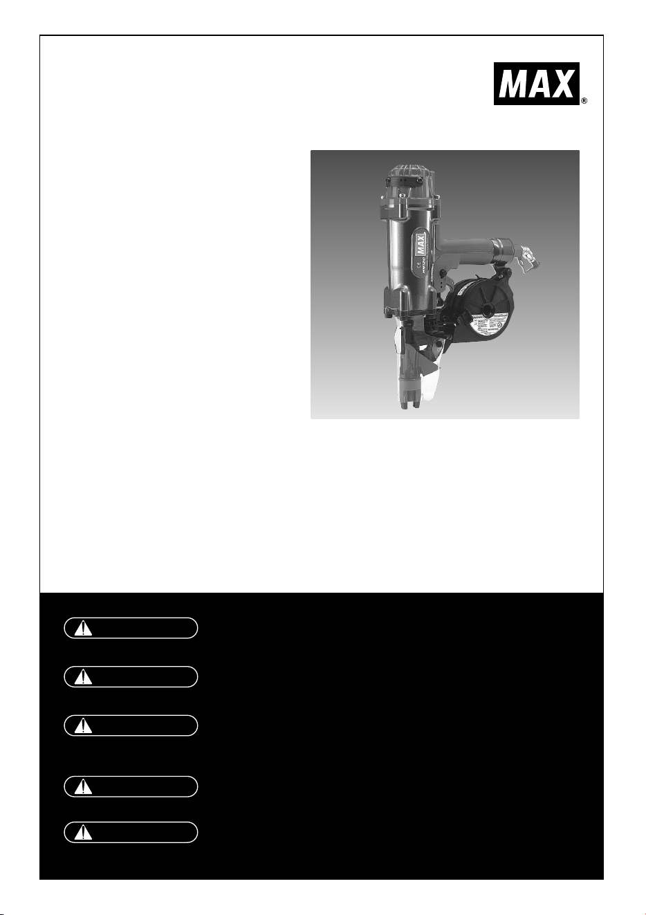
HN120
HIGH PRESSURE CONCRETE TOOL
HOCHDRUCK-BETONWERKZEUG
OUTIL POUR BÉTON À HAUTE
PRESSIONPRESSION
ATTREZZO PER CALCESTRUZZO AD
ALTA PRESSIONE
HERRAMIENTA PARA HORMIGÓN DE
ALTA PRESIÓN
OPERATING and MAINTENANCE MANUAL
BETRIEBSANLEITUNG
MANUEL D’UTILISATION et D’ENTRETIEN
MANUALE DI FUNZIONAMENTO E MANUTENZIONE
MANUAL DE OPERACIONES Y MANTENIMIENTO
BEFORE USING THIS TOOL, STUDY THIS MANUAL TO ENSURE SAFETY WARNING AND
INSTRUCTIONS.
KEEP THESE INSTRUCTIONS WITH THE TOOL FOR FUTURE REFERENCE.
LESEN SIE VOR INBETRIEBNAHME DES GERÄTES DIE GEBRAUCHS- UND SICHERHEITS-
HINWEISE. BITTE BEWAHREN SIE DIE GEBRAUCHS- UND SICHERHEITSHINWEISE AUF,
DAMIT SIE AUCH SPÄTER EINGESEHEN WERDEN KÖNNEN.
AVANT D’UTILISER CET OUTIL, LIRE CE MANUEL ET LES CONSIGNES DE SECURITE
AFIN DE GARANTIR UN FONCTIONNEMENT SUR.
CONSERVER CE MANUEL EN LIEU SUR AVEC L’OUTIL AFIN DE POUVOIR LE CONSULTER
ULTERIEUREMENT.
PRIMA DI USARE QUESTA MACCHINA, STUDIARE IL MANUALE PER PRENDERE ATTO
DEGLI AVVERTIMENTI E DELLE ISTRUZIONIPER LA SICUREZZA.
TENERE QUESTE ISTRUZIONI INSIEME ALLO STRUMENTO PER CONSULTAZIONI FUTURE
PARA EVITAR GRAVES DAÑOS PERSONALES O EN LA PROPIEDAD.
ANTES DE EMPLEAR LA HERRAMIENTA, LEER CON ATENCIÓN Y COMPRENDER LOS
SIGUIENTES INSTRUCCIONES DE SEGURIDAD.
WARNING:
ACHTUNG!
AVERTISSEMENT:
ATTENZIONE:
ATENCIÓN:

2
INDEX INHALTSVERZEICHNIS INDEX INDICE INDICE
ENGLISH Page 3 to 16 Page
DEUTSCH Page 17 to 30 Page
FRANÇAIS Page 31 to 44 Page
ITALIANO Page 45 to 58 Page
ESPAÑOL Page 59 to 72 Page
DEFINITIONS OF SIGNAL WORDS
WARNING: Indicates a potentially hazardous situation which, if not avoided, could result in death or serious injury.
CAUTION: Indicates a potentially hazardous situation which, if not avoided, may result in minor or moderate injury.
NOTE: Emphasizes essential information.
DEFINITIONEN DER HINWEISBEZEICHNUNGEN
ACHTUNG! Zeigt eine eventuell gefährliche Situation an, die den Tod oder schwere Verletzungen zur Folge haben
könnte, wenn sie nicht vermieden wird.
VORSICHT! Zeigt eine eventuell gefährliche Situation an, die leichte oder mittelschwere Verletzungen zur Folge
haben könnte, wenn sie nicht vermieden wird.
HINWEIS: Hebt wichtige Informationen hervor.
DÉFINITIONS DES DIFFÉRENTS DEGRÉS D’ AVERTISSEMENTS
AVERTISSEMENT Indique une situation éventuellement dangereuse qui, si elle n’est pas contournée, pourrait provoquer la
mort ou des blessure sérieuses.
ATTENTION Indique une situation éventuellement dangereuse qui, si elle n’est pas contournée, pourrait provoquer
des blessures légères à moyennement sérieuses.
REMARQUE Souligne des informations importantes.
DEFINIZIONE DELLE INDICAZIONI DI AVVERTIMENTO
ATTENZIONE: Indica l’eventualità che possa verificarsi una situazione pericolosa, la quale se non viene evitata, può
risultare letale o provocare gravi lesioni.
AVVERTENZA: Indica l’eventualità che possa verificarsi una situazione pericolosa, la quale se non viene evitata, può
provocare lesioni di lieve o media entità.
NOTA: Evidenzia informazioni importanti.
DEFINICIÓN DE LAS INDICACIONES DE ADVERTENCIA
¡
ATENCIÓN! Indica una situación potencialmente peligrosa que podría causar la muerte o graves lesiones si no se
evita.
¡
PRECAUCIÓN! Indica una situación potencialmente peligrosa que podría causar lesiones menos graves o leves si no
se evita.
NOTA: Resalta informaciones importantes.
3
ENGLISH
HN120
HIGH PRESSURE CONCRETE TOOL
INDEX
1. SAFETY INSTRUCTIONS
……………
4
2. SPECIFICATIONS &
TECHNICAL DATA
……………………
7
3. AIR SUPPLY AND CONNECTIONS
…
9
4.
INSTRUCTIONS FOR OPERATION
…
10
5. MAINTAIN FOR PERFORMANCE
…
16
6. STORING
……………………………
16
7. TROUBLESHOOTING/REPAIRS
……
16
OPERATING and MAINTENANCE MANUAL
BEFORE USING THIS TOOL, STUDY THIS MANUAL TO ENSURE SAFETY WARNING
AND INSTRUCTIONS.
KEEP THESE INSTRUCTIONS WITH THE TOOL FOR FUTURE REFERENCE.
WARNING:
4
1. SAFETY INSTRUCTIONS
PRECAUTIONS ON USING THE TOOL
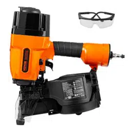
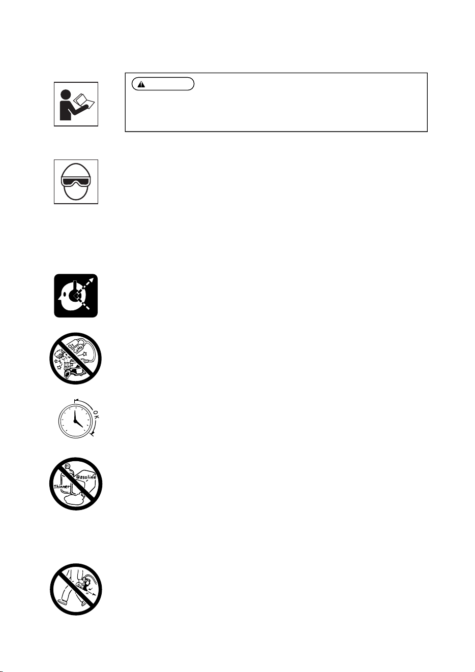
1. WEAR SAFETY GLASSES OR GOGGLES
Danger to the eyes always exists due to the possibility of dust being blown up by the exhausted air
or of a fastener flying up due to the improper handling of the tool. For these reasons, safety glasses
or goggles shall always be worn when operating the tool.
The employer and/or user must ensure that proper eye protection is worn. Eye protection equipment
must conform to the requirements of the American National Standards Institute, ANSI Z87.1 (Council
Directive 89/686/EEC of 21 DEC. 1989) and provide both frontal and side protection.
The employer is responsible to enforce the use of eye protection equipment by the tool operator
and all other personnel in the work area.
NOTE: Non-side shielded spectacles and face shields alone do not provide adequate protection.
2. EAR PROTECTION MAY BE REQUIRED IN SOME ENVIRONMENTS
As the working condition may include exposure to high noise levels which can lead to hearing
damage, the employer and user should ensure that any necessary hearing protection is provided and
used by the operator and others in the work area.
3. WHEN USING THE TOOL, BE SURE TO USE A SPECIAL AIR COMPRESSOR AND AIR HOSE
In order to improve its performance, it has set its working pressure higher than the conventional
nailers. To use the tool, you always need the special air compressor and air hose (MAX PowerLite
Compressor and MAX PowerLite Hose). Use of high-pressure gas (for example, oxygen, acetylene,
etc.) causes abnormal combustion, possibly resulting in explosion. Use only the special air
compressor and air hose.
4. OPERATE WITHIN THE PROPER AIR PRESSURE RANGE
The tool is designed to operate within an air pressure range of 210 to 320 p.s.i. (15 to 23 bar.)
The pressure should be adjusted to the type of the work being fastened. The tool shall never be
operated when the operating pressure exceeds 320 p.s.i. (23 bar.)
5. DO NOT OPERATE THE TOOL NEAR A FLAMMABLE SUBSTANCE
Never operate the tool near a flammable substance (e.g., thinner, gasoline, etc.). Volatile fumes from
these substances could be drawn into the compressor and compressed together with the air and this
could result in an explosion.
6. DO NOT USE A WRONG FITTINGS
The connector on the tool must not hold pressure when air supply is disconnected. If a wrong fitting
is used, the tool can remain charged with air after disconnecting and thus will be able to drive a
fastener even after the air line is disconnected, possibly causing injury.
7. DISCONNECT THE AIR SUPPLY AND EMPTY THE MAGAZINE WHEN THE TOOL IS NOT
IN USE
Always disconnect the air supply from the tool and empty the magazine when operation has been
completed or suspended, when unattended, moving to a different work area, adjusting,
disassembling, or repairing the tool, and when clearing a jammed fastener.
WARNING:
TO AVOID SEVERE PERSONAL INJURY OR PROPERTY DAMAGE
BEFORE USING THE TOOL, READ CAREFULLY AND UNDERSTAND THE FOLLOWING
“SAFETY INSTRUCTIONS”. FAILURE TO FOLLOW WARNINGS COULD RESULT IN DEATH OR
SERIOUS INJURY.
210psi
15bar
320psi
23bar
5
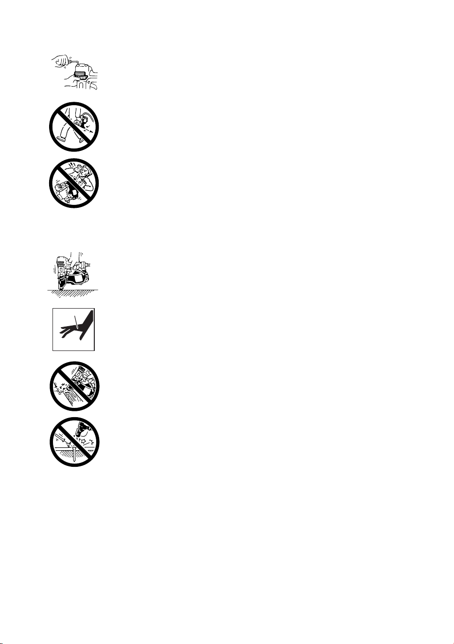
8. INSPECT SCREW TIGHTNESS
Loose or improperly installed screws or bolts cause accidents and tool damage when the tool is put
into operation. Inspect to confirm that all screws and bolts are tight and properly installed prior to
operating the tool.
9. DO NOT TOUCH THE TRIGGER UNLESS YOU INTEND TO DRIVE A FASTENER
Whenever the air supply is connected to the tool, never touch the trigger unless you intend to drive
a fastener into the work. It is dangerous to walk around carrying the tool with the trigger pulled, and
this and similar actions should be avoided.
10. NEVER POINT THE DISCHARGE OUTLET TOWARD YOURSELF AND OTHER PERSONNEL
If the discharge outlet is pointed toward people, serious accidents may be caused when misfiring.
Be sure the discharge outlet is not pointed toward people when connecting and disconnecting the
hose, loading and unloading the fasteners or similar operations.
11. USE SPECIFIED FASTENERS (SEE PAGE 7)
The use of fasteners other than specified fasteners will cause the tool malfunction. Be sure to use
only specified fasteners when operating the tool.
12. PLACE THE DISCHARGE OUTLET ON THE WORK SURFACE PROPERLY
Failure to place the discharge outlet of the nose in a proper manner can result in a fastener flying
up and is extremely dangerous.
13. KEEP HANDS AND BODY AWAY FROM THE DISCHARGE OUTLET
When loading and using the tool, never place a hand or any part of body in fastener discharge area
of the tool. It is very dangerous to hit the hands or body by mistake.
14. DO NOT DRIVE FASTENERS CLOSE TO THE EDGE AND CORNER OF THE WORK AND THIN
MATE RIAL
The workpiece is likely to split and the fastener could fly free and hit someone.
15. DO NOT DRIVE FASTENERS ON TOP OF OTHER FASTENERS
Driving fasteners of the top of other fasteners may cause deflection fasteners which could cause
injury.
16. REMOVING THE FASTENERS AFTER COMPLETING OPERATION
If fasteners are left in the magazine after the completion of operation, there is the danger of a serious
accident occurring prior to the resumption of operation, should the tool be handled carelessly, or
when connecting the air fitting. For this reason, always remove all fasteners remaining in the
magazine after completion of the operation.
17. CHECK OPERATION OF THE CONTACT TRIP MECHANISM FREQUENTLY IN CASE OF
USING A CONTACT TRIP TYPE TOOL
Do not use the tool if the trip is not working correctly as accidental driving of a fastener may result.
Do not interfere with the proper operation of the contact trip mechanism.
6
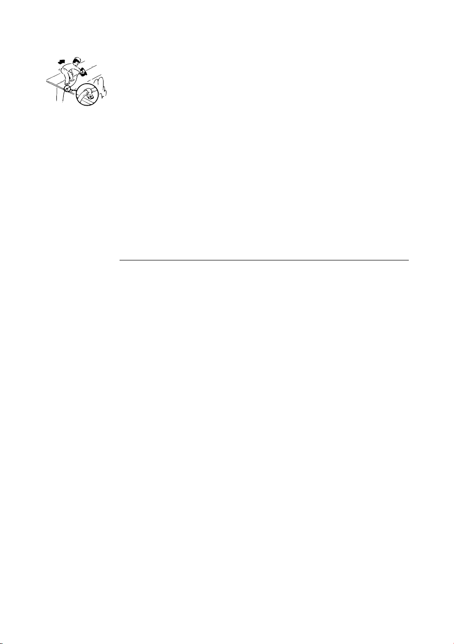
18. WHEN USING THE TOOL OUTSIDE OR ELEVATED PLACE
When fastening roofs or similar slanted surface, start fastening at the lower part and gradually work
your way up. Fastening backward is dangerous as you may loose your foot place.
Secure the hose at a point close to the area you are going to drive fasteners. Accidents may be
caused due to the hose being pulled inadvertently or getting caught.
19. NEVER USE THE TOOL IF ANY PORTION OF THE TOOL CONTROLS (e.g., TRIGGER, CONTACT
ARM) IS INOPERABLE, DISCONNECTED, ALTERED OR NOT WOKING PROPERLY
20. NEVER ACTUATE THE TOOL INTO FREE SPACE
This will avoid any hazard caused by free flying fasteners and excessive strain of the tool.
21. ALWAYS ASSUME THAT THE TOOL CONTAINS FASTENERS
22. RESPECT THE TOOL AS A WORKING IMPLEMENT
23. NO HORSEPLAY
24. NEVER LOAD THE TOOL WITH FASTENERS WHEN ANY ONE OF THE OPERATING CONTROLS
(e.g., TRIGGER, CONTACT ARM) IS ACTIVATED
OBSERVE THE FOLLOWING GENERAL CAUTION IN ADDITION TO
THE OTHER WARNINGS CONTAINED IN THIS MANUAL
•
Do not use the tool as a hammer.
•
Always carry the tool by the handle, never carry the tool by the air hose.
•
The tool must be used only for the purpose it was designed.
•
Never remove, tamper with the operating controls (e.g., TRIGGER, CONTACT ARM)
•
Keep the tool in a dry place out of reach of children when not in use.
•
Do not use the tool without Safety Warning label.
•
Do not modify the tool from original design or function without approval by MAX CO., LTD.
7
2. SPECIFICATIONS AND TECHNICAL DATA
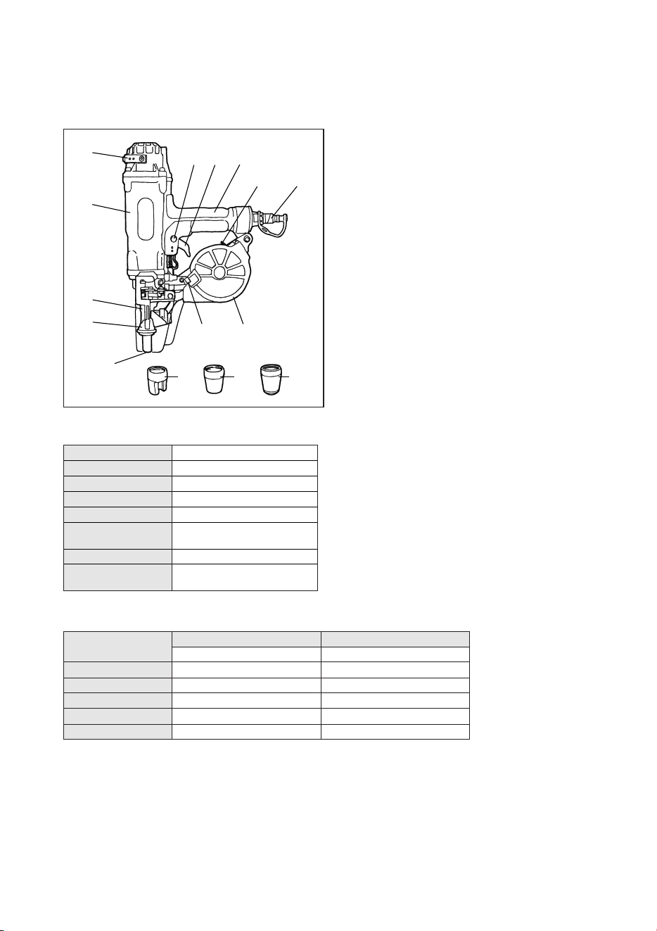
1. NAME OF PARTS
2. TOOL SPECIFICATIONS
PRODUCT NO. HN120
HEIGHT 15-3/4˝ (400 mm)
WIDTH 3-3/8˝ (85 mm)
LENGTH 12-3/8˝ (315 mm)
WEIGHT 6.4 lbs. (2.9 kg)
RECOMMENDED
210 to 320 p.s.i. (15 to 23 bar)
OPERATING PRESSURE
LOADING CAPACITY 50 Nails
AIR CONSUMPTION
4.7Rat 322 p.s.i. (23 bar)
operating pressure
q
!1
o
!2
w
r
t
e
i
!0
y u
!3
!4 !5
q
Exhaust Cover
w
Frame
e
Nose
r
Contact Arm
t
Discharge Outlet
y
Magazine Cap Lever
u
Magazine
i
Air Plug
o
Magazine Lock Lever
!0
Grip
!1
Trigger
!2
Trigger Lock Dial
!3
Attachment-A (Used for securing a thin steel plate to the
concrete)
!4
Attachment-B (Used for securing a wooden material to the
concrete or a thick steel plate)
!5
Attachment-C (Used for a light gage steel track to the
concrete)
3. FASTENER SPECIFICATIONS
NAIL LENGTH
PLASTIC SHEET COLLATED NAILS PLASTIC SHEET COLLATED PINS
1-1/4˝ to 2-1/2˝ (32 to 65 mm) 7/8˝ to 2˝ (22 to 52 mm)
SHANK DIAMETER
.113˝ to .148˝ (φ2.9 to φ3.8 mm) .148˝ (φ3.8 mm)
SHANK TYPE Smooth, Screw Smooth
HEAD DIAMETER
.256˝ to .303˝ (φ6.5 to φ7.7 mm) .283˝ to .315˝ (φ7.2 to φ8.0 mm)
HEAD THICKNESS
.039˝ to .059˝ (φ1.0 to φ1.5 mm) .079˝ (φ2.0 mm)
SHAPE OF THE POINT
DIAMOND POINT BARISTIC POINT
RECOMMENDED OPERATING PRESSURE:
210 to 320 p.s.i. (15 to 23 bar). Select the operating air pressure within this range for best fastener performance.
DO NOT EXCEED 320 p.s.i. (23 bar).

8
4. TECHNICAL DATA
q
NOISE
A-weighted single-event ------ LWA, 1s, d 110.0 dB
sound power level
A-weighted single-event ------ LpA, 1s, d 97.5 dB
emission sound pressure
level at work station
These values are determined and documented in accordance to EN12549 : 1999.
w
VIBRATION
Vibration characteristic value = 9.16 m/s
2
These values are determined and documented in accordance to ISO 8662-11.
This value is a tool-related characteristic value and does not represent the influence to the hand-arm-system when using the tool.
An influence to the hand-arm-system when using the tool will for example depend on the gripping force, the contact pressure
force, the working direction, the adjustment of mains supply, the workpiece, the workpiece support.
5. APPLICATIONS
*
Securing a thin steel plate to the concrete
*
Securing a wooden material to the concrete
*
Securing a wooden material to a thick steel plate
9
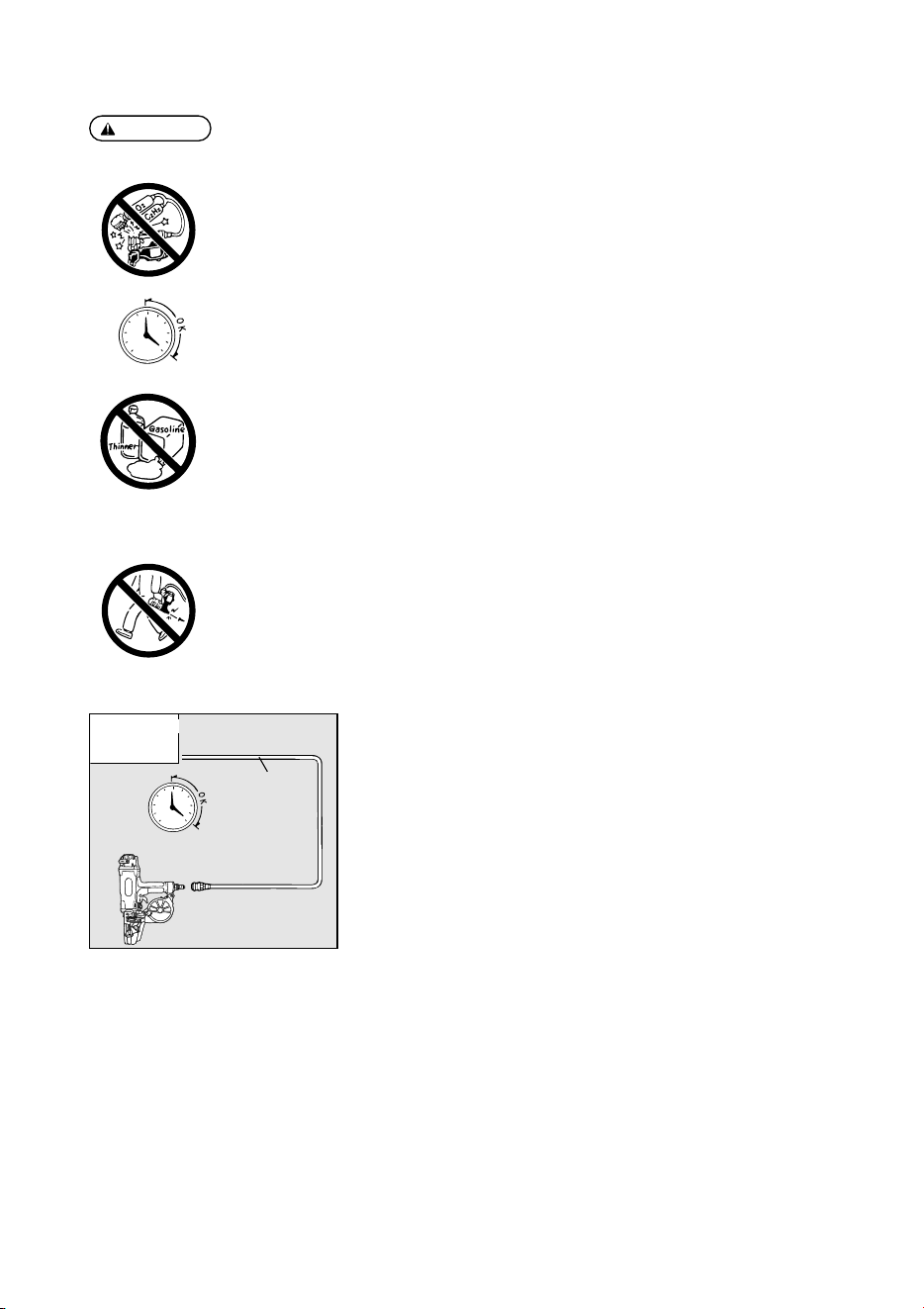
WHEN USING THE TOOL, BE SURE TO USE A SPECIAL AIR COMPRESSOR
AND AIR HOSE.
In order to improve its performance, it has set its working pressure higher than the
conventional nailers. To use the tool, you always need the special air compressor and
air hose (MAX PowerLite Compressor and MAX PowerLite Hose). Use of high-
pressure gas (for example, oxygen, acetylene, etc.) causes abnormal combustion,
possibly resulting in explosion. Use only the special air compressor and air hose.
NOTE:
Frequent, but not excessive, lubrication is required for the best performance. Oil added thru the air line
connection will lubricate the internal parts.
Air compressor
[
AIR COMPRESSOR / AIR HOSE
]
Used at 210 to 320 p.s.i. (15 to 23 bar)
210psi
15bar
320psi
23bar
Air hose
WARNING:
3. AIR SUPPLY AND CONNECTIONS
Read section titled “SAFETY INSTRUCTIONS”.
DO NOT USE ANY POWER SOURCE EXCEPT AN AIR COMPRESSOR
The tool is designed to operate on compressed air. Do not operate the tool on any other highpressure
gas, combustible gases (e.g., oxygen, acetylene, etc.) since there is the danger of an explosion. For this
reason, absolutely do not use anything other than an air compressor to operate the tool.
OPERATE WITHIN THE PROPER AIR PRESSURE RANGE
The tool is designed to operate within an air pressure range of 210 to 320 p.s.i. (15 to 23 bar.)
The pressure should be adjusted to the type of the work being fastened. The tool shall never be
operated when the operating pressure exceeds 320 p.s.i. (23 bar.)
DO NOT OPERATE THE TOOL NEAR A FLAMMABLE SUBSTANCE
Never operate the tool near a flammable substance (e.g., thinner, gasoline, etc.). Volatile fumes from
these substances could be drawn into the compressor and compressed together with the air and this
could result in an explosion.
DO NOT USE A WRONG FITTINGS
The connector on the tool must not hold pressure when air supply is disconnected. If a wrong fitting is
used, the tool can remain charged with air after disconnecting and thus will be able to drive a fastener
even after the air line is disconnected, possibly causing injury.
DISCONNECT THE AIR SUPPLY AND EMPTY THE MAGAZINE WHEN THE TOOL IS NOT IN USE
Always disconnect the air supply from the tool and empty the magazine when operation has been
completed or suspended, when unattended, moving to a different work area, adjusting, disassembling,
or repairing the tool, and when clearing a jammed fastener.
210psi
15bar
320psi
23bar
4. INSTRUCTIONS FOR OPERATION
Read section titled “SAFETY INSTRUCTIONS”.
1. BEFORE OPERATION
q
Wear Safety Glasses or Goggles.
w
Do not connect the air supply.
e
Inspect screw tightness.
r
Check operation of the contact arm & trigger if moving smoothly.
t
Connect the air supply.
y
Check the air-leakage. (The Tool must not have the air-leakage.)
u
Hold the Tool with finger-off the trigger, then push the contact arm against the work-piece. (The
tool must not operate.)
i
Hold the Tool with contact arm free from work-piece and pull the trigger. (The Tool must not
operate.)
o
Disconnect the air supply.
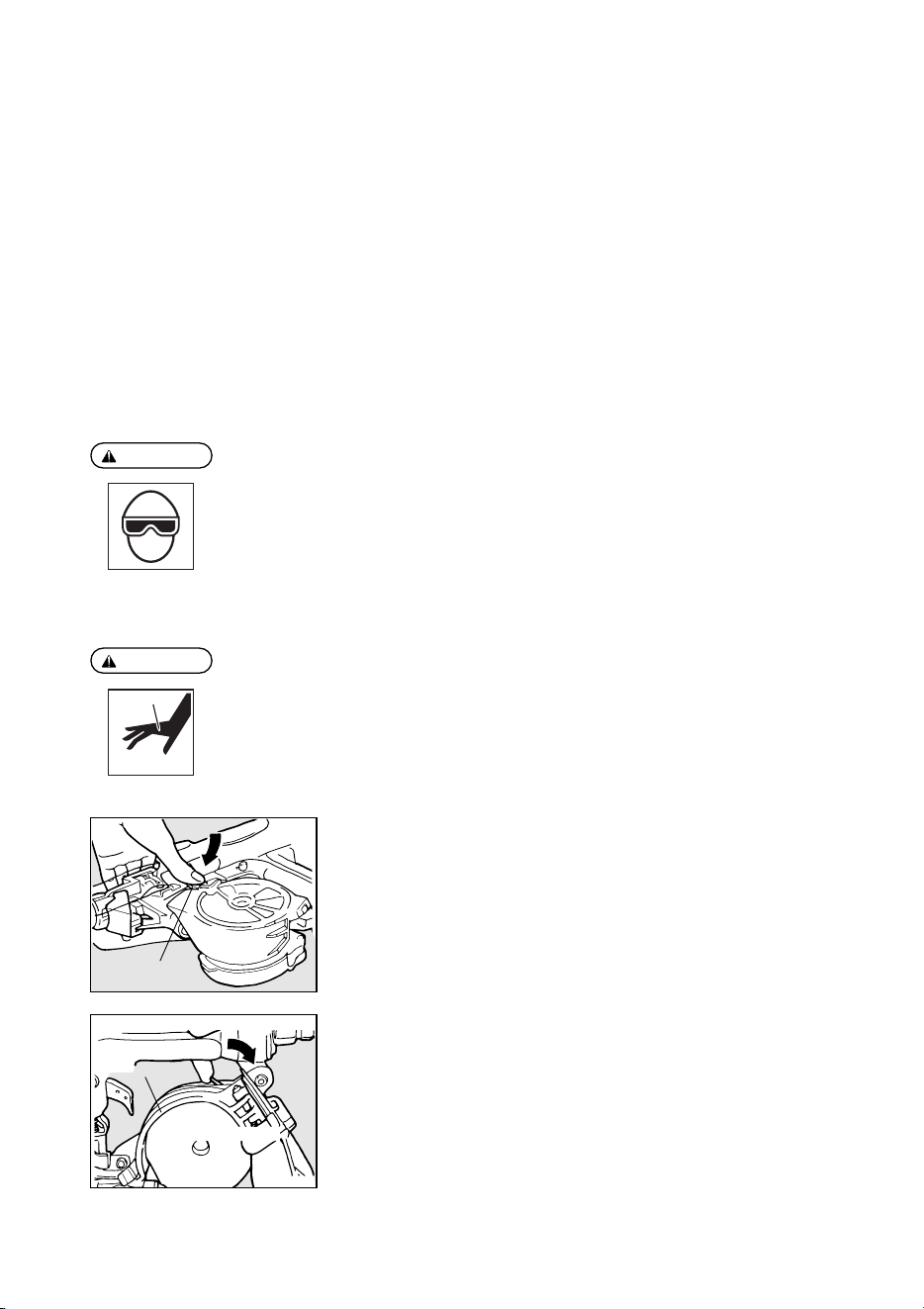
NAIL LOADING
q
Lock the trigger and disconnect the air hose.
w
Adjust the magazine direction in tune with the length of pins (or nails) used. First,
push the magazine cap lever to open the magazine cap.
e
Check adjustment:
Release the magazine lock lever to detach the magazine from the magazine hook,
and remove the magazine from the magazine holder.
Magazine cap lever
1. Release the magazine lock lever.
2. Pull out the magazine.
Magazine holder
WARNING:
WARNING:
2. OPERATION
Wear safety glasses or goggles danger to the eyes always exists due to the possibility of dust being
blown up by the exhausted air or of a fastener flying up due to the improper handling of the tool. For
these reasons, safety glasses or goggles shall always be worn when operating the tool.
The employer and/or user must ensure that proper eye protection is worn. Eye protection equipment
must conform to the requirements of the American National Standards Institute, ANSI Z87.1 (Council
Directive 89/686/EEC of 21 DEC. 1989) and provide both frontal and side protection.
The employer is responsible to enforce the use of eye protection equipment by the tool operator and all
other personnel in the work area.
NOTE: Non-side shielded spectacles and face shields alone do not provide adequate protection.
Keep hands and body away from the discharge outlet when driving the fasteners because of dangerous
of hitting the hands or body by mistake.
10
11
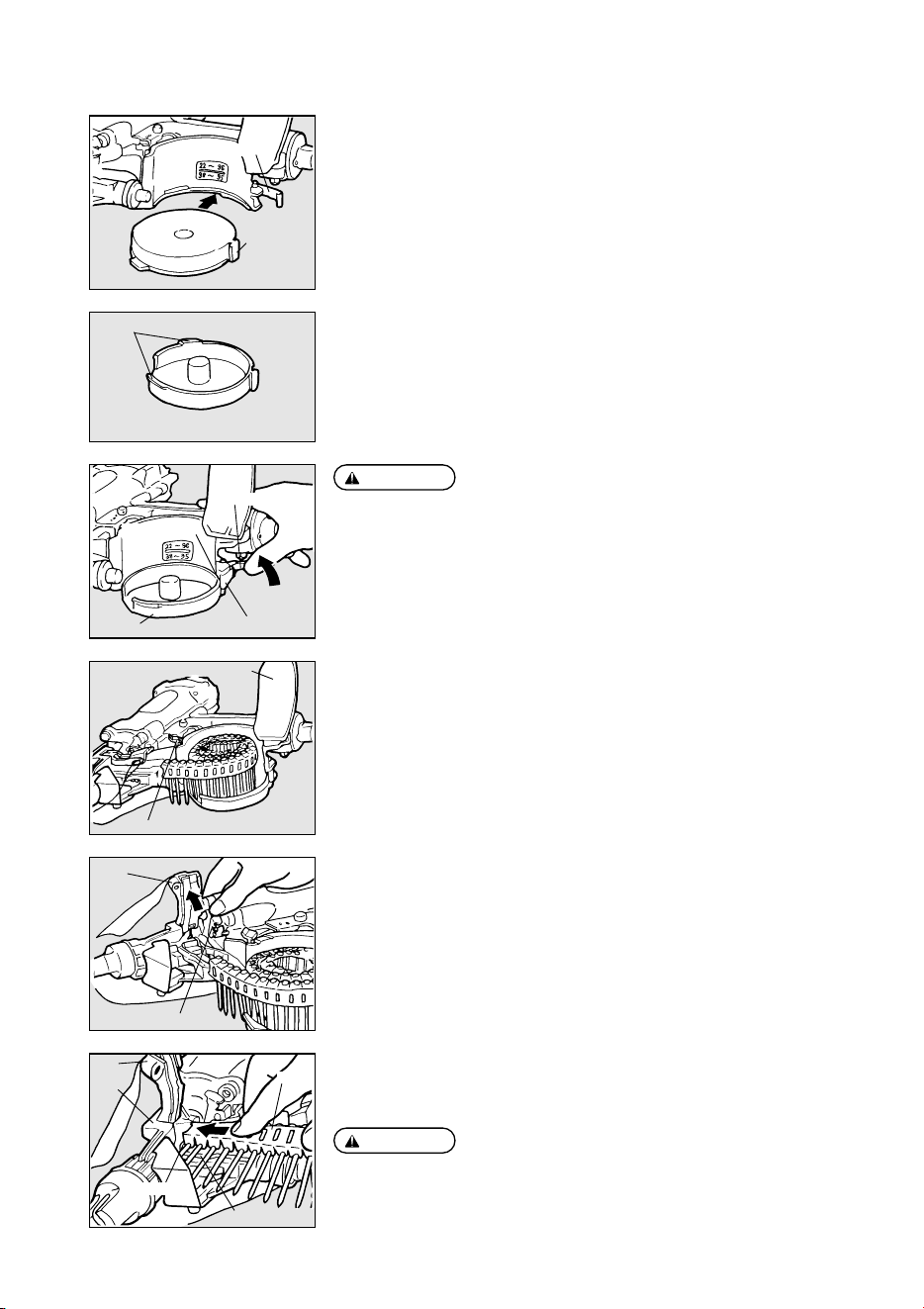
r
Determine the magazine direction in tune with the length of pins (or nails) used, fit
the magazine collar into the groove in the magazine holder, set the magazine hook
onto its mating part, and push the magazine lock lever to secure the magazine.
t
Push the magazine cap lever. With the magazine cap opened, set the pins (or nails)
and pull out the front end of the pin (or nail) coil.
y
Push the door lever to open the door.
u
Push in the pin (or nail) coil along the bridge until it has reached the end. Pushing it
in causes a feed pawl to swing away in between the first and second pins (or nails).
Stop pushing it there.
Magazine
Magazine hook
Hook mating
part
For 38 to 65 mm
For 22 to 32 mm
Hook mating part
Magazine
Magazine hook
Magazine lock lever
Magazine cap lever
Magazine cap
Door lever
Door
Nose
Coil
Feed pawl
Bridge
Door
●
At shipment, the magazine has been set in the direction for the pin/nail length
of 22 to 32 mm. When using 38 mm or longer pins/nails, set the magazine
reversely.
●
Be sure to set the magazine direction in tune with the length of pins (or nails)
used. If used in the inadequate direction, the pins (or nails) are not fed
properly.
CAUTION:
Confirm that the first pin (or nail) has been entirely set before the feed pawl (into
the nose).
CAUTION:
Collar
12
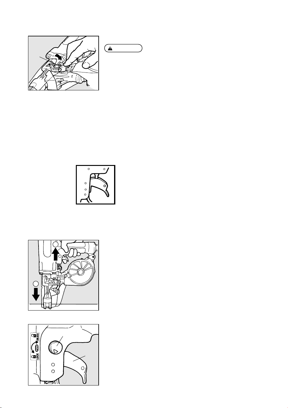
i
Push the door to close it.
o
Close the magazine cap.
!0
Connect the air chuck to the air plug. You are now ready to drive the pins (or nails).
Door
MODEL IDENTIFICATION
SEQUENTIAL TRIP
The Sequential Trip requires the operator to hold the tool against the work before pulling the trigger. This
makes accurate fastener placement easier, for instance on framing, toe nailing and crating applications.
The Sequential Trip allows exact fastener location without the possibility of driving a second fastener
on recoil, as described under “Contact Trip”.
The Sequential Trip Tool has a positive safety advantage because it will not accidentally drive a
fastener if the tool is contacted against the work-or anything else-while the operator is holding the
trigger pulled.
SEQUENTIAL TRIP
Identified by ORANGE TRIGGER.
2
1
PROCEDURE
q
Depress the contact arm.
w
Pull the trigger.
SINGLE FIRE OPERATION (SEQUENTIAL TRIP)
For single fire operation, depress the contact arm against the work surface and pull the trigger. Tool can
not fire a second nail until the trigger is released and tool can cycle.
TRIGGER LOCK MECHANISM
The tool is equipped with a trigger lock mechanism. Push and rotate the trigger LOCK
to the trigger UNLOCK position before driving nails.
Trigger lock dial
Trigger
Push the door firmly until the door lever has clicked.
CAUTION:
13
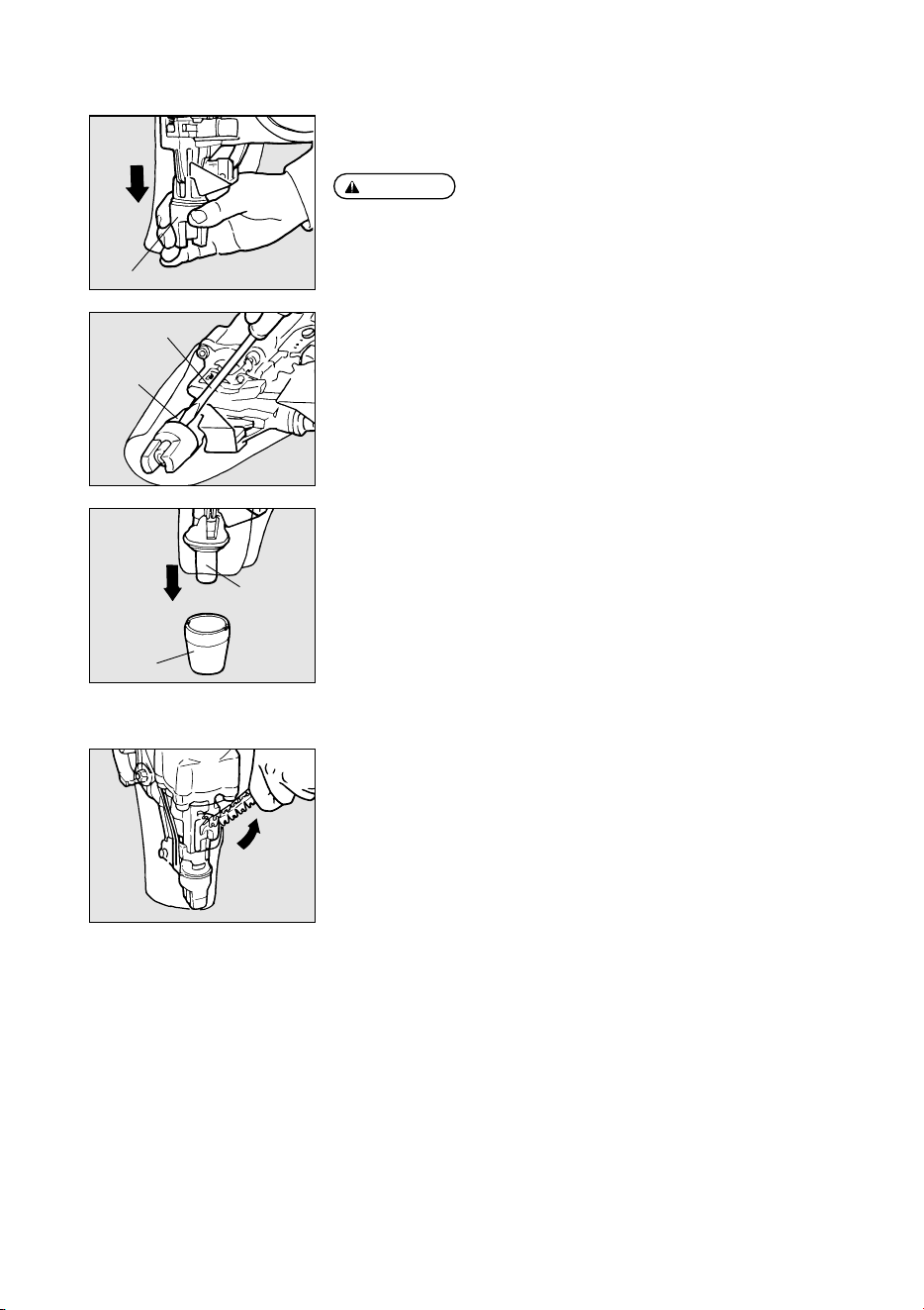
REPLACING THE ATTACHMENT
The machine comes with the attachments B and C as accessories. See the following for
the replacement method.
When replacing the attachment, be sure to lock a trigger and remove an air hose.
PROCEDURE
q
Remove the attachment A which has been attached at shipment; hold and draw it
out with your hand, while holding it.
Attachment A
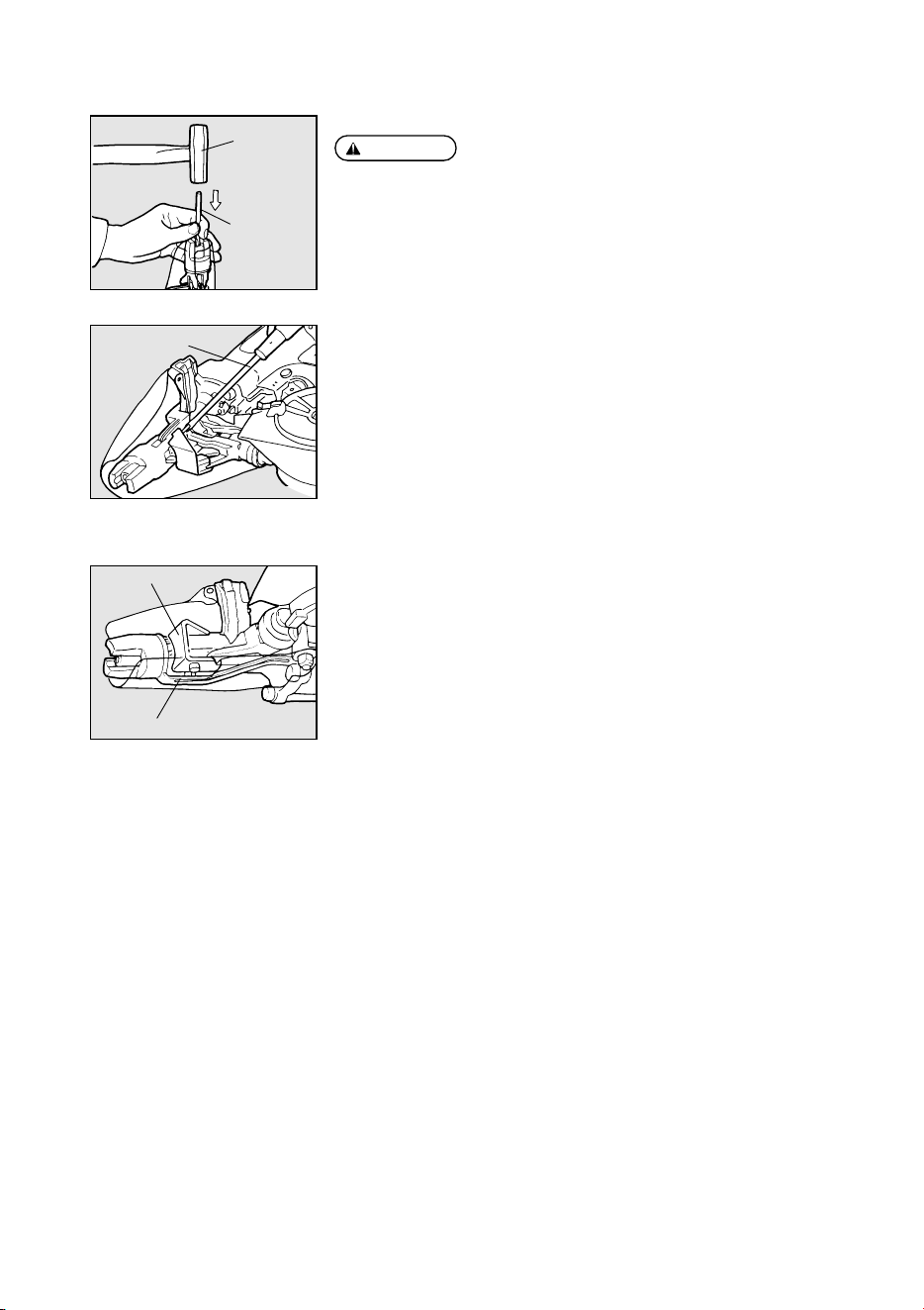
※
If it is not smoothly drawn out, insert a regular screwdriver, etc. into the clearance
between a contact arm and it, and squeeze it to remove.
Regular screwdriver
w
Put down the attachment B or C, insert the nose of the machine, and push it against
to attach.
Nose
HOW TO REMOVE PLASTIC SHEET
As nails are driven the plastic sheet will feed out of the tool. When sufficient strip has
been fed out it can be torn away by pulling against the tear edge in the nose.
Contact arm
Attachment B
WARNING:
14
Hammer
Punch
r
Remove the pins (or nails) jamming inside the nose, using the punch or a regular
screwdriver.
t
Set the pins (or nails) properly onto the feed pawl again and close the door.
Regular screwdriver
TROUBLESHOOTING
●
The Machine is not activated even if it is operated correctly.
When the pins (or nails) are not fed properly, a locking mechanism works to
deactivate the Machine. (Unless the feed pawl is completely OUT, it comes into
contact with a feed pawl retainer, disabling pin/nail driving work.)
If the feed pawl is not located appropriately, remove the pins (or nails) and set them
again.
●
No pin (or nail) is driven even if the Machine is operated correctly.
If the Machine is activated, but no pin (or nail) is actually driven, check the following:
q
Check whether or not the pins (or nails) have been set properly onto the feed pawl.
w
Check whether or not the pins (or nails) have come off the Plasticsheet.
※
If this is the case, cut off the empty Plasticsheet and set the pins (or nails) again.
e
Check whether or not the feed pawl and feed piston are being activated.
※
If not activated, apply 5 to 6 oil drips from the air plug.
Feed pawl retainer
This part comes into contact to lock.
HOW TO REMOVE JAMMING OF PINS/NAILS
When removing jamming of pins (or nails), be sure to lock the trigger prior to
disconnecting the air hose.
PROCEDURE
q
Lock the trigger and disconnect the air hose.
w
Remove the pins (or nails) out of the magazine.
e
Open the door, put a punch through the ejection port and hit it with a hammer.
WARNING:
15
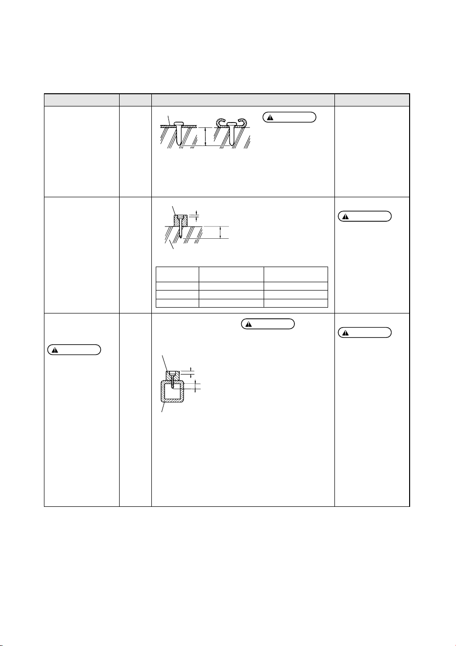
APPLICATIONS AND PINS/NAILS SELECTION CRITERIA
The Machine is applicable to the following purposes. When using it, select the pins/nails and leg length suitable for the driving
object.
Application Type Size (Leg Length) Attachment Used
Securing a thin steel plate
to the concrete
Ex.: Securing partition
tracks
Attachment-A,
Attachment-C
Plastic
Coil Pins
Select the pins so that a penetration
amount into the concrete will be 7/8” to 1”
(20 to 25mm).
Select the nails so
that a penetration
amount into the
concrete will be
5/8” to 1” (15 to
25mm).
Reference
Securing a wooden
material to the concrete
Ex.: Securing drum edges
Attachment-B
Use of the attachment-A
causes a nail sticking
out to the wooden
material.
Plastic
Coil Nails
Use of nails to secure
the thin steel plate to the
concrete causes them to
recoil or bend,
endangering you. Be
sure to use pins to
secure it to the concrete.
CAUTION:
●
Drivable steel plate thickness
is 1/8” to 11/64” (3.2 to 4.5
mm). Use the Machine only
within these limits.
●
Overdriving into the steel
plate reduces a holding force
extremely and deteriorates
durability of the Machine.
When working, check the
driving condition fully to
adjust the pressure.
●
Never drive the nails directly
into the thick steel plate,
because they may recoil or
bend, endangering you.
●
Be sure to apply the nose of
the ejection port to the object
at a right angle.
●
Do not use the Machine for
the roof or ceiling.
CAUTION:
CAUTION:
Securing a wooden
material to a thick steel
plate
When using, allow for
the nature of the driving
object and the
conditions at the work
site to comply with the
Work Standards.
Attachment-B
Use of the attachment-A
causes a nail sticking
out to the wooden
material.
Plastic
Coil Nails
(For Steel
Plate)
CAUTION:
CAUTION:
Thin Steel Plate
Penetration Amount into
Concrete
Penetration Amount
into Concrete
Wooden Material
Concrete
Select the nails so that a
penetration amount into the thick
steel plate will be 3/8” (10 mm)
or more.
Wooden Material
Sinks 1/16” to 3/16”
(2 to 5 mm)
Penetration
Amount
Thick Steel Plate
Sinks 1/16” to 3/16” (2 to 5 mm)
Wooden Material
Thickness
1-1/8” (27mm) 1-1/2” (38mm)
Approx. 1/2” to 5/8” (13 to 16 mm)
1-3/16” (30mm) 1-3/4” (45mm)
Approx. 5/8” to 7/8” (17 to 20 mm)
1-3/4” (45mm) 2-3/8” (60mm)
Approx. 5/8” to 7/8” (17 to 20 mm)
Nail Length Selected
Penetration Amount into
Concrete

16
5. MAINTAIN FOR PERFORMANCE
q
DO NOT FIRE THE NAILER WHEN IT IS EMPTY
w
USE RECOMMENDED OIL
The velocite or turbine oil should be used to lubricate the tool. Upon completion of operations, place 2
or 3 drops of oil into the air plug inlet with the jet oiler. (Recommended Oil : ISO VG32)
e
INSPECT AND MAINTAIN DAILY OR BEFORE OPERATION
Disconnect air supply and empty the magazine when inspecting or maintaining the tool.
(1) Drain air line filter and compressor
(2) Keep lubricator filled in air 3-pieces set
(3) Clean filter element of air 3-pieces set
(4) Tighten all screws
(5) Keep contact arm moving smoothly
6. STORING
q
When not in use for an extended period, apply a thin coat of the lubricant to the steel parts to avoid
rust.
w
Do not store the tool in a cold weather environment. Keep the tool in a warm area.
e
When not in use, the tool should be stored in a warm and dry place. Keep out of reach of children.
r
All quality tools will eventually require servicing or replacement of parts because of wear from the
normal use.
7. TROUBLE SHOOTING/REPAIRS
The troubleshooting and/or repairs shall be carried out only by the MAX CO., LTD.authorised distributors
or by other specialists.
WARNING: