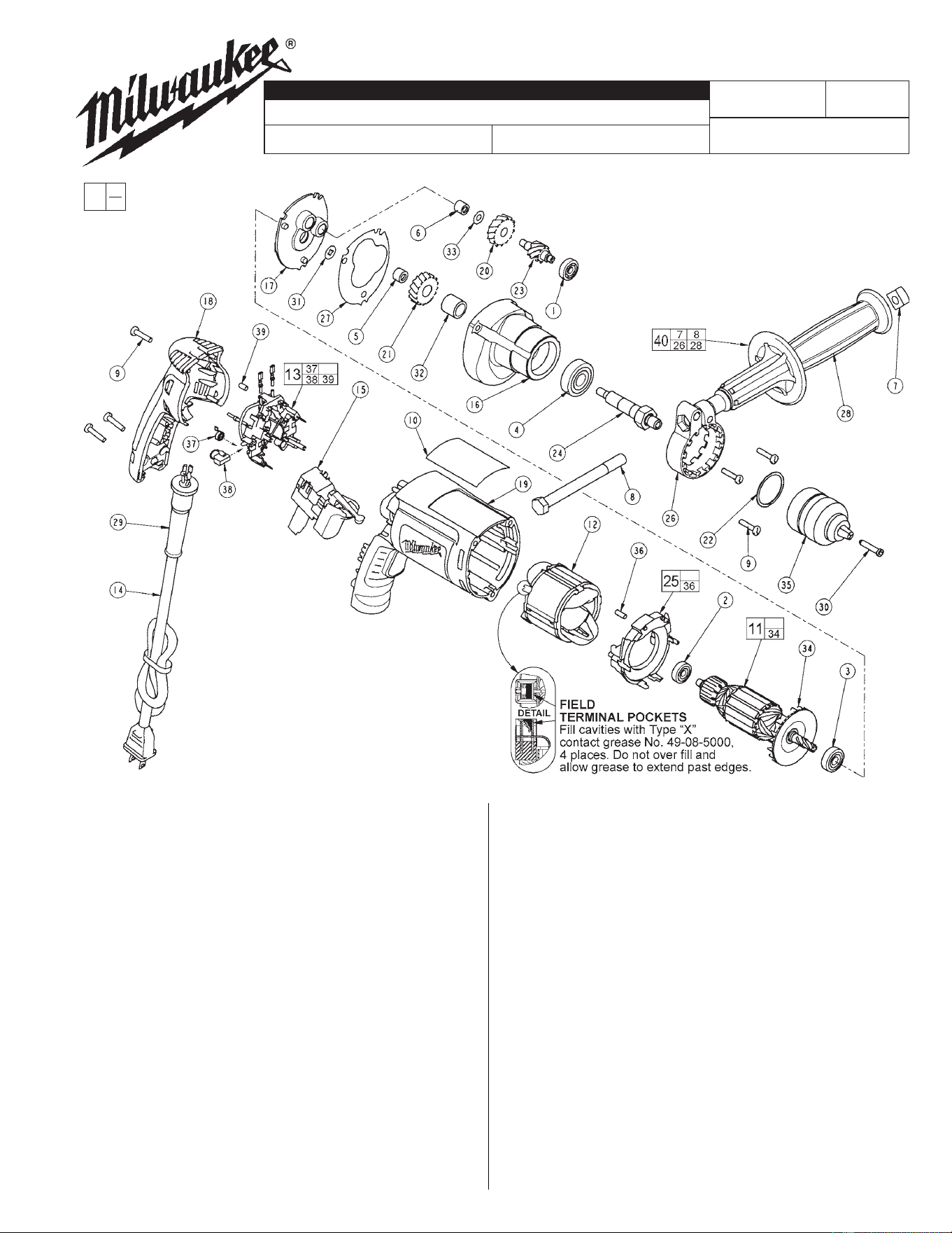
FIG. PART NO. DESCRIPTION OF PART NO. REQ.
1 02-04-0640 Ball Bearing (1)
2 02-04-0645 Ball Bearing (1)
3 02-04-0852 Ball Bearing (1)
4 02-04-1229 Ball Bearing (1)
5 02-50-1611 Needle Bearing (1)
6 02-50-2400 Needle Bearing (1)
7 06-54-0325 3/8-16 Square Nut (1)
8 06-75-2850 3/8-16 x 5-1/2 Hex Cap Screw (1)
9 06-82-7275 7-18 x 3/4 Slotted Plastite T-20 (6)
10 12-99-2665 Service Nameplate (1)
11 16-10-2215 Armature (1)
12 18-07-2200 Field (1)
13 22-18-1210 Brush Card Assembly (1)
14 22-64-6510 Cord Assembly (1)
15 23-66-2585 Switch (1)
16 28-14-2390 Gearcase (1)
17 28-28-2320 Diaphragm (1)
18 31-15-2010 Handle Halve (1)
19 31-50-2050 Motor Housing (1)
20 32-40-0100 Intermediate Gear (1)
21 32-75-0115 Spindle Gear (1)
22 34-80-2300 Retaining Ring (1)
23 36-66-0125 Intermediate Shaft (1)
24 38-50-5750 Spindle (1)
25 42-14-0460 Baffle Assembly (1)
WIRING INSTRUCTION
REVISED BULLETIN DATE
SERVICE PARTS LIST
MILWAUKEE ELECTRIC TOOL CORPORATION
13135 W. LISBON RD., BROOKFIELD, WI 53005
Drwg. 4
BULLETIN NO.
STARTING
SERIAL NO.
54-06-2875
58-01-1805
SPECIFY CATALOG NO. AND SERIAL NO. WHEN ORDERING PARTS
0201-20
CATALOG NO.
3/8 INCH DRILL
Jan. 2003
067A
00
0
EXAMPLE:
Component Parts
(Small #) Are
Included When
Ordering The
Assembly
(Large #).
FIG. PART NO. DESCRIPTION OF PART NO. REQ.
26 42-68-0800 Side Handle Clamp (1)
27 43-44-0985 Gasket (1)
28 43-62-0845 Side Handle (1)
29 44-76-0210 Cord Protector (1)
30 45-04-0750 Chuck Screw (1)
32 45-36-1095 Spindle Spacer (1)
33 45-88-7990 Thrust Washer (1)
34 22-84-0845 Fan (1)
35 48-66-1530 3/8 Two Sleeve Keyless Chuck (1)
36 45-30-0030 Slug (2)
37 23-52-1610 Brush Spring (2)
38 22-18-1310 Brush Assembly (2)
39 45-30-0035 Slug (1)
40 49-15-0265 Side Handle Assembly (1)
FIG. NOTES:
4,21 Support the output ball bearing inside the gearcase before
pressing off the spindle gear.
5,6 Needle bearings to be pressed flush to .010 under flush
from the end which has the vendors identification.
Cat. No. 31-53-0205
Lock Button Plug
LUBRICATION (Type "Y" Grease, No. 49-08-5270)
• Place 5 gm. (.02 oz.) of grease on top of the inserted intermediate ball
bearing (1) and on the intermediate pinion (23).
• After inserting all gearing, place 13 gm. (.46 oz.) of grease at
the armature pinion location in the gearcase (16) and fill to the
top of the intermediate gear (20). Grease must contact
at least 25% of the intermediate gear teeth.
Before assembly, lightly coat all press
fit areas with lightweight spindle oil.