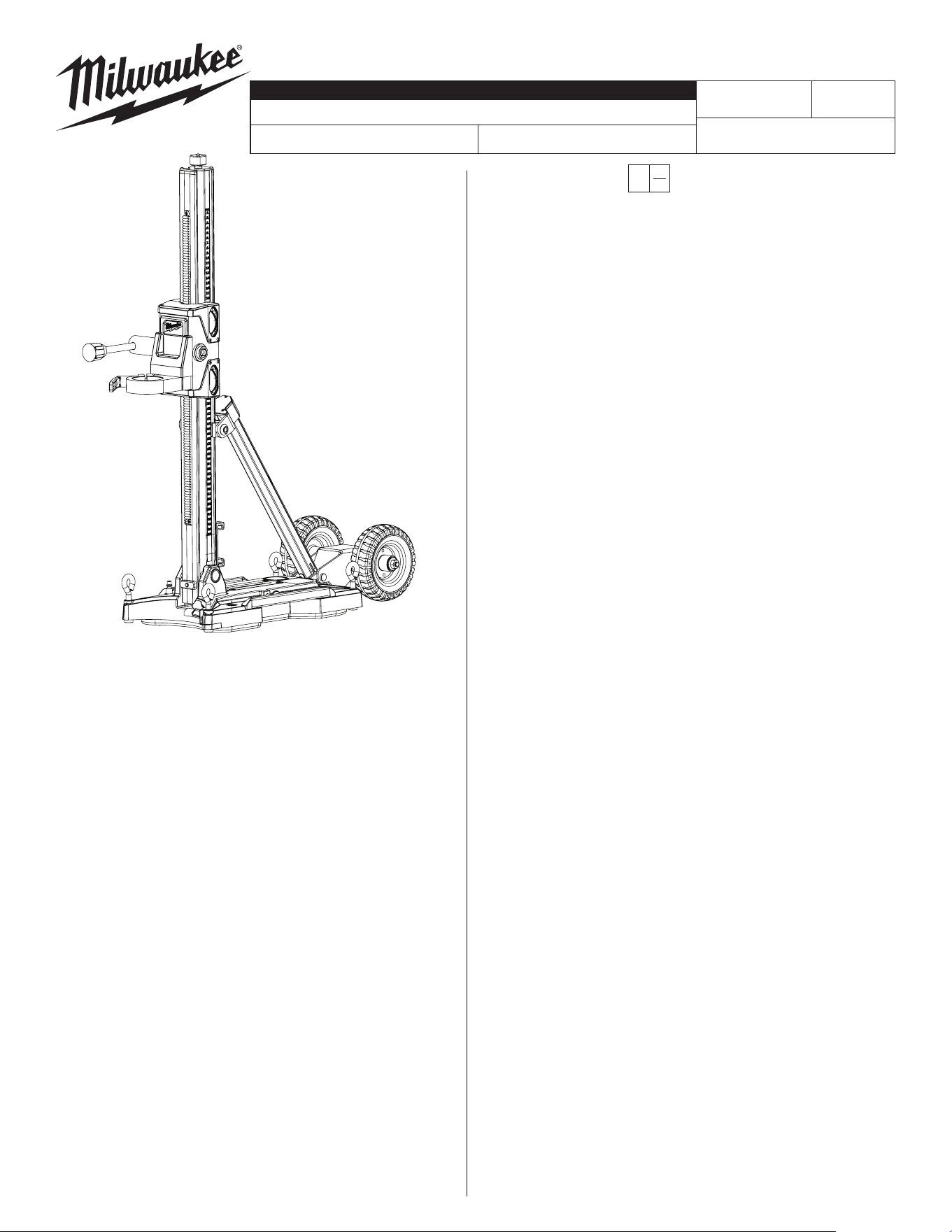
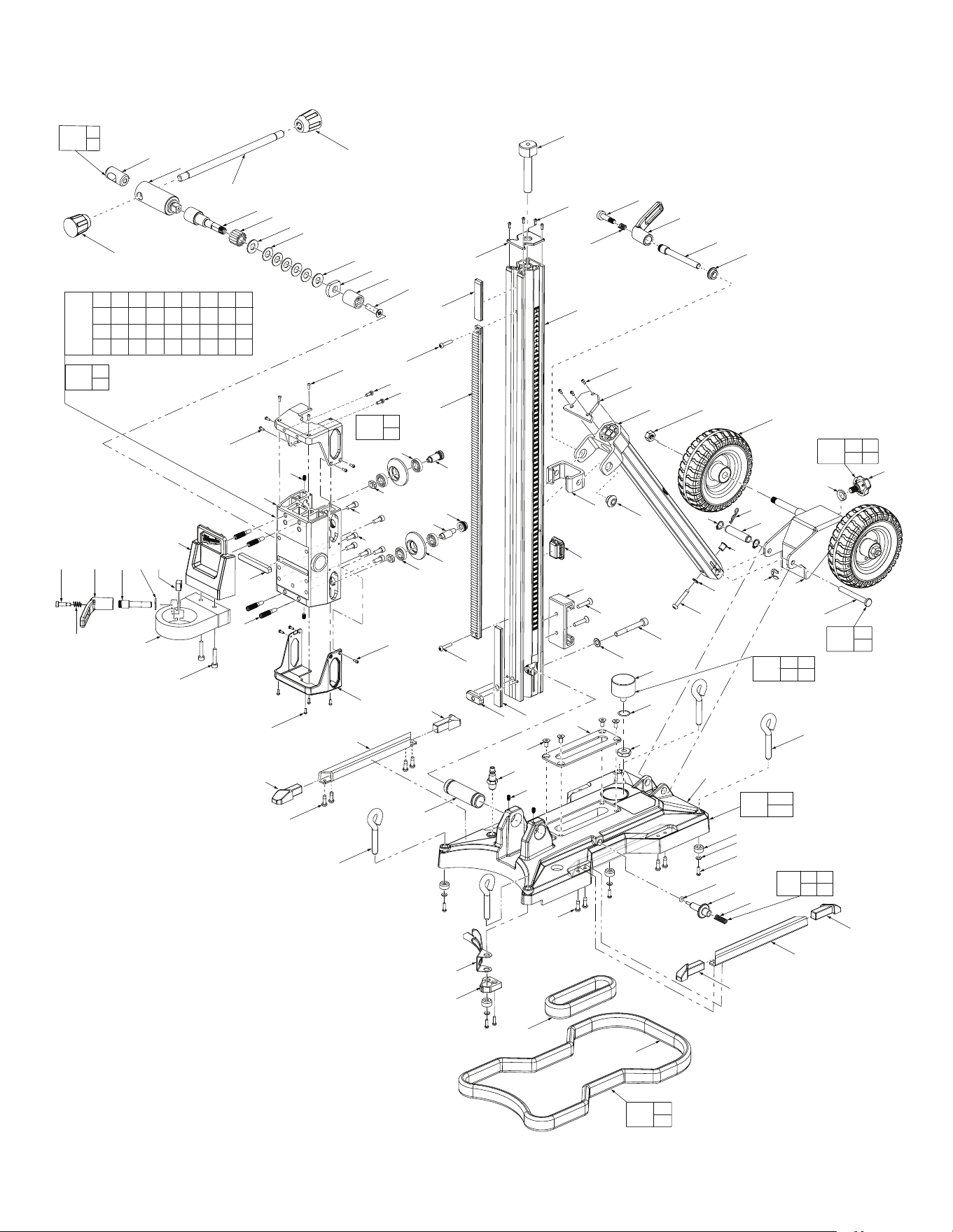
SERVICE PARTS LIST
BULLETIN NO.
Oct. 2024
EXAMPLE:
Component Parts (Small #) Are Included
When Ordering The Assembly (Large #).
00
0
WIRING INSTRUCTION
DATEREVISED BULLETIN
54-46-0010
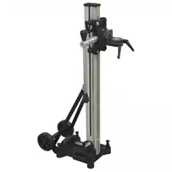
COMPACT CORE DRILL STAND
SPECIFY CATALOG NO. AND SERIAL NO. WHEN ORDERING PARTS
3000
CATALOG NO.
FIG. PART NO. DESCRIPTION OF PART NO. REQ.
1 --------------- Feed Handle Release Button (1)
2 43-98-0023 Feed Handle Knob (2)
3 43-62-0018 Feed Handle (1)
4 ---------------
Feed Handle Hub & Square Drive Assy
(1)
6 45-08-0019 Square Drive Rack/Gear Shaft (1)
7 36-66-0011 Rack Pinion (1)
9 45-88-0067 Washer (2)
10 40-50-0079 Disc Spring (5)
11 02-04-2150 Ball Bearing (8)
12 --------------- Carrier Wheel (4)
13 05-81-0015 M3 x 8.5mm Pan Hd. T-10 Mach. Scr. (23)
14 42-52-0017 Carrier Cap (2)
15 06-83-0014 M5 Set Screw w/ 2.5mm Hex Drive (4)
16 05-81-1338 M4 x 10mm Pan Hd. ST T-20 Screw (2)
17 45-04-1090 M6 x 16mm Cap Hd. Mach. Screw (2)
18 45-04-1090 M6 x 16mm Cap Hd. Mach. Screw (3)
19 42-24-0011 Bushing (4)
20 45-08-0022 Concentric Shaft (2)
21 45-08-0024 Eccentric Shaft (2)
22 06-55-0013 Threaded Nut (2)
23 44-60-0093 Set Pin (4)
24 43-96-0011 Carrier Flange Key (1)
25 --------------- Carrier (1)
26 43-34-0013 Logo Flange (1)
27 06-55-0015 Tool Free Handle Holder (1)
28 05-89-0013 Tool Free Screw Bolt (2)
29 40-50-0083 Tool Free Spring (2)
30 44-10-0017 Tool Free Handle (2)
31 05-89-0014 Tool Mount Screw Bolt (1)
32 45-88-0068 M10 Washer (1)
33 42-76-0012 Tool Mount Plate (1)
34 05-88-0051 M6 x 30mm Cap Hd. Mach. Screw (2)
35 44-66-0073 Wear Plate (1)
36 43-12-0010 Handle Square Driver (1)
37 45-22-0014 Column Sleeve (1)
40 42-52-0019 Column Cap (1)
41 42-76-0041 Rack Top Plate (1)
42 06-82-0058 M5 x 24mm Pan Hd. T-25 Mach. Scr. (2)
43 44-80-0010 Rack (1)
K29A
FIG. PART NO. DESCRIPTION OF PART NO. REQ.
44 42-78-0020 Column (1)
45 42-76-0042 Rack Bottom Plate (1)
50 43-72-0011 Battery Holder (1)
51 05-80-0011 M6 x 30mm Flat Hd. Mach. Screw (2)
52 06-75-0015 M8 x 65mm Cap Hd. Mach. Bolt (1)
53 45-88-0069 Washer (1)
54 42-52-0022 Angle Brace Cap (1)
55 42-36-0031 Angle Brace (1)
56 42-76-0043 Angle Adjustment Cap (1)
57 06-82-0073 M6 x 36mm Pan Hd. T-30 Mach. Scr. (1)
58 45-88-0011 Washer (1)
59 42-76-0044 Bevel Adjustment Cap (1)
60 45-24-0014 Angle Adjustment Slider (1)
61 42-40-0026 Bushing (1)
62 06-14-0011 Bevel Adjustment Screw Bolt (1)
63 06-55-0016 Lock Nut (2)
64 43-62-0031 Right Base Handle (1)
65 45-94-0012 Wheel (2)
66 45-60-0012 Wheel Support Weldment (1)
67 43-98-0051 Knob Screw (1)
68 --------------- Cotter Pin (1)
69 34-60-0026 Snap Ring (2)
70 45-22-0017 Angle Adjustment Sleeve (1)
71 --------------- Bolt (1)
72 42-52-0023 Left Handle Cap (2)
73 --------------- Base Stand (1)
74 42-52-0024 Right Handle Cap (2)
75 --------------- Vacuum Gauge (1)
76 --------------- O-Ring (1)
77 --------------- Gauge Nut (1)
78 05-80-0012 M6 x 12mm Flat Hd. Mach. Screw (4)
79 44-66-0074 Flat Plate (1)
80 42-90-0115 Air Valve, ARO Fitting (1)
45-80-0021 Air Valve, ARO Fitting (1)
45-80-0023 Air Valve, Global Hi-Flow Fitting (1)
45-80-0041 Air Valve, NITTO (1)
82 06-12-0011 Eye Bolt (4)
85 44-72-0011 Center Pointer (1)
86 --------------- Small Gasket (1)
87 --------------- Large Gasket (1)
88 34-40-0079 Seal Ring (1)
89 --------------- Vacuum Release Pin (1)
90 --------------- Vacuum Release Spring (1)
91 43-62-0033 Left Base Handle (1)
92 45-88-0171 Lock Washer (1)
93 42-52-0028 Bottom Board (4)
94 45-88-0018 Flat Washer (4)
95 05-88-1210 M4 x 14mm Pan Hd. T-20 Mach. Scr. (6)
96 45-52-1210 Point Stopper (1)
97 06-82-0029 M5 x 16mm Pan Hd. ST T-25 Screw (8)
98 --------------- E Clip (1)
99 05-88-1440 M6 x 20mm Flat Hd. Mach. Screw-LH (1)
100 43-78-0021 Handle Hub Assembly (1)
101 28-23-0010 Carrier Assembly (1)
102 45-94-0013 Carrier Wheel/Bearing Kit (1)
103 45-04-0013 Jack Screw Assembly (1)
105 45-52-0015 Stopper Assembly (1)
106 44-08-0010 Bubble Level Assembly (1)
107 28-06-0010 Base Assembly (1)
108 43-46-0013 Vacuum Gauge Kit (1)
109 14-46-0068 Bolt/Cotter Pin Kit (1)
110 43-98-0061 Knob Screw Kit (1)
111 44-20-0014 Vacuum Release Kit (1)
112 43-44-0019 Gasket Kit (1)
113 14-46-0907 Carrier Service Assembly (1)
120 12-20-0147 Service Nameplate (Not Shown) (1)
MILWAUKEE TOOL
l
www.milwaukeetool.com
13135 W. LISBON RD., BROOKFIELD, WI 53005
Drwg. 5
SERIAL NO.
10
(5x)
9
35
36
7
9
28
30
103
13(4x)
44
13(3x)
54
55
29
62
61
82(4x)
75
76
80
15(2x)
77
73
97(4x)
82(4x)
37
97(4x)
13(4x)
42
41
43
16(2x)
40
91
52
53
105
45
42
74
64
72a
72
14(2x)
51
50
59
60
58
56
57
71
98
66
69
70
79
78(4x)
74
85
96
87
86
93(4x)
94(4x)
95(4x)
88
89
90
6
3
99
1
63(2x)
65(2x)
68
67
92
4
13(4x)
26
25
18(3 x)
19(4x)
20(2x)
21(2x)
22(2x)
11(4x)
11(4x)
12(4x)
23(4x)
33
34(2x)
24
13(4x)
13(4x)
29
2
2
106
108
75 76
77
107
73
108
109
68
71
112
86
87
110
67
98
92
102
11
12
100
1
4
111
88
90
89
(2x)
17
(2x)
15
(2x)
28 30 31 32 27
1 2 3 4 6 7 9 10 11
12 13 14 15 16 17 19 20 21
22 23 24 26 27 28 29 30 31
32 33 34 35 36 99
113
101
25
35