
Visit our website at: http://www.harborfreight.com
Email our technical support at: [email protected]
58169
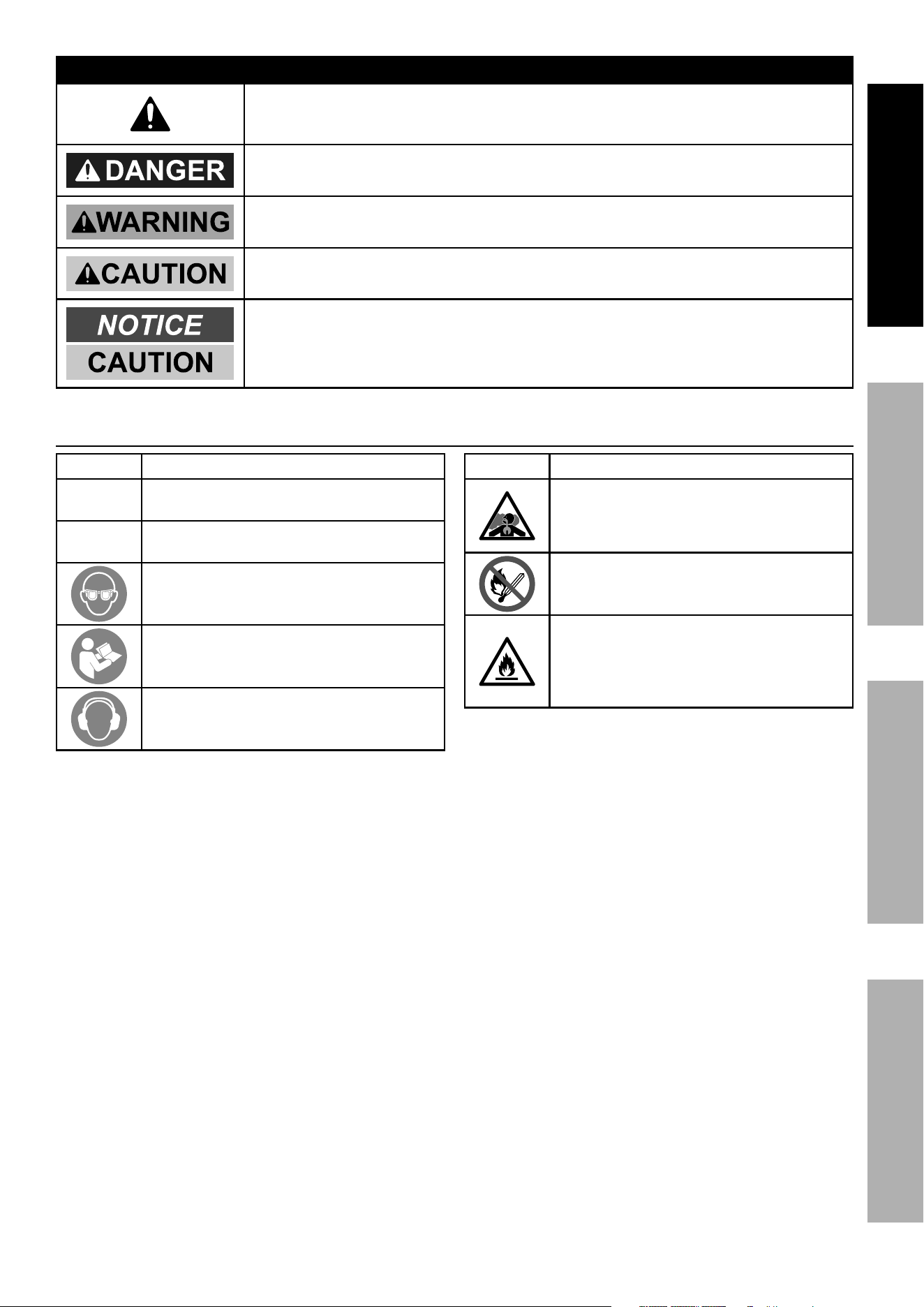
Using an engine indoors
CAN KILL YOU IN MINUTES.
Engine exhaust contains carbon monoxide.
This is a poison you cannot see or smell.
NEVER use inside
a home or garage,
EVEN IF doors and
windows are open.
Only use OUTSIDE
and far away from
windows, doors,
and vents.
Owner’s Manual & Safety Instructions
Save This Manual Keep this manual for the safety warnings and precautions, assembly,
operating, inspection, maintenance and cleaning procedures. Write the product’s serial number in the
back of the manual near the assembly diagram (or month and year of purchase if product has no number).
Keep this manual and the receipt in a safe and dry place for future reference. 21k
When unpacking, make sure that the product is intact
and undamaged. If any parts are missing or broken,
please call 1-888-866-5797 as soon as possible.
Copyright
©
2021 by Harbor Freight Tools
®
. All rights reserved.
No portion of this manual or any artwork contained herein may be reproduced in
any shape or form without the express written consent of Harbor Freight Tools.
Diagrams within this manual may not be drawn proportionally. Due to continuing
improvements, actual product may differ slightly from the product described herein.
Tools required for assembly and service may not be included.
Read this material before using this product.
Failure to do so can result in serious injury.
SAVE THIS MANUAL.
Owner’s Manual & Safety Instructions
Save This Manual Keep this manual for the safety warnings and precautions, assembly,
operating, inspection, maintenance and cleaning procedures. Write the product’s serial number in the
back of the manual near the assembly diagram (or month and year of purchase if product has no number).
Keep this manual and the receipt in a safe and dry place for future reference.
When unpacking, make sure that the product is intact
and undamaged. If any parts are missing or broken,
please call 1-888-866-5797 as soon as possible.
Copyright
©
2021 by Harbor Freight Tools
®
. All rights reserved.
No portion of this manual or any artwork contained herein may be reproduced in
any shape or form without the express written consent of Harbor Freight Tools.
Diagrams within this manual may not be drawn proportionally. Due to continuing
improvements, actual product may differ slightly from the product described herein.
Tools required for assembly and service may not be included.
Read this material before using this product.
Failure to do so can result in serious injury.
SAVE THIS MANUAL.
Owner’s Manual & Safety Instructions
Save This Manual Keep this manual for the safety warnings and precautions, assembly,
operating, inspection, maintenance and cleaning procedures. Write the product’s serial number in the
back of the manual near the assembly diagram (or month and year of purchase if product has no number).
Keep this manual and the receipt in a safe and dry place for future reference. 21k
When unpacking, make sure that the product is intact
and undamaged. If any parts are missing or broken,
please call 1-888-866-5797 as soon as possible.
Copyright
©
2021 by Harbor Freight Tools
®
. All rights reserved.
No portion of this manual or any artwork contained herein may be reproduced in
any shape or form without the express written consent of Harbor Freight Tools.
Diagrams within this manual may not be drawn proportionally. Due to continuing
improvements, actual product may differ slightly from the product described herein.
Tools required for assembly and service may not be included.
Read this material before using this product.
Failure to do so can result in serious injury.
SAVE THIS MANUAL.

Page 2 For technical questions, please call 1-888-866-5797. ITEM 58169
Table of Contents
Specifications ................................................................. 2
Safety ............................................................................. 3
Setup .............................................................................. 8
Operation ....................................................................... 12
Maintenance .................................................................. 16
Troubleshooting ............................................................. 20
Parts Lists and Diagrams .............................................. 22
Warranties ..................................................................... 26
Specifications
Cultivator Specifications
Tilling Depth 2" min – 6" max
Tilling Width 4" min – 9" max
Drive Type Worm Gear Drive
Drive Actuation Throttle Lever Operated
Depth Adjustment Steps 5
Overall Dimensions 31-1/2" L x 18-1/2" W x 40" H
Wheels 7" Diameter x 1-1/2" W
Weight 32.1 Pounds
Engine Specifications
Displacement 43 cc
Engine Type
Horizontal Single Cylinder
2-stroke
Cooling System Forced air cooled
Fuel
Type
87+ octane stabilizer-treated
unleaded gasoline containing no
more than 10% ethanol (E10) mixed
with 2-stroke oil (see below)
Capacity 0.27 Gallon
Oil
Type
2-stroke oil designed specifically
for mixing with gasoline. Must
meet either JASO M345 FD or
ISO-L-EGD requirements for air-
cooled engines, synthetic
Ratio
50:1 gasoline-to-oil ratio
2.6 oz oil per gallon of gasoline
Sound Level at 1 meter 95 dB
Bore x Stroke 40 mm x 34 mm
Compression Ratio 7.9:1
Rotation viewed from PTO
(power takeoff - the output shaft)
Counterclockwise
Spark Plug
Type Torch
®
L8RTC
Gap 0.0196" – 0.0275"
Speed Idle 2800 ± 280 RPM
The emissions control system for this Engine is warranted for standards set by the
U.S. Environmental Protection Agency. For warranty information, refer to the last pages of this manual.
Page 3For technical questions, please call 1-888-866-5797.ITEM 58169
SAFETYSETUpOpERATIONMAINTENANCE
WARNING SYMBOLS AND DEFINITIONS
This is the safety alert symbol. It is used to alert you to potential
personal injury hazards. Obey all safety messages that
follow this symbol to avoid possible injury or death.
Indicates a hazardous situation which, if not avoided,
will result in death or serious injury.
Indicates a hazardous situation which, if not avoided,
could result in death or serious injury.
Indicates a hazardous situation which, if not avoided,
could result in minor or moderate injury.
Addresses practices not related to personal injury.
Symbol Definitions
Symbol property or Statement
RpM
Revolutions Per Minute
Hp
Horsepower
WARNING marking concerning
Risk of Eye Injury. Wear ANSI-approved
safety goggles with side shields.
Read the manual before
set-up and/or use.
WARNING marking concerning
Risk of Hearing Loss.
Wear hearing protection.
Symbol property or Statement
WARNING marking concerning
Risk of Respiratory Injury.
Operate engine OUTSIDE and far away
from windows, doors, and vents.
WARNING marking concerning
Risk of Fire while handling fuel.
Do not smoke while handling fuel.
WARNING marking concerning
Risk of Fire.
Do not refuel while operating.
Keep flammable objects
away from engine.

Page 4 For technical questions, please call 1-888-866-5797. ITEM 58169
SAFETY SETUp OpERATION MAINTENANCE
IMpORTANT
Safe Operation practices for Walk-Behind
powered Rotary Tillers and Hand Supported Cultivators
WARNING! Read all instructions.
Failure to follow all instructions listed below may result in fire, serious injury and/or DEATH.
The warnings and precautions discussed in this manual cannot cover all possible conditions and
situations that may occur. It must be understood by the operator that common sense and caution
are factors which cannot be built into this product, but must be supplied by the operator.
SAVE THESE INSTRUCTIONS
Set up precautions
1. Thoroughly inspect the area where the equipment
is to be used and remove all foreign objects.
2. Disengage all clutches and shift into
neutral before starting the engine.
3. Gasoline fuel and fumes are flammable, and
potentially explosive. Take the following precautions:
a. Store fuel in containers specifically
designed for this purpose.
b. Refuel outdoors only and do not
smoke while refueling.
c. Add fuel before starting the engine. Never
remove the cap of the fuel tank or add fuel while
the engine is running or when the engine is hot.
d. If fuel is spilled, do not attempt to start the
engine but move the machine away from the
area of spillage and avoid creating any source
of ignition until fuel vapors have dissipated.
e. Replace all fuel tank and container caps securely.
4. Have multiple ABC class fire extinguishers nearby.
5. Do not operate the equipment without
wearing adequate protective clothing.
Wear protective footwear that will improve
footing on slippery surfaces.
6. Never attempt to make any adjustments
while the engine is running.
7. Operation of this equipment may create sparks that
can start fires around dry vegetation.
A spark arrestor may be required. The operator
should contact local fire agencies for laws or
regulations relating to fire prevention requirements.
8. Set up and use only on a flat, level,
well-ventilated surface.
9. Wear ANSI-approved safety goggles, heavy-duty
work gloves, and dust mask/respirator during set up.
10. Use only lubricants and fuel recommended
in the Specifications chart of this manual.
11. NEVER operate above or near any
electrical cables, gas pipes, or any other
utility lines. Contact your local utility
company before using the Cultivator.
12. Thoroughly inspect the area where the
Cultivator is to be used. Beware of possible
buried obstacles such as cable, conduit, irrigation
lines, and landscape fabric. Remove all large
sticks, stones, wires, or other foreign objects.
Training
1. Read the operating and service instruction manual
carefully. Be thoroughly familiar with the controls
and the proper use of the equipment. Know how to
stop the unit and disengage the controls quickly.
2. Never allow children to operate the
equipment. Never allow adults to operate
the equipment without proper instruction.
3. Keep the area of operation clear of all persons,
particularly small children, and pets.
4. Keep in mind that the operator or user is
responsible for accidents or hazards occurring to
other people, their property, and themselves.
Page 5For technical questions, please call 1-888-866-5797.ITEM 58169
SAFETYSETUpOpERATIONMAINTENANCE
Operating precautions
1. CARBON MONOXIDE HAZARD
Using an engine indoors
CAN KILL YOU IN MINUTES.
Engine exhaust contains
carbon monoxide. This is a poison
you cannot see or smell.
NEVER use inside a home or garage,
EVEN IF doors and windows are open.
Only use OUTSIDE and far away from windows,
doors, and vents.
2. Do not put hands or feet near or under rotating parts.
3. Exercise extreme caution when operating
on or crossing gravel drives, walks, or
roads. Stay alert for hidden hazards or
traffic. Do not carry passengers.
4. After striking a foreign object, stop the
engine, remove the wire from the spark
plug, thoroughly inspect the machine for
any damage, and repair the damage before
restarting and operating the machine.
5. If the unit should start to vibrate abnormally, stop
the engine and check immediately for the cause.
Vibration is generally a warning sign of trouble.
6. Stop the engine when leaving the operating
position, before unclogging the tines, and when
making any repairs, adjustments, and inspections.
7. Take all possible precautions when leaving
the machine unattended. Stop the engine
and remove the wire from the spark plug.
8. Before cleaning, repairing, or inspecting, shut
off the engine and make certain all moving
parts have stopped. Disconnect the spark
plug wire, and keep the wire away from
the plug to prevent accidental starting.
9. Do not operate the engine in a confined space
where dangerous carbon monoxide gas can collect.
10. Never operate the machine without proper guards,
plates, or other safety protective devices in place.
11. Never operate the Cultivator without
good visibility or light.
12. Do not use the Cultivator on steep inclines.
Use only on level ground surfaces.
13. Keep a safe distance from the edges and
banks of ditches. Avoid any actions that
may cause the Cultivator to tip over.
14. Be careful when operating in hard ground.
The tines may catch in the ground and propel
the tiller forward. If this occurs, let go of the
handlebars and do not restrain the machine.
15. Keep children away from the equipment,
especially while it is operating.
16. Keep all spectators at least six feet
from the Engine during operation.
17. Fire Hazard! Do not fill fuel tank while engine is
running. Do not operate if gasoline has been spilled.
Clean spilled gasoline before starting engine.
Do not operate near pilot light or open flame.
18. Do not touch engine during use.
Let engine cool down after use.
19. Never store fuel or other flammable
materials near the engine.
20. Only use a suitable means of transport and
lifting devices with sufficient weight bearing
capacity when transporting the equipment.
21. Secure the equipment on transport vehicles to
prevent it from rolling, slipping, and tilting.
22. Industrial applications must follow
OSHA requirements.
23. Do not leave the equipment unattended when it is
running. Turn off the equipment (and remove safety
keys, if available) before leaving the work area.
24. The equipment can produce high noise levels.
Prolonged exposure to noise levels
above 85 dBA is hazardous to hearing.
Wear ear protection when operating the equipment
or when working nearby while it is operating.
25. Wear ANSI-approved safety glasses,
hearing protection, heavy-duty work gloves
and steel-toed boots during use.
26. People with pacemakers should consult their
physician(s) before use. Electromagnetic fields in
close proximity to a heart pacemaker could cause
pacemaker interference or pacemaker failure.
Caution is necessary when near the
engine’s magneto or recoil starter.

Page 6 For technical questions, please call 1-888-866-5797. ITEM 58169
SAFETY SETUp OpERATION MAINTENANCE
27. Use only accessories that are recommended
by Harbor Freight Tools for your model.
Accessories that may be suitable for one
piece of equipment may become hazardous
when used on another piece of equipment.
28. Do not operate in explosive atmospheres,
such as in the presence of flammable
liquids, gases, or dust. Gasoline-powered
engines may ignite the dust or fumes.
29. Stay alert, watch what you are doing and use
common sense when operating this piece of
equipment. Do not use while tired or under the
influence of drugs, alcohol or medication.
30. Do not overreach. Keep proper footing and
balance at all times. This enables better control
of the equipment in unexpected situations.
31. Use this equipment with both hands only.
Using equipment with only one hand
can easily result in loss of control.
32. Dress properly. Do not wear loose clothing or
jewelry. Keep hair, clothing and gloves away
from moving parts. Loose clothes, jewelry or
long hair can be caught in moving parts.
33. Parts, especially exhaust system components,
get very hot during use. Stay clear of hot parts.
34. Do not cover the equipment during operation.
35. Keep the equipment and engine clean at all times.
36. Do not operate the equipment with known
leaks in the engine’s fuel system.
37. When spills of fuel or oil occur, they must be
cleaned up immediately. Dispose of fluids and
cleaning materials as per any local, state, or
federal codes and regulations. Store oil rags in
a bottom-ventilated, covered, metal container.
38. Before use, check for misalignment or binding of
moving parts, breakage of parts, and any other
condition that may affect the equipment’s operation.
If damaged, have the equipment serviced
before using. Many accidents are caused
by poorly maintained equipment.
39. Use the correct equipment for the application.
Do not modify the equipment and do not use the
equipment for a purpose for which it is not intended.

Page 7For technical questions, please call 1-888-866-5797.ITEM 58169
SAFETYSETUpOpERATIONMAINTENANCE
Service precautions
1. Before service, maintenance, or cleaning:
a. Turn the Engine Switch to its “OFF” position.
b. Allow the Engine to completely cool.
c. Then, remove the Spark plug Cap
from the Spark plug.
2. Keep machine, attachments, and accessories in
safe working condition. Keep all safety guards
in place and in proper working order. Safety
guards include muffler, air cleaner, mechanical
guards, and heat shields, among other guards.
3. Do not alter or adjust any part of the
equipment or its engine that is sealed by the
manufacturer or distributor. Only a qualified
service technician may adjust parts that may
increase or decrease governed engine speed.
4. Check shear bolts, engine mounting bolts, and other
bolts at frequent intervals for proper tightness to be
sure the equipment is in safe working condition.
5. Never store the machine with fuel in the fuel
tank inside a building where ignition sources are
present, such as hot water and space heaters,
clothes dryers, and the like. Allow the engine
to cool before storing in any enclosure.
6. If the fuel tank has to be drained, do this outdoors.
7. Do not store fuel or other flammable
materials near the engine.
8. Wear ANSI-approved safety goggles,
heavy-duty work gloves, and
dust mask/respirator during service.
9. Maintain labels and nameplates on the equipment.
These carry important information.
If unreadable or missing, contact
Harbor Freight Tools for a replacement.
10. Have the equipment serviced by a qualified repair
person using only identical replacement parts.
This will ensure that the safety of the equipment
is maintained. Do not attempt any service or
maintenance procedures not explained in this
manual or any procedures that you are uncertain
about your ability to perform safely or correctly.
11. Store equipment out of the reach of children.
12. Follow scheduled engine and
equipment maintenance.
Refueling:
1. Do not refill the fuel tank while the
engine is running or hot.
2. Do not smoke, or allow sparks, flames,
or other sources of ignition around the
equipment, especially when refuelling.
3. Do not fill fuel tank to the top.
Leave a little room for the fuel to expand as needed,
at least 1 inch from top of the neck.
TO pREVENT FUEL LEAKAGE AND
FIRE HAZARD, do not fill fuel above
the bottom of the threads.
4. Refuel in a well-ventilated area only.
5. Wipe up any spilled fuel and allow excess
to evaporate before starting engine.
To prevent FIRE, do not start the engine
while the smell of fuel hangs in the air.
SAVE THESE INSTRUCTIONS.
Page 8 For technical questions, please call 1-888-866-5797. ITEM 58169
SAFETY SETUp OpERATION MAINTENANCE
Set Up
Read the ENTIRE IMpORTANT SAFETY INFORMATION section at the beginning of this manual
including all text under subheadings therein before set up or use of this product.
TO pREVENT SERIOUS INJURY: Operate only with proper spark arrestor installed.
Operation of this equipment may create sparks that can start fires around dry vegetation.
A spark arrestor may be required. The operator should contact local fire agencies for laws or
regulations relating to fire prevention requirements.
TO pREVENT SERIOUS INJURY FROM ACCIDENTAL STARTING: Turn the power Switch
of the equipment to its “OFF” position, wait for the engine to cool, and unplug the spark
plug wire(s) before assembling or making any adjustments to the equipment.
At high altitudes, the engine’s carburetor, governor (if so equipped), and any other parts that control
the fuel-air ratio will need to be adjusted by a qualified mechanic to allow efficient high-altitude
use and to prevent damage to the engine and any other devices used with this product.
Assembly
Note: For additional information regarding the parts listed in the following pages,
refer to the Assembly Diagram near the end of this manual.
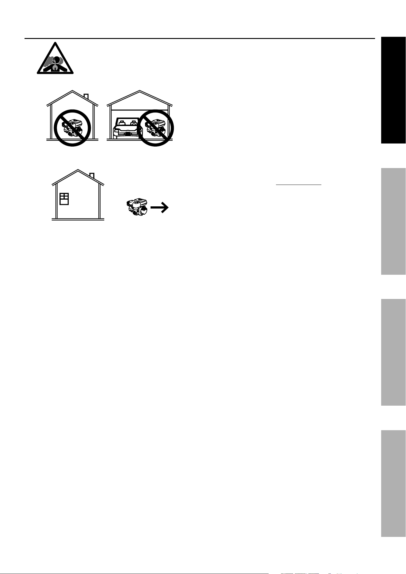
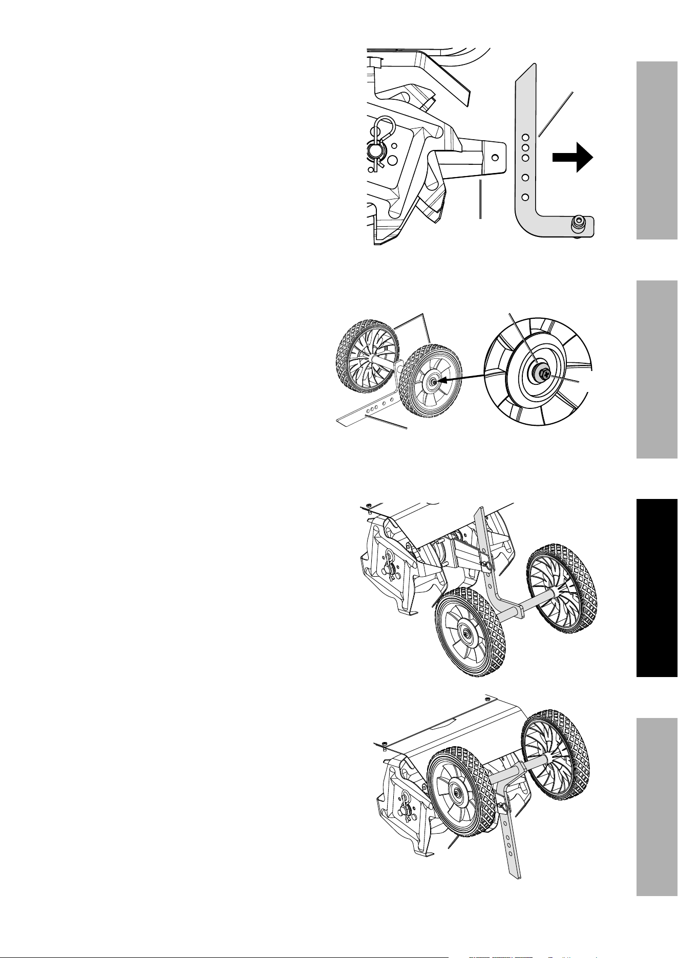
Axle / Drag Bar and Wheel Assembly
1. Remove the R-Clip (26) from the
Clevis Pin (29) holding the Axle / Drag
Bar Assembly (25) in place.
2. Remove the Clevis Pin from the
Axle / Drag Bar Assembly.
R-Clip
Axle /
Drag Bar
Assembly
Clevis
pin
Clevis
pin
Axle /
Drag Bar
Assembly
Page 9For technical questions, please call 1-888-866-5797.ITEM 58169
SAFETYSETUpOpERATIONMAINTENANCE
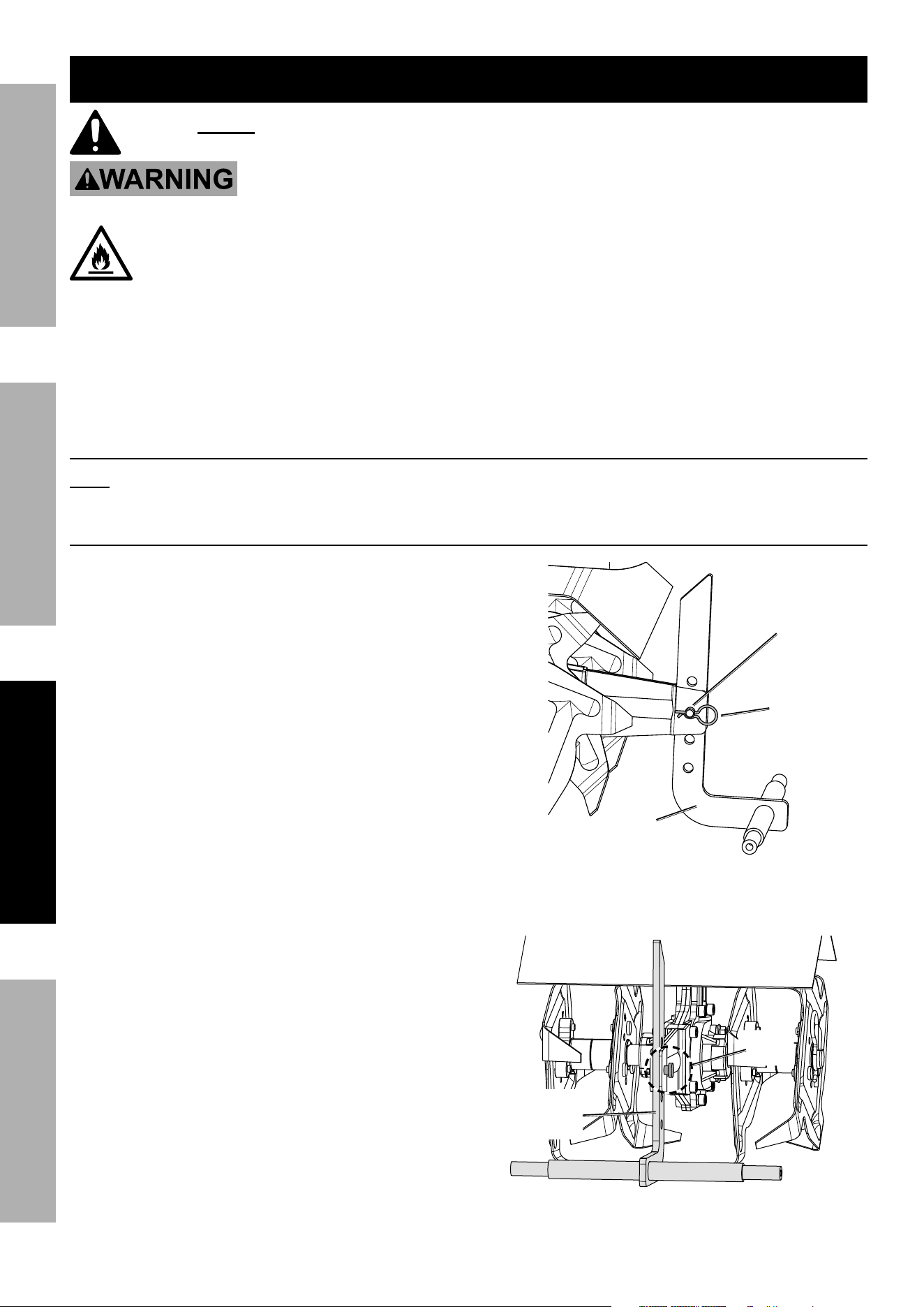
3. Remove the Axle / Drag Bar Assembly from the
bracket on the Cultivator.
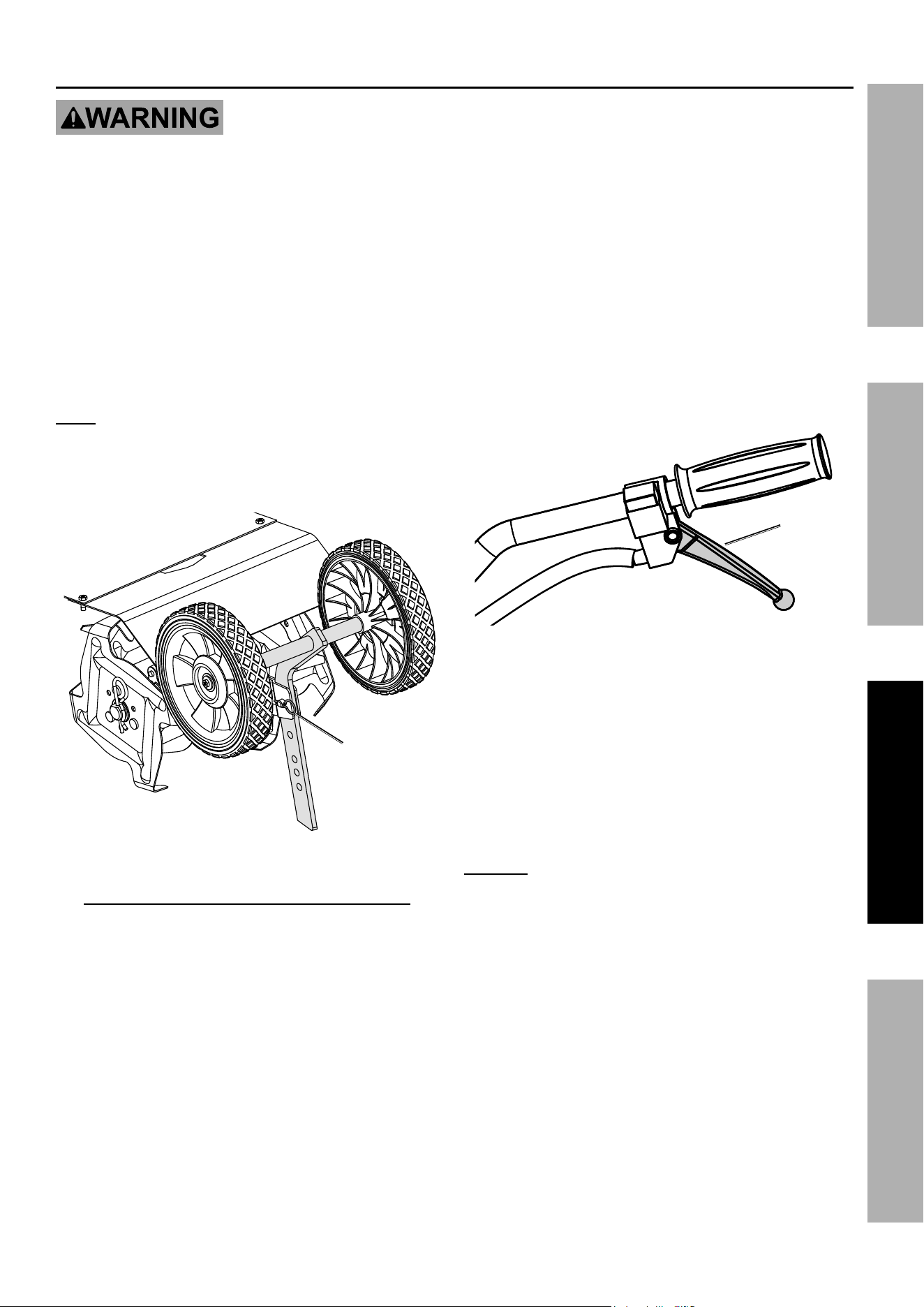
4. Attach the two Wheels (24) onto the
Axle / Drag Bar Assembly in orientation
shown using one M6 x12 Screw (22) and
Ø6 Washer (23) per Wheel.
5. Attach the completed Axle / Drag Bar
Assembly onto the bracket on the
Cultivator using the R-Clip and Clevis
Pin removed in steps 1 and 2.
Attach the Axle / Drag Bar Assembly in the
rolling position with the Drag Bar facing
up as shown for moving the Cultivator
before and after use. For cultivating
change the direction to the working
position with the Drag Bar facing down.
Bracket
Axle /
Drag Bar
Assembly
M6 x12 M6 x12
ScrewScrew
Ø6 Washer
Wheels
Axle / Drag Bar
Assembly
Rolling
position
Working
position
Page 10 For technical questions, please call 1-888-866-5797. ITEM 58169
SAFETY SETUp OpERATION MAINTENANCE
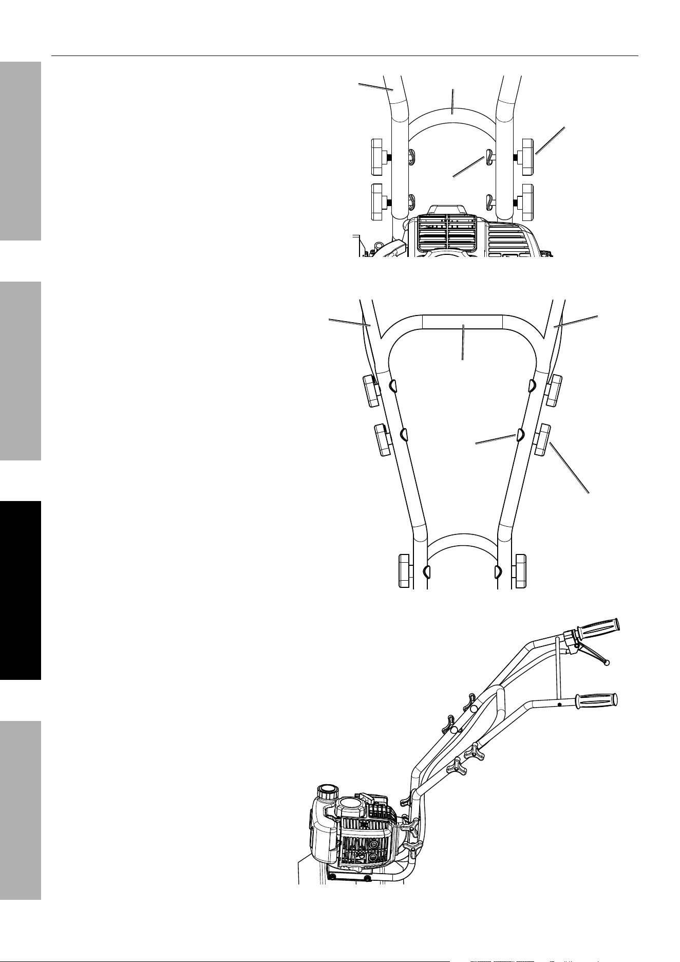
Handle Assembly
1. Attach the Middle Handle (12) to the
Lower Handle (17) using four M8 x 45
Capscrews (14), Ø8 Flat Washers (58),
Ø8 Lock Washers (59), and Knobs (15).
Make sure the Knobs are on the outside.
2. Attach the Right Handle (11) and Left
Handle (13) to the Middle Handle
using four M8 x 45 Capscrews (14),
Ø8 Flat Washers (58), Ø8 Lock
Washers (59), and Knobs (15). Make
sure the Knobs are on the outside.
3. Completed Handle Assembly.
Middle
Handle
M8 x 45
Capscrew
Lower
Handle
Ø8 Flat Washer,
Ø8 Lock Washer
& Knob
Right
Handle
Left
Handle
Middle
Handle
M8 x 45
Capscrew
Ø8 Flat Washer,
Ø8 Lock Washer
& Knob
Page 11For technical questions, please call 1-888-866-5797.ITEM 58169
SAFETYSETUpOpERATIONMAINTENANCE
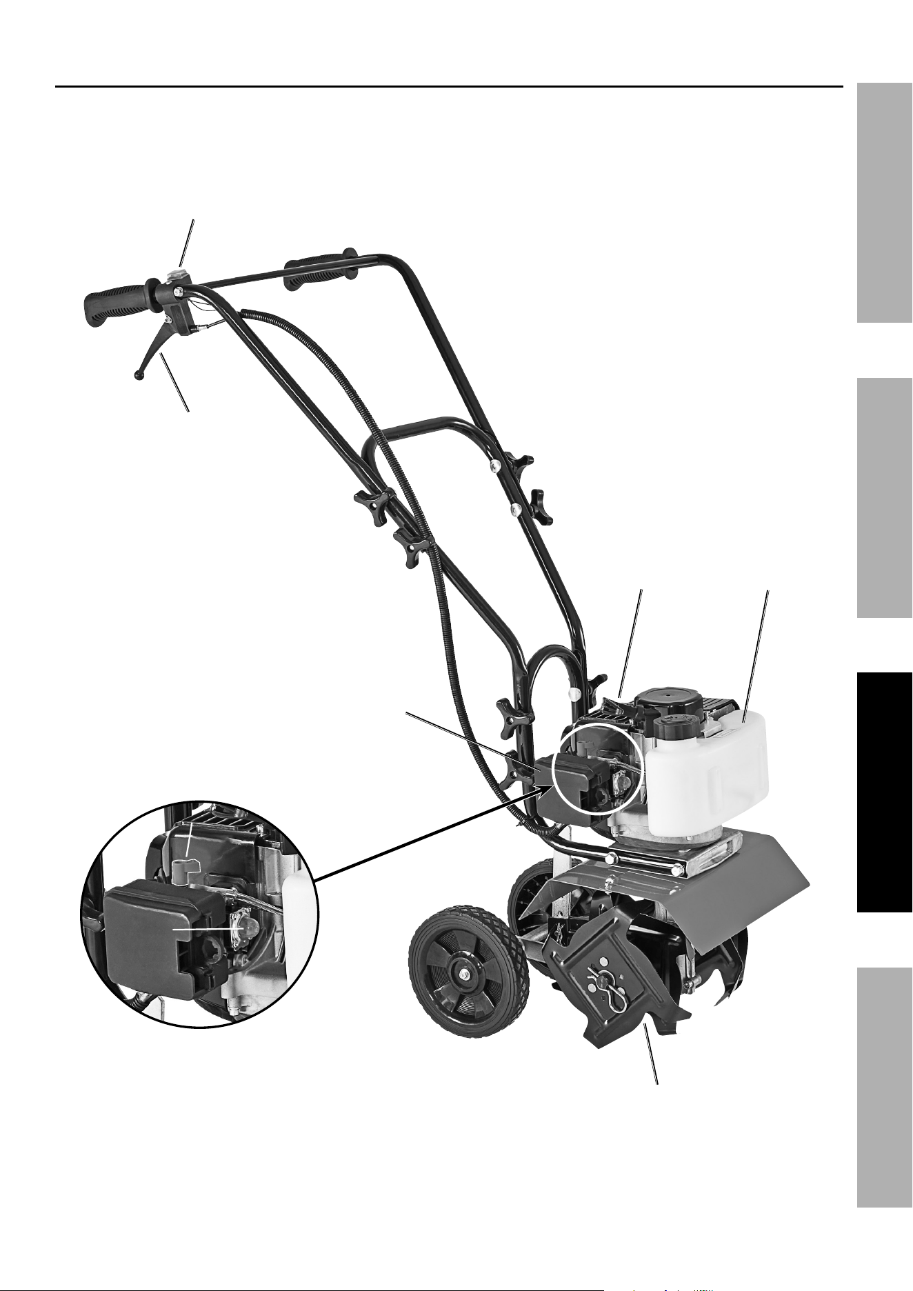
Components and Controls
ChokeChoke
Prime Prime
BulbBulb
Fuel
Tank
Air
Filter
Tines
Engine
Switch
Throttle
Control
Lever
Starter
Handle
Page 12 For technical questions, please call 1-888-866-5797. ITEM 58169
SAFETY SETUp OpERATION MAINTENANCE
Operation
Read the ENTIRE IMpORTANT SAFETY INFORMATION section at the beginning of this manual
including all text under subheadings therein before set up or use of this product.
pre-Start Checks
Inspect engine and equipment looking for damaged, loose, and missing parts before set up and starting.
If any problems are found, do not use equipment until fixed properly.
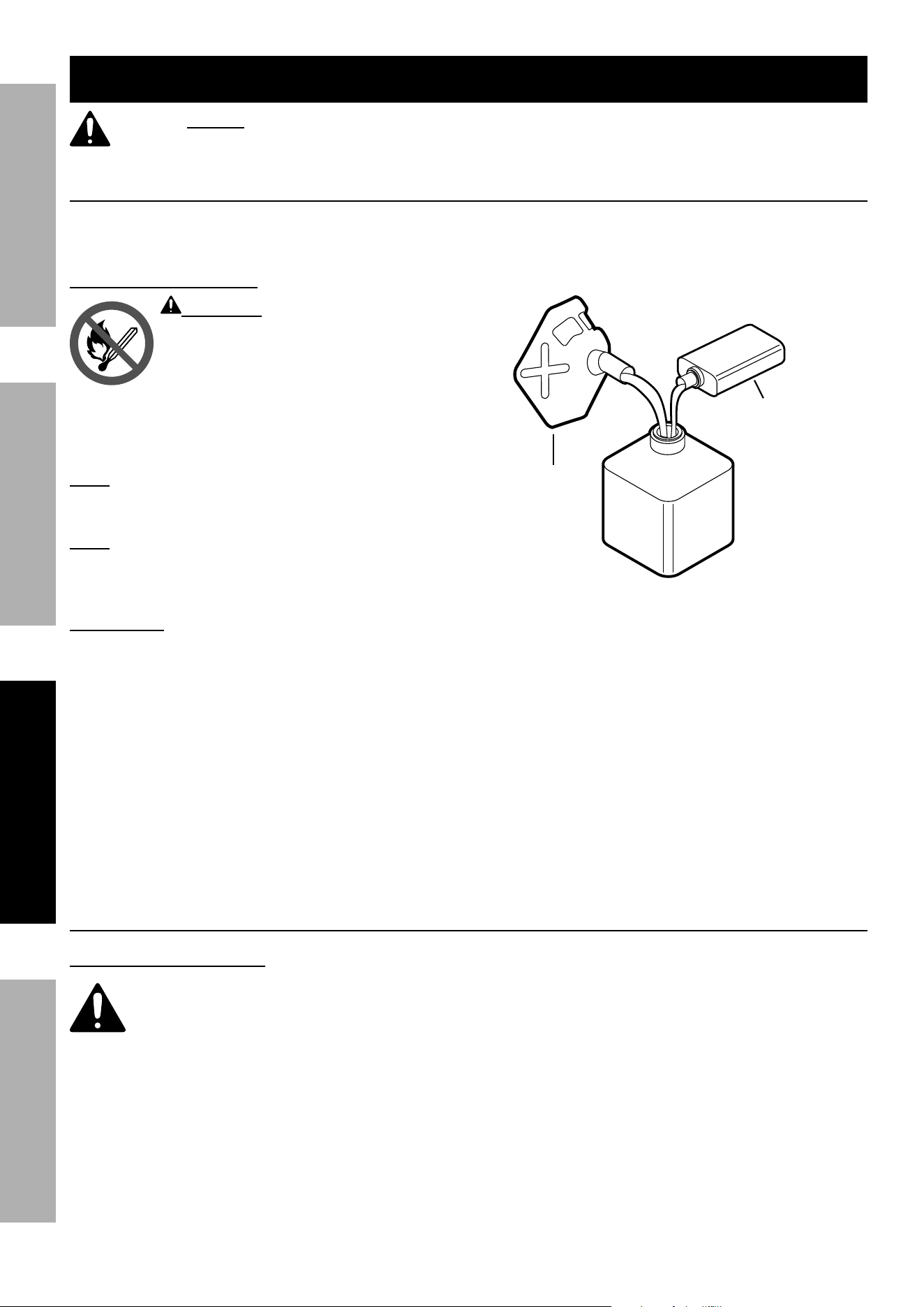
Checking and Filling Fuel
WARNING! TO pREVENT SERIOUS
INJURY FROM FIRE:
Fill the fuel tank in a well-ventilated area
away from ignition sources. If the engine
is hot from use, shut the engine off and
wait for it to cool before adding fuel. Do not smoke.
1. Clean the Fuel Cap and the area around it.
2. Unscrew and remove the Fuel Cap.
Note: Do not use gasoline containing more than
10% ethanol (E10). Do not use E85 ethanol. Add fuel
stabilizer to the gasoline or the Warranty is VOID.
Note: Do not use gasoline that has been stored in a
metal fuel container or a dirty fuel container. It can
cause particles to enter the carburetor, affecting
engine performance and/or causing damage.
IMpORTANT: Your Warranty is VOID if the Engine’s
Fuel Tank is not filled with the proper mixture (50:1) of
stabilizer-treated unleaded gasoline and 2-cycle oil
before each use.
2-Stroke oil must meet either JASO M345 FD or ISO-
L-EGD requirements for air-cooled engines, synthetic.
Before each use, check the fuel level. Do not run the
Engine with an improper unleaded gasoline/2-cycle oil
mixture. Running the Engine with an improper
mixture WILL permanently damage the Engine.
1 GALLON
UNLEADED
GASOLINE
2.6 FLUID OUNCES
2-CYCLE OIL
AppROVED
CONTAINER
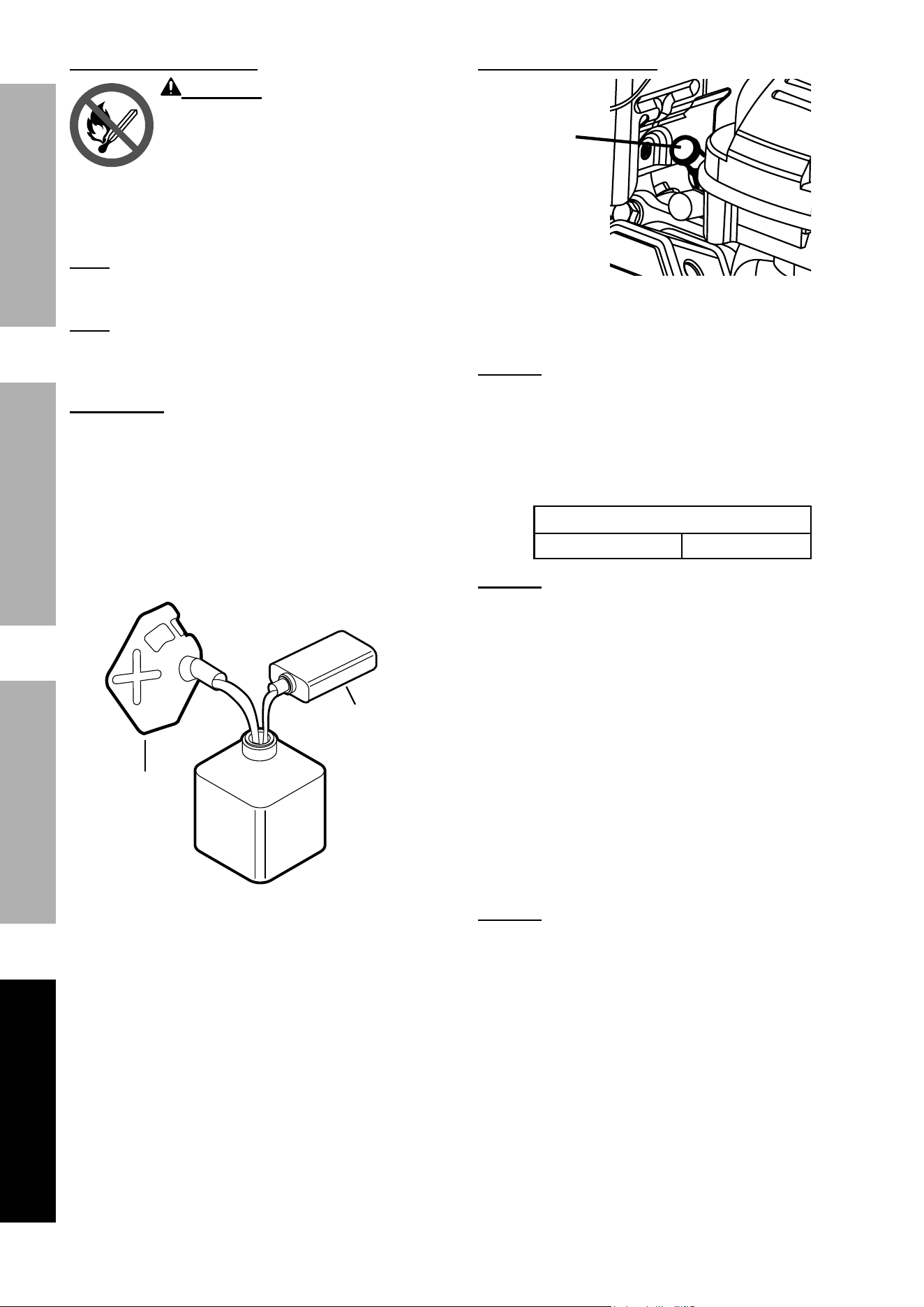
Fuel-Oil Mixture
3. To obtain the proper gasoline and 2-cycle oil
mixture, mix 2.6 fluid ounces of 2-cycle oil with
1 gallon of stabilizer-treated unleaded gasoline
into an approved container. Then gently agitate the
container to thoroughly mix the gasoline/2-cycle oil.
4. If needed, fill the Fuel Tank to about 1 inch
under the fill neck of the Fuel Tank with the
pre-mixed unleaded gasoline/2-cycle oil mixture.
5. Then replace the Fuel Cap.
6. Wipe up any spilled fuel and allow excess
to evaporate before starting engine.
To prevent FIRE, do not start the engine
while the smell of fuel hangs in the air.
Starting the Engine
Before Starting the Engine
a. Inspect the equipment and engine.
b. Fill the engine fuel tank with the proper amount and type of stabilizer-
treated unleaded gasoline and 2-cycle oil mixture.
Page 13For technical questions, please call 1-888-866-5797.ITEM 58169
SAFETYSETUpOpERATIONMAINTENANCE
Manual Start
A “cold start” is when the engine is no
longer hot to the touch, typically at least
30 minutes after it has last been run.
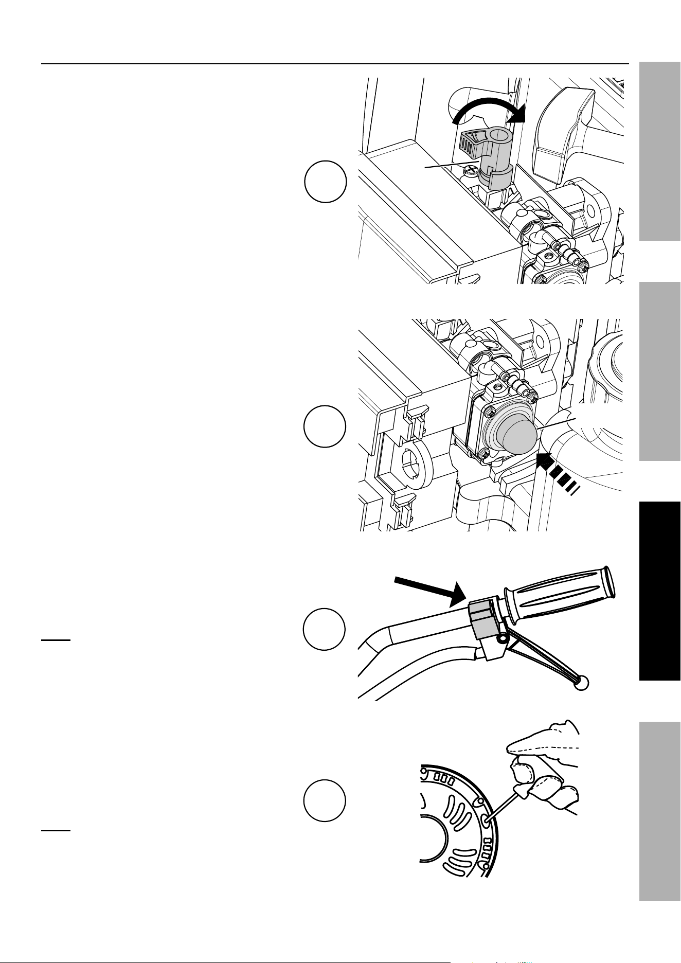
1. To start a cold Engine, turn the
Choke Knob clockwise to the
START (closed) position.
2. Press the Prime Bulb 7–10 times until
fuel can be seen in the fuel line.
3. Turn the Engine Switch ON.
Note: Do not pull on the Throttle Control
Lever when starting the Engine.
4. Grip the Starter Handle of the Engine
loosely and pull it gently until resistance is
felt. Allow Cable to retract fully and then pull
it quickly. Repeat until the Engine starts.
Note: Do not let the Starter Handle snap
back against the Engine. Hold it as it
recoils so it doesn’t hit the Engine.
1
Choke
Knob
2
prime
Bulb
3
Turn Switch ON
4
Page 14 For technical questions, please call 1-888-866-5797. ITEM 58169
SAFETY SETUp OpERATION MAINTENANCE
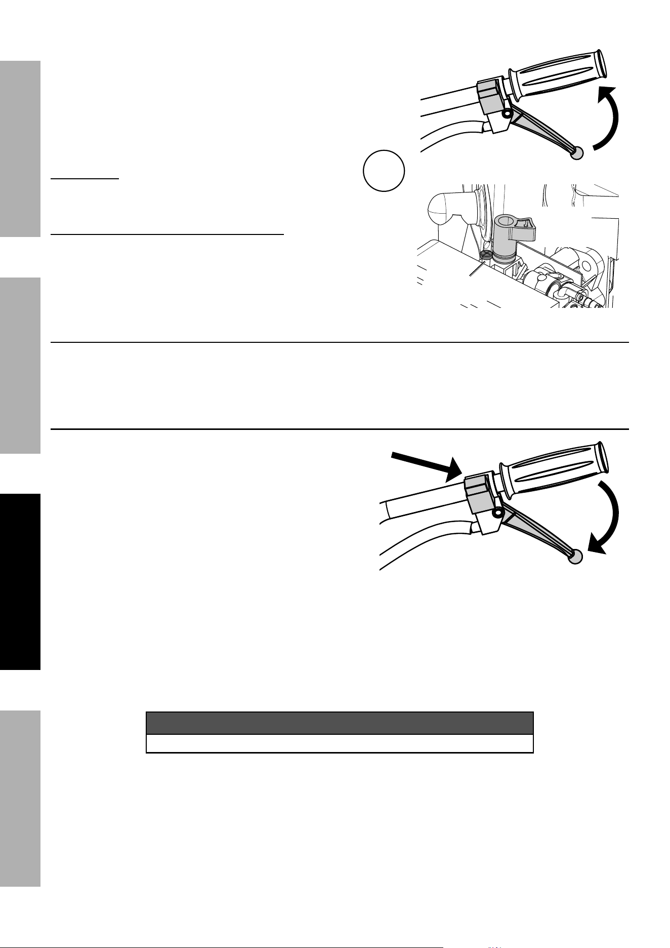
5. Allow the Engine to run for 10 –15 seconds with
the Choke in the START position. Then pull up
on the Throttle Control Lever to automatically
move the Choke lever to its RUN (open)
position. Release the Throttle Lever.
IMpORTANT: Allow the Engine to to warm
up at idle for 2–3 minutes after each start-up
so that the Engine can stabilize.
WARNING! TO pREVENT SERIOUS INJURY:
If the Tines rotate with the Engine idling and the
Throttle Control Lever fully released, turn the Idle
Adjustment Screw counterclockwise to decrease
idle speed until the Tines stop rotating.
To Restart a Warm Engine
Leave the Choke in Run position. If Choke is not in Run position pull and release the Throttle
Control Lever to return Choke to its RUN position and follow Steps 3 and 4 in the starting
instructions above. If Engine fails to start use the cold engine starting procedure.
Stopping the Engine
1. To stop the engine in an emergency,
release the Throttle Control Lever and
turn the Engine Switch OFF.
2. Under normal conditions, use the following procedure:
a. Release the Throttle Control Lever.
b. Let Engine idle for 1 – 2 minutes.
c. Turn the Engine Switch OFF.
d. Clean external parts with clean cloth, remove debris from Tine Blades and Shaft, then cover the
equipment and store in a dry, level, well-ventilated area out of reach of children. Under normal operating
conditions subsequent maintenance follows the schedule explained in the MAINTENANCE section.
NOTICE
See Long-Term Storage on page 19 for complete storage instructions.
pull
Throttle
Lever Up
Choke
in Run
position
Idle
Adjustment
Screw
5
Turn Switch OFF
Release
Throttle
Lever
Page 15For technical questions, please call 1-888-866-5797.ITEM 58169
SAFETYSETUpOpERATIONMAINTENANCE
Cultivator Operation
TO pREVENT SERIOUS INJURY: Keep hands, fingers, feet, and loose clothing away from rotating Tines.
BEWARE of possible buried obstacles such as cable, conduit, irrigation lines, and landscape fabric.
DO NOT operate above or near any electrical cables, gas pipes, or any other
utility lines. Contact your local utility company before using the Cultivator.
1. Before starting the Engine, place the Axle / Drag
Bar Assembly in the cultivating position and set the
desired cultivating depth (to a maximum 6" deep)
by adjusting the Axle / Drag Bar Assembly:
Remove the R-Clip and Clevis Pin holding the
Assembly in place. Lower the Assembly to
increase cultivating depth or raise it to decrease
depth. Replace the Clevis Pin and R-Clip.
Note: Optimum tilling depth (generally 4"– 6") will vary
with soil conditions. If Cultivator shakes or is difficult
to control, the Axle / Drag Bar Assembly is not correctly
set for the conditions. Adjustment through trial and
error is required to achieve the correct setting.
Axle / Drag Bar Assembly
in Cultivating position
R-Clip and R-Clip and
Clevis pin
2. WARNING! TO pREVENT SERIOUS INJURY:
Before first use, practice operating the Cultivator
controls with Tines raised off of the ground.
Know how to keep control at all times, how to
stop the Tines from turning, and how to stop the
Engine. For actual field use, operate at a slow
pace until familiar with Cultivator handling.
3. Start the Engine following instructions
in Manual Start on page 13.
4. Grip the Handles firmly with both hands.
5. With the Engine running, pull up on the Throttle
Control Lever on the Handlebar to rotate the Tines
and move forward. Release the Throttle Control
Lever to stop Tine rotation and forward movement.
Throttle
Control
Lever
6. The following soil conditions can affect tilling results:
a. On soil that is too hard and/or dried out for the
Tines to penetrate, the Cultivator will shake
excessively and jump across the soil surface.
Moisten dry, hardened soil prior to tilling and use
a shallow depth setting and slow Engine speed.
b. Exceedingly wet soil will form clumps
during tilling and clog the Tines. Allow wet
soil to partially dry before tilling and use a
slow Engine speed to improve results.
NOTICE: Should the Tines jam or the Cultivator strike
a foreign object during use, immediately release the
Throttle Control Lever and turn off the Engine. Wait
until the machine completely stops. Disconnect the
Spark Plug cap, remove foreign objects and inspect the
Cultivator. If any damage is found have the problem
corrected before further use.

Page 16 For technical questions, please call 1-888-866-5797. ITEM 58169
SAFETY SETUp OpERATION MAINTENANCE
Maintenance
WARNING
TO pREVENT SERIOUS INJURY FROM ACCIDENTAL STARTING:
Turn the power Switch of the equipment to its “OFF” position, wait for the engine to cool, and disconnect
the spark plug cap before performing any inspection, maintenance, or cleaning procedures.
TO pREVENT SERIOUS INJURY FROM EQUIpMENT FAILURE:
Do not use damaged equipment. If abnormal noise, vibration, or excess
smoking occurs, have the problem corrected before further use.
Follow all service instructions in this manual. The engine may fail critically if not serviced properly.
Many maintenance procedures, including any not detailed in this manual, will need to be performed
by a qualified technician for safety. If you have any doubts about your ability to safely service the
equipment or engine, have a qualified technician service the equipment instead.

Page 17For technical questions, please call 1-888-866-5797.ITEM 58169
SAFETYSETUpOpERATIONMAINTENANCE
Cleaning, Maintenance, and Lubrication Schedule
Note: This maintenance schedule is intended solely as a general guide. If performance decreases or if
equipment operates unusually, check systems immediately. The maintenance needs of each piece of equipment
will differ depending on factors such as duty cycle, temperature, air quality, fuel quality, and other factors.
Note: The following procedures are in addition to the regular checks and maintenance
explained as part of the regular operation of the engine and equipment.
procedure
Before
Each
Use
After
Each
Use
Monthly or
every 20
hr. of use
Every 3 mo.
or 50 hr.
of use
Every 6 mo.
or 100 hr.
of use
Yearly or
every 300
hr. of use
Every
2 Years
Brush off outside of engine
Check engine fuel/oil mixture level
Check for loose hardware
Check/adjust idle speed
Clean debris from Tine
Blades and Shaft
Clean air filter
*
Check sediment cup
Check and clean spark plug
1. Clean fuel tank, strainer
and carburetor
2. Clean carbon build-up from
combustion chamber
** **
Replace fuel line if necessary
**
*Service more frequently when used in dusty areas.
**These items should be serviced by a qualified technician.
Page 18 For technical questions, please call 1-888-866-5797. ITEM 58169
SAFETY SETUp OpERATION MAINTENANCE
Checking and Filling Fuel
WARNING! TO pREVENT SERIOUS
INJURY FROM FIRE:
Fill the fuel tank in a well-ventilated area
away from ignition sources. If the engine is
hot from use, shut the engine off and wait
for it to cool before adding fuel. Do not smoke.
1. Clean the Fuel Cap and the area around it.
2. Unscrew and remove the Fuel Cap.
Note: Do not use gasoline containing more than
10% ethanol (E10). Do not use E85 ethanol. Add fuel
stabilizer to the gasoline or the Warranty is VOID.
Note: Do not use gasoline that has been stored in a
metal fuel container or a dirty fuel container. It can
cause particles to enter the carburetor, affecting
engine performance and/or causing damage.
IMpORTANT: Your Warranty is VOID if the Engine’s
Fuel Tank is not filled with the proper mixture (50:1) of
stabilizer-treated unleaded gasoline and 2-cycle oil
before each use.
2-Stroke oil must meet either JASO M345 FD or ISO-
L-EGD requirements for air-cooled engines, synthetic.
Before each use, check the fuel level. Do not run the
Engine with an improper unleaded gasoline/2-cycle oil
mixture. Running the Engine with an improper
mixture WILL permanently damage the Engine.
1 GALLON
UNLEADED
GASOLINE
2.6 FLUID OUNCES
2-CYCLE OIL
AppROVED
CONTAINER
Figure B: Fuel-Oil Mixture
3. To obtain the proper gasoline and 2-cycle oil
mixture, mix 2.6 fluid ounces of 2-cycle oil with
1 gallon of stabilizer-treated unleaded gasoline
into an approved container. Then gently agitate the
container to thoroughly mix the gasoline/2-cycle oil.
4. If needed, fill the Fuel Tank to about 1 inch
under the fill neck of the Fuel Tank with the
pre-mixed unleaded gasoline/2-cycle oil mixture.
5. Then replace the Fuel Cap.
6. Wipe up any spilled fuel and allow excess
to evaporate before starting engine.
To prevent FIRE, do not start the engine
while the smell of fuel hangs in the air.
Spark plug Maintenance
1.
Spark
plug
Cap
Disconnect spark plug cap from end of plug.
Clean out debris from around spark plug.
2. Using a spark plug wrench, remove the spark plug.
NOTICE: Do not remove spark plug when Engine
is hot or possible damage to threads may occur.
3. Inspect the spark plug:
If the electrode is oily, clean it using a clean, dry rag.
If the electrode has deposits on it, polish it using
emery paper. If the white insulator is cracked or
chipped, the spark plug needs to be replaced.
Recommended Spark plug
TORCH
®
L8RTC
NOTICE: Using an incorrect spark plug
may damage the engine.
4. When installing a new spark plug,
adjust the plug’s gap to the specification on the
Specifications chart. Do not pry against the
electrode — the spark plug can be damaged.
5. Install the new spark plug or
the cleaned spark plug into the engine.
• Gasket-style:
Finger-tighten until the gasket
contacts the cylinder head,
then tighten about 1/2 – 2/3 turn more.
• Non-gasket-style:
Finger-tighten until the plug
contacts the cylinder head,
then tighten about 1/16 turn more.
NOTICE: Tighten the spark plug properly.
If loose, the spark plug will cause the
engine to overheat.
If overtightened, the threads in the
engine block will be damaged.
6. Apply dielectric spark plug boot protector
(not included) to the end of the spark plug
and reattach the wire securely.

Page 19For technical questions, please call 1-888-866-5797.ITEM 58169
SAFETYSETUpOpERATIONMAINTENANCE
Air Filter Maintenance
1. Remove the Air Cleaner Cover and the air filter(s)
and check for dirt. Clean as described below.
2. Cleaning:
• For paper filters:
To prevent injury from dust and debris,
wear ANSI-approved safety goggles,
NIOSH-approved dust mask/respirator, and
heavy-duty work gloves. In a well-ventilated
area away from bystanders, use pressurized
air to blow dust out of the filter.
• For foam filters:
Wash the filter in warm water and mild
detergent several times. Rinse. Squeeze out
excess water and allow it to dry completely.
Soak the filter in lightweight oil briefly,
then squeeze out the excess oil.
3. Install the cleaned filter(s). Secure the
Air Cleaner Cover before use.
Long-Term Storage
When the equipment is to remain idle for longer than
20 days, prepare the Engine for storage as follows:
1. CLEANING:
Wait for Engine to cool, then clean Engine with
dry cloth. NOTICE: Do not clean using water.
The water will gradually enter the Engine
and cause rust damage. Apply a thin coat
of rust preventive oil to all metal parts.
2. FUEL:
WARNING! TO pREVENT SERIOUS
INJURY FROM FIRE:
Drain the Fuel Tank in a well-ventilated
area away from ignition sources. If the
engine is hot from use, shut the engine off
and wait for it to cool before adding fuel.
Do not smoke.
a. Remove the Fuel Tank Cap and drain any
remaining fuel into an approved storage container.
b. Press the Prime Bulb 8 times.
c. Drain any residual fuel into the storage container.
d. Start the Engine and run at idle until
the Engine stalls from lack of fuel.
e. Replace Fuel Tank Cap and tighten securely.
3. LUBRICATION:
a. Clean out area around spark plug.
Remove spark plug and pour 1/2 tablespoon of
2-cycle oil into cylinder through spark plug hole.
b. Replace spark plug, but leave
spark plug cap disconnected.
c. Pull Starter Handle to distribute oil in cylinder.
Stop after one or two revolutions when you
feel the piston start the compression stroke
(when you start to feel resistance).
4. STORAGE AREA:
Cover and store in an upright position in a dry, level,
well-ventilated area out of reach of children. Storage
area should also be away from ignition sources,
such as water heaters, clothes dryers, and furnaces.
5. AFTER STORAGE:
Before starting the Engine after storage, follow the
procedures in Pre-Start Checks on page 12.
If using pre-mixed fuel that has been stored, keep
in mind that during storage some of the gasoline
in the fuel evaporates while the 2-stroke oil does
not, altering the gasoline-to-oil mix ratio. Running
the Engine with an improper mixture WILL
permanently damage the Engine. Use freshly
mixed fuel when starting the Engine after storage.

Page 20 For technical questions, please call 1-888-866-5797. ITEM 58169
SAFETY SETUp OpERATION MAINTENANCE
Troubleshooting
problem possible Causes probable Solutions
Engine will not start
FUEL RELATED:
1. No fuel in tank.
2. Choke not in START (closed)
position, cold engine.
3. Gasoline with more than 10% ethanol used.
(E15, E20, E85, etc.)
4. Low quality or deteriorated, old gasoline/
oil mixture.
5. Carburetor not primed.
6. Dirty fuel passageways.
7. Carburetor is flooded.
8. Clogged Fuel Filter.
9. Idle speed set too low.
FUEL RELATED:
1. Fill fuel tank with fresh 87+ octane stabilizer-
treated unleaded gasoline/2-cycle oil mixture
only. Do not use gasoline with more
than 10% ethanol (E15, E20, E85, etc.).
2. Move Choke to START (closed) position.
3. Clean out ethanol rich gasoline from
fuel system. Replace components
damaged by ethanol. Use only fresh
87+ octane stabilizer-treated unleaded
gasoline/2-cycle oil mixture only.
Do not use gasoline with more than
10% ethanol (E15, E20, E85, etc.).
4. Use fresh 87+ octane stabilizer-treated
unleaded gasoline/2-cycle oil mixture only.
Do not use gasoline with more than
10% ethanol (E15, E20, E85, etc.).
5. Press the Prime Bulb several times to prime.
6. Clean out passageways using fuel additive.
Heavy deposits may require further cleaning.
7. Turn Choke Knob to RUN (open)
position. Pull Starter Handle 10-20
times to clear out Carburetor, then
attempt to start with normal process.
8. Replace Fuel Filter.
9. Turn the Idle Adjustment Screw clockwise
to increase idle speed.
Do not turn too far to position where
Tines begin to rotate with Engine idling.
IGNITION (SPARK) RELATED:
1. Spark plug cap not connected securely.
2. Spark plug electrode wet or dirty.
3. Incorrect spark plug gap.
4. Spark plug cap broken.
5. Incorrect spark timing or
faulty ignition system.
IGNITION (SPARK) RELATED:
1. Connect spark plug cap properly.
2. Clean spark plug.
3. Correct spark plug gap.
4. Replace spark plug cap.
5. Have qualified technician diagnose/
repair ignition system.
COMPRESSION RELATED:
1. Cylinder not lubricated.
Problem after long storage periods.
2. Loose or broken spark plug.
(Hissing noise will occur
when trying to start.)
3. Loose cylinder head or damaged
head gasket. (Hissing noise will
occur when trying to start.)
COMPRESSION RELATED:
1. Pour tablespoon of 2-cycle oil into
spark plug hole. Crank engine a
few times and try to start again.
2. Tighten spark plug.
If that does not work, replace spark plug.
If problem persists, may have head
gasket problem — see #3.
3. Tighten head.
If that does not remedy problem,
replace head gasket.
Follow all safety precautions whenever diagnosing or servicing the equipment or engine.
Page 21For technical questions, please call 1-888-866-5797.ITEM 58169
SAFETYSETUpOpERATIONMAINTENANCE
problem possible Causes probable Solutions
Engine misfires
1. Spark plug cap loose.
2. Incorrect spark plug gap or
damaged spark plug.
3. Defective spark plug cap.
4. Old or low quality gasoline/oil mixture.
5. Incorrect compression.
1. Check cap and wire connections.
2. Re-gap or replace spark plug.
3. Replace spark plug cap.
4. Use fresh 87+ octane stabilizer-treated
unleaded gasoline/2-cycle oil mixture only.
Do not use gasoline with more than
10% ethanol (E15, E20, E85, etc.).
5. Diagnose and repair compression.
(Use Engine will not start:
COMpRESSION RELATED section.)
Engine stops
suddenly
1. Fuel tank empty or full of impure or low
quality gasoline/oil mixture.
2. Defective breather valve creating vacuum,
preventing proper fuel flow.
3. Faulty magneto.
4. Disconnected or improperly
connected spark plug cap.
1. Fill tank with fresh 87+ octane stabilizer-
treated unleaded gasoline/2-cycle oil mixture.
Do not use gasoline with more than
10% ethanol (E15, E20, E85, etc.).
2. Test/replace breather valve.
3. Have qualified technician service magneto.
4. Secure spark plug cap.
Engine stops when
under heavy load
1. Dirty air filter.
2. Engine running cold.
1. Clean element.
2. Allow engine to warm up prior
to operating equipment.
Engine knocks
1. Old or low quality gasoline/oil mixture.
2. Engine overloaded.
3. Incorrect spark timing, deposit buildup,
worn engine, or other mechanical problems.
1. Refuel with fresh 87+ octane stabilizer-
treated unleaded gasoline/2-cycle oil mixture
.
Do not use gasoline with more than
10% ethanol (E15, E20, E85, etc.).
2. Do not exceed equipment’s load rating.
3. Have qualified technician diagnose
and service engine.
Engine labors
or stalls when
cultivating
1. Engine speed too low.
2. Cultivating at too great a depth.
1. Adjust throttle to increase Engine speed.
2. Adjust Axle/Drag Bar Assembly in working
position as needed for shallower cultivating.
Excessive
shaking/Cultivator
difficult to control
1. Ground too hard and/or dried out.
2. Axle/Drag Bar Assembly not
correctly set for soil conditions.
1. Wet the ground prior to cultivating.
2. Adjust Axle/Drag Bar Assembly in working
position as needed to achieve correct setting.
After sudden
impact, Engine
runs but Tines
do not rotate
Shaft key or other shear pin
broken by impact to disconnect
Engine and limit damage.
Have qualified technician check and replace
broken shaft key or other shear pins.
Follow all safety precautions whenever diagnosing or servicing the equipment or engine.

Page 22 For technical questions, please call 1-888-866-5797. ITEM 58169
SAFETY SETUp OpERATION MAINTENANCE
parts Lists and Diagrams
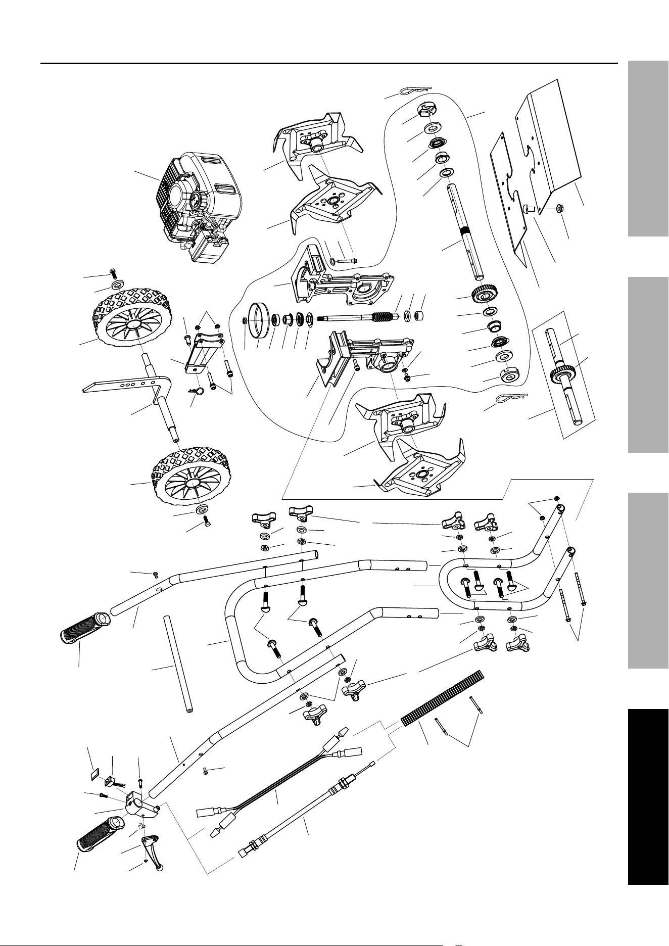
Main parts List
part Description Qty.
1 Handle Grip 2
2 Throttle Lever 1
3 Circlip Ø3.5 1
4 Torsion Spring 1
5 Throttle Bracket 1
6 Screw St4.8 x 19 1
7 Switch Assembly 1
8 Pin 1
9 Throttle Cable Assembly 1
10 Connector Wire 1
11 Right Handle 1
12 Middle Handle 1
13 Left Handle 1
14 Capscrew M8 x 45 8
15 Handle Knob M8 8
16 Tie Strap 5
17 Lower Handle 1
18 Bolt M8 x 150 2
19 Switch Cover 1
20 Flange Lock Nut M8 2
21 Screw M6 x 16 2
22 Screw M6 x 12 2
23 Washer Ø6 2
24 Wheel 2
25 Axle / Drag Bar Assembly 1
26 R-Clip Ø3 1
27 Bracket Assembly 1
28 Bolt M6 x 35 2
29 Clevis Pin 8 x 18 1
30 Flange Lock Nut M6 2
31 Nut M8 1
32 Clutch Drum 1
33 Roller Bearing 629-2rs 1
34 Worm Shaft Flange Bushing 1
35 Needle Roller Thrust Bearing 1
part Description Qty.
36 Bearing Thrust Reducer 1
37 Worm Gear Shaft 1
38 Washer 1
39 Needle Roller Bearing 1
40 Seal Washer 2
41 Bolt M6 x 10 2
42 Tine Assembly D 1
43 Tine Assembly C 1
44 Bolt M6 x 20 6
45 Left Gear Housing 1
46 Right Gear Housing 1
47 Tine Assembly B 1
48 Tine Assembly A 1
49 R-Clip 2
50 Dust Cap 2
51 Fiber Washer 2
52 Seal FB 19 x 32 x 6.5 2
53 Tine Shaft Flange Bushing 2
54 Washer 2
55 Drive Gear 1
56 Tine Shaft 1
57 Rear Tine Shield 1
58 Washer Ø8 8
59 Lock Washer Ø8 8
60 Bolt M5 x 16 2
61 Lock Nut M5 2
62 Front Tine Shield 1
63 Lock Washer Ø6 4
64 Bolt M6 x 40 4
65 Throttle Cable Housing 1
66 Combined Tine Shaft /Gear Assembly 1
67 Engine 1
68 Transmission Assembly 1
69 Cross Bar 1
Record product’s Serial Number Here:
Note: If product has no serial number, record month and year of purchase instead.
Note: Some parts are listed and shown for illustration purposes only, and are not available
individually as replacement parts. Specify UPC 193175433749 when ordering parts.
Page 23For technical questions, please call 1-888-866-5797.ITEM 58169
SAFETYSETUpOpERATIONMAINTENANCE
Main Assembly Diagram
1
2
3
5
6
7
1
4
8
9
10
11
12
13
15
14
14
15
16
17
18
20
14
21
22
23
24
25
24
23
22
21
26
27
28
29
30
57
60
61
62
65
58
59
59
58
58
59
59
58
58
59
59
58
58
59
59
14
19
67
31
32
33
34
35
36
37
38
39
41
40
42
43
44
45
47
46
48
49
50
51
52
53
54
55
56
54
53
52
51
50
49
63
64
55
56
66
68
69

Page 24 For technical questions, please call 1-888-866-5797. ITEM 58169
SAFETY SETUp OpERATION MAINTENANCE
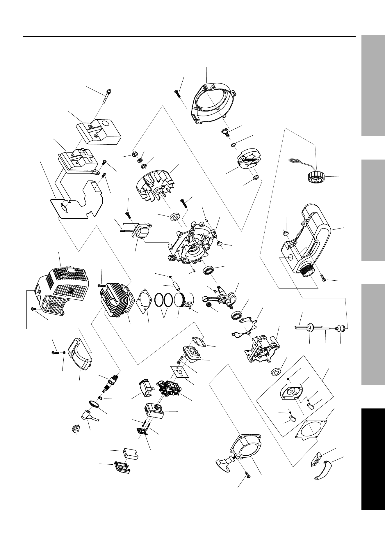
Engine parts List
part Description Qty.
1A Starter Assembly 1
2A Screw M5 x 20 7
3A Starter Gasket 1
4A Start Claw 2
5A Start Spring 2
6A Start Reel 1
7A Stop Ring 2
8A Start Reel Assembly 1
9A Oil Seal 1
10A Rear Crankcase 1
11A Crankcase Gasket 1
12A Bearing 6202/P6 2
13A Crankshaft/Connecting Rod Assembly 1
14A Key 3 x 5 x 13 1
15A Pin 4 x 10 4
16A Front Crankcase 1
17A Screw M4 x 12 1
18A Screw M5 x 30 4
19A Engine Fan 1
20A Washer Ø8 1
21A Lock Washer Ø8 1
22A Nut M8 1
23A Ignition Coil 1
24A Cord Component 1
25A Flat Washer 2
26A Expander 1
27A Wave Spring Washer 2
28A Screw Pin 2
29A Fan Cover 1
30A Oil Seal 1
31A Screw M5 x 25 6
32A Connecting Rod Bearing 1
33A Piston Pin Circlip 2
34A Piston 1
35A Piston Pin 1
36A Piston Ring 2
part Description Qty.
37A Cylinder Gasket 1
38A Cylinder 1
39A Screw M5 x 20 4
40A Engine Housing 1
41A Spark Plug 1
42A Spark Plug Spring 1
A43 Gasket 1
A44 Spark Plug Cap 1
45A Plug 1
46A Top Cover 1
47A Insulation Gasket 1
48A Muffler Gasket 1
49A Muffler Assembly 1
50A Muffler Cover 1
51A Screw M5 x 12 2
52A Screw M6 x 60-12.9 2
53A Air Intake Pipe Gasket 1
54A Air Intake Pipe 1
55A Carburetor Gasket 1
56A Carburetor Assembly 1
57A Air Cleaner Housing 1
58A Screw M5 x 50 2
59A Filter Plate 1
60A Air Filter 1
61A Air Cleaner Cover 1
62A Fuel Tank Stand 1
63A Rubber Cover 1
64A Fuel Filter 1
65A Fuel Inlet Pipe 1
66A Seal Plug 1
67A Fuel Return Pipe 1
68A Screw M5 x 16 2
69A Fuel Tank 1
70A
Fuel Tank Cap Assembly 1
71A
Rubber Washer 2
72A
Carburetor Cover 1
When ordering replacement parts from this list, the “A” suffix must be included in order to get the correct part.
Page 25For technical questions, please call 1-888-866-5797.ITEM 58169
SAFETYSETUpOpERATIONMAINTENANCE
Engine Assembly Diagram
62
63
12
12
59
61
58
60
58
9
2
1
3
54
53
55
56
31
42
43
41
45
46
27
68
64
65
10
66
67
69
26
39
19
15
34
32
11
13
33
14
16
25
18
15
38
37
36
35
33
23
30
22
2
24
31
28
29
51
48
2
40
52
49
44
20
21
71
50
17
47
57
51
70
71
4
5
4
5
6
7
8
72

Page 26 For technical questions, please call 1-888-866-5797. ITEM 58169
SAFETY SETUp OpERATION MAINTENANCE
Warranties
Limited 90 Day Warranty (Retail)
Harbor Freight Tools Co. makes every effort to assure that its products meet high quality and durability standards,
and warrants to the original purchaser that this product is free from defects in materials and workmanship for the
period of 90 days from the date of purchase. This warranty does not apply to damage due directly or indirectly,
to misuse, abuse, negligence or accidents, repairs or alterations outside our facilities, criminal activity, improper
installation, normal wear and tear, or to lack of maintenance. We shall in no event be liable for death, injuries
to persons or property, or for incidental, contingent, special or consequential damages arising from the use of
our product. Some states do not allow the exclusion or limitation of incidental or consequential damages, so
the above limitation of exclusion may not apply to you. THIS WARRANTY IS EXPRESSLY IN LIEU OF ALL
OTHER WARRANTIES, EXPRESS OR IMPLIED, INCLUDING THE WARRANTIES OF MERCHANTABILITY
AND FITNESS, EXCEPT FOR THE EMISSIONS CONTROL SYSTEM WARRANTY BELOW.
To take advantage of this warranty, the product or part must be returned to us with transportation charges prepaid.
Proof of purchase date and an explanation of the complaint must accompany the merchandise. If our
inspection verifies the defect, we will either repair or replace the product at our election or we may elect to
refund the purchase price if we cannot readily and quickly provide you with a replacement. We will return
repaired products at our expense, but if we determine there is no defect, or that the defect resulted from
causes not within the scope of our warranty, then you must bear the cost of returning the product.
This warranty gives you specific legal rights and you may also have other rights which vary from state to state.
Emissions Control System Warranty
Harbor Freight Tools (HFT) is pleased to explain the emissions control system warranty on your Small Off-Road
Engine produced after January 1, [Model Year] (engine), in addition to the Retail Warranty above. HFT warrants
that the emissions control system on your engine is designed, built, and equipped so that it conforms to the United
States Environmental Protections Agency’s (EPA) emissions requirements in effect at the time of manufacture.
HFT also warrants that the emissions control system on your engine will be free from defects in material and
workmanship for two (2) years, provided there has been no improper maintenance, misuse, or abuse of your engine.
Your emissions control system may include parts such as the carburetor or fuel-injection system, and the
ignition system. Also included may be hoses, belts, connectors and other emissions-related assemblies.
WHAT WE WILL DO
Where a warrantable condition exists, HFT will repair or replace, at our option, any emissions-related part on
your engine if it becomes defective, malfunctions, or otherwise fails to conform with this warranty under normal use
and service during the two (2) year term of this warranty at no cost to you, including diagnosis, parts and labor.
This warranty applies to the original purchaser and any subsequent owner within the two year warranty period.

Page 27For technical questions, please call 1-888-866-5797.ITEM 58169
SAFETYSETUpOpERATIONMAINTENANCE
WHAT IS COVERED?
The following parts are examples of components of the emissions control system
and are covered by this two (2) year warranty. For a full list of emissions control
components covered by this warranty, please see 40 CFR §1068, Appendix I.
1. Fuel Metering System
a. Carburetor and its internal parts.
b. Fuel pump (if so equipped).
c. Cold start enrichment system.
2. Air Induction System
a. Intake pipe/manifold.
b. Air cleaner.
3. Ignition System
a. Spark plug.
b. Magneto ignition system.
4. Catalyst System (if so equipped)
a. Exhaust pipe stud.
b. Muffler.
c. Catalytic converter (if so equipped).
5. Miscellaneous Items Used in Above Systems
a. Vacuum, temperature and
time sensitive valves and switches.
b. Hoses, belts, connectors, and assemblies.
This warranty does not cover normal maintenance services or replacement
of maintenance items such as filters, oils, or spark plugs.
WHAT YOU MUST DO TO OBTAIN WARRANTY SERVICE
As the engine owner, you are responsible for the performance of the required maintenance
listed in your Owner’s Manual. HFT may deny you warranty coverage if your engine or a
part has failed due to abuse (including failure to follow the fuel use instructions contained
in this manual), neglect, improper maintenance, or unapproved modifications.
In order to obtain warranty repair or replacement, you may either (a) contact HFT product support at
1-888-866-5797 or [email protected]; or (b) bring the to your nearest Harbor Freight Tools
retail store. When going to the retail store or contacting product support, you must indicate the specific
emissions control part or defect that you are claiming and the date this was originally purchased. The nearest
Harbor Freight Tools retail store can be found on the internet at http://www.harborfreight.com.

26677 Agoura Road • Calabasas, CA 91302 • 1-888-866-5797
pLEASE READ THE FOLLOWING CAREFULLY
THE MANUFACTURER AND/OR DISTRIBUTOR HAS PROVIDED THE PARTS LIST AND ASSEMBLY DIAGRAM
IN THIS MANUAL AS A REFERENCE TOOL ONLY. NEITHER THE MANUFACTURER OR DISTRIBUTOR
MAKES ANY REPRESENTATION OR WARRANTY OF ANY KIND TO THE BUYER THAT HE OR SHE IS
QUALIFIED TO MAKE ANY REPAIRS TO THE PRODUCT, OR THAT HE OR SHE IS QUALIFIED TO REPLACE
ANY PARTS OF THE PRODUCT. IN FACT, THE MANUFACTURER AND/OR DISTRIBUTOR EXPRESSLY
STATES THAT ALL REPAIRS AND PARTS REPLACEMENTS SHOULD BE UNDERTAKEN BY CERTIFIED AND
LICENSED TECHNICIANS, AND NOT BY THE BUYER. THE BUYER ASSUMES ALL RISK AND LIABILITY
ARISING OUT OF HIS OR HER REPAIRS TO THE ORIGINAL PRODUCT OR REPLACEMENT PARTS
THERETO, OR ARISING OUT OF HIS OR HER INSTALLATION OF REPLACEMENT PARTS THERETO.