
Product Name and Model Number User
Manual
Page | 1 Copyright©2020 ZKTECO CO., LTD. All rights reserved.
Thank you for choosing our product. Please read the instructions carefully
before operation. Follow these instructions to ensure that the product is
functioning properly. The images shown in this manual are for illustrative
purposes only.
For further details, please visit our Company’s website
www.zkteco.com
.
User Manual
InBioPC Series
Date: May 2025
Doc Version: 1.0
English

InBioPC Series User Manual
Page | 1 Copyright©2025 ZKTECO CO., LTD. All rights reserved.
Copyright © 2025 ZKTECO CO., LTD. All rights reserved.
Without the prior written consent of ZKTeco, no portion of this manual can be copied or forwarded in any
way or form. All parts of this manual belong to ZKTeco and its subsidiaries (hereinafter the "Company" or
"ZKTeco").
Trademark
is a registered trademark of ZKTeco. Other trademarks involved in this manual are owned by
their respective owners.
Disclaimer
This manual contains information on the operation and maintenance of the ZKTeco equipment. The
copyright in all the documents, drawings, etc. in relation to the ZKTeco supplied equipment vests in and is
the property of ZKTeco. The contents hereof should not be used or shared by the receiver with any third
party without express written permission of ZKTeco.
The contents of this manual must be read as a whole before starting the operation and maintenance of the
supplied equipment. If any of the content(s) of the manual seems unclear or incomplete, please contact
ZKTeco before starting the operation and maintenance of the said equipment.
It is an essential pre-requisite for the satisfactory operation and maintenance that the operating and
maintenance personnel are fully familiar with the design and that the said personnel have received
thorough training in operating and maintaining the machine/unit/equipment. It is further essential for the
safe operation of the machine/unit/equipment that personnel has read, understood and followed the
safety instructions contained in the manual.
In case of any conflict between terms and conditions of this manual and the contract specifications,
drawings, instruction sheets or any other contract-related documents, the contract conditions/documents
shall prevail. The contract specific conditions/documents shall apply in priority.
ZKTeco offers no warranty, guarantee or representation regarding the completeness of any information
contained in this manual or any of the amendments made thereto. ZKTeco does not extend the warranty
of any kind, including, without limitation, any warranty of design, merchantability or fitness for a particular
purpose.
ZKTeco does not assume responsibility for any errors or omissions in the information or documents which
are referenced by or linked to this manual. The entire risk as to the results and performance obtained from
using the information is assumed by the user.
ZKTeco in no event shall be liable to the user or any third party for any incidental, consequential, indirect,
special, or exemplary damages, including, without limitation, loss of business, loss of profits, business
interruption, loss of business information or any pecuniary loss, arising out of, in connection with, or

InBioPC Series User Manual
Page | 2 Copyright©2025 ZKTECO CO., LTD. All rights reserved.
relating to the use of the information contained in or referenced by this manual, even if ZKTeco has been
advised of the possibility of such damages.
This manual and the information contained therein may include technical, other inaccuracies or
typographical errors. ZKTeco periodically changes the information herein which will be incorporated into
new additions/amendments to the manual. ZKTeco reserves the right to add, delete, amend or modify the
information contained in the manual from time to time in the form of circulars, letters, notes, etc. for better
operation and safety of the machine/unit/equipment. The said additions or amendments are meant for
improvement /better operations of the machine/unit/equipment and such amendments shall not give any
right to claim any compensation or damages under any circumstances.
ZKTeco shall in no way be responsible (i) in case the machine/unit/equipment malfunctions due to any
non-compliance of the instructions contained in this manual (ii) in case of operation of the
machine/unit/equipment beyond the rate limits (iii) in case of operation of the machine and equipment in
conditions different from the prescribed conditions of the manual.
The product will be updated from time to time without prior notice. The latest operation procedures and
relevant documents are available on http://www.zkteco.com
If there is any issue related to the product, please contact us.
ZKTeco Headquarters
Address ZKTeco Industrial Park, No. 32, Industrial Road,
Tangxia Town, Dongguan, China.
Phone +86 769 - 82109991
Fax +86 755 - 89602394
For business related queries, please write to us at: [email protected]m
.
To know more about our global branches, visit www.zkteco.com.

InBioPC Series User Manual
Page | 3 Copyright©2025 ZKTECO CO., LTD. All rights reserved.
About the Company
ZKTeco is one of the world’s largest manufacturer of RFID and Biometric (Fingerprint, Facial, Finger-vein)
readers. Product offerings include Access Control readers and panels, Near & Far-range Facial Recognition
Cameras, Elevator/floor access controllers, Turnstiles, License Plate Recognition (LPR) gate controllers and
Consumer products including battery-operated fingerprint and face-reader Door Locks. Our security
solutions are multi-lingual and localized in over 18 different languages. At the ZKTeco state-of-the-art
700,000 square foot ISO9001-certified manufacturing facility, we control manufacturing, product design,
component assembly, and logistics/shipping, all under one roof.
The founders of ZKTeco have been determined for independent research and development of biometric
verification procedures and the productization of biometric verification SDK, which was initially widely
applied in PC security and identity authentication fields. With the continuous enhancement of the
development and plenty of market applications, the team has gradually constructed an identity
authentication ecosystem and smart security ecosystem, which are based on biometric verification
techniques. With years of experience in the industrialization of biometric verifications, ZKTeco was
officially established in 2007 and now has been one of the globally leading enterprises in the biometric
verification industry owning various patents and being selected as the National High-tech Enterprise for 6
consecutive years. Its products are protected by intellectual property rights.
About the Manual
This manual introduces the operations of the InBioPC400/InBioPC800.
All figures displayed are for illustration purposes only. Figures in this manual may not be exactly consistent
with the actual products.
Features and parameters with
★ are not available in all devices.
InBioPC Series User Manual
Page | 4 Copyright©2025 ZKTECO CO., LTD. All rights reserved.
Document Conventions
Conventions used in this manual are listed below:
GUI Conventions
For Software
Convention Description
Bold font Used to identify software interface names e.g. OK, Confirm, Cancel.
>
Multi-level menus are separated by these brackets. For example, File > Create >
Folder.
For Device
Convention Description
< >
Button or key names for devices. For example, press <OK>.
[ ]
Window names, menu items, data table, and field names are inside square
brackets. For example, pop up the [New User] window.
/
Multi-
level menus are separated by forwarding slashes. For example,
[File/Create/Folder].
Symbols
Convention Description
This represents a note that needs to pay more attention to.
The general information which helps in performing the operations faster.
The information which is significant.
Care taken to avoid danger or mistakes.
The statement or event that warns of something or that serves as a cautionary
example.

InBioPC Series User Manual
Page | 5 Copyright©2025 ZKTECO CO., LTD. All rights reserved.
Table of Contents
1 SAFETY INSTRUCTIONS ....................................................................................................................... 7
1.1 Important Notes ........................................................................................................................................................................................ 7
1.2 Installation Cautions ................................................................................................................................................................................ 8
2 OVERVIEW .......................................................................................................................................... 10
2.1 Features ...................................................................................................................................................................................................... 11
2.2 Technical Specifications ....................................................................................................................................................................... 12
3 CONTROLLER TERMINAL DESCRIPTION ........................................................................................... 14
3.1 Description of the LEDs on the Controller Panel ........................................................................................................................ 14
3.2 Appearance and System Components ........................................................................................................................................... 16
3.3 Wire Selection Instructions ................................................................................................................................................................. 18
4 DE10 ................................................................................................................................................... 19
4.1 Wire Selection Instructions ................................................................................................................................................................. 21
5 INSTALLATION ................................................................................................................................... 22
6 ACCESS CONTROLLER WIRING ......................................................................................................... 24
6.1 Power Supply Connection ................................................................................................................................................................... 24
6.2 Computer Connection .......................................................................................................................................................................... 24
6.3 DE10 Connection .................................................................................................................................................................................... 25
6.4 Auxiliary Outputs Connection ........................................................................................................................................................... 25
6.5 Auxiliary Inputs Connection ............................................................................................................................................................... 25
6.6 Alarm Connection ................................................................................................................................................................................... 26
6.7 Fire Protection Input Interface Connection .................................................................................................................................. 27
7 DE10 WIRING ..................................................................................................................................... 28
7.1 Reader Connection ................................................................................................................................................................................. 28
7.1.1 Wiegand Reader Connection ................................................................................................................................................................... 28
7.1.2 Connecting the RS485 Reader ................................................................................................................................................................. 28
7.2 Connecting the Sensor ......................................................................................................................................................................... 29
7.3 Connecting the Exit Button ................................................................................................................................................................ 29
7.4 Auxiliary Input Connection ................................................................................................................................................................. 30
7.5 Auxiliary Output Connection ............................................................................................................................................................. 31
7.6 Tamper Switch Connection ................................................................................................................................................................ 31
7.7 Lock Connection ..................................................................................................................................................................................... 31
8 ACCESS CONTROL SYSTEM ............................................................................................................... 33
9 LOGIN TO WEBSERVER ...................................................................................................................... 34
9.1 PC .................................................................................................................................................................................................................. 34
9.2 Phone........................................................................................................................................................................................................... 38
10 ZKBIO CVSECURITY INTEGRATION ............................................................................................... 39

InBioPC Series User Manual
Page | 6 Copyright©2025 ZKTECO CO., LTD. All rights reserved.
10.1 Add the Device ........................................................................................................................................................................................ 39
10.2 Door ............................................................................................................................................................................................................. 41
10.3 Reader ......................................................................................................................................................................................................... 41
10.4 Auxiliary Input .......................................................................................................................................................................................... 42
10.5 Auxiliary Output ...................................................................................................................................................................................... 43
10.6 Event Type ................................................................................................................................................................................................. 44
10.7 Real-Time Monitoring ........................................................................................................................................................................... 45
10.8 Alarm Monitoring ................................................................................................................................................................................... 45
10.9 Interlock ...................................................................................................................................................................................................... 46
10.10 Linkage ........................................................................................................................................................................................................ 46
10.11 Anti-Passback ........................................................................................................................................................................................... 47
APPENDIX 1 ............................................................................................................................................... 48
Privacy Policy ........................................................................................................................................................................................................ 48
Eco-friendly Operation ..................................................................................................................................................................................... 51

InBioPC Series User Manual
Page | 7 Copyright©2025 ZKTECO CO., LTD. All rights reserved.
1 Safety Instructions
1.1 Important Notes
1. Before operating the device, please read and strictly follow all security and operation instructions.
Please keep the instructions in good condition for future reference.
2. Please use the accessories recommended by the manufacturer or delivered together with the product.
Any other related product is not recommended to be used as the alarm or monitoring system
(cameras, infrared detectors, smoke detectors, etc.). The alarm or monitoring system should comply
with the local applicable fire-prevention and security standards.
3. Do not place this device on any unstable table, tripod mount, supterminal or base to prevent the
device from falling and damages, and more undesirably causing severe personal injuries. Therefore, it
is important to install the device as instructed by the manufacturer.
4. All peripheral devices must be grounded.
5. No external connection wires can be exposed. All connections and idle wire ends must be wrapped
with insulating tapes to prevent accidental contact with exposed wires from damaging the device.
6. Do not attempt to carry out unauthorized repair of the device. Disassembly or detachment is likely to
cause electric shock or other physical problems. All repair should be done by qualified repair
personnel.
7. In any of the following cases, disconnect the power supply from the device first and notify qualified
repair personnel for repair:
The power cord or connector is damaged;
Liquid leaks into or any objects fall into the device;
The device has got wet or exposed to bad weather (rain, snow, etc.);
If the device cannot work normally even though it is operated as instructed;
The device falls down or its performance changes obviously.
8. If it is necessary to replace a component, the repair personnel must use only the substitutes specified
by the manufacturer.
9. After the device is repaired, the repair personnel needs to conduct security inspection to ensure the
device works normally.
10. Operate the device with only the type of power supply indicated on the label. Contact the operator
for any uncertainty about the type of power supply.

InBioPC Series User Manual
Page | 8 Copyright©2025 ZKTECO CO., LTD. All rights reserved.
1.2 Installation Cautions
1. Network cable selection must be Super Category 5 network cable oxygen-free copper material above
specifications, core nominal diameter 0.5mm. 100 meters of single wire resistance is less than 10 ohms.
Try to choose a higher specification network cable (such as Category 6 oxygen-free copper material),
reserve enough margin to meet the maximum load requirements.
2. All wiring must be sleeved, optional PVC pipe and galvanized pipe, to avoid mice bite off the line
caused by failure. Although the controller has a good anti-static, lightning, leakage-proof design,
please make sure that the controller chassis and AC ground connection is perfect, and the AC ground
is truly grounded.
3. It is recommended not to plug and unplug connection terminals frequently when the system is
energized. Be sure to unplug the connection terminals before starting any relevant welding job.
4. Do not detach or replace any control panel chip without permission because unprofessional
operation may cause damage to the control panel.
5. It is recommended not to connect any other auxiliary devices without permission. All non-routine
operations must be confirmed with our engineers in advance.
6. A control panel should not share one power socket with any other large-current devices.
7. It is preferable to install card readers and buttons at a height of 55 inches to 59 inches (1.4m to 1.5m)
above the ground, subject to proper adjustment according to customers’ usual practice.
8. The device is recommended to be installed in an easy-to-maintain location such as a server room or
weak well.
9. The exposed part of any connection terminal is strongly recommended not be longer than 0.16 inches
(4mm). Professional clamping tools may be used to avoid short-circuit or communication failure
resulting from accidental contact with excessive exposed wires.
10. If you need to keep a record of access control events, periodically export the data from the controller.
11. Prepared countermeasures against unexpected power failure, like selecting power supply with UPS.
Violation of any of the following cautions may result in personal injury or device
malfunctions. We assume no responsibility for any damage caused by mishandling that is
beyond normal usage defined in this product manual.
Before installation, switch off the external circuit (that supplies power to the system).
Before connecting the device to power supply, ensure the output voltage is within the
specified range.
Never connect the product to the power before completion of installation.

InBioPC Series User Manual
Page | 9 Copyright©2025 ZKTECO CO., LTD. All rights reserved.
12. In order to prevent the self-induced electromotive force generated by the electric lock at the moment
of switching on and off from affecting the access control system, it is necessary to connect a diode in
parallel with the electric lock (please use the FR107 diode supplied with the system) to release the
self-induced electromotive force generated at the moment of switching on and off of the electric lock
during the wiring of the access control system on-site application.
13. It is recommended to use the power supply delivered with the system as the control panel power
supply.
14. In a place with strong magnetic interference, galvanized steel pipes or shielded cables are
recommended, and proper grounding is required.
InBioPC Series User Manual
Page | 10 Copyright©2025 ZKTECO CO., LTD. All rights reserved.
2 Overview
The InBioPC Main Controller is the pinnacle of access control technology, offering seamless integration
with DE-10 Door Units and supporting up to 4/8 access points. Engineered for high-speed TCP/IP
communication, it ensures efficient and reliable data transfer. The onboard webserver, accessible via Wi-Fi,
simplifies system configuration, providing unparalleled ease of use. Compliant with power over Ethernet
(PoE IEEE802.3 and PSE@30W) standards, the InBioPC can power up to 4/8 DE-10 Door Units, delivering
both performance and convenience.
This advanced controller boasts a suite of sophisticated access control functions and supports dynamic QR
code generation through the ZKBio CVSecurity Mobile Applications, enhancing security and user
experience. With support for InBioPC offers versatile authentication methods to meet diverse security
needs. Its compatibility with the ZKTeco A&C push protocol ensures seamless communication with ZKBio
CVSecurity software.
Operating within a wide voltage input range of AC 100V~240V, the InBioPC is designed for global
deployment. It incorporates high-security data encryption methods, including HTTP / HTTPS, SSH, AES256,
and TLS 2.0, safeguarding sensitive information. Supporting both Wiegand readers (formats: W26 / W34 /
W66) and RS485 card readers (protocol: ZKTeco RS-485), it provides flexible connectivity options.
Furthermore, the InBioPC is designed in a standard 1U server rack size, ensuring compatibility with
standard server rack installations. This makes it an ideal choice for organizations looking to deploy a robust,
scalable, and secure access control solution.
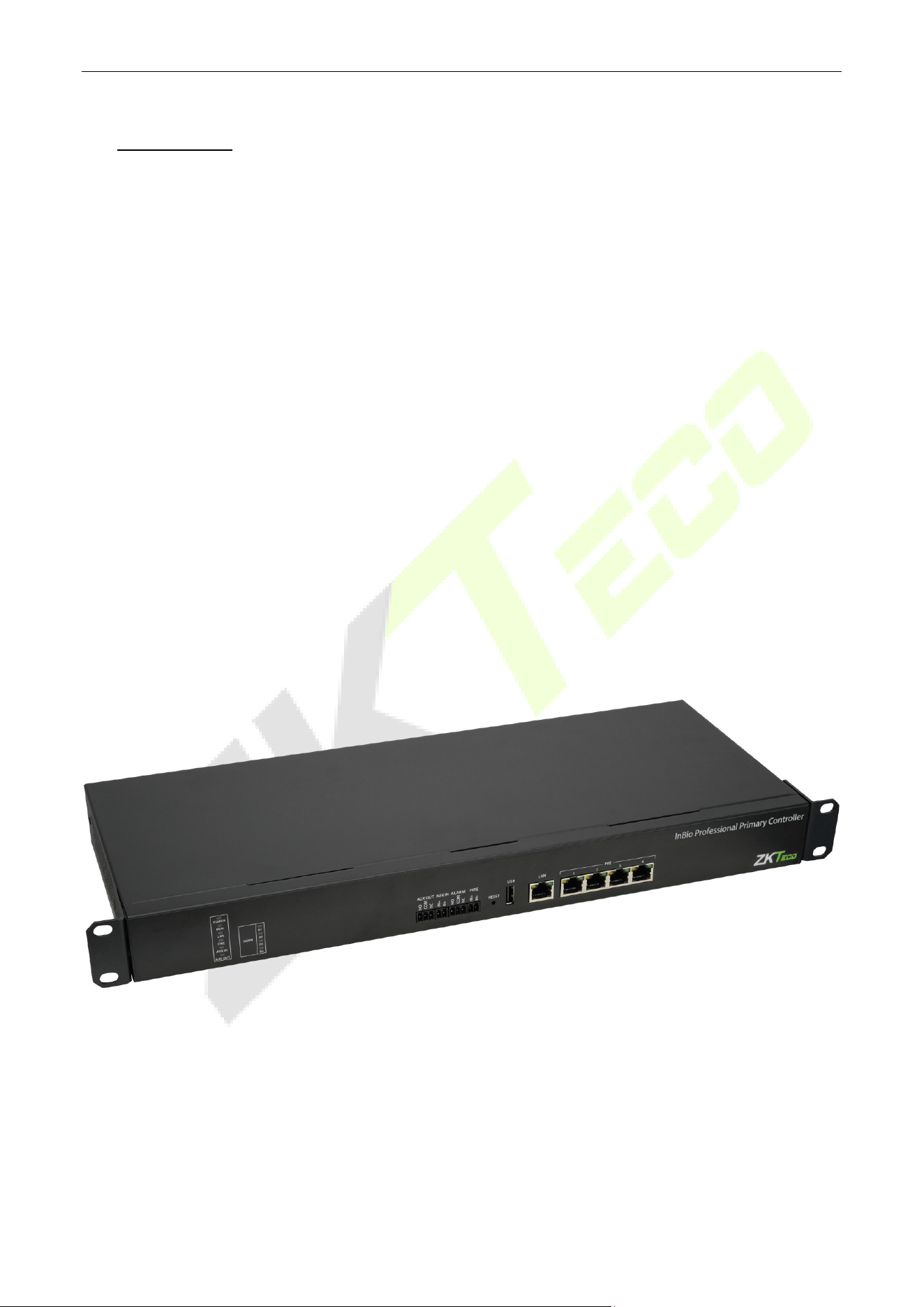
InBioPC-400
InBioPC Series User Manual
Page | 11 Copyright©2025 ZKTECO CO., LTD. All rights reserved.
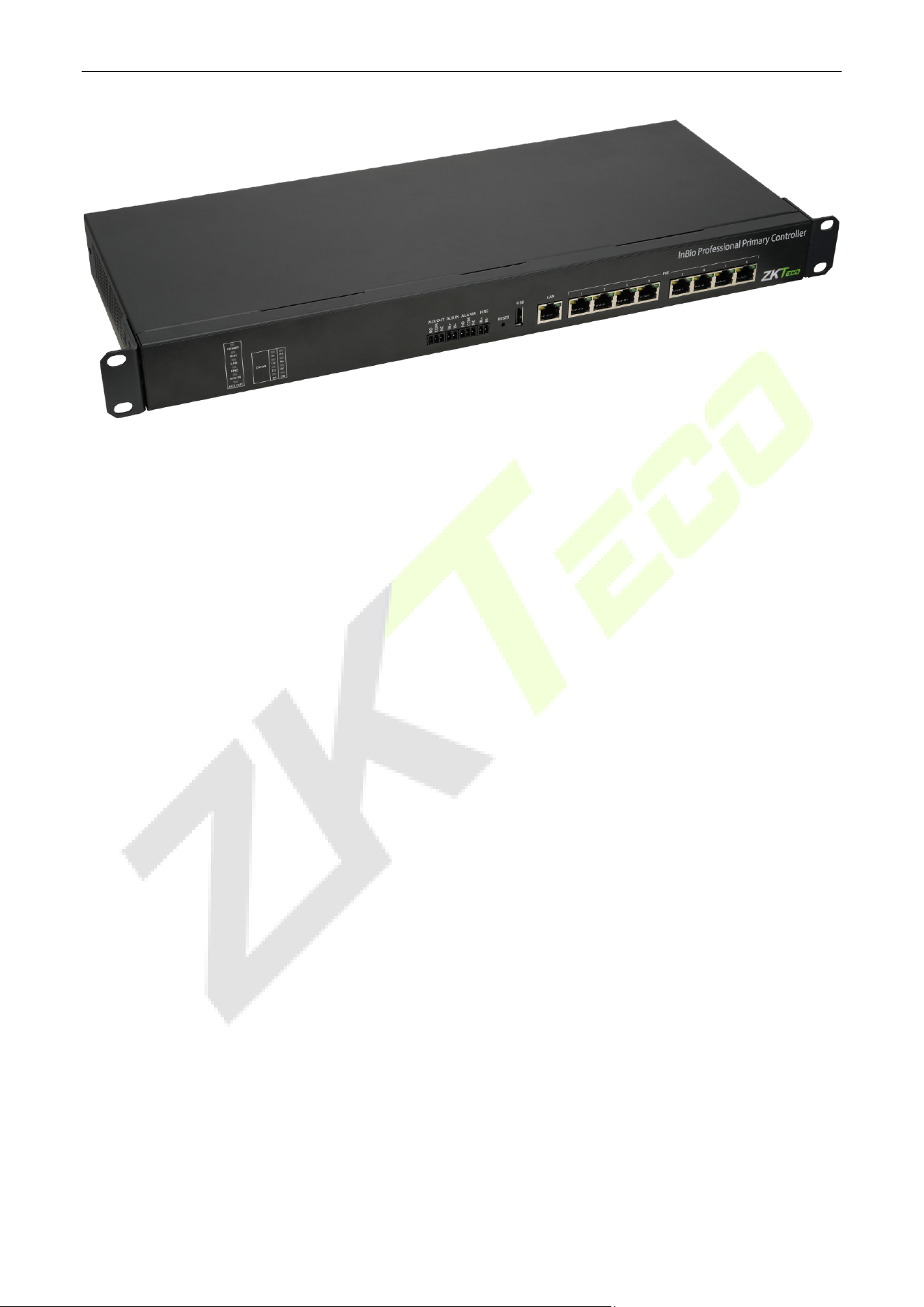
InBioPC-800
2.1 Features
Seamlessly integrates with DE-10 Door Units, supporting up to 4/8 access points.
Supports high-speed TCP/IP communication for efficient data transfer.
An embedded onboard webserver is available for system configuration and is accessible via Wi-Fi.
Complies with IEEE 802.3 at PoE and PSE@30W standards to power up to 4/8 DE-10 Door Units.
Equipped with advanced access control functions for enhanced security.
Supports dynamic QR code generation with ZKBio CVSecurity Mobile Applications.
Supports multiple credential options, including biometrics, RFID, and password.
Compatible with the A&C push protocol.
Operates with a wide voltage input range of AC 100V~240V.
Supports high-security data encryption methods such as HTTP / HTTPS, SSH, AES256, and TLS 2.0.
Supports Wiegand readers (formats: W26 / W34 / W66) and RS485 card readers (protocol: ZKTeco RS-
485)
Designed in standard 1U server rack size to be compatible with standard server rack installation.

InBioPC Series User Manual
Page | 12 Copyright©2025 ZKTECO CO., LTD. All rights reserved.
2.2 Technical Specifications
Model InBioPC-400 InBioPC-800
Onboard Visual Indicator
POWER (RED): ON - Power Normal, OFF - No Power;
RUN (GREEN): Slow Flashing - Normal Use, Flashing - Host not connected,
OFF - No Power;
LAN (GREEN): Steady on - No data interaction, Flashing - Data in
Interaction, OFF - Network Connection Abnormal;
FIRE (RED): Flashing - In Fire Alarm, OFF - No Fire Alarm;
AUX IN (RED): Flashing - In Alarm, OFF - No Alarm;
DOOR (GREEN): Steady ON - Door Closed, Flashing - Door Open, OFF - Lock
Offline
Operation System Linux
Hardware
CPU: Dual Cor[email protected]
RAM: 128MB; ROM: 256MB
Authentication method Card / Password / Fingerprint / QR code
Access Point Capacity
Onboard Access Point: 0
Max Access Point: 4 (with DE10
Door Unit)
Onboard Access Point: 0
Max Access Point: 8 (with DE10
Door Unit)
Fingerprint Template
Capacity
4,000 (1:N) (Standard)
Card Capacity 40,000 (1:N) (Standard)
QR Code Capacity 40,000 (QR Code and Dynamic QR Code)
User Capacity 40,000
Transaction Capacity 200,000 (Standard)
Number of Inputs 1*AUX Inputs, 1*FIRE

InBioPC Series User Manual
Page | 13 Copyright©2025 ZKTECO CO., LTD. All rights reserved.
Number of Outputs
1*Form C Relay for Aux Output
1*Form C Relay for Alarm
Supported Biometric
Algorithm
ZKFingerprint V10.0
Max. Card Length Supports up to 66 bits Card Length
QR Code Dynamic QR codes on the ZKBio CVSecurity mobile application QR code
Communication
TCP/IP*1 Wi-Fi (IEEE802.11b/g/n/, 1T1R @ 2.4 GHz) (Wi-
Fi only for
webserver access)
Standard Functions
Webserver, Up to 14-digit User ID, Access Levels, Access Groups, Holidays,
Anti-passback, Anti-
tailgating, Linkage, Global Linkage, Multiple
Verification Methods
Verification Speed less than 0.3 sec (Fingerprint)
Power Supply
Power Input: AC 100V~240V
Power Out
put: POE (IEEE802.3at
PSE@30W output) *4
Power Input: AC 100V~240V
Power Out
put: POE (IEEE802.3at
PSE@30W output) *8
Operating Temperature 0°C to 45°C
Operating Humidity 20% to 80% RH (Non-condensing)
Dimensions
440mm*180mm*45mm (L*W*H)
(Standard 1U Server Rack Size)
440mm*180mm*45mm (L*W*H)
(Standard 1U Server Rack Size)
Gross Weight 2.725Kg 2.825Kg
Net Weight 2.079Kg 2.179Kg
Supported Software ZKBio CVSecurity
Installation
Supported Rack-mount (Compatabile with Standard Server Rack) / Wall-
mount / Desktop
Housing Material SGCC
InBioPC Series User Manual
Page | 14 Copyright©2025 ZKTECO CO., LTD. All rights reserved.
Certifications ISO14001, ISO9001, CE, FCC, RoHS
3 Controller Terminal Description
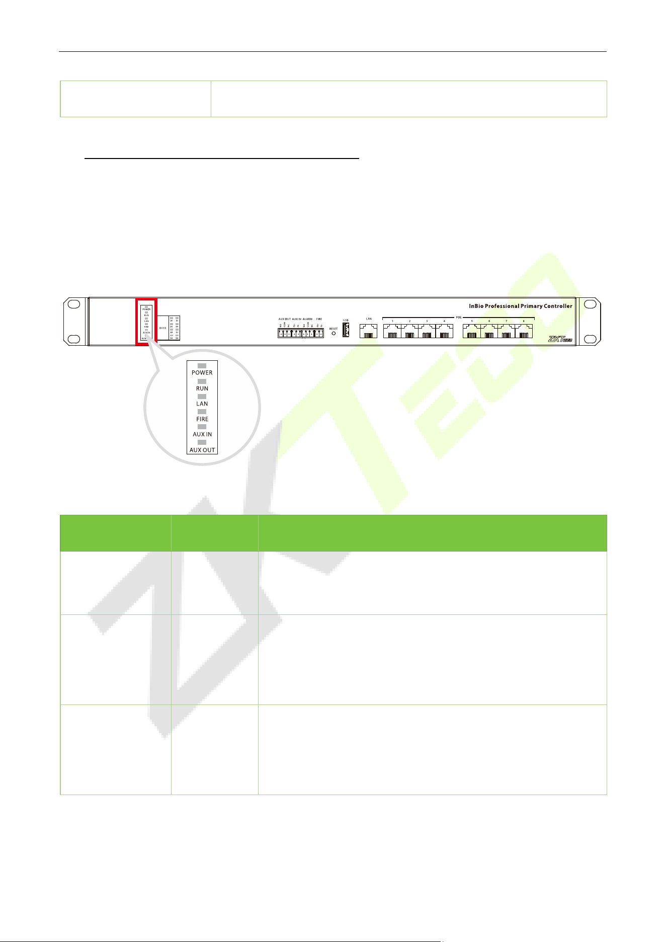
3.1 Description of the LEDs on the Controller Panel
When the InBioPC series controller is powered on, under normal conditions, the POWER indicator (red) is
always on, the RUN indicator (green) flashes (indicating a normal system), and none of the other lights are
on. However, in the following cases:
Menu Color Description
POWER Red
Red light always on (power supply normal power supply)
Red light off (abnormal power supply)
RUN Green
Green light flashes slowly (system normal)
Green light flashes fast (firmware upgrade in progress)
Green light off (dead)
LAN Green
Green light always on (no data interaction)
Green light flashing (with data interaction)
Green light off (abnormal network connection)
InBioPC Series User Manual
Page | 15 Copyright©2025 ZKTECO CO., LTD. All rights reserved.
FIRE Red
Red light flashing (with access to fire protection and receiving a
short circuit signal)
Red light off (have access to fire protection but not receiving
short circuit signal)
AUX IN Red
Red light blinking (there is access to the auxiliary input and
receive a signal)
Red light off (auxiliary input accessed but no signal received)
AUX OUT Red
Red light blinking (there is access to the auxiliary output and
output signal)
Red light is off (auxiliary output is connected, but no signal is
received)
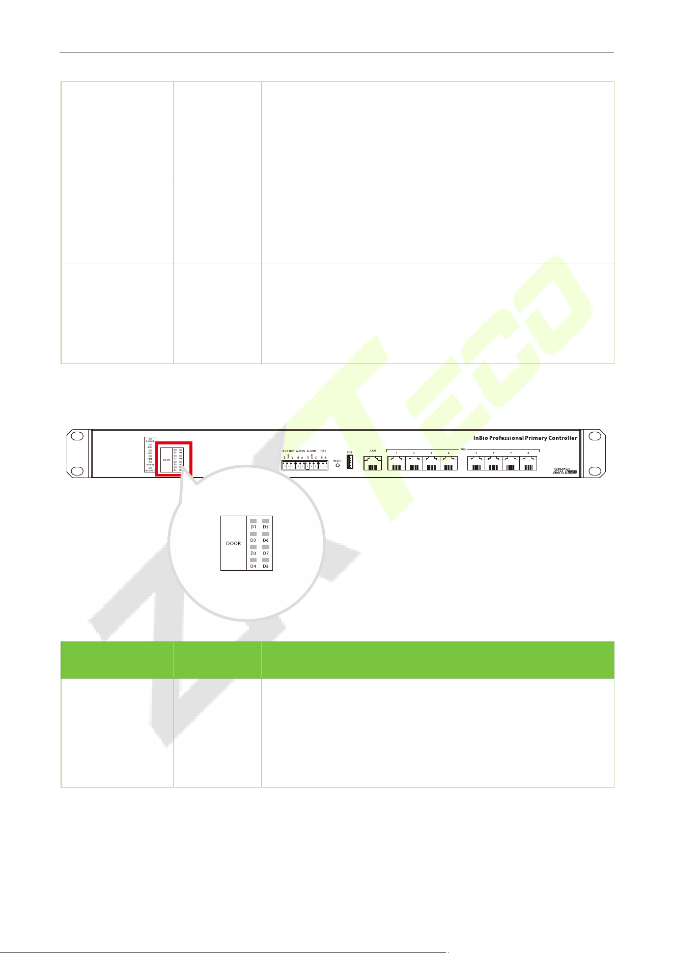
The indicators for the access control terminals are as follows:
Menu Color Description
DOOR Green
Green light always on (online status door sensor
off/no door
sensor)
Green light flashing (online status door sensor open)
Green light off (offline status)
InBioPC Series User Manual
Page | 16 Copyright©2025 ZKTECO CO., LTD. All rights reserved.
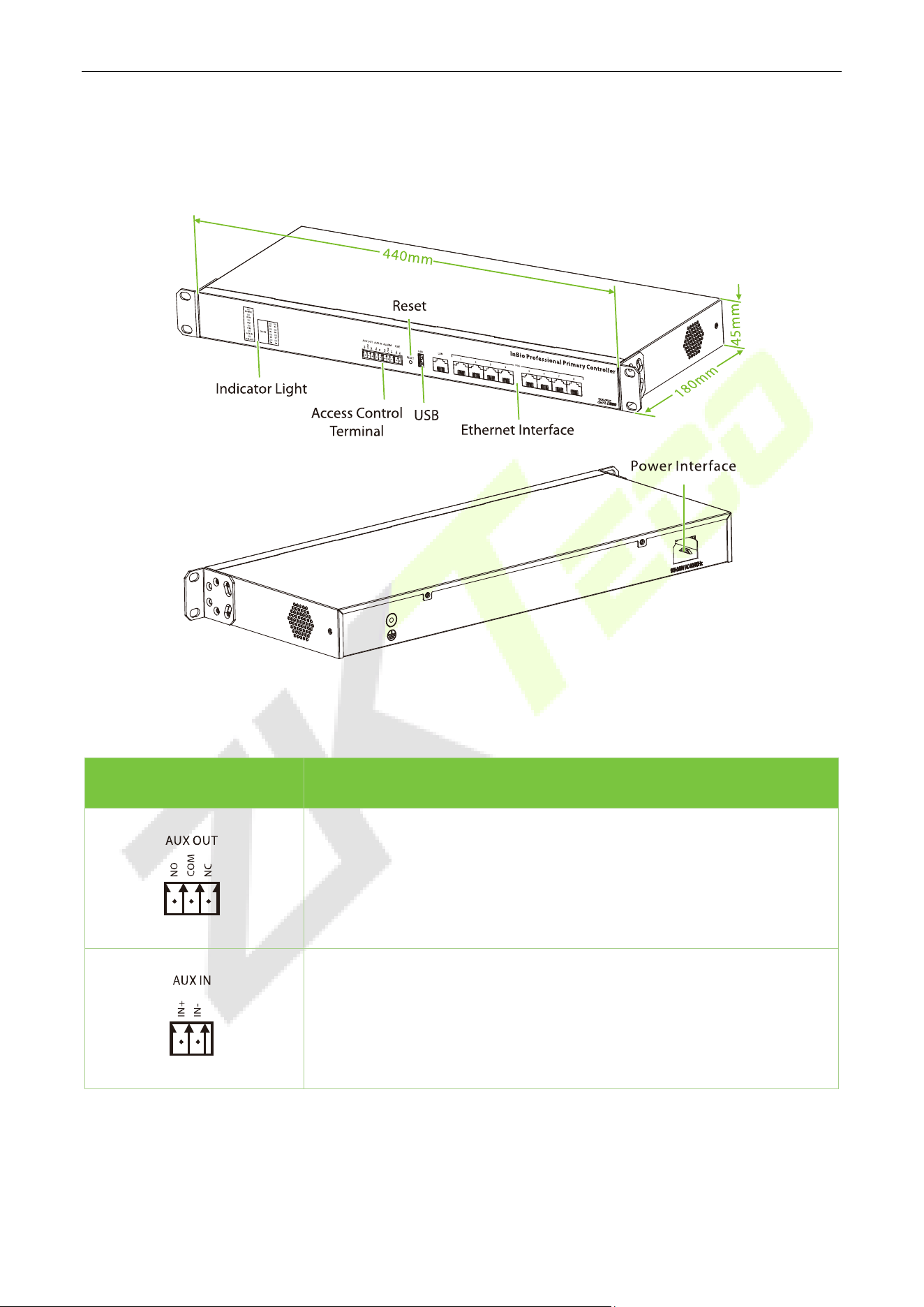
3.2 Appearance and System Components
Access Control Terminal:
No. Description
Auxiliary output, can be connected to alarm or doorbell, etc.
Maximum switching voltage of the
contact is 24VDC, maximum
switching current is 1A.
Auxiliary input, can be connected to infrared human body sensing
detector, fire alarm or smoke detector, etc.
Maximum input voltage 12VDC.
InBioPC Series User Manual
Page | 17 Copyright©2025 ZKTECO CO., LTD. All rights reserved.
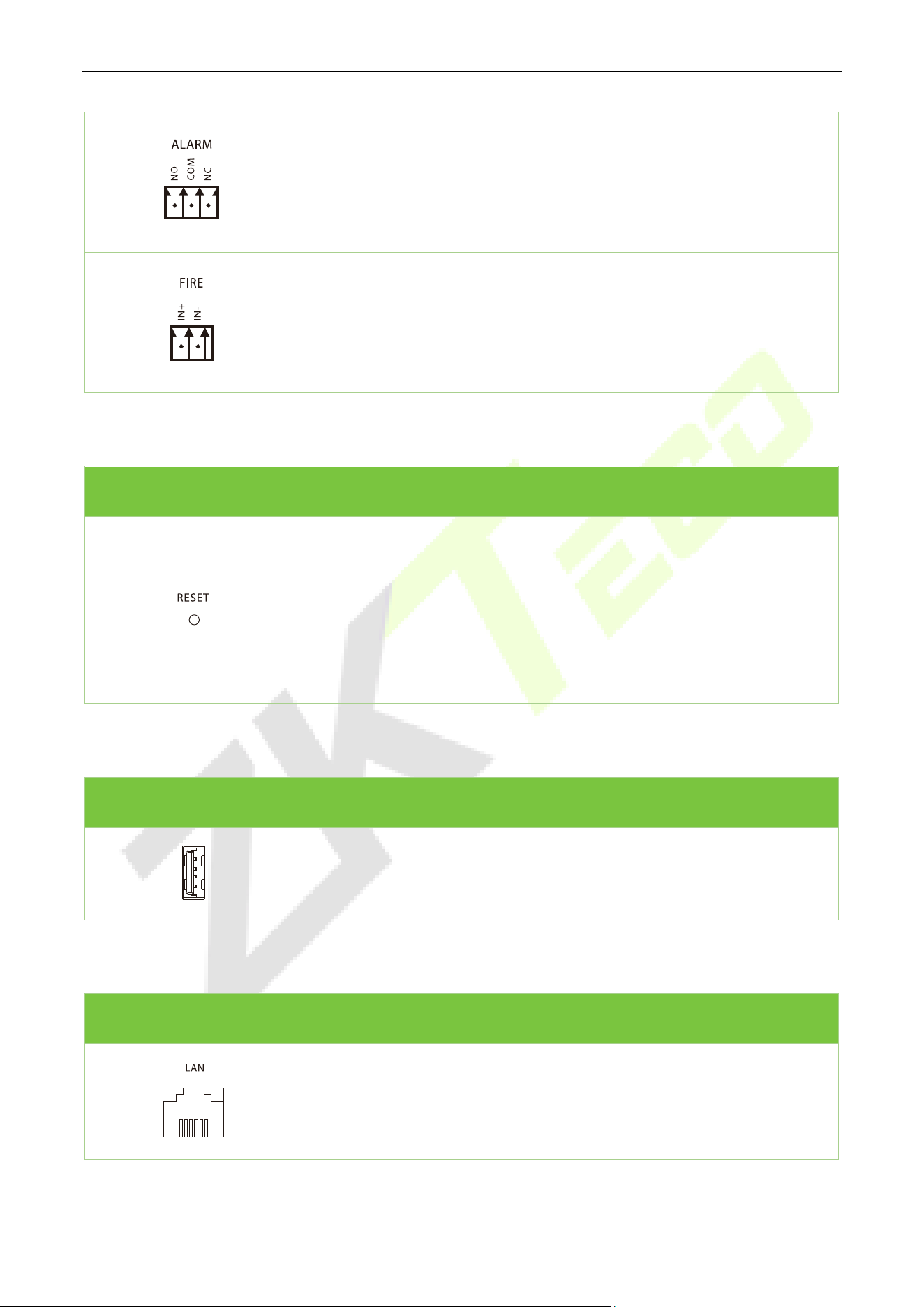
Alarm output for alarm connection
Maximum switching voltage of the contact is 24VDC, maximum
switching current is 1A.
Fire input, external fire button, trigger the fire button, all doors forced
normally open
Maximum input voltage 12VDC.
Reset:
No. Description
Use a pickup pin to poke the device long:
0 < Firmware Upgrade ≤
5s (Insert the USB flash drive with
firmware before poking the device with the pickup pin for a long
time)
5s<Reboot≤10s
10s<Restore Factory Settings
USB:
No. Description
Support plugging in a USB flash drive to upgrade the firmware.
Ethernet Interface:
No. Description
Connect a switch for network communication.

InBioPC Series User Manual
Page | 18 Copyright©2025 ZKTECO CO., LTD. All rights reserved.
4 PoE interfaces (InBioPC-400), 8 PoE interfaces (InBioPC-800), through
this network interface directly to the front-end DE10 power supply and
data transmission.
3.3 Wire Selection Instructions
Name Specifications Maximum Distance
Network Cable
Network cable selection must be Super Category 5
network cable oxygen-free copper
material above
specifications, single wire 100 meters resistance is
less than 10 ohms. Try to choose a higher
specification of network cable (such as Category 6
oxygen-
free copper material), reserve enough
margin to meet the maximum load requirements.
100m
InBioPC Series User Manual
Page | 19 Copyright©2025 ZKTECO CO., LTD. All rights reserved.
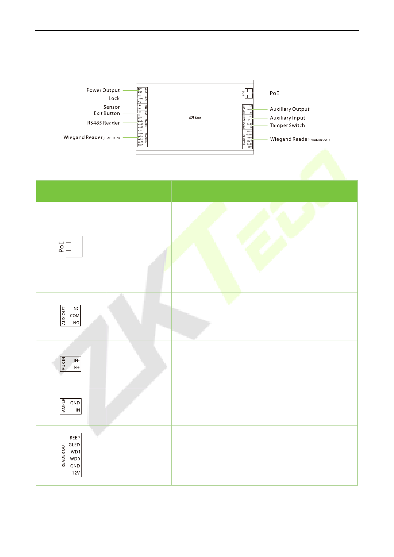
4 DE10
Terminal Description
PoE
Interfaces with the InBioPC series intelligent identification
access controller.
Compliant with IEEE 802.3at standard, DE10
recommended
total output curre
nt less than 1.5A to external loads,
including VOUT output, 485 reader
power output,
Wiegand reader
power output, electric lock output,
auxiliary output and so on.
Auxiliary Output
Connect to alarm or doorbell, etc.
Maximu
m switching voltage of the contact is 24VDC,
maximum switching current is 1A.
Auxiliary Input
Connect infrared human body sensor detector or smoke
detector, etc.
Maximum input voltage 12VDC
Tamper Switch
Timely notification to stop illegal dismantling of device.
Maximum input voltage 12VDC.
Wiegand Reader
(Reader Out)
Maximum output voltage 12VDC, maximum output
current 0.5A, maximum input voltage 12VDC
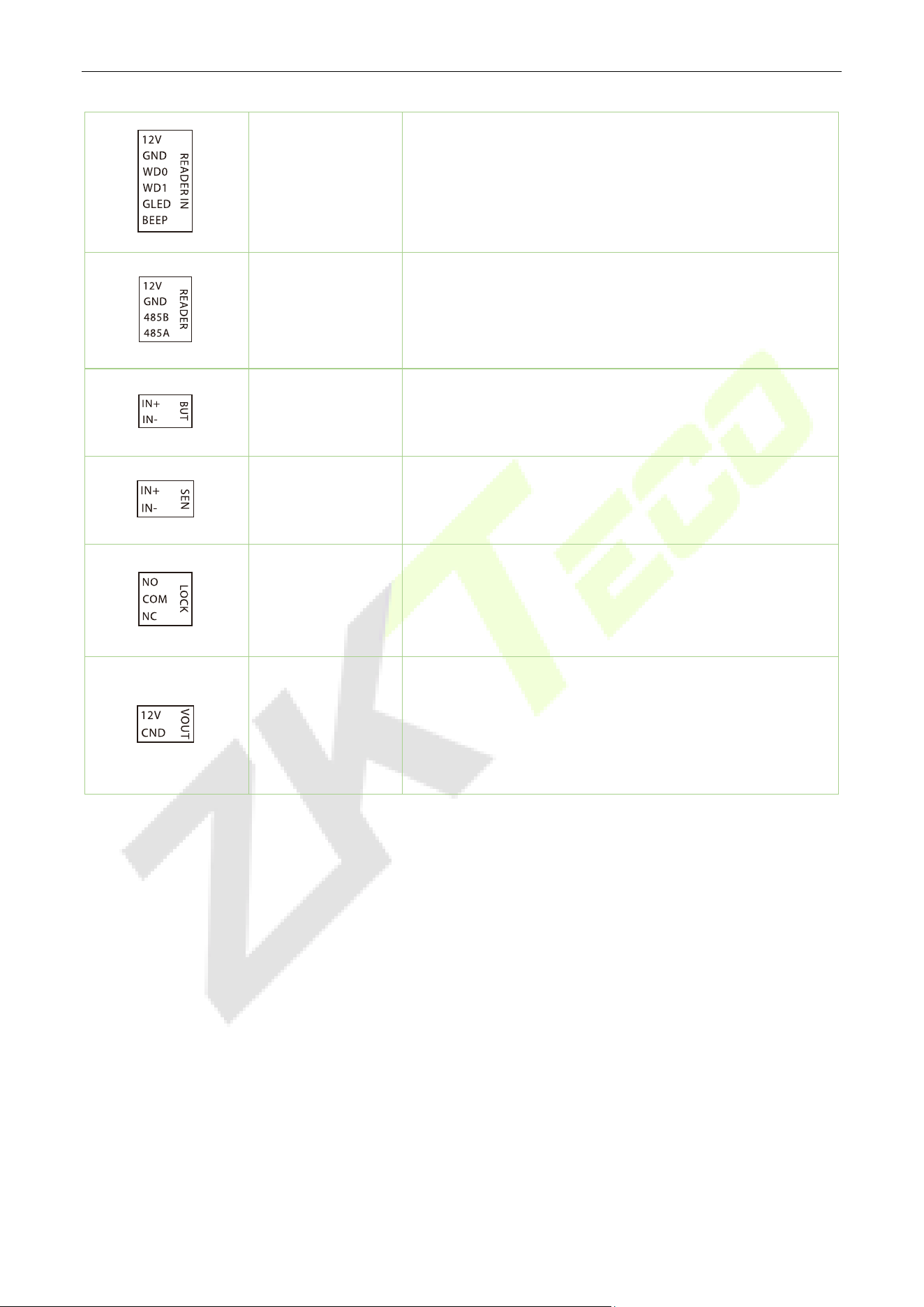
InBioPC Series User Manual
Page | 20 Copyright©2025 ZKTECO CO., LTD. All rights reserved.
Wiegand Reader
(Reader In)
Maximum output voltage 12VDC, maximum output
current 0.5A, maximum input voltage 12VDC
RS485 Reader
Maximum output voltage 12VDC, maximum output
current 0.5A, maximum input voltage 6VDC
Exit Button
Connection of door exit button
Maximum input voltage 12VDC
Sensor
Connecting door sensor
Maximum input voltage 12VDC
Lock
Connecting door lock
Maximum switching voltage of contacts 30VDC, maximum
switching current 5A
Power Output
12V power output from DE10 (connected to InBioPC series
directly via PoE)
Maximum output voltage 12VDC, maximum output
current 1A

InBioPC Series User Manual
Page | 21 Copyright©2025 ZKTECO CO., LTD. All rights reserved.
4.1 Wire Selection Instructions
Name Specifications Maximum Distance
Wiegand
Adopt 6-core communication shielded cable (RVVP
6*0.5mm²) (usually 6-core, 8-core, 10-core, users can
choose according to the need of the port), to reduce
the interference during transmission
20m
Electric lock
4-core cable (RVV 4* 0.75mm², 2-core power, 2-core
door magnet) is used to minimize the impact on
other components during the operation of the
electric lock
20m
Exit Button Use of 2- or 4-core cable (RVV 2 * 0.5mm²) 20m
RS485 Reader
4-core communication cable (RVVSP 2 * 2 * 0.5mm²)
is used
20m with controller power
supply
Network Cable
Network cable selection must be Super Category 5
network cable oxygen-
free copper material above
specifications, core n
ominal diameter 0.5mm. 100
meters of single wire resistance is less than 10 ohms.
Try to choose a higher specification network cable
(such as Category 6 oxygen-
free copper material),
reserve enough margin to meet the maximum load
requirements
100m
InBioPC Series User Manual
Page | 22 Copyright©2025 ZKTECO CO., LTD. All rights reserved.
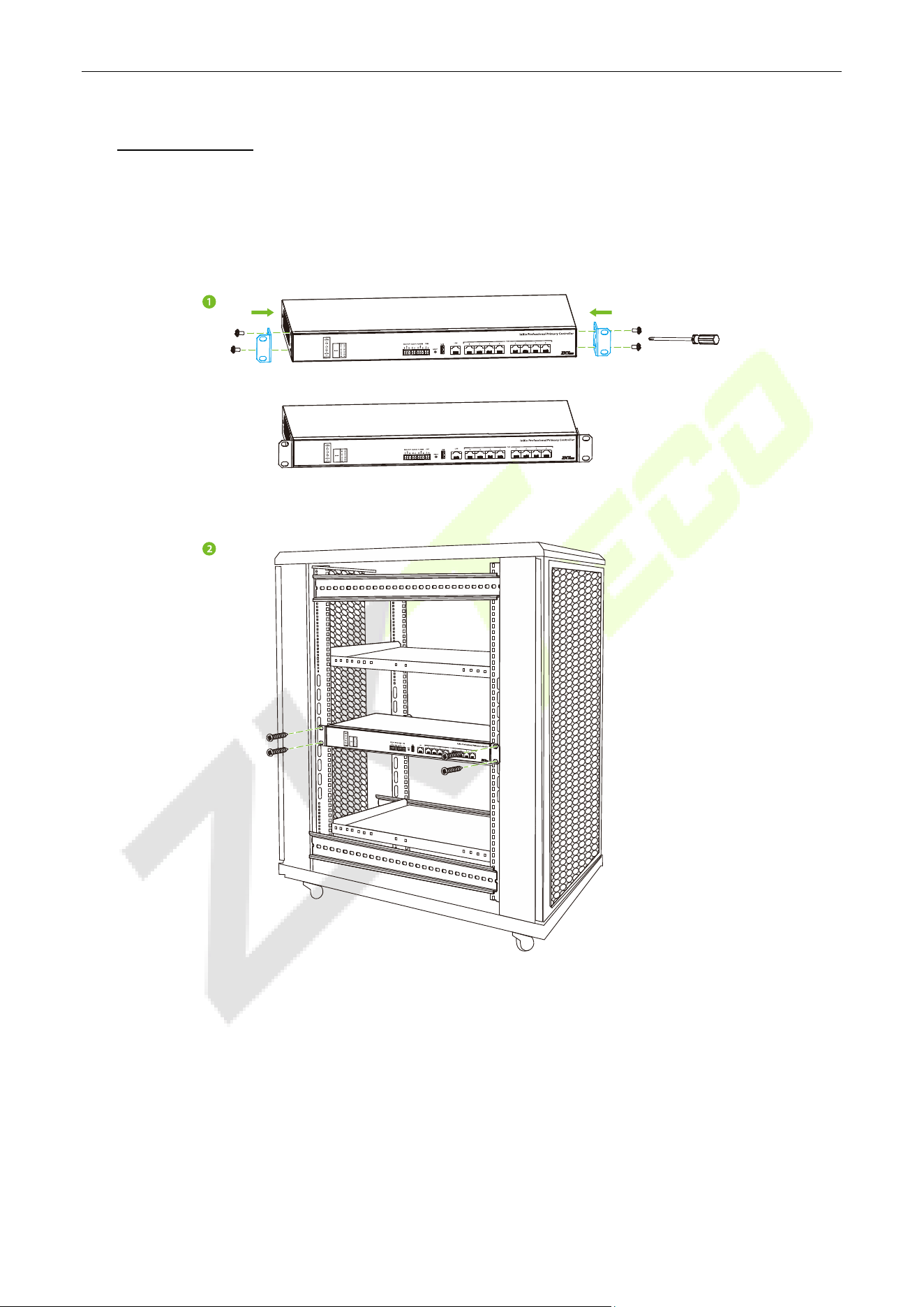
5 Installation
Installation in Cabinet
1. Attach the Back Plate to the device as shown in the figure below.
2. Place the device in the cabinet and secure it with screws.
InBioPC Series User Manual
Page | 23 Copyright©2025 ZKTECO CO., LTD. All rights reserved.
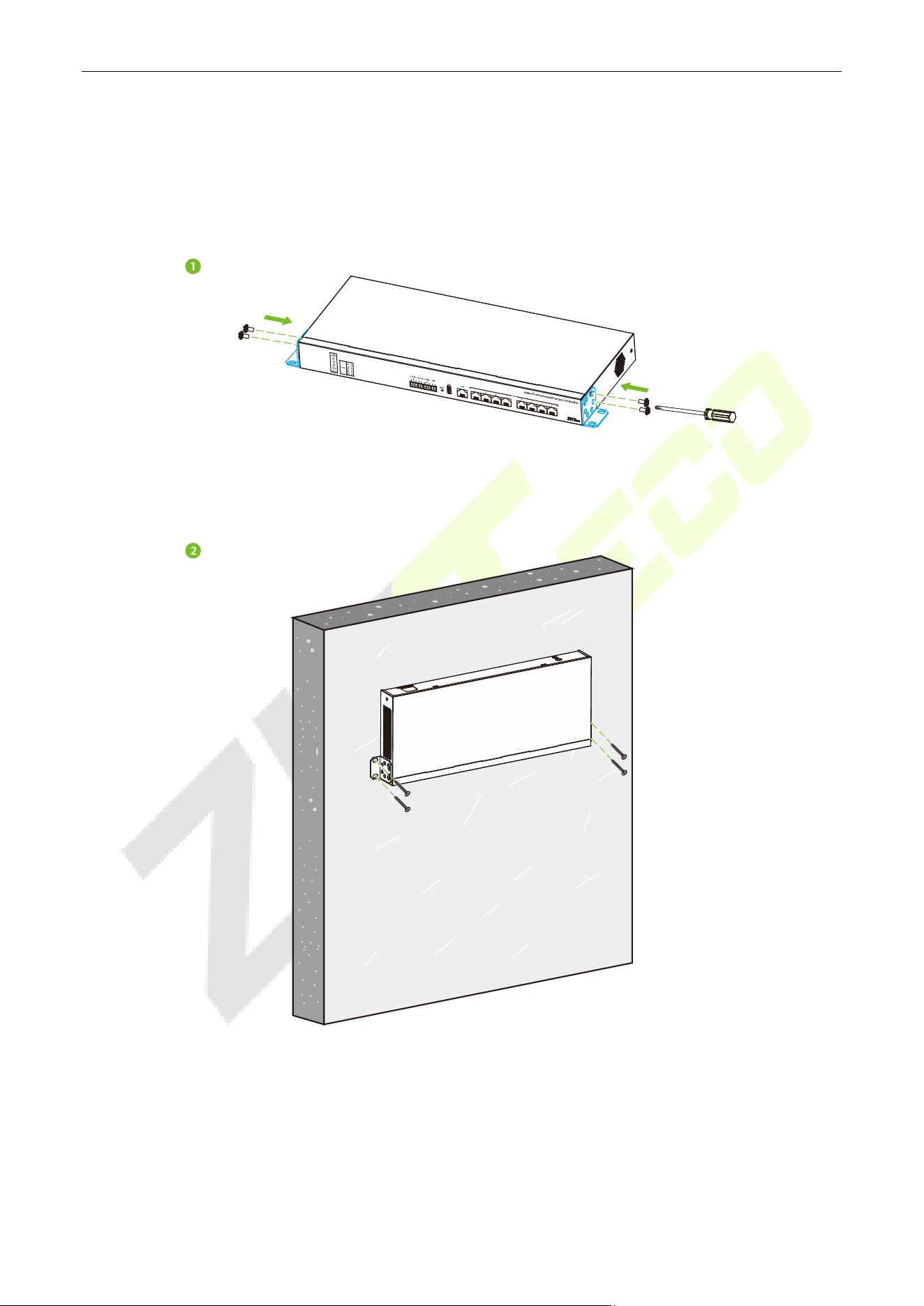
Wall Mount
1. Attach the Back Plate to the appliance as shown in the figure below.
2. Secure the device to the wall with screws.
InBioPC Series User Manual
Page | 24 Copyright©2025 ZKTECO CO., LTD. All rights reserved.
6 Access Controller Wiring
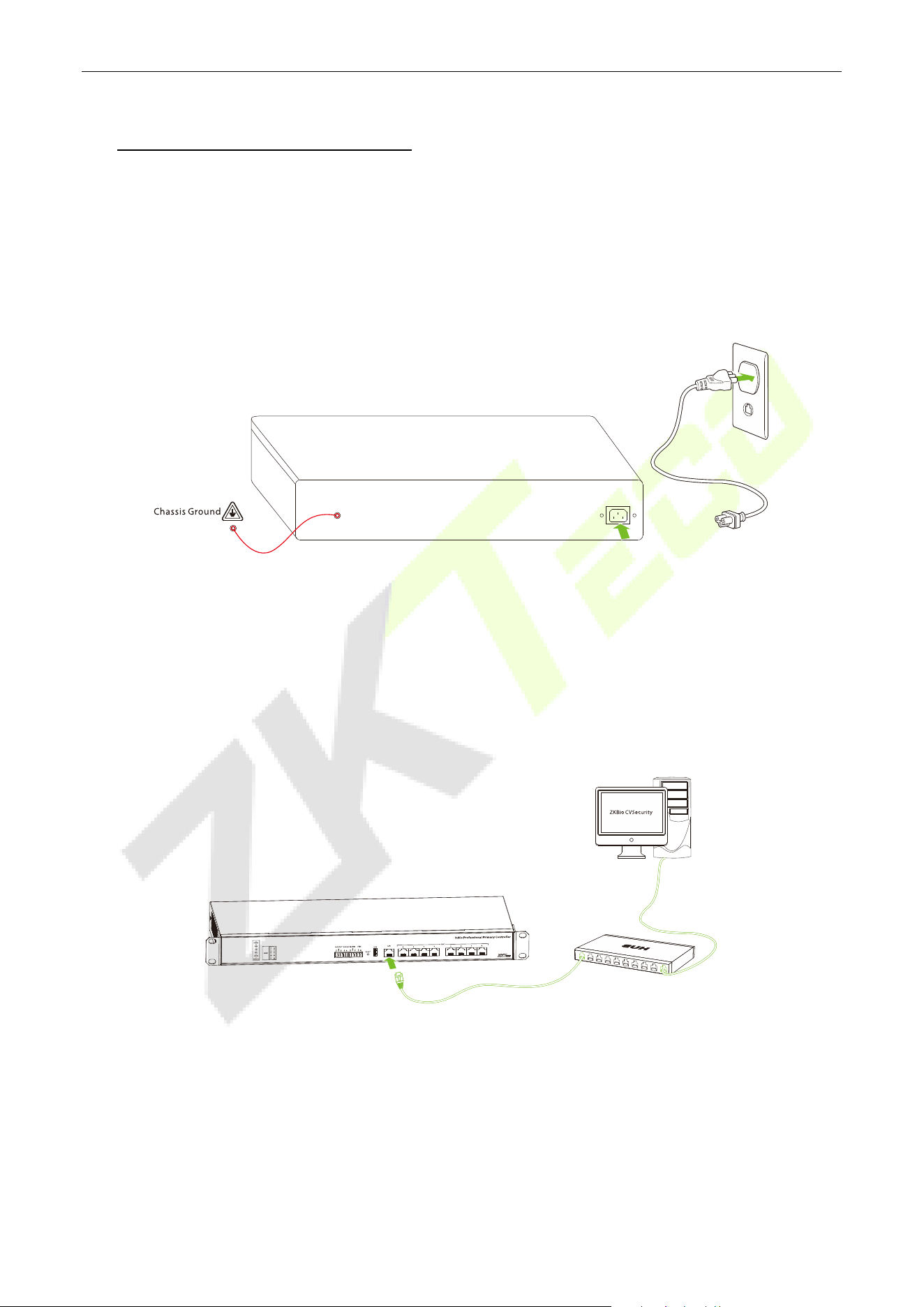
6.1 Power Supply Connection
Please use the power supply configured for the InBioPC series controller which is rated 100 - 240V, AC
50/60Hz.
Note: Before connecting the power supply, please make sure that the controller is well connected to the
chassis ground and the AC ground is truly grounded.
6.2 Computer Connection
Connect the InBioPC series controller to the PC software via an Ethernet cable. The wiring is shown below:
Note: The default IP address of the primary NIC is 192.168.1.201.
InBioPC Series User Manual
Page | 25 Copyright©2025 ZKTECO CO., LTD. All rights reserved.
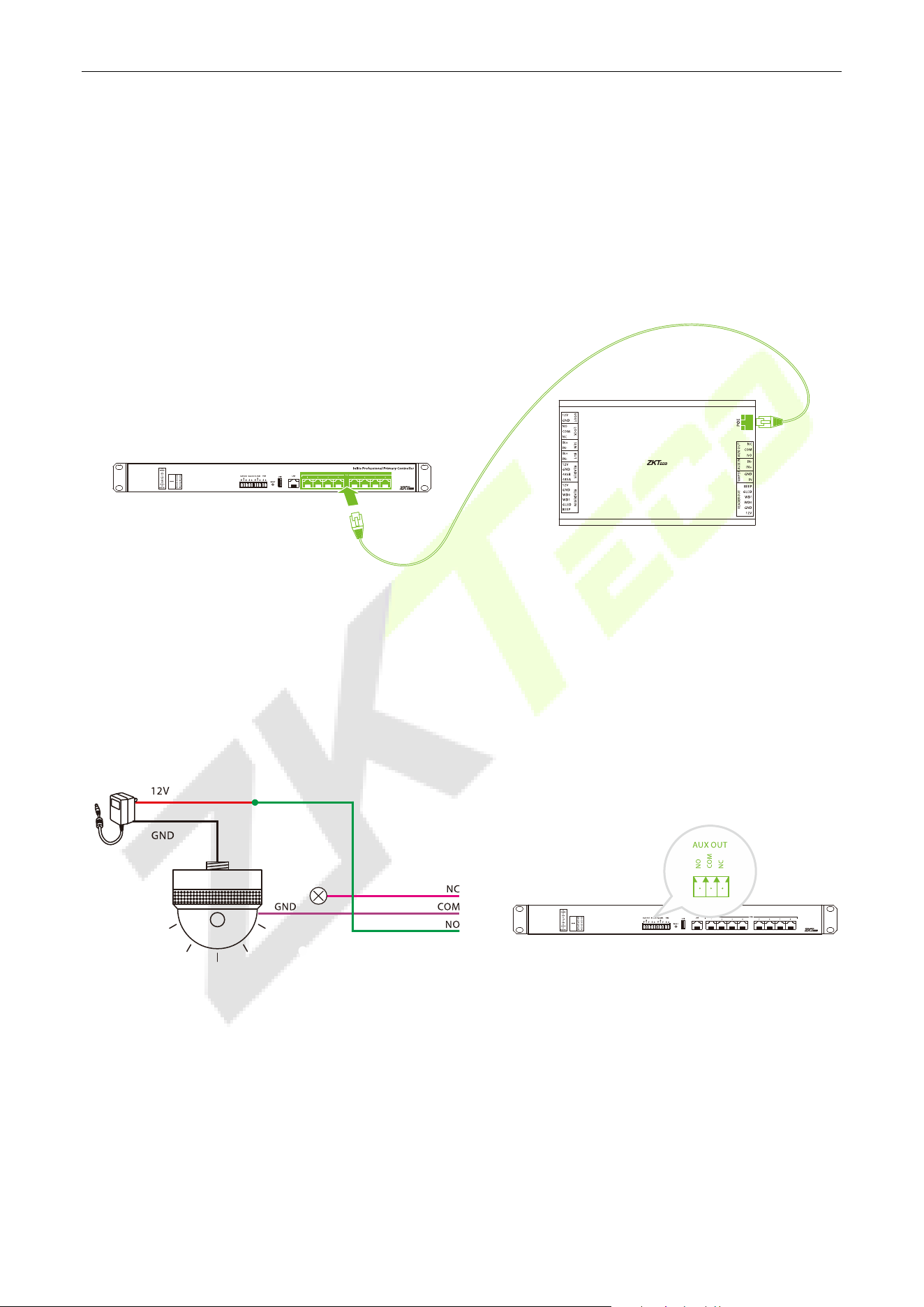
6.3 DE10 Connection
The InBio PC series controller communicates with the DE10 door units via a single network cable that also
provides Power over Ethernet (PoE IEEE 802.3at). The DE10 units then connect to readers, exit buttons,
locks, and other peripheral devices, creating a streamlined architecture. This design significantly reduces
installation complexity, minimizes connection errors, lowers installation costs, and simplifies maintenance
by eliminating troublesome traditional wiring methods.
6.4 Auxiliary Outputs Connection
The InBioPC series provides 1 auxiliary output connector for connecting an audible and visual alarm. Upon
receiving signals such as fire alarms or unauthorized intrusions, the alarm will emit audible alerts and
visual signals.
InBio Professional Primary Controller
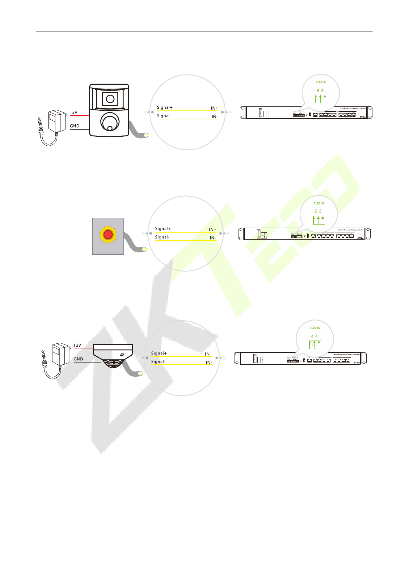
6.5 Auxiliary Inputs Connection
The InBioPC series provides 1 auxiliary input port for connecting infrared body sensing detectors, fire
alarms or smoke detectors etc.
InBioPC Series User Manual
Page | 26 Copyright©2025 ZKTECO CO., LTD. All rights reserved.
Infrared Human Body Sensor Detector
Fire
Smoke Detector
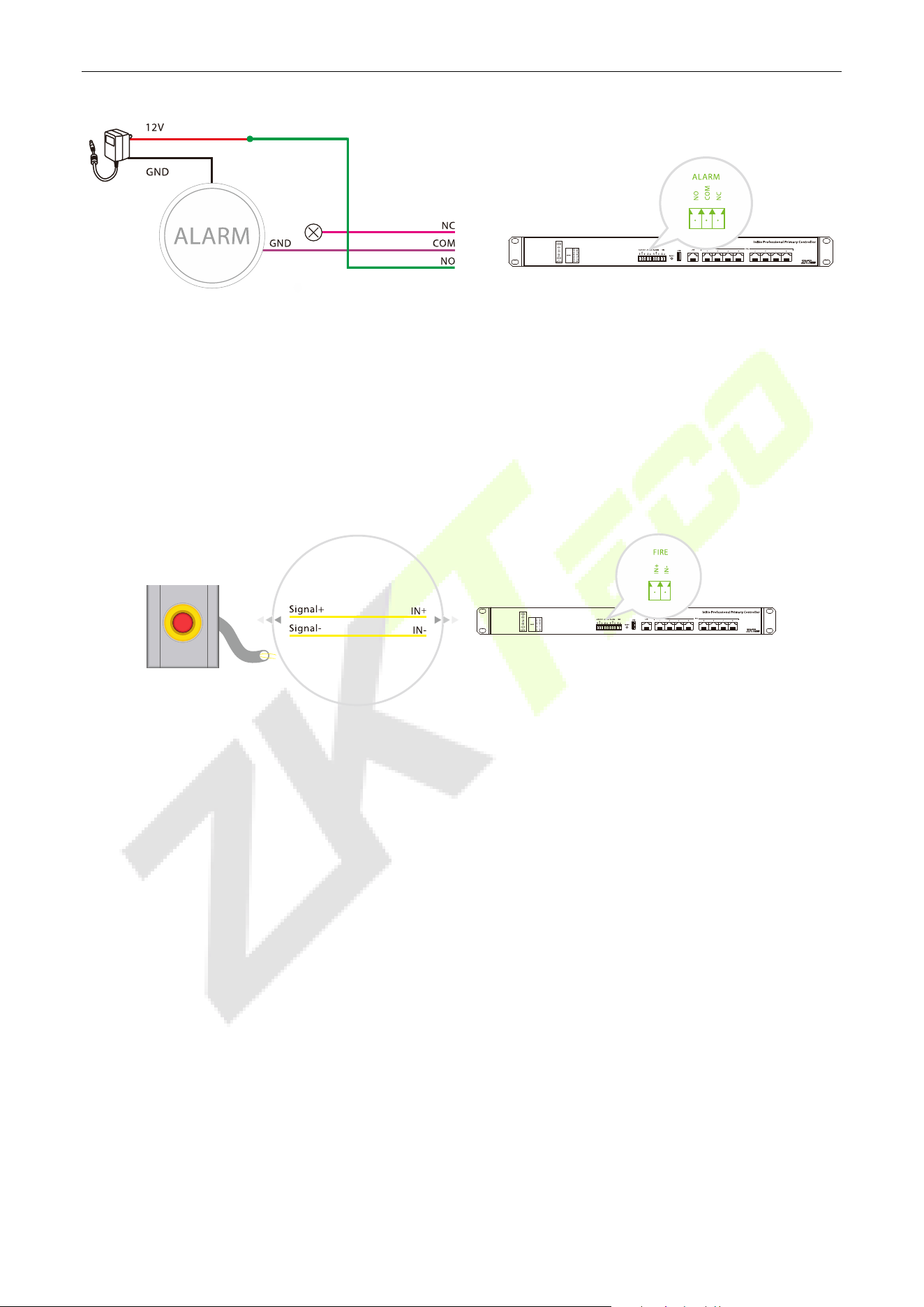
6.6 Alarm Connection
The alarm sounds when signals such as fire alarms or break-ins are received.
InBioPC Series User Manual
Page | 27 Copyright©2025 ZKTECO CO., LTD. All rights reserved.
6.7 Fire Protection Input Interface Connection
When the fire protection input interface is short-circuited, all doors of the unit automatically enter the
normally open state, the alarm, and the global linkage function (need to be turned on). When the
equipment restarts, it does not affect the normal function of the fire fighting interface.
InBioPC Series User Manual
Page | 28 Copyright©2025 ZKTECO CO., LTD. All rights reserved.
7 DE10 Wiring
7.1 Reader Connection
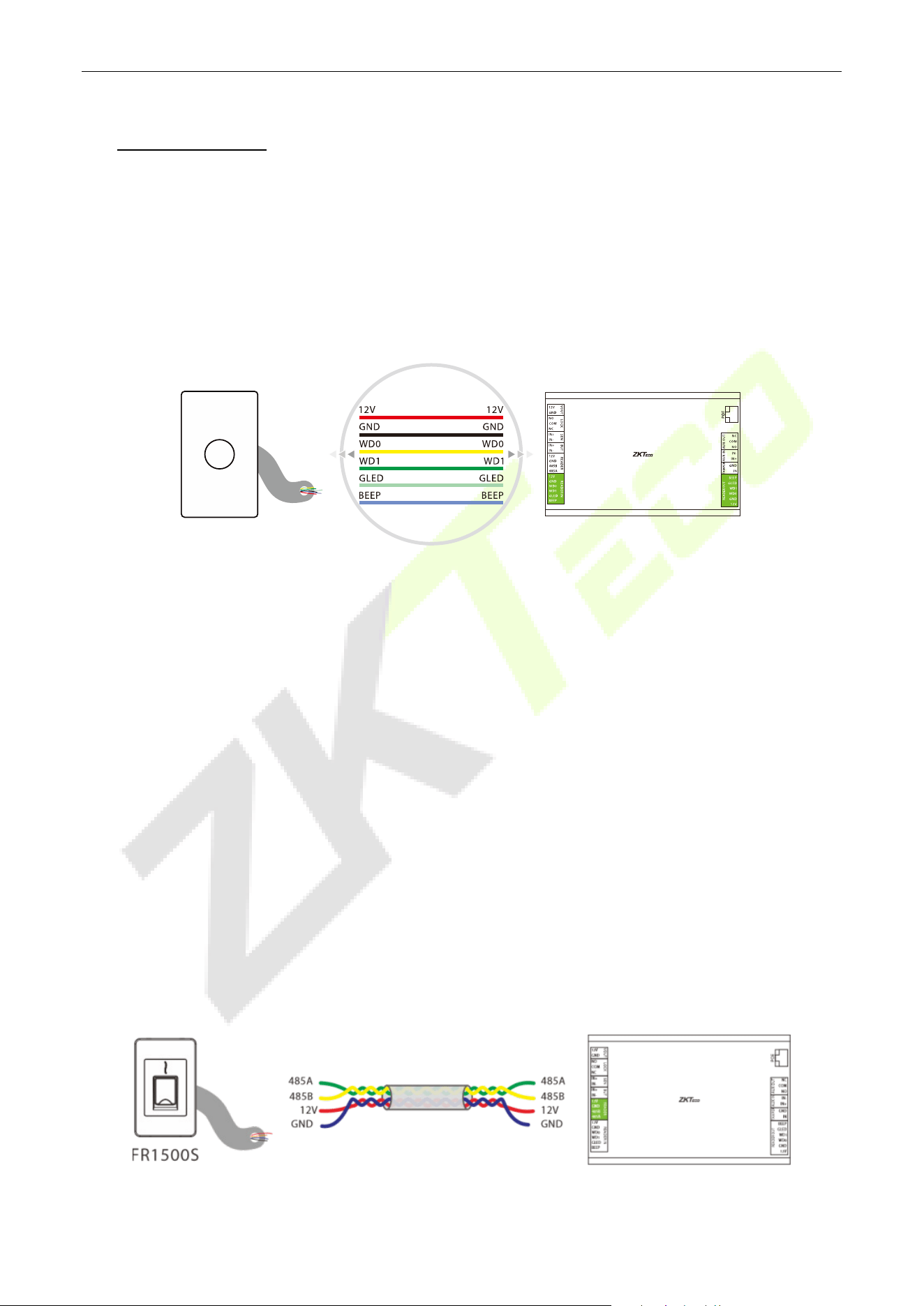
7.1.1 Wiegand Reader Connection
Taking the ProID103 reader as an example, after the InBioPC series is successfully connected to the DE10,
connect the Wiegand interface between the DE10 and the ProID103.
Note:
1. One DE10 has two Wiegand reader interfaces, up to 2 Wiegand readers can be connected, and single
door bidirectional can be set up.
2. The reader should be installed about 1.4m from the ground and 30 ~ 50mm from the door edge.
7.1.2 Connecting the RS485 Reader
1. Shielded twisted-pair cables, which are internationally recognized, must be used. The recommended
type of shielded twisted-pair cable is RVVSP4*0.5. The use of shielded twisted-pair cable helps to
reduce and eliminate the distributed capacitance between the two 485 communication lines as well
as the common-mode interference generated around the communication lines.
2. 485A and 485B data lines must be twisted, DE10 GND, 485A, 485B were connected to the RS485
reader GND, 485A, 485B. wiring must be cloth multi-stranded shielded twisted-pair cable, multi-
stranded for backup, shielding is for debugging when a special situation arises, twisted because of the
485 communication using the principle of differential mode communication, twisted anti-jamming of
the best.
InBioPC Series User Manual
Page | 29 Copyright©2025 ZKTECO CO., LTD. All rights reserved.
Note:
1. A DE10 has one RS485 reader interface and up to 2 RS485 readers can be connected, the RS485
address codes must be 1 and 2.
2. The reader should be installed about 1.4m from the ground and 30 ~ 50mm from the door edge
frame.
3. When DE10 is not connected to the controller's PoE port which is set as Master-slave mode or DE10 is
in factory default state without prior controller connection, validating any card, password, fingerprint,
or QR code on externally connected readers will successfully unlock the door lock for 5 seconds, no
access records will be saved. (The controller ‘s PoE port mode can be set on the Webserver)
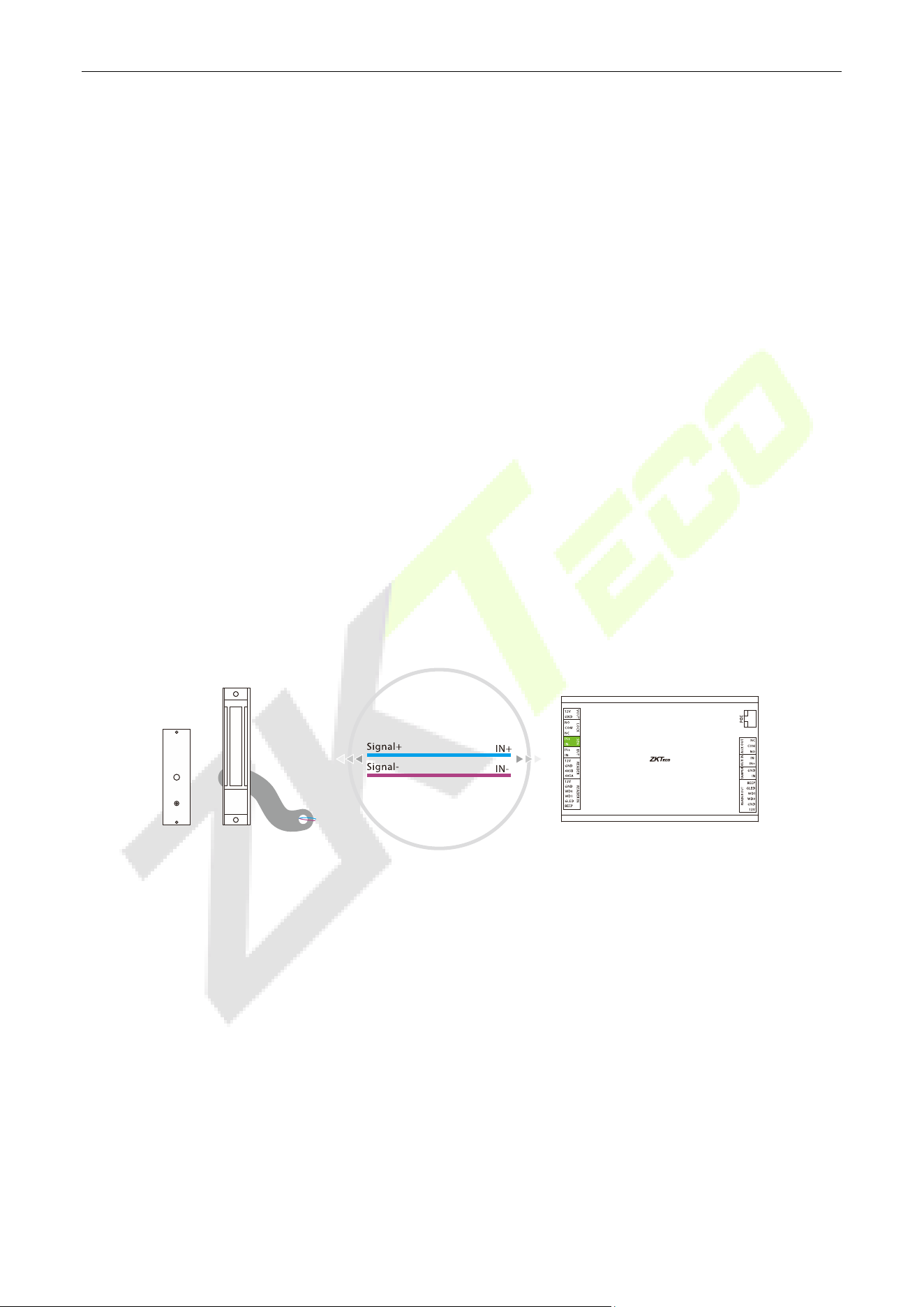
7.2 Connecting the Sensor
Door sensor is used to sense the switching state of the door, the access controller can detect the door
being opened illegally through the door sensor switch, and then the alarm will be output. In addition, after
opening the door in more than a specified period of time did not close the door, the access controller will
also prompt the alarm. It is recommended to choose two-core wire, wire diameter of 0.22 square
millimeters or more. If there is no need to know the switching status of the door online and no need for
the door to be left open for a long time alarm, break-in alarm and interlock and other functions, the door
sensor may not be connected.
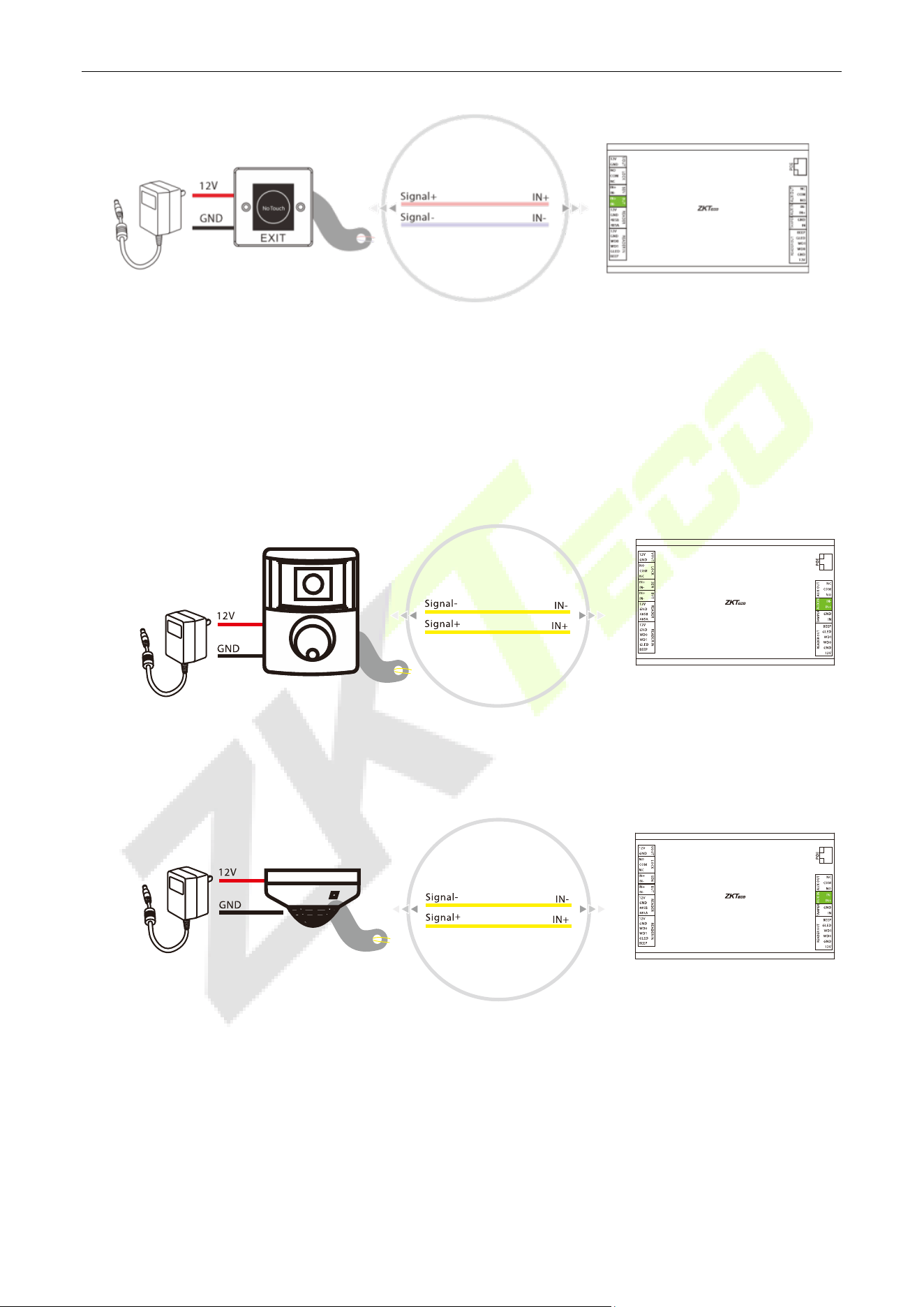
7.3 Connecting the Exit Button
The exit button is a switching device for opening the door installed inside the room, and the door can be
opened when the exit button is closed. The exit button is fixed at about 1.4 meters from the ground, and it
should be ensured that the position of the exit button is correct, without distortion, and the wiring is
accurate and firm (pinch off the exposed end of the unused wires and wrap them with insulating tape). Be
careful to prevent electro sensor interference (such as: lighting switches, computers, etc.). It is
recommended to use two-core wires with a cross-section area of 0.3 mm
2
or more for the wires connecting
the exit button to the controller.
InBioPC Series User Manual
Page | 30 Copyright©2025 ZKTECO CO., LTD. All rights reserved.
7.4 Auxiliary Input Connection
The DE10 provides 1 auxiliary input port for connecting infrared body sensing detectors or smoke
detectors etc.
Infrared Human Body Sensor Detector
Smoke Detector
InBioPC Series User Manual
Page | 31 Copyright©2025 ZKTECO CO., LTD. All rights reserved.
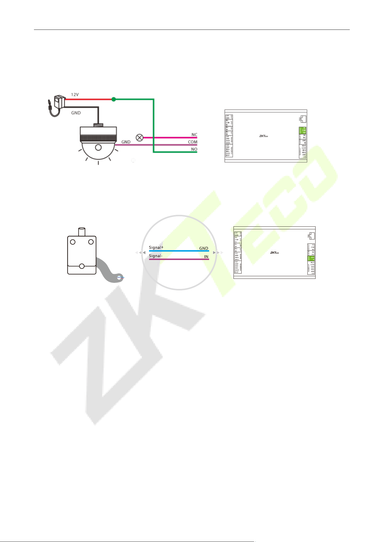
7.5 Auxiliary Output Connection
The DE10 provides 1 auxiliary output connector for connecting an audible and visual alarm.
7.6 Tamper Switch Connection
The tamper signal of the DE10 is connected to the tamper switch of the cabinet.
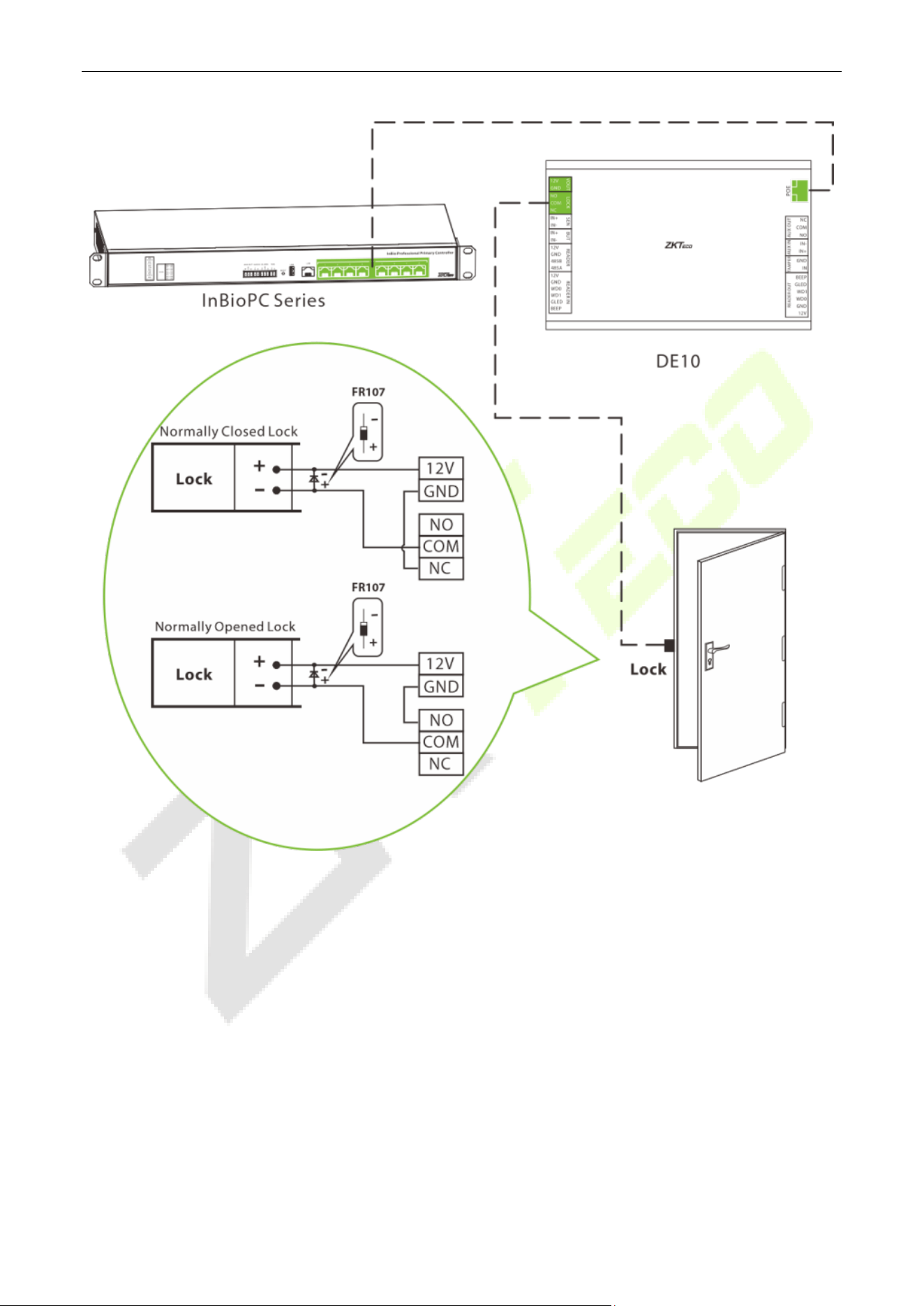
7.7 Lock Connection
1. One DE10 supports the control of a number of door locks.
2. The system supports both Normally Opened Lock and Normally Closed Lock. The NO Lock (normally
opened when powered) is connected with 'NO1' and 'COM' terminals, and the NC Lock (normally
closed when powered) is connected with 'NC1' and 'COM' terminals.
3. In order to prevent the electric lock from generating self-induced electromotive force on the access
control system at the moment of switching, it is necessary to connect a diode in parallel with the
electric lock (please use the FR107 supplied with the system) to release the self-induced electromotive
force during the wiring of the field application of the access control system.
4. The VOUT terminal of the DE10 can supply power to the electric lock, but the lock's current draw must
be less than 800mA.
InBioPC Series User Manual
Page | 32 Copyright©2025 ZKTECO CO., LTD. All rights reserved.
InBioPC Series User Manual
Page | 33 Copyright©2025 ZKTECO CO., LTD. All rights reserved.
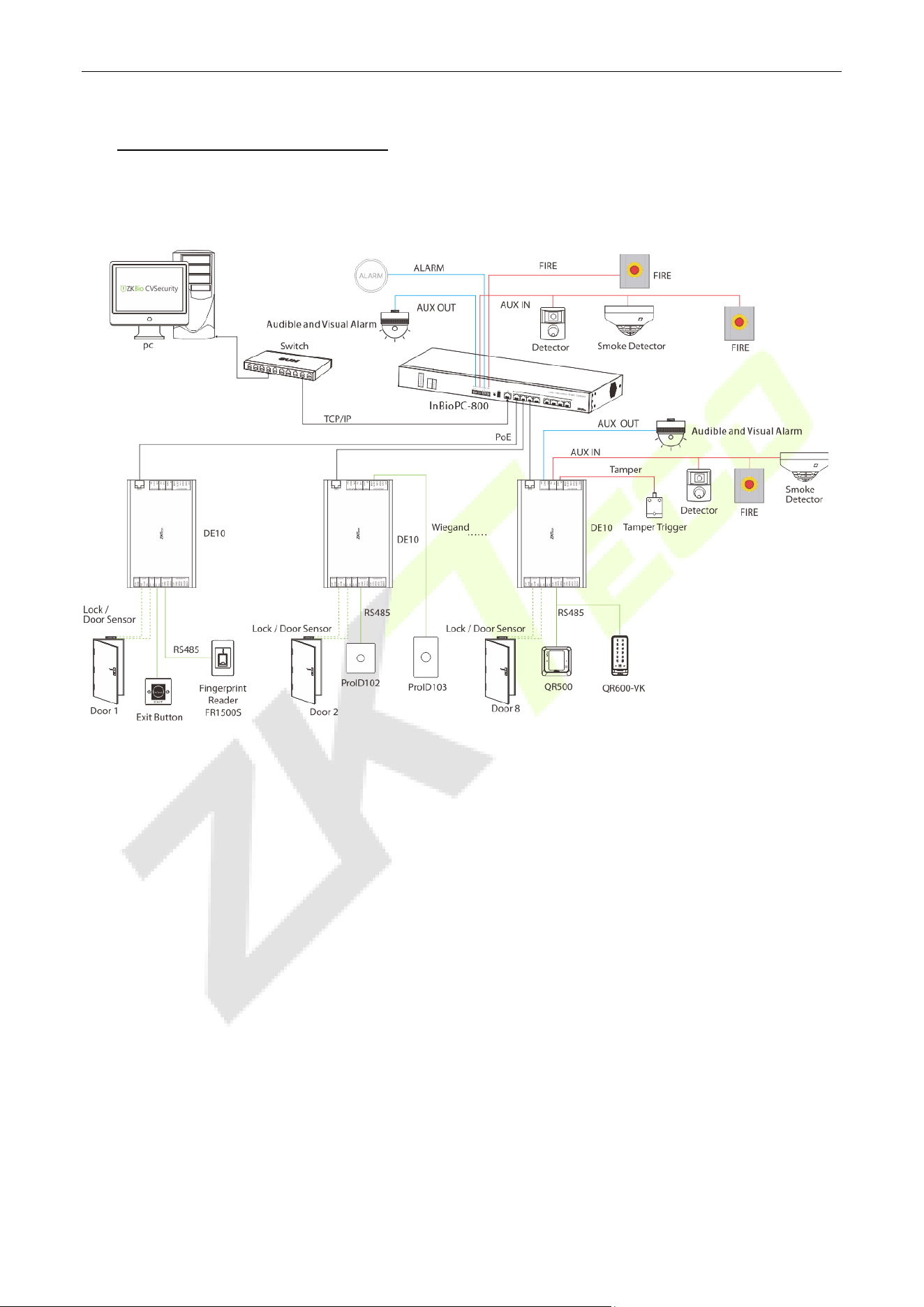
8 Access Control System
Please use the power supply configured for the InBioPC series controller which is rated 100 - 240V, AC
50/60Hz.
InBioPC Series User Manual
Page | 34 Copyright©2025 ZKTECO CO., LTD. All rights reserved.
9 Login to WebServer
The device has a built-in WebServer, which supports setting device parameters and checking device status,
etc. on PC and cell phone.
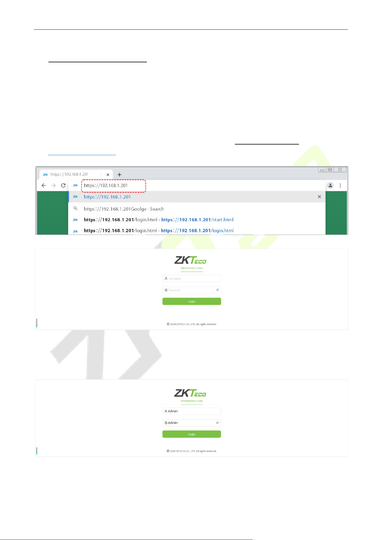
9.1 PC
1. After the device is connected to power and connected to the network, open a browser and log in to
the WebServer by entering the address, which is the https:// IP address. For example:
https://192.168.1.201.
2. Enter the WebServer account and password, the default account is: admin and the password is:
admin.
InBioPC Series User Manual
Page | 35 Copyright©2025 ZKTECO CO., LTD. All rights reserved.
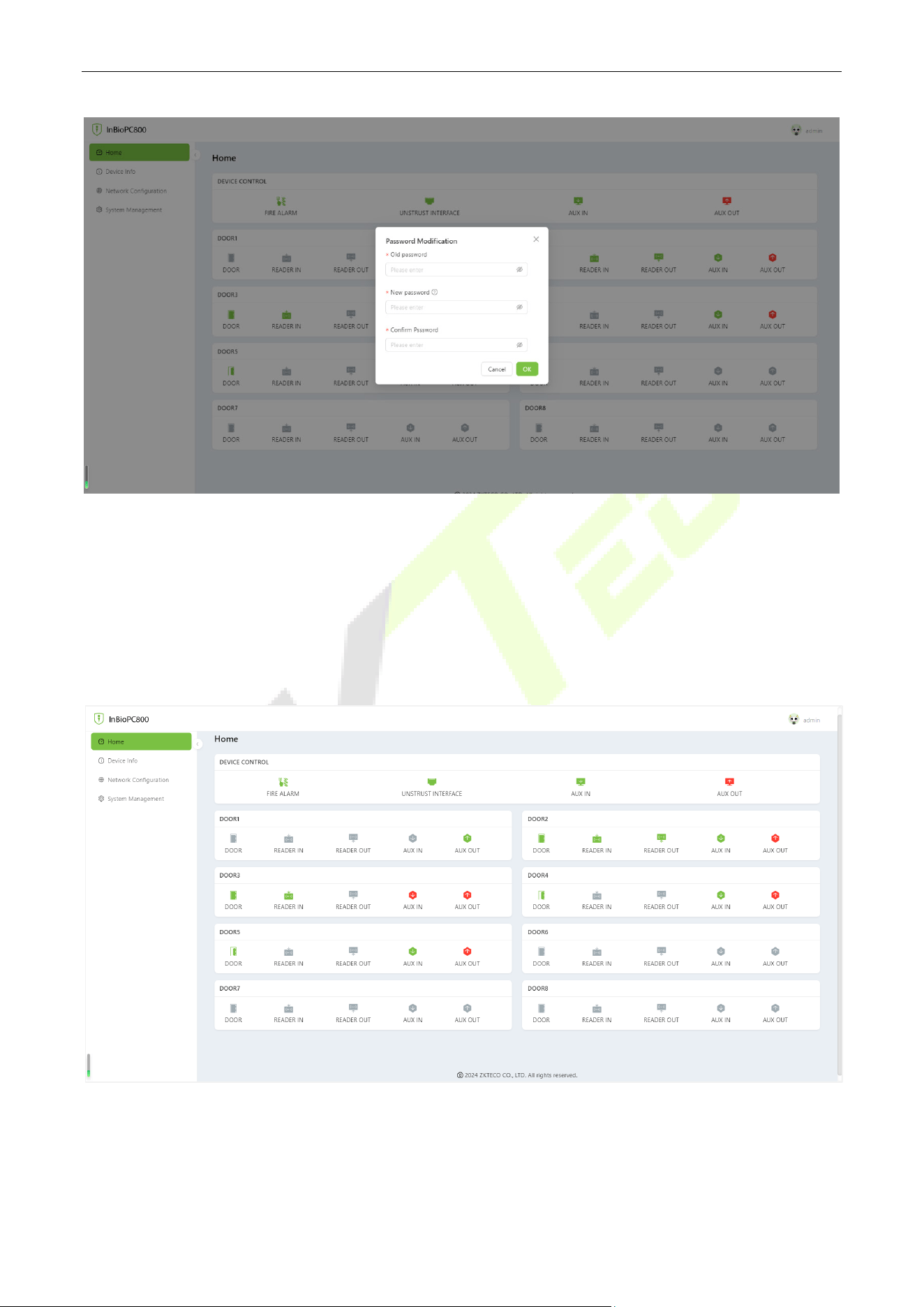
Note: The system is the initial password, the user logs in or visits the home page, the system reminds to
modify the password, modify the success of the need to re-login.
Status Information
In the opened WebServer page, click [Home] to view the status information of all peripheral devices
connected to the device such as reader, auxiliary input, auxiliary output, network and door.
InBioPC Series User Manual
Page | 36 Copyright©2025 ZKTECO CO., LTD. All rights reserved.
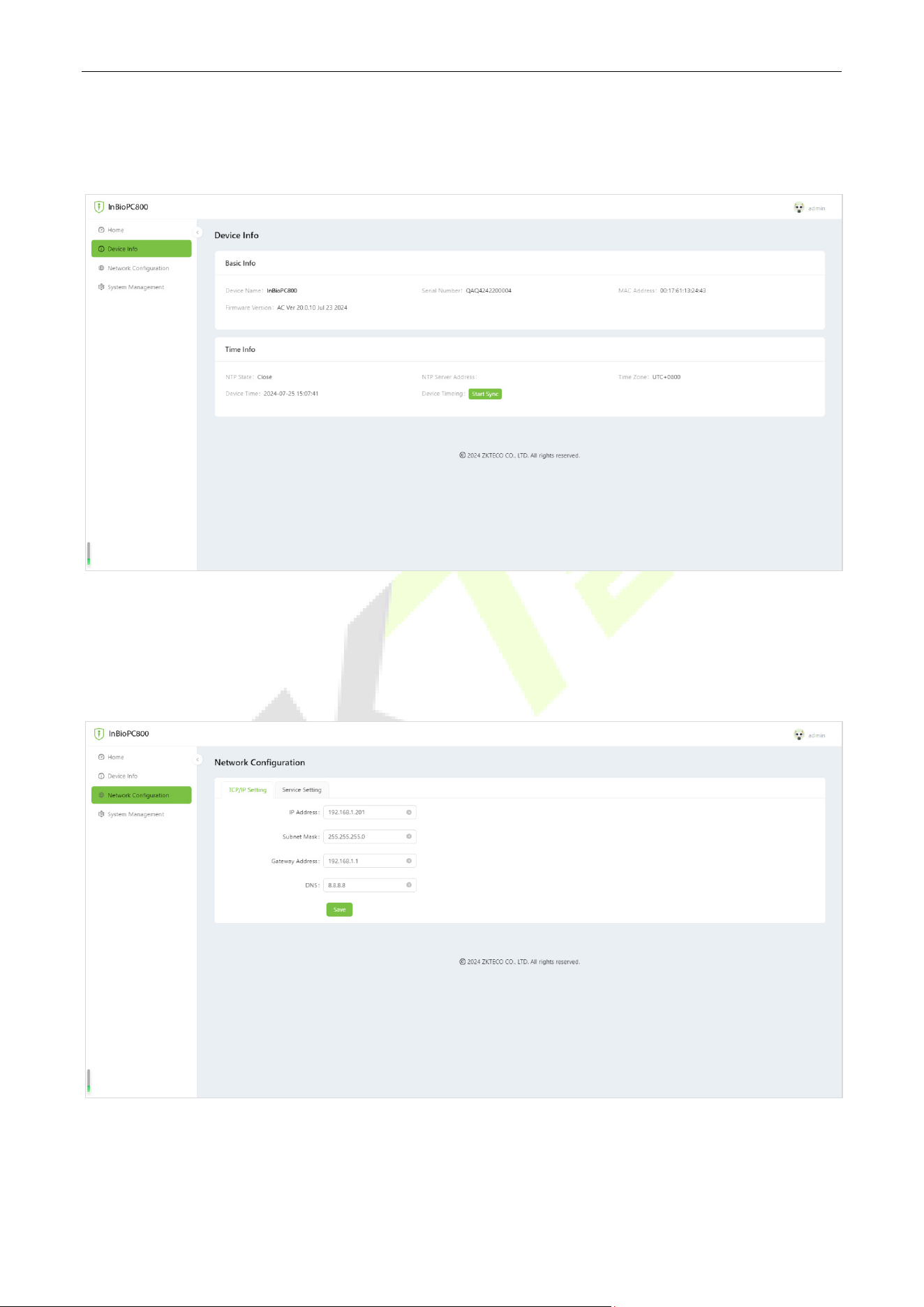
Device Information
Click [Device Info] to browse the basic information and time information of the device.
Network Configuration
Click [Network Configuration] > [TCP/IP Setting] to change the IP address of the device, and you need
to log in again after changing the IP address.
InBioPC Series User Manual
Page | 37 Copyright©2025 ZKTECO CO., LTD. All rights reserved.
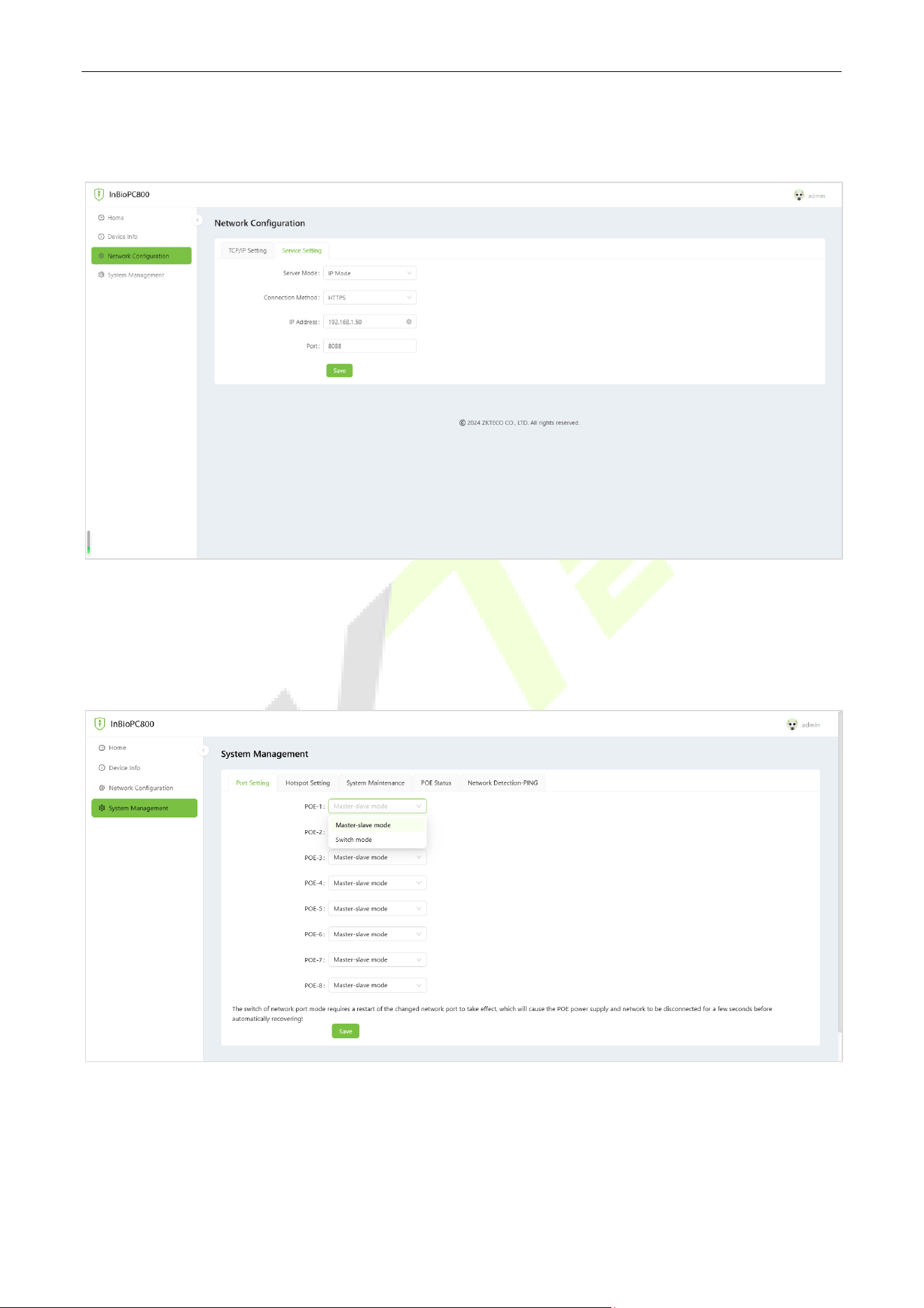
Click [Network Configuration] > [Service Setting] to support devices to connect to the server, such as
ZKBioCVSecurity.
System Management
Click [System Management] to support setting device PoE port mode, setting Wi-Fi hotspot and
reboot/restore factory settings/device upgrade.
Note: The PoE port can be set as Main-sub mode or Switch mode. The switch of network port mode
requires a restart of the changed network port to take effect which will cause the PoE power supply and
network to be disconnected for a few seconds before automatically recovering!
InBioPC Series User Manual
Page | 38 Copyright©2025 ZKTECO CO., LTD. All rights reserved.
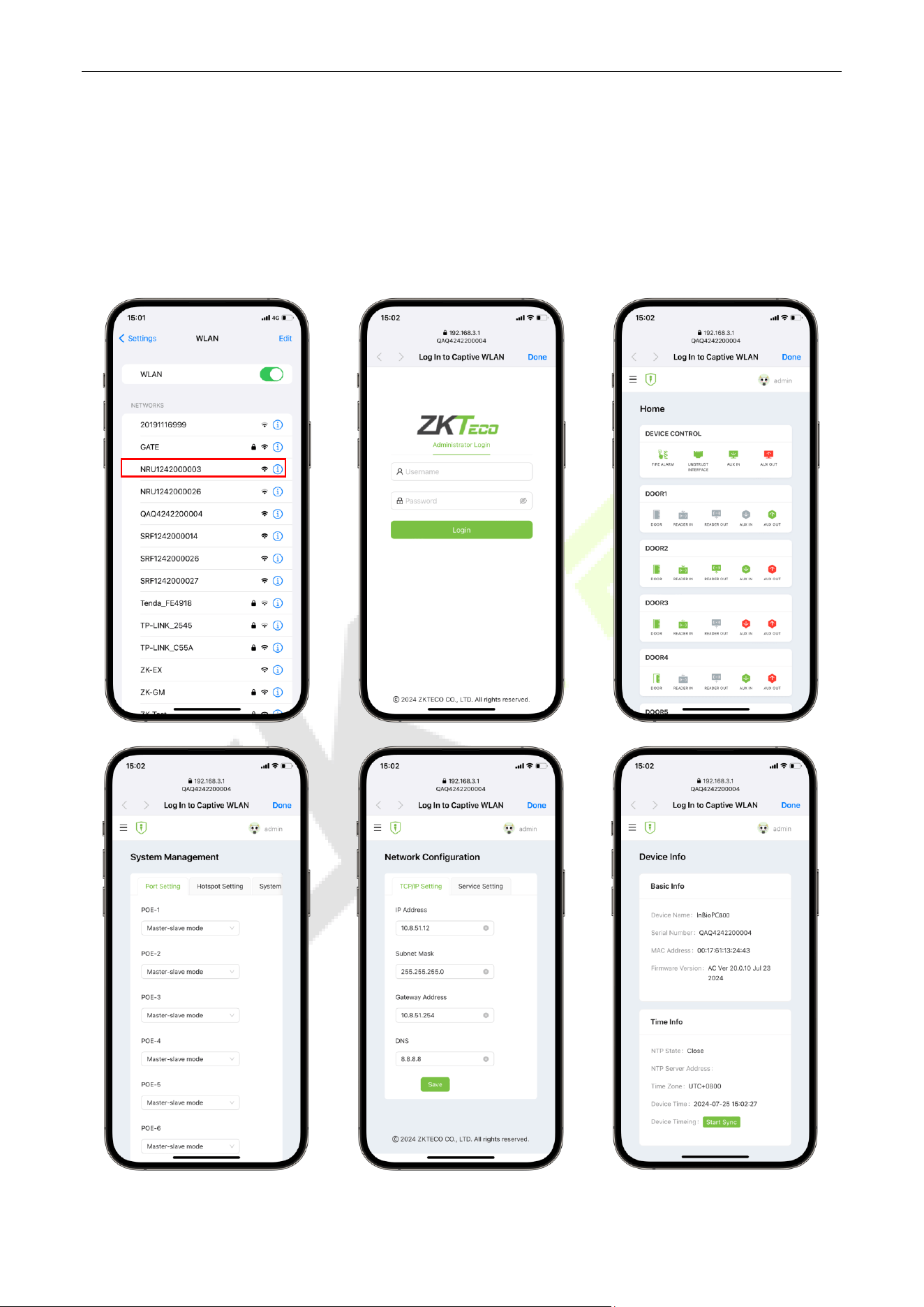
9.2 Phone
There is no need to enter the IP address of the device on the cell phone. After the device is connected to
the power supply and the network, the cell phone should be close to the device, find the hotspot of the
device (by default, it is the serial number of the device), and then click on it and enter the WebServer
account and password in the pop-up login interface.
InBioPC Series User Manual
Page | 39 Copyright©2025 ZKTECO CO., LTD. All rights reserved.
10 ZKBio CVSecurity Integration
The device connects to ZKBio CVSecurity by setting up ZKBio CVSecurity-related information in [Web
Configuration] > [Server Settings] of the WebServer (no need to set up if the device and the server are in
the same network segment). The device can add devices, set up access control rules, set up global anti-
passback, linkage, interlocking, and other access control operations on ZKBio CVSecurity.
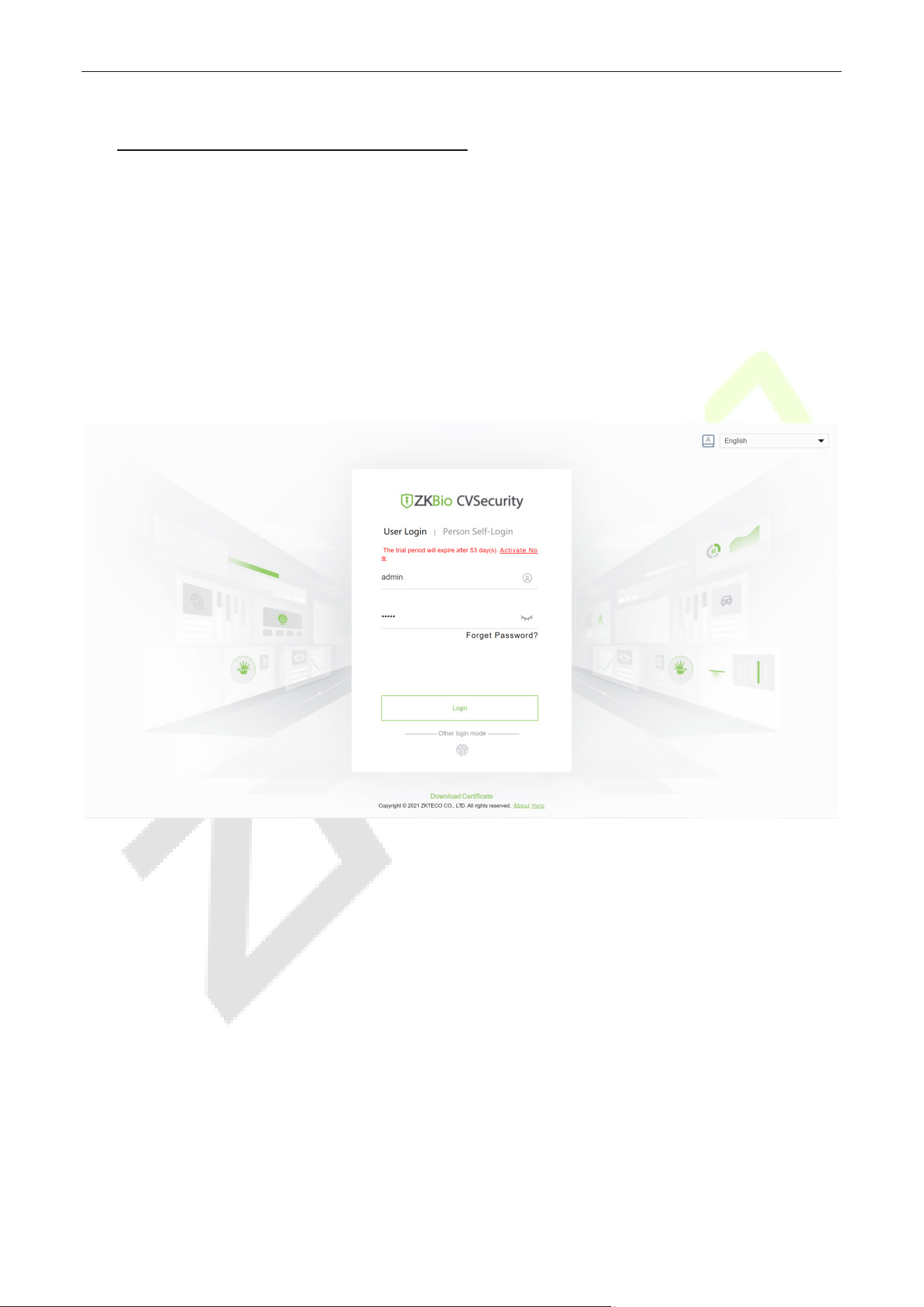
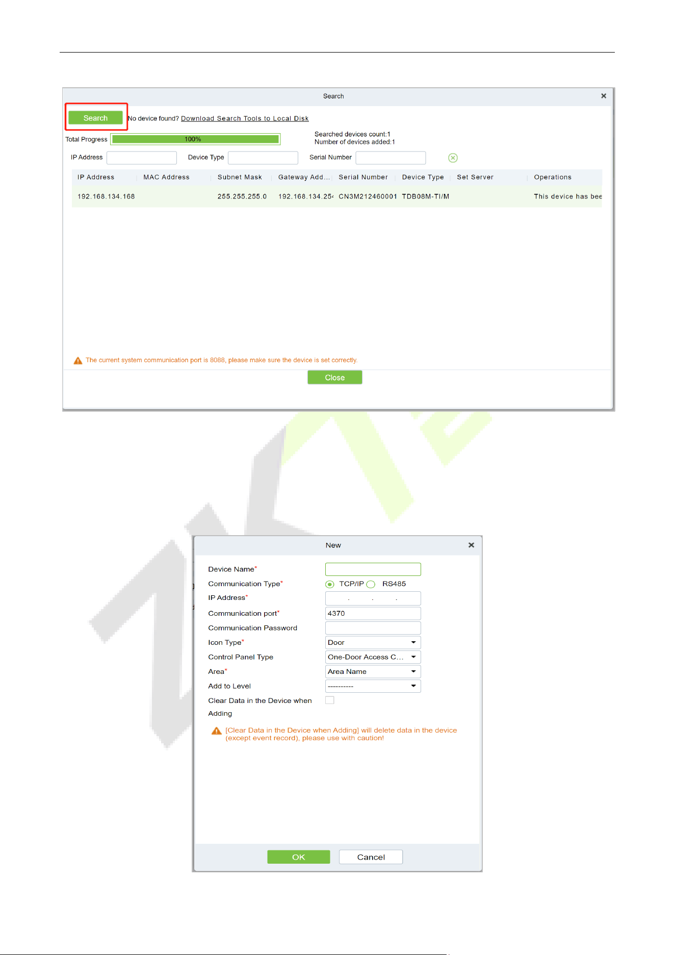
10.1 Add the Device
1. Open ZKBio CVSecurity and log in to ZKBio CVSecurity by entering your account number and
password.
2. In the Access Control module, select [Device] > [Access Control Device].
3. On the device interface, click the [Search] button to pop up a search box.
4. Click [Start Search] in the search box to display the access control devices that can be added, as
shown in the figure below.
InBioPC Series User Manual
Page | 40 Copyright©2025 ZKTECO CO., LTD. All rights reserved.
5. Optional: Modify the IP address of the Access Control device, click [Modify IP Address], the device
will be restarted after modifying the IP address, and the IP address modification will be completed
after the restart.
6. For the searched access control devices, click the [Add] button in the operation bar to add the device.
InBioPC Series User Manual
Page | 41 Copyright©2025 ZKTECO CO., LTD. All rights reserved.
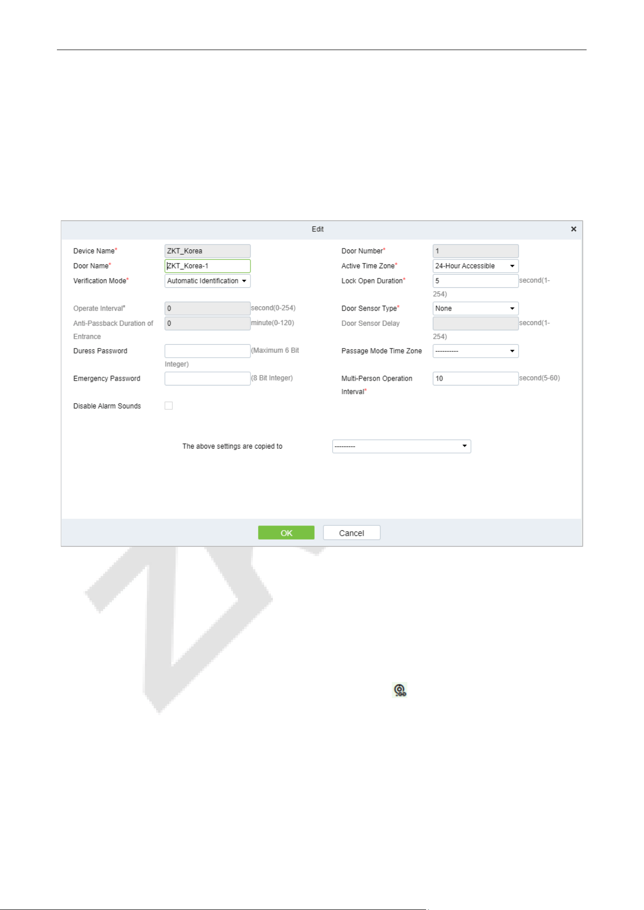
10.2 Door
1. In the Access Control module, select [Devices] > [Door].
2. In the management interface of the door, click the [Edit] button in the door operation bar to pop up
the door parameter setting box.
3. In the door parameter setting interface, fill in the corresponding parameters according to the addition
requirements, as shown in figure below.
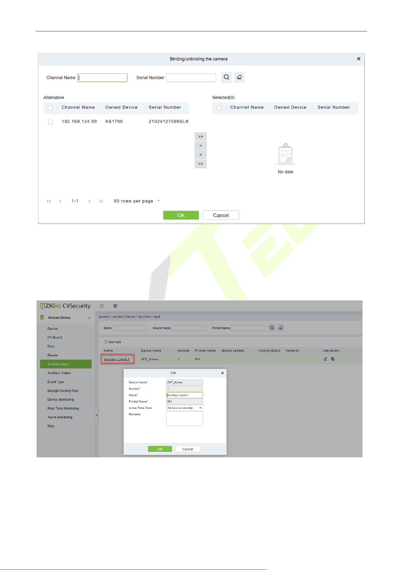
10.3 Reader
1. In the Access Control module, choose [Device] > [Reader].
2. In the Operation column of the corresponding Reader, click . The bind/unbind camera page is
displayed.
3. On the Select Reader screen, set the Reader as required, as shown in figure below.
InBioPC Series User Manual
Page | 42 Copyright©2025 ZKTECO CO., LTD. All rights reserved.
10.4 Auxiliary Input
1. Click [Access Device] > [Auxiliary Input] on the Action Menu, to access below shown interface.
2. Click on [Name] or [Edit] to modify the parameters as shown below:
3. Click [OK] to save the name and remark and exit.
InBioPC Series User Manual
Page | 43 Copyright©2025 ZKTECO CO., LTD. All rights reserved.
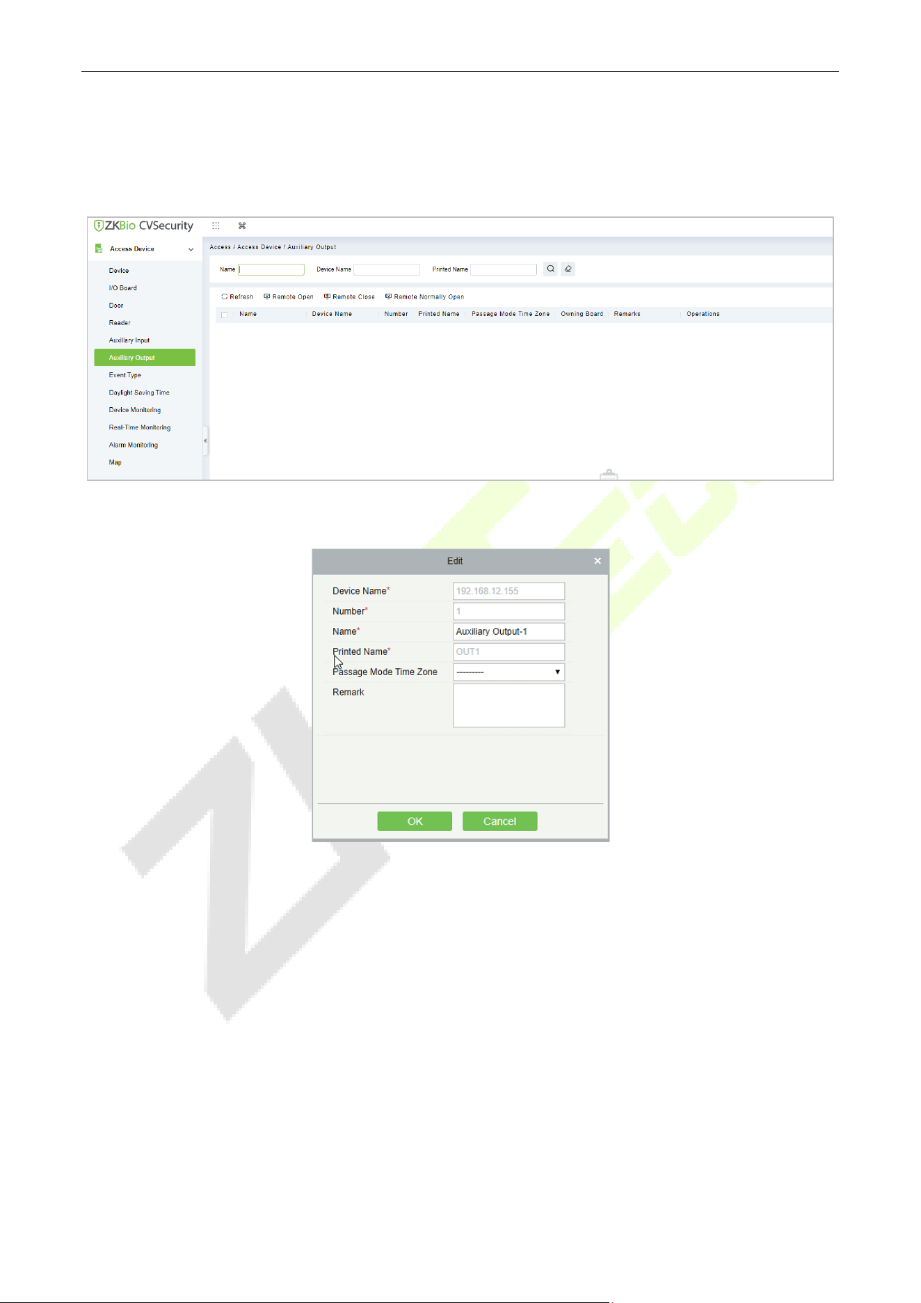
10.5 Auxiliary Output
1. Click [Access Device] > [ Auxiliary Output] on the Action Menu to access the following interface:
2. Click [Edit] to modify the parameters.
3. Click [OK] to save the name and remark and exit.
InBioPC Series User Manual
Page | 44 Copyright©2025 ZKTECO CO., LTD. All rights reserved.
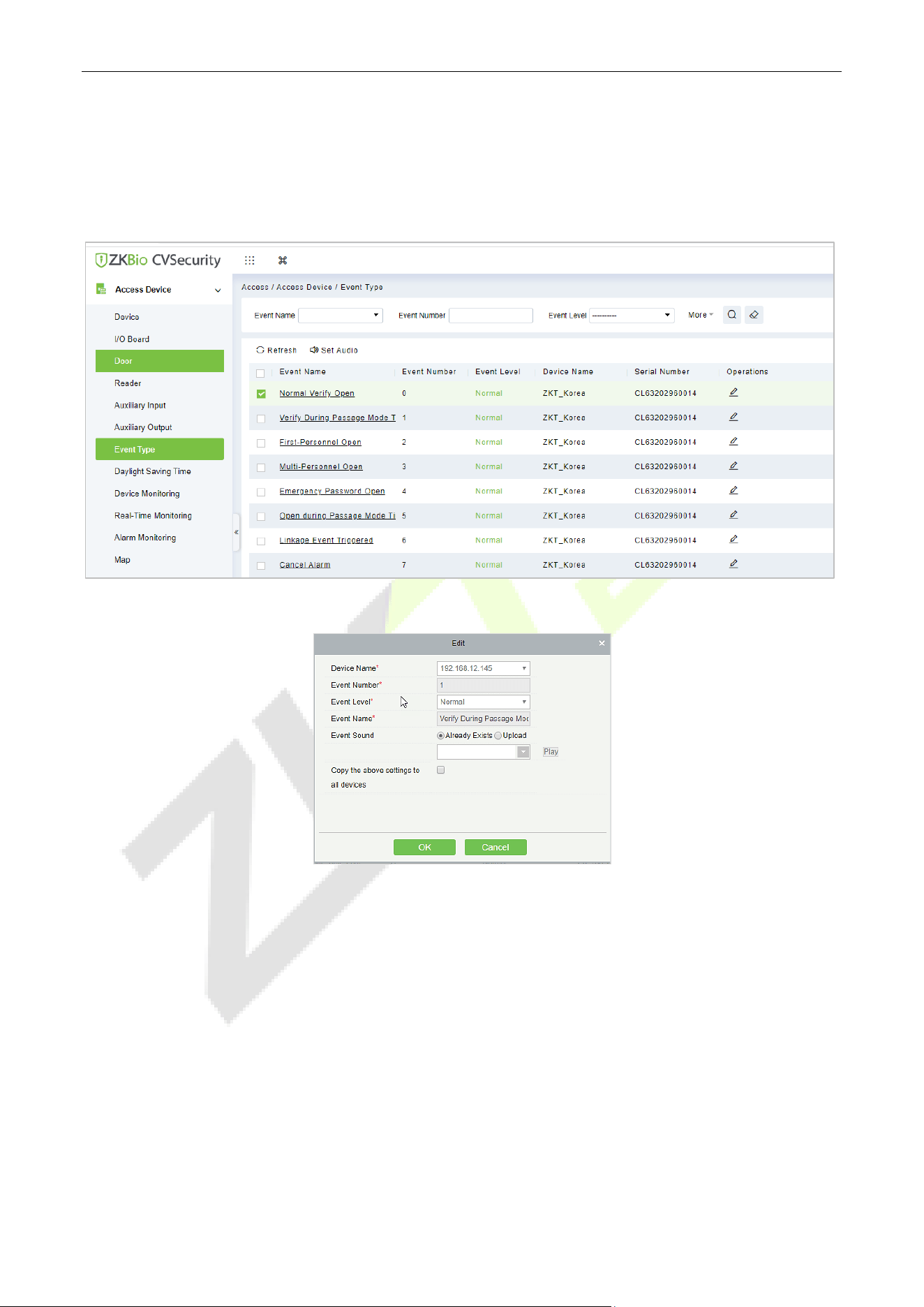
10.6 Event Type
1. Click [Access Device] > [Event] to access the following page:
2. Click [Edit] or click the event type name to edit.
InBioPC Series User Manual
Page | 45 Copyright©2025 ZKTECO CO., LTD. All rights reserved.
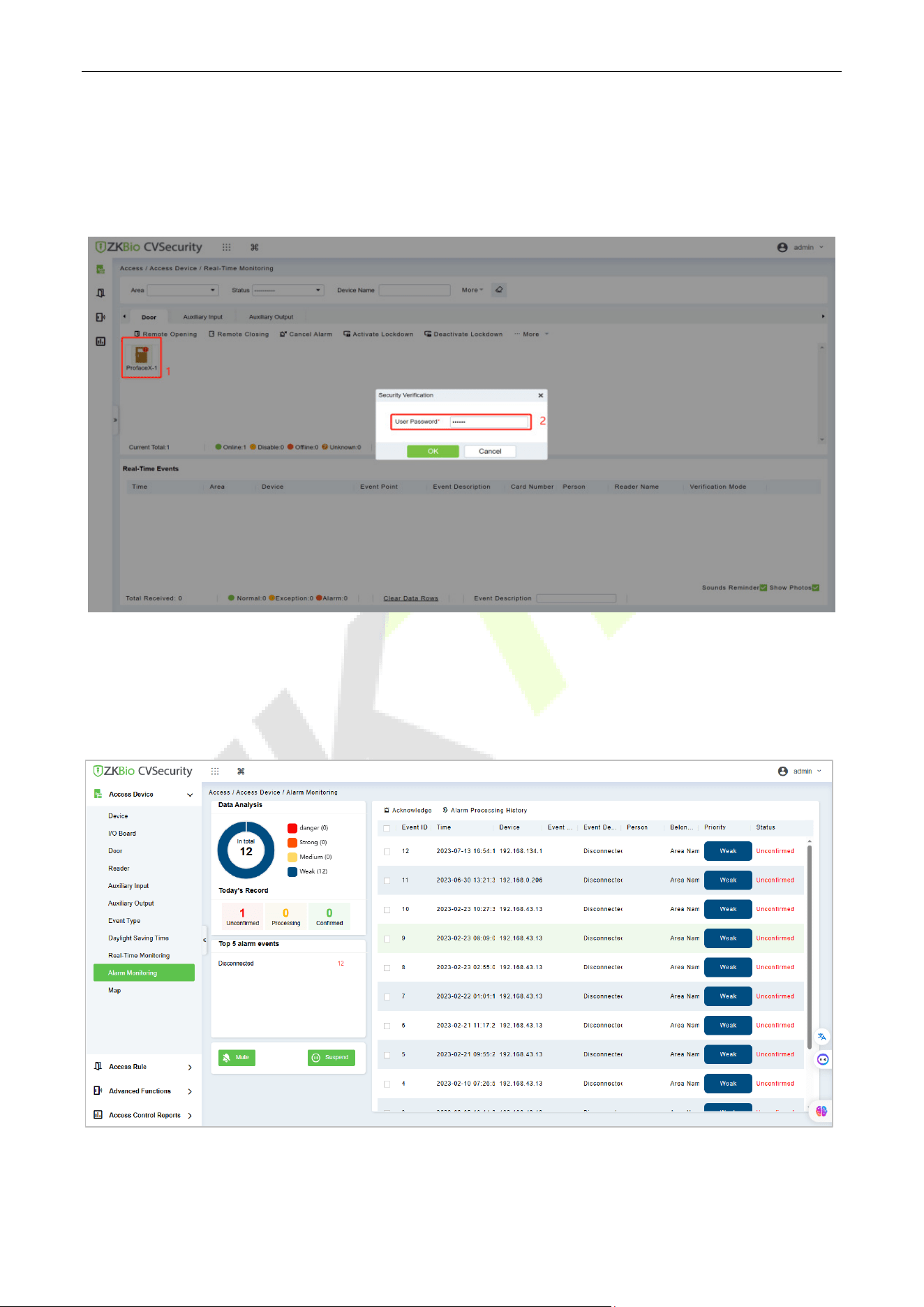
10.7 Real-Time Monitoring
1. In the Access Control module, choose [Access Control Device] > [Real-time Monitoring].
2. Check whether the icon status of the added device is online.
10.8 Alarm Monitoring
It will monitor the status and real-time events of doors under the access control panels in the system in
real-time, including normal events and abnormal events.
InBioPC Series User Manual
Page | 46 Copyright©2025 ZKTECO CO., LTD. All rights reserved.
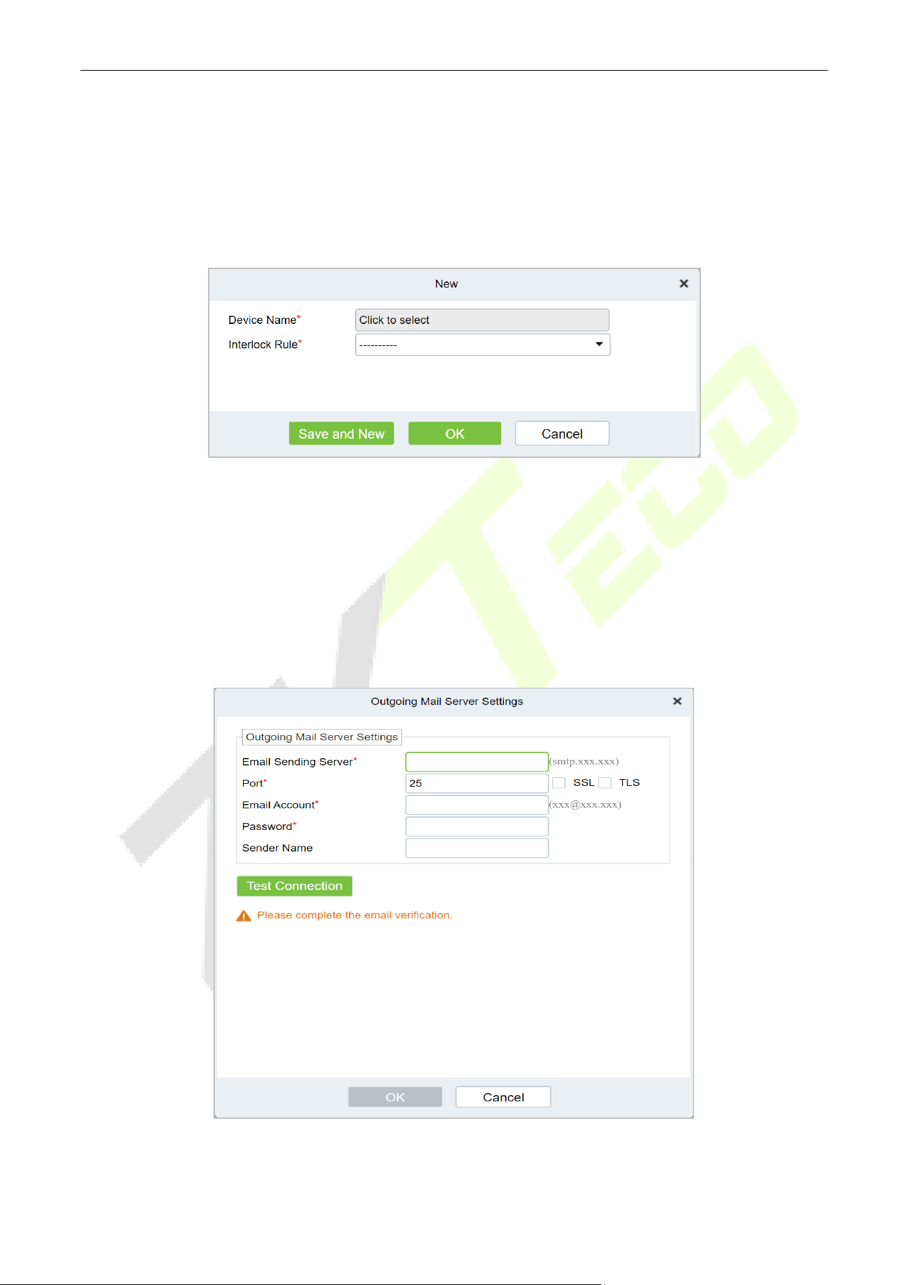
10.9 Interlock
Set interlock control between two or more doors on the access controller device: To verify the opening of
a door, ensure that all other doors interlocked with the door are closed; otherwise, the door cannot be
opened. In the Access Control module, choose [Access Control] > [Interlock] and click [New].
10.10 Linkage
The use method and scenario of linkage are flexible. After a specific event is triggered by an input point in
the Access Control system, a linkage action will be generated at the specified output point to control
events such as verification opening, alarm and abnormality in the system. Add Settings for binding
cameras to access control devices, input points, output points, and reader.
InBioPC Series User Manual
Page | 47 Copyright©2025 ZKTECO CO., LTD. All rights reserved.
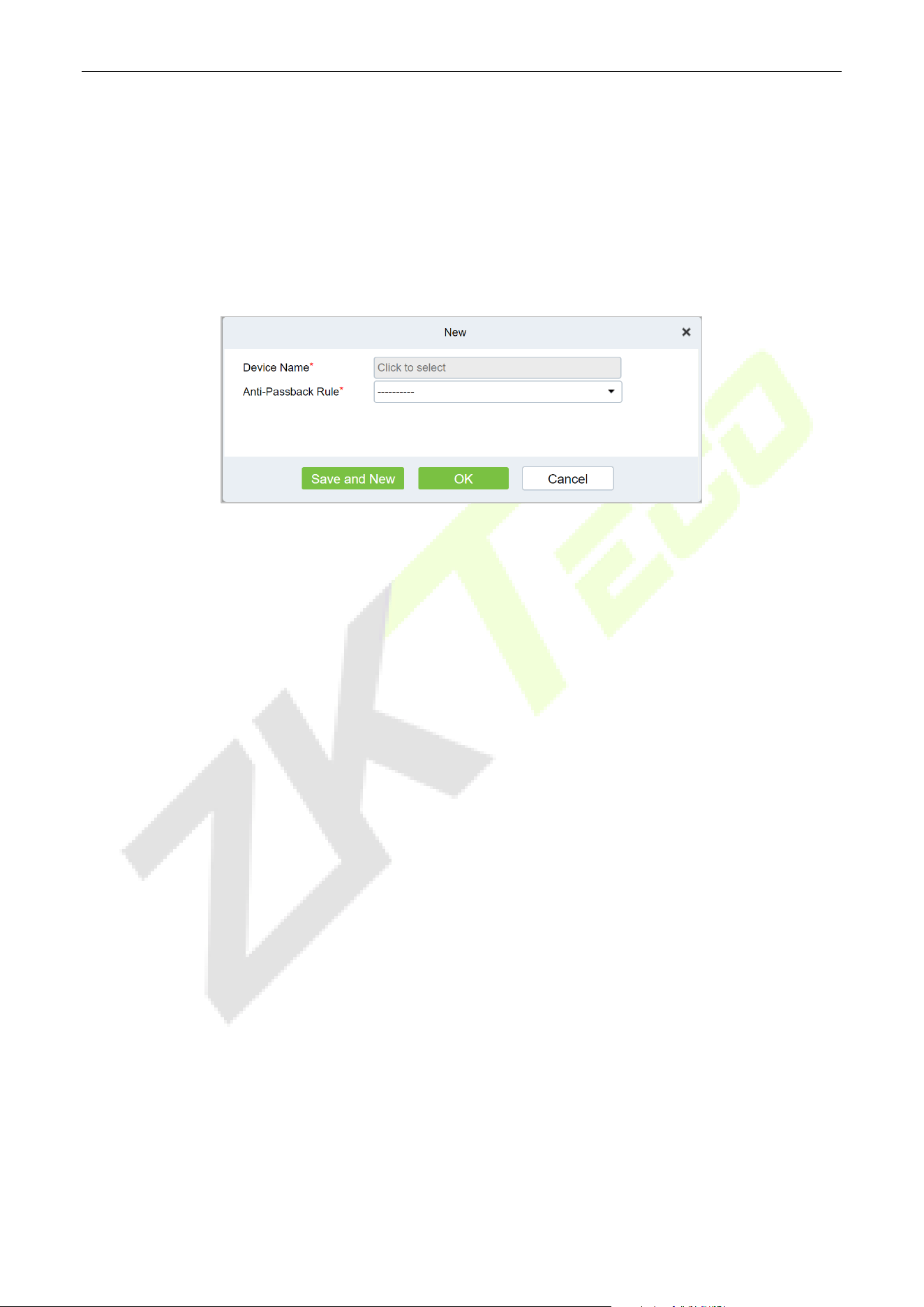
10.11 Anti-Passback
Some occasions require the personnel that brush card to verify, brush card to come in from a door must
brush card to go out from another door, brush card record must enter a strict correspondence. This
function can be used when users enable it in the settings. It is generally used in special units, scientific
research, bank vaults and other occasions. In the Access Control module, choose [Access Control] >
[Anti-Passback] and click [New].
For more detailed information on the use of the ZKBio CVSecurity, please refer to the ZKBio CVSecurity User
Manual.

InBioPC Series User Manual
Page | 48 Copyright©2025 ZKTECO CO., LTD. All rights reserved.
Appendix 1
Privacy Policy
Notice:
To help you better use the products and services of ZKTeco (hereinafter referred as “we”, “our”, or “us”) a
smart service provider, we consistently collect your personal information. Since we understand the
importance of your personal information, we took your privacy sincerely and we have formulated this
privacy policy to protect your personal information. We have listed the privacy policies below to precisely
understand the data and privacy protection measures related to our smart products and services.
Before using our products and services, please read carefully and understand all the rules and
provisions of this Privacy Policy. If you do not agree to the relevant agreement or any of its terms,
you must stop using our products and services.
I. Collected Information
To ensure the normal product operation and help the service improvement, we will collect the
information voluntarily provided by you or provided as authorized by you during registration and
use or generated as a result of your use of services.
1. User Registration Information: At your first registration, the feature template (Fingerprint
template/Face template/Palm template) will be saved on the device according to the device
type you have selected to verify the unique similarity between you and the User ID you have
registered. You can optionally enter your Name and Code. The above information is necessary
for you to use our products. If you do not provide such information, you cannot use some
features of the product regularly.
2. Product information: According to the product model and your granted permission when you
install and use our services, the related information of the product on which our services are
used will be collected when the product is connected to the software, including the Product
Model, Firmware Version Number, Product Serial Number, and Product Capacity Information.
When you connect your product to the software, please carefully read the privacy policy
for the specific software.
II. Product Security and Management
1. When you use our products for the first time, you shall set the Administrator privilege before
performing specific operations. Otherwise, you will be frequently reminded to set the
Administrator privilege when you enter the main menu interface. If you still do not set the

InBioPC Series User Manual
Page | 49 Copyright©2025 ZKTECO CO., LTD. All rights reserved.
Administrator privilege after receiving the system prompt, you should be aware of the
possible security risk (for example, the data may be manually modified).
2. All the functions of displaying the biometric information are disabled in our products by default.
You can choose Menu > System Settings to set whether to display the biometric information. If
you enable these functions, we assume that you are aware of the personal privacy security risks
specified in the privacy policy.
3. Only your user ID is displayed by default. You can set whether to display other user verification
information (such as Name, Department, Photo, etc.) under the Administrator privilege. If you
choose to display such information, we assume that you are aware of the potential
security risks (for example, your photo will be displayed on the device interface).
4. The camera function is disabled in our products by default. If you want to enable this function
to take pictures of yourself for attendance recording or take pictures of strangers for access
control, the product will enable the prompt tone of the camera. Once you enable this function,
we assume that you are aware of the potential security risks.
5. All the data collected by our products is encrypted using the AES 256 algorithm. All the data
uploaded by the Administrator to our products are automatically encrypted using the AES 256
algorithm and stored securely. If the Administrator downloads data from our products, we
assume that you need to process the data and you have known the potential security risk. In
such a case, you shall take the responsibility for storing the data. You shall know that some data
cannot be downloaded for sake of data security.
6. All the personal information in our products can be queried, modified, or deleted. If you no
longer use our products, please clear your personal data.
III. How We Handle Personal Information of Minors
Our products, website and services are mainly designed for adults. Without consent of parents or
guardians, minors shall not create their own account. If you are a minor, it is recommended that you
ask your parents or guardian to read this Policy carefully, and only use our services or information
provided by us with consent of your parents or guardian.
We will only use or disclose personal information of minors collected with their parents' or
guardians' consent if and to the extent that such use or disclosure is permitted by law or we have
obtained their parents' or guardians' explicit consent, and such use or disclosure is for the purpose
of protecting minors.

InBioPC Series User Manual
Page | 50 Copyright©2025 ZKTECO CO., LTD. All rights reserved.
Upon noticing that we have collected personal information of minors without the prior consent
from verifiable parents, we will delete such information as soon as possible.
IV. Others
You can visit https://www.zkteco.com/en/index/Index/privacy_protection.html to learn more about
how we collect, use, and securely store your personal information. To keep pace with the rapid
development of technology, adjustment of business operations, and to cope with customer needs,
we will constantly deliberate and optimize our privacy protection measures and policies. Welcome
to visit our official website at any time to learn our latest privacy policy.
InBioPC Series User Manual
Page | 51 Copyright©2025 ZKTECO CO., LTD. All rights reserved.
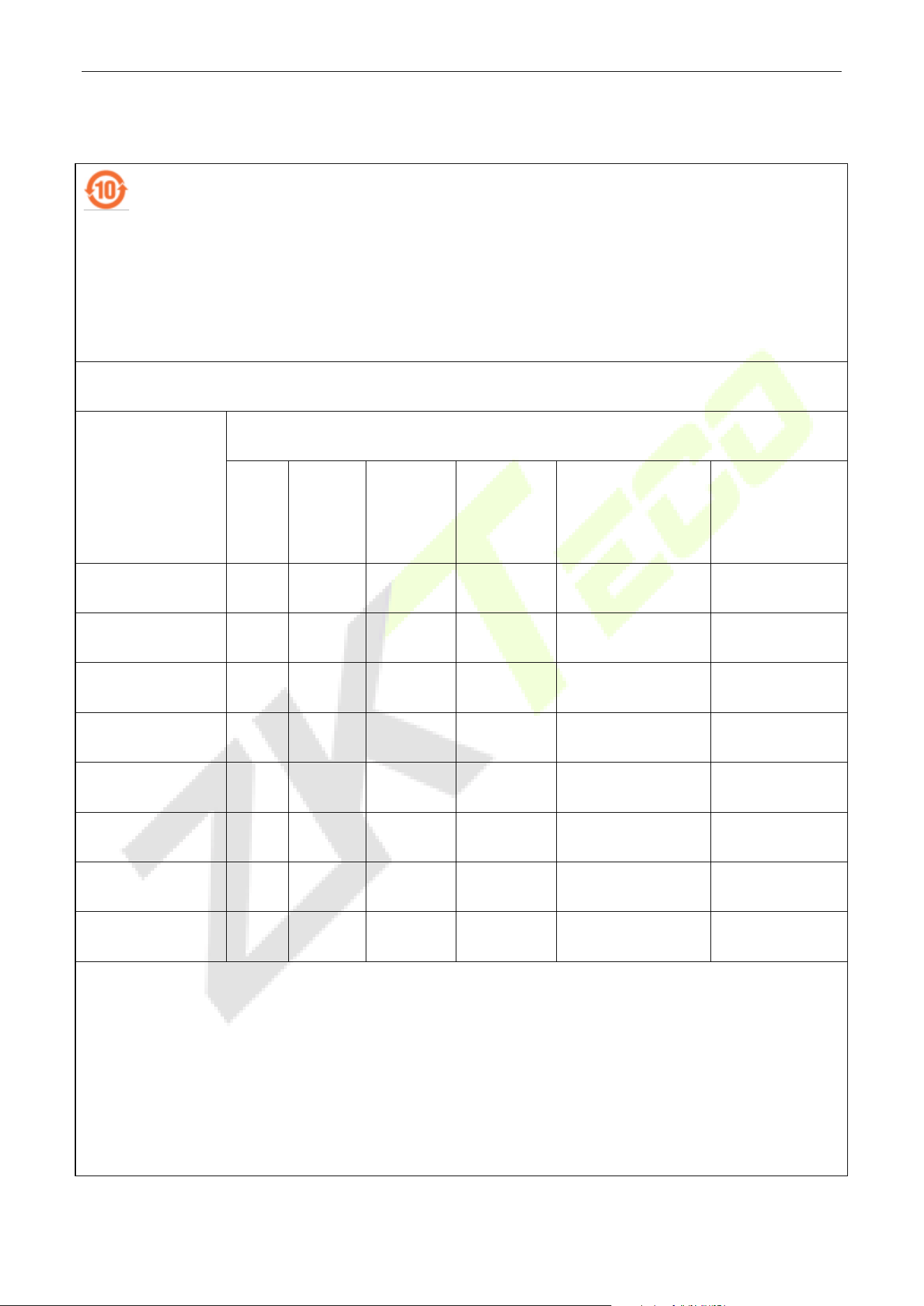
Eco-friendly Operation
The product's "eco-friendly operational period" refers to the time during which this product
will not discharge any toxic or hazardous substances when used in accordance with the
prerequisites in this manual.
The eco-friendly operational period specified for this product does not include batteries or
other components that are easily worn down and must be periodically replaced. The
battery's eco-friendly operational period is 5 years.
Hazardous or Toxic substances and their quantities
Component Name
Hazardous/Toxic Substance/Element
Lead
(Pb)
Mercury
(Hg)
Cadmium
(Cd)
Hexavalent
Chromium
(Cr6+)
Polybrominated
Biphenyls
(PBB)
Polybrominated
Diphenyl Ethers
(PBDE)
Chip Resistor
×
○ ○ ○ ○ ○
Chip Capacitor ×
○ ○ ○ ○ ○
Chip Inductor ×
○ ○ ○ ○ ○
Diode ×
○ ○ ○ ○ ○
ESD component
×
○ ○ ○ ○ ○
Buzzer
×
○ ○ ○ ○ ○
Adapter ×
○ ○ ○ ○ ○
Screws
○
○ ○
×
○ ○
This table is prepared in accordance with the provisions of SJ/T 11364.
○ indicates that the total amount of toxic content in all the homogeneous materials is below the limit as
specified in GB/T 26572.
× indicates that the total amount of toxic content in all the homogeneous materials exceeds the limit as
specified in GB/T 26572.
Note: 80% of this product’s components are manufactured using non-toxic and eco-friendly materials. The
components which contain toxins or harmful elements are included due to the current economic or
technical limitations which prevent their replacement with non-toxic materials or elements.

ZKTeco Industrial Park, No. 32, Industrial Road,
Tangxia Town, Dongguan, China.
Phone : +86 769 - 82109991
Fax : +86 755 - 89602394
www.zkteco.com
Copyright © 2025 ZKTECO CO., LTD. All Rights Reserved.


