
See page 3
REVISED BULLETIN
SERVICE PARTS LIST
BULLETIN NO.
STARTING
SERIAL NO.
WIRING INSTRUCTION
DATE
SPECIFY CATALOG NO. AND SERIAL NO. WHEN ORDERING PARTS
CATALOG NO.
54-05-0135
M18 FUEL™ 6 GALLON WET/DRY VACUUM
0910-20
L63A
June 2023
0
00
EXAMPLE:
Component Parts (Small #) Are Included
When Ordering The Assembly (Large #).
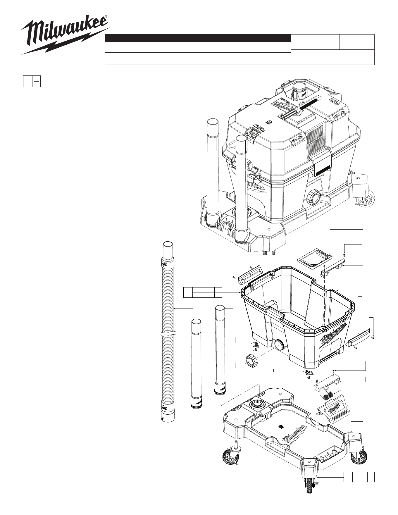
FIG. PART NO. DESCRIPTION OF PART NO. REQ.
13 49-90-1987 Wand (Includes 1) (2)
14 --------------- 6 Gallon Tank (See item 73) (1)
15 42-16-2700 Bag Holder Attachment (1)
16 42-16-2705 Bag Holder Screw-In Attachment (1)
17 44-85-0252 Tank Foot #1 (2)
18 05-74-1044 M4 x 12mm Flange T-15 Screw (10)
19 --------------- Cart Base (1)
20 14-04-0130 Caster (4)
21 44-85-0253 Tank Foot #2 (2)
22 31-01-3035 Drain Cap (1)
23 --------------- Pedal Cover (1)
24 40-50-3925 Spring (1)
25 05-74-1012 8-18 x 16mm Hi-Low T-15 Screw (2)
26 45-06-0589 Tank Handle (2)
27 45-24-3100 Pedal (1)
71 49-90-1996 Hose Assembly (1)
72 0923-20 Cart Base Assembly (1)
73 0922-20 Tank Assembly (1)
13
(2x)
21
(2x)
18
(2x)
22
71
20
(4x)
17
(2x)
18
(2x)
72
19 20 23
24 25 27
73
14 15 16 17
18 21 22 26
15
18
(2x)
16
14
26
(2x)
18
(4x)
25
(2x)
23
24
27
19
See page two for Head Assembly service parts
MILWAUKEE TOOL
l
www.milwaukeetool.com
13135 W. LISBON RD., BROOKFIELD, WI 53005
Drwg.8
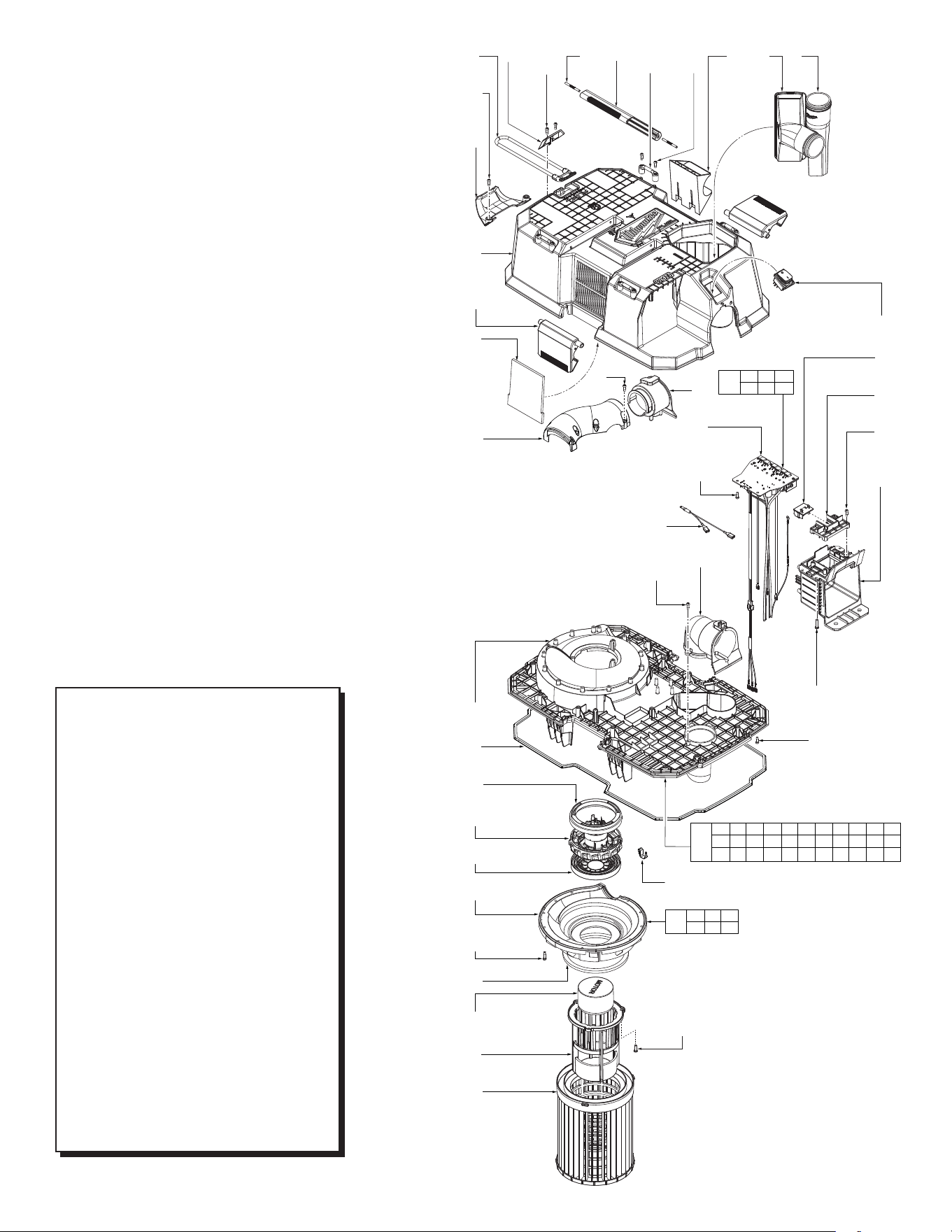
FIG. PART NO. DESCRIPTION OF PART NO. REQ.
1 49-90-1988 Crevice Tool (1)
2 31-44-7015 Carrying Handle (1)
4 49-90-2011 Floor Utility Nozzle (1)
6 31-17-0520 Hose Clip (1)
7 31-44-7017 Knurled Pin (2)
8 42-28-0560 Bungee Holder (1)
9 14-37-0185 Bungee Hose Strap (1)
10 31-70-0170 Hose Rest Bracket (1)
11 --------------- Head (1)
12 --------------- PCBA (1)
25 05-74-1011 8-18 x 12mm Hi-Lo T-15 Screw (53)
29 --------------- On-OSwitch (1)
30 45-58-0285 Mounting Cleat (Set of 1) (4)
31 58-95-0075 Foam, Head (1)
32 31-01-3030 Exhaust Cover (1)
33 --------------- Battery Terminal Block (2)
34 31-01-3020 Battery Terminal Cap (1)
39 05-74-1042 #7-18 x 19mm Plastite T-20 Screw (4)
41 43-33-0480 Inlet Elbow (1)
42 31-05-0735 Exhaust Port (1)
43 45-06-0585 Tank Buckle (2)
44 31-01-1008 Mid-Frame (1)
45 44-66-5364 Motor Isolator-Upper (1)
46 31-50-9000 Motor Assembly (1)
47 --------------- Lower Volute (1)
48 31-55-0245 Motor Isolator-Lower (1)
49 --------------- Lower VoluteFilter Seal (1)
50 --------------- Ball Float (1)
51 --------------- Ball Float Cage (1)
52 49-90-1978
LargeWet/DryVacuumHighEciencyFilter
(1)
53 05-74-1012 8-18 x 16mm Hi-Lo T-20 Screw (12)
54 22-56-0061 Y-Strap (1)
70 31-44-0461 Battery Housing with Left Rail (1)
74 0911-20 Head Assembly (1)
75 31-15-1987 Lower Volute/Float Cage Assembly (1)
76 23-66-6520 Electronics Assembly (1)
77 45-06-0587 Mid-Frame Gasket (1)
78 45-56-0033 Motor Ground Strap (1)
49-90-1979
Fleece Dust Bags (Pkg. of 5) (Not Included)
(1)
12-20-0542 Service Nameplate (Not Shown) (1)
25
(2x)
8
9
25
(2x)
10
11
43
(2x)
31
32
44
77
45
46
48
47
53
(12x)
49
50
51
52
7
(2x)
2
30
(4x)
25
(8x)
6
4
1
25
(6x)
42
12
25
(4x)
41
25
54
(3x)
29
33
34
25
(4x)
70
39
(4x)
25
(21x)
75
47 49 50
51 53
76
12 25 29
33 34 70
74
2 6 7 8 9 10 11 12 25 29 30
31 32 33 34 39 41 42 43 44 45 46
47 49 50 51 70 75 76 77 78
25
(3x)
78
0910-20
M18™ FUEL™ 6 Gallon Wet/Dry Vacuum
Consists of the following:
1.875" Hose and Attachments
0911-20 Motor Head Assembly (1 Battery)
0922-20 6 Gallon Tank Assembly
0923-20 Base Cart Assembly
0920-20
M18™ FUEL™ 9 Gallon Wet/Dry Vacuum
Consists of the following:
1.875" Hose and Attachments
0921-20 Motor Head Assembly (2 Batteries)
0912-20 9 Gallon Tank Assembly
0923-20 Base Cart Assembly
0930-20
M18™ FUEL™ 12 Gallon Wet/Dry Vacuum
Consists of the following:
2.5" Hose and Attachments
0921-20 Motor Head Assembly (2 Batteries)
0932-20 12 Gallon Tank Assembly
0933-20 Premium Cart Assembly
NOTE:
Motor Head Assemblies, Tank Assemblies
and Cart Assemblies listed above are all
interchangeable. The 120V AC Motor Head
Assembly 0931-20 is also interchangeable
with the tank and cart assemblies.
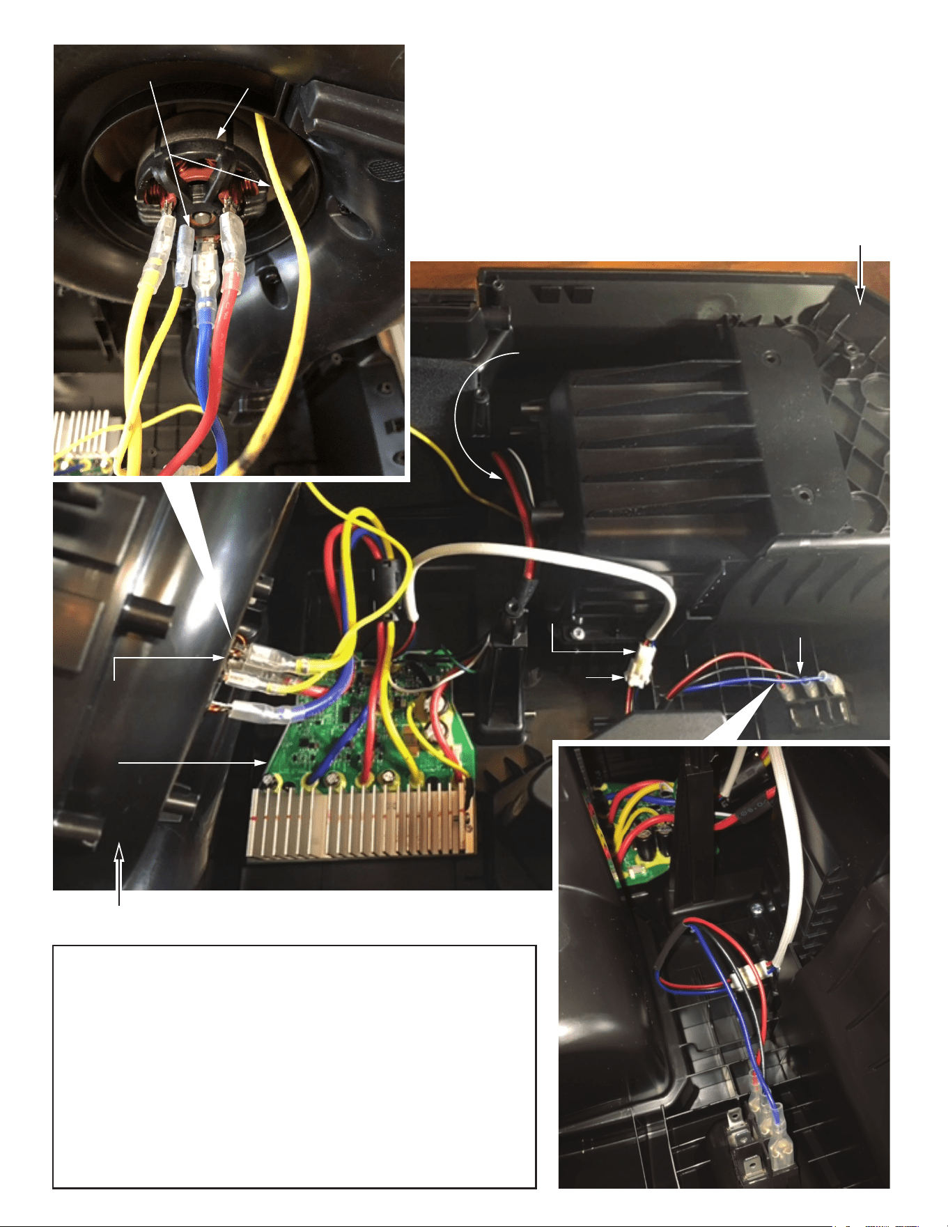
MOTOR
Y-Strap
Connect Yellow Ground PCBA Wire to Y-strap. Connect Y-strap to Motor Ground
Strap and motor ground terminal/tab.
Connect Red PCBA wire to terminal labeled RED on the upper right of motor.
Connect Yellow PCBA wire to terminal labeled YLW on the upper left of motor.
Connect Blue PCBA wire to terminal labeled BLU on the bottom of motor.
Pull on all wires terminated at the motor to ensure proper connection.
Join PCBA wires and On-Off Switch wires by inserting connector ends together.
PCBA WIRES
TO MOTOR
PCBA
WIRES FROM BATTERY
TERMINAL BLOCK TO PCBA
(BATTERY TERMINAL BLOCK
NOT SHOWN)
ON-OFF
SWITCH
PCBA
CONNECTOR
ON-OFF
SWITCH
CONNECTOR
HEAD ASSEMBLY
MID-FRAME
As an aid to reassembly, take notice of wire routings and position in wire guides
and traps while dismantling tool.
Be sure that all components of electronics kit are seated firmly and squarely in
housing recesses.
Avoid pinched wires, be sure that all wires and sleeves are pressed completely
down in wire traps.
Prior to securing mid-frame onto the head, be sure that there are no interferences.
Before installing the battery, check for proper functionality of switch.
Install battery and depress switch triggers to assure tool is operating properly.