
User Manual
VT07-B26L-W
Version: 1.0
Due to the regular upgrades of systems and products, ZKTeco could not guarantee exact
consistency between the actual product and the written information in this manual.
REMARK
Please follow the user manual for correct installation and testing. If there is any doubt
please call our tech-supporting and customer center.
Our company applies ourselves to reformation and innovation of our products. No
extra notice for any change. The illustration shown here is only for reference. If there is
any difference, please take the actual product as the standard.
The product and batteries must be handled separately from household waste. When
the product reaches the end of service life and needs to be discarded, please contact
the local administrative department and put it in the designated collection points in
order to avoid the damage to the environment and human health caused by any
disposal. We encourage recycling and reusing the material resources.

CATALOG
PRODUCT FEATURE ................................................................ - 1 -
TECHNICAL PARAMETER ....................................................... - 1 -
PACKAGE CONTENT ................................................................ - 2 -
OVERVIEW .................................................................................. - 3 -
BASIC OPERATION ................................................................... - 4 -
DEVICE SETTING .................................................................... - 13 -
WEB SETTING .......................................................................... - 19 -
SYSTEM DIAGRAM ................................................................ - 34 -
DEVICE WIRING ...................................................................... - 35 -
INSTALLATION ....................................................................... - 37 -
TROUBLESHOOTING ............................................................ - 39 -
SAFETY INSTRUCTION ......................................................... - 40 -

- 1 -
PRODUCT FEATURE
1. Easy configuration
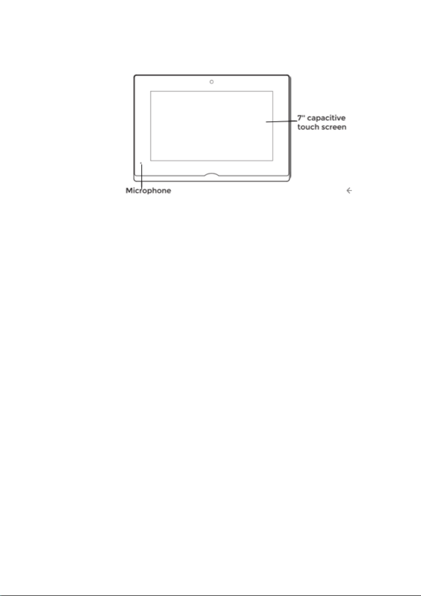
2. 7-inch capacitive touch screen
3. Powered by PoE or power adapter (DC12V/2A)
4. Support SIP 2.0 protocol, easy integration with other SIP devices
5. Easy integration with elevator control system
6. Support monitoring 8 IP cameras
TECHNICAL PARAMETER
System: Linux
RAM: 64 MB
ROM: 128 MB
Front Panel: Plastic
Power Supply: PoE (802.3af) or DC 12V/2A
Standby Power: 1.5 W
Rated Power: 9 W
Ethernet Port: 1 x RJ45, 10/100 Mbps adaptive
Resolution: 1024 x 600
Working Temperature: -10℃ to +55℃
Storage Temperature: -40℃ to +70℃
Working Humidity: 10% to 90% (non-condensing)
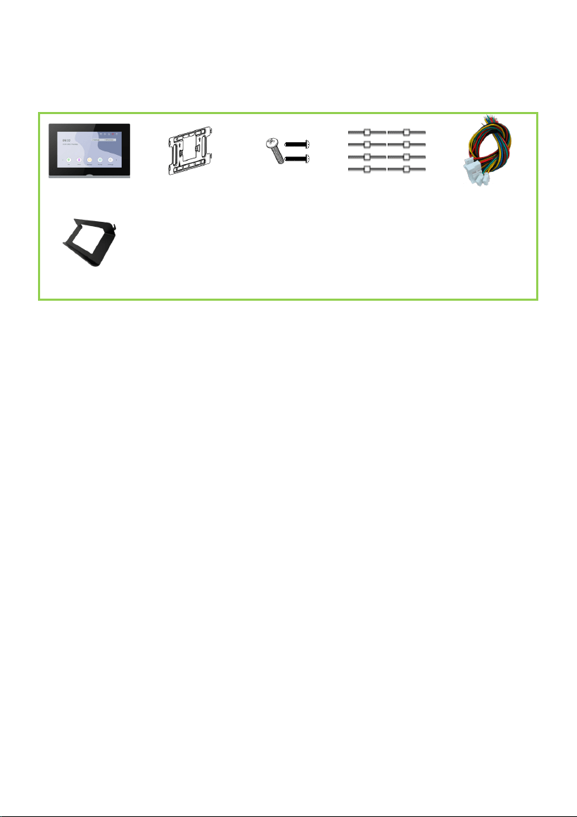
- 2 -
PACKAGE CONTENT
MODEL: VT07-B26L-W
VT07-B26L-W Wiring Cover PM4×20 (2 pcs) Diode (8 pcs) Wires
Desktop Stand
(Optional)
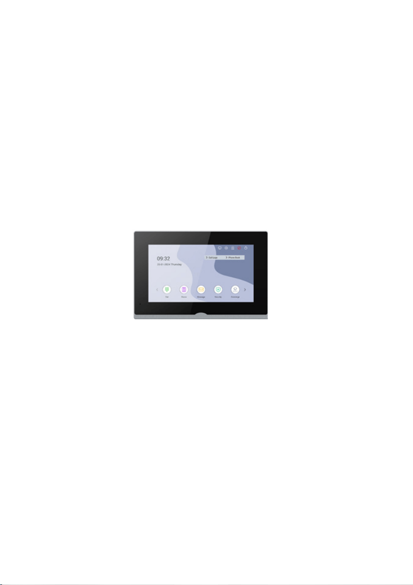
- 3 -
OVERVIEW
- 4 -
BASIC OPERATION
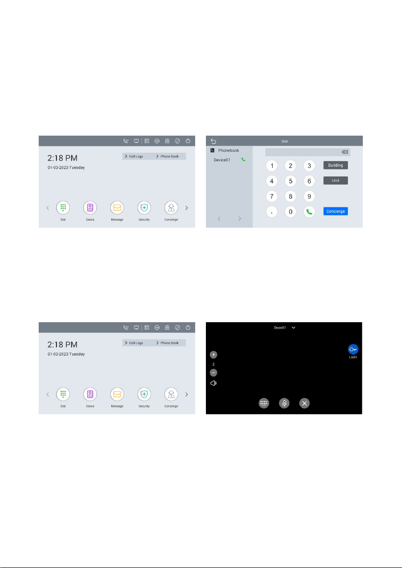
1. Call
Go to Dial and enter Building number + Building + Unit number + Unit + Room
number + dial icon to call Indoor Monitor (such as 1 + Building + 1 + Unit + 1111 + Dial
button). Or you can press Concierge here to call Master Station.
2. Doors
Click Doors icon on Indoor Monitor’s homepage to monitor Door Station. You can
unlock by clicking door icon or switch to monitor other devices by clicking arrow or the
name above.
3. Message
Indoor Monitor can receive the messages sent by the CMS, Master Station or Indoor
Monitor. Up to 64 records can be received in SMS.
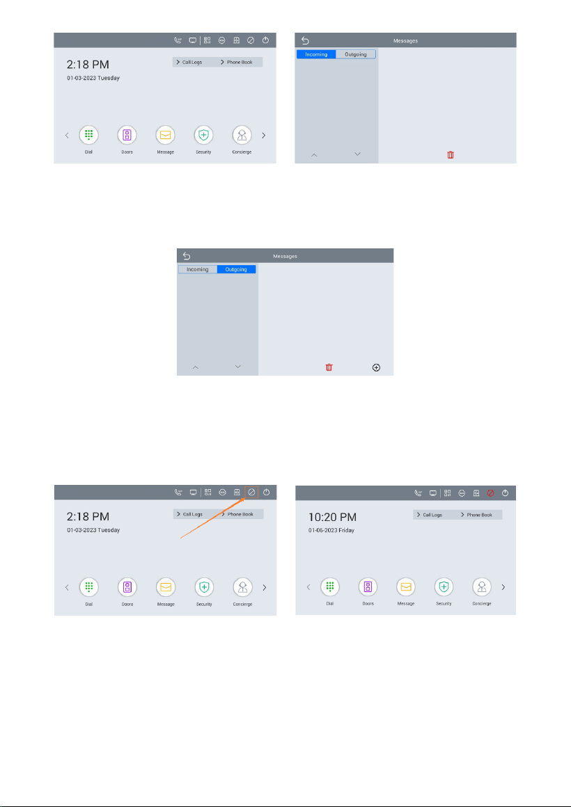
- 5 -
Click + icon on Outgoing page. Users can send message to Indoor Monitor or Master
Station. Before sending message, users need to fill in the receiver’s IP address on
Indoor Monitor webpage (Concierge IP in Intercom > Call column).
4. DND
Click DND icon on the right upper corner to enable do not disturb function. No calls
can call in. Users can set DND to turn on whole day or a period of time.
5. Cameras
On the 2
nd
homepage, click Cameras. Up to 8 IPC can be added. Users need to log in
Indoor Monitor’s webpage with account (user) and password (1234) to fill in cameras’
RTSP. You can switch to monitor other devices by clicking arrow or the name above.
You can also add more cameras by clicking the icon on the right upper corner.
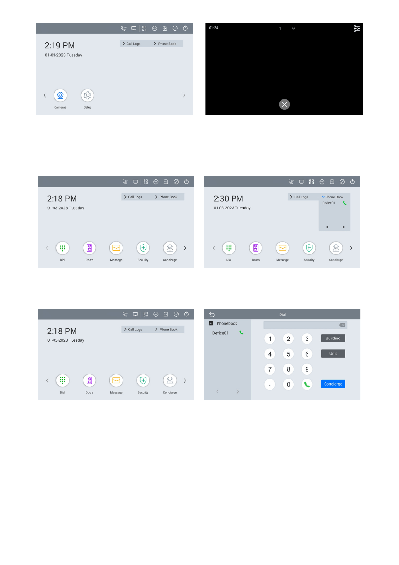
- 6 -
6. Phonebook
Click phone Book.
Or go to Dial > Phonebook. Select the name on the phonebook and press dial button
to call.
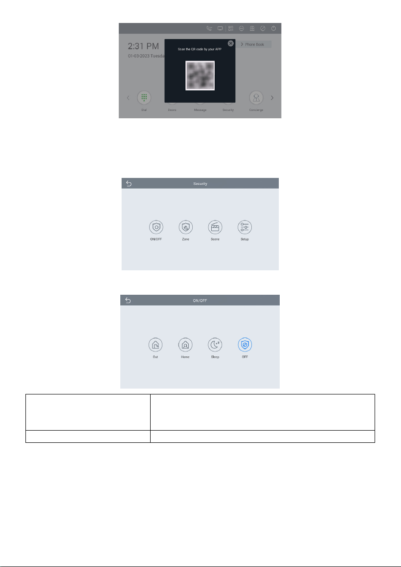
7. QR Code
Click QR Code and scan by Smart Life app to add this Indoor Monitor to your phone.
Only when the license is filled in Internet-connected Indoor Monitor, QR code will be
available.
- 7 -
8. Security
Security is for sensors. The default password is 1234.
8.1 ON/OFF
ON:
Click Out, Home, or Sleep icon to activate the scene
for alarm sensors, the icon on the main interface will
light up with a beep sound;
OFF:
Click OFF to disable scene;
- 8 -
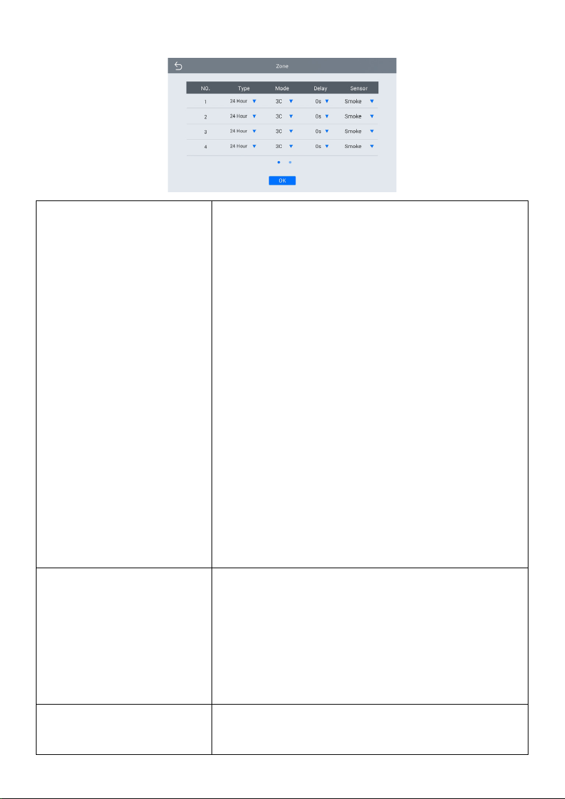
8.2 Zone
Type:
•
Normal: When users enable an alarm scene on the
On/Off page, Normal type alarm zone will be
activated after activation time.
o 100 seconds is the default activation time, it
means the alarm will be activated after 100
seconds.
o After 100s, once sensor is triggered, Indoor
Monitor will send this alarm to Master Station.
o But sometimes users don't want to send the
alarm to Master Station (maybe alarm by
mistake), users can set the Delay time, so they
can cancel the alarm in the Indoor Monitor
during this Delay time (PIR, Door, Window);
• Emergency: once Panic button is triggered, Indoor
Monitor will not initiate an alarm and only Master
Station will receive alarms secretly; 24 hours
standby even if the security is off (Panic, Pull
Cord);
• 24 Hour: Indoor Monitor will initiate an alarm and
Master Station will also receive alarms. 24 hours
standby even if the security is off (Smoke, Gas,
Flood);
Mode:
•
3C: for the sensor with 2.2KΩ resistance;
Regardless of the connection to NC or NO, the
alarm can be triggered normally;
• NO: normally open;
• NC: normally closed;
• BELL: in BELL mode, Master Station will not
receive any alarm. Indoor Monitor is regarded as a
doorbell receiver;
Delay:
Once sensor is triggered, Indoor Monitor will send
this alarm to Master Station, but users can terminate
the alarm sending to Master Station during the
- 9 -
delayed time set here. Delay setting is only effective
for Normal type (0s, 5s, 15s, 20s, 25s, 40s, 60s);
Sensor:
Sensor types (Smoke, Gas, PIR, Door, Window, Panic,
Flood, Pull Cord);
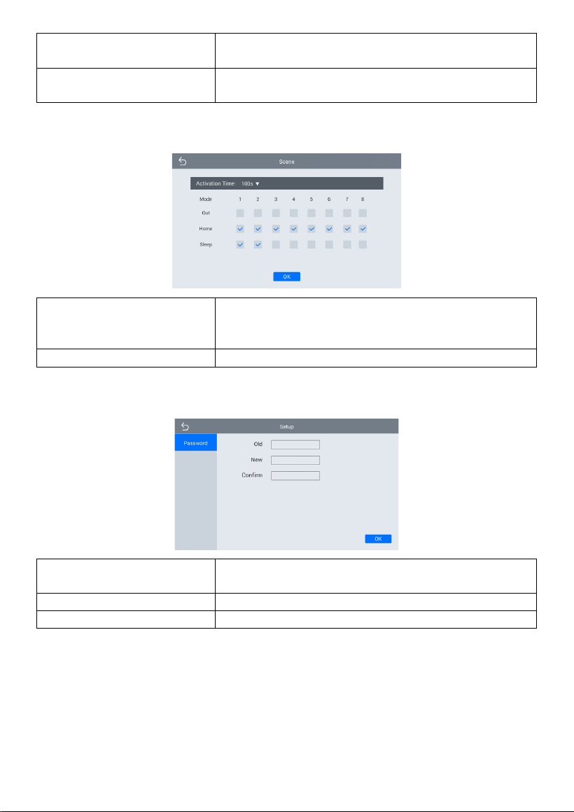
8.3 Scene
Activation Time:
Only after activation time, will scene be activated.
Activation time is only effective for Normal type
(NONE, 30s, 40s, 60s, 100s, and 300s);
Mode:
Tick to link sensors to Out, Home, or Sleep scene;
8.4 Setup
Old:
Current security password of the Device (Default
123456);
New:
New security password of the Device;
Confirm:
Confirm security password of the Device;
- 10 -
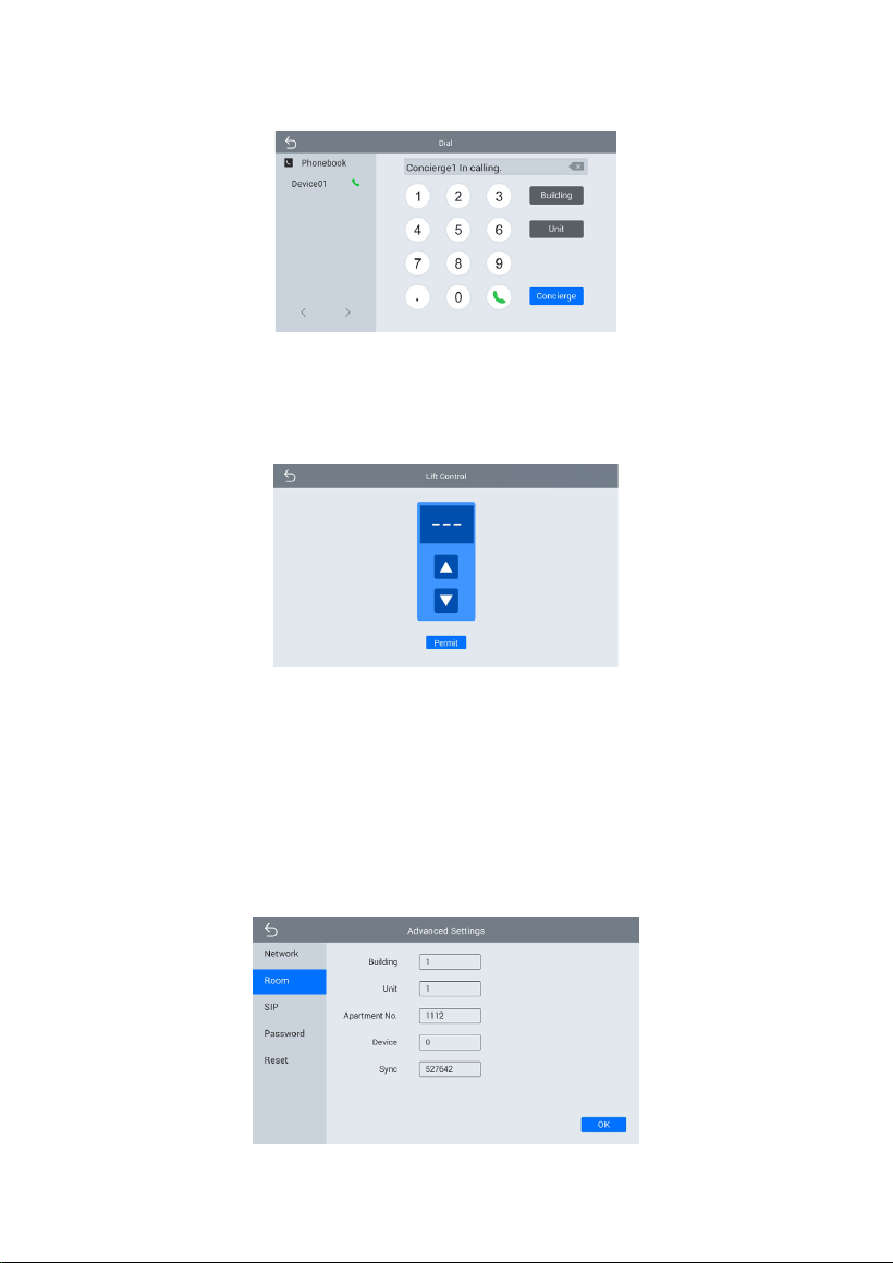
9. Concierge
Press the Concierge icon to call Master Station one by one.
10. Elevator
Press the Elevator icon to control elevator (Elevator Control Module is needed).
11. Add More Indoor Monitors
Keep Building, Unit, Apartment No., Sync the same as other Indoor Monitors, and
Device number should be different. The Device number can be from 0 to 9. But you
must have one Indoor Monitor’s Device number is 0 and keep it online because 0 here
stands for the main one.
- 11 -
Or go to Indoor Monitor’s webpage and find Ex Phone in Intercom > Call. Users can
directly extend to more Indoor Monitors by filling in sip:IP address (6 Max) such as
sip:192.168.68.90. (Please refer to WEB SETTING for the way to access to webpage)
12. SIP Setting
Users can directly configure SIP on the device’s Setup > More > SIP page.
13. SOS
Users can press SOS icon on the right upper corner to send SOS to Master Station.
Users can set the trigger time length on the webpage. If the time is set to 3s, users
need to press the SOS icon for 3s to send out SOS in case of a wrong operation alarm.
- 12 -
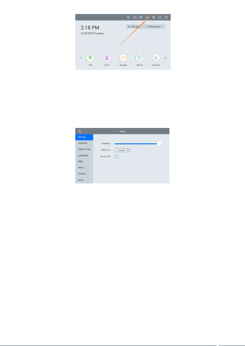
14. Screen Lock
Users can lock the screen by enabling Screen Lock on the device’s Setup > Display
page. The screen will be locked after screen off timeout (Unlock password is the
security password. The default password is 1234).
- 13 -
DEVICE SETTING
Connect Indoor Monitor and other devices to a network switch in the same LAN.
1. Display
Brightness:
Screen brightness adjustment;
Sleep Time:
Screen sleep time (15s, 30s, 1min, 2mins, 5mins,
20mins, 30mins);
Screen Lock:
The screen will be locked after screen off timeout
(Unlock password is security password. The default
password is 1234);
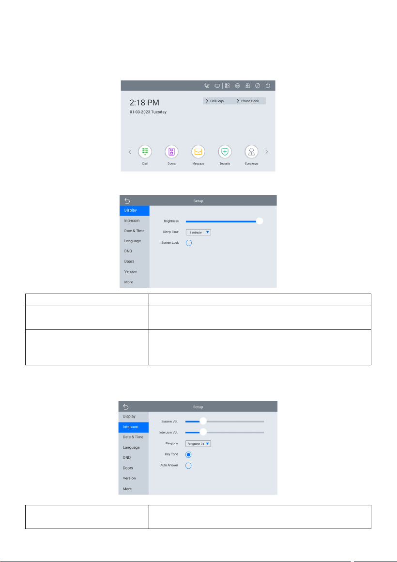
2. Intercom
System Vol:
Volume of System can be set from 1 to 6. Volume 6
is the maximum volume (Key tone);
- 14 -
Intercom Vol:
Volume of Intercom can be set from 1 to 6. Volume
6 is the maximum volume (Call volume);
Ringtone:
The ringing sound (Ringtone 01-04);
Key Tone:
The keytone (Enable or disable);
Auto Answer:
Pick up automatically when receiving a call;
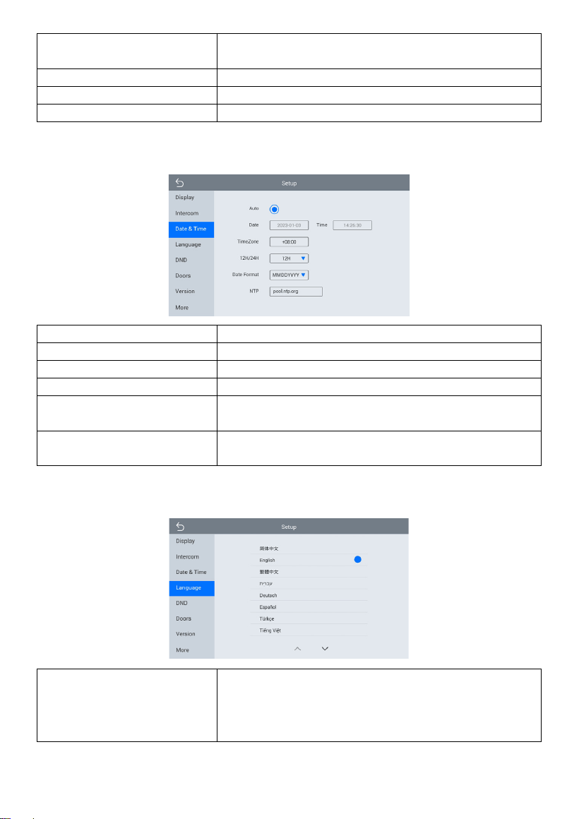
3. Date & Time
Auto:
Enable to synchronize computer time;
Date&Time:
Date and time can be set manually;
Time Zone:
A region that observes a uniform standard time;
12H/24H:
Select 12H or 24H format to display on the device;
Date Format:
3 time formats supported (YYYY-MM-DD, DD-MM-
YYYY, MM-DD-YYYY);
NTP:
Network Time Protocol (NTP) is a protocol used to
synchronize NTP time;
4. Language
Language:
16 languages supported (简体中文, English, 繁體中
文, תי ִרב ִﬠ, Deutsch, Español, Türk, Tiếng Việt,
Nederlands, Português, Polski, Русский, ﻲﺑرﻋ
,
Français, Italiano, slovenský);
- 15 -
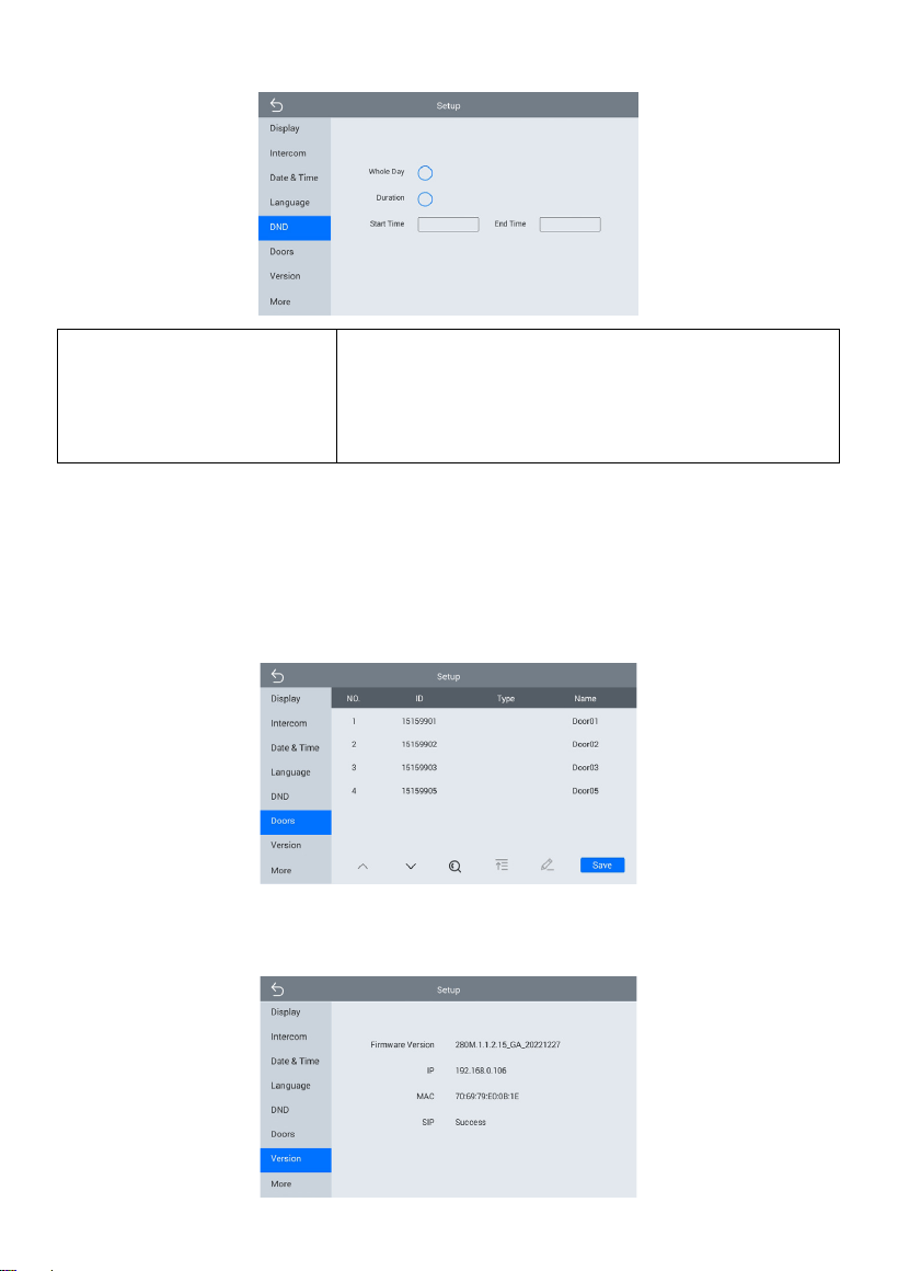
5. DND
DND:
DND is disabled by default.
Whole Day: when DND is enabled, it will reject calls
for the whole day.
Duration: when DND is enabled, it will reject calls
during this time.
6. Doors
You need to click search icon to add Door Stations to Indoor Monitor and click Save to
save before monitoring. Click funnel icon to pin the selected device to the top. Click
pen icon to edit devices.
7. Version
- 16 -
Firmware Version:
Firmware version of the device;
IP:
Current IP address of the device;
MAC:
MAC address of the device;
SIP:
Status of SIP registration of the device;
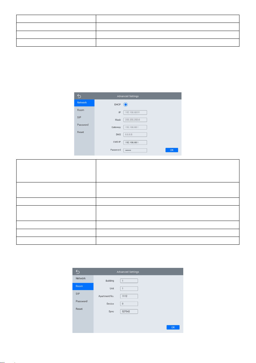
8. More > Network
The device network can be set to either DHCP or a static IP address. CMS parameters
should be configured here when you try to register this device to CMS.
DHCP:
Enable DHCP (Dynamic Host Configuration
Protocol) to dynamically distributing network
configuration parameters;
IP:
Configure Static IP address to manually distributing
network configuration parameters;
Mask:
Subnet mask;
Gateway:
A component that is part of two networks, which
use different protocols;
DNS:
Domain Name Server of the device;
CMS IP:
Server address of CMS;
Password:
Password you set for this device’s CMS registration;
9. More > Room
- 17 -
Building:
Number of the building (Range: 1-999);
Unit:
Number of the unit (Range: 0-99);
Apartment No.:
Number of the apartment (Range: 0-9899);
Device:
Number of the device (Range: 0-9);
Sync:
A number used to synchronize to other Indoor
Monitors;
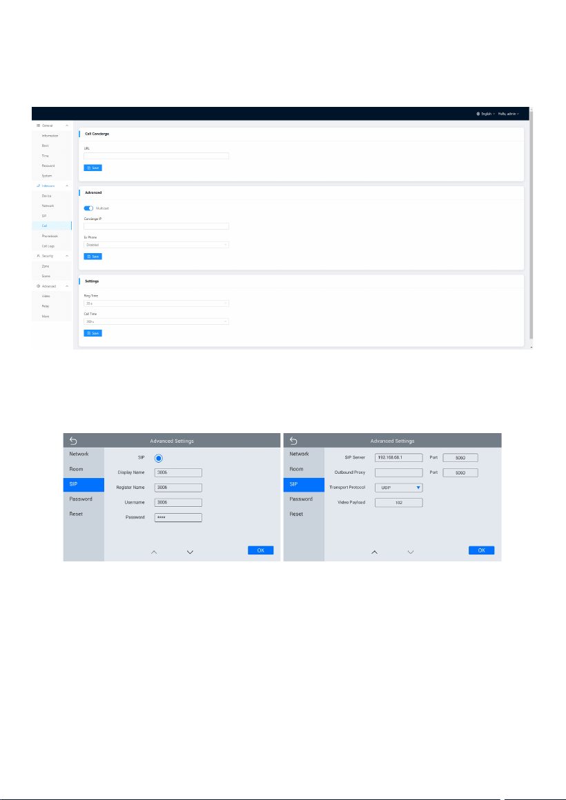
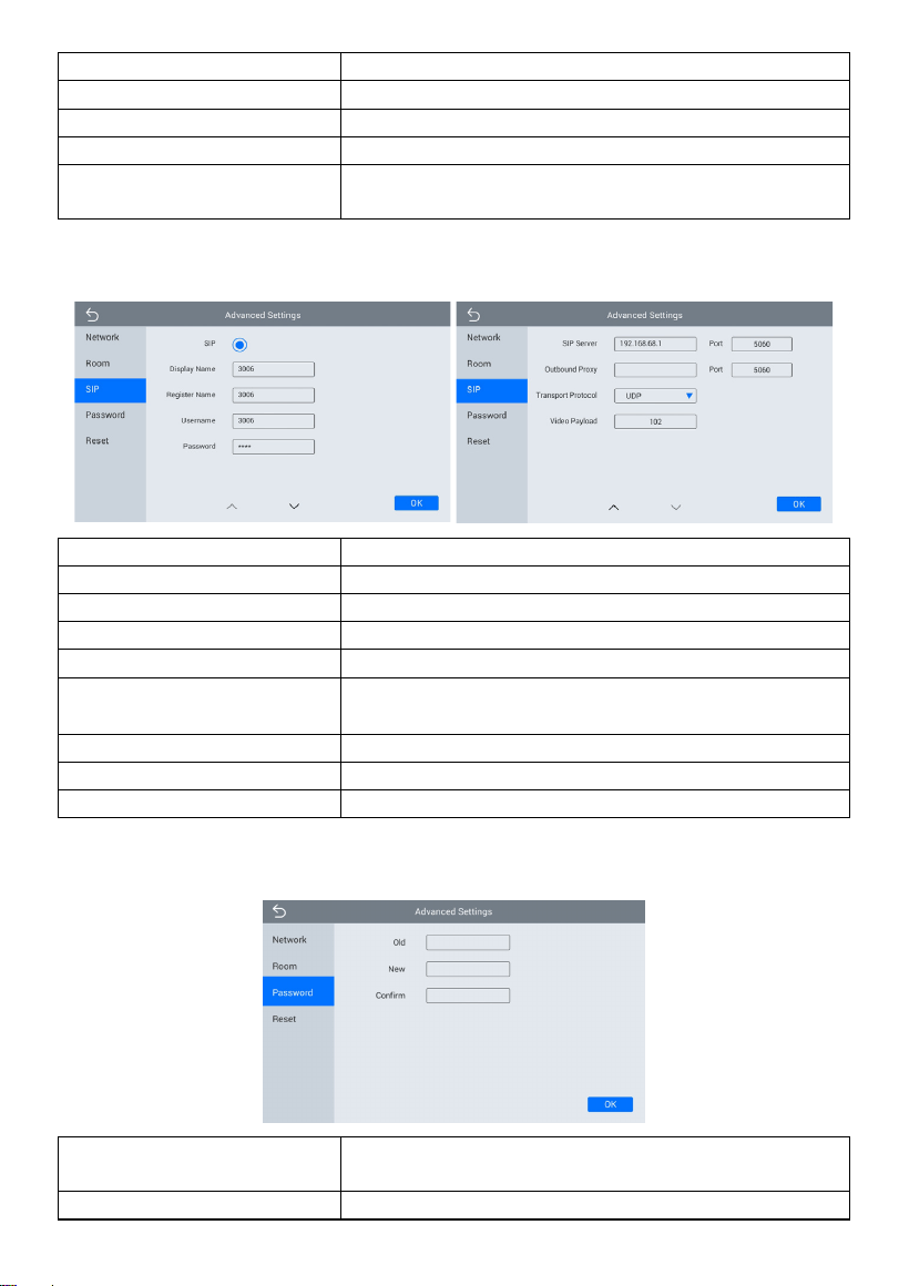
10. More > SIP
SIP:
Enable to use SIP;
Display Name:
Display name of SIP account;
Register Name:
Register Name of SIP account;
Username:
Username of SIP account;
Password:
Password of SIP account;
SIP Server Host:
Directly fill in SIP server’s address e.g., 192.168.68.90;
The default port is 5060;
Outbound Proxy:
Outbound Proxy server; the default port is 5060;
Transport Protocol:
Transport Protocol (UDP, TCP, TLS);
Video Payload:
Video payload range is 96-127;
11. More > Password
Old Password:
Current administrator password of the Device
(Default 123456);
New Password:
New administrator password of the Device;
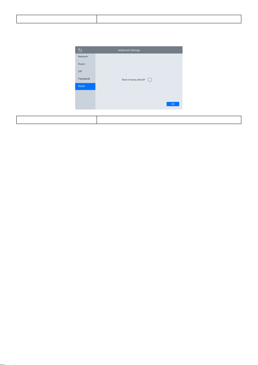
- 18 -
Confirm Password:
Confirm administrator password of the Device;
12. More > Reset
Reset:
Reset to factory default;
- 19 -
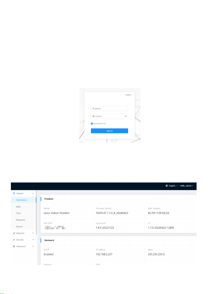
WEB SETTING
Connect Indoor Monitor and PC to a network switch in the same LAN. You can enter
the IP address of Indoor Monitor in the web browser search bar and log in with the
default account (admin) and password (123456). This is where you can configure the
device.
To get the IP address, you can search by Remote Upgrade Tool installed in the same
LAN with the devices.
1. General
1.1 General > Information
When you first log in to the web interface, you can find basic information displayed in
this dashboard.
- 20 -
Model:
Model of the device;
Firmware Version:
Firmware version of the device;
MAC Address:
MAC address of the device;
Framework:
Framework of the device;
UI:
UI of the device;
DHCP:
Status of DHCP;
IP Address:
Current IP address of the device;
Mask:
Subnet mask of the device;
Gateway:
Gateway of the device;
DNS:
Domain Name Server of the device;
Account:
SIP account of the device;
Status:
Status of SIP registration of the device;
CMS IP:
IP address of CMS;
Status:
Status of CMS registration;
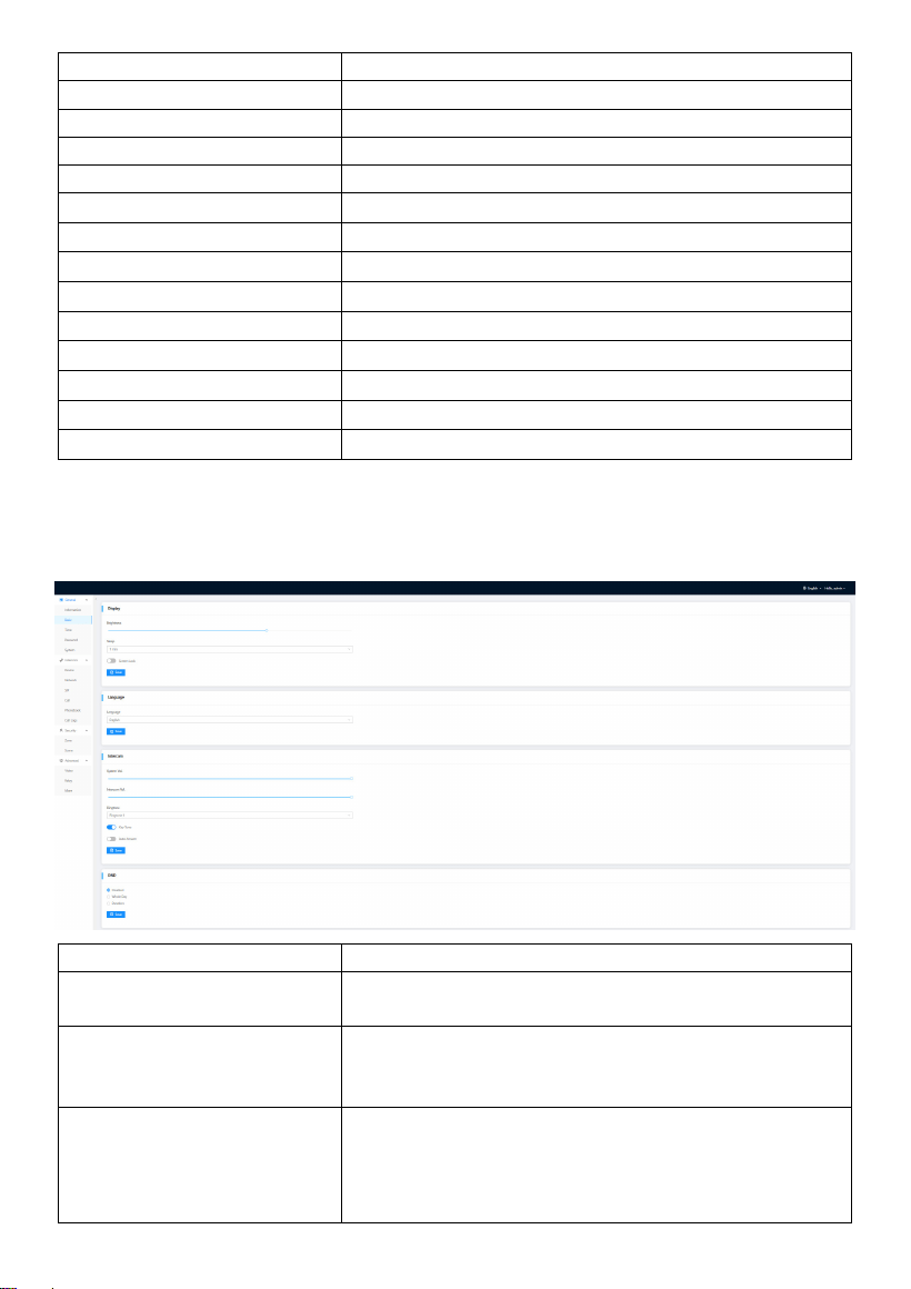
1.2 General > Basic
Some basic settings of the device can be configured in this column.
Brightness:
The brightness of the screen;
Sleep:
Screen off timeout (15s, 30s, 1min, 2mins, 5mins, 10
mins, 30mins);
Screen Lock:
The screen will be locked after screen off timeout (U
nlock password is security password. The default pa
ssword is 1234);
Language:
16 languages supported (简体中文, English, 繁體中
文, תי ִרב ִﬠ, Deutsch, Español, Türk, Tiếng Việt, Nederl
ands, Português, Polski, Русский, ﻲﺑرﻋ
, Français, Itali
ano, slovenský);
- 21 -
System Vol:
Volume of System can be set from 1 to 6. Volume 6 i
s the maximum volume (Key tone);
Intercom Vol:
Volume of Intercom can be set from 1 to 6. Volume
6 is the maximum volume (Call volume);
Ringtone:
The ringing sound (Ringtone 01-04);
Key Tone:
The keytone (Enable or disable);
Auto Answer:
Pick up the phone automatically when receiving a c
all;
DND:
DND is disabled by default.
Whole Day: when DND is enabled, it will reject calls
for the whole day.
Duration: when DND is enabled, it will reject calls du
ring this time.
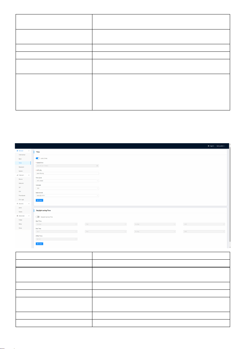
1.3 General > Time
Time of the device can be configured.
Daylight Saving Time is also supported.
Auto (Time):
Enable to synchronize computer time;
Date&Time:
Date and time can be set manually;
NTP URL:
Network Time Protocol (NTP) is a protocol used to sy
nchronize NTP time;
Time Zone:
A region that observes a uniform standard time;
12H/24H:
Select 12H or 24H format to display on the device;
Date Format:
3 time formats supported (YYYY-MM-DD, DD-MM-Y
YYY, MM-DD-YYYY);
Daylight-saving Time:
Enable to set DST;
Start Time:
The beginning of DST;
- 22 -
End Time:
The ending of DST;
Offset Time:
The default value is 60 minutes;
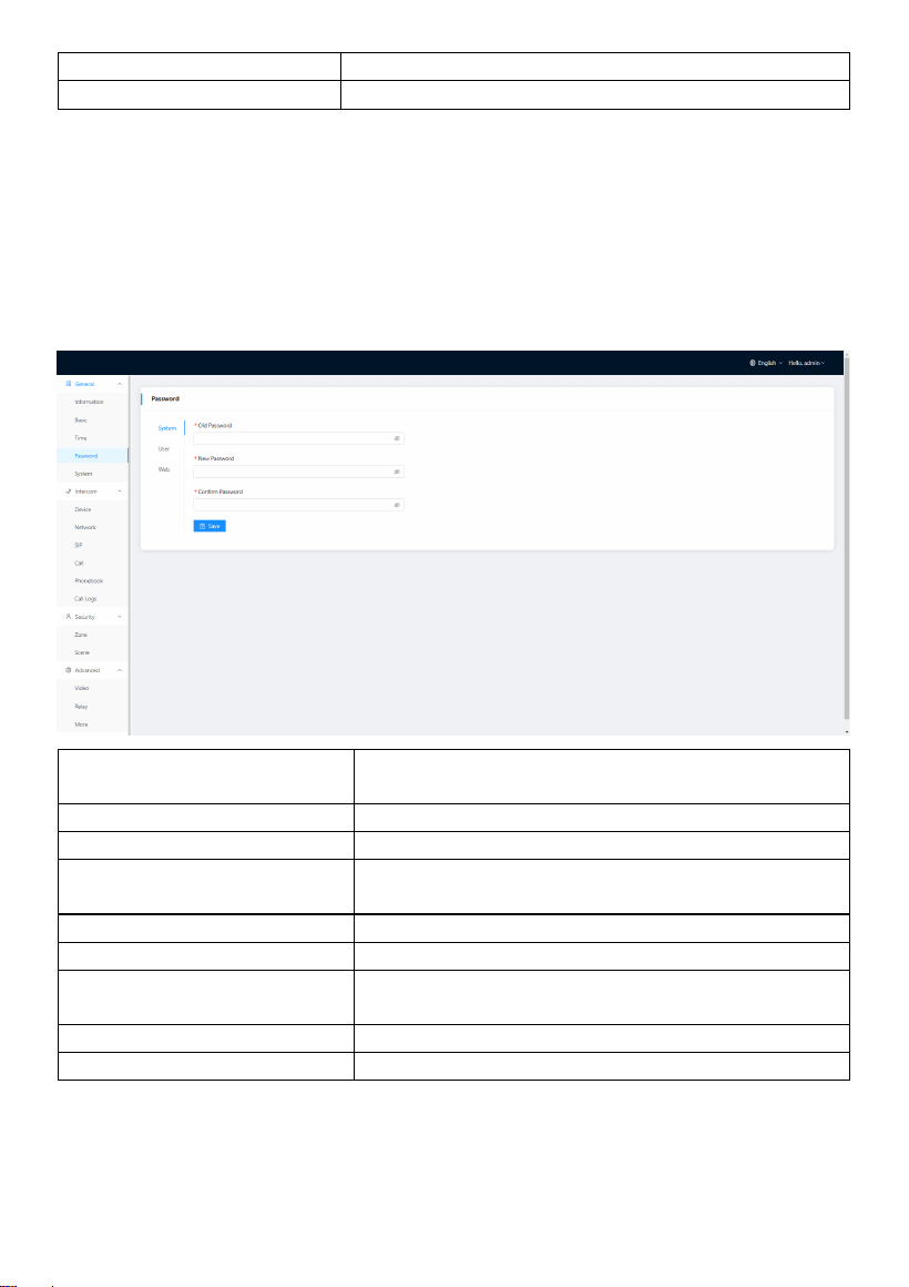
1.4 General > Password
The System password is for the administrator to log in settings on the device while the
Web password is for the administrator to log in settings on the web. The default
password for both of them is 123456. User for Indoor Monitor is the security password
whose default password is 1234.
System Old Password:
Current administrator password of the Device (Def
ault 123456);
System New Password:
New administrator password of the Device;
System Confirm Password:
Confirm administrator password of the Device;
User Old Password:
Current security password of the Device (Default 1
234);
User New Password:
New security password of the Device;
User Confirm Password:
Confirm security password of the Device;
Web Old Password:
Current administrator password of the web (Defaul
t 123456);
Web New Password:
New administrator password of the web;
Web Confirm Password:
Confirm administrator password of the web;
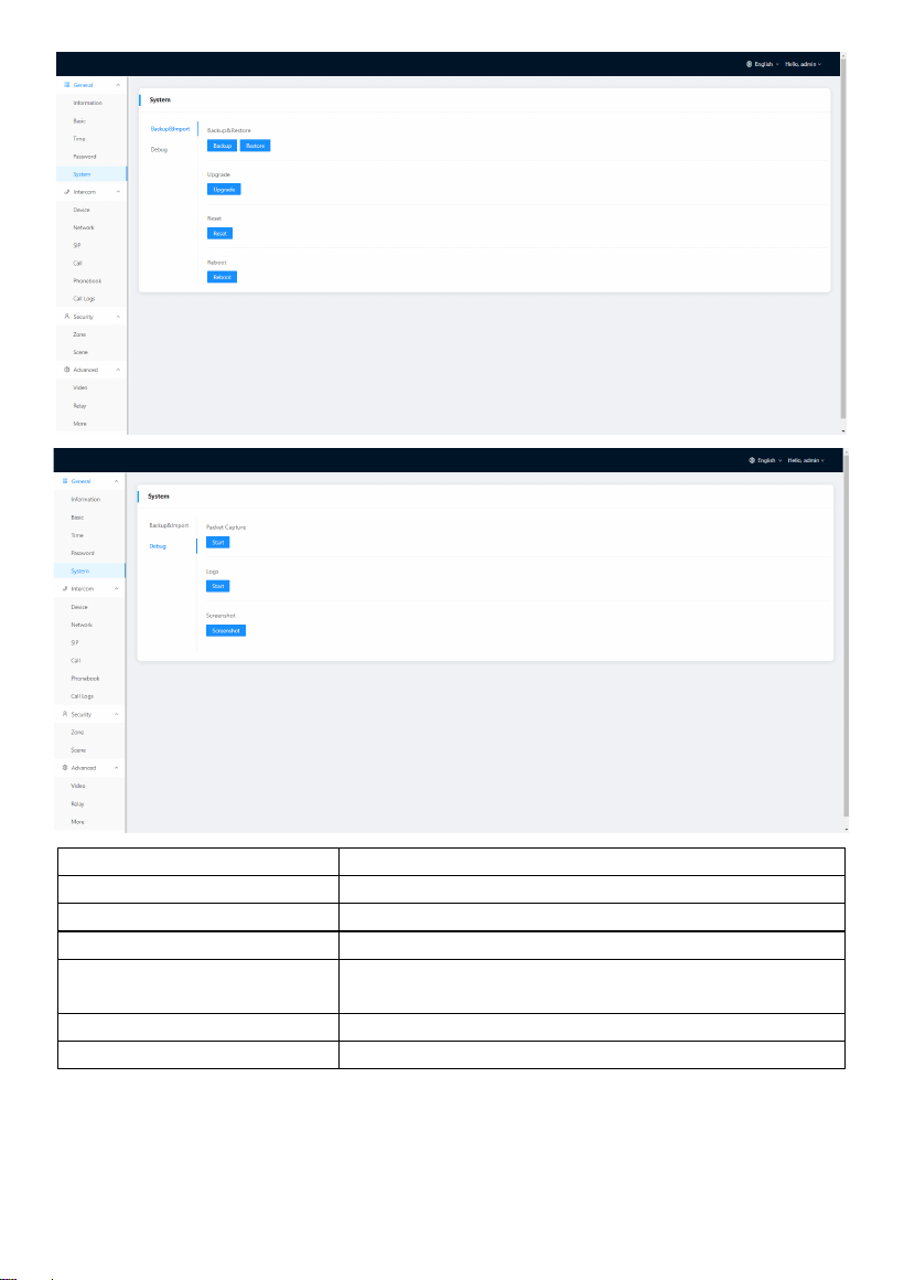
1.5 General > System
The system column is designed for data backup and restore, firmware upgrade, factory
default, device reboot, packet capture, logs capture, and obtaining UI screenshots.
- 23 -
Backup&Restore:
Backup all setting and restore settings;
Upgrade:
Upgrade equipment;
Reset:
Reset to factory settings;
Reboot:
Reboot the device;
Packet Capture:
Capturing packets can help developers reproduce p
ositioning problems;
Logs:
Device logs;
Screenshot:
Screenshot device interface;
- 24 -
2. Intercom
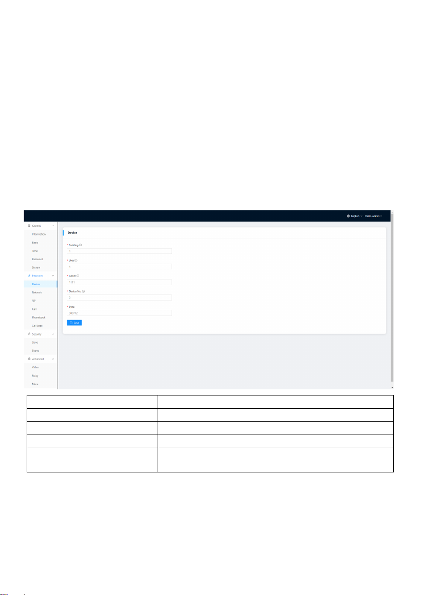
2.1 Intercom > Device
Numbers here are basic settings for making a call to Indoor Monitor. For Door Station,
the building and unit number should be the same as those in Indoor Monitor.
For Villa Station with one button, the building, unit, and room number should be the
same as those in Indoor Monitor.
When users want to use more than 1 Indoor Monitors, keep Building, Unit, Apartment
No., Sync the same as other Indoor Monitors, and Device number should be different.
The Device number can be from 0 to 9. But you must have one Indoor Monitor’s Device
number is 0 and keep it online because 0 here stands for the main one.
Building:
Number of the building (Range: 1-999);
Unit:
Number of the unit (Range: 0-99);
Room:
Number of the apartment (Range: 0-9899);
Device No:
Number of the device (Range: 0-9);
Sync:
A number used to synchronize to other Indoor Moni
tors;
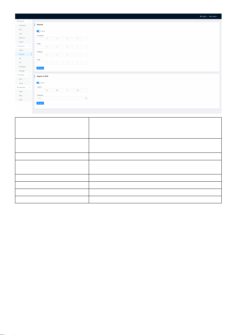
2.2 Intercom > Network
The device network can be set to either DHCP or a static IP address. CMS parameters
should be configured here when you try to register this device to CMS.
- 25 -
DHCP:
Enable DHCP (Dynamic Host Configuration Protoco
l) to dynamically distribute network configuration p
arameters;
IP Address:
Configure Static IP address to manually distribute ne
twork configuration parameters;
Mask:
Subnet mask;
Gateway:
A component that is part of two networks, which us
e different protocols;
DNS:
Domain Name Server of the device;
CMS:
Enable to use CMS software to manage devices;
CMS IP:
Server address of CMS;
Password:
Password you set for this device’s CMS registration;
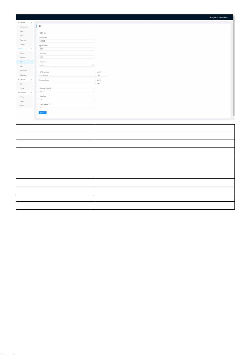
2.3 Intercom > SIP
The SIP column concerns SIP registration, Display Name, Register Name, Username,
Password, SIP Server Host, Outbound Proxy, Transport Protocol, Video Payload, etc.
- 26 -
SIP:
Enable to use SIP;
Display Name:
Display name of SIP account;
Register Name:
Register Name of SIP account;
Username:
Username of SIP account;
Password:
Password of SIP account;
SIP Server Host:
Directly fill in SIP server’s address e.g., 192.168.68.90;
The default port is 5060;
Outbound Proxy:
Outbound Proxy server; the default port is 5060;
Transport Protocol:
Transport Protocol (UDP, TCP, TLS);
Ring Code:
Ring code. Without SDP or with (180 or 183);
Video Payload:
Video payload range is 96-127;
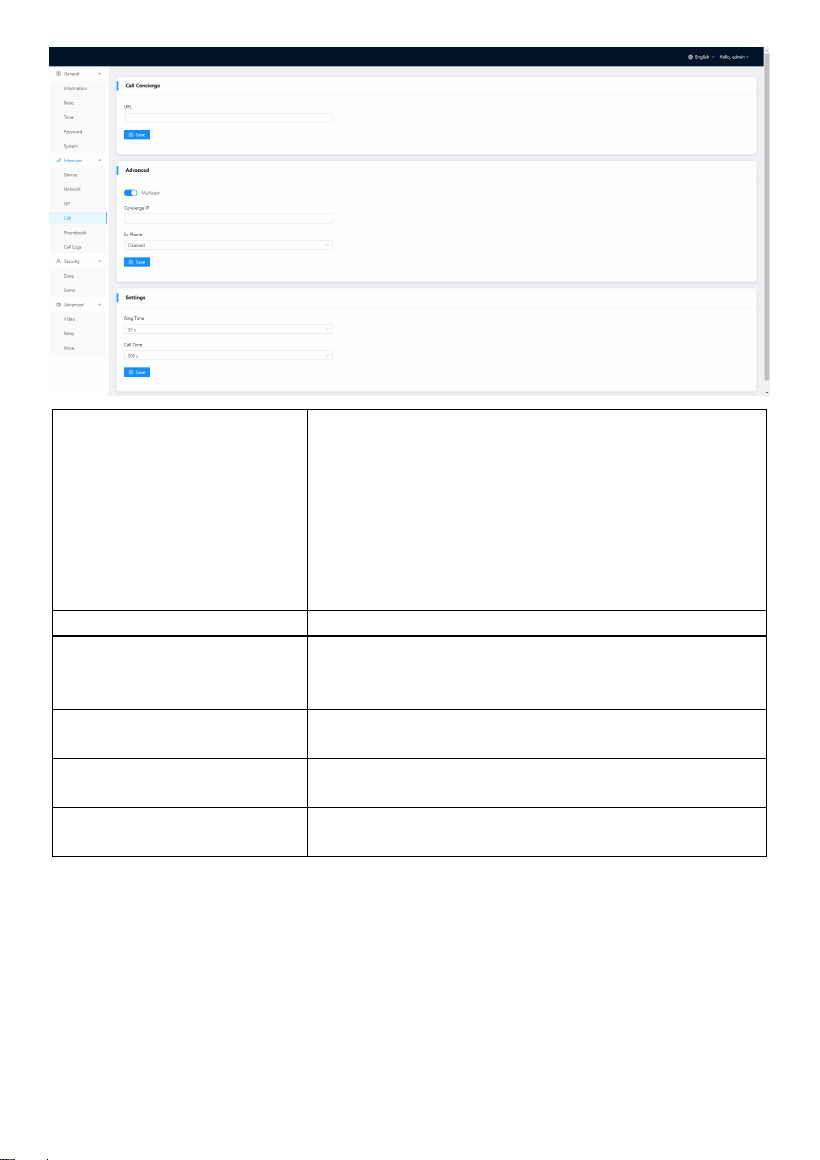
2.4 Intercom > Call
Ring group is for setting up SIP calls or call mode. Concierge button, extension of other
Indoor Monitors, the length of the call, and ring time can also be configured here.
- 27 -
Call Concierge URL:
Fill in the call destination for concierge button or
the single button on the device;
IP call:
Fill in sip:IP address,
e.g., sip:192.168.68.90;
SIP call:
Fill in sip:sip account@SIP server address:port, e.g., si
p:101@192.168.68.90:5060;
Multicast:
Enable to receive broadcast from Master Station;
Concierge IP:
Fill in the message receiver’s (Indoor Monitor or Mas
ter Station) IP address. The message edited on Indo
or Monitor will send to this destination;
Ex Phone:
Extend to more Indoor Monitors by filling in sip:IP a
ddress (6 Max) such as sip:192.168.68.90 (6 Max);
Ring Time:
The ring will be ended automatically after a period o
f time (10s, 20s, 35s, 45s, 60s, 90s, 120s)
Call Time:
The call will be ended automatically after a period of
time (120s, 300s, 600s, 1200s, 1800s);
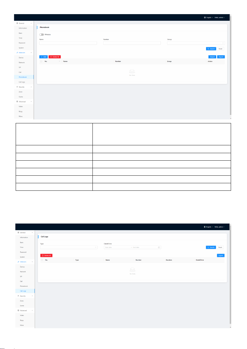
2.5 Intercom > Phonebook
All contacts on Indoor Monitor can be edited here.
- 28 -
Whitelist:
Enable whitelist to block other calls outside of the w
hitelist. For example, Ana is in the whitelist but Nyre
e isn’t in it. Ana can call in while Nyree can’t;
Search:
Fill in text inputs to search;
Reset:
Click reset to clear words in text inputs;
Add:
Click to add more contacts;
Delete All:
Delete all data on the chart;
Import:
Import all data to the chart;
Export:
Export all data on the chart;
2.6 Intercom > Call Logs
All call logs can be checked here.
- 29 -
Search:
Fill in text inputs to search;
Reset:
Click reset to clear words in text inputs;
Delete All:
Delete all data on the chart;
Export:
Export all data on the chart;
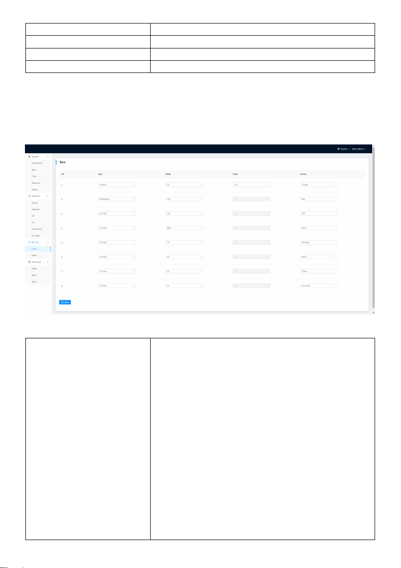
3. Security
3.1 Security > Zone
Zone column is the setup page for security sensors.
Type:
• Normal: When users enable an alarm scene on the
On/Off page, Normal type alarm zone will be
activated after activation time.
o 100 seconds is the default activation time, it
means the alarm will be activated after 100
seconds.
o After 100s, once sensor is triggered, Indoor
Monitor will send this alarm to Master Station.
o But sometimes users don't want to send the
alarm to Master Station (maybe alarm by
mistake), users can set the Delay time, so they
can cancel the alarm in the Indoor Monitor
during this Delay time (PIR, Door, Window);
• Emergency: once Panic button is triggered, Indoor
Monitor will not initiate an alarm and only Master
Station will receive alarms secretly; 24 hours
standby even if the security is off (Panic, Pull
- 30 -
Cord);
24 Hour: Indoor Monitor will initiate an alarm and M
aster Station will also receive alarms. 24 hours stand
by even if the security is off (Smoke, Gas, Flood);
Mode:
•
3C: for the sensor with 2.2KΩ resistance;
Regardless of the connection to NC or NO, the
alarm can be triggered normally;
• NO: normally open;
• NC: normally closed;
BELL: in BELL mode, Master Station will not receive a
ny alarm. Indoor Monitor is regarded as a doorbell r
eceiver;
Delay:
Once sensor is triggered, Indoor Monitor will send t
his alarm to Master Station, but users can terminate
the alarm sending to Master Station during the dela
yed time set here. Delay setting is only effective for
Normal type (0s, 5s, 15s, 20s, 25s, 40s, 60s);
Sensor:
Sensor types (Smoke, Gas, PIR, Door, Window, Panic,
Flood, Pull Cord);
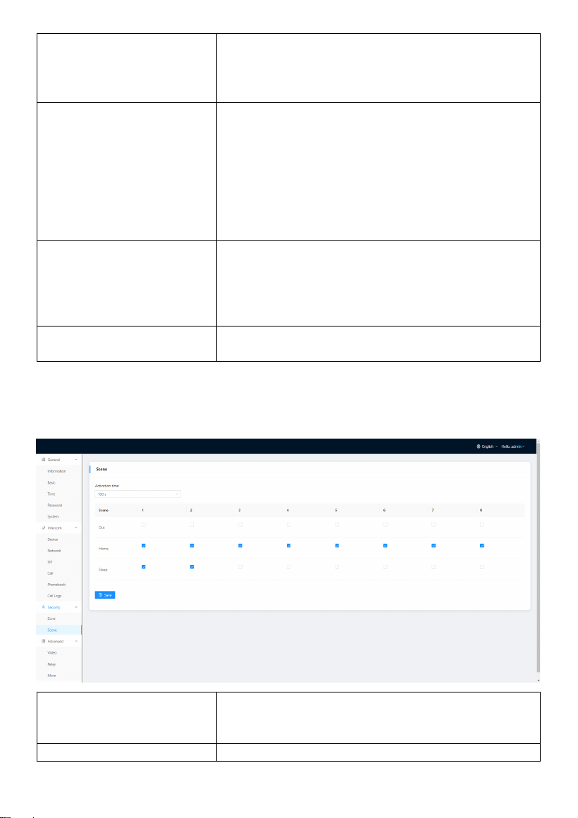
3.2 Security > Scene
Scene column is for security sensors’ trigger conditions.
Activation Time:
Only after activation time, will scene be activated. A
ctivation time is only effective for Normal type (NON
E, 30s, 40s, 60s, 100s, and 300s);
Mode:
Tick to link sensors to Out, Home, or Sleep scene;
- 31 -
4. Advanced
4.1 Advanced > Video
Video here is for users to show their IPC image for the one they are talking with. For
example, users receive calls from Master Station or Indoor Monitor. They can see the
IPC image because users filled in IPC’s RTSP Feed here.
RTSP Feed:
Fill in the IP camera stream URL here.
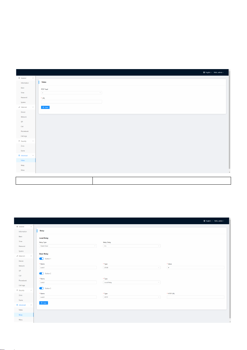
4.2 Advanced > Relay
Relay column is for Local Relay and Door Relay.
- 32 -
Local Relay Type:
Type of local relay (Open Door is for lock/Chime Bell
is for doorbell);
Local Relay Delay:
The length of unlock delay time (1-9s);
Unlock Button 1-3:
Enable or disable relays for unlock buttons;
Name:
Customize name for unlock button;
Type:
Type 1-3: 3 types of unlock way are optional (Local
Relay/DTMF/HTTP)
HTTP——the format is http://192.168.3.119/cgi-
bin/webapi.cgi?api=unlock&index
=2&username=admin&password
=E10ADC3949BA59ABBE56E057F20F883E;
Note:
• "192.168.3.119" is the IP address of Door Station;
• The number "2" after "index=" is the number for relay. (Relay 1 is 0; relay 2 is
1; relay 3 is 2);
• "admin" here should be changed to your admin account;
• "Password" is Password of admin;
• "E10ADC3949BA59ABBE56E057F20F883E" here is MD5 (Message-Digest
Algorithm) encrypted. Users need to use account password to encrypt and
change it.
DTMF——Dual-tone multi-frequency signaling,
Relay1: #, Relay2:0, relay3: *;
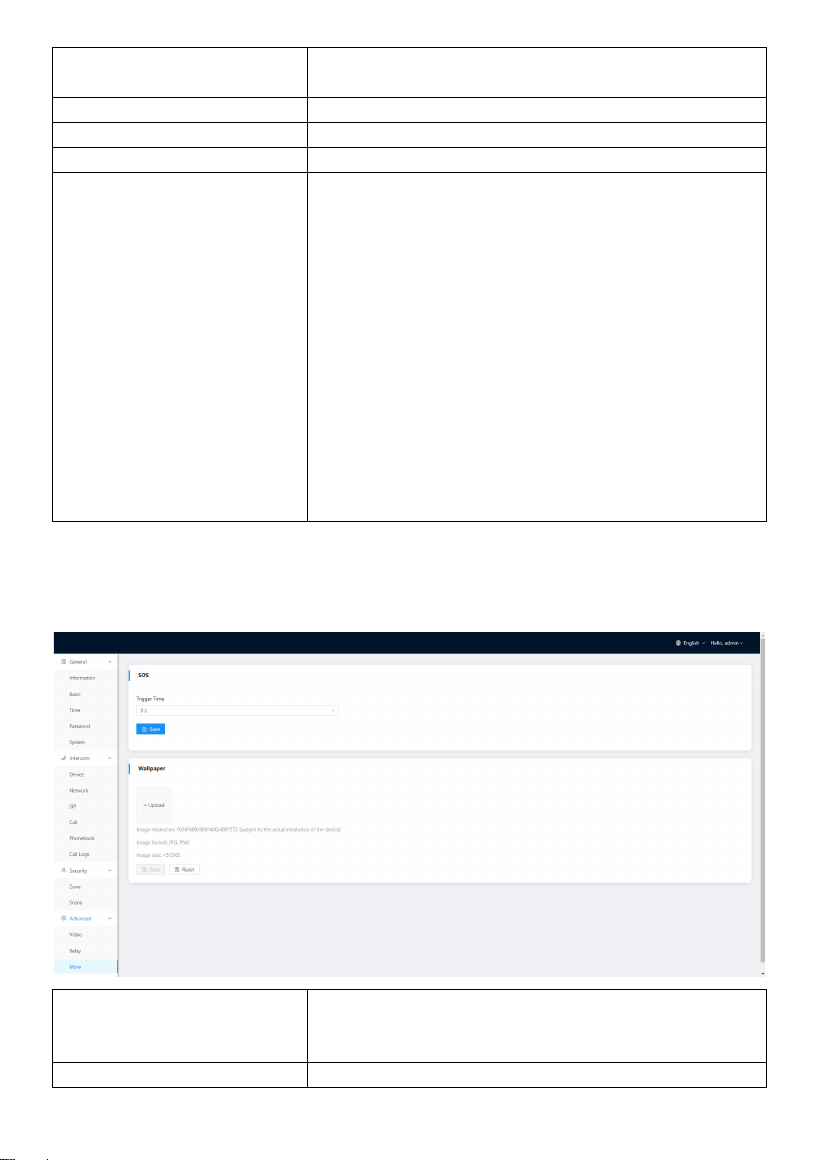
4.3 Advanced > More
More column is for SOS and Wallpaper.
SOS:
Trigger Time can be set to 0s and 3s. If the time is
set to 3s, users need to press the SOS icon for 3s to
send out SOS in case of a wrong operation alarm.;
Wallpaper:
Upload a picture to apply it to the device UI. Please
- 33 -
make sure the picture’s resolution is the same as the
device’s and the size of the picture should be lower
than 512KB. The format of Picture should be JPG or
PNG;
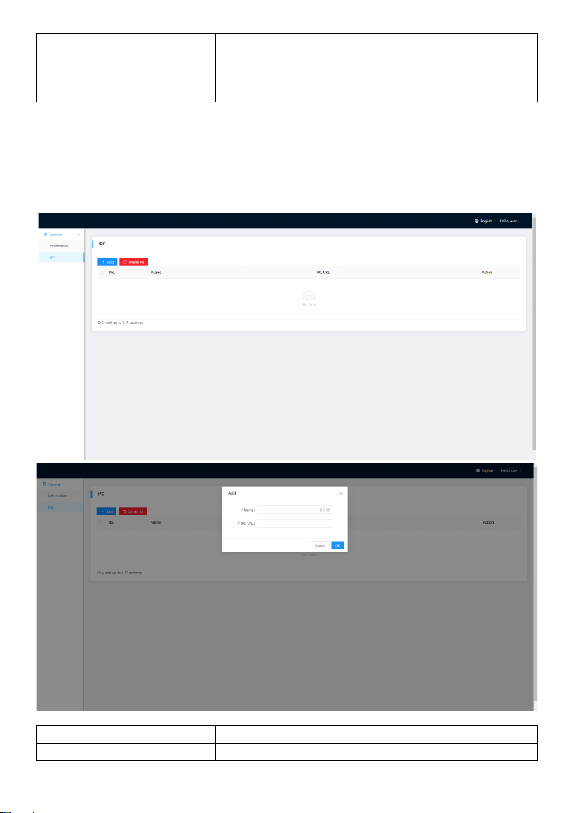
5. General
You can enter the IP address of Indoor Monitor in the web browser search bar and log
in with the default account (user) and password (1234). This is where you can add IPC.
Name:
Customize name of IPC;
IPC URL:
Fill in IPC’s RTSP stream;
- 34 -
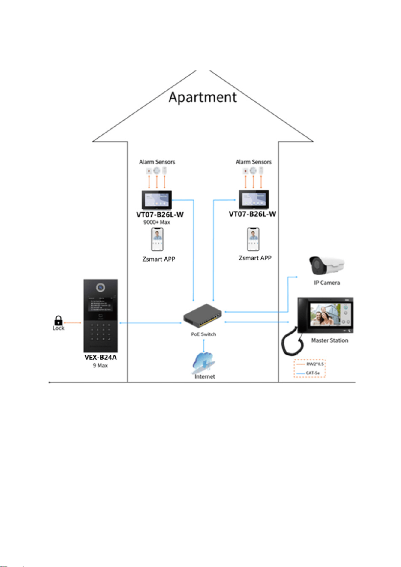
SYSTEM DIAGRAM
- 35 -
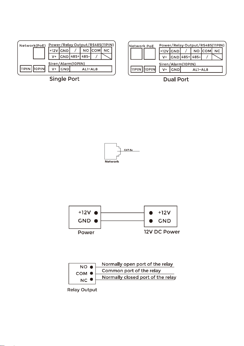
DEVICE WIRING
1. Network (PoE)
Standard RJ45 interface is used to be connected to the Master Station, Indoor Monitor
and/or other network equipment.
PSE shall comply with IEEE 802.3af (PoE) and its output power not less than 15.4W and
its output voltage not be less than 50V.
2. Power
The power interface of Indoor Monitor connects to 12V DC power.
3. Relay Output
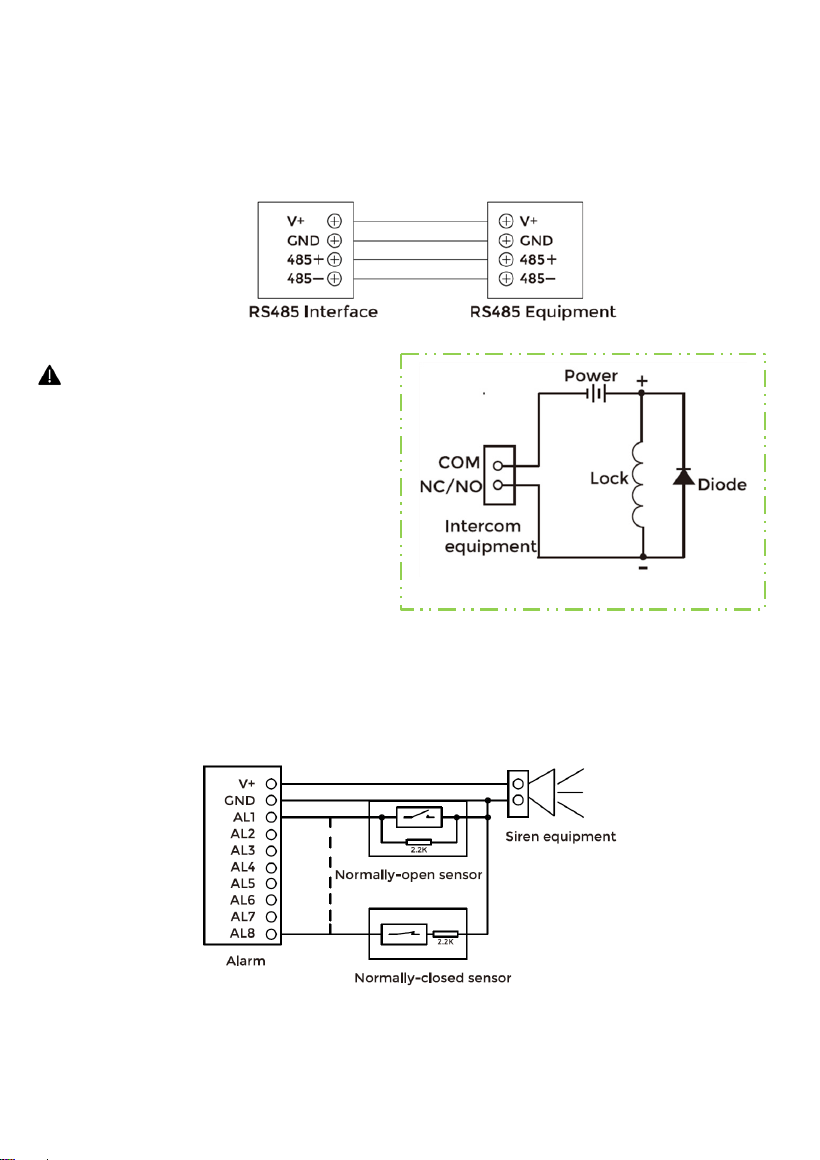
- 36 -
4. RS485
Enable to connect equipment with RS485 interface. RS485 interface can output
12V/100mA power supply. If RS485 equipment to be connected doesn't require the
power supply, there is no need to connect to +12V.
5. Siren/Alarm
Interface of alarm zones connects with normally-open or normally-closed switch. When
the alarm zone is triggered, it will output 12V/100mA power.
Warning!
1. When connecting to an inductive load device such as a relay
or electromagnetic lock, you are recommended to use a diode
1A/400V (included in the accessories) in anti-parallel with the
load device to absorb inductive load voltage peaks. The
intercom will be better protected in this way.
2. The load current of the relay cannot be greater than 2A. See
attached picture for more details.
- 37 -
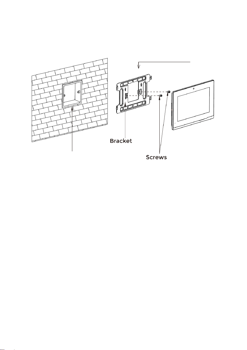
INSTALLATION
Surface Mounting-Asian Gang Box
Product size:
195 × 130 × 14.5 mm
Asian Gang Box
- 38 -
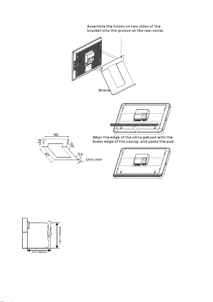
Desktop Mounting
Product size:
195 × 130 × 14.5 mm
Tips:
The camera should be 1450~1550mm above the ground. The
camera at this height can capture human face perfectly.

- 39 -
TROUBLESHOOTING
The Indoor Monitor cannot start up or power off automatically.
Check whether it has power-failure, and power it on again
The Indoor Monitor display screen is too dim.
Check whether the brightness and contrast settings of screen are correct.
No sound during the communication.
Check whether the Indoor Monitor is set as mute mode, or the volume is set to the
lowest.
The Indoor Monitor cannot monitor the Door Station.
Other user is using the system, so you can use it once he/she finished the operation.
Multimedia files cannot be played normally.
Check whether the system supports the file format. Please refer to the multimedia
setting for details.
No response when clicking Indoor Monitor display screen.
Press "Unlock" button for 5s, or slowly slide horizontally or vertically on the LCD to
make touchscreen calibration. It needs to be calibrated.
Touchscreen responses slowly or cannot make calibration.
Take down any protective paster, since it may affect identification
and input for device;
Ensure the finger is dry and clean when clicking touchscreen;
Restart the device to clear any temporary software error.
The temperature of device is too high.
Long-term use leads to high temperature. It’s normal and will not affect the
device’s use life and performance.

- 40 -
SAFETY INSTRUCTION
In order to protect you and others from harm or your device from damage, please read the
following information before using the device.
Do not install the device in the following places:
Do not install the device in high-temperature and moist environment or the area close to
magnetic field, such as the electric generator, transformer or magnet.
Do not place the device near the heating products such as electric heater or the fluid
container.
Do not place the device in the sun or near the heat source, which might cause discoloration
or deformation of the device.
Do not install the device in an unstable position to avoid the property losses or personal
injury caused by the falling of device.
Guard against electric shock, fire and explosion:
Do not use damaged power cord, plug or loose outlet.
Do not touch the power cord with wet hand or unplug the power cord by pulling.
Do not bend or damage the power cord.
Do not touch the device with wet hand.
Do not make the power supply slip or cause the impact.
Do not use the power supply without the manufacturer's approval.
Do not have the liquids such as water go into the device.
Clean Device Surface
Clean the device surfaces with soft cloth dipped in some water, and then rub the surface with
dry cloth.
Other Tips
In order to prevent damage to the paint layer or the case, please do not expose the device to
chemical products, such as the diluent, gasoline, alcohol, insect-resist agents, opacifying
agent and insecticide.
Do not knock on the device with hard objects.
Do not press the screen surface. Overexertion might cause flopover or damage to the device.
Please be careful when standing up from the area under the device.
Do not disassemble, repair or modify the device at your own discretion.
The arbitrary modification is not covered under warranty. When any repair required, please
contact the customer service center.
If there is abnormal sound, smell or fume in the device, please unplug the power cord
immediately and contact the customer service center.
When the device isn’t used for a long time, the adaptor and memory card can be removed
and placed in dry environment.
When moving, please hand over the manual to new tenant for proper usage of the device.

ZKTeco Industrial Park, No. 32, Industrial Road,
Tangxia Town, Dongguan, China.
Phone : +86 769 - 82109991
Fax : +86 755 - 89602394
www.zkteco.com
Copyright © 2024 ZKTECO CO., LTD. All Rights Reserved.


