
DAMAIS36SSV2
Installation Instructions
Use and Care Information
Instructions d'installation
Utilisez et d'entretien
Instrucciones de instalación
Información de uso y cuidado
DAMA ISOLA

2
READ AND SAVE THESE INSTRUCTIONS BEFORE YOU START
INSTALLING THIS RANGEHOOD
WARNING: - TO REDUCE THE RISK OF A RANGE TOP GREASE FIRE:
a) Never leave surface units unattended at high settings. Boilovers cause smoking and
greasy spillovers that may ignite. Heat oils slowly on low or medium setting.
b)AlwaysturnhoodONwhencookingathighheatorwhenambeingfood(i.e.Crepes
Suzette,CherriesJubilee,PeppercornBeefFlambé).
c)Cleanventilatingfansfrequently.Greaseshouldnotbeallowedtoaccumulateonfan
orlter.
d) Use proper pan size. Always use cookware appropriate for the size of the surface
element.
WARNING:-TOREDUCETHERISKOFINJURYTOPERSONSINTHEEVENTOFARANGE
TOPGREASEFIRE,OBSERVETHEFOLLOWING*:
a)SMOTHERFLAMESwithaclose-ttinglid,cookiesheet,ormetaltray,thenturnoffthe
burner.BECAREFULTOPREVENTBURNS.Iftheamesdonotgooutimmediately
EVACUATEANDCALLTHEFIREDEPARTMENT.
b)NEVERPICKUPAFLAMINGPAN-Youmaybeburned.
c)DONOTUSEWATER,includingwetdishclothsortowels-aviolentsteamexplosion
will result.
d)UseanextinguisherONLYif:
1. YouknowyouhaveaClassABCextinguisher,andyoualreadyknowhowtooperate
it.
2. Thereissmallandcontainedintheareawhereitstarted.
3. Theredepartmentisbeingcalled.
4. Youcanghttherewithyourbacktoanexit.
*Basedon"KitchenFiresafetyTips"publishedbyNFPA
WARNING-TOREDUCETHERISKOFFIREORELECTRICSHOCK,donotusethisfan
withanysolid-statespeedcontroldevice.
WARNING-TOREDUCETHERISKOFFIRE,ELECTRICALSHOCK,ORINJURYTOPER-
SONS,OBSERVETHEFOLLOWING:
1. Usethisunitonlyinthemannerintendedbythemanufacturer.Ifyouhaveanyque-
stions, contact the manufacturer.
2. Before servicing or cleaning unit, switch power off at service panel and lock the
service disconnecting means to prevent power from being switched on accidentally.
When the service disconnecting means cannot be locked, securely fasten a prominent
warning device, such as a tag, to the service panel.
CAUTION: For General Ventilating Use Only. Do Not Use To Exhaust Hazardous or
ExplosiveMaterialsandVapors.
WARNING-TOREDUCETHERISKOFFIRE,ELECTRICALSHOCK,ORINJURYTOPER-
SONS,OBSERVETHEFOLLOWING:
1. InstallationWorkAndElectricalWiringMustBeDoneByQualiedPerson(s)InAccor-
danceWithAllApplicableCodesAndStandards,IncludingFire-RatedConstruction.
2. Sufcientairisneededforpropercombustionandexhaustingofgasesthroughthe
ue(chimney)offuelburningequipmenttopreventbackdrafting.Followtheheating
equipmentmanufacturer'sguidelineandsafetystandardssuchasthosepublished

3
bytheNationalFireProtectionAssociation(NFPA),andtheAmericanSocietyfor
Heating,RefrigerationandAirConditioningEngineers(ASHRAE),andthelocalcode
authorities.
3. When cutting or drilling into wall or ceiling, do not damage electrical wiring and
other hidden utilities.
4. Ductedfansusedtoexhaustcontaminantsmustalwaysbeventedtotheoutdoors.
ALL WALL AND FLOOR OPENINGS WHERE THE RANGEHOOD IS INSTALLED
MUST BE SEALED.
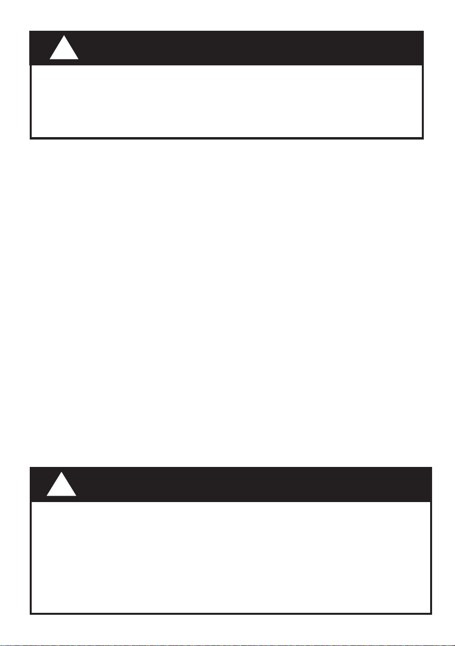
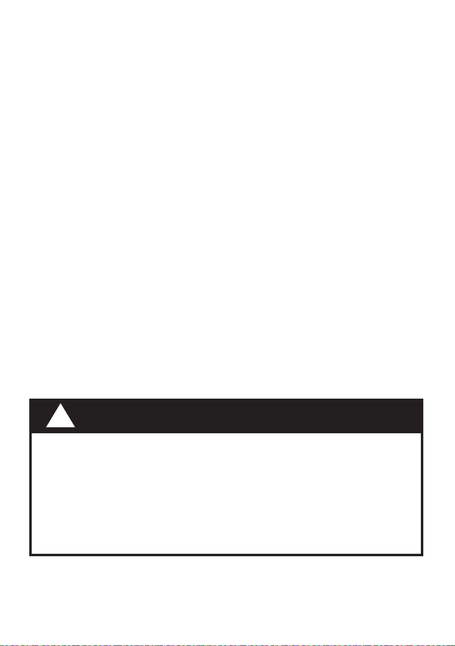
Thisrangehoodrequiresatleast24"ofclearance between the bottom of the rangehood
and the cooking surface or countertop. This hood has been approved by UL at this distance
from the cooktop.
This minimum clearance may be higher depending on local building codes. For gas cooktops
and combination ranges, a minimum of 30" is recommended and may be required.
Overhead cabinets on both sides of this unit must be a minimum of 18" above the cooking
surface or countertop. Consult the cooktop or range installation instructions given by the
manufacturer before making any cutouts.
MOBILE HOME INSTALLATION The installation of this rangehood must conform to the
Manufactured Home Construction and Safety Standards, Title 24 CFR, Part 3280 (formerly
Federal Standard for Mobile Home Construction and Safety, Title 24, HUD, Part 280). See
Electrical Requirements.
VENTINGREQUIREMENTS
Determine which venting method is best for your application. Ductwork can extend either
through the wall or the roof.
The length of the ductwork and the number of elbows should be kept to a minimum to
provide efcient performance. The size of the ductwork should be uniform. Do not install
two elbows together. Use duct tape to seal all joints in the ductwork system. Use caulking
to seal exterior wall or oor opening around the cap.
Flexibleductworkisnotrecommended.Flexibleductworkcreatesbackpressureand
air turbulence that greatly reduces performance.
Make sure there is proper clearance within the wall or oor for exhaust duct before making
cutouts. Do not cut a joist or stud u nless absolutely necessary. If a joist or stud must be
cut, then a supporting frame must be constructed.
WARNING-ToReduceTheRiskOfFire,UseOnlyMetalDuctwork.
CAUTION-Toreduceriskofreandtoproperlyexhaustair,besuretoductairout-
side–Donotventexhaustairintospaceswithinwallsorceilingsorintoattics,crawl
spaces, or garages.
WARNING:ToReduceTheRiskOfFire,ElectricShockOrInjuryToPersons,DoNot
UseReplacementPartsThatHaveNotBeenRecommendedByTheManufacturer(e.g.
PartsMadeAtHomeUsingA3DPrinter).
4
ELECTRICAL REQUIREMENTS
A 120 volt, 60 Hz AC-only electrical supply is required on a separate 15 amp fused circuit.
A time-delay fuse or circuit breaker is recommended. The fuse must be sized per local
codes in accordance with the electrical rating of this unit as specified on the serial/rating
plate located inside the unit near the field wiring compartment.
ELECTRICAL INSTALLATION WITH WIRING BOX
THIS UNIT MUST BE CONNECTED WITH COPPER WIRE ONLY. Wire sizes must conform
to the requirements of the National Electrical Code, ANSI/NFPA 70 - latest edition, and
all local codes and ordinances. Wire size and connections must conform with the rating
of the appliance. Copies of the standard listed above may be obtained from:
National Fire Protection Association
Batterymarch Park
Quincy, Massachusetts 02269
This appliance should be connected directly to the fused disconnect (or circuit bre-
aker) through flexible, armored or nonmetallic sheathed copper cable. Allow some
slack in the cable so the appliance can be moved if servicing is ever necessary. A
UL Listed, 1/2" conduit connector must be provided at each end of the power supply
cable (at the appliance and at the junction box).
When making the electrical connection, cut a 1 1/4" hole in the wall. A hole cut through
wood must be sanded until smooth. A hole through metal must have a grommet.
• Electrical ground is required on this rangehood.
• If cold water pipe is interrupted by plastic, nonmetallic gaskets or other materials,
DO NOT use for grounding.
• DO NOT ground to a gas pipe.
• DO NOT have a fuse in the neutral or grounding circuit. A fuse in the neutral or
grounding circuit could result in electrical shock.
• Check with a qualied electrician if you are in doubt as to whether the rangehood
is properly grounded.
• Failure to follow electrical requirements may result in a re.
WARNING
!
• Venting system MUST terminate outside the home.
• DONOT terminate the ductwork in an attic or other enclosed space.
• DONOT use 4" laundry-type wall caps.
• Flexible-type ductwork is not recommended.
• DONOT obstruct the ow of combustion and ventilation air.
• Failure to follow venting requirements may result in a re.
WARNING
!

5
CAUTION:Accessiblepartsmaybecomehotwhenusedwithcookingappliances.
• Theairmustnotbedischargedintoauethatisusedforexhaustingfumesfrom
appliances burning gas or other fuels
• lfaSTATIONARYAPPLIANCEisnotttedwithaSUPPLYCORDandaplug,or
with other means for disconnection from the supply mains having a contact se-
paration in all poles that previde full disconnection under overvoltage category
lII conditions, the instructions shall state that means for disconnection must be
incorporatedinthexedwiringinaccordancewiththewiringrules.
• Thedisconnectionmaybeachievedbyhavingtheplugaccessibleorbyincorpo-
ratingaswitchinthexedwiringinaccordancewiththewiringrules.
• Thisdeviceisnotintendedforusebypersons(includingchildren)whosephysical,
sensoryormentalabilitiesaredifferentorreduced,orwholackexperienceor
knowledge unless such persons receive supervision or training for the operation
of the device by a person responsible for their safety.
• Childrenshouldbesupervisedtoensuretheydonotusethedevicesasatoy.
• Donotamefoodundertherangehood.
• theairmustnotbedischargedintoauethatisusedforexhaustingfumesfrom
appliancesburninggasorotherfuels(notapplicabletoappliancesthatonlydi-
scharge the air back into the room);
• thereshallbeadequateventilationoftheroomwhentherangehoodisusedatthe
sametimeasappliancesburninggasorotherfuels(notapplicabletoappliances
that only discharge the air back into the room);
• thereisareriskifcleaningisnotcarriedoutinaccordancewiththeinstructions;
• Thisappliancemustbegrounded.Intheeventofanelectricalshortcircuit,groun-
ding reduces the risk of electric shock by providing an escape wire for the electric
current.Thisapplianceisequippedwithacordhavingagroundingwirewitha
groundingplug.Theplugmustbepluggedintoanoutletthatisproperlyinstalled
and grounded.
WARNING-lmpropergroundingcanresultinariskofelectricshock.
• Consultaqualiedelectricianifthegroundinginstructionsarenotcompletely
understood,orifdoubtexistsastowhethertheapplianceisproperlygrounded.
6
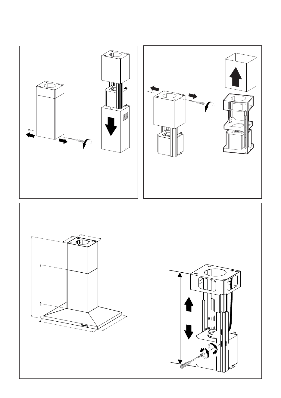
RANGEHOOD DIMENSIONS
Min. 24" Min. 30"
0,10$;
0,10$;

7
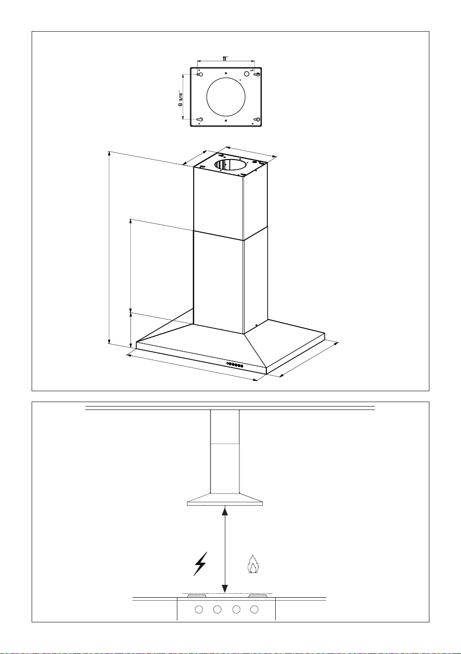
MAIN PARTS
Available Accessories
- High Ceiling Kit that replaces the upper flue. - sku#HIGH2.
- Ductless Kit - Includes Ductless Diverter, Charcoal Filters, Lower chimney with
vent grates - sku# DUCT2
- Activated Charcoal Filter Accessory - sku# FILTER2
- Wireless Remote Control Accessory - REMORIG
Parts needed
- 6" Round Metal ductwork
Components
Ref. Qty. Product Components
1 1 Hood Body, complete with: Con-
trols, Light, Filters, Blower.
2 1 Telescopic Chimney comprising:
2.1 1 Upper Section
2.2 1 Lower Section
7.1 1 Telescopic frame complete with
extractor, consisting of:
7.1a 1 Upper frame
7.1b 1 Lower frame
10 2 Flaps
11 1 Plasticxingcable
Ref. Qty. Installation Components
12q 4 Screws 1/8" x 1/4"
21 1 Drilling template
Qty. Documentation
1 Instruction Manual
10
1
2.2
2.1
21
7.1
12q
7.1a
7.1b
11
8
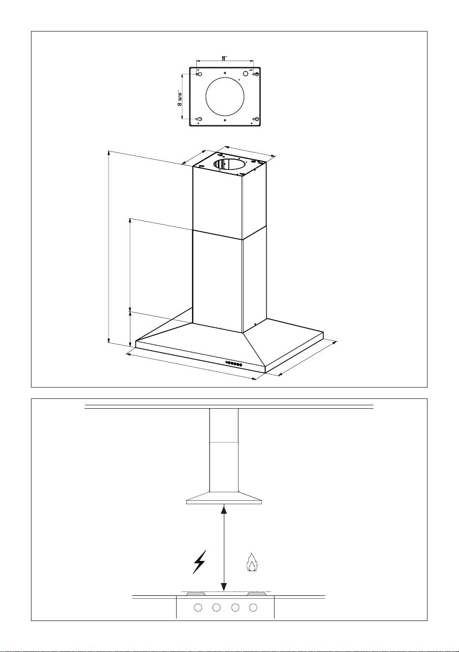
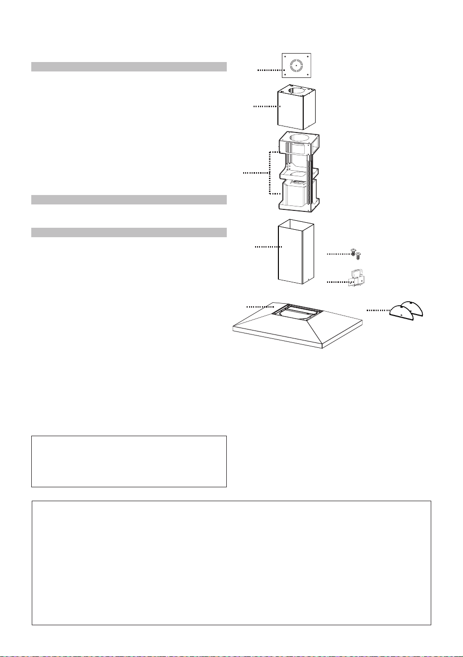
Choose your ducting method
Non Ducted - RecirculationDucted Venting Installation
Requires Ductless Accessory
Kit (purchased separately)
6 "
9
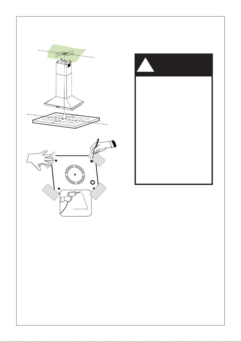
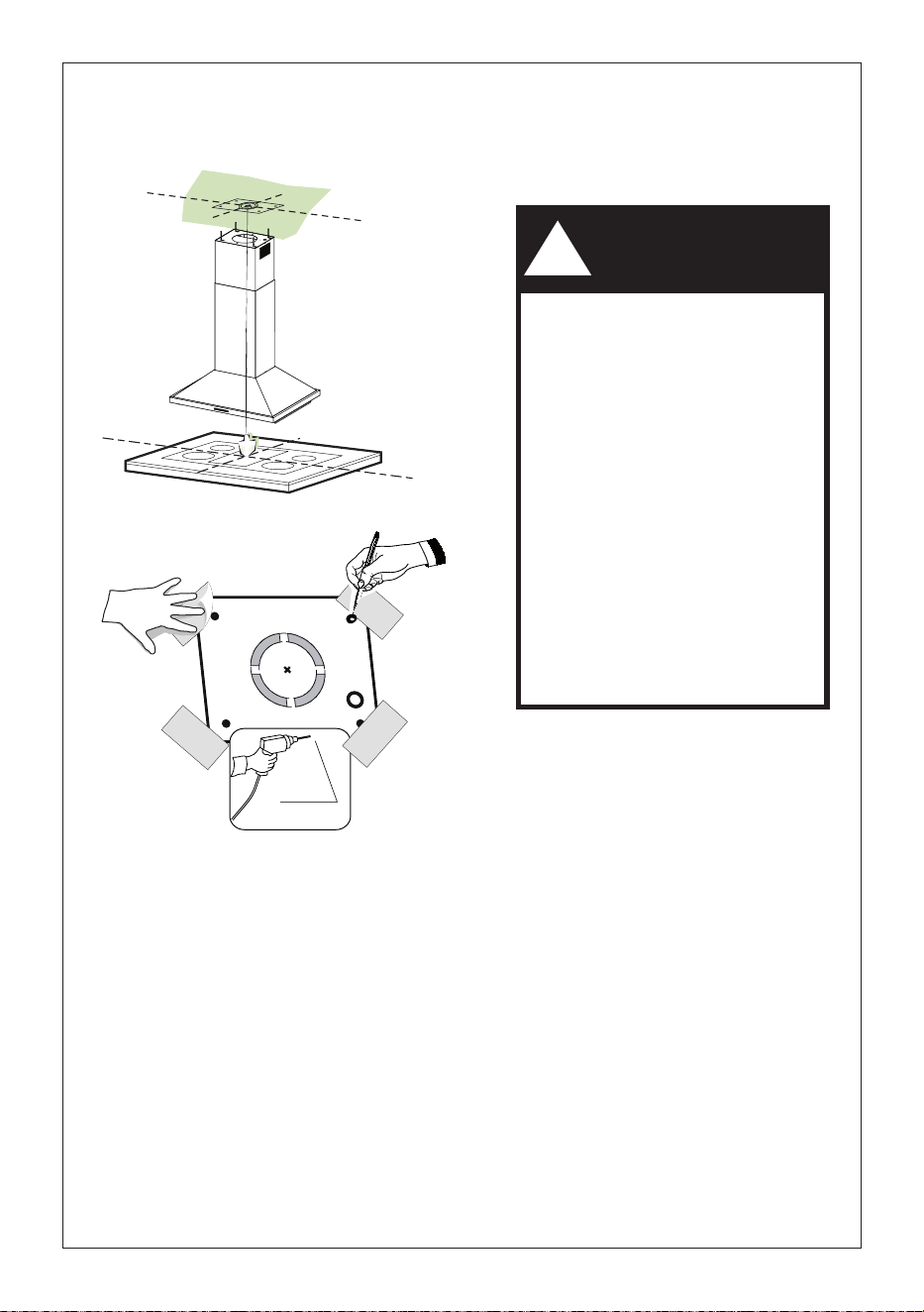
1
Put a thick, protective covering over
cooktop,
set-in range or countertop to protect from
damage or dirt.
Determine and clearly mark with a pencil
on the ceiling where the rangehood will
be installed.
A template 21 for mounting the support
is supplied in the carton with the support.
Use this template to mark holes for
support on the ceiling.
Determine and make necessary cuts for
the ductwork. The duct opening is shown
on the mounting template. Install
ductwork before mounting the hood.
Determine the proper location for the Power
Supply Cable as indicated on the template.
Use a 1 1/4" Drill Bit to make this hole. Run
the Power Supply Cable. Use caulking to
seal around the hole.
A knockout for threading through the
Power Supply from the ceiling is located on
the top of the frame. Do not connect the
Power Cable to the Wiring Box or power up
the hood at this time. Run enough power
cable from the ceiling to reach the wiring
box on the hood.
Ø 10 mm
x4
21
1 1/4"
Do not make any cutouts until you have decided whether this installation will be
ducted or non-duct and then plan accordingly.
DUE TO THE SIZE AND
WEIGHT OF THIS RANGE-
HOOD, THE SUPPORT MUST
BE FIRMLY ATTACHED TO
THE CEILING. For plaster or
sheet rock ceiling, the support
must be attached to the joists.
If this is not possible, a support
structure must be built behind
the plaster or sheet rock.
The manufacturer assumes
no responsibility forinjury or
damage caused by improper
installations.
WARNING
!
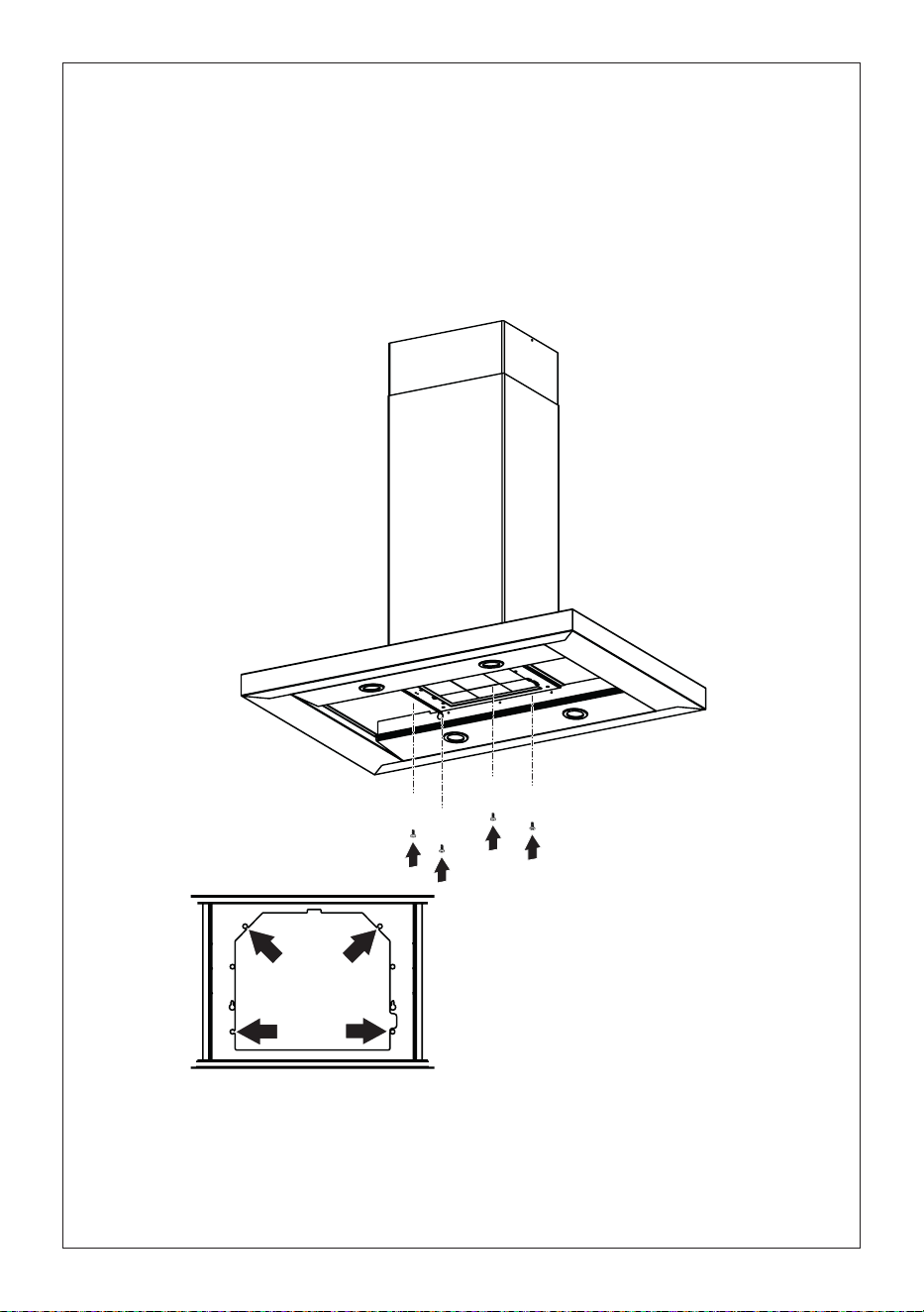
10
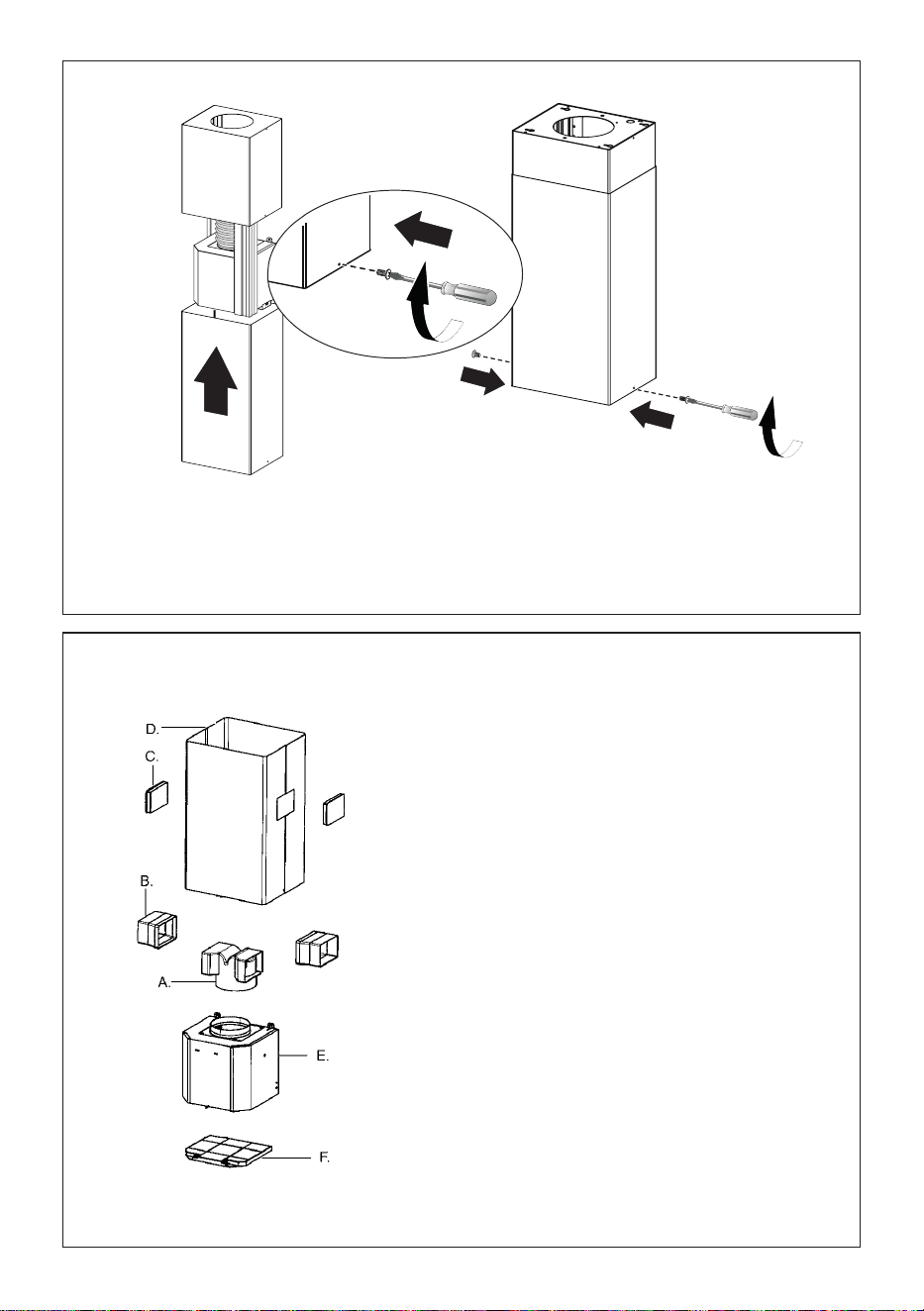
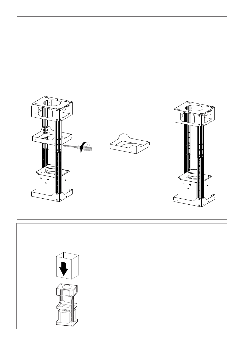
Chimney Flues Must Be Removed Before Installing the Hood
2
3
4
Loosen the two screws fastening the
lower chimney and remove this from
the lower frame.
If you need to adjust the height of the
frame, proceed as follows:
• Unfasten the metric screws joining
the two columns, located at the sides
of the frame (1,2,3,4,5,6).
• Adjust the frame to the height
required, then refit all the screws
removed as above.
Loosen the two screws fastening the
upper chimney and remove this from
the upper frame.
1
4
MIN
740
mm
MAX
940
mm
2
3
5
6
0,10$;
11
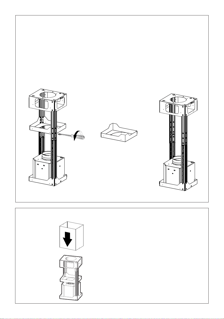
14. REMOVING THE MIDDLE TRESTLE COMPONENT
NOTE: The chimney structure can reduce down to a 27 " minimum height. To reduce the height,
the middle section of the support structure needs to be removed.
Out of the box, the minimum chimney length is 32 ".
Insure the the installation process outlined in the U&C is followed and there is sufficient stability with the
middle section removed.
5
NOTE: The chimney structure can reduce down to a 27 " minimum height. To
reduce the height,
the middle section of the support structure needs to be removed.
Out of the box, the minimum chimney length is 32 ".
Insure the the installation process outlined in the U&C is followed and there is
sufficient stability with the
middle section removed.
REMOVING THE MIDDLE TRESTLE COMPONENT
6
After the regulation for height
adjustment, insert the upper chimney
stack from above, and leave it running
free on the frame.
Upper Flue Must Be In Place Before Proceeding
12
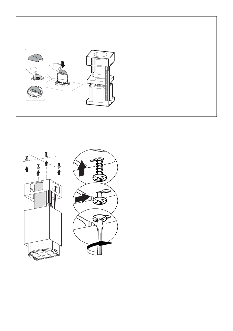
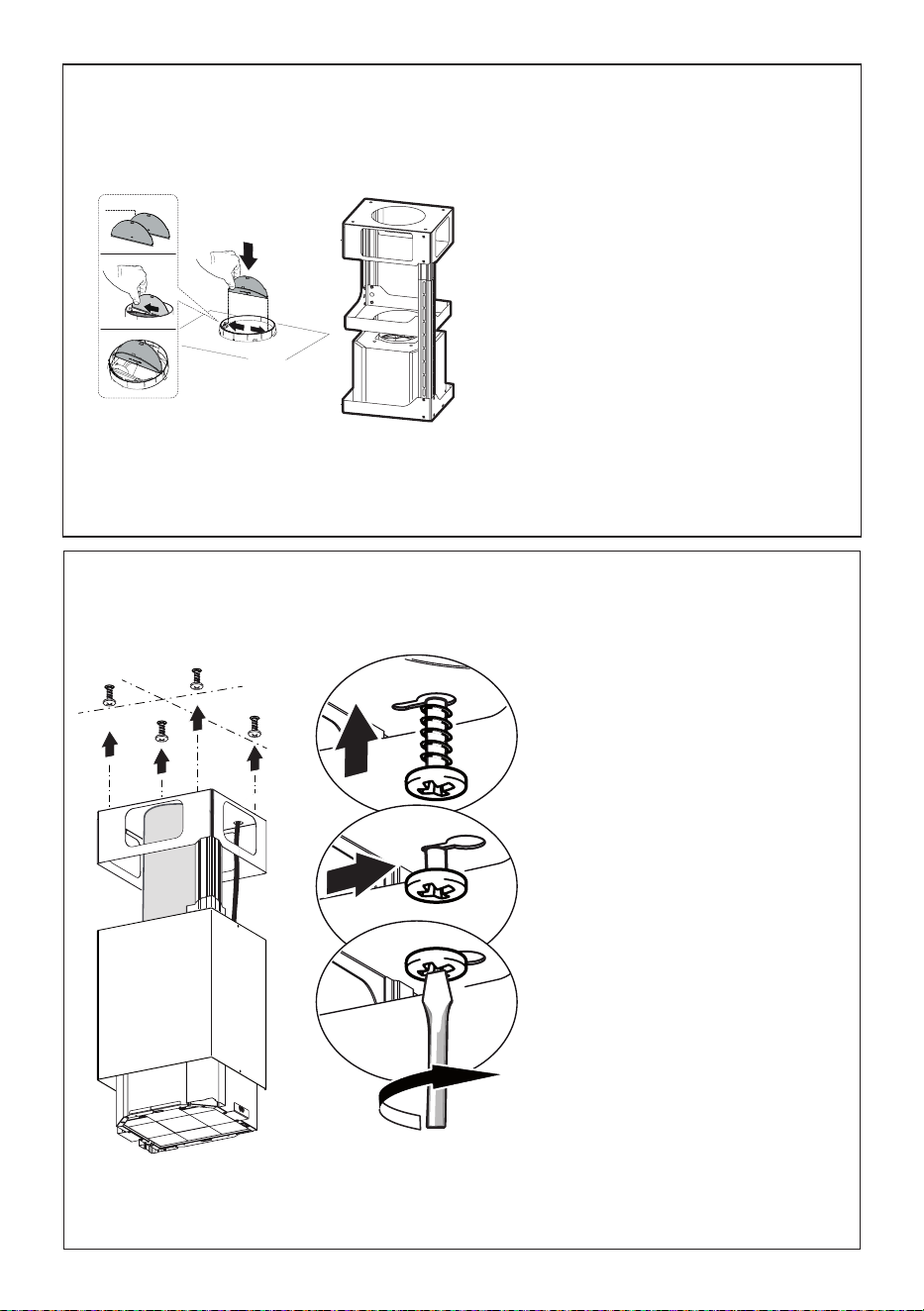
7
Install the Damper flaps 10 that are
included with hood by snapping the
tabs into place inside the top of the
hood before connecting ductwork.
Only for Ducted Venting Installation
8
Now take either your wood screws or
bolts depending on your set-up and
screw all four into the pilot holes and
leave 1/4" of the heads exposed.
Next install a UL or CSA listed strain
relief in the wiring box so that the
screws can be tightened after the
chimney support is attached to the
ceiling.
Now lift the chimney support into it's
final position and feed the electrical
supply through the strain relief.
Next position the chimney support
so that the large end of the keyhole
slots are over the ceiling attachment
screws or bolts. Then push the chimney
support so that the bolts are in the neck
of the slots. Tighten all four screws or
bolts securely.
• The frame mountings must be secure
to withstand the weight of the hood
and any stresses caused by the
occasional side thrust applied to the
device. On completion, check that
the base is stable, even if the frame
is subjected to bending.
• In all cases where the ceiling is not
strong enough at the suspension
point, the installer must provide
strengthening using suitable plates
and backing pieces anchored to the
structurally sound parts.
10
13
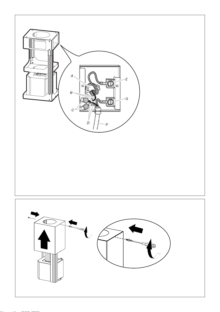
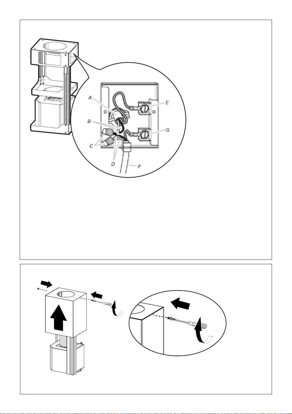
Installation of wiring
connection
Remove the cover from
the field wiring compart-
ment.
DO NOT turn on the
power until installation is
complete!
Connect the Power Sup-
ply Cable to the range-
hood.
Connect the Green
(Green and Yellow)
ground wire under the
Green grounding screw.
Attach the White lead of
the power supply to the
White lead of the range-
hood with a twist-on
type wire connector.
Attach the Black lead of
the power supply to the
Black lead of the range-
hood with a twist-on
type wire connector.
Replace the field wiring
compartment cover and
the grease filters.
A.Home power supply cable
B. Black wires
C. UL listed wire connectors
D. White wires
E. Green (or bare) ground wire from home power
supply connected to green ground screw
F. Range hood power supply cable
G.Range hood power supply cable connected to
green ground screw
Version 02/12 - Page 8
FIGURE 13
MAKE THE ELECTRICAL CONNECTION
Remove the cover from the eld wiring compartment. (SEE
FIGURE 11) DO NOT turn on the power until installation is
complete! Connect the Power Supply Cable to the rangehood.
Connect the Green (Green and Yellow) ground wire under the
Green grounding screw. Attach the White lead of the power
supply to the White lead of the rangehood with a twist-on type
wire connector. Attach the Black lead of the power supply
to the Black lead of the rangehood with a twist-on type wire
connector.
1. The UPPER CHIMNEY
COVER (C in FIGURE 13)
attaches to the top of the
support structure using two
screws provided (G in FIGURE
13). If using the High Ceiling
Chimney Kit, use the UPPER
CHIMNEY COVER supplied
with the kit. Slide up and
attach the UPPER CHIMNEY
COVER.
2. Attach the duct work to the
DAMPER (M in FIGURE 1).
Make sure to seal all joints with
duct tape to prevent leaks.
3. The LOWER CHIMNEY
COVER (B in FIGURE 13)
attaches using two screws
provided (G in FIGURE 13).
Install the LOWER CHIMNEY
COVER by sliding it up over
the support and the UPPER
CHIMNEY COVER.
For ductless installations, line up the DUCTLESS DIVERTER
EXTENSIONS HORIZONTAL (B in FIGURE 12) with the holes
in the LOWER CHIMNEY COVER (D in FIGURE 12) and snap
in the VENT GRIDS (C in FIGURE 12).
INSTALLING THE RANGEHOOD
A. Home power supply cable
B. Black wires
C. UL listed wire connectors
D.White wires
E. Green (or bare) ground wire from home power supply
connected to green ground screw
F. Range hood power supply cable
G.Range hood power supply cable connected to green
ground screw
FIGURE 11
Ductless installations require
a Ductless Conversion
Kit whose components are
pictured in FIGURE 12. Do
not use the DAMPER (M
in FIGURE 1) for ductless
installations. The LOWER
CHIMNEY COVER ( B
in FIGURE 1) should be
discarded and replaced by
the new one with holes from
the Ductless Conversion Kit
(D in FIGURE 12).
As indicated in FIGURE
12, place the DUCTLESS
DIVERTER (A) over the
exhaust opening of the EASY
CUBE (E). Fit the DUCTLESS
DIVERTER EXTENSIONS
HORIZONTAL (B) into the
DIVERTER (A).
FIGURE 12
FOR DUCTLESS INSTALLATIONS
9
10
Position the upper chimney section and fix the upper part to the frame using
the 2 screws removed previously.
Attachment of Upper and Lower Flues
14
12
Similarly, position the lower chimney section and fix the lower part to the
frame using the 2 screws removed previously.
11
Only For Ductless
Installations
Version 02/12 - Page 8
FIGURE 13
MAKE THE ELECTRICAL CONNECTION
Remove the cover from the eld wiring compartment. (SEE
FIGURE 11) DO NOT turn on the power until installation is
complete! Connect the Power Supply Cable to the rangehood.
Connect the Green (Green and Yellow) ground wire under the
Green grounding screw. Attach the White lead of the power
supply to the White lead of the rangehood with a twist-on type
wire connector. Attach the Black lead of the power supply
to the Black lead of the rangehood with a twist-on type wire
connector.
1. The UPPER CHIMNEY
COVER (C in FIGURE 13)
attaches to the top of the
support structure using two
screws provided (G in FIGURE
13). If using the High Ceiling
Chimney Kit, use the UPPER
CHIMNEY COVER supplied
with the kit. Slide up and
attach the UPPER CHIMNEY
COVER.
2. Attach the duct work to the
DAMPER (M in FIGURE 1).
Make sure to seal all joints with
duct tape to prevent leaks.
3. The LOWER CHIMNEY
COVER (B in FIGURE 13)
attaches using two screws
provided (G in FIGURE 13).
Install the LOWER CHIMNEY
COVER by sliding it up over
the support and the UPPER
CHIMNEY COVER.
For ductless installations, line up the DUCTLESS DIVERTER
EXTENSIONS HORIZONTAL (B in FIGURE 12) with the holes
in the LOWER CHIMNEY COVER (D in FIGURE 12) and snap
in the VENT GRIDS (C in FIGURE 12).
INSTALLING THE RANGEHOOD
A. Home power supply cable
B. Black wires
C. UL listed wire connectors
D.White wires
E. Green (or bare) ground wire from home power supply
connected to green ground screw
F. Range hood power supply cable
G.Range hood power supply cable connected to green
ground screw
FIGURE 11
Ductless installations require
a Ductless Conversion
Kit whose components are
pictured in FIGURE 12. Do
not use the DAMPER (M
in FIGURE 1) for ductless
installations. The LOWER
CHIMNEY COVER ( B
in FIGURE 1) should be
discarded and replaced by
the new one with holes from
the Ductless Conversion Kit
(D in FIGURE 12).
As indicated in FIGURE
12, place the DUCTLESS
DIVERTER (A) over the
exhaust opening of the EASY
CUBE (E). Fit the DUCTLESS
DIVERTER EXTENSIONS
HORIZONTAL (B) into the
DIVERTER (A).
FIGURE 12
FOR DUCTLESS INSTALLATIONS
Ductless installations require a
Ductless Conversion Kit whose
components are pictured in
FIGURE 12.
Do not use the DAMPER for
ductless installations. The
LOWER CHIMNEY COVER
should be discarded and
replaced by the new one
with holes from the Ductless
Conversion Kit (D in FIGURE 12).
As indicated in FIGURE 12,
place the DUCTLESS DIVERTER
(A) over the exhaust opening
of the EASY CUBE (E). Fit
the DUCTLESS DIVERTER
EXTENSIONS HORIZONTAL (B)
into the DIVERTER (A).
15
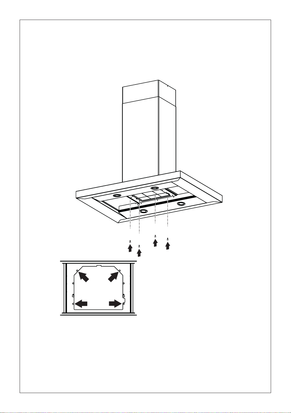
13
Remove the grease filters from the hood canopy.
Remove any activated charcoal filters.
Working from below, fix the hood canopy to the frame where indicated, using
the 4 screws 12q, then tighten all the screws securely.
Attachment of Hood Canopy
I
I
T[
[
16
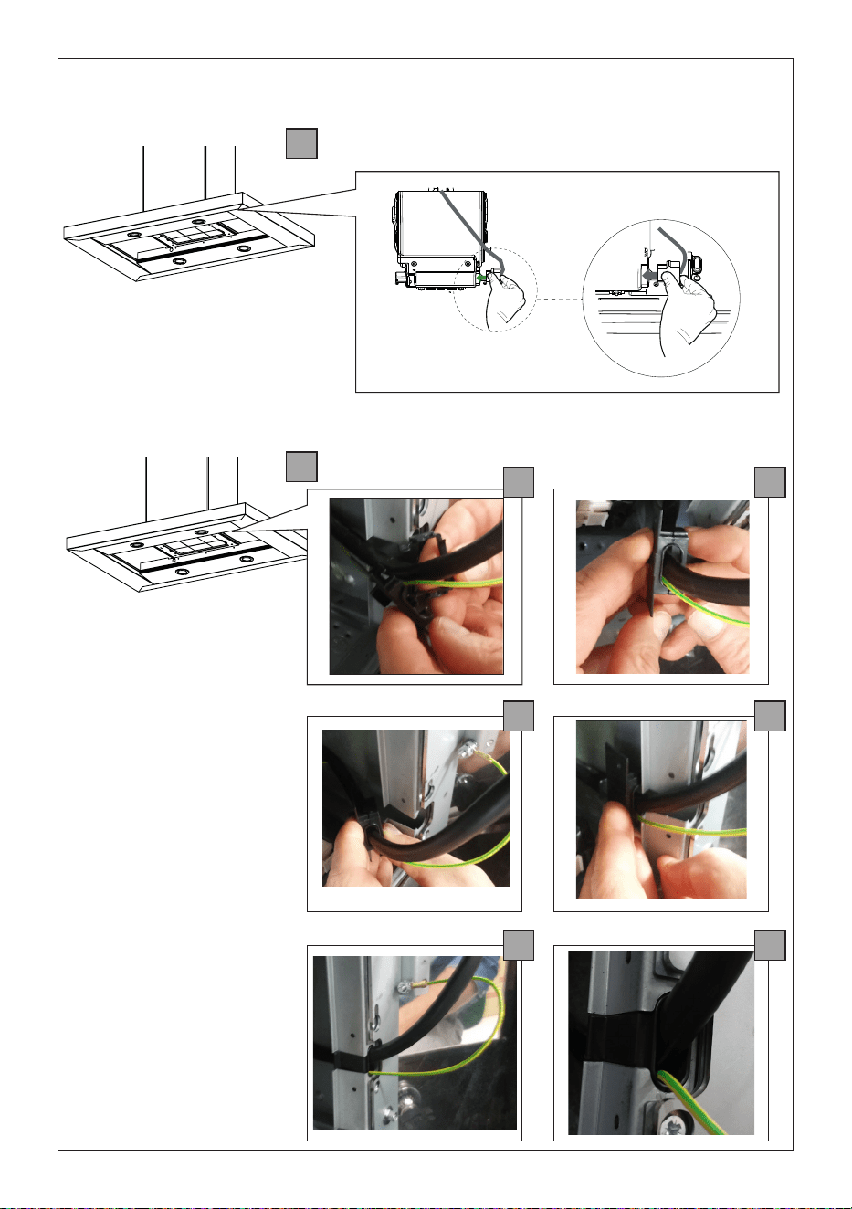
1
2
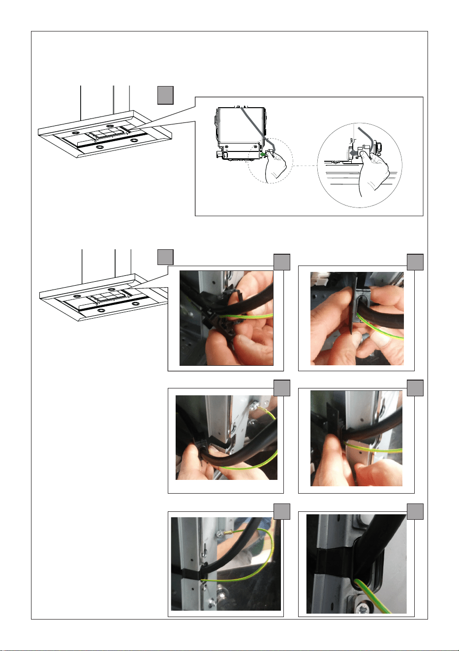
14
Fix the Cable
at the space
indicated with
the lastic fixing
cable component
11 as shown
without stress the
wiring, grounding
included.
Connect the connector of cable
from the Hood Body to the
Blower as shown.
Make the Internal Electrical Connection
a
c
e
b
d
f
17
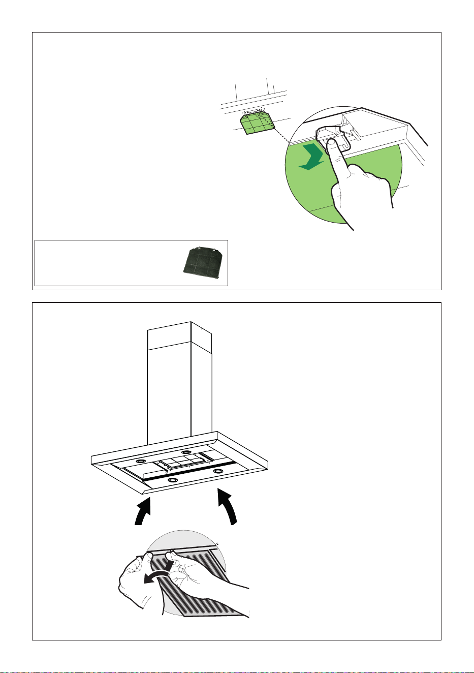
15
For Non-Ducted Recirculation
Option
Attach a
charcoal filter
in the correct
position and
block it by the
fixing hooks as
shown.
Unlock the fixing hooks (towards the back
of the insert hood) to remove.
Reinstall the metal
grease filters from the
hood canopy.
16
Required Activated Charcoal Filter
Accessory - sku # - FILTER2.
18
USE AND CARE INFORMATION
FOR BEST RESULTS
Start the Range Hood several minutes before cooking to develop proper
airflow. Allow the Range Hood to operate for several minutes after cook-
ing is complete to clear all smoke and odors from the kitchen.
NOTE: If your product has had a CFM adjustment, refer to the CFM adjustment manual for
the information. Some motor speeds or functions may be reduced.
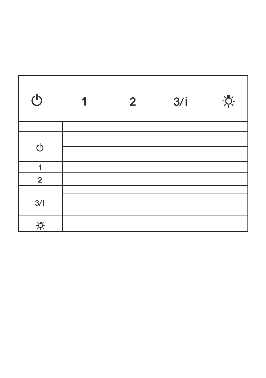
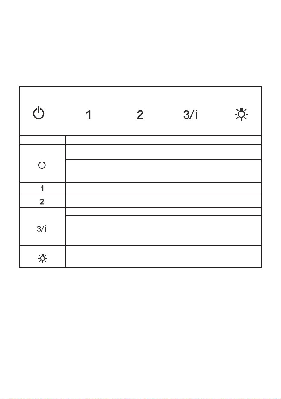
T1 T2 T3 T4 L
Button Function
T1 T2 T3 T4 L
Fan Off Button:Turn the blower Off. The fan can be operated by pressing any of
the fan setting buttons.
Hold down this button for 2 seconds to activate delayed off function which will
keep the fan On for 15 minutes and automatically shut Off.
T1 T2 T3 T4 L
Fan Settings Buttons: Low Speed.
T1 T2 T3 T4 L
Fan Settings Buttons: Medium Speed.
T1 T2 T3 T4 L
Fan Settings Buttons: High Speed.
Hold down the button for 2 seconds to activate the INTENSIVE SPEED, which is
timed to run for 10 minutes. At the end of this time it will automatically return to
the speed set before.Suitable to deal with maximum levels of cooking fumes.
T1 T2 T3 T4 L
Light Button: On/Off switch for the Led lights.
Press the LIGHT button to turn the light on, and again to turn off.
19
Cleaning metal grease filters
The filters must be cleaned every 2 months
of operation, or more frequently for par-
ticularly heavy usage, and can be washed
in a dishwasher.
• Remove the filters one at a time by sup-
porting them with one hand and turning
the safety knobs (pull and turn).
• Wash the Filters without bending them,
and leave them to dry completely be-
fore replacing. (If the surface of the filter
changes color as time goes by, this will
have absolutely no effect on the efficiency
of the filter itself.)
• Refit them and fix them using the safety
knobs pro-vided (pull and turn).
• No water can be present in filters before
installing back in hood.
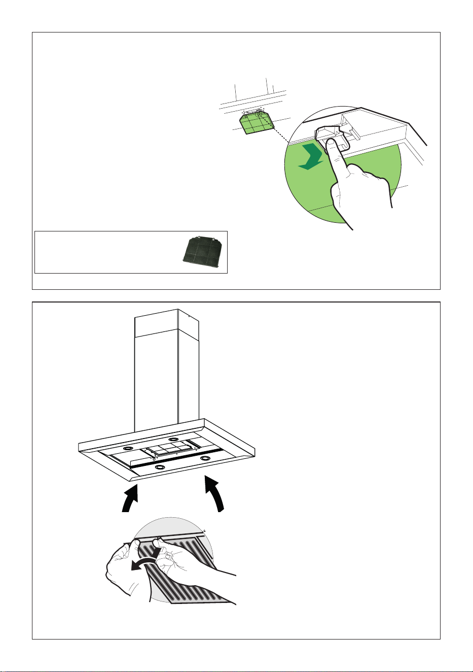
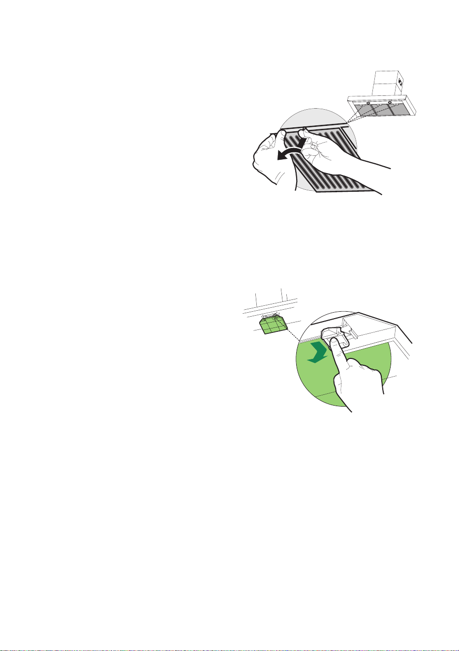
Replacing Activated Charcoal Filter
The filter is not washable and cannot be
regenerated, and must be replaced ap-
proximately every 4 months of operation,
or more frequently for particularly heavy
usage.
• Remove the Filters one at a time, pushing
them towards the back of the unit and at
the same time pulling downward.
• Remove the saturated charcoal filter by
releasing the fixing hooks.
• Fit the new filter and fasten it in its cor-
rect position.
• Replace, taking care to ensure that the
handle faces forwards.
Caution: "When used in recirculation mode,
to Reduce the Risk of Fire and Shock use only
conversion kit Model FILTER2".
Lighting unit
• LED lights must be replaced by Faber
factory authorized service.

20
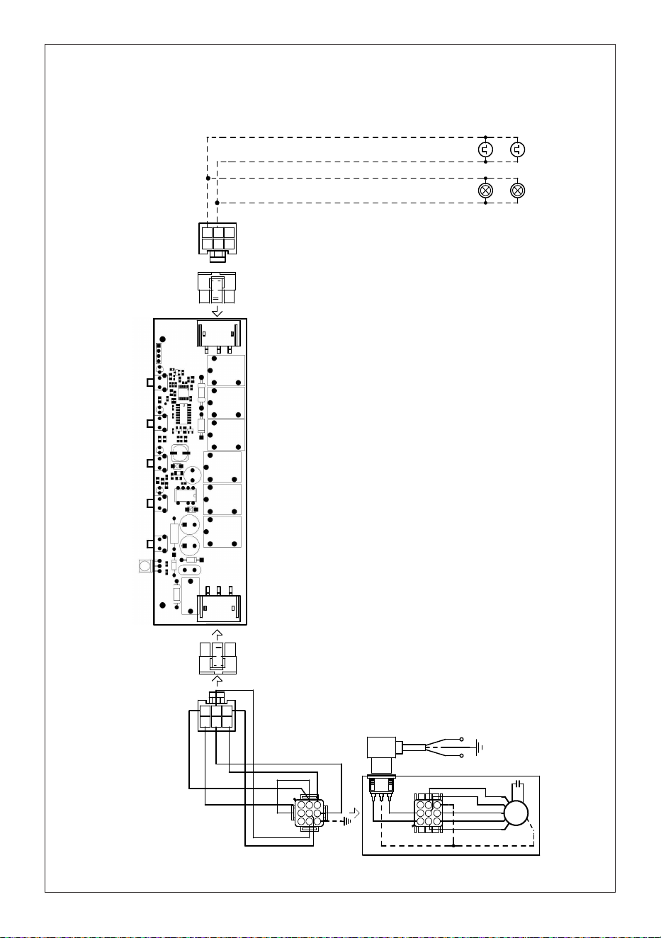
Wiring Diagram
991.0530.011 H90-503
D00004494_00
991.0530.011 H90-503
D00004494_00
120V
60Hz

21
WARRANTY
Franke Home Solutions Warranty for Franke and Faber Branded Product
Effective March 1, 2022
In the United States, Canada and Latin America, Franke warrants the Faber branded products from manufacturing defects
in material and workmanship when purchased from a Franke or Faber Authorized Retailer pursuant to product-specific
warranties detailed herein (each, a “Warranty” and collectively, the “Warranties”). The products must be properly installed,
per Franke’s installation instructions, in their original installation, and used in normal indoor residential kitchen
applications. Any products or components which have been modified or altered from their original intended condition will
void the Warranty. The Franke Warranties for Faber branded products are limited to the original purchaser and are non-
transferrable. These Warranties do not include products purchased from non-Authorized Retailers, products that are
obsolete or discontinued, or products that were previous display models. All issues with installed products are considered
warranty claims and not subject to the Return Policy. Franke reserves the right to inspect any Franke / Faber product
reported to be defective pursuant to a Warranty claim and the original installation prior to providing a replacement product
and/or component. All decisions are final. In no situation shall the liability of Franke exceed the amount of the original
purchase price.
The Warranties do not cover, and Franke shall not be liable for, any damage to products or components resulting from
misuse or abuse, accidental damages, normal wear such as scuffs, scratches or finish reduction/fading, improper
installation, abnormal usage, negligence, damage caused by improper maintenance or cleaning. Damage caused by
impurities, corrosive chemicals or acts beyond Franke’s control are not covered by any Warranty. Service calls to correct
the installation of a range hood, instructions on how to operate a range hood, to replace or repair house fuses or to correct
house wiring or plumbing are not covered by any Warranty. Service calls to repair or replace range hood light bulbs, fuses
or filters and these consumable part costs are also excluded from Warranty coverage. Installation not in accordance with
electrical or plumbing codes or Franke / Faber documentation are not covered by any Warranty. Replacement parts or
repair labor costs for units operated outside the United States, Canada or Latin America, including any non-UL or C-UL or
non-NOM approved Franke / Faber range hoods are excluded from Warranty coverage. Expenses for travel and
transportation for service in remote locations and pickup and delivery charges are not covered by any Warranty. Franke /
Faber range hoods should always be serviced in the home in their original installation.
Franke / Faber product replacements do not include liability for project delays. Product replacements are not guaranteed
to be exact replacements. If the original product is not available at the time of the warranty claim, at Franke’s option, the
product replacements will be of similar size, material, and value. Any products or components which have been modified
or altered, from its original intended condition will void the warranty.
The Warranties do not allow recovery of incidental or consequential damages such as loss of use, delay, property
damage or other consequential damage, and Franke accepts no liability for such damages. Each Warranty is limited to
the conditions set forth herein and to the applicable warranty period specified herein and is exclusive. EXCEPT FOR THE
WARRANTIES SET FORTH HEREIN, FRANKE MAKES NO WARRANTY WHATSOEVER WITH RESPECT TO THE
PRODUCTS, INCLUDING, BUT NOT LIMITED TO, (1) ANY WARRANTY OF MERCHANTABILITY, (2) WARRANTY OF
FITNESS FOR A PARTICULAR PURPOSE, (3) WARRANTY OF TITLE, OR (4) WARRANTY AGAINST INFRINGEMENT
OF INTELLECTUAL PROPERTY RIGHTS OF A THIRD PARTY, WHETHER EXPRESS OR IMPLIED BY LAW, COURSE
OF DEALING, COURSE OF PERFORMANCE, USAGE OF TRADE OR OTHERWISE. LEGAL DISCLAIMER PLEASE
READ CAREFULLY. Franke Kitchen Systems LLC provides the above information to you as a public service to our
customers. By accessing and using this information, you agree to the following and to comply with all applicable laws. If
you do not agree with these terms and conditions, do not use this information. While we try to keep the information
current, changes may have occurred since its creation. Contact your Regional Manager or Customer Service to verify
information regarding Franke Kitchen Systems LLC programs and their use by you.
Franke / Faber Range Hood Limited Warranty:
Franke / Faber range hoods are warranted against any defect in materials or workmanship for the original purchaser for a
period of two (2) years from the date of original purchase when used in standard residential indoor applications. This
warranty covers labor and replacement parts. Franke, at its option, may repair or replace the product or components
necessary to restore the product to good working condition.
Franke Home Solutions Warranty for Franke and Faber Branded Product Effective March 1, 2022
In the United States, Canada and Latin America, Franke warrants the Faber branded products from manufacturing defects
in material and workmanship when purchased from a Franke or Faber Authorized Retailer pursuant to product-specific
warranties detailed herein (each, a “Warranty” and collectively, the “Warranties”). The products must be properly installed, per
Franke’s installation instructions, in their original installation, and used in normal indoor residential kitchen applications. Any
products or components which have been modified or altered from their original intended condition will void the Warranty.
The Franke Warranties for Faber branded products are limited to the original purchaser and are non- transferrable. These
Warranties do not include products purchased from non-Authorized Retailers, products that are obsolete or discontinued, or
products that were previous display models. All issues with installed products are considered warranty claims and not subject
to the Return Policy. Franke reserves the right to inspect any Franke / Faber product reported to be defective pursuant to a
Warranty claim and the original installation prior to providing a replacement product and/or component. All decisions are final.
In no situation shall the liability of Franke exceed the amount of the original purchase price.
The Warranties do not cover, and Franke shall not be liable for, any damage to products or components resulting from misuse
or abuse, accidental damages, normal wear such as scuffs, scratches or finish reduction/fading, improper installation, abnormal
usage, negligence, damage caused by improper maintenance or cleaning. Damage caused by impurities, corrosive chemicals
or acts beyond Franke’s control are not covered by any Warranty. Service calls to correct the installation of a range hood,
instructions on how to operate a range hood, to replace or repair house fuses or to correct house wiring or plumbing are not
covered by any Warranty. Service calls to repair or replace range hood light bulbs, fuses or filters and these consumable part
costs are also excluded from Warranty coverage. Installation not in accordance with electrical or plumbing codes or Franke
/ Faber documentation are not covered by any Warranty. Replacement parts or repair labor costs for units operated outside
the United States, Canada or Latin America, including any non-UL or C-UL or non-NOM approved Franke / Faber range hoods
are excluded from Warranty coverage. Expenses for travel and transportation for service in remote locations and pickup and
delivery charges are not covered by any Warranty. Franke / Faber range hoods should always be serviced in the home in their
original installation.
Franke / Faber product replacements do not include liability for project delays. Product replacements are not guaranteed to
be exact replacements. If the original product is not available at the time of the warranty claim, at Franke’s option, the product
replacements will be of similar size, material, and value. Any products or components which have been modified or altered,
from its original intended condition will void the warranty.
The Warranties do not allow recovery of incidental or consequential damages such as loss of use, delay, property damage or
other consequential damage, and Franke accepts no liability for such damages. Each Warranty is limited to the conditions set
forth herein and to the applicable warranty period specified herein and is exclusive. EXCEPT FOR THE WARRANTIES SET
FORTH HEREIN, FRANKE MAKES NO WARRANTY WHATSOEVER WITH RESPECT TO THE PRODUCTS, INCLUDING, BUT
NOT LIMITED TO, (1) ANY WARRANTY OF MERCHANTABILITY, (2) WARRANTY OF FITNESS FOR A PARTICULAR PURPOSE,
(3) WARRANTY OF TITLE, OR (4) WARRANTY AGAINST INFRINGEMENT OF INTELLECTUAL PROPERTY RIGHTS OF A
THIRD PARTY, WHETHER EXPRESS OR IMPLIED BY LAW, COURSE OF DEALING, COURSE OF PERFORMANCE, USAGE OF
TRADE OR OTHERWISE. LEGAL DISCLAIMER PLEASE
READ CAREFULLY. Franke Kitchen Systems LLC provides the above information to you as a public service to our customers.
By accessing and using this information, you agree to the following and to comply with all applicable laws. If you do not agree
with these terms and conditions, do not use this information. While we try to keep the information current, changes may have
occurred since its creation. Contact your Regional Manager or Customer Service to verify information regarding Franke Kitchen
Systems LLC programs and their use by you.
Franke / Faber Range Hood Limited Warranty:
Franke / Faber range hoods are warranted against any defect in materials or workmanship for the original purchaser for a
period of two (2) years from the date of original purchase when used in standard residential indoor applications. This warranty
covers labor and replacement parts. Franke, at its option, may repair or replace the product or components necessary to
restore the product to good working condition.

22
Franke Home Solutions Warranty for Franke and Faber Branded Product
Effective March 1, 2022
In the United States, Canada and Latin America, Franke warrants the Faber branded products from manufacturing defects
in material and workmanship when purchased from a Franke or Faber Authorized Retailer pursuant to product-specific
warranties detailed herein (each, a “Warranty” and collectively, the “Warranties”). The products must be properly installed,
per Franke’s installation instructions, in their original installation, and used in normal indoor residential kitchen
applications. Any products or components which have been modified or altered from their original intended condition will
void the Warranty. The Franke Warranties for Faber branded products are limited to the original purchaser and are non-
transferrable. These Warranties do not include products purchased from non-Authorized Retailers, products that are
obsolete or discontinued, or products that were previous display models. All issues with installed products are considered
warranty claims and not subject to the Return Policy. Franke reserves the right to inspect any Franke / Faber product
reported to be defective pursuant to a Warranty claim and the original installation prior to providing a replacement product
and/or component. All decisions are final. In no situation shall the liability of Franke exceed the amount of the original
purchase price.
The Warranties do not cover, and Franke shall not be liable for, any damage to products or components resulting from
misuse or abuse, accidental damages, normal wear such as scuffs, scratches or finish reduction/fading, improper
installation, abnormal usage, negligence, damage caused by improper maintenance or cleaning. Damage caused by
impurities, corrosive chemicals or acts beyond Franke’s control are not covered by any Warranty. Service calls to correct
the installation of a range hood, instructions on how to operate a range hood, to replace or repair house fuses or to correct
house wiring or plumbing are not covered by any Warranty. Service calls to repair or replace range hood light bulbs, fuses
or filters and these consumable part costs are also excluded from Warranty coverage. Installation not in accordance with
electrical or plumbing codes or Franke / Faber documentation are not covered by any Warranty. Replacement parts or
repair labor costs for units operated outside the United States, Canada or Latin America, including any non-UL or C-UL or
non-NOM approved Franke / Faber range hoods are excluded from Warranty coverage. Expenses for travel and
transportation for service in remote locations and pickup and delivery charges are not covered by any Warranty. Franke /
Faber range hoods should always be serviced in the home in their original installation.
Franke / Faber product replacements do not include liability for project delays. Product replacements are not guaranteed
to be exact replacements. If the original product is not available at the time of the warranty claim, at Franke’s option, the
product replacements will be of similar size, material, and value. Any products or components which have been modified
or altered, from its original intended condition will void the warranty.
The Warranties do not allow recovery of incidental or consequential damages such as loss of use, delay, property
damage or other consequential damage, and Franke accepts no liability for such damages. Each Warranty is limited to
the conditions set forth herein and to the applicable warranty period specified herein and is exclusive. EXCEPT FOR THE
WARRANTIES SET FORTH HEREIN, FRANKE MAKES NO WARRANTY WHATSOEVER WITH RESPECT TO THE
PRODUCTS, INCLUDING, BUT NOT LIMITED TO, (1) ANY WARRANTY OF MERCHANTABILITY, (2) WARRANTY OF
FITNESS FOR A PARTICULAR PURPOSE, (3) WARRANTY OF TITLE, OR (4) WARRANTY AGAINST INFRINGEMENT
OF INTELLECTUAL PROPERTY RIGHTS OF A THIRD PARTY, WHETHER EXPRESS OR IMPLIED BY LAW, COURSE
OF DEALING, COURSE OF PERFORMANCE, USAGE OF TRADE OR OTHERWISE. LEGAL DISCLAIMER PLEASE
READ CAREFULLY. Franke Kitchen Systems LLC provides the above information to you as a public service to our
customers. By accessing and using this information, you agree to the following and to comply with all applicable laws. If
you do not agree with these terms and conditions, do not use this information. While we try to keep the information
current, changes may have occurred since its creation. Contact your Regional Manager or Customer Service to verify
information regarding Franke Kitchen Systems LLC programs and their use by you.
Franke / Faber Range Hood Limited Warranty:
Franke / Faber range hoods are warranted against any defect in materials or workmanship for the original purchaser for a
period of two (2) years from the date of original purchase when used in standard residential indoor applications. This
warranty covers labor and replacement parts. Franke, at its option, may repair or replace the product or components
necessary to restore the product to good working condition.
This warranty supersedes all other warranties, expressed or implied. No employee, field sales
representatives, or distribution persons are authorized to give any warranties on behalf of Franke Kitchen
Systems, LLC
To make an installed product warranty claim please contact Franke at the provided contact information
below. All warranty claims must include the following for processing:
1. Proof of purchase from Franke or Faber Authorized Retailer
2. Original purchaser’s name, address (included city, state, zip), email address and phone number
3. Franke / Faber model and serial number
4. Date of installation
5. Description of the defect
6. Photos of the defect
In North America and Latin America:
Franke Home Solutions
Attn: Warranty Department
800 Aviation Parkway
Smyrna, TN 37167
HS-Warranty.US@Franke.com
Legal Entity:
Franke Kitchen Systems LLC

23
LISEZ ET SAUVEGARDEZ CES CONSIGNES AVANT DE COMMENCER
L’INSTALLATION DE CETTE HOTTE DE CUISINIÈRE
AVERTISSEMENT: - POUR RÉDUIRE LE RISQUE D'UN FEU DE GRAISSE SUR LA CUISINIÈRE:
a) Ne laissez jamais les unités de surface sans surveillance à des valeurs de réglage élevés. Les déb-
ordements provoquent des fumées et peuvent s'enflammer s’ils sont graisseux. Faites chauffer
les huiles lentement à feu doux ou moyen.
b) Mettez toujours la hotte EN MARCHE lorsque vous cuisinez à feu vif ou lorsque vous flambez
des mets (par exemple, des crêpes Suzette, des cerises Jubilée, du bœuf au poivre flambé).
c) Nettoyez fréquemment les ventilateurs. La graisse ne doit pas s'accumuler sur le ventilateur ou
le filtre.
d) Utilisez une casserole de taille appropriée. Utilisez toujours des ustensiles de cuisson adaptés à
la taille de l'élément de surface.
AVERTISSEMENT: - POUR RÉDUIRE LES RISQUES DE BLESSURES EN CAS DE FEU DE GRAISSE
SUR LE DESSUS DE LA CUISINIÈRE, RESPECTEZ LES CONSIGNES SUIVANTES*:
a) ÉTOUFFEZ LES FLAMMES avec un couvercle hermétique, une plaque à biscuits ou un plateau
métallique, puis éteignez le brûleur. VEILLEZ A ÉVITER LES BRÛLURES. Si les flammes ne
s'éteignent pas immédiatement, ÉVACUEZ ET APPELEZ LES POMPIERS.
b) Ne RAMASSEZ JAMAIS UNE CASSEROLE ENFLAMMÉE - Vous pourriez vous brûler.
c) N'UTILISEZ PAS D'EAU, y compris des torchons ou des serviettes humides - une violente explo-
sion de vapeur en résulterait.
d) Utilisez un extincteur UNIQUEMENT si:
1. Vous savez que vous avez un extincteur de classe ABC et vous savez déjà comment l'utiliser.
2. Le feu est petit et limité dans la zone où il s’est déclenché.
3. Les pompiers ont été appelés.
4. Vous pouvez combattre le feu en tournant le dos à une sortie.
* Basé sur les «Conseils de sécurité pour la cuisine» publié par laNFPA
AVERTISSEMENT - POUR RÉDUIRE LE RISQUE D'INCENDIE OU DE CHOC ÉLECTRIQUE, n'utilisez
pas ce ventilateur avec un dispositif de contrôle de vitesse à semi-conducteurs.
AVERTISSEMENT - POUR RÉDUIRE LES RISQUES D'INCENDIE, DE CHOC ÉLECTRIQUE OU DE
BLESSURE, RESPECTEZ LES CONSIGNES SUIVANTES:
1. N'utilisez cet appareil que conformément aux instructions du fabricant. Si vous avez des que-
stions, contactez le fabricant.
2. Avant de procéder à l'entretien ou au nettoyage de l'appareil, coupez l'alimentation électrique
au niveau du panneau de service et verrouillez le dispositif de déconnexion de service pour
éviter toute remise sous tension accidentelle. Lorsque vous ne pouvez pas verrouiller le dispo-
sitif de déconnexion du service, fixez solidement un dispositif d'avertissement bien visible, tel
qu'une étiquette, sur le panneau de service.
ATTENTION: Pour une utilisation générale de ventilation seulement. Ne l’utilisez pas pour évacuer
des matières et des vapeurs dangereuses ou explosives.
AVERTISSEMENT - POUR RÉDUIRE LES RISQUES D'INCENDIE, DE CHOC ÉLECTRIQUE OU DE
BLESSURE, RESPECTEZ LES CONSIGNES SUIVANTES:
1. Confiez les travaux d'installation et le câblage électrique à une ou plusieurs personnes qualifiées,
conformément à tous les codes et normes en vigueur, y compris les constructions résistantes
au feu. Une quantité suffisante d'air est nécessaire pour une bonne combustion et l'évacuation
des gaz par le conduit (cheminée) de l'équipement de combustion afin d'éviter le refoulement.
Suivez les directives du fabricant de l'équipement de chauffage et les normes de sécurité telles
que celles publiées par la National Fire Protection Association (NFPA) et l'American Society
for Heating, Refrigeration and Air Conditioning Engineers (ASHRAE), ainsi que les autorités
locales chargées du code.
2. Lorsque vous coupez ou percez un mur ou un plafond, n'endommagez pas le câblage électrique
24
et les raccordements aux services utilitaires cachés.
3. Les ventilateurs à conduit doivent toujours être évacués vers l'extérieur.
TOUTES LES OUVERTURES DANS LES PAROIS ET LE PLANCHER OÙ LA HOTTE EST
INSTALLÉE DOIVENT ÊTRE SCELLÉES.
Cette hotte nécessite un dégagement d’au moins 24" entre le bas de la hotte et la surface de cuisson
ou le comptoir. Elle a été approuvée par les LA à cette distance de la table de cuisson.
Ce dégagement minimum peut être plus élevé selon les codes du bâtiment locaux. Pour les tables de
cuisson au gaz et les cuisinières combinées, un minimum de 30" est recommandé et peut être exigé.
Les armoires suspendues des deux côtés de l’appareil doivent se trouver à au moins 18" au-dessus de
la surface de cuisson ou du comptoir. Consultez les instructions d'installation de la table de cuisson ou
de la cuisinière données par le fabricant avant de faire des découpes.
INSTALLATION DANS DES MOBIL-HOMES L’installation de cette hotte de cuisine doit être conforme
aux normes de construction et de sécurité des maisons mobiles, titre 24 CFR, partie 3280 (anciennement
norme fédérale pour la construction et la sécurité des mobil-homes, titre 24, HUD, partie 280). Voir
Exigences électriques.
EXIGENCES EN MATIÈRE DE VENTILATION
Déterminez la méthode de ventilation qui convient le mieux à votre application. Les conduits peuvent
passer soit par le mur, soit par le toit.
La longueur des conduits et le nombre de coudes doivent être réduits au minimum pour assurer une
performance efficace. La taille des conduits doit être uniforme. N'installez pas deux coudes ensemble.
Utilisez du ruban adhésif pour sceller tous les joints du système de conduits. Utilisez du calfeutrage
pour sceller l'ouverture du mur extérieur ou du plancher autour du capuchon.
Les conduits flexibles ne sont pas recommandés. Ils créent une contre-pression et des turbulences
d'air qui réduisent considérablement les performances.
Assurez-vous qu'il y a un dégagement approprié dans le mur ou le plancher pour le conduit d'évacuation
avant de faire des découpes. Ne coupez pas une solive ou un montant à moins que cela ne soit absolu-
ment nécessaire. Si vous devez couper une solive ou un montant, veuillez construire un cadre de support.
AVERTISSEMENT - Pour réduire les risques d'incendie, utilisez uniquement des conduits métalliques.
ATTENTION - Pour réduire les risques d'incendie et pour évacuer correctement l'air, assurez-vous
de canaliser l'air vers l'extérieur - Ne faites pas passer l'air évacué dans des espaces à l'intérieur des
murs ou des plafonds ou dans des greniers, des vides sanitaires ou des garages.
AVERTISSEMENT : Pour réduire les risques d'incendie, d’électrochoc ou de blessure, n'utilisez pas
de pièces de rechange non préconisées par le fabricant (par exemple, des pièces bricolées à la
maison à l'aide d'une imprimante 3D).
• Le système de ventilation DOIT se terminer à l'extérieur de la maison.
• NEPAS faire aboutir le conduit dans un grenier ou un autre espace fermé.
• NEPAS utiliser de capuchons muraux de 4" de type blanchisserie.
• Les conduits de type exible ne sont pas recommandés.
• NEPAS obstruer le ux d'air de combustion et de ventilation.
• Le non-respect des exigences en matière de ventilation peut entraîner un incendie.
AVERTISSEMENT
!
25
INSTALLATION ÉLECTRIQUE AVEC BOÎTIER DE CÂBLAGES
CET APPAREIL DOIT ÊTRE UNIQUEMENT BRANCHÉ À L'AIDE DE FILS DE CUIVRE. Le ca-
libre des fils doit être conforme aux critères de la dernière édition du National Electrical Code,
de l'ANSI/NFPA 70 et de l'ensemble des codes et réglementations en vigueur. Le calibre des
fils et les connexions doivent être adaptés aux caractéristiques nominales de l'appareil. Il est
possible de se procurer un exemplaire des normes indiquées ci-dessus en communiquant avec:
National Fire Protection Association
Batterymarch Park
Quincy, Massachusetts 02269 (États-Unis)
Cet appareil devrait être branché directement au sectionneur à fusible (ou au disjoncteur) par
un câble flexible de cuivre avec blindage ou gaine non métallique. Laissez un peu de jeu dans
le câble pour permettre le déplacement de l'appareil si des travaux d'entretien s'avéraient
nécessaires. Un raccord de conduit homologué par l'UL de 1/2" doit être installé aux deux
extrémités du câble d'alimentation (au niveau de l'appareil et de la boîte de liaison).
Lors de la réalisation du branchement électrique, réalisez un trou de 11/4" dans le mur. S'il
s'agit d'un trou dans le bois, il doit être poncé pour le rendre lisse. S'il s'agit d'un trou dans le
métal, un passe-fils est requis.
EXIGENCESÉLECTRIQUES
Une alimentation électrique de 120volts, 60Hz, uniquement en CA, est requise sur un circuit
séparé à fusible de 15ampères. Nous recommandons un fusible à retardement ou un disjoncteur.
Le fusible doit être dimensionné en fonction des codes locaux et de la puissance électrique
de l'appareil, comme indiqué sur la plaque signalétique située à l'intérieur de l'appareil, près
du compartiment de câblage.
• Une mise à la terre électrique est requise sur cette hotte.
• Si le tube d'eau froide est interrompu par du plastique, des joints non métalliques ou
d'autres matériaux, NE l'utilisez PAS pour la mise à la terre.
• NE mettez PAS à la terre un tube de gaz.
• N’ayez PAS de fusible dans le circuit neutre ou de mise à la terre. Un fusible dans le
circuit neutre ou de mise à la terre pourrait provoquer un choc électrique.
• Vériez auprès d’un électricien qualié si vous avez des doutes quant à la mise à la
terre de la hotte.
• Le non-respect des exigences électriques peut entraîner un incendie.
AVERTISSEMENT
!

26
ATTENTION : Les pièces accessibles peuvent devenir chaudes lorsqu'elles sont
utiliséesavecdesappareilsdecuisson.
•L'airnedoitpasêtreévacuédansunconduitdefuméeutilisépourévacuerles
fuméesdesappareilsbrûlantdugazoud'autrescombustibles.
•SiunAPPAREILSTATIONNAIREn'estpaséquipéd'unCORDD'ALIMENTATIONet
d'uneche,oud'autresmoyensdedéconnexiondusecteurd'alimentationayant
uneséparationdescontactsdanstouslespôlesquipermettentunedéconnexion
complètedansdesconditionsdecatégoriedesurtensionlII,lesinstructionsdoi-
ventindiquerquedesmoyenspourladéconnexiondoitêtreintégréeaucâblage
xeconformémentauxrèglesdecâblage.
•Ladéconnexionpeutêtreréaliséeenrendantlacheaccessibleouenincorporant
uninterrupteurdanslecâblagexeconformémentauxrèglesdecâblage.
• Cet appareil n'estpasdestinéàêtreutilisépardes personnes (y compris des
enfants)dontlescapacitésphysiques,sensoriellesoumentalessontdifférentes
ouréduites,ouquimanquentd'expérienceoudeconnaissances,àmoinsqueces
personnesnesoientsuperviséesouforméespourlefonctionnementdel'appareil
parunepersonneresponsabledeleursécurité.
•Lesenfantsdoiventêtresurveilléspours'assurerqu'ilsn'utilisentpaslesappareils
commeunjouet.
•Neambezpasd'alimentssouslahotte.
•l'airnedoitpasêtreévacuédansunconduitdefuméeutilisépourévacuerles
fuméesd'appareilsbrûlantdugazoud'autrescombustibles(nes'appliquepas
auxappareilsquirejettentuniquementl'airdanslapièce);
•ildoityavoiruneventilationadéquatedelapiècelorsquelahottedecuisineest
utiliséeenmêmetempsquedesappareilsbrûlantdugazoud'autrescombustibles
(nes'appliquepasauxappareilsquirejettentuniquementl'airdanslapièce);
•ilexisteunrisqued'incendiesilenettoyagen'estpaseffectuéconformémentaux
instructions ;
•Cetappareildoitêtremisàlaterre.Encasdecourt-circuitélectrique,lamiseàla
terreréduitlerisquedechocélectriqueenfournissantunldefuitepourlecou-
rantélectrique.Cetappareilestéquipéd'uncordondotéd'unldeterreavecune
chedemiseàlaterre.Lachedoitêtrebranchéedansuneprisecorrectement
installéeetmiseàlaterre.
AVERTISSEMENT-unemiseàlaterreincorrectepeutentraînerunrisquedechoc
électrique.
•Consultezunélectricienqualiésilesinstructionsdemiseàlaterrenesontpas
entièrementcomprisesous'ilexistedesdoutesquantàsavoirsil'appareilest
correctementmisàlaterre.
27
DIMENSIONS DE LA HOTTE
Min. 24" Min. 30"
0,10$;
0,10$;
28
PIÈCES PRINCIPALES
Pièces requises
- Conduit métallique 6" circulaire
Accessoires disponibles
Composants
Réf. Qté Composants du produit
1 1 Bâti de la hotte, avec : Com-
mandes,éclairages,ltres,ventilateur.
2 1 Cheminée télescopique comprenant :
2.1 1 Section supérieure
2.2 1 Section inférieure
7.1 1 Châssis télescopique avec
ventilateur d'aspiration, composé de :
7.1a 1 Châssis supérieur
7.1b 1 Châssis inférieur
10 2 Volets du clapet
11 1 PlastiqueforCâblexation.
Réf. Qté Composants d'installation
12q 4 Vis 1/8" x 1/4"
21 1 Gabarit de perçage
Qté Documentation
1 Mode d'emploi
- Trousse de cheminée pour plafonds hauts, pour remplacer le conduit supèrieur
de cheminée. - No d'article HIGH2.
- Trousse sans conduit - Comprend déflecteur de recyclage, filtres à charbon,
cheminée inférieure avec grille d'évent - No d'article DUCT2
- Filtre à charbon actif accessoire - No d'article FILTER2
- Télécommande sans fil accessoire - REMORIG
10
1
2.2
2.1
21
7.1
12q
7.1a
7.1b
11
29
6 "
Choisissez la méthode de
canalisation
Exige la trousse
d'accessoires sans conduit
(achetée séparément)
Recyclage sans canalisation
Installation avec ventilation
canalisée
30
1
Ø 10 mm
x4
21
1 1/4"
AVERTISSEMENT
!
COMPTE TENU DE LA DI-
MENSION ET DU POIDS DE
CETTE HOTTE, LE SOCLE
DOIT ÊTRE SOLIDEMENT
ANCRÉ AU PLAFOND. Si le
plafond est en plâtre ou en
plaque de plâtre, le socle doit
être ancré aux poutres. Si cela
n'est pas possible, une struc-
ture de soutien doit être con-
struite derrière le plâtre ou la
plaque de plâtre. Le fabricant
ne peut être tenu responsable
en cas de blessures ou de
dommages provoqués par
une mauvaise installation.
Ne pratiquez aucune ouverture avant d'avoir décidé si l'installation sera canalisée
ou non, puis planifiez en conséquence.
Placez une protection épaisse sur la surface
de cuisson, la cuisinière encastrée ou le
comptoir pour éviter les dommages ou
la saleté.
Déterminez l'endroit où la hotte sera
installée et marquez-la clairement sur le
plafond à l'aide d'un crayon.
Un gabarit 21 pour le montage du socle est
fourni dans l'emballage. Utilisez ce modèle
pour indiquer les trous qui serviront à fixer
le socle au plafond.
Déterminez les ouvertures nécessaires pour
les conduits et pratiquez-les. L'ouverture
pour la canalisation est représentée sur le
gabarit de montage. Installez
les conduits avant de monter la hotte.
Déterminez l'emplacement adéquat pour
le câble d'alimentation, comme indiqué
sur le gabarit. Utilisez une mèche de 11/4"
pour percer ce trou. Faites passer le câble
d'alimentation. Utiliser un calfeutrage pour
sceller autour du trou.
Une pièce à défoncer pour le passage de
l'alimentation électrique du plafond est
située au sommet du châssis. Ne branchez
par le câble d'alimentation au boîtier de
connexion et n'alimentez pas la hotte à ce
moment. Acheminez le câble électrique
du plafond jusqu'au boîtier de connexion
sur la hotte.

31
2
3
4
1
4
MIN
740
mm
MAX
940
mm
2
3
5
6
Si vous devez régler la hauteur du châssis, procédez
comme suit :
• Détachez les vis métriques qui unissent les deux
colonnes, situées sur les côtés du châssis (1, 2,
3, 4, 5, 6).
• Réglez le châssis à la hauteur requise, puis
remettez en place toutes les vis enlevées comme
ci-dessus.
Dévissezlesdeuxvisquixentlasectioninférieure
de la cheminée et détachez-la du châssis inférieur.
Dévissezlesdeuxvisquixentlasectionsupérieure
de la cheminée et détachez-la du châssis supérieur.
Les conduits de cheminées doivent être enlevés avant l'installation de la
hotte
0,10$;
32
14. REMOVING THE MIDDLE TRESTLE COMPONENT
NOTE: The chimney structure can reduce down to a 27 " minimum height. To reduce the height,
the middle section of the support structure needs to be removed.
Out of the box, the minimum chimney length is 32 ".
Insure the the installation process outlined in the U&C is followed and there is sufficient stability with the
middle section removed.
5
REMARQUE: La structure de la cheminée peut réduire jusqu'à une hauteur minimale de 27 " . Pour
réduire la hauteur, la section médiane de la structure de support doit être retiré.
Hors de la boîte, la longueur minimale de la cheminée est de 32 ".
Aucun problème du point de vue mécanique, la rigidité est garantie par le chevauchement des colonnes.
RAIT DU COMPOSANT DE TRESTE MOYEN
6
Le conduit supérieur de cheminée doit être en place avant de
poursuivre l'installation
Après avoir procédé au réglage de la hauteur, insérez
la souche de cheminée supérieure à partir du haut
et laissez-la sur le châssis.
33
7
8
Prenez ensuite les vis à bois ou boulons, selon
votre installation, et vissez toutes les quatre dans
les trous d'implantation, en laissant 1/4" de la
tête des vis libre.
Installez ensuite un protège-câbles (homologa-
tion UL ou CSA) dans le boîtier de connexion,
de façon à pouvoir serrer les vis lorsque le socle
de cheminée sera ancré au plafond.
Soulevez ensuite le socle de cheminée à son
emplacement, et faites passer le câble d'ali-
mentation électrique à travers le protège-câbles.
Placez le socle de cheminée de façon à aligner
la grande ouverture des encoches en trou de
serrure sur les vis ou boulons de xation au
plafond. Poussez ensuite le socle de cheminée
de façon à ce que les boulons s'engagent dans
la partie étroite des encoches. Serrez fermement
les quatre vis ou boulons.
• Le montage du châssis doit être assez solide
pour supporter le poids de la hotte et tout stress
causé par une pression latérale occasionnelle
que pourrait subir l'appareil. Lorsque vous avez
terminé, assurez-vous que la base est stable,
même lorsque le châssis est plié.
• Dans tous les cas où le plafond n'est pas
assez fort au point de suspension, l'installateur
doit veiller à le renforcer à l'aide de plaques
et de pièces de renfort ancrées à des pièces
structurelles solides.
Pour installation avec ventilation canalisée uniquement
Installez les volets du clapet 10 qui sont inclus avec
la hotte en enclenchant les languettes à l’intérieur
du haut de la hotte avant de raccorder les conduits.
10
34
9
10
Réalisation des
branchements
Retirez le couvercle du
compartiment des câblages
externes.
NE METTEZ PAS l'alimentation
sous tension avant d'avoir
terminé l'installation!
Branchez le câble d'alimenta-
tion à la hotte.
Branchezlelvert(vertet
jaune) de mise à la terre
sous la vis de mise à la terre
verte.Branchezlelblancde
l'alimentationaulblancdela
hotte à l'aide d'un connecteur
verrouillé par rotation.
Branchezlelnoirdel'alimen-
tationaulnoirdelahotteà
l'aide d'un connecteur verrouillé
par rotation.
Remettez le couvercle du com-
partiment des câblages externes
etlesltresàgraisseenplace.
A. Câble d'alimentation du réseau domestique
B. Fils noirs
C. Serre-fils homologué UL
D. Fils blancs
E. Fil de mise à la terre vert (ou fil nu) de l'alimenta-
tion domestique branché à la vis de mise à la terre
verte
F. Câble d'alimentation de la hotte
G.Câble d'alimentation de la hotte branché à la vis
de mise à la terre verte
Placezlasectionsupérieuredelacheminéeetxezlapartiesupérieureauchâssisàl'aidedes2vis
enlevées précédemment.
Montage des cheminées supérieure et inférieure
Version 02/12 - Page 8
FIGURE 13
MAKE THE ELECTRICAL CONNECTION
Remove the cover from the eld wiring compartment. (SEE
FIGURE 11) DO NOT turn on the power until installation is
complete! Connect the Power Supply Cable to the rangehood.
Connect the Green (Green and Yellow) ground wire under the
Green grounding screw. Attach the White lead of the power
supply to the White lead of the rangehood with a twist-on type
wire connector. Attach the Black lead of the power supply
to the Black lead of the rangehood with a twist-on type wire
connector.
1. The UPPER CHIMNEY
COVER (C in FIGURE 13)
attaches to the top of the
support structure using two
screws provided (G in FIGURE
13). If using the High Ceiling
Chimney Kit, use the UPPER
CHIMNEY COVER supplied
with the kit. Slide up and
attach the UPPER CHIMNEY
COVER.
2. Attach the duct work to the
DAMPER (M in FIGURE 1).
Make sure to seal all joints with
duct tape to prevent leaks.
3. The LOWER CHIMNEY
COVER (B in FIGURE 13)
attaches using two screws
provided (G in FIGURE 13).
Install the LOWER CHIMNEY
COVER by sliding it up over
the support and the UPPER
CHIMNEY COVER.
For ductless installations, line up the DUCTLESS DIVERTER
EXTENSIONS HORIZONTAL (B in FIGURE 12) with the holes
in the LOWER CHIMNEY COVER (D in FIGURE 12) and snap
in the VENT GRIDS (C in FIGURE 12).
INSTALLING THE RANGEHOOD
A. Home power supply cable
B. Black wires
C. UL listed wire connectors
D.White wires
E. Green (or bare) ground wire from home power supply
connected to green ground screw
F. Range hood power supply cable
G.Range hood power supply cable connected to green
ground screw
FIGURE 11
Ductless installations require
a Ductless Conversion
Kit whose components are
pictured in FIGURE 12. Do
not use the DAMPER (M
in FIGURE 1) for ductless
installations. The LOWER
CHIMNEY COVER ( B
in FIGURE 1) should be
discarded and replaced by
the new one with holes from
the Ductless Conversion Kit
(D in FIGURE 12).
As indicated in FIGURE
12, place the DUCTLESS
DIVERTER (A) over the
exhaust opening of the EASY
CUBE (E). Fit the DUCTLESS
DIVERTER EXTENSIONS
HORIZONTAL (B) into the
DIVERTER (A).
FIGURE 12
FOR DUCTLESS INSTALLATIONS

35
12
11
Version 02/12 - Page 8
FIGURE 13
MAKE THE ELECTRICAL CONNECTION
Remove the cover from the eld wiring compartment. (SEE
FIGURE 11) DO NOT turn on the power until installation is
complete! Connect the Power Supply Cable to the rangehood.
Connect the Green (Green and Yellow) ground wire under the
Green grounding screw. Attach the White lead of the power
supply to the White lead of the rangehood with a twist-on type
wire connector. Attach the Black lead of the power supply
to the Black lead of the rangehood with a twist-on type wire
connector.
1. The UPPER CHIMNEY
COVER (C in FIGURE 13)
attaches to the top of the
support structure using two
screws provided (G in FIGURE
13). If using the High Ceiling
Chimney Kit, use the UPPER
CHIMNEY COVER supplied
with the kit. Slide up and
attach the UPPER CHIMNEY
COVER.
2. Attach the duct work to the
DAMPER (M in FIGURE 1).
Make sure to seal all joints with
duct tape to prevent leaks.
3. The LOWER CHIMNEY
COVER (B in FIGURE 13)
attaches using two screws
provided (G in FIGURE 13).
Install the LOWER CHIMNEY
COVER by sliding it up over
the support and the UPPER
CHIMNEY COVER.
For ductless installations, line up the DUCTLESS DIVERTER
EXTENSIONS HORIZONTAL (B in FIGURE 12) with the holes
in the LOWER CHIMNEY COVER (D in FIGURE 12) and snap
in the VENT GRIDS (C in FIGURE 12).
INSTALLING THE RANGEHOOD
A. Home power supply cable
B. Black wires
C. UL listed wire connectors
D.White wires
E. Green (or bare) ground wire from home power supply
connected to green ground screw
F. Range hood power supply cable
G.Range hood power supply cable connected to green
ground screw
FIGURE 11
Ductless installations require
a Ductless Conversion
Kit whose components are
pictured in FIGURE 12. Do
not use the DAMPER (M
in FIGURE 1) for ductless
installations. The LOWER
CHIMNEY COVER ( B
in FIGURE 1) should be
discarded and replaced by
the new one with holes from
the Ductless Conversion Kit
(D in FIGURE 12).
As indicated in FIGURE
12, place the DUCTLESS
DIVERTER (A) over the
exhaust opening of the EASY
CUBE (E). Fit the DUCTLESS
DIVERTER EXTENSIONS
HORIZONTAL (B) into the
DIVERTER (A).
FIGURE 12
FOR DUCTLESS INSTALLATIONS
Delamêmefaçon,placezlasectioninférieuredelacheminéeetxezlapartieinférieureau
châssis à l'aide des 2 vis enlevées précédemment.
Pour installation sans conduit uniquement
L'installation sans conduit nécessite
une Trousse de conversion pour
installation sans conduit dont les
éléments sont représentés à la FIGURE
12.
N'utilisez pas le REGISTRE pour
l'installation sans conduit. L'HABILLAGE
INFÉRIEUR DE CHEMINÉE doit être
remplacé par celui présentant des
trous de la Trousse de conversion pour
installation sans conduit (D sur la
FIGURE 12).
Tel qu'indiqué sur la FIGURE 12, placez
le DÉFLECTEUR DE RECYCLAGE
(A) sur l'ouverture d'évacuation du
EASY CUBE (E). Placez les SORTIES
HORIZONTALES DU DÉFLECTEUR DE
RECYCLAGE (B) dans le DÉFLECTEUR
(A).
36
13
Retirezlesltresàgraissedel'auventdelahotte.
Retireztoutltreàcharbonactif.
Enpassantparledessous,xezl'auventdelahotteauchâssisauxendroitsindiqués,enutilisantles4
vis 12q, puis serrez fermement toutes les vis.
Montage de l'auvent de la hotte
I
I
T[
[
37
14
Réalisation des branchements électriques internes
Fixez le câble à
l’espace indiqué
par le composant
en plastique 11,
comme illustré
sans contrainte le
câblage, mise à la
terre incluse.
Connectez le connecteur du
câble du corps du a hotte au
ventilateur, comme illustré.
a
c
e
b
d
f
1
2
38
15
16
Pour option non canalisée avec recirculation d'air
Posez un filtre
à charbon à
l'emplacement
adéquat et
bloquez-le
à l'aide des
crochets de
fixation, comme
illustré.
Déverrouillez les crochets de fixation (vers
l'arrière de la hotte encastrable) pour les
enlever.
Remettezenplacelesltres
metalliques à graisse de
l'auvent de la hotte.
Filtre à charbon actif accessoire
requis - no d'article - FILTER2
(acheté séparément).
39
INFORMATIONS POUR L'UTILISATION ET L'ENTRETIEN
POURDEMEILLEURSRÉSULTATS
Mettez la hotte en marche plusieurs minutes avant la cuisson pour assu-
rer une bonne circulation de l'air. Laissez la hotte fonctionner pendant
plusieurs minutes après la fin de la cuisson pour évacuer la fumée et les
odeurs de la cuisine.
REMARQUE : Si votre produit a subi un ajustementCFM, reportez-vous au manuel d’aju-
stementCFM pour plus d’informations. Certaines vitesses ou fonctions du moteur peuvent
être réduites.
T1 T2 T3 T4 L
Bouton Fonction
T1 T2 T3 T4 L
Bouton d'arrêt du ventilateur: permet d'arrêter le ventilateur. Il est possible
d’actionner le ventilateur en appuyant sur l'un de ses boutons de réglage.
Maintenez ce bouton enfoncé pendant 2secondes pour activer la fonction d'ar-
rêt différé qui maintient le ventilateur en marche pendant 15minutes et l'arrête
automatiquement.
T1 T2 T3 T4 L
Boutons de réglage du ventilateur: Basse vitesse.
T1 T2 T3 T4 L
Boutons de réglage du ventilateur: Vitesse moyenne.
T1 T2 T3 T4 L
Boutons de réglage du ventilateur: Haute vitesse.
Maintenez le bouton enfoncé pendant 2secondes pour activer la VITESSE IN-
TENSIVE, qui est programmée pour fonctionner pendant 10 minutes. A la n de
cette période, le ventilateur revient automatiquement à la vitesse réglée aupara-
vant, ce qui permet de traiter les niveaux maximums de fumées de cuisson.
T1 T2 T3 T4 L
Bouton d'éclairage: Interrupteur marche/arrêt pour les lumières LED.
Appuyez sur le bouton LIGHT pour allumer la lumière et appuyez à nouveau
pour l’éteindre.

40
Nettoyage des filtres à graisse
métalliques
Lesltresdoiventêtrenettoyéstousles2moisd'utilisation,
ou plus fréquemment en cas d'utilisation particulièrement
intensive. Ils peuvent être lavés dans le lave-vaisselle.
• Décrocherlesltresl’unaprésl’autre,enlessoute-nant
d’une main et en intervenant sur les pommeaux de
sécurité spécialement prévus (tirer et tourner).
• Lavez les ltres sans les plier et laissez-les sécher
complètement avant de les remettre en place. (Si la
surface du ltre change de couleurau ldu temps,
celan'auraaucunimpactsurl'efcacitédultremême.)
• Remonterlesltresenlesxantàl’aidedespom-meaux
de sécurité spécialement prévus (tirer et tour-ner).
• Aucuneeaunepeutêtreprésentedanslesltresavant
la réinstallation dans la hotte.
Remplacement du filtre à charbon
actif
Leltren'estpaslavableetnepeutpasêtrerégénéré.Il
doit être remplacé environ tous les 4 mois d'utilisation, ou
plus souvent en cas d'utilisation particulièrement intensive.
• Retirezlesltresunàun,enlespoussantversl'arrière
de l'appareil et en les tirant vers le bas simultanément.
• Retirez le ltre à charbon saturé en détachant les
crochetsdexation.
• Posez le nouveau ltre et xez-le à l'emplacement
adéquat.
• Remettez-le en place, en vous assurant que la poignée
se trouve vers l'avant.
Attention: "En mode recirculation, pour réduire le
risque d'incendie et de choc, utilisez uniquement le kit de
conversion Modèle FILTER2".
Système d'éclairage
• Les ampoules DEL doivent être remplacées par un
service d'entretien autorisé Faber.
41
991.0530.011 H90-503
D00004494_00
991.0530.011 H90-503
D00004494_00
Schéma de câblage
120V
60Hz

42
GARANTIE
Franke Home Solutions Warranty for Franke and Faber Branded Product
Effective March 1, 2022
In the United States, Canada and Latin America, Franke warrants the Faber branded products from manufacturing defects
in material and workmanship when purchased from a Franke or Faber Authorized Retailer pursuant to product-specific
warranties detailed herein (each, a “Warranty” and collectively, the “Warranties”). The products must be properly installed,
per Franke’s installation instructions, in their original installation, and used in normal indoor residential kitchen
applications. Any products or components which have been modified or altered from their original intended condition will
void the Warranty. The Franke Warranties for Faber branded products are limited to the original purchaser and are non-
transferrable. These Warranties do not include products purchased from non-Authorized Retailers, products that are
obsolete or discontinued, or products that were previous display models. All issues with installed products are considered
warranty claims and not subject to the Return Policy. Franke reserves the right to inspect any Franke / Faber product
reported to be defective pursuant to a Warranty claim and the original installation prior to providing a replacement product
and/or component. All decisions are final. In no situation shall the liability of Franke exceed the amount of the original
purchase price.
The Warranties do not cover, and Franke shall not be liable for, any damage to products or components resulting from
misuse or abuse, accidental damages, normal wear such as scuffs, scratches or finish reduction/fading, improper
installation, abnormal usage, negligence, damage caused by improper maintenance or cleaning. Damage caused by
impurities, corrosive chemicals or acts beyond Franke’s control are not covered by any Warranty. Service calls to correct
the installation of a range hood, instructions on how to operate a range hood, to replace or repair house fuses or to correct
house wiring or plumbing are not covered by any Warranty. Service calls to repair or replace range hood light bulbs, fuses
or filters and these consumable part costs are also excluded from Warranty coverage. Installation not in accordance with
electrical or plumbing codes or Franke / Faber documentation are not covered by any Warranty. Replacement parts or
repair labor costs for units operated outside the United States, Canada or Latin America, including any non-UL or C-UL or
non-NOM approved Franke / Faber range hoods are excluded from Warranty coverage. Expenses for travel and
transportation for service in remote locations and pickup and delivery charges are not covered by any Warranty. Franke /
Faber range hoods should always be serviced in the home in their original installation.
Franke / Faber product replacements do not include liability for project delays. Product replacements are not guaranteed
to be exact replacements. If the original product is not available at the time of the warranty claim, at Franke’s option, the
product replacements will be of similar size, material, and value. Any products or components which have been modified
or altered, from its original intended condition will void the warranty.
The Warranties do not allow recovery of incidental or consequential damages such as loss of use, delay, property
damage or other consequential damage, and Franke accepts no liability for such damages. Each Warranty is limited to
the conditions set forth herein and to the applicable warranty period specified herein and is exclusive. EXCEPT FOR THE
WARRANTIES SET FORTH HEREIN, FRANKE MAKES NO WARRANTY WHATSOEVER WITH RESPECT TO THE
PRODUCTS, INCLUDING, BUT NOT LIMITED TO, (1) ANY WARRANTY OF MERCHANTABILITY, (2) WARRANTY OF
FITNESS FOR A PARTICULAR PURPOSE, (3) WARRANTY OF TITLE, OR (4) WARRANTY AGAINST INFRINGEMENT
OF INTELLECTUAL PROPERTY RIGHTS OF A THIRD PARTY, WHETHER EXPRESS OR IMPLIED BY LAW, COURSE
OF DEALING, COURSE OF PERFORMANCE, USAGE OF TRADE OR OTHERWISE. LEGAL DISCLAIMER PLEASE
READ CAREFULLY. Franke Kitchen Systems LLC provides the above information to you as a public service to our
customers. By accessing and using this information, you agree to the following and to comply with all applicable laws. If
you do not agree with these terms and conditions, do not use this information. While we try to keep the information
current, changes may have occurred since its creation. Contact your Regional Manager or Customer Service to verify
information regarding Franke Kitchen Systems LLC programs and their use by you.
Franke / Faber Range Hood Limited Warranty:
Franke / Faber range hoods are warranted against any defect in materials or workmanship for the original purchaser for a
period of two (2) years from the date of original purchase when used in standard residential indoor applications. This
warranty covers labor and replacement parts. Franke, at its option, may repair or replace the product or components
necessary to restore the product to good working condition.
Garantie Franke Home Solutions pour les produits de marque Franke et Faber en vigueur le 1ermars2022
Aux États-Unis, au Canada et en Amérique latine, Franke garantit les produits de la marque Faber contre les défauts de fabrication
des matériaux et de la fabrication lorsqu’ils sont achetés auprès d’un revendeur agréé Franke ou Faber conformément aux garanties
spécifiques aux produits détaillées dans le présent document (chacune, une «garantie» et collectivement, les «garanties»). Les
produits doivent être correctement installés, conformément aux instructions d’installation de Franke, dans leur installation d’origine, et
utilisés dans des applications de cuisine résidentielles intérieures normales. Tout produit ou composant qui a été modifié ou altéré par
rapport à son état d’origine annulera la garantie. Les garanties Franke pour les produits de marque Faber sont limitées à l’acheteur
d’origine et ne sont pas transférables. Ces garanties n’incluent pas les produits achetés auprès de revendeurs non agréés, les produits
obsolètes ou abandonnés, ou les produits qui étaient des modèles précédemment affichés. Tous les problèmes avec les produits
installés sont considérés comme des demandes de garantie et ne sont pas soumis à la politique de retour. Franke se réserve le droit
d’inspecter tout produit Franke/Faber signalé comme défectueux en vertu d’une réclamation au titre de la garantie et de l’installation
d’origine avant de fournir un produit et/ou un composant de remplacement. Toutes les décisions sont finales. La responsabilité de
Franke ne pourra en aucun cas dépasser le montant du prix d’achat initial.
Les garanties ne couvrent pas, et Franke ne sera pas tenue responsable, de tout dommage aux produits ou composants résultant
d’une mauvaise utilisation ou d’un abus, de dommages accidentels, d’une usure normale telle que des éraflures, des rayures ou d’une
réduction/décoloration du fini, d’une installation incorrecte, d’une utilisation anormale, d’une négligence, des dommages causés par
un entretien ou un nettoyage inapproprié. Les dommages causés par des impuretés, des produits chimiques corrosifs ou des actes
indépendants de la volonté de Franke ne sont couverts par aucune garantie. Les appels de service pour corriger l’installation d’une
hotte de cuisinière, les instructions sur la façon de faire fonctionner une hotte de cuisinière, pour remplacer ou réparer les fusibles
de la maison ou pour corriger le câblage ou la plomberie de la maison ne sont couverts par aucune garantie. Les appels de service
pour réparer ou remplacer les ampoules, les fusibles ou les filtres de la hotte de cuisinière et ces coûts de pièces consommables
sont également exclus de la couverture de la garantie. Une installation non conforme aux codes électriques ou de plomberie ou
à la documentation Franke/Faber n’est couverte par aucune garantie. Les pièces de rechange ou les coûts de main-d’œuvre de
réparation pour les unités utilisées à l’extérieur des États-Unis, du Canada ou de l’Amérique latine, y compris les hottes de cuisinière
Franke/Faber non approuvées UL ou C-UL ou NOM, sont exclus de la couverture de la garantie. Les frais de déplacement et de
transport pour l’entretien dans des endroits éloignés et les frais de ramassage et de livraison ne sont couverts par aucune garantie.
Les hottes de cuisinière Franke/Faber doivent toujours être entretenues à domicile dans leur installation d’origine.
Les remplacements de produits Franke/Faber n’incluent pas la responsabilité pour les retards de projet. Les remplacements de
produits ne sont pas garantis comme étant des remplacements exacts. Si le produit d’origine n’est pas disponible au moment de la
demande de garantie, à la discrétion de Franke, les produits de remplacement seront de taille, de matériau et de valeur similaires.
Tout produit ou composant qui a été modifié ou altéré par rapport à son état d’origine annulera la garantie.
Les garanties n’autorisent pas le recouvrement des dommages indirects ou consécutifs tels que la perte d’utilisation, le retard, les
dommages matériels ou autres dommages consécutifs, et Franke décline toute responsabilité pour ces dommages. Chaque garantie
est limitée aux conditions énoncées dans le présent document et à la période de garantie applicable spécifiée dans le présent
document et est exclusive. À L’EXCEPTION DES GARANTIES ÉNONCÉES DANS LE PRÉSENT DOCUMENT, FRANKE N’OFFRE
AUCUNE GARANTIE CONCERNANT LES PRODUITS, Y COMPRIS, MAIS SANS S’Y LIMITER, (1) TOUTE GARANTIE DE QUALITÉ
MARCHANDE, (2) GARANTIE D’ADÉQUATION À UN USAGE PARTICULIER, (3) GARANTIE DE TITRE DE PROPRIÉTÉ, OU (4)
GARANTIE CONTRE LA VIOLATION DES DROITS DE PROPRIÉTÉ INTELLECTUELLE D’UN TIERS, QU’ELLE SOIT EXPRESSE OU
IMPLICITE PAR LA LOI, LE COURS DES AFFAIRES, LE COURS DE L’EXÉCUTION, L’USAGE DU COMMERCE OU AUTREMENT. AVIS
DE NON-RESPONSABILITÉ LÉGALE, VEUILLEZ
LIRE ATTENTIVEMENT. Franke Kitchen SystemsLLC vous fournit les informations ci-dessus en tant que service public à nos clients.
En accédant à ces informations et en les utilisant, vous acceptez ce qui suit et vous vous conformez à toutes les lois applicables.
Si vous n’êtes pas d’accord avec ces termes et conditions, n’utilisez pas ces informations. Bien que nous essayions de maintenir
l’information à jour, des changements peuvent avoir eu lieu depuis sa création. Contactez votre directeur régional ou le service client
pour vérifier les informations concernant les programmes Franke Kitchen SystemsLLC et leur utilisation par vous.
Garantie limitée des hottes de cuisinière Franke/Faber:
Les hottes de cuisinière Franke/Faber sont garanties contre tout défaut de matériaux ou de fabrication pour l’acheteur d’origine
pendant une période de deux(2) ans à compter de la date d’achat d’origine lorsqu’elles sont utilisées dans des applications
intérieures résidentielles normales. Cette garantie couvre la main-d’œuvre et les pièces de rechange. Franke, à sa discrétion, peut
réparer ou remplacer le produit ou les composants nécessaires pour remettre le produit en bon état de fonctionnement.

43
Franke Home Solutions Warranty for Franke and Faber Branded Product
Effective March 1, 2022
In the United States, Canada and Latin America, Franke warrants the Faber branded products from manufacturing defects
in material and workmanship when purchased from a Franke or Faber Authorized Retailer pursuant to product-specific
warranties detailed herein (each, a “Warranty” and collectively, the “Warranties”). The products must be properly installed,
per Franke’s installation instructions, in their original installation, and used in normal indoor residential kitchen
applications. Any products or components which have been modified or altered from their original intended condition will
void the Warranty. The Franke Warranties for Faber branded products are limited to the original purchaser and are non-
transferrable. These Warranties do not include products purchased from non-Authorized Retailers, products that are
obsolete or discontinued, or products that were previous display models. All issues with installed products are considered
warranty claims and not subject to the Return Policy. Franke reserves the right to inspect any Franke / Faber product
reported to be defective pursuant to a Warranty claim and the original installation prior to providing a replacement product
and/or component. All decisions are final. In no situation shall the liability of Franke exceed the amount of the original
purchase price.
The Warranties do not cover, and Franke shall not be liable for, any damage to products or components resulting from
misuse or abuse, accidental damages, normal wear such as scuffs, scratches or finish reduction/fading, improper
installation, abnormal usage, negligence, damage caused by improper maintenance or cleaning. Damage caused by
impurities, corrosive chemicals or acts beyond Franke’s control are not covered by any Warranty. Service calls to correct
the installation of a range hood, instructions on how to operate a range hood, to replace or repair house fuses or to correct
house wiring or plumbing are not covered by any Warranty. Service calls to repair or replace range hood light bulbs, fuses
or filters and these consumable part costs are also excluded from Warranty coverage. Installation not in accordance with
electrical or plumbing codes or Franke / Faber documentation are not covered by any Warranty. Replacement parts or
repair labor costs for units operated outside the United States, Canada or Latin America, including any non-UL or C-UL or
non-NOM approved Franke / Faber range hoods are excluded from Warranty coverage. Expenses for travel and
transportation for service in remote locations and pickup and delivery charges are not covered by any Warranty. Franke /
Faber range hoods should always be serviced in the home in their original installation.
Franke / Faber product replacements do not include liability for project delays. Product replacements are not guaranteed
to be exact replacements. If the original product is not available at the time of the warranty claim, at Franke’s option, the
product replacements will be of similar size, material, and value. Any products or components which have been modified
or altered, from its original intended condition will void the warranty.
The Warranties do not allow recovery of incidental or consequential damages such as loss of use, delay, property
damage or other consequential damage, and Franke accepts no liability for such damages. Each Warranty is limited to
the conditions set forth herein and to the applicable warranty period specified herein and is exclusive. EXCEPT FOR THE
WARRANTIES SET FORTH HEREIN, FRANKE MAKES NO WARRANTY WHATSOEVER WITH RESPECT TO THE
PRODUCTS, INCLUDING, BUT NOT LIMITED TO, (1) ANY WARRANTY OF MERCHANTABILITY, (2) WARRANTY OF
FITNESS FOR A PARTICULAR PURPOSE, (3) WARRANTY OF TITLE, OR (4) WARRANTY AGAINST INFRINGEMENT
OF INTELLECTUAL PROPERTY RIGHTS OF A THIRD PARTY, WHETHER EXPRESS OR IMPLIED BY LAW, COURSE
OF DEALING, COURSE OF PERFORMANCE, USAGE OF TRADE OR OTHERWISE. LEGAL DISCLAIMER PLEASE
READ CAREFULLY. Franke Kitchen Systems LLC provides the above information to you as a public service to our
customers. By accessing and using this information, you agree to the following and to comply with all applicable laws. If
you do not agree with these terms and conditions, do not use this information. While we try to keep the information
current, changes may have occurred since its creation. Contact your Regional Manager or Customer Service to verify
information regarding Franke Kitchen Systems LLC programs and their use by you.
Franke / Faber Range Hood Limited Warranty:
Franke / Faber range hoods are warranted against any defect in materials or workmanship for the original purchaser for a
period of two (2) years from the date of original purchase when used in standard residential indoor applications. This
warranty covers labor and replacement parts. Franke, at its option, may repair or replace the product or components
necessary to restore the product to good working condition.
Cette garantie remplace toutes les autres garanties, expresses ou implicites. Aucun employé, représentant commercial
sur le terrain ou distributeur n’est autorisé à donner des garanties au nom de Franke Kitchen Systems, LLC.
Pour faire une réclamation au titre de la garantie d’un produit installé, veuillez contacter Franke aux coordonnées
fournies ci-dessous. Toutes les réclamations de garantie doivent inclure les éléments suivants pour le traitement:
1. Preuve d’achat auprès d’un revendeur agréé Franke ou Faber
2. Nom, adresse (ville, état, code postal) de l’acheteur d’origine, adresse de courrier électronique et numéro de
téléphone
3. Modèle et numéro de série Franke/Faber
4. Date d’installation
5. Description du défaut
6. Photos du défaut
En Amérique du Nord et en Amérique Latine:
Franke Home Solutions
À l’attention de: Warranty Department
800 Aviation Parkway
Smyrna, TN 37167
HS-Warranty.US@Franke.com
Raison sociale:
Franke Kitchen Systems LLC

44
LISEZ ET SAUVEGARDEZ CES CONSIGNES AVANT DE
COMMENCER L’INSTALLATION DE CETTE HOTTE DE CUISINIÈRE
AVERTISSEMENT: - POUR RÉDUIRE LE RISQUE D'UN FEU DE GRAISSE SUR LA CUISINIÈRE:
a)Nelaissezjamaislesunitésdesurfacesanssurveillanceàdesvaleursderéglageélevés.
Lesdébordementsprovoquentdesfuméesetpeuvents'enammers’ilssontgraisseux.
Faiteschaufferleshuileslentementàfeudouxoumoyen.
b)MetteztoujourslahotteENMARCHElorsquevouscuisinezàfeuvifoulorsquevous
ambezdesmets(parexemple,descrêpesSuzette,descerisesJubilée,dubœufau
poivreambé).
c)Nettoyezfréquemmentlesventilateurs.Lagraissenedoitpass'accumulersurleven-
tilateurouleltre.
d)Utilisezunecasseroledetailleappropriée.Utiliseztoujoursdesustensilesdecuisson
adaptésàlatailledel'élémentdesurface.
AVERTISSEMENT:-POURRÉDUIRELESRISQUESDEBLESSURESENCASDEFEUDE
GRAISSESURLEDESSUSDELACUISINIÈRE,RESPECTEZLESCONSIGNESSUIVANTES*:
a)ÉTOUFFEZLESFLAMMESavecuncouverclehermétique,uneplaqueàbiscuitsouun
plateaumétallique,puiséteignezlebrûleur.VEILLEZAÉVITERLESBRÛLURES.Siles
ammesnes'éteignentpasimmédiatement,ÉVACUEZETAPPELEZLESPOMPIERS.
b)NeRAMASSEZJAMAISUNECASSEROLEENFLAMMÉE-Vouspourriezvousbrûler.
c)N'UTILISEZPASD'EAU,ycomprisdestorchonsoudesservietteshumides-uneviolente
explosiondevapeurenrésulterait.
d)UtilisezunextincteurUNIQUEMENTsi:
1. VoussavezquevousavezunextincteurdeclasseABCetvoussavezdéjàcomment
l'utiliser.
2. Lefeuestpetitetlimitédanslazoneoùils’estdéclenché.
3. Lespompiersontétéappelés.
4. Vouspouvezcombattrelefeuentournantledosàunesortie.
*Basésurles«Conseilsdesécuritépourlacuisine»publiéparlaNFPA
AVERTISSEMENT-POURRÉDUIRELERISQUED'INCENDIEOUDECHOCÉLECTRIQUE,
n'utilisezpasceventilateuravecundispositifdecontrôledevitesseàsemi-conducteurs.
AVERTISSEMENT-POURRÉDUIRELESRISQUESD'INCENDIE,DECHOCÉLECTRIQUE
OUDEBLESSURE,RESPECTEZLESCONSIGNESSUIVANTES:
1. N'utilisezcetappareilqueconformémentauxinstructionsdufabricant.Sivousavez
desquestions,contactezlefabricant.
2. Avantdeprocéderàl'entretienouaunettoyagedel'appareil,coupezl'alimentation
électriqueauniveaudupanneaudeserviceetverrouillezledispositifdedéconnexion
deservicepourévitertouteremisesoustensionaccidentelle.Lorsquevousnepouvez
pasverrouillerledispositifdedéconnexionduservice,xezsolidementundispositif
d'avertissementbienvisible,telqu'uneétiquette,surlepanneaudeservice.
ATTENTION:Pouruneutilisationgénéraledeventilationseulement.Nel’utilisezpas
pourévacuerdesmatièresetdesvapeursdangereusesouexplosives.
AVERTISSEMENT-POURRÉDUIRELESRISQUESD'INCENDIE,DECHOCÉLECTRIQUE
OUDEBLESSURE,RESPECTEZLESCONSIGNESSUIVANTES:
1. Conezlestravauxd'installationetlecâblageélectriqueàuneouplusieursperson-
nesqualiées,conformémentàtouslescodesetnormesenvigueur,ycomprisles
constructionsrésistantesaufeu.
2. Unequantitésufsanted'airestnécessairepourunebonnecombustionetl'évacuation
desgazparleconduit(cheminée)del'équipementdecombustionand'éviterle
refoulement.Suivezlesdirectivesdufabricantdel'équipementdechauffageetles
normesdesécuritétellesquecellespubliéesparlaNationalFireProtectionAsso-

45
ciation(NFPA)etl'AmericanSocietyforHeating,RefrigerationandAirConditioning
Engineers(ASHRAE),ainsiquelesautoritéslocaleschargéesducode.
3. Lorsquevouscoupezoupercezunmurouunplafond,n'endommagezpaslecâblage
électriqueetlesraccordementsauxservicesutilitairescachés.
4. Lesventilateursàconduitdoiventtoujoursêtreévacuésversl'extérieur.
TOUTES LES OUVERTURES DANS LES PAROIS ET LE PLANCHER OÙ LA HOTTE EST
INSTALLÉE DOIVENT ÊTRE SCELLÉES.
Cettehottenécessiteundégagementd’aumoins24" entre le bas de la hotte et la surface de
cuisson ou le comptoir. Elle a été approuvée par les LA à cette distance de la table de cuisson.
Ce dégagement minimum peut être plus élevé selon les codes du bâtiment locaux. Pour les
tables de cuisson au gaz et les cuisinières combinées, un minimum de 30" est recommandé
et peut être exigé.
Les armoires suspendues des deux côtés de l’appareil doivent se trouver à au moins 18" au-
dessus de la surface de cuisson ou du comptoir. Consultez les instructions d'installation de
la table de cuisson ou de la cuisinière données par le fabricant avant de faire des découpes.
INSTALLATION DANS DES MOBIL-HOMES L’installation de cette hotte de cuisine doit être
conforme aux normes de construction et de sécurité des maisons mobiles, titre 24 CFR, partie
3280 (anciennement norme fédérale pour la construction et la sécurité des mobil-homes,
titre 24, HUD, partie 280). Voir Exigences électriques.
EXIGENCESENMATIÈREDEVENTILATION
Déterminez la méthode de ventilation qui convient le mieux à votre application. Les conduits
peuvent passer soit par le mur, soit par le toit.
La longueur des conduits et le nombre de coudes doivent être réduits au minimum pour
assurer une performance efcace. La taille des conduits doit être uniforme. N'installez pas
deux coudes ensemble. Utilisez du ruban adhésif pour sceller tous les joints du système de
conduits. Utilisez du calfeutrage pour sceller l'ouverture du mur extérieur ou du plancher
autour du capuchon.
Lesconduitsexiblesnesontpasrecommandés.Ilscréentunecontre-pressionetdes
turbulencesd'airquiréduisentconsidérablementlesperformances.
Assurez-vous qu'il y a un dégagement approprié dans le mur ou le plancher pour le conduit
d'évacuation avant de faire des découpes. Ne coupez pas une solive ou un montant à moins
que cela ne soit absolument nécessaire. Si vous devez couper une solive ou un montant,
veuillez construire un cadre de support.
AVERTISSEMENT-Pourréduirelesrisquesd'incendie,utilisezuniquementdesconduits
métalliques.
ATTENTION-Pourréduirelesrisquesd'incendieetpourévacuercorrectementl'air,as-
surez-vousdecanaliserl'airversl'extérieur-Nefaitespaspasserl'airévacuédansdes
espacesàl'intérieurdesmursoudesplafondsoudansdesgreniers,desvidessanitaires
ou des garages.
ADVERTENCIA:ParaReducirelRiesgodeIncendio,DescargaEléctricaoLesionesPerso-
nales,NoUtilicePiezasdeRecambioQueNoHayanSidoRecomendadasPorElFabricante
(porejemplo,PiezasFabricadasEnCasaUsandoUnaimpresora3D).
46
REQUISITOS ELÉCTRICOS
Se requiere un suministro eléctrico de 120 voltios, 60 Hz solo CA en un circuito separado con fu-
sible de 15 amperios. Se recomienda un fusible de retardo o un cortacircuitos. El fusible se debe
dimensionar según los códigos locales de acuerdo con la clasificación eléctrica de esta unidad, tal
como se especifica en la placa de número de serie/clasificación ubicada dentro de la unidad, cerca
del compartimiento de cableado de campo.
INSTALACIÓN ELÉCTRICA CON CAJA DE CABLEADO
ESTA UNIDAD DEBE CONECTARSE CON CABLE DE COBRE SOLAMENTE. Los tamaños de los
cables deben cumplir con los requisitos del Código Eléctrico Nacional, ANSI / NFPA 70, última edición,
y todos los códigos y ordenanzas locales. El tamaño del cable y las conexiones deben cumplir con
la clasificación del equipo. Se pueden obtener copias de la norma enumerada anteriormente en:
National Fire Protection Association
Batterymarch Park
Quincy, Massachusetts 02269
Este electrodoméstico debe conectarse directamente a la desconexión por fusible (o disyuntor)
a través de un cable flexible, blindado o no metálico de cobre enfundado. Deje algo de tensión
en el cable para poder mover el dispositivo si alguna vez lo necesita. Debe haber un conector de
conducto de 1/2" homologado por UL en cada extremo del cable de suministro de energía (en el
equipo y en la caja de conexiones).
Al hacer la conexión eléctrica, corte un orificio de 1 1/4" en la pared. Un agujero cortado a través
de la madera debe lijarse hasta que quede liso. Un agujero a través del metal debe tener un ojal.
EXIGENCESÉLECTRIQUES
Une alimentation électrique de 120 volts, 60 Hz, uniquement en CA, est requise sur un circuit
séparé à fusible de 15ampères. Nous recommandons un fusible à retardement ou un disjoncteur.
Le fusible doit être dimensionné en fonction des codes locaux et de la puissance électrique de
l'appareil, comme indiqué sur la plaque signalétique située à l'intérieur de l'appareil, près du com-
partiment de câblage.
• Une mise à la terre électrique est requise sur cette hotte.
• Si le tube d'eau froide est interrompu par du plastique, des joints non métalliques ou
d'autres matériaux, NE l'utilisez PAS pour la mise à la terre.
• NE mettez PAS à la terre un tube de gaz.
• N’ayez PAS de fusible dans le circuit neutre ou de mise à la terre. Un fusible dans le
circuit neutre ou de mise à la terre pourrait provoquer un choc électrique.
• Vériez auprès d’un électricien qualié si vous avez des doutes quant à la mise à la terre
de la hotte.
• Le non-respect des exigences électriques peut entraîner un incendie.
AVERTISSEMENT
!
• Le système de ventilation DOIT se terminer à l'extérieur de la maison.
• NEPAS faire aboutir le conduit dans un grenier ou un autre espace fermé.
• NEPAS utiliser de capuchons muraux de 4" de type blanchisserie.
• Les conduits de type exible ne sont pas recommandés.
• NEPAS obstruer le ux d'air de combustion et de ventilation.
• Le non-respect des exigences en matière de ventilation peut entraîner un incendie.
AVERTISSEMENT
!

47
PRECAUCIÓN: Las piezas accesibles pueden calentarse cuando se utilizan con
aparatos de cocina.
•Elairenodebedescargarseenunconductodehumosqueseutilizaparaexpulsar
loshumosdeaparatosquequemangasuotroscombustibles.
•SiunAPARATOESTACIONARIOnoestáequipadoconunCORDDEALIMENTACIÓN
yunenchufe,oconotrosmediosdedesconexióndelaredeléctricaquetengan
unaseparacióndecontactosentodoslospolosqueprevealadesconexióntotal
encondicionesdesobretensióndecategoríalII,lasinstruccionesdeberánindicar
quémediosparaLadesconexióndebeincorporarseenelcableadojodeacuerdo
con las normas de cableado.
•Ladesconexiónsepodrárealizarteniendoaccesibleelenchufeoincorporandoun
interruptorenelcableadojodeacuerdoconlasnormasdecableado.
•Estedispositivonoestádiseñadoparaqueloutilicenpersonas(incluidosniños)
cuyascapacidadesfísicas,sensorialesomentalesseandiferentesoreducidas,o
quecarezcandeexperienciaoconocimiento,amenosquedichaspersonasreciban
supervisiónocapacitaciónparaelfuncionamientodeldispositivoporpartede
una persona responsable de su seguridad.
•Sedebesupervisaralosniñosparaasegurarsedequenoutilicenlosdispositivos
comojuguetes.
•Noameealimentosdebajodelacampanaextractora.
•elairenodebedescargarseenunconductodehumosqueseutilizaparaexpul-
sarloshumosdeaparatosquequemangasuotroscombustibles(noaplicablea
aparatosquesólodescarganelairederegresoalahabitación);
•debehaberunaventilaciónadecuadadelahabitacióncuandolacampanaextrac-
toraseutilizaalmismotiempoqueaparatosquequemangasuotroscombustibles
(noaplicableaaparatosquesólodescarganelairederegresoalahabitación);
•existeriesgodeincendiosilalimpiezanoserealizasegúnlasinstrucciones;
•Esteaparatodebeestarconectadoatierra.Encasodeuncortocircuitoeléctrico,
laconexiónatierrareduceelriesgodedescargaeléctricaalproporcionaruncable
deescapeparalacorrienteeléctrica.Esteaparatoestáequipadoconuncable
quetieneuncableatierraconunenchufeatierra.Elenchufedebeenchufarsea
untomacorrientequeestécorrectamenteinstaladoyconectadoatierra.
ADVERTENCIA: una conexión a tierra inadecuada puede provocar un riesgo de
descargaeléctrica.
•Consulteaunelectricistacalicadosinocomprendecompletamentelasinstruc-
cionesdeconexiónatierraosiexistedudasobresielaparatoestáconectadoa
tierra correctamente.
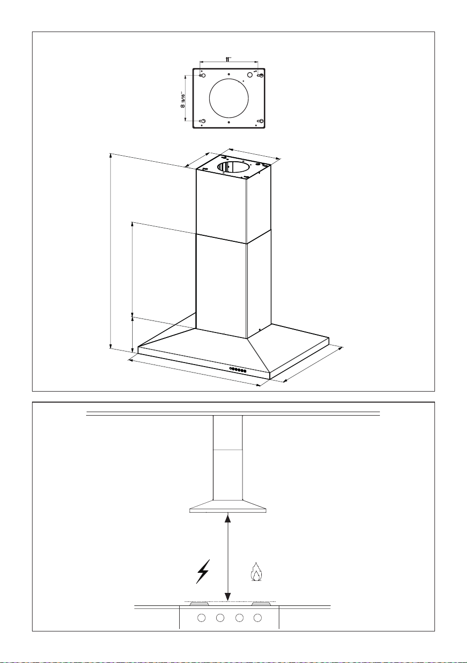
48
Min. 24" Min. 30"
DIMENSIONES DE LA CAMPANA
0,10$;
0,10$;
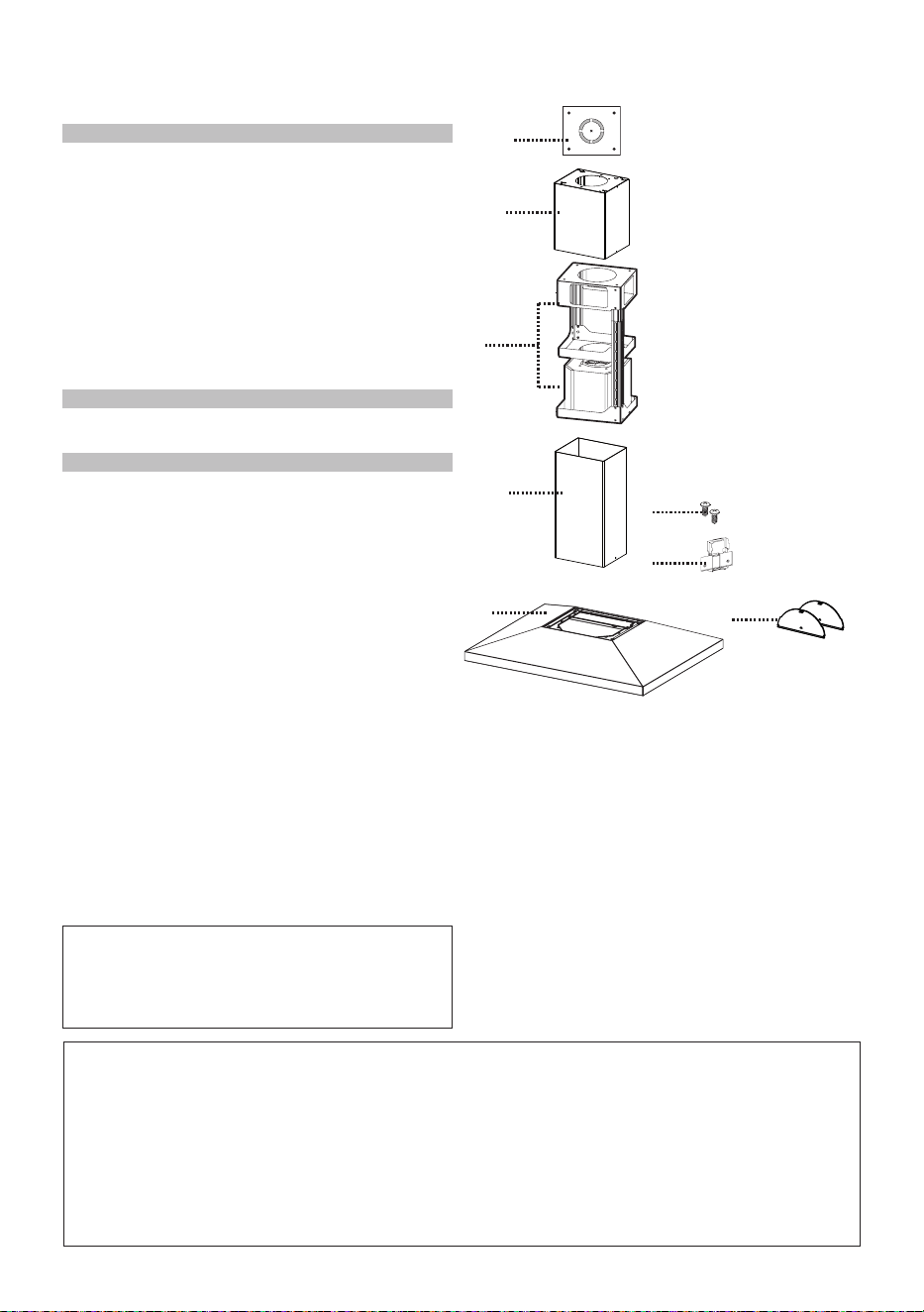
49
PARTES PRINCIPALES
Accesorios disponibles
- Kit de techo alto que sustituye el conducto de humos superior. - sku#HIGH2.
- Kit sin conductos - Incluye un desviador sin conductos, filtros de carbón,
chimenea inferior con rejillas de ventilación - sku # DUCT2
- Accesorio de filtro de carbón activado - sku # FILTER2
- Accesoriode mando remoto inalámbrico - REMORIG
Piezas necesarias
- conducto metálico redondo de 6"
Componentes
Ref. Cdad. Componentes del producto
1 1 Cuerpo de la campana, completo de:
Controles, Luces, Filtros, Ventilador.
2 1 Chimenea telescópica que comprende:
2.1 1 Sección superior
2.2 1 Sección inferior
7.1 1 Bastidor telescópico completo con
extractor, compuesto por:
7.1a 1 Bastidor superior
7.1b 1 Bastidor inferior
10 2 Solapas del regulador
11 1 Cabledejaciónplasticò
Ref. Cdad. Componentes del Instalación
12q 4 Tornillos 1/8" x 1/4"
21 1 Plantilla de perforación
Cdad. Documentación
1 Manual de instrucciones
10
1
2,2
2,1
21
7,1
12q
7,1a
7.1b
11
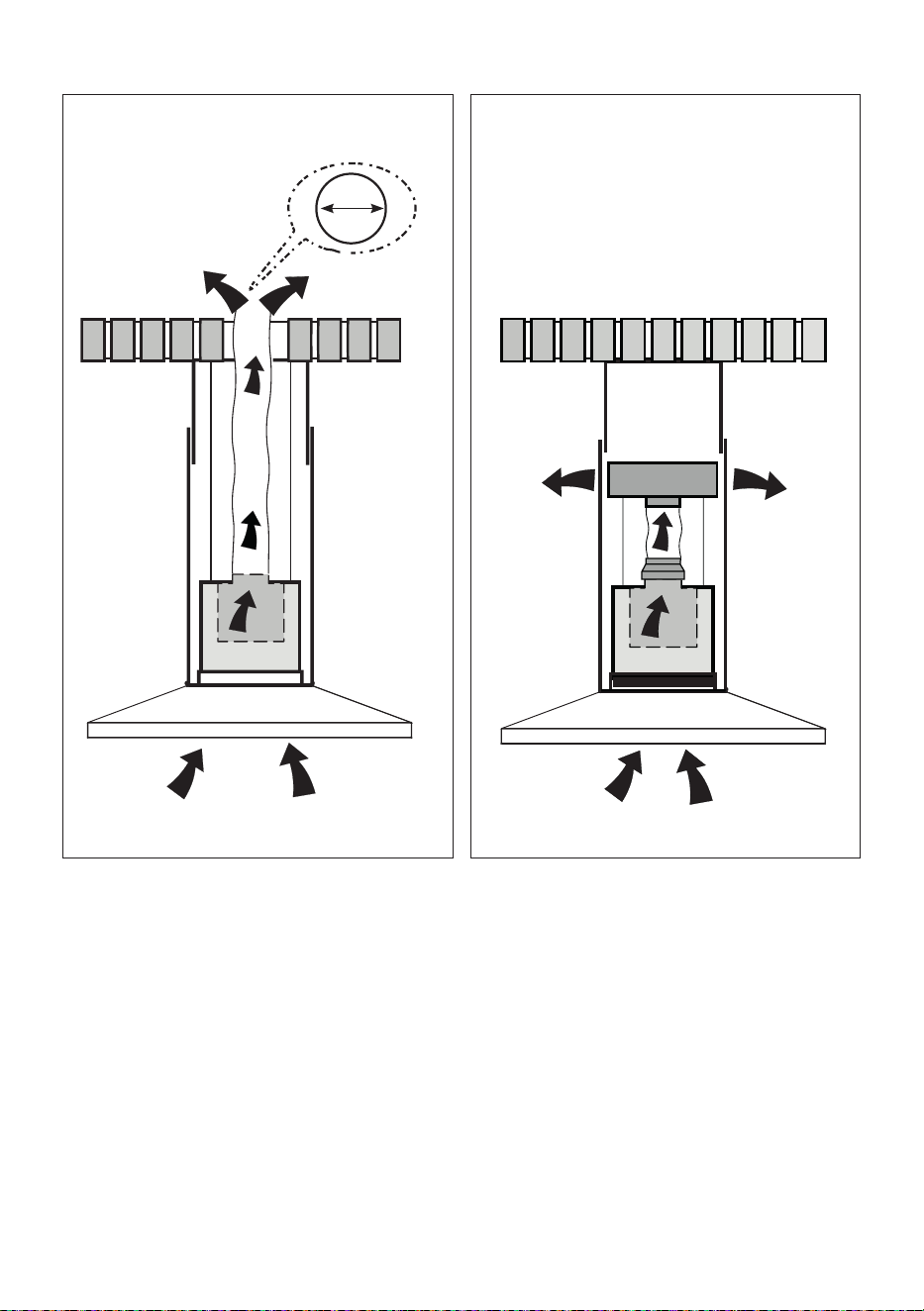
50
Requiere compra de accesorio
de carbón activado
6 "
Elija su método de conducción
Sin conductos - Opción de
recirculación
Instalación de opciones de ventilación
con conductos

51
1
Ponga una cubierta gruesa y protectora
sobre la placa de cocción,
cocina empotrada o encimera para
proteger de daños o suciedad.
Determine y marque claramente con un
lápiz en el techo donde se instalará la
campana.
La plantilla 21 para el montaje del soporte
se suministra en la caja de cartón con el
soporte. Utilice esta plantilla para marcar
agujeros para
el soporte en el techo.
Determine y haga los cortes necesarios
para el conducto. La abertura del conducto
se muestra en la plantilla de montaje. Instale
el conducto antes de montar la campana.
Determine la ubicación correcta del cable
de suministro de energía como se indica
en la plantilla. Use 1 broca de 1 1/4" para hacer
este agujero. Pase el cable de suministro de
energía. Use masilla para sellar alrededor
del agujero.
Un punto de salida para pasar cables
a través de la fuente de alimentación
desde el techo se encuentra en la parte
superior del bastidor. No conecte el cable
de alimentación a la caja de cableado ni
encienda la campana en este momento.
Pase suficiente cable de alimentación desde
el techo para alcanzar la caja de cableado
de la campana.
Ø 10 mm
x4
21
1 1/4"
No haga recortes hasta que haya decidido si esta instalación se realizará con o sin
conducto y luego planifique en consecuencia.
DEBIDO AL TAMAÑO Y AL
PESO DE ESTA CAMPANA,
EL SOPORTE DEBE ESTAR
FIRMEMENTE FIJADO AL
TECHO. Para techos de yeso
o cartón yeso, el soporte
debe estar sujeto a las vigas.
Si esto no es posible, se debe
construir una estructura de
soporte detrás del yeso o el
cartón yeso. El fabricante no
asume ninguna responsabi-
lidad por lesiones o daños
causados por instalaciones
inadecuadas.
ADVERTENCIA
!
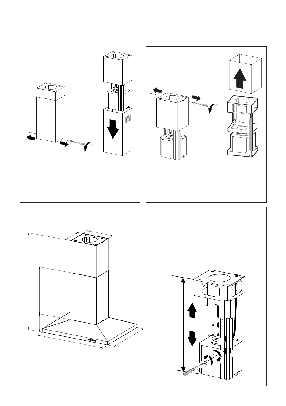
52
2
3
4
1
4
MIN
740
mm
MAX
940
mm
2
3
5
6
0,10$;
Los tubos de la chimenea deben ser retirados antes de instalar la campana
Aojelosdostornillosquesujetanlachimeneainferior
y retírela del bastidor inferior.
Si necesita ajustar la altura del bastidor, proceda de
la siguiente manera:
• Aoje los tornillos métricos que unen las dos
columnas, ubicadas a los lados del bastidor
(1,2,3,4,5,6).
• Ajuste el bastidor a la altura requerida, luego vuelva
a colocar todos los tornillos que retiró como se
indicó anteriormente.
Aojelosdostornillosquesujetanlachimeneasuperior
y retírela del bastidor superior.

53
14. REMOVING THE MIDDLE TRESTLE COMPONENT
NOTE: The chimney structure can reduce down to a 27 " minimum height. To reduce the height,
the middle section of the support structure needs to be removed.
Out of the box, the minimum chimney length is 32 ".
Insure the the installation process outlined in the U&C is followed and there is sufficient stability with the
middle section removed.
5
6
NOTAS : La estructura de la chimenea puede reducir hasta una altura mínima de 27". Para reducir la
altura, la sección central de la estructura de soporte necesita ser retirada.
Fuera de la caja, la longitud mínima de la chimenea es de 32".
AsegúresedequesesigaelprocesodeinstalacióndescritoenU&Cyquehayasucienteestabilidad
con la sección media retirada.
ELIMINACIÓN DEL COMPONENTE TRESTILLO MEDIO
Después de la regulación para el ajuste de altura,
inserte la chimenea superior desde arriba y déjela
libre en el bastidor.
El tubo superior debe estar en su lugar antes
de proceder
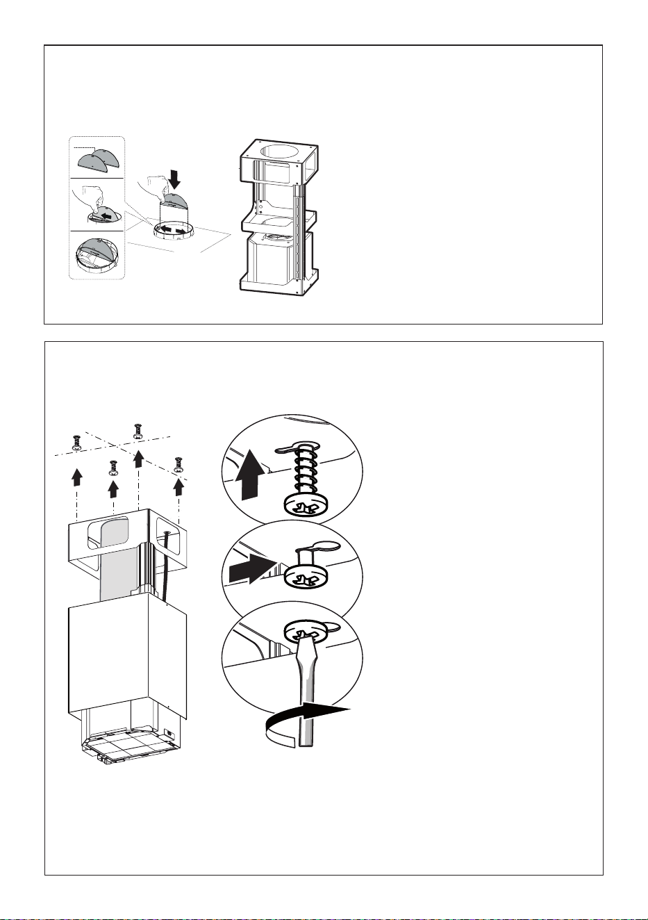
54
7
8
Instale las solapas del amortiguador 10 que se
incluyen con la campana ajustando las lengüetas en
su lugar dentro de la parte superior de la campana
antes de conectar los conductos.
Solo para instalación de ventilación con conductos
Ahora tome sus tornillos para madera o pernos
dependiendodesuconguraciónyatornillelos
cuatroenlosoriciospilotoydeje1/4"delas
cabezas expuestas.
A continuación, instale un dispositivo antitracción
homologado por UL o CSA en la caja de cableado
para que los tornillos puedan apretarse después
dejarelsoportedelachimeneaaltecho.
Ahora levante el soporte de la chimenea hasta
suposiciónnalyalimenteelsuministroeléctrico
a través del dispositivo antitracción.
A continuación, coloque el soporte de la
chimenea de forma que el extremo grande de
las ranuras perforadas quede sobre los tornillos
opernosdejaciónaltecho.Acontinuación,
empuje el soporte de la chimenea para que
los pernos queden en el cuello de las ranuras.
Aprietermementeloscuatrotornillosopernos.
- Los soportes del bastidor deben ser seguros
para soportar el peso de la campana y
cualquier tensión causada por el empuje
lateral ocasional aplicado al dispositivo. Al
terminar, compruebe que la base es estable,
inclusosielbastidorestásujetoaexión.
- En todos los casos en que el techo no sea
losucientementeresistenteenelpuntode
suspensión, el instalador debe proporcionar
el refuerzo utilizando placas adecuadas y
piezas de refuerzo ancladas a las partes
estructuralmente sólidas.
10
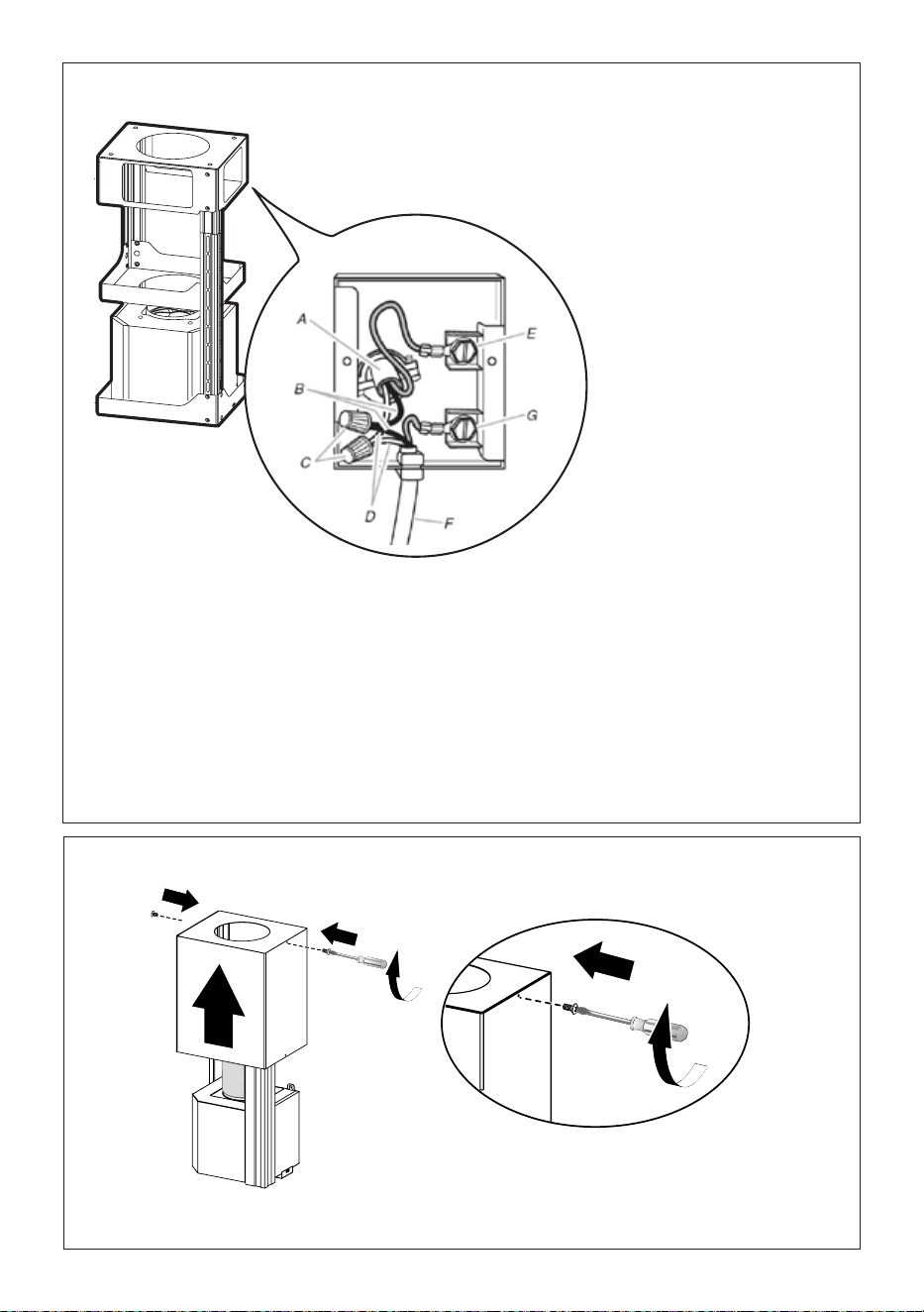
55
Version 02/12 - Page 8
FIGURE 13
MAKE THE ELECTRICAL CONNECTION
Remove the cover from the eld wiring compartment. (SEE
FIGURE 11) DO NOT turn on the power until installation is
complete! Connect the Power Supply Cable to the rangehood.
Connect the Green (Green and Yellow) ground wire under the
Green grounding screw. Attach the White lead of the power
supply to the White lead of the rangehood with a twist-on type
wire connector. Attach the Black lead of the power supply
to the Black lead of the rangehood with a twist-on type wire
connector.
1. The UPPER CHIMNEY
COVER (C in FIGURE 13)
attaches to the top of the
support structure using two
screws provided (G in FIGURE
13). If using the High Ceiling
Chimney Kit, use the UPPER
CHIMNEY COVER supplied
with the kit. Slide up and
attach the UPPER CHIMNEY
COVER.
2. Attach the duct work to the
DAMPER (M in FIGURE 1).
Make sure to seal all joints with
duct tape to prevent leaks.
3. The LOWER CHIMNEY
COVER (B in FIGURE 13)
attaches using two screws
provided (G in FIGURE 13).
Install the LOWER CHIMNEY
COVER by sliding it up over
the support and the UPPER
CHIMNEY COVER.
For ductless installations, line up the DUCTLESS DIVERTER
EXTENSIONS HORIZONTAL (B in FIGURE 12) with the holes
in the LOWER CHIMNEY COVER (D in FIGURE 12) and snap
in the VENT GRIDS (C in FIGURE 12).
INSTALLING THE RANGEHOOD
A. Home power supply cable
B. Black wires
C. UL listed wire connectors
D.White wires
E. Green (or bare) ground wire from home power supply
connected to green ground screw
F. Range hood power supply cable
G.Range hood power supply cable connected to green
ground screw
FIGURE 11
Ductless installations require
a Ductless Conversion
Kit whose components are
pictured in FIGURE 12. Do
not use the DAMPER (M
in FIGURE 1) for ductless
installations. The LOWER
CHIMNEY COVER ( B
in FIGURE 1) should be
discarded and replaced by
the new one with holes from
the Ductless Conversion Kit
(D in FIGURE 12).
As indicated in FIGURE
12, place the DUCTLESS
DIVERTER (A) over the
exhaust opening of the EASY
CUBE (E). Fit the DUCTLESS
DIVERTER EXTENSIONS
HORIZONTAL (B) into the
DIVERTER (A).
FIGURE 12
FOR DUCTLESS INSTALLATIONS
9
10
Instalación de
la conexión de
cableado
Retire la tapa del compartimento
de cableado de campo.
NO encienda la unidad hasta
que se haya completado la
instalación.
Conecte el cable de la fuente de
alimentación a la campana.
Conecte el cable de tierra verde
(verde y amarillo) debajo del tor-
nillo de conexión a tierra verde.
Conecte el cable blanco de la
fuente de alimentación al cable
blanco de la campana con un
conector de cable tipo twist-on.
Conecte el cable negro de la
fuente de alimentación al cable
negro de la campana con un
conector de cable tipo twist-on.
Reemplace la cubierta del compar-
timiento de cableado de campo y
losltrosdegrasa.
A. Cable de la fuente de alimentación doméstica
B. Cables negros
C. Conectores de cable con homologación UL
D. Cables blancos
E. Cable de tierra verde (o decubierto) de la fuente
de alimentación doméstica conectado a un tornillo
de tierra verde
F. Cable de alimentación de la campana extractora
G.Cable de alimentación de la campana extractora
conectado al tornillo de tierra verde
Coloquelapartesuperiordelachimeneayjelapartesuperioralbastidorconlos2tornillosquesehan
quitado anteriormente.
Fijación de los conductos de humos superior e inferior

56
12
11
Version 02/12 - Page 8
FIGURE 13
MAKE THE ELECTRICAL CONNECTION
Remove the cover from the eld wiring compartment. (SEE
FIGURE 11) DO NOT turn on the power until installation is
complete! Connect the Power Supply Cable to the rangehood.
Connect the Green (Green and Yellow) ground wire under the
Green grounding screw. Attach the White lead of the power
supply to the White lead of the rangehood with a twist-on type
wire connector. Attach the Black lead of the power supply
to the Black lead of the rangehood with a twist-on type wire
connector.
1. The UPPER CHIMNEY
COVER (C in FIGURE 13)
attaches to the top of the
support structure using two
screws provided (G in FIGURE
13). If using the High Ceiling
Chimney Kit, use the UPPER
CHIMNEY COVER supplied
with the kit. Slide up and
attach the UPPER CHIMNEY
COVER.
2. Attach the duct work to the
DAMPER (M in FIGURE 1).
Make sure to seal all joints with
duct tape to prevent leaks.
3. The LOWER CHIMNEY
COVER (B in FIGURE 13)
attaches using two screws
provided (G in FIGURE 13).
Install the LOWER CHIMNEY
COVER by sliding it up over
the support and the UPPER
CHIMNEY COVER.
For ductless installations, line up the DUCTLESS DIVERTER
EXTENSIONS HORIZONTAL (B in FIGURE 12) with the holes
in the LOWER CHIMNEY COVER (D in FIGURE 12) and snap
in the VENT GRIDS (C in FIGURE 12).
INSTALLING THE RANGEHOOD
A. Home power supply cable
B. Black wires
C. UL listed wire connectors
D.White wires
E. Green (or bare) ground wire from home power supply
connected to green ground screw
F. Range hood power supply cable
G.Range hood power supply cable connected to green
ground screw
FIGURE 11
Ductless installations require
a Ductless Conversion
Kit whose components are
pictured in FIGURE 12. Do
not use the DAMPER (M
in FIGURE 1) for ductless
installations. The LOWER
CHIMNEY COVER ( B
in FIGURE 1) should be
discarded and replaced by
the new one with holes from
the Ductless Conversion Kit
(D in FIGURE 12).
As indicated in FIGURE
12, place the DUCTLESS
DIVERTER (A) over the
exhaust opening of the EASY
CUBE (E). Fit the DUCTLESS
DIVERTER EXTENSIONS
HORIZONTAL (B) into the
DIVERTER (A).
FIGURE 12
FOR DUCTLESS INSTALLATIONS
Delmismomodo,coloquelaparteinferiordelachimeneayjelaparteinferioralbastidorutilizando
los 2 tornillos retirados previamente.
Solo para instalaciones sin conductos
Las instalaciones sin conductos requieren
un Kit de conversión sin
conductos cuyos componentes se
muestran en la FIGURA 12.
No utilice el REGISTRO para instalaciones
sin conductos. La TAPA DE LA CHIMENEA
INFERIOR debe ser desechada y
reemplazadaporunanuevaconoricios
del Kit de conversión sin
conductos (D en la FIGURA 12).
Como se indica en la FIGURA 12,
coloque el DESVIADOR SIN CONDUCTO
(A) sobre la abertura de escape del EASY
CUBE (E). Ajuste las EXTENSIONES
HORIZONTALES DEL DESVIADOR SIN
CONDUCTO (B) en el DESVIADOR (A).
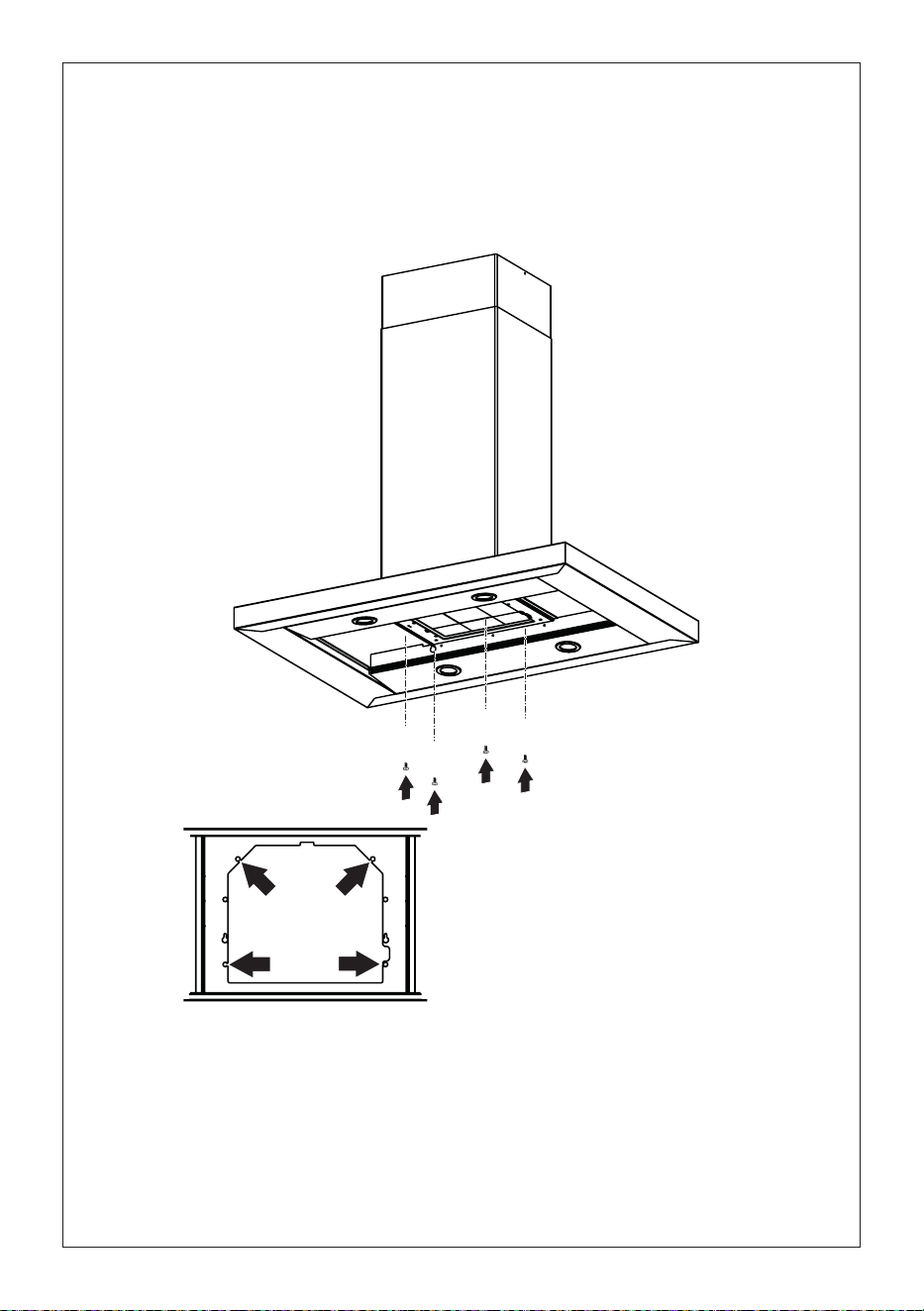
57
13
Retirelosltrosdegrasadelacapotadelacampana.
Retirecualquierltrodecarbónactivado.
Trabajandodesdeabajo,jelacapotadelacampanaalbastidordondeseindica,usandolos4tornillos
12q,luegoaprietetodoslostornillosconrmeza.
Fijación de la capota de la campana
I
I
T[
[

58
1
2
14
a
c
e
b
d
f
Fije el cable
en el espacio
indicado con
cable de fijación
del componente
11, como se
muestra, sin
tensar el cableado,
incluyendo la
conexión de tierra.
Conecte el conector del cable
del cuerpo de la campana al
ventilador como se muestra.
Realice la conexión eléctrica interna
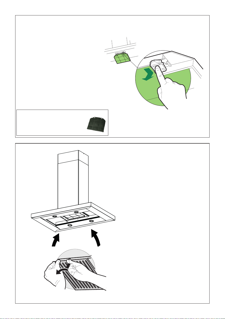
59
15
Attach a
charcoal filter
in the correct
position and
block it by the
fixing hooks
as shown.
Unlock the fixing hooks (towards the back
of the insert hood) to remove.
16
Para la opción de recirculación
sin conducto
Retire los filtros de
grasa metallicos
de la capota de la
campana.
Se requiere accesorio de filtro de
carbón activado - Parte # - FILTER2
(se compra por separado)
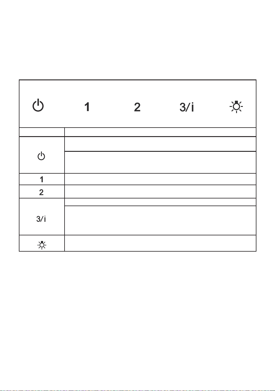
60
INFORMACIÓN DE USO Y CUIDADO
PARAOBTENERMEJORESRESULTADOS
Ponga en marcha la campana extractora varios minutos antes de cocinar
para desarrollar un flujo de aire adecuado. Deje que la campana extracto-
ra funcione durante varios minutos después de terminar de cocinar para
eliminar todo el humo y los olores de la cocina.
NOTA: Si su producto ha tenido un ajuste de CFM, consulte el manual de ajuste de CFM para
obtener más información. Algunas velocidades o funciones del motor pueden verse reducidas.
T1 T2 T3 T4 L
Botón Función
T1 T2 T3 T4 L
Botón de apagado del ventilador: apaga el ventilador. El ventilador se puede
accionar pulsando cualquiera de los botones de ajuste del ventilador.
Mantenga pulsado este botón durante 2 segundos para activar la función de
apagado retardado que mantendrá el ventilador encendido durante 15 minutos y
se apagará automáticamente.
T1 T2 T3 T4 L
Botones de conguración del ventilador: Velocidad baja.
T1 T2 T3 T4 L
Botones de conguración del ventilador: Velocidad media.
T1 T2 T3 T4 L
Botones de conguración del ventilador: Velocidad alta.
Mantenga pulsado el botón durante 2 segundos para activar la VELOCIDAD
INTENSIVA, que está programada para funcionar durante 10 minutos. Transcur-
rido este tiempo, volverá automáticamente a la velocidad jada anteriormente.
Adecuado para hacer frente a niveles máximos de humos de cocción.
T1 T2 T3 T4 L
Botón de luz: Interruptor de encendido/apagado para las luces LED.
Pulse el botón de la LUZ para encenderla y de nuevo para apagarla.

61
Limpieza de los filtros de grasa metálicos
Los filtros se deben limpiar cada 2 meses de
funcionamiento, o con mayor frecuencia con
uso intensivo, y se puede lavar en un lavavajillas.
• Quitar un filtro a la vez, tirar y girar la manilla en
sentido contrario a las agujas del reloj.
• Lave los filtros sin doblarlos y déjelos secar
completamente antes de volver a colocarlos.
(Si la superficie del filtro cambia de color a
medida que pasa el tiempo, esto no tendrá
ningún efecto en la eficacia del filtro).
• Volver a montarla siguiendo la secuencia al
contrario teniendo cuidado de que la manilla
quede hacia la parte exterior.
• Asegúrese de eliminar toda el agua y cualquier
otro líquido antes de volver a instalar los filtros
después de la limpieza.
Reemplazo del filtro de carbón activado
El filtro no es lavable, no puede ser regenerado, y
debe ser reemplazado aproximadamente cada
4 meses de operación, o más frecuentemente
con uso intensivo.
• Retire los filtros de a uno por vez, empujándolos
hacia la parte posterior de la unidad y al mismo
tiempo tirando hacia abajo.
• Retire el filtro de carbón saturado liberando los
ganchos de fijación.
• Coloque el nuevo filtro y ajústelo en su posición
correcta.
• Reemplace, teniendo cuidado de asegurarse
de que la manija mire hacia adelante.
Precaución: "Cuando se usa en el modo de recircu-
lación, para reducir el riesgo de incendio y descar-
ga, utilice únicamente el kit de conversión Modelo
FILTER 2".
Unidad de iluminación
• Las luces LED deben ser reemplaza-
das por el servicio autorizado por la
fábrica Faber.

62
Diagrama de cableado
991.0530.011 H90-503
D00004494_00
991.0530.011 H90-503
D00004494_00
120V
60Hz

63
GARANTÍA
Franke Home Solutions Warranty for Franke and Faber Branded Product
Effective March 1, 2022
In the United States, Canada and Latin America, Franke warrants the Faber branded products from manufacturing defects
in material and workmanship when purchased from a Franke or Faber Authorized Retailer pursuant to product-specific
warranties detailed herein (each, a “Warranty” and collectively, the “Warranties”). The products must be properly installed,
per Franke’s installation instructions, in their original installation, and used in normal indoor residential kitchen
applications. Any products or components which have been modified or altered from their original intended condition will
void the Warranty. The Franke Warranties for Faber branded products are limited to the original purchaser and are non-
transferrable. These Warranties do not include products purchased from non-Authorized Retailers, products that are
obsolete or discontinued, or products that were previous display models. All issues with installed products are considered
warranty claims and not subject to the Return Policy. Franke reserves the right to inspect any Franke / Faber product
reported to be defective pursuant to a Warranty claim and the original installation prior to providing a replacement product
and/or component. All decisions are final. In no situation shall the liability of Franke exceed the amount of the original
purchase price.
The Warranties do not cover, and Franke shall not be liable for, any damage to products or components resulting from
misuse or abuse, accidental damages, normal wear such as scuffs, scratches or finish reduction/fading, improper
installation, abnormal usage, negligence, damage caused by improper maintenance or cleaning. Damage caused by
impurities, corrosive chemicals or acts beyond Franke’s control are not covered by any Warranty. Service calls to correct
the installation of a range hood, instructions on how to operate a range hood, to replace or repair house fuses or to correct
house wiring or plumbing are not covered by any Warranty. Service calls to repair or replace range hood light bulbs, fuses
or filters and these consumable part costs are also excluded from Warranty coverage. Installation not in accordance with
electrical or plumbing codes or Franke / Faber documentation are not covered by any Warranty. Replacement parts or
repair labor costs for units operated outside the United States, Canada or Latin America, including any non-UL or C-UL or
non-NOM approved Franke / Faber range hoods are excluded from Warranty coverage. Expenses for travel and
transportation for service in remote locations and pickup and delivery charges are not covered by any Warranty. Franke /
Faber range hoods should always be serviced in the home in their original installation.
Franke / Faber product replacements do not include liability for project delays. Product replacements are not guaranteed
to be exact replacements. If the original product is not available at the time of the warranty claim, at Franke’s option, the
product replacements will be of similar size, material, and value. Any products or components which have been modified
or altered, from its original intended condition will void the warranty.
The Warranties do not allow recovery of incidental or consequential damages such as loss of use, delay, property
damage or other consequential damage, and Franke accepts no liability for such damages. Each Warranty is limited to
the conditions set forth herein and to the applicable warranty period specified herein and is exclusive. EXCEPT FOR THE
WARRANTIES SET FORTH HEREIN, FRANKE MAKES NO WARRANTY WHATSOEVER WITH RESPECT TO THE
PRODUCTS, INCLUDING, BUT NOT LIMITED TO, (1) ANY WARRANTY OF MERCHANTABILITY, (2) WARRANTY OF
FITNESS FOR A PARTICULAR PURPOSE, (3) WARRANTY OF TITLE, OR (4) WARRANTY AGAINST INFRINGEMENT
OF INTELLECTUAL PROPERTY RIGHTS OF A THIRD PARTY, WHETHER EXPRESS OR IMPLIED BY LAW, COURSE
OF DEALING, COURSE OF PERFORMANCE, USAGE OF TRADE OR OTHERWISE. LEGAL DISCLAIMER PLEASE
READ CAREFULLY. Franke Kitchen Systems LLC provides the above information to you as a public service to our
customers. By accessing and using this information, you agree to the following and to comply with all applicable laws. If
you do not agree with these terms and conditions, do not use this information. While we try to keep the information
current, changes may have occurred since its creation. Contact your Regional Manager or Customer Service to verify
information regarding Franke Kitchen Systems LLC programs and their use by you.
Franke / Faber Range Hood Limited Warranty:
Franke / Faber range hoods are warranted against any defect in materials or workmanship for the original purchaser for a
period of two (2) years from the date of original purchase when used in standard residential indoor applications. This
warranty covers labor and replacement parts. Franke, at its option, may repair or replace the product or components
necessary to restore the product to good working condition.
La garantía de Franke Home Solutions para los productos de las marcas Franke y Faber entra en vigor el 1 de marzo de 2022
En Estados Unidos, Canadá y América Latina, Franke garantiza los productos de la marca Faber contra defectos de fabricación
en materiales y mano de obra cuando se compran a un minorista autorizado de Franke o Faber de acuerdo con las garantías
específicas del producto que se detallan en este documento (cada una, una "Garantía" y colectivamente, las "Garantías"). Los
productos deben ser instalados correctamente, según las instrucciones de instalación de Franke, en su instalación original,
y utilizados en aplicaciones normales de cocina residencial en interiores. Cualquier producto o componente que haya sido
modificado o alterado de su condición original anulará la garantía. Las garantías de Franke para los productos de la marca Faber
están limitadas al comprador original y no son transferibles. Estas garantías no incluyen los productos comprados a minoristas no
autorizados, los productos obsoletos o descatalogados, ni los productos que eran modelos de exposición anteriores. Todos los
problemas con los productos instalados se consideran reclamaciones de garantía y no están sujetos a la política de devoluciones.
Franke se reserva el derecho de inspeccionar cualquier producto Franke / Faber reportado como defectuoso en virtud de una
reclamación de garantía y la instalación original antes de proporcionar un producto y/o componente de reemplazo. Todas las
decisiones son definitivas. En ningún caso la responsabilidad de Franke superará el importe del precio de compra original.
Las garantías no cubren, y Franke no será responsable, de ningún daño a los productos o componentes derivado de un mal uso
o abuso, daños accidentales, desgaste normal como rozaduras, arañazos o reducción/descoloramiento del acabado, instalación
incorrecta, uso anormal, negligencia, daños causados por un mantenimiento o limpieza inadecuados. Los daños causados por
impurezas, productos químicos corrosivos o actos fuera del control de Franke no están cubiertos por ninguna garantía. Las
llamadas de servicio para corregir la instalación de una campana extractora, las instrucciones sobre el funcionamiento de una
campana extractora, para sustituir o reparar los fusibles de la casa o para corregir el cableado o la fontanería de la casa no están
cubiertas por ninguna Garantía. Las llamadas de servicio para reparar o sustituir las bombillas, fusibles o filtros de la campana
extractora, así como los costes de estas piezas consumibles, también están excluidos de la cobertura de la garantía. La instalación
que no esté de acuerdo con los códigos eléctricos o de fontanería o con la documentación de Franke / Faber no está cubierta
por ninguna garantía. Los costes de las piezas de repuesto o de la mano de obra de reparación de las unidades utilizadas fuera
de los Estados Unidos, Canadá o América Latina, incluidas las campanas extractoras de cocina Franke / Faber no aprobadas por
la norma UL o C-UL, están excluidos de la cobertura de la garantía. Los gastos de viaje y transporte para el servicio en lugares
remotos y los gastos de recogida y entrega no están cubiertos por ninguna Garantía. Las campanas extractoras Franke / Faber
siempre deben ser revisadas en el hogar en su instalación original.
Las sustituciones de productos Franke / Faber no incluyen la responsabilidad por los retrasos del proyecto. No se garantiza que
las sustituciones de los productos sean exactas. Si el producto original no está disponible en el momento de la reclamación de
la garantía, a opción de Franke, los reemplazos del producto serán de tamaño, material y valor similares. Cualquier producto o
componente que haya sido modificado o alterado de su condición original anulará la garantía.
Las garantías no permiten la recuperación de los daños incidentales o indirectos, como la pérdida de uso, el retraso, los daños a la
propiedad u otros daños indirectos, y Franke no acepta ninguna responsabilidad por tales daños. Cada Garantía está limitada a las
condiciones establecidas en el presente documento y al período de garantía aplicable especificado en el mismo y es exclusiva. A
EXCEPCIÓN DE LAS GARANTÍAS ESTABLECIDAS EN ESTE DOCUMENTO, FRANKE NO OFRECE NINGUNA GARANTÍA CON
RESPECTO A LOS PRODUCTOS, INCLUYENDO, PERO NO LIMITADO A, (1) CUALQUIER GARANTÍA DE COMERCIALIZACIÓN,
(2) LA GARANTÍA DE IDONEIDAD PARA UN PROPÓSITO PARTICULAR, (3) LA GARANTÍA DE TÍTULO, O (4) LA GARANTÍA
CONTRA LA VIOLACIÓN DE LOS DERECHOS DE PROPIEDAD INTELECTUAL DE UN TERCERO, YA SEA EXPRESA O
IMPLÍCITA POR LA LEY, EL DESARROLLO DE LOS NEGOCIOS, EL DESARROLLO DE LA EJECUCIÓN, EL USO DEL COMERCIO
O DE OTRA MANERA. AVISO LEGAL POR FAVOR
LEA ATENTAMENTE. Franke Kitchen Systems LLC le proporciona la información anterior como un servicio público a nuestros
clientes. Al acceder y utilizar esta información, usted acepta lo siguiente y el cumplimiento de todas las leyes aplicables. Si no está
de acuerdo con estas condiciones, no utilice esta información. Aunque intentamos mantener la información actualizada, pueden
haberse producido cambios desde su creación. Póngase en contacto con su gerente regional o con el servicio de atención al
cliente para verificar la información relativa a los programas de Franke Kitchen Systems LLC y su uso.
Garantía limitada de la campana extractora Franke / Faber:
Las campanas extractoras de Franke / Faber están garantizadas contra cualquier defecto de materiales o mano de obra
para el comprador original durante un período de dos (2) años a partir de la fecha de compra original cuando se utilizan en
aplicaciones residenciales estándar de interior. Esta garantía cubre la mano de obra y las piezas de recambio. Franke, a su elección,
puede reparar o sustituir el producto o los componentes necesarios para restablecer el producto en buenas condiciones de
funcionamiento.

64
Franke Home Solutions Warranty for Franke and Faber Branded Product
Effective March 1, 2022
In the United States, Canada and Latin America, Franke warrants the Faber branded products from manufacturing defects
in material and workmanship when purchased from a Franke or Faber Authorized Retailer pursuant to product-specific
warranties detailed herein (each, a “Warranty” and collectively, the “Warranties”). The products must be properly installed,
per Franke’s installation instructions, in their original installation, and used in normal indoor residential kitchen
applications. Any products or components which have been modified or altered from their original intended condition will
void the Warranty. The Franke Warranties for Faber branded products are limited to the original purchaser and are non-
transferrable. These Warranties do not include products purchased from non-Authorized Retailers, products that are
obsolete or discontinued, or products that were previous display models. All issues with installed products are considered
warranty claims and not subject to the Return Policy. Franke reserves the right to inspect any Franke / Faber product
reported to be defective pursuant to a Warranty claim and the original installation prior to providing a replacement product
and/or component. All decisions are final. In no situation shall the liability of Franke exceed the amount of the original
purchase price.
The Warranties do not cover, and Franke shall not be liable for, any damage to products or components resulting from
misuse or abuse, accidental damages, normal wear such as scuffs, scratches or finish reduction/fading, improper
installation, abnormal usage, negligence, damage caused by improper maintenance or cleaning. Damage caused by
impurities, corrosive chemicals or acts beyond Franke’s control are not covered by any Warranty. Service calls to correct
the installation of a range hood, instructions on how to operate a range hood, to replace or repair house fuses or to correct
house wiring or plumbing are not covered by any Warranty. Service calls to repair or replace range hood light bulbs, fuses
or filters and these consumable part costs are also excluded from Warranty coverage. Installation not in accordance with
electrical or plumbing codes or Franke / Faber documentation are not covered by any Warranty. Replacement parts or
repair labor costs for units operated outside the United States, Canada or Latin America, including any non-UL or C-UL or
non-NOM approved Franke / Faber range hoods are excluded from Warranty coverage. Expenses for travel and
transportation for service in remote locations and pickup and delivery charges are not covered by any Warranty. Franke /
Faber range hoods should always be serviced in the home in their original installation.
Franke / Faber product replacements do not include liability for project delays. Product replacements are not guaranteed
to be exact replacements. If the original product is not available at the time of the warranty claim, at Franke’s option, the
product replacements will be of similar size, material, and value. Any products or components which have been modified
or altered, from its original intended condition will void the warranty.
The Warranties do not allow recovery of incidental or consequential damages such as loss of use, delay, property
damage or other consequential damage, and Franke accepts no liability for such damages. Each Warranty is limited to
the conditions set forth herein and to the applicable warranty period specified herein and is exclusive. EXCEPT FOR THE
WARRANTIES SET FORTH HEREIN, FRANKE MAKES NO WARRANTY WHATSOEVER WITH RESPECT TO THE
PRODUCTS, INCLUDING, BUT NOT LIMITED TO, (1) ANY WARRANTY OF MERCHANTABILITY, (2) WARRANTY OF
FITNESS FOR A PARTICULAR PURPOSE, (3) WARRANTY OF TITLE, OR (4) WARRANTY AGAINST INFRINGEMENT
OF INTELLECTUAL PROPERTY RIGHTS OF A THIRD PARTY, WHETHER EXPRESS OR IMPLIED BY LAW, COURSE
OF DEALING, COURSE OF PERFORMANCE, USAGE OF TRADE OR OTHERWISE. LEGAL DISCLAIMER PLEASE
READ CAREFULLY. Franke Kitchen Systems LLC provides the above information to you as a public service to our
customers. By accessing and using this information, you agree to the following and to comply with all applicable laws. If
you do not agree with these terms and conditions, do not use this information. While we try to keep the information
current, changes may have occurred since its creation. Contact your Regional Manager or Customer Service to verify
information regarding Franke Kitchen Systems LLC programs and their use by you.
Franke / Faber Range Hood Limited Warranty:
Franke / Faber range hoods are warranted against any defect in materials or workmanship for the original purchaser for a
period of two (2) years from the date of original purchase when used in standard residential indoor applications. This
warranty covers labor and replacement parts. Franke, at its option, may repair or replace the product or components
necessary to restore the product to good working condition.
Esta garantía sustituye a todas las demás garantías, expresas o implícitas. Ningún empleado, representante
de ventas de campo o distribuidor está autorizado a dar ninguna garantía en nombre de Franke Kitchen
Systems, LLC
Para reclamar la garantía de un producto instalado, póngase en contacto con Franke a través de la
información de contacto proporcionada a continuación. Todos los reclamos de garantía deben incluir lo
siguiente para su procesamiento:
1. Prueba de compra en un distribuidor autorizado de Franke o Faber
2. Nombre del comprador original, dirección (incluyendo ciudad, estado y código postal), dirección de
correo electrónico y número de teléfono
3. Modelo y número de serie de Franke / Faber
4. Fecha de instalación
5. Descripción del defecto
6. Fotos del defecto
En América del Norte y América Latina:
Soluciones para el hogar Franke
A la atención de: Departamento de Garantía
800 Aviation Parkway
Smyrna, TN 37167
HS-Warranty.US@Franke.com
Persona jurídica:
Franke Kitchen Systems LLC

65

66

67

991.0716.785_03 - 240612 - D000000009713_02
