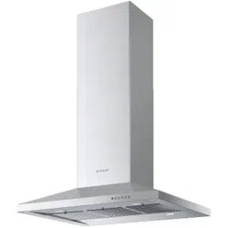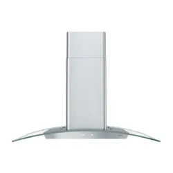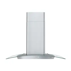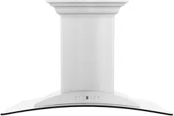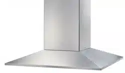
DAMAIS36SSV
DAMAIS42SSV
DAMA ISOLA
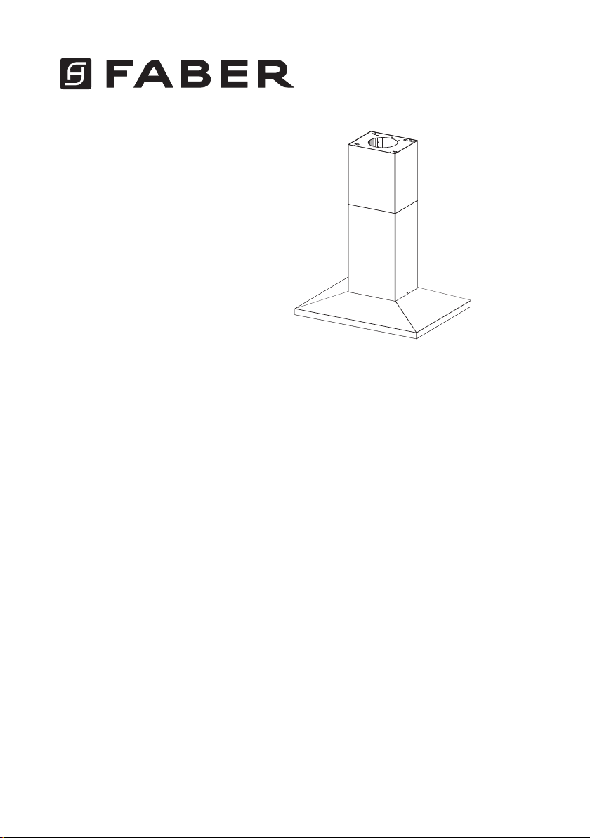
Installation Instructions
Use and Care Information
Instructions d'installation
Utilisez et d'entretien
Instrucciones de instalación
Información de uso y cuidado

2
READ AND SAVE THESE INSTRUCTIONS BEFORE YOU START
INSTALLING THIS RANGEHOOD
WARNING: - TO REDUCE THE RISK OF A RANGE TOP GREASE FIRE:
a) Never leave surface units unattended at high settings. Boilovers cause smoking and
greasy spillovers that may ignite. Heat oils slowly on low or medium setting.
b)AlwaysturnhoodONwhencookingathighheatorwhenambeingfood(i.e.Crepes
Suzette, Cherries Jubilee, Peppercorn Beef Flambé).
c) Clean ventilating fans frequently. Grease should not be allowed to accumulate on fan
orlter.
d) Use proper pan size. Always use cookware appropriate for the size of the surface element.
WARNING: - TO REDUCE THE RISK OF INJURY TO PERSONS IN THE EVENT OF A
RANGE TOP GREASE FIRE, OBSERVE THE FOLLOWING*:
a)SMOTHERFLAMESwithaclose-ttinglid,cookiesheet,ormetaltray,thenturnofftheburner.
BECAREFULTOPREVENTBURNS.IftheamesdonotgooutimmediatelyEVACUATE
AND CALL THE FIRE DEPARTMENT.
b) NEVER PICK UP A FLAMING PAN - You may be burned.
c) DO NOT USE WATER, including wet dishcloths or towels - a violent steam explosion will
result.
d) Use an extinguisher ONLY if:
1. You know you have a Class ABC extinguisher, and you already know how to operate it.
2. Thereissmallandcontainedintheareawhereitstarted.
3. Theredepartmentisbeingcalled.
4. Youcanghttherewithyourbacktoanexit.
* Based on "Kitchen Firesafety Tips" published by NFPA
WARNING - TO REDUCE THE RISK OF FIRE OR ELECTRIC SHOCK, do not use this
fan with any solid-state speed control device.
WARNING - TO REDUCE THE RISK OF FIRE, ELECTRICAL SHOCK, OR INJURY TO
PERSONS, OBSERVE THE FOLLOWING:
1. Use this unit only in the manner intended by the manufacturer. If you have any
questions, contact the manufacturer.
2. Before servicing or cleaning unit, switch power off at service panel and lock the
service disconnecting means to prevent power from being switched on acciden-
tally. When the service disconnecting means cannot be locked, securely fasten a
prominent warning device, such as a tag, to the service panel.
CAUTION: For General Ventilating Use Only. Do Not Use To Exhaust Hazardous or
Explosive Materials and Vapors.
WARNING - TO REDUCE THE RISK OF FIRE, ELECTRICAL SHOCK, OR INJURY TO
PERSONS, OBSERVE THE FOLLOWING:
1. InstallationWorkAndElectricalWiringMustBeDoneByQualiedPerson(s)InAccor-
dance With All Applicable Codes And Standards, Including Fire-Rated Construction.
2. Sufcientairisneededforpropercombustionandexhaustingofgasesthrough
theue(chimney)offuelburningequipmenttopreventbackdrafting.Followthe
heating equipment manufacturer's guideline and safety standards such as those
publishedbytheNationalFireProtectionAssociation(NFPA), and the American
SocietyforHeating,RefrigerationandAirConditioningEngineers(ASHRAE),and
the local code authorities.
3
3. When cutting or drilling into wall or ceiling, do not damage electrical wiring and
other hidden utilities.
4. Ducted fans must always be vented to the outdoors.
ALL WALL AND FLOOR OPENINGS WHERE THE RANGEHOOD IS INSTALLED MUST
BE SEALED.
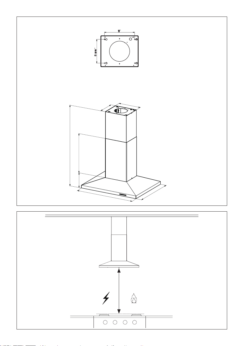
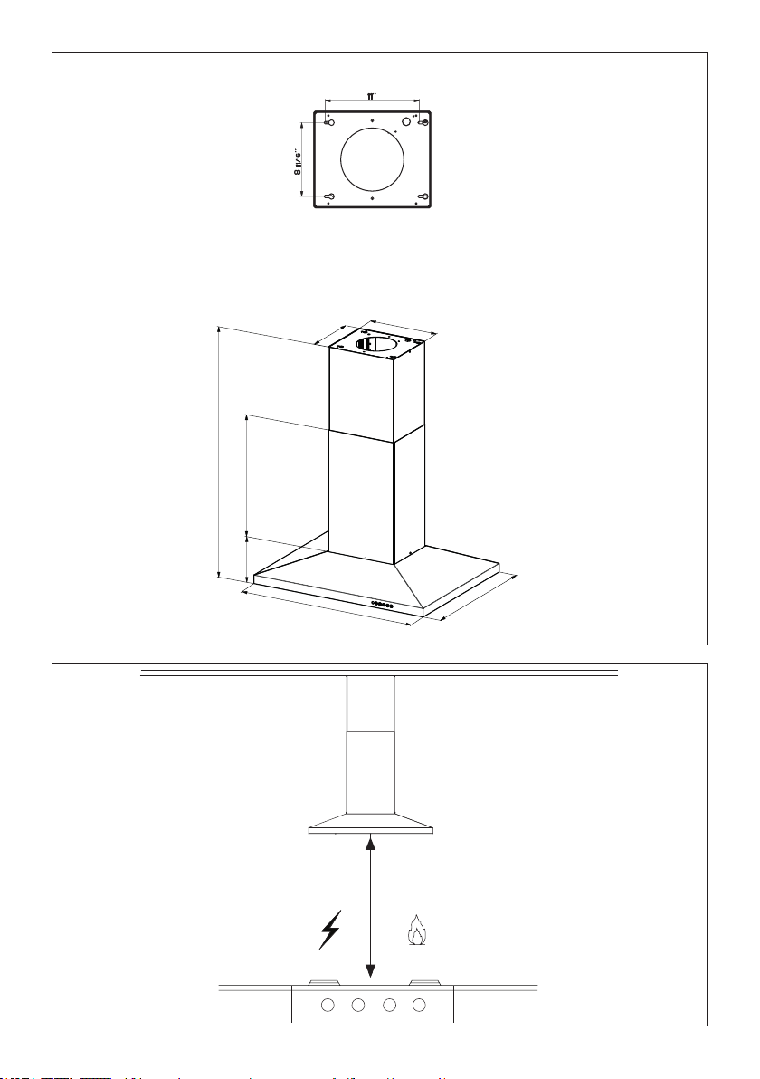
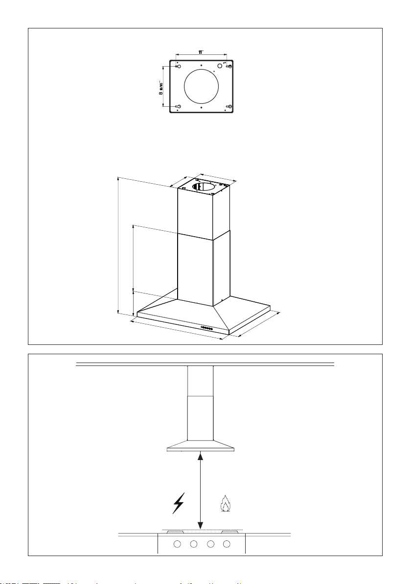
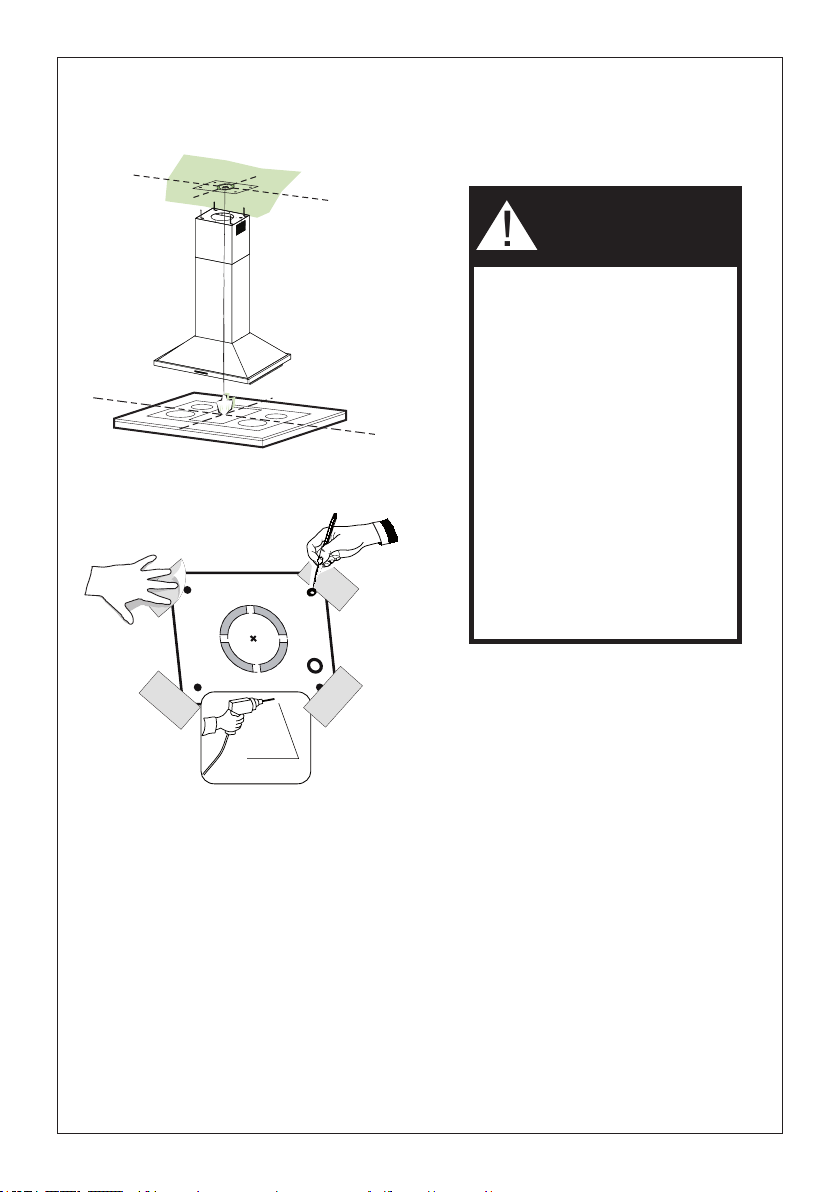
This rangehood requires at least 24" of clearance between the bottom of the rangehood
and the cooking surface or countertop. This hood has been approved by UL at this distance
from the cooktop.
This minimum clearance may be higher depending on local building codes. For gas cooktops and
combination ranges, a minimum of 30" is recommended and may be required.
Overhead cabinets on both sides of this unit must be a minimum of 18" above the cooking surface
or countertop. Consult the cooktop or range installation instructions given by the manufacturer
before making any cutouts.
MOBILE HOME INSTALLATION The installation of this rangehood must conform to the Manufactured
Home Construction and Safety Standards, Title 24 CFR, Part 3280 (formerly Federal Standard
for Mobile Home Construction and Safety, Title 24, HUD, Part 280). See Electrical Requirements.
• Venting system MUST terminate outside the home.
• DO NOT terminate the ductwork in an attic or other enclosed space.
• DO NOT use 4" laundry-type wall caps.
• Flexible-type ductwork is not recommended.
• DO NOT obstruct the ow of combustion and ventilation air.
• Failure to follow venting requirements may result in a re.
WARNING
!
VENTING REQUIREMENTS
Determine which venting method is best for your application. Ductwork can extend either through the
wall or the roof.
The length of the ductwork and the number of elbows should be kept to a minimum to provide efcient
performance. The size of the ductwork should be uniform. Do not install two elbows together. Use
duct tape to seal all joints in the ductwork system. Use caulking to seal exterior wall or oor opening
around the cap.
Flexible ductwork is not recommended. Flexible ductwork creates back pressure and air turbulence
that greatly reduces performance.
Make sure there is proper clearance within the wall or oor for exhaust duct before making cutouts.
Do not cut a joist or stud unless absolutely necessary. If a joist or stud must be cut, then a supporting
frame must be constructed.
WARNING - To Reduce The Risk Of Fire, Use Only Metal Ductwork.
CAUTION-Toreduceriskofreandtoproperlyexhaustair,besuretoductairoutside–Do
not vent exhaust air into spaces within walls or ceilings or into attics, crawl spaces, or garages.
4
ELECTRICAL REQUIREMENTS
A 120 volt, 60 Hz AC-only electrical supply is required on a separate 15 amp fused circuit. A time-delay
fuse or circuit breaker is recommended. The fuse must be sized per local codes in accordance with
the electrical rating of this unit as specied on the serial/rating plate located inside the unit near the eld
wiring compartment.
ELECTRICAL INSTALLATION WITH WIRING BOX
THIS UNIT MUST BE CONNECTED WITH COPPER WIRE ONLY. Wire sizes must conform to the
requirements of the National Electrical Code, ANSI/NFPA 70 - latest edition, and all local codes and
ordinances. Wire size and connections must conform with the rating of the appliance. Copies of the
standard listed above may be obtained from:
National Fire Protection Association
Batterymarch Park
Quincy, Massachusetts 02269
This appliance should be connected directly to the fused disconnect (or circuit breaker) through
exible, armored or nonmetallic sheathed copper cable. Allow some slack in the cable so the
appliance can be moved if servicing is ever necessary. A UL Listed, 1/2" conduit connector must
be provided at each end of the power supply cable (at the appliance and at the junction box).
When making the electrical connection, cut a 1 1/4" hole in the wall. A hole cut through wood
must be sanded until smooth. A hole through metal must have a grommet.
• Electrical ground is required on this rangehood.
• If cold water pipe is interrupted by plastic, nonmetallic gaskets or other materials, DO
NOT use for grounding.
• DO NOT ground to a gas pipe.
• DO NOT have a fuse in the neutral or grounding circuit. A fuse in the neutral or
grounding circuit could result in electrical shock.
• Check with a qualied electrician if you are in doubt as to whether the rangehood is
properly grounded.
• Failure to follow electrical requirements may result in a re.
WARNING
!
StateofCaliforniaProposition65Warning(USonly)
WARNING
This product contains chemicals known to the State of California to cause cancer and birth
defects or other reproductive harm.
For more information go to www.P65Warnings.ca.gov
5
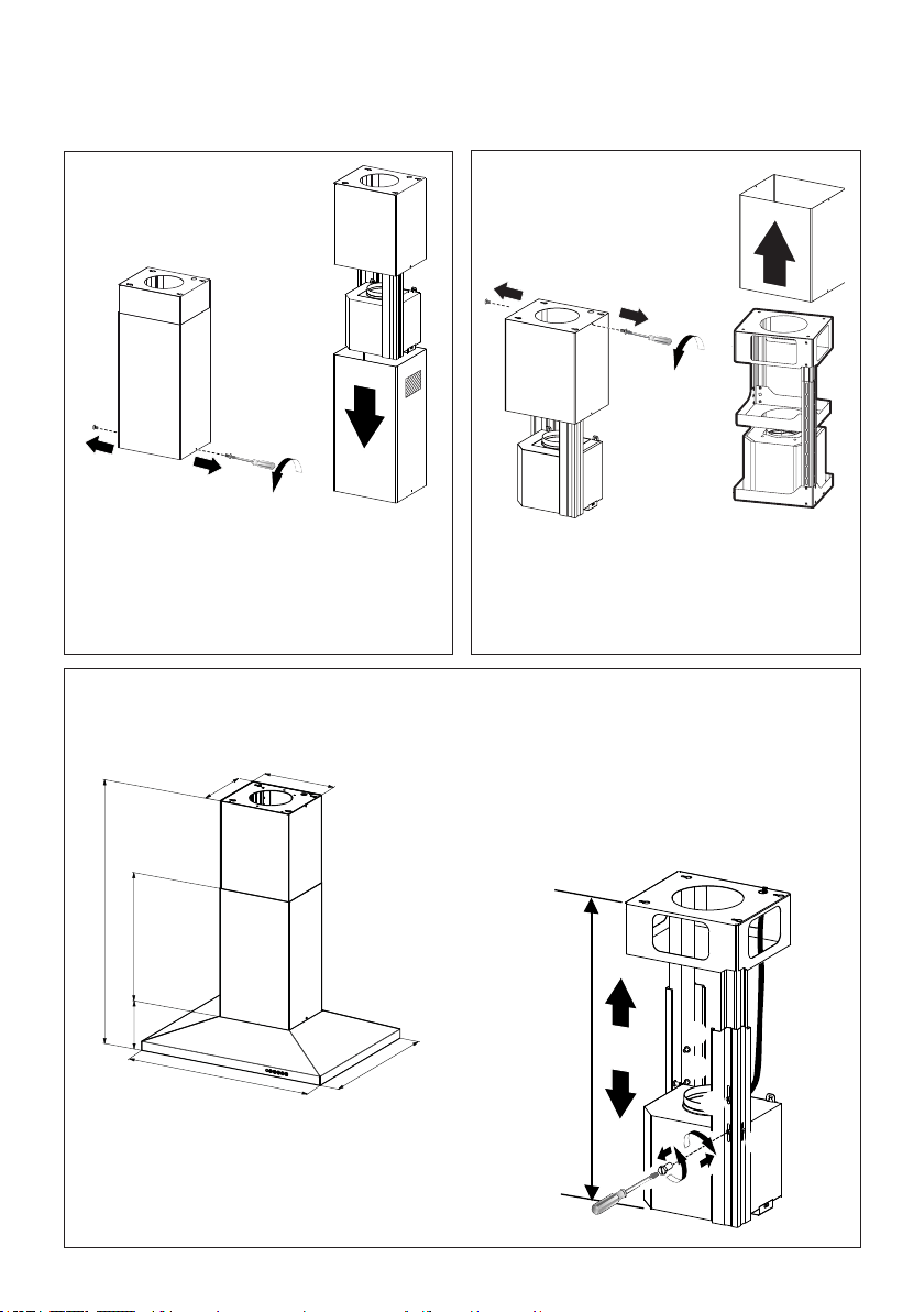
RANGEHOOD DIMENSIONS
0,10$;
Min. 24" Min. 30"
6
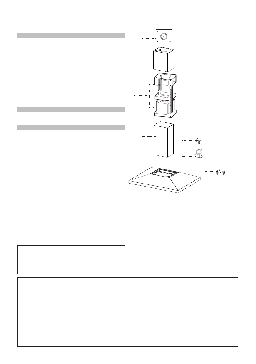
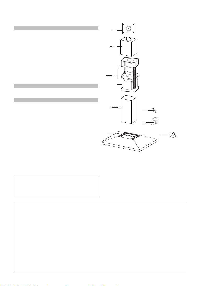
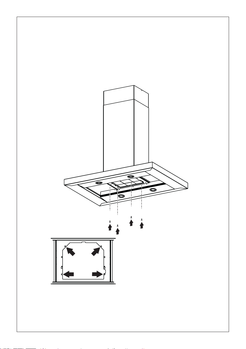
MAIN PARTS
Available Accessories
-HighCeilingKitthatreplacestheupperue.-sku#HIGH2.
-DuctlessKit-IncludesDuctlessDiverter,CharcoalFilters,Lowerchimneywithvent
grates-sku#DUCT2
-ActivatedCharcoalFilterAccessory-sku#FILTER2
- Wireless RemoteControlAccessory-REMCTRL2
Parts needed
-6"RoundMetalductwork
Components
Ref. Qty. Product Components
1 1 Hood Body, complete with: Con-
trols, Light, Filters, Blower.
2 1 Telescopic Chimney comprising:
2.1 1 Upper Section
2.2 1 Lower Section
7.1 1 Telescopic frame complete with
extractor, consisting of:
7.1a 1 Upper frame
7.1b 1 Lower frame
10 1 Damper ø 5 7/8"
11 1 Plasticxingcable
Ref. Qty. Installation Components
12q 4 Screws 1/8" x 1/4"
21 1 Drilling template
Qty. Documentation
1 Instruction Manual
10
1
2.2
2.1
21
7.1
12q
7.1a
7.1b
11
7
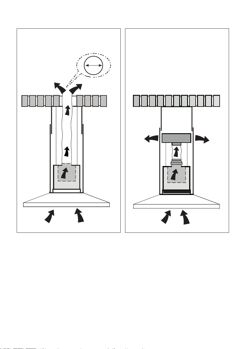
Choose your ducting method
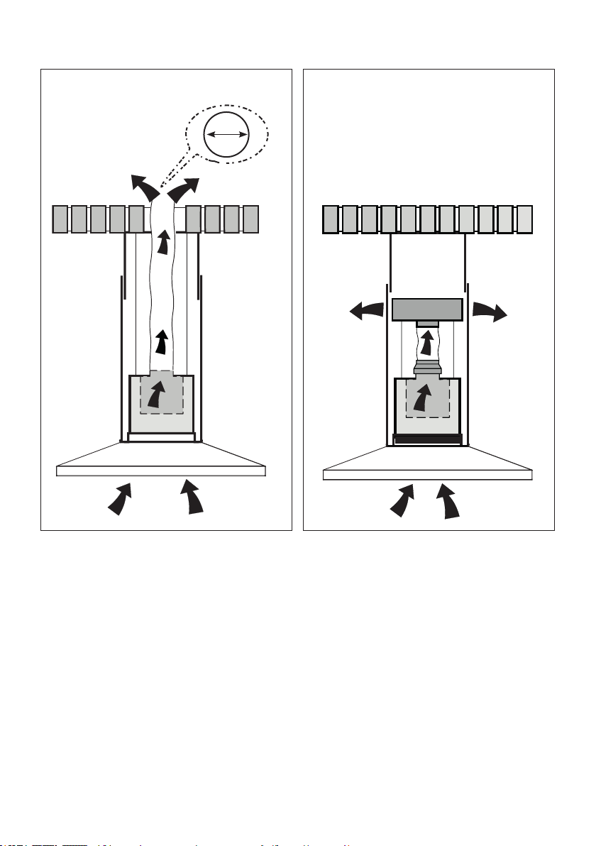
Non Ducted - RecirculationDucted Venting Installation
RequiresDuctlessAccessoryKit
(purchasedseparately)
6 "
8
1
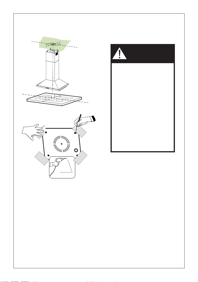
Putathick,protectivecoveringovercooktop,
set-in range or countertop to protect from
damageordirt.
Determineandclearlymarkwithapencilonthe
ceilingwheretherangehoodwillbeinstalled.
A template 21 for mounting the support is
suppliedin the cartonwith the support.Use
thistemplatetomarkholesfor
supportontheceiling.
Determineand make necessary cutsforthe
ductwork.Theductopeningisshownonthe
mountingtemplate.Install
ductworkbeforemountingthehood.
Determine the proper location for the Power
Supply Cable as indicated on the template.
Use a 1 1/4" Drill Bit to make this hole. Run
thePowerSupplyCable.Usecaulkingtoseal
aroundthehole.
A knockout for threading through the Power
Supply from the ceilingis located on the top
oftheframe.DonotconnectthePowerCable
totheWiringBoxorpowerupthehoodatthis
time.Runenoughpowercablefromtheceiling
toreachthewiringboxonthehood.
Ø 10 mm
x4
21
1 1/4"
Donotmakeanycutoutsuntilyouhavedecidedwhetherthisinstallationwillbeductedor
non-ductandthenplanaccordingly.
DUE TO THE SIZE AND
WEIGHT OF THIS RANGE-
HOOD, THE SUPPORT MUST
BE FIRMLY ATTACHED TO
THE CEILING. For plaster or
sheet rock ceiling, the support
must be attached to the joists.
If this is not possible, a support
structure must be built behind
the plaster or sheet rock. The
manufacturer assumes no re-
sponsibility forinjury or damage
caused by improper installa-
tions.
WARNING
!
9
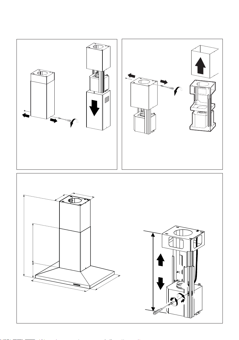
Chimney Flues Must Be Removed Before Installing the Hood
2
3
4
Loosen the two screws fastening the lower chimney
and remove this from the lower frame.
If you need to adjust the height of the frame,
proceed as follows:
• Unfasten the metric screws joining the two
columns, located at the sides of the frame
(1,2,3,4,5,6).
• Adjust the frame to the height required, then
retallthescrewsremovedasabove.
Loosen the two screws fastening the upper chimney
and remove this from the upper frame.
1
4
MIN
740
mm
MAX
940
mm
2
3
5
6
0,10$;

10
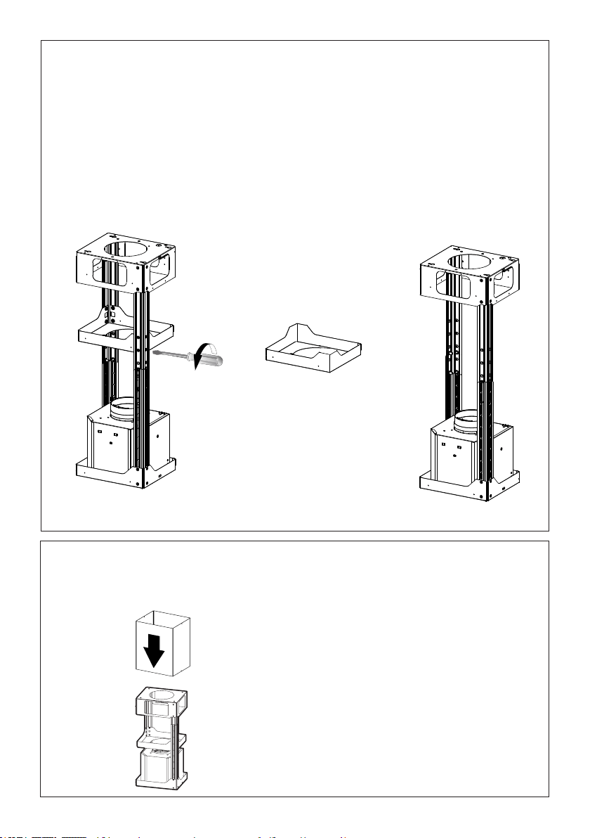
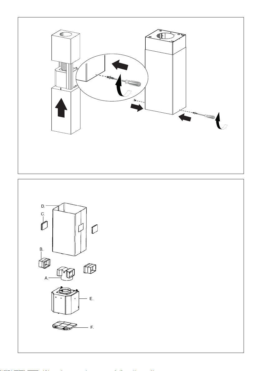
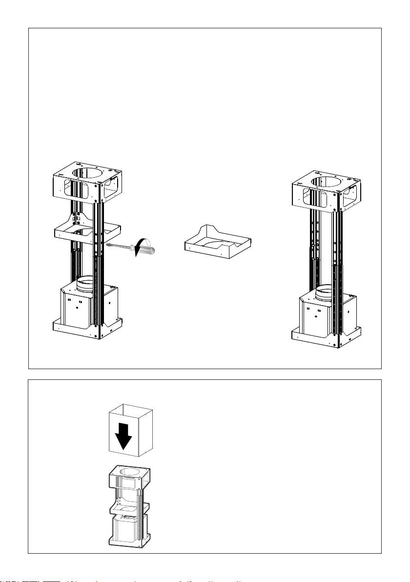
14. REMOVING THE MIDDLE TRESTLE COMPONENT
NOTE: The chimney structure can reduce down to a 27 " minimum height. To reduce the height,
the middle section of the support structure needs to be removed.
Out of the box, the minimum chimney length is 32 ".
Insure the the installation process outlined in the U&C is followed and there is sufficient stability with the
middle section removed.
5
NOTE: The chimney structure can reduce down to a 27 " minimum height. To reduce the height,
the middle section of the support structure needs to be removed.
Out of the box, the minimum chimney length is 32 ".
InsurethetheinstallationprocessoutlinedintheU&Cisfollowedandthereissufcientstabilitywiththe
middle section removed.
REMOVING THE MIDDLE TRESTLE COMPONENT
6
After the regulation for height adjustment, insert
the upper chimney stack from above, and leave it
running free on the frame.
Upper Flue Must Be In Place Before Proceeding
11
7
Install Damper that is included with the Hood before
connecting to the ductwork.
Only for Ducted Venting Installation
8
Now take either your wood screws or bolts
depending on your set-up and screw all four
into the pilot holes and leave 1/4" of the
heads exposed.
Next install a UL or CSA listed strain relief
in the wiring box so that the screws can
be tightened after the chimney support is
attached to the ceiling.
Now lift thechimney support into it's nal
position and feed the electrical supply through
the strain relief.
Next position the chimney support so that
the large end of the keyhole slots are over
the ceiling attachment screws or bolts. Then
push the chimney support so that the bolts
are in the neck of the slots. Tighten all four
screws or bolts securely.
• The frame mountings must be secure to
withstand the weight of the hood and any
stresses caused by the occasional side
thrust applied to the device. On completion,
check that the base is stable, even if the
frame is subjected to bending.
• In all cases where the ceiling is not
strong enough at the suspension point,
the installer must provide strengthening
using suitable plates and backing pieces
anchored to the structurally sound parts.
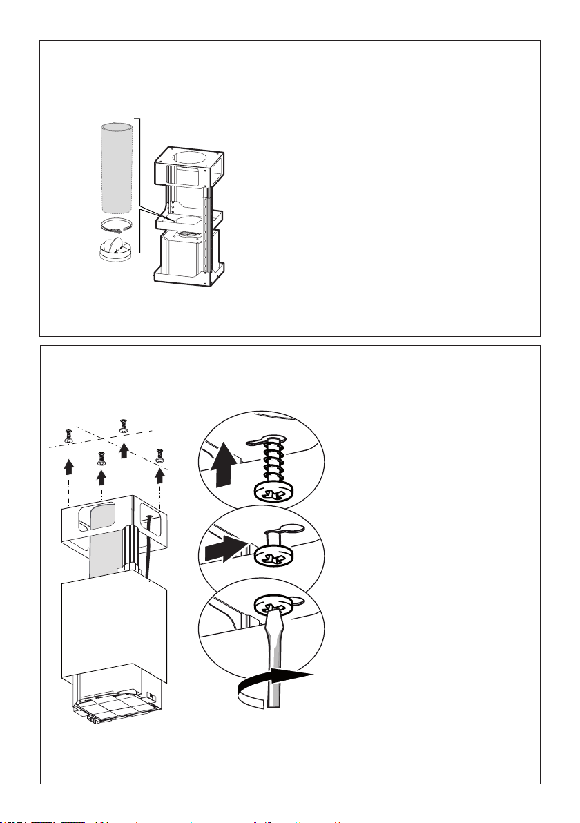
12
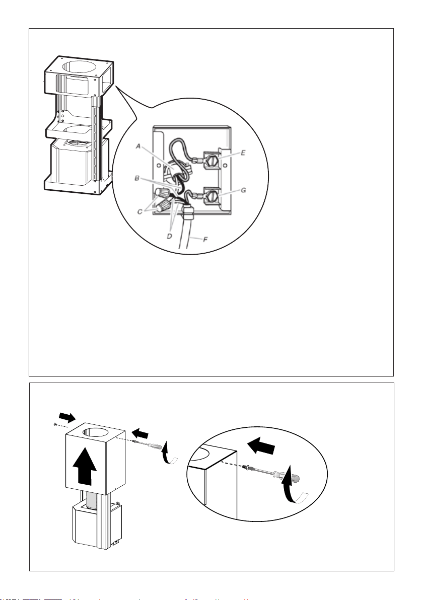
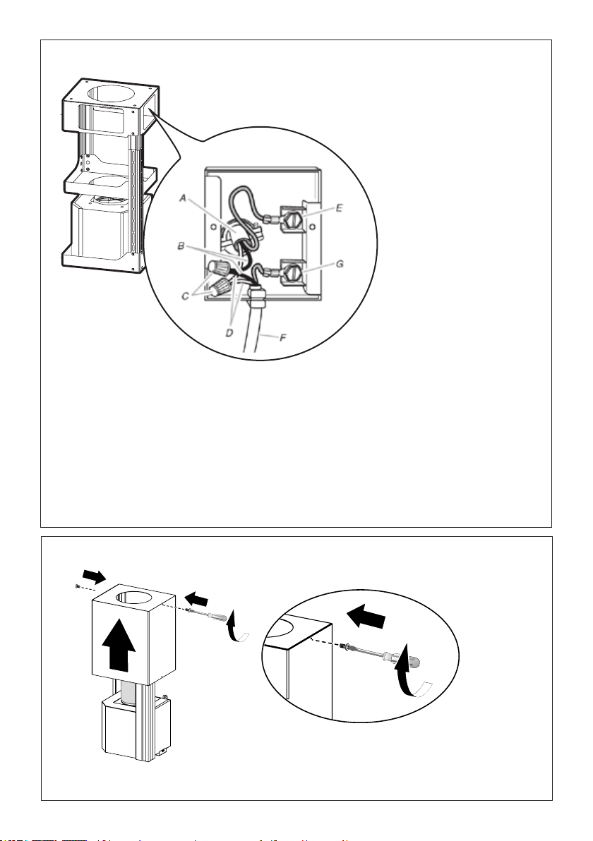
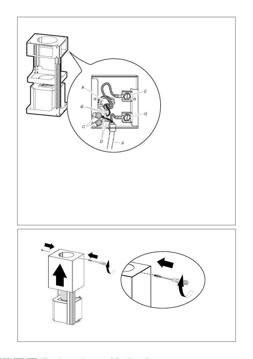
Installation of wiring
connection
Remove the cover from the
eldwiringcompartment.
DO NOT turn on the power until
installation is complete!
Connect the Power Supply
Cable to the rangehood.
Connect the Green (Green and
Yellow) ground wire under the
Green grounding screw. Attach
the White lead of the power
supply to the White lead of the
rangehood with a twist-on type
wire connector.
Attach the Black lead of the
power supply to the Black lead
of the rangehood with a twist-
on type wire connector.
Replacetheeldwiringcompart-
mentcoverandthegreaselters.
A. Home power supply cable
B. Black wires
C. UL listed wire connectors
D. White wires
E. Green (or bare) ground wire from home power supply
connected to green ground screw
F. Range hood power supply cable
G. Range hood power supply cable connected to green
ground screw
Version 02/12 - Page 8
FIGURE 13
MAKE THE ELECTRICAL CONNECTION
Remove the cover from the eld wiring compartment. (SEE
FIGURE 11) DO NOT turn on the power until installation is
complete! Connect the Power Supply Cable to the rangehood.
Connect the Green (Green and Yellow) ground wire under the
Green grounding screw. Attach the White lead of the power
supply to the White lead of the rangehood with a twist-on type
wire connector. Attach the Black lead of the power supply
to the Black lead of the rangehood with a twist-on type wire
connector.
1. The UPPER CHIMNEY
COVER (C in FIGURE 13)
attaches to the top of the
support structure using two
screws provided (G in FIGURE
13). If using the High Ceiling
Chimney Kit, use the UPPER
CHIMNEY COVER supplied
with the kit. Slide up and
attach the UPPER CHIMNEY
COVER.
2. Attach the duct work to the
DAMPER (M in FIGURE 1).
Make sure to seal all joints with
duct tape to prevent leaks.
3. The LOWER CHIMNEY
COVER (B in FIGURE 13)
attaches using two screws
provided (G in FIGURE 13).
Install the LOWER CHIMNEY
COVER by sliding it up over
the support and the UPPER
CHIMNEY COVER.
For ductless installations, line up the DUCTLESS DIVERTER
EXTENSIONS HORIZONTAL (B in FIGURE 12) with the holes
in the LOWER CHIMNEY COVER (D in FIGURE 12) and snap
in the VENT GRIDS (C in FIGURE 12).
INSTALLING THE RANGEHOOD
A. Home power supply cable
B. Black wires
C. UL listed wire connectors
D.White wires
E. Green (or bare) ground wire from home power supply
connected to green ground screw
F. Range hood power supply cable
G.Range hood power supply cable connected to green
ground screw
FIGURE 11
Ductless installations require
a Ductless Conversion
Kit whose components are
pictured in FIGURE 12. Do
not use the DAMPER (M
in FIGURE 1) for ductless
installations. The LOWER
CHIMNEY COVER ( B
in FIGURE 1) should be
discarded and replaced by
the new one with holes from
the Ductless Conversion Kit
(D in FIGURE 12).
As indicated in FIGURE
12, place the DUCTLESS
DIVERTER (A) over the
exhaust opening of the EASY
CUBE (E). Fit the DUCTLESS
DIVERTER EXTENSIONS
HORIZONTAL (B) into the
DIVERTER (A).
FIGURE 12
FOR DUCTLESS INSTALLATIONS
9
10
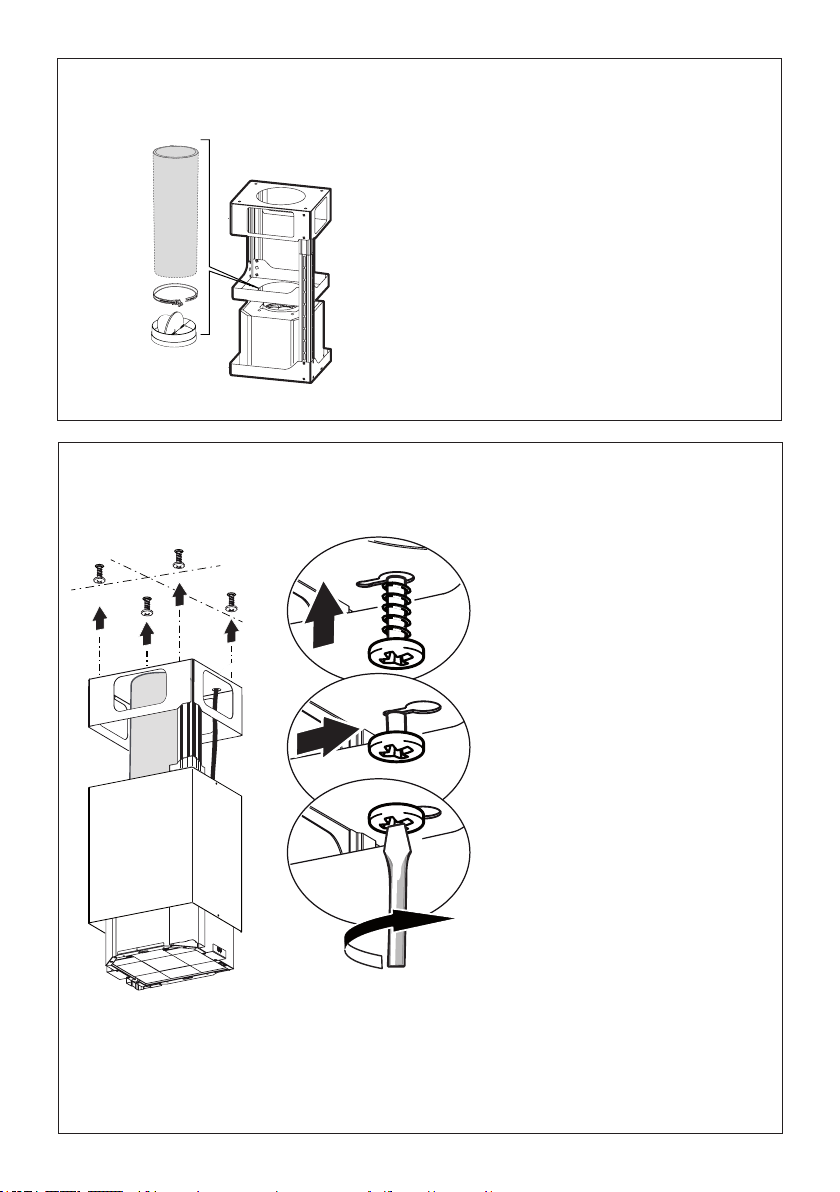
Positiontheupperchimneysectionandxtheupperparttotheframeusingthe2screwsremovedpreviously.
Attachment of Upper and Lower Flues

13
12
Similarly,positionthelowerchimneysectionandxthelowerparttotheframeusingthe2screws
removed previously.
11
Only For Ductless Installations
Version 02/12 - Page 8
FIGURE 13
MAKE THE ELECTRICAL CONNECTION
Remove the cover from the eld wiring compartment. (SEE
FIGURE 11) DO NOT turn on the power until installation is
complete! Connect the Power Supply Cable to the rangehood.
Connect the Green (Green and Yellow) ground wire under the
Green grounding screw. Attach the White lead of the power
supply to the White lead of the rangehood with a twist-on type
wire connector. Attach the Black lead of the power supply
to the Black lead of the rangehood with a twist-on type wire
connector.
1. The UPPER CHIMNEY
COVER (C in FIGURE 13)
attaches to the top of the
support structure using two
screws provided (G in FIGURE
13). If using the High Ceiling
Chimney Kit, use the UPPER
CHIMNEY COVER supplied
with the kit. Slide up and
attach the UPPER CHIMNEY
COVER.
2. Attach the duct work to the
DAMPER (M in FIGURE 1).
Make sure to seal all joints with
duct tape to prevent leaks.
3. The LOWER CHIMNEY
COVER (B in FIGURE 13)
attaches using two screws
provided (G in FIGURE 13).
Install the LOWER CHIMNEY
COVER by sliding it up over
the support and the UPPER
CHIMNEY COVER.
For ductless installations, line up the DUCTLESS DIVERTER
EXTENSIONS HORIZONTAL (B in FIGURE 12) with the holes
in the LOWER CHIMNEY COVER (D in FIGURE 12) and snap
in the VENT GRIDS (C in FIGURE 12).
INSTALLING THE RANGEHOOD
A. Home power supply cable
B. Black wires
C. UL listed wire connectors
D.White wires
E. Green (or bare) ground wire from home power supply
connected to green ground screw
F. Range hood power supply cable
G.Range hood power supply cable connected to green
ground screw
FIGURE 11
Ductless installations require
a Ductless Conversion
Kit whose components are
pictured in FIGURE 12. Do
not use the DAMPER (M
in FIGURE 1) for ductless
installations. The LOWER
CHIMNEY COVER ( B
in FIGURE 1) should be
discarded and replaced by
the new one with holes from
the Ductless Conversion Kit
(D in FIGURE 12).
As indicated in FIGURE
12, place the DUCTLESS
DIVERTER (A) over the
exhaust opening of the EASY
CUBE (E). Fit the DUCTLESS
DIVERTER EXTENSIONS
HORIZONTAL (B) into the
DIVERTER (A).
FIGURE 12
FOR DUCTLESS INSTALLATIONS
Ductless installations require a Ductless
Conversion Kit whose components are
pictured in FIGURE 12.
Do not use the DAMPER for ductless
installations. The LOWER CHIMNEY COVER
should be discarded and replaced by the
new one with holes from the Ductless
Conversion Kit (D in FIGURE 12).
As indicated in FIGURE 12, place the
DUCTLESS DIVERTER (A) over the exhaust
opening of the EASY CUBE (E). Fit the
DUCTLESS DIVERTER EXTENSIONS
HORIZONTAL (B) into the DIVERTER (A).
14
13
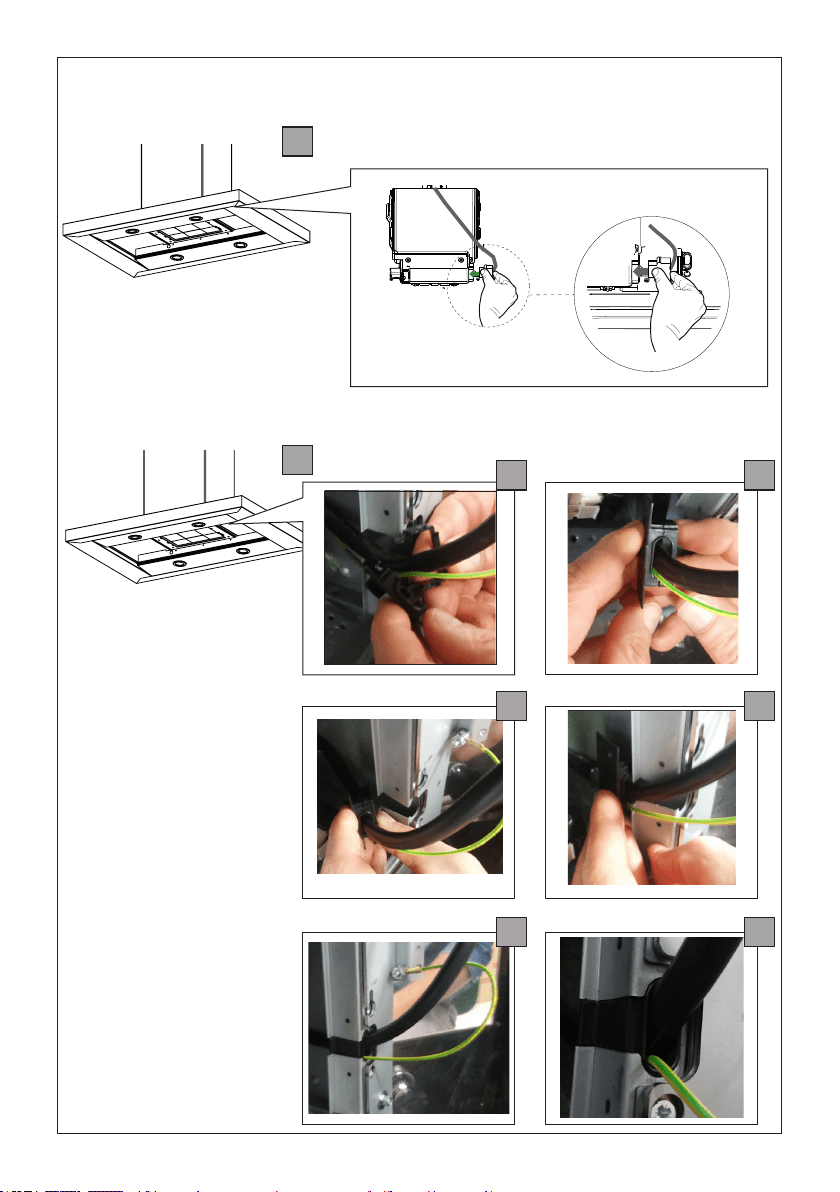
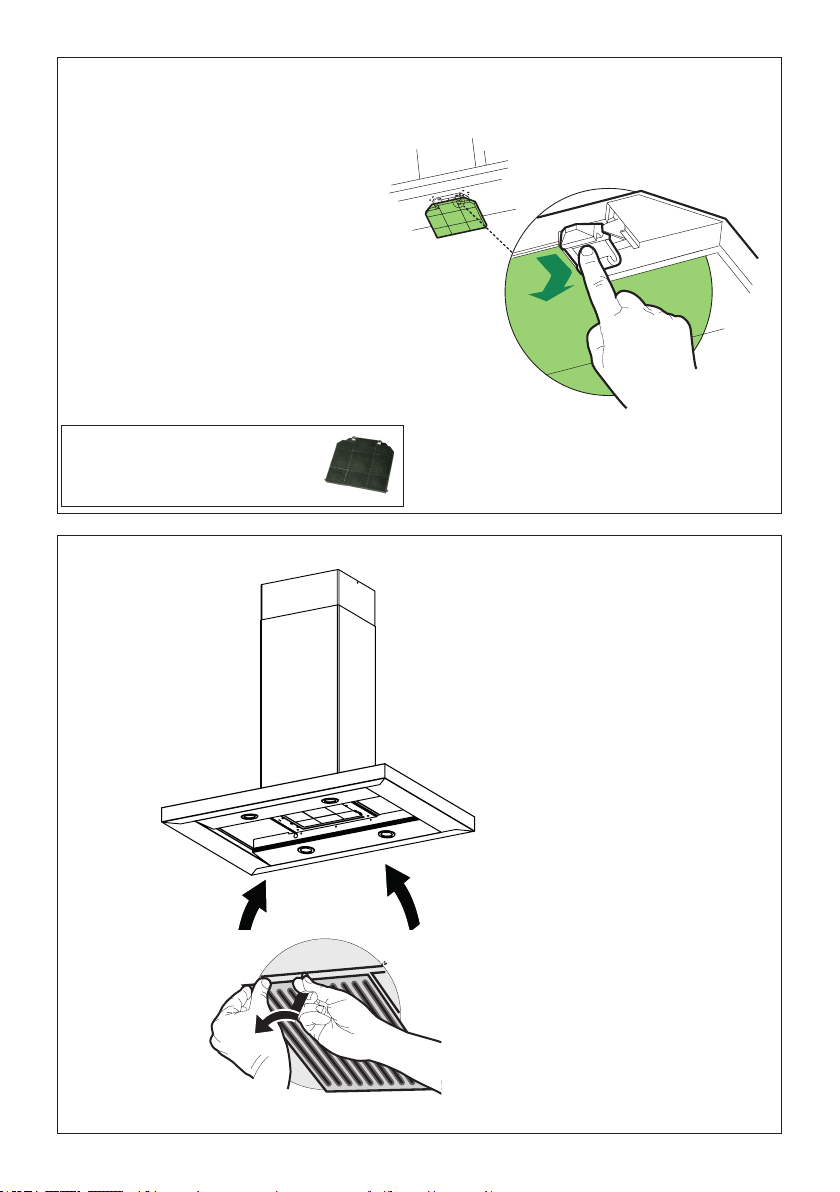
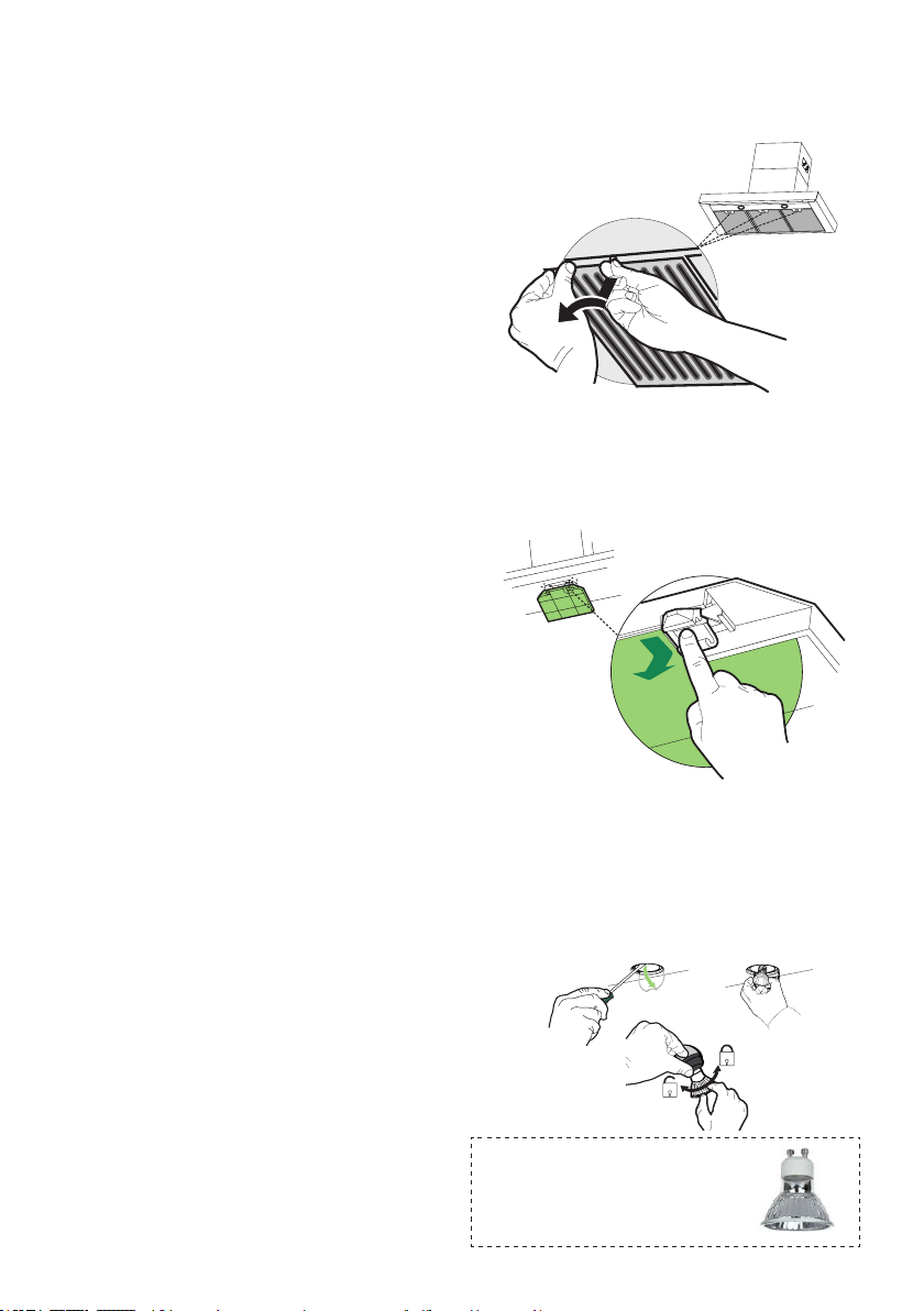
Removethegreaseltersfromthehoodcanopy.
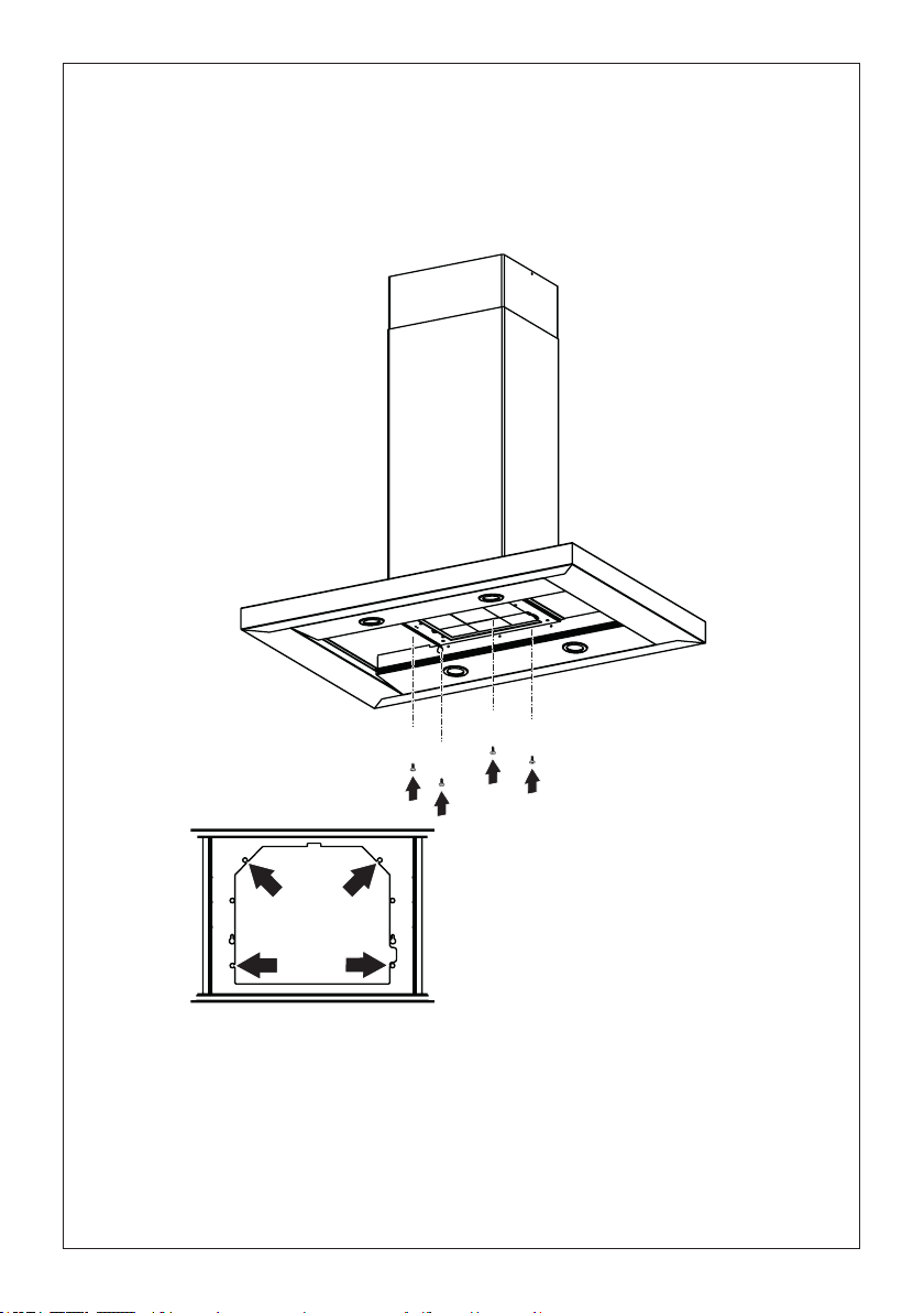
Removeanyactivatedcharcoallters.
Workingfrombelow,xthehoodcanopytotheframewhereindicated,usingthe4screws12q,then
tighten all the screws securely.
Attachment of Hood Canopy
I
I
T[
[

15
1
2
14
FixtheCableatthe
spaceindicatedwith
thelasticxingcable
component11 as
shownwithoutstress
thewiring,grounding
included.
Connecttheconnectorofcablefrom
theHoodBodytotheBloweras
shown.
Make the Internal Electrical Connection
a
c
e
b
d
f
16
15
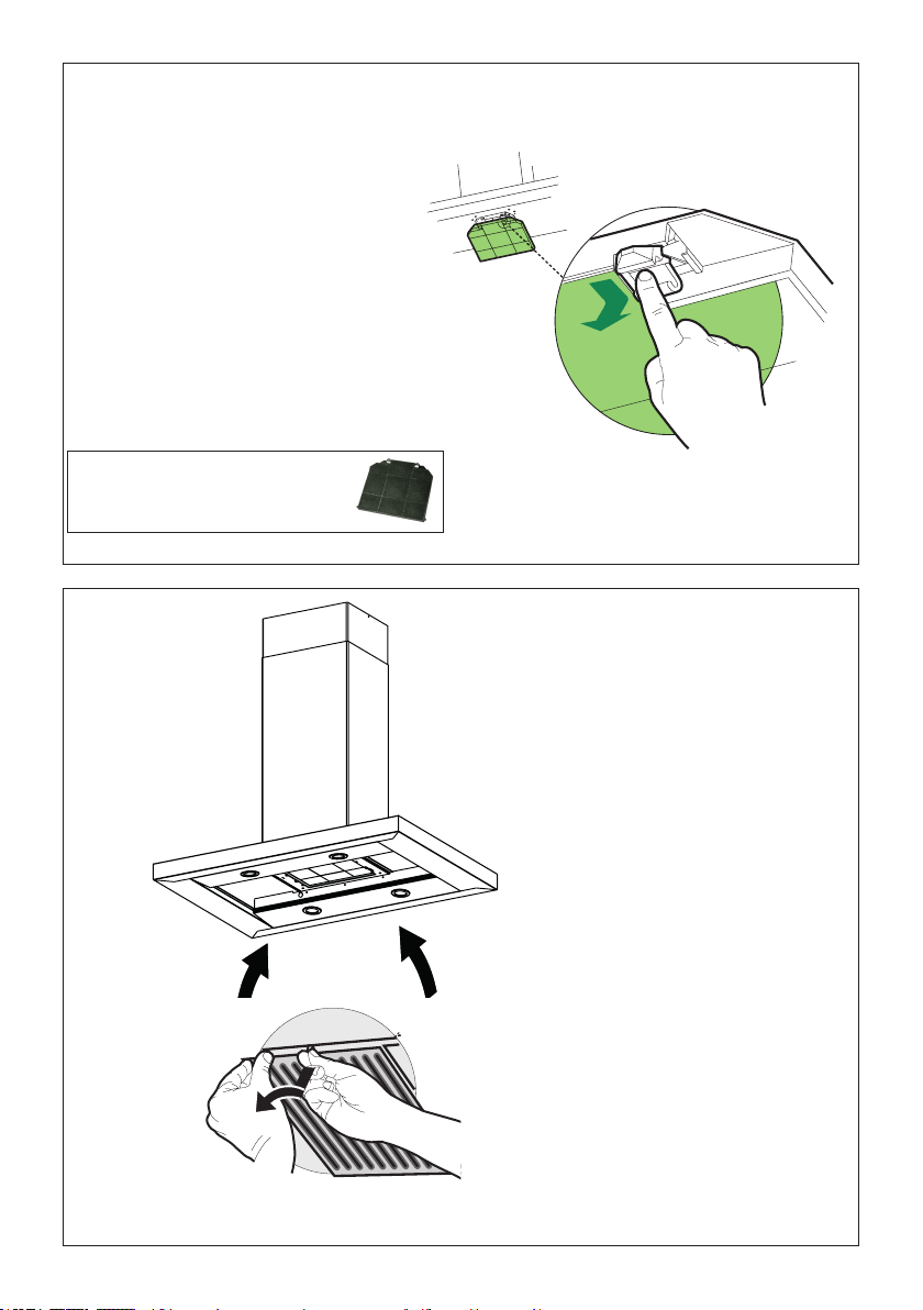
For Non-Ducted Recirculation
Option
Attach a
charcoal
lterinthe
correct
positionand
blockitby
thexing
hooksas
shown.
Unlockthexinghooks(towardsthebackofthe
inserthood)toremove.
Reinstall the metal grease
ltersfromthehoodcanopy.
16
RequiredActivatedCharcoalFilter
Accessory-sku#-FILTER2.

17
USE AND CARE INFORMATION
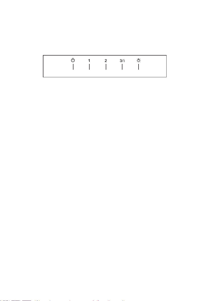
T1 T2 T3 T4 L
LT1 T2 T3 T4
For Best Results
Startthe rangehood severalminutes before cookingto developproper airow.Allowthe
rangehoodtooperateforseveralminutesaftercookingiscompletetoclearallsmokeand
odorsfromthekitchen.
T1.Fanoffbutton:turntheblowerOff.Thefancanbeoperatedbypressinganyofthefansettingbuttons.
Holddownthisbuttonfor2secondstoactivateDelayofffunctionwhichwillkeepthefanonfor15
minutesandautomaticallyshutoff.
T2.Fansettingsbuttons:Lowspeed.
T3.Fansettingsbuttons:Mediumspeed.
T4.Fansettingsbuttons:Highspeed/Intensivespeed.
Holddownthebuttonfor2secondstoactivatetheintensivespeed,whichistimedtorunfor6
minutes.Attheendofthistimeitwillautomaticallyreturntothespeedsetbefore.Suitabletodeal
withmaximumlevelsofcookingfumes.
L. Lightbutton:On/Offswitchforthelights.
NOTE:IfyourproducthashadaCFMadjustment,refertotheCFMadjustmentmanualfortheinfor-
mation.Somemotorspeedsorfunctionsmaybereduced.
18
Cleaningmetalgreaselters
Theltersmustbecleanedevery2monthsofoperation,
or more frequently for particularly heavy usage, and can
be washed in a dishwasher.
• Removetheltersoneatatimebysupportingthemwith
one hand and turning the safety knobs (pull and turn).
• Wash the Filters without bending them, and leave them
to dry completely before replacing. (If the surface of
thelterchangescolorastimegoesby,thiswillhave
absolutelynoeffectontheefciencyofthelteritself.)
• Retthemandxthemusingthesafetyknobspro-vided
(pull and turn).
• Nowatercanbepresentinltersbeforeinstallingback
in hood.
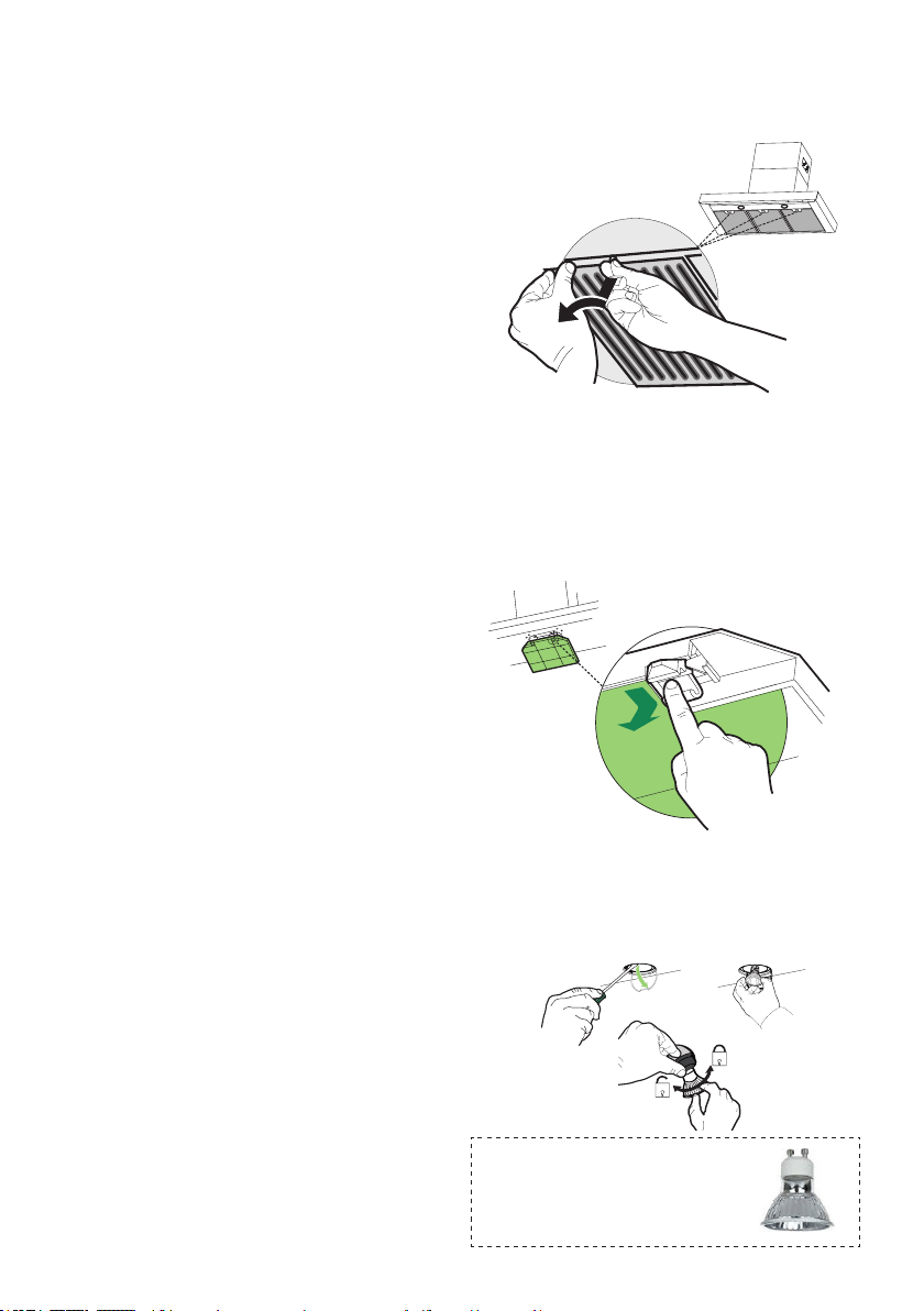
Replacing Activated Charcoal Filter
The lter is not washable and cannot be regenerated,
and must be replaced approximately every 4 months of
operation, or more frequently for particularly heavy usage.
• Remove the Filters one at a time, pushing them to-
wards the back of the unit and at the same time pulling
downward.
• Removethesaturatedcharcoallterbyreleasingthe
xinghooks.
• Fitthenewlterandfastenitinitscorrectposition.
• Replace, taking care to ensure that the handle faces
forwards.
Caution:"Whenusedinrecirculationmode,to
ReducetheRiskofFireandShockuseonlyconver-
sionkitModelFILTER2".
Gu10self-ballastedledlamps
–listedinaccordancewithul
1993/nmx-j-578/1-ance/csa
c22.2No.1993
Lighting unit
• Remove the snap-on lamp cover by levering it from
under the metal ring, supporting it with one hand.
• Replace the lamp with a new one of the same type,
making sure that you insert the two pins properly into
the housings on the lamp holder.
• Replace the snap-on lamp cover.

19
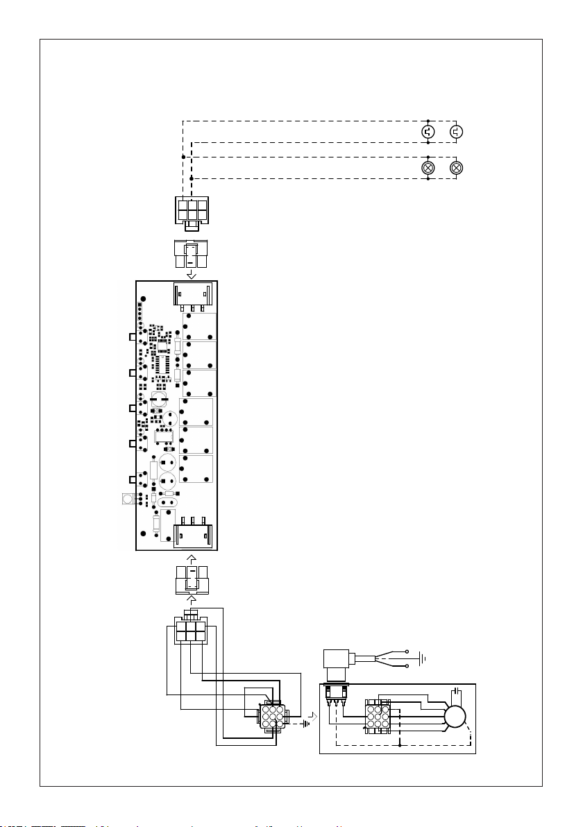
Wiring Diagram
991.0530.011 H90-503
D00004494_00
991.0530.011 H90-503
D00004494_00
120V60Hz
20
January 4, 2016
FABER CONSUMER WARRANTY & SERVICE
All Faber products are warranted against any defect in materials or workmanship for the original purchaser
for a period of 1 year from the date of original purchase (requires proof of purchase). This warranty covers
labor and replacement parts. Faber, at its option, may repair or replace the product or components
necessary to restore the product to good working condition. To obtain warranty service, contact the dealer
from whom you purchased the range hood, or the local Faber distributor. If you cannot identify a local Faber
distributor, contact us at (508) 358-5353 for the name of a distributor in your area.
The following is not covered by Faber's warranty:
1. Service calls to correct the installation of your range hood, to instruct you how to use your range hood, to
replace or repair house fuses or to correct house wiring or plumbing.
2. Service calls to repair or replace range hood light bulbs, fuses or filters. Those consumable parts are
excluded from warranty coverage.
3. Repairs when your range hood is used for other than normal, single-family household use.
4. Damage resulting from accident, alteration, misuse, abuse, fire, flood, acts of God, improper installation,
installation not in accordance with electrical or plumbing codes or Faber documentation, or use of products
not approved by Faber.
5. Replacement parts or repair labor costs for units operated outside the United States or Canada, including
any non-UL or C-UL approved Faber range hoods.
6. Repairs to the hood resulting from unauthorized modifications made to the range hood.
7. Expenses for travel and transportation for product service in remote locations and pickup and delivery
charges. Faber range hoods should be serviced in the home.
THIS WARRANTY DOES NOT ALLOW RECOVERY OF INCIDENTAL OR CONSEQUENTIAL DAMAGES, INCLUDING, WITHOUT
LIMITATION, DIRECT, INDIRECT, INCIDENTAL, SPECIAL OR CONSEQUENTIAL DAMAGES, PERSONAL INJURY/WRONGFUL
DEATH OR LOST PROFITS FABER WARRANTY IS LIMITED TO THE ABOVE CONDITIONS AND TO THE WARRANTY PERIOD
SPECIFIED HEREIN AND IS EXCLUSIVE. EXCEPT AS EXPRESSLY SPECIFIED IN THIS AGREEMENT, FABER DISCLAIMS ALL
EXPRESS OR IMPLIED CONDITIONS, REPRESENTATIONS, AND WARRANTIES INCLUDING, WITHOUT LIMITATION, ANY
IMPLIED WARRANTIES OF MERCHANTABILITY OR FITNESS FOR A PARTICULAR PURPOSE
.
This warranty gives you specific legal rights that may vary from state to state.
Model#: ______________________________ Serial #: _____________________________

21
VEUILLEZ LIRE ET CONSERVER LA PRÉSENTE NOTICE AVANT DE
COMMENCER L'INSTALLATION DE LA HOTTE DE CUISINE
AVERTISSEMENT : POUR RÉDUIRE LE RISQUE D'UN FEU DE GRAISSE SUR LA TABLE DE
CUISSON:
a) Ne laissez jamais sans surveillance les éléments de la surface de cuisson à température élevée.
Les bouillonnements excessifs peuvent provoquer de la fumée et les débordements de graisse
peuvents'enammer.L'huiledoitêtrechaufféelentement,àunetempératurebasseoumoyenne.
b) Assurez-vous de toujours mettre en marche le ventilateur de la hotte lorsque vous cuisinez à
températureélevéeoupréparezunmetsambé(p.ex.crêpesSuzette,cerisesjubilé,bœufambé).
c) Nettoyez régulièrement les ventilateurs d'aspiration. Assurez-vous de ne pas laisser de la
graisses'accumulersurleventilateurouleltre.
d)Utiliseztoujoursdespoêlesetcasserolesdelatailleappropriée.Utiliseztoujoursdesustensiles
de cuisine de la taille adaptée à celle de l'élément chauffant.
AVERTISSEMENT:-POURPRÉVENIRLESBLESSURESENCASDEFEUDEGRAISSESURLA
TABLEDECUISSON,SUIVEZLESRECOMMANDATIONSSUIVANTES*:
a) ÉTOUFFEZ LES FLAMMES à l'aide d'un couvercle hermétique, d'une plaque à biscuits ou d'un
plateau métallique, puis éteignez le brûleur. FAITES ATTENTION AUX BRÛLURES. Si le feu ne
s'éteint pas immédiatement, QUITTEZ LES LIEUX ET APPELEZ LES POMPIERS.
b) NE PRENEZ JAMAIS UNE CASSEROLE EN FLAMME - Vous pourriez vous brûler.
c) N'UTILISEZ JAMAIS DE L'EAU, ni un linge à vaisselle ou un torchon mouillé, pour éteindre le
feu. Cela pourrait provoquer une violente explosion de vapeur.
d)UtilisezunextincteurUNIQUEMENTsi:
1. Vousêtescertainqu'ils'agitd'unextincteurdeclasseABCetquevousconnaissezbien
son mode d'emploi.
2. Le feu est de faible intensité et se limite à l'endroit où il a démarré.
3. Les pompiers ont déjà été appelés.
4. Unevoiedesortiesetrouvederrièrevouspendantquevouséteignezlesammes.
* D'après le guide «Kitchen Firesafety Tips» publié par la NFPA aux États-Unis
AVERTISSEMENT - POUR RÉDUIRE LE RISQUE D'INCENDIE OU DE CHOC ÉLECTRIQUE, n'utilisez
jamais ce ventilateur en association avec un dispositif de réglage de vitesse à semi-conducteurs.
AVERTISSEMENT - POUR RÉDUIRE LES RISQUES D'INCENDIE, DE CHOC ÉLECTRIQUE OU
DEBLESSURECORPORELLE,RESPECTEZLESINSTRUCTIONSSUIVANTES:
1. Utilisez cet appareil uniquement de la façon prévue par le fabricant. Pour toute question,
communiquez avec le fabricant.
2. Avant de procéder à l'entretien ou au nettoyage de l'appareil, coupez l'alimentation au
niveau du panneau électrique et verrouillez-le pour vous assurer que l'électricité n'est pas
rétablie accidentellement. S'il n'est pas possible de verrouiller le dispositif d'interruption de
l'alimentation,afchezdefaçonfermeetbienvisibleunavisdedanger,parexempleàl'aide
d'une étiquette sur le panneau.
ATTENTION:Destinéàunusagedeventilationgénéraleuniquement.N'utilisezpascedispositif
pour l'aspiration de vapeurs ou de matériaux dangereux ou explosifs.
AVERTISSEMENT - POUR RÉDUIRE LES RISQUES D'INCENDIE, DE CHOC ÉLECTRIQUE OU
DEBLESSURECORPORELLE,RESPECTEZLESINSTRUCTIONSSUIVANTES:
1. L'installationetlebranchementélectriquedoiventêtreréalisésparuntechnicienqualié
et conformément à tous les codes et normes en vigueur, incluant ceux concernant la con-
struction à l'épreuve du feu.
2. Andegarantirunecombustionetuneévacuationadéquatesdesgazparlesconduites
de la cheminée des appareils à combustion, une bonne aération est nécessaire pour éviter
le refoulement. Respectez les lignes directrices fournies par le fabricant du matériel chauf-
fant, ainsi que les normes de sécurité comme celles publiées par la National Fire Protection
Association(NFPA)etlaAmericanSocietyforHeating,RefrigerationandAirConditioning
Engineers(ASHRAE)auxÉtats-Unis,ainsiquelescodesenvigueurdansvotrerégion.

22
3. Lorsque vous faites une ouverture ou percez dans un mur ou le plafond, veillez à ne pas
endommagerleslsélectriquesoud'autresdispositifscachés.
4. Lesventilateurscanalisésdoiventtoujoursêtreraccordésàl'extérieur.
T
OUTE OUVERTURE DANS LE MUR OU LE PLANCHER À PROXIMITÉ DE LA HOTTE DOIT
ÊTRE SCELLÉE.
Un espace libre d'au moins 24" est requis entre le bas de la hotte et la surface de cuisson ou le
comptoir. Cette hotte a été homologuée par l'UL à cette distance de la surface de cuisson.
L’espace libre minimal requis peut-être plus grand, selon la réglementation en matière de construction
de votre région. Pour les cuisinières à gaz et les cuisinières combinées, un espace minimal de 30"
est recommandé et pourrait être exigé.
Les armoires suspendues de chaque côté de l'appareil doivent se trouver à au moins 18" de la
surface de cuisson ou du comptoir. Consultez la notice d'installation de la surface de cuisson ou de
la cuisinière fournie par le fabricant avant de pratiquer des ouvertures.
INSTALLATION DANS UNE MAISON MOBILE L'installation de cette hotte doit être conforme à la
Partie 3280 de la norme Manufactured Home Construction and Safety Standards, Title 24 CFR
(précédemment la partie 280 de la norme Federal Standard for Mobile Home Construction and
Safety, Title 24, HUD). Consultez la che technique électrique.
CRITÈRES DE VENTILATION
Déterminez quelle méthode de ventilation est mieux adaptée à votre application. Les conduits peuvent
passer par le mur ou le toit.
Pour garantir une meilleure efcacité, la longueur des conduits et le nombre de coudes doivent être le
plus limités que possible. Le diamètre des conduits devrait être uniforme. N'installez pas deux coudes
ensemble. Utilisez un ruban pour canalisations an de sceller tous les joints du système de conduits.
Utilisez un calfeutrage pour sceller les ouvertures dans le mur extérieur ou le plancher, autour du clapet.
Il n'est pas recommandé d'utiliser des conduits exibles. Les conduits exibles provoquent une con-
tre-pression et de la turbulence qui diminuent grandement l'efcacité de l'appareil.
Assurez-vous que l'espace libre dans le mur ou le plancher est sufsant pour le conduit d'évacuation
avant de pratiquer les ouvertures. Ne coupez jamais une poutre ou un chevron, sauf si c'est absolu-
ment nécessaire. S'il s'avère nécessaire de couper une poutre ou un chevron, la construction d'un
renforcement est requise.
AVERTISSEMENT - Pour réduire le risque d'incendie, utilisez uniquement des conduits métalliques.
ATTENTION - Pour réduire le risque d'incendie et pour évacuer adéquatement l'air, assu-
rez-vousderaccorderlesconduitsàl'extérieur–Nediffusezpasl'aird'évacuationdans
des espaces à l'intérieur des murs ou du plafond, ou encore à l'intérieur d'un grenier, d'une
galerie technique ou d'un garage.
• Le système de ventilation DOIT déboucher à l'extérieur.
• NE FAITES PAS déboucher les conduits dans un grenier ou un autre endroit fermé.
• N'UTILISEZ PAS un clapet de sécheuse mural de 4" .
• Il n'est pas recommandé d'utiliser des conduits exibles.
• N'ENTRAVEZ PAS le ux de l'air de combustion et de ventilation.
• Le non-respect des exigences en matière de ventilation pourrait entraîner un incendie.
AVERTISSEMENT
!
23
FICHE TECHNIQUE ÉLECTRIQUE
Une alimentation de courant alternatif de 120 volt à 60 Hz est requise sur un circuit à fusible distinct
de 15 ampères. Il est recommandé d'installer un fusible temporisé ou un disjoncteur. Le fusible doit
être calibré conformément aux codes en vigueur pour les caractéristiques nominales électriques de
l'appareil, indiquées sur la plaque signalétique située à l'intérieur de l'appareil, à proximité du com-
partiment des câblages externes.
INSTALLATION ÉLECTRIQUE AVEC BOÎTIER DE CÂBLAGES
CET APPAREIL DOIT ÊTRE UNIQUEMENT BRANCHÉ À L'AIDE DE FILS DE CUIVRE. Le calibre des
ls doit être conforme aux critères de la dernière édition du National Electrical Code, de l'ANSI/NFPA
70 et de l'ensemble des codes et réglementations en vigueur. Le calibre des ls et les connexions
doivent être adaptés aux caractéristiques nominales de l'appareil. Il est possible de se procurer un
exemplaire des normes indiquées ci-dessus en communiquant avec:
National Fire Protection Association
Batterymarch Park
Quincy, Massachusetts 02269 (États-Unis)
Cet appareil devrait être branché directement au sectionneur à fusible (ou au disjoncteur) par un câble
exible de cuivre avec blindage ou gaine non métallique. Laissez un peu de jeu dans le câble pour
permettre le déplacement de l'appareil si des travaux d'entretien s'avéraient nécessaires. Un raccord
de conduit homologué par l'UL de 1/2" doit être installé aux deux extrémités du câble d'alimentation
(au niveau de l'appareil et de la boîte de liaison).
Lors de la réalisation du branchement électrique, réalisez un trou de 11/4" dans le mur. S'il s'agit
d'un trou dans le bois, il doit être poncé pour le rendre lisse. S'il s'agit d'un trou dans le métal, un
passe-ls est requis.
• Une mise à la terre électrique est requise pour cette hotte.
• N'UTILISEZ PAS un tuyau d'eau froide pour la mise à la terre si celui-ci est branché par des
joints en plastique, par des rondelles non métalliques ou d'autres matériaux.
• N'UTILISEZ PAS une conduite de gaz pour la mise à la terre.
• N'INSTALLEZ PAS un fusible sur le circuit neutre ou le circuit de mise à la terre. La présence
d'un fusible dans le circuit neutre ou de mise à la terre peut entraîner un choc électrique.
• Consultez un électricien qualié si vous n'êtes pas certain de la mise à la terre de la hotte.
• Le non-respect des exigences de la che technique électrique pourrait entraîner un incendie.
AVERTISSEMENT
!
Avertissementdelaproposition65del'ÉtatdeCalifornie(USseulement)
ATTENTION
Ce produit contient des produits chimiques connus de l'État de Californie pour causer le
cancer et des malformations congénitales ou d'autres problèmes de reproduction.
Pour plus d'informations, visitez www.P65Warnings.ca.gov
24
DIMENSIONS DE LA HOTTE
0,10$;
Min. 24" Min. 30"
25
PIÈCES PRINCIPALES
Pièces requises
-Conduitmétallique6"circulaire
Accessoires disponibles
Composants
Réf. Qté Composants du produit
1 1 Bâti de la hotte, avec : Com-
mandes,éclairages,ltres,ventilateur.
2 1 Cheminée télescopique comprenant :
2.1 1 Section supérieure
2.2 1 Section inférieure
7.1 1 Châssis télescopique avec
ventilateur d'aspiration, composé de :
7.1a 1 Châssis supérieur
7.1b 1 Châssis inférieur
10 1 Registre ø 5 7/8"
11 1 PlastiqueforCâblexation.
Réf. Qté Composants d'installation
12q 4 Vis 1/8" x 1/4"
21 1 Gabarit de perçage
Qté Documentation
1 Mode d'emploi
-Troussedecheminéepourplafondshauts,pourremplacerleconduitsupèrieurde
cheminée.-Nod'articleHIGH2.
-Troussesansconduit-Comprenddéecteurderecyclage,ltresàcharbon,cheminée
inférieureavecgrilled'évent-Nod'articleDUCT2
-Filtreàcharbonactifaccessoire-Nod'articleFILTER2
-Télécommandesanslaccessoire-REMCTRL2
10
1
2.2
2.1
21
7.1
12q
7.1a
7.1b
11
26
6 "
Choisissez la méthode de canalisation
Exigelatroussed'accessoires
sansconduit(achetée
séparément)
Recyclage sans canalisationInstallation avec ventilation
canalisée

27
1
Ø 10 mm
x4
21
1 1/4"
AVERTISSEMENT
!
COMPTE TENU DE LA DIMEN-
SION ET DU POIDS DE CETTE
HOTTE, LE SOCLE DOIT ÊTRE
SOLIDEMENT ANCRÉ AU PLA-
FOND. Si le plafond est en plâtre
ou en plaque de plâtre, le socle
doit être ancré aux poutres. Si
cela n'est pas possible, une
structure de soutien doit être
construite derrière le plâtre ou
la plaque de plâtre. Le fabricant
ne peut être tenu responsable
en cas de blessures ou de
dommages provoqués par une
mauvaise installation.
Nepratiquezaucuneouvertureavantd'avoirdécidésil'installationseracanaliséeounon,
puisplaniezenconséquence.
Placezuneprotectionépaissesurlasurfacede
cuisson,lacuisinièreencastréeoulecomptoir
pouréviterlesdommagesoulasaleté.
Déterminezl'endroitoùlahotteserainstallée
etmarquez-laclairementsurleplafondàl'aide
d'uncrayon.
Ungabarit21pour le montage du socleest
fournidansl'emballage.Utilisezcemodèlepour
indiquerlestrousquiservirontàxer
lesocleauplafond.
Déterminez les ouverturesnécessaires pour
lesconduitsetpratiquez-les.L'ouverturepour
lacanalisationestreprésentéesurlegabarit
demontage.Installez
lesconduitsavantdemonterlahotte.
Déterminezl'emplacementadéquatpourlecâble
d'alimentation, comme indiqué sur le gabarit.
Utilisezunemèchede11/4"pourpercercetrou.
Faitespasserlecâbled'alimentation.Utiliserun
calfeutragepourscellerautourdutrou.
Une pièce à défoncer pour le passage de
l'alimentationélectriqueduplafondestsituée
au sommet du châssis. Ne branchez par le
câbled'alimentationauboîtierdeconnexionet
n'alimentezpaslahotteàcemoment.Acheminez
lecâbleélectriqueduplafondjusqu'auboîtier
deconnexionsurlahotte.
28
2
3
4
1
4
MIN
740
mm
MAX
940
mm
2
3
5
6
Si vous devez régler la hauteur du châssis, procédez
comme suit :
• Détachez les vis métriques qui unissent les deux
colonnes, situées sur les côtés du châssis (1, 2,
3, 4, 5, 6).
• Réglez le châssis à la hauteur requise, puis
remettez en place toutes les vis enlevées comme
ci-dessus.
Dévissezlesdeuxvisquixentlasectioninférieure
de la cheminée et détachez-la du châssis inférieur.
Dévissezlesdeuxvisquixentlasectionsupérieure
de la cheminée et détachez-la du châssis supérieur.
Lesconduitsdecheminéesdoiventêtreenlevésavantl'installationdela
hotte
0,10$;
29
14. REMOVING THE MIDDLE TRESTLE COMPONENT
NOTE: The chimney structure can reduce down to a 27 " minimum height. To reduce the height,
the middle section of the support structure needs to be removed.
Out of the box, the minimum chimney length is 32 ".
Insure the the installation process outlined in the U&C is followed and there is sufficient stability with the
middle section removed.
5
REMARQUE: La structure de la cheminée peut réduire jusqu'à une hauteur minimale de 27 " . Pour
réduire la hauteur, la section médiane de la structure de support doit être retiré.
Hors de la boîte, la longueur minimale de la cheminée est de 32 ".
Aucun problème du point de vue mécanique, la rigidité est garantie par le chevauchement des colonnes.
RAIT DU COMPOSANT DE TRESTE MOYEN
6
Leconduitsupérieurdecheminéedoitêtreenplaceavantde
poursuivre l'installation
Après avoir procédé au réglage de la hauteur, insérez
la souche de cheminée supérieure à partir du haut
et laissez-la sur le châssis.
30
7
8
Prenez ensuite les vis à bois ou boulons, selon
votre installation, et vissez toutes les quatre dans
les trous d'implantation, en laissant 1/4" de la
tête des vis libre.
Installez ensuite un protège-câbles (homologa-
tion UL ou CSA) dans le boîtier de connexion,
de façon à pouvoir serrer les vis lorsque le socle
de cheminée sera ancré au plafond.
Soulevez ensuite le socle de cheminée à son
emplacement, et faites passer le câble d'ali-
mentation électrique à travers le protège-câbles.
Placez le socle de cheminée de façon à aligner
la grande ouverture des encoches en trou de
serrure sur les vis ou boulons de xation au
plafond. Poussez ensuite le socle de cheminée
de façon à ce que les boulons s'engagent dans
la partie étroite des encoches. Serrez fermement
les quatre vis ou boulons.
• Le montage du châssis doit être assez solide
pour supporter le poids de la hotte et tout stress
causé par une pression latérale occasionnelle
que pourrait subir l'appareil. Lorsque vous avez
terminé, assurez-vous que la base est stable,
même lorsque le châssis est plié.
• Dans tous les cas où le plafond n'est pas
assez fort au point de suspension, l'installateur
doit veiller à le renforcer à l'aide de plaques
et de pièces de renfort ancrées à des pièces
structurelles solides.
Pour installation avec ventilation canalisée uniquement
Installez le registre inclus avec la hotte avant de la
raccorder aux conduits.
31
9
10
Réalisation des bran-
chements
Retirez le couvercle du
compartiment des câblages
externes.
NE METTEZ PAS l'alimentation
sous tension avant d'avoir
terminé l'installation!
Branchez le câble d'alimenta-
tion à la hotte.
Branchezlelvert(vertet
jaune) de mise à la terre
sous la vis de mise à la terre
verte.Branchezlelblancde
l'alimentationaulblancdela
hotte à l'aide d'un connecteur
verrouillé par rotation.
Branchezlelnoirdel'alimen-
tationaulnoirdelahotteà
l'aide d'un connecteur verrouillé
par rotation.
Remettez le couvercle du com-
partiment des câblages externes
etlesltresàgraisseenplace.
A. Câble d'alimentation du réseau domestique
B. Fils noirs
C.Serre-lshomologuéUL
D. Fils blancs
E.Fildemiseàlaterrevert(oulnu)del'alimentation
domestique branché à la vis de mise à la terre verte
F. Câble d'alimentation de la hotte
G. Câble d'alimentation de la hotte branché à la vis de
mise à la terre verte
Placezlasectionsupérieuredelacheminéeetxezlapartiesupérieureauchâssisàl'aidedes2vis
enlevées précédemment.
Montage des cheminées supérieure et inférieure
Version 02/12 - Page 8
FIGURE 13
MAKE THE ELECTRICAL CONNECTION
Remove the cover from the eld wiring compartment. (SEE
FIGURE 11) DO NOT turn on the power until installation is
complete! Connect the Power Supply Cable to the rangehood.
Connect the Green (Green and Yellow) ground wire under the
Green grounding screw. Attach the White lead of the power
supply to the White lead of the rangehood with a twist-on type
wire connector. Attach the Black lead of the power supply
to the Black lead of the rangehood with a twist-on type wire
connector.
1. The UPPER CHIMNEY
COVER (C in FIGURE 13)
attaches to the top of the
support structure using two
screws provided (G in FIGURE
13). If using the High Ceiling
Chimney Kit, use the UPPER
CHIMNEY COVER supplied
with the kit. Slide up and
attach the UPPER CHIMNEY
COVER.
2. Attach the duct work to the
DAMPER (M in FIGURE 1).
Make sure to seal all joints with
duct tape to prevent leaks.
3. The LOWER CHIMNEY
COVER (B in FIGURE 13)
attaches using two screws
provided (G in FIGURE 13).
Install the LOWER CHIMNEY
COVER by sliding it up over
the support and the UPPER
CHIMNEY COVER.
For ductless installations, line up the DUCTLESS DIVERTER
EXTENSIONS HORIZONTAL (B in FIGURE 12) with the holes
in the LOWER CHIMNEY COVER (D in FIGURE 12) and snap
in the VENT GRIDS (C in FIGURE 12).
INSTALLING THE RANGEHOOD
A. Home power supply cable
B. Black wires
C. UL listed wire connectors
D.White wires
E. Green (or bare) ground wire from home power supply
connected to green ground screw
F. Range hood power supply cable
G.Range hood power supply cable connected to green
ground screw
FIGURE 11
Ductless installations require
a Ductless Conversion
Kit whose components are
pictured in FIGURE 12. Do
not use the DAMPER (M
in FIGURE 1) for ductless
installations. The LOWER
CHIMNEY COVER (B
in FIGURE 1) should be
discarded and replaced by
the new one with holes from
the Ductless Conversion Kit
(D in FIGURE 12).
As indicated in FIGURE
12, place the DUCTLESS
DIVERTER (A) over the
exhaust opening of the EASY
CUBE (E). Fit the DUCTLESS
DIVERTER EXTENSIONS
HORIZONTAL (B) into the
DIVERTER (A).
FIGURE 12
FOR DUCTLESS INSTALLATIONS
32
12
11
Version 02/12 - Page 8
FIGURE 13
MAKE THE ELECTRICAL CONNECTION
Remove the cover from the eld wiring compartment. (SEE
FIGURE 11) DO NOT turn on the power until installation is
complete! Connect the Power Supply Cable to the rangehood.
Connect the Green (Green and Yellow) ground wire under the
Green grounding screw. Attach the White lead of the power
supply to the White lead of the rangehood with a twist-on type
wire connector. Attach the Black lead of the power supply
to the Black lead of the rangehood with a twist-on type wire
connector.
1. The UPPER CHIMNEY
COVER (C in FIGURE 13)
attaches to the top of the
support structure using two
screws provided (G in FIGURE
13). If using the High Ceiling
Chimney Kit, use the UPPER
CHIMNEY COVER supplied
with the kit. Slide up and
attach the UPPER CHIMNEY
COVER.
2. Attach the duct work to the
DAMPER (M in FIGURE 1).
Make sure to seal all joints with
duct tape to prevent leaks.
3. The LOWER CHIMNEY
COVER (B in FIGURE 13)
attaches using two screws
provided (G in FIGURE 13).
Install the LOWER CHIMNEY
COVER by sliding it up over
the support and the UPPER
CHIMNEY COVER.
For ductless installations, line up the DUCTLESS DIVERTER
EXTENSIONS HORIZONTAL (B in FIGURE 12) with the holes
in the LOWER CHIMNEY COVER (D in FIGURE 12) and snap
in the VENT GRIDS (C in FIGURE 12).
INSTALLING THE RANGEHOOD
A. Home power supply cable
B. Black wires
C. UL listed wire connectors
D.White wires
E. Green (or bare) ground wire from home power supply
connected to green ground screw
F. Range hood power supply cable
G.Range hood power supply cable connected to green
ground screw
FIGURE 11
Ductless installations require
a Ductless Conversion
Kit whose components are
pictured in FIGURE 12. Do
not use the DAMPER (M
in FIGURE 1) for ductless
installations. The LOWER
CHIMNEY COVER ( B
in FIGURE 1) should be
discarded and replaced by
the new one with holes from
the Ductless Conversion Kit
(D in FIGURE 12).
As indicated in FIGURE
12, place the DUCTLESS
DIVERTER (A) over the
exhaust opening of the EASY
CUBE (E). Fit the DUCTLESS
DIVERTER EXTENSIONS
HORIZONTAL (B) into the
DIVERTER (A).
FIGURE 12
FOR DUCTLESS INSTALLATIONS
Delamêmefaçon,placezlasectioninférieuredelacheminéeetxezlapartieinférieureau
châssis à l'aide des 2 vis enlevées précédemment.
Pour installation sans conduit uniquement
L'installation sans conduit nécessite une
Trousse de conversion pour
installation sans conduit dont les
éléments sont représentés à la FIGURE
12.
N'utilisez pas le REGISTRE pour
l'installation sans conduit. L'HABILLAGE
INFÉRIEUR DE CHEMINÉE doit être
remplacé par celui présentant des trous
de la Trousse de conversion pour
installation sans conduit (D sur
la FIGURE 12).
Tel qu'indiqué sur la FIGURE 12, placez
le DÉFLECTEUR DE RECYCLAGE (A) sur
l'ouverture d'évacuation du EASY CUBE
(E). Placez les SORTIES HORIZONTALES
DU DÉFLECTEUR DE RECYCLAGE (B)
dans le DÉFLECTEUR (A).
33
13
Retirezlesltresàgraissedel'auventdelahotte.
Retireztoutltreàcharbonactif.
Enpassantparledessous,xezl'auventdelahotteauchâssisauxendroitsindiqués,enutilisantles4
vis 12q, puis serrez fermement toutes les vis.
Montage de l'auvent de la hotte
I
I
T[
[
34
14
Réalisation des branchements électriques internes
Fixezlecâbleà
l’espaceindiqué
parlecomposant
enplastique11,
commeillustrésans
contraintelecâblage,
miseàlaterre
incluse.
Connectezleconnecteurducâble
ducorpsduahotteauventilateur,
commeillustré.
a
c
e
b
d
f
1
2
35
15
16
Pour option non canalisée
avec recirculation d'air
Posezunltre
àcharbonà
l'emplacement
adéquatet
bloquez-le
àl'aidedes
crochetsde
xation,comme
illustré.
Déverrouillezlescrochetsdexation(vers
l'arrièredelahotteencastrable)pourles
enlever.
Remettezenplacelesltres
metalliques à graisse de
l'auvent de la hotte.
Filtreàcharbonactifaccessoire
requis-nod'article-FILTER2 (acheté
séparément).
36
T1 T2 T3 T4 L
LT1 T2 T3 T4
INFORMATIONS POUR L'UTILISATION ET L'ENTRETIEN
Pour de meilleurs résultats
Activezlahottequelquesminutesavantdecommenceràcuisinerpourcréerunuxd'air
adéquat. Laissezla hotte fonctionnerquelquesminutes après avoirni de cuisiner pour
absorbertoutelafuméeetlesodeursdelacuisine.
T1.Boutonarrêtduventilateur:éteintleventilateur.Leventilateurpeutêtrealluméenap-
puyantsurl'unoul'autredesboutonsderéglage.
Tenezceboutonenfoncépendant2secondespouractiverlafonctiondedésactivation
retardée,quiéteindraautomatiquementleventilateuraprès15minutesdemarche.
T2.Boutonsderéglageduventilateur:vitesseréduite.
T3.Boutonsderéglageduventilateur:vitessemoyenne.
T4.Boutonsderéglageduventilateur:vitesseélevée/vitesseintensive.
Tenezleboutonenfoncépendantenviron2secondespouractiverlavitesseintensive,
pouruneduréede6minutes.Aprèscedélai,lavitesseretourneraautomatiquementà
lavitessesélectionnéeprécédemment.Utilepourcontrerlesémanationsmaximalesde
cuisson.
L. Boutonpourl'éclairage:commutateurmarche/arrêtpourl'éclairage.
REMARQUE:SivotreproduitasubiunréglageCFM,reportez-vousaumanuelderéglageCFM
pourplusd'informations.Certainesvitessesdemoteurdesfonctionspeuventêtreréduites.
37
Nettoyagedesltresàgraissemétall-
iques
Lesltresdoiventêtrenettoyéstousles2moisd'utilisation,
ou plus fréquemment en cas d'utilisation particulièrement
intensive. Ils peuvent être lavés dans le lave-vaisselle.
• Décrocherlesltresl’unaprésl’autre,enlessoute-nant
d’une main et en intervenant sur les pommeaux de
sécurité spécialement prévus (tirer et tourner).
• Lavez les ltres sans les plier et laissez-les sécher
complètement avant de les remettre en place. (Si la
surface du ltre change de couleur au l du temps,
celan'auraaucunimpactsurl'efcacitédultremême.)
• Remonterlesltresenlesxantàl’aidedespom-meaux
de sécurité spécialement prévus (tirer et tour-ner).
• Aucuneeaunepeutêtreprésentedanslesltresavant
la réinstallation dans la hotte.
Remplacementdultreàcharbon
actif
Leltren'estpaslavableetnepeutpasêtrerégénéré.Il
doit être remplacé environ tous les 4 mois d'utilisation, ou
plus souvent en cas d'utilisation particulièrement intensive.
• Retirezlesltresunàun,enlespoussantversl'arrière
de l'appareil et en les tirant vers le bas simultanément.
• Retirez le ltre à charbon saturé en détachant les
crochetsdexation.
• Posez le nouveau ltre et xez-le à l'emplacement
adéquat.
• Remettez-le en place, en vous assurant que la poignée
se trouve vers l'avant.
Attention: "En mode recirculation, pour réduire le risque
d'incendie et de choc, utilisez uniquement le kit de conver-
sion Modèle FILTER2".
LampesDELàballastintégré
detypeGu10–répondantàla
normeUL1993/nmx-j-578/1-
ance/csac22.2No1993
Système d'éclairage
• Retirez l'écran protecteur de la lampe en faisant un
effet de levier sous l'anneau métallique, en le soutenant
d'une main.
• Remplacez l'ampoule avec une nouvelle du même
type, en vous assurant d'insérer correctement les deux
connecteurs dans leur logement sur le socle.
• Remettez l'écran protecteur de la lampe en place.
38
991.0530.011 H90-503
D00004494_00
991.0530.011 H90-503
D00004494_00
Schéma de câblage
120V60Hz

39
4 janvier 2016
GARANTIE LIMITÉE ET SERVICE FABER
Tous les produits Faber font l'objet d'une garantie contre les défauts de matériel et de main-
d'œuvre,accordée à l'acheteur original pour une période d'un (1) an à compter de la date d'achat initiale
(preuve d'achat requise). Cette garantie couvre les frais de main-d'œuvre et les pièces de rechange. À sa
discrétion, Faber peut réparer ou remplacer le produit ou les composants nécessaires à remettre le produit
en bon état de marche. Pour bénéficier de services prévus par la garantie, veuillez communiquer avec le
détaillant auprès duquel vous avez acheté la hotte de cuisine, ou encore avec le distributeur Faber de votre
région. Si vous n'êtes pas en mesure de localiser un distributeur Faber dans votre région, veuillez
communiquer avec nous au 508-358-5353 pour connaître le nom d'un distributeur à proximité.
Les éléments suivants ne sont pas visés par la garantie Faber :
1. Les appels au service de réparation visant à corriger l'installation de la hotte de cuisine, à recevoir des
instructions sur l'utilisation de la hotte de cuisine, le remplacement ou la réparation des fusibles du domicile
ou la correction des câblages ou de la plomberie du domicile.
2. Les appels au service de réparation visant à réparer ou remplacer les ampoules électriques de hotte, les
fusibles ou les filtres. Ces pièces consommables ne sont pas couvertes par la garantie.
3. Les réparations si votre hotte de cuisine est employée à des fins autres que celles prévues, soit l'utilisation
résidentielle normale pour une famille.
4. Les dommages découlant d'un accident, d'une modification, de l'utilisation incorrecte ou abusive, d'un
incendie, d'une inondation, d'un cas de force majeure, d'une installation inadéquate, d'une installation non
conforme aux codes en matière d'électricité ou de plomberie ou à la documentation fournie par Faber, ou
encore d'une utilisation du produit non approuvée par Faber.
5. Les frais de main-d'œuvre ou de remplacement des pièces pour les appareils utilisés à l'extérieur des
États-Unis ou du Canada, y compris toutes les hottes de cuisine Faber non-UL ou C-UL homologuées.
6. Les réparations à la hotte découlant de modifications non autorisées apportées à la hotte de cuisine.
7. Les frais encourus pour les déplacements et le transport de produits en région éloignée et les frais de
cueillette et livraison. La réparation des hottes de cuisine Faber doit être réalisée à domicile.
LA PRÉSENTE GARANTIE NE PRÉVOIT AUCUNE FORME DE DÉDOMMAGEMENT EN CAS DE DOMMAGES ACCESSOIRES OU
CONSÉCUTIFS, Y COMPRIS, SANS TOUTEFOIS S'Y LIMITER, LES DOMMAGES DIRECTS, INDIRECTS, ACCESSOIRES,
PARTICULIERS OU CONSÉCUTIFS, LES LÉSIONS CORPORELLES/MORTELLES OU LA PERTE DE PROFITS. LA GARANTIE
OFFERTE PAR FABER EST LIMITÉE AUX CONDITIONS ÉNONCÉES CI-DESSUS ET À LA PÉRIODE DE GARANTIE INDIQUÉE
DANS LES PRÉSENTES ET EST EXCLUSIVE. SAUF DISPOSITIONS EXPRESSES CONTRAIRES DANS LE PRÉSENT ACCORD,
FABER DÉCLINE TOUTE CONDITION, REPRÉSENTATION OU GARANTIE EXPLICITE OU IMPLICITE, Y COMPRIS, SANS
TOUTEFOIS S'Y LIMITER, TOUTE GARANTIE IMPLICITE DE QUALITÉ MARCHANDE OU D'ADAPTATION À UN USAGE
PARTICULIER
.
Les droits qui vous sont conférés en vertu de la présente garantie peuvent varier d'une province ou d'un État
à l'autre.
N
o
de modèle : ______________________________ N
o
de série : _____________________________

40
LEA Y GUARDE ESTAS INSTRUCCIONES ANTES DE EMPEZAR
LA INSTALACIÓN DE ESTA CAMPANA
ADVERTENCIA: - PARA REDUCIR EL RIESGO DE INCENDIO DE GRASA:
A) Nunca deje las unidades de supercie desatendidas en los ajustes altos. Los
derrames por ebullición pueden causar humos y derrames de grasa que pueden
encenderse. Caliente los aceites lentamente en un ajuste bajo o medio.
B) Siempreenciendalacampanacuandococineafuegoaltooalambearalimentos
(porejemplo,CrepesSuzette,CherriesJubilee,PeppercornBeefFlambé).
C) Limpie los ventiladores frecuentemente. No se debe permitir que la grasa se acu-
muleenelventiladoroenelltro.
D) Utilice una cacerola de tamaño adecuado. Utilice siempre utensilios de cocina
apropiadosparaeltamañodelelementodesupercie.
ADVERTENCIA: - PARA REDUCIR EL RIESGO DE LESIONES A PERSONAS EN CASO
DE INCENDIO DE GRASA EN LA CAMPANA, TENGA EN CUENTA LO SIGUIENTE*:
A) APAGUE LAS LLAMAS con una tapa bien cerrada, una bandeja para galletas o una
bandeja metálica, luego apague el quemador. TENGA CUIDADO PARA EVITAR
QUEMADURAS. Si las llamas no salen inmediatamente EVACUE Y LLAME A LOS
BOMBEROS.
B) NUNCA RECOGER UNA CACEROLA EN LLAMAS - Usted puede ser quemado.
C) NO USE AGUA, incluyendo toallas húmedas o toallas - se pudiera producir una
violenta explosión de vapor.
D) Use un extintor SOLAMENTE si:
1. Usted sabe que usted tiene un extintor de la clase ABC, y sabe ya utilizarlo.
2. El incendio es pequeño y está contenido en el área donde comenzó.
3. Se está llamando a los bomberos.
4. Usted puede luchar el fuego con la espalda dirigida hacia una salida.
* Basado en "Consejos para luchas contra los incendios en las cocinas" publicado por NFPA
ADVERTENCIA - PARA REDUCIR EL RIESGO DE DESCARGAS ELÉCTRICAS O INCEN-
DIOS, no use este ventilador con ningún dispositivo de control de velocidad de estado.
ADVERTENCIA - PARA REDUCIR EL RIESGO DE INCENDIOS, DESCARGAS ELÉC-
TRICAS O LESIONES PERSONALES, OBSERVE LO SIGUIENTE:
1. Utilice esta unidad sólo en la forma prevista por el fabricante. Si tiene alguna pre-
gunta, póngase en contacto con el fabricante.
2. Antes de dar servicio o limpiar la unidad, desconecte la alimentación del panel
de servicio y bloquee los medios de desconexión del servicio para evitar que la
alimentación se conecte accidentalmente. Cuando los medios de desconexión
delservicionopuedanserbloqueados,jermementeundispositivodeaviso
prominente, tal como una etiqueta, al panel de servicio.
PRECAUCIÓN: Para uso general de ventilación solamente. No utilizar para el escape
de materiales peligrosos o explosivos y vapores.
ADVERTENCIA - PARA REDUCIR EL RIESGO DE INCENDIOS, DESCARGAS ELÉC-
TRICAS O LESIONES PERSONALES, OBSERVE LO SIGUIENTE:
1. Lainstalaciónyelcableadoeléctricodebenserhechosporpersonalcalicadode
acuerdo con todos los códigos y estándares aplicables, incluyendo la construcción
según normas anti-incendio.
2. Senecesitasucienteaireparalacombustiónyelagotamientoadecuadosde
los gases a través de la chimenea del equipo de combustión de combustible para
evitarelcontraujo.Sigalasdirectricesdelfabricantedelequipodecalefaccióny
las normas de seguridad tales como los publicados por la National Fire Protection
Association(NFPA),laAmericanSocietyforHeating,RefrigerationandAirCondi-
tioningEngineers(ASHRAE)ylasautoridadesdeloscódigoslocales.

41
TODAS LAS ABERTURAS DE LA PARED Y EL PISO DONDE ESTÁ INSTALADA LA
CAMPANA SE DEBEN SELLAR.
Esta campana requiere por lo menos 24 "de espacio libre entre el fondo de la campana y la
supercie de cocción o encimera. Esta campana ha sido aprobada por UL a esta distancia del
plano de cocción.
Esta distancia mínima puede ser mayor dependiendo de los códigos de construcción locales. Para
los planos de cocción de gas y las cocinas combinadas, se recomienda y puede ser necesario
un mínimo de 30".
Los gabinetes de arriba a ambos lados de esta unidad deben estar a un mínimo de 18" por encima
de la supercie de cocción o encimera. Consulte las instrucciones de instalación del plano de
cocción o de la cocina dadas por el fabricante antes de realizar cualquier recorte. INSTALACIÓN
EN CASA MÓVIL La instalación de esta campana debe cumplir con las Normas de Construcción
y Seguridad de Viviendas Manufacturadas, Título 24 CFR, Parte 3280 (anteriormente Normal
Federal para la Construcción y seguridad de las Viviendas Móviles, Título 24, HUD, parte 280).
Vea Requisitos eléctricos.
• El sistema de ventilación DEBE terminar fuera del hogar.
• NO termine el conducto en un ático u otro espacio cerrado.
• NO(2)utilicetapasdeparedtipolavaderode4".
•Noserecomiendaelusodeconductosexibles.
• NO obstruya el ujo de aire de combustión y ventilación.
• El incumplimiento de los requisitos de ventilación puede provocar un incendio.
ADVERTENCIA
!
REQUISITOS DE VENTILACIÓN
Determine qué método de ventilación es mejor para su aplicación. El conducto puede extenderse
a través de la pared o el techo.
La longitud del conducto y el número de codos deben mantenerse al mínimo para proporcionar
un rendimiento eciente. El tamaño del conducto debe ser uniforme. No instale dos codos juntos.
Use cinta adhesiva para sellar todas las juntas en el sistema de conductos. Utilice calafateo para
sellar la pared exterior o la abertura del piso alrededor de la tapa.
Noserecomiendaelusodeconductosexibles.Elconductoexiblecreaunacon-
trapresión y una turbulencia del aire que reduce considerablemente el rendimiento.
Asegúrese de que haya suciente espacio libre dentro de la pared o el piso para el conducto de
escape antes de hacer recortes. No corte una viga o un poste a menos que sea absolutamente
necesario. Si se debe cortar una viga o un poste, se debe construir una estructura de soporte.
ADVERTENCIA - Para reducir el riesgo de incendio, use solamente conductos de metal.
PRECAUCIÓN - Para reducir el riesgo de incendio y para descargar adecuadamente el
aire, asegúrese de sacar el aire - No expulse los humos en espacios dentro de paredes
o techos, áticos, espacios angostos o garajes.
3. Al cortar o perforar la pared o el techo, no dañe el cableado eléctrico ni otros ser-
vicios ocultos.
4. Los ventiladores con conductos siempre deben tener salida al exterior.

42
REQUISITOS ELÉCTRICOS
Se requiere un suministro eléctrico de 120 voltios, 60 Hz solo CA en un circuito separado
con fusible de 15 amperios. Se recomienda un fusible de retardo o un cortacircuitos. El
fusible se debe dimensionar según los códigos locales de acuerdo con la clasicación
eléctrica de esta unidad, tal como se especica en la placa de número de serie/clasi-
cación ubicada dentro de la unidad, cerca del compartimiento de cableado de campo.
INSTALACIÓN ELÉCTRICA CON CAJA DE CABLEADO
ESTA UNIDAD DEBE CONECTARSE CON CABLE DE COBRE SOLAMENTE. Los
tamaños de los cables deben cumplir con los requisitos del Código Eléctrico Nacional,
ANSI / NFPA 70, última edición, y todos los códigos y ordenanzas locales. El tamaño
del cable y las conexiones deben cumplir con la clasicación del equipo. Se pueden
obtener copias de la norma enumerada anteriormente en:
National Fire Protection Association
Batterymarch Park
Quincy, Massachusetts 02269
Este electrodoméstico debe conectarse directamente a la desconexión por fusible (o
disyuntor) a través de un cable exible, blindado o no metálico de cobre enfundado.
Deje algo de tensión en el cable para poder mover el dispositivo si alguna vez lo ne-
cesita. Debe haber un conector de conducto de 1/2" homologado por UL en cada
extremo del cable de suministro de energía (en el equipo y en la caja de conexiones).
Al hacer la conexión eléctrica, corte un oricio de 1 1/4" en la pared. Un agujero
cortado a través de la madera debe lijarse hasta que quede liso. Un agujero a través
del metal debe tener un ojal.
• Esta campana requiere conexión eléctrica de tierra.
• Si la tubería de agua fría está interrumpida por juntas de plástico, de materiales no
metálicos u otros materiales, NO la utilice para conexión a tierra.
• NO conecte a tierra a una tubería de gas.
• NO tenga un fusible en el circuito neutro o de tierra. Un fusible en el circuito neutro o
de tierra podría provocar una descarga eléctrica.
• Consulte con un electricista calicado si tiene dudas acerca de si la campana está
correctamente conectada a tierra.
• El incumplimiento de los requisitos eléctricos puede provocar un incendio.
ADVERTENCIA
!
AdvertenciadelaPropuesta65delEstadodeCalifornia(soloEE.UU.)
ATENCIÓN
Este producto contiene productos químicos que el estado de California reconoce como
causantes de cáncer y defectos de nacimiento u otros daños reproductivos.
Para obtener más información, visite www.P65Warnings.ca.gov
43
0,10$;
Min. 24" Min. 30"
DIMENSIONES DE LA CAMPANA

44
PARTES PRINCIPALES
Accesorios disponibles
-Kitdetechoaltoquesustituyeelconductodehumossuperior.-sku#HIGH2.
-Kitsinconductos-Incluyeundesviadorsinconductos,ltrosdecarbón,chimenea
inferiorconrejillasdeventilación-sku#DUCT2
-Accesoriodeltrodecarbónactivado-sku#FILTER2
-Accesoriodemandoremotoinalámbrico-REMCTRL2
Piezas necesarias
-conductometálicoredondode6"
Componentes
Ref. Cdad. Componentes del producto
1 1 Cuerpo de la campana, completo de:
Controles, Luces, Filtros, Ventilador.
2 1 Chimenea telescópica que comprende:
2.1 1 Sección superior
2.2 1 Sección inferior
7.1 1 Bastidor telescópico completo con
extractor, compuesto por:
7.1a 1 Bastidor superior
7.1b 1 Bastidor inferior
10 1 Registro ø 5 7/8 "
11 1 Cabledejaciónplasticò
Ref. Cdad. Componentes del Instalación
12q 4 Tornillos 1/8" x 1/4"
21 1 Plantilla de perforación
Cdad. Documentación
1 Manual de instrucciones
10
1
2,2
2,1
21
7,1
12q
7,1a
7.1b
11

45
Requierecompradeaccesoriode
carbónactivado
6 "
Elija su método de conducción
Sin conductos - Opción de recirculaciónInstalación de opciones de ventilación
con conductos
46
1
Pongaunacubiertagruesayprotectorasobre
laplacadecocción,
cocinaempotradaoencimeraparaproteger
dedañososuciedad.
Determineymarqueclaramenteconunlápiz
eneltechodondeseinstalarálacampana.
Laplantilla21paraelmontajedelsoportese
suministraenlacajadecartónconelsoporte.
Utiliceestaplantillaparamarcaragujerospara
elsoporteeneltecho.
Determineyhagaloscortesnecesariosparael
conducto.Laaberturadelconductosemuestra
enlaplantillademontaje.Instaleelconducto
antesdemontarlacampana.
Determinela ubicación correctadel cable de
suministro de energía como se indica en la
plantilla. Use 1 broca de 1 1/4" para hacer este
agujero.Paseelcabledesuministrodeenergía.
Usemasillaparasellaralrededordelagujero.
Unpuntodesalidaparapasarcablesatravés
de la fuente de alimentación desde el techo
seencuentraenlapartesuperiordelbastidor.
Noconecteelcabledealimentaciónalacaja
decableadonienciendalacampanaeneste
momento.Pasesucientecabledealimentación
desdeeltechoparaalcanzarlacajadecableado
delacampana.
Ø 10 mm
x4
21
1 1/4"
Nohagarecorteshastaquehayadecididosiestainstalaciónserealizaráconosinconducto
yluegoplaniqueenconsecuencia.
DEBIDO AL TAMAÑO Y AL
PESO DE ESTA CAMPANA,
EL SOPORTE DEBE ESTAR
FIRMEMENTE FIJADO AL
TECHO. Para techos de yeso
o cartón yeso, el soporte debe
estar sujeto a las vigas. Si esto
no es posible, se debe cons-
truir una estructura de soporte
detrás del yeso o el cartón
yeso. El fabricante no asume
ninguna responsabilidad por
lesiones o daños causados
por instalaciones inadecuadas.
ADVERTENCIA
!
47
2
3
4
1
4
MIN
740
mm
MAX
940
mm
2
3
5
6
0,10$;
Los tubos de la chimenea deben ser retirados antes de instalar la campana
Aojelosdostornillosquesujetanlachimeneainferior
y retírela del bastidor inferior.
Si necesita ajustar la altura del bastidor, proceda de
la siguiente manera:
• Aoje los tornillos métricos que unen las dos
columnas, ubicadas a los lados del bastidor
(1,2,3,4,5,6).
• Ajuste el bastidor a la altura requerida, luego vuelva
a colocar todos los tornillos que retiró como se
indicó anteriormente.
Aojelosdostornillosquesujetanlachimeneasuperior
y retírela del bastidor superior.
48
14. REMOVING THE MIDDLE TRESTLE COMPONENT
NOTE: The chimney structure can reduce down to a 27 " minimum height. To reduce the height,
the middle section of the support structure needs to be removed.
Out of the box, the minimum chimney length is 32 ".
Insure the the installation process outlined in the U&C is followed and there is sufficient stability with the
middle section removed.
5
6
NOTAS : La estructura de la chimenea puede reducir hasta una altura mínima de 27". Para reducir la
altura, la sección central de la estructura de soporte necesita ser retirada.
Fuera de la caja, la longitud mínima de la chimenea es de 32".
AsegúresedequesesigaelprocesodeinstalacióndescritoenU&Cyquehayasucienteestabilidad
con la sección media retirada.
ELIMINACIÓN DEL COMPONENTE TRESTILLO MEDIO
Después de la regulación para el ajuste de altura,
inserte la chimenea superior desde arriba y déjela
libre en el bastidor.
El tubo superior debe estar en su lugar antes de
proceder

49
7
8
Instale el registro que se incluye con la campana
antes de la conexión a la red de conductos.
Solo para instalación de ventilación con
conductos
Ahora tome sus tornillos para madera o pernos
dependiendodesuconguraciónyatornillelos
cuatroenlosoriciospilotoydeje1/4"delas
cabezas expuestas.
A continuación, instale un dispositivo antitracción
homologado por UL o CSA en la caja de cableado
para que los tornillos puedan apretarse después
dejarelsoportedelachimeneaaltecho.
Ahora levante el soporte de la chimenea hasta
suposiciónnalyalimenteelsuministroeléctrico
a través del dispositivo antitracción.
A continuación, coloque el soporte de la
chimenea de forma que el extremo grande de
las ranuras perforadas quede sobre los tornillos
opernosdejaciónaltecho.Acontinuación,
empuje el soporte de la chimenea para que
los pernos queden en el cuello de las ranuras.
Aprietermementeloscuatrotornillosopernos.
- Los soportes del bastidor deben ser seguros
para soportar el peso de la campana y
cualquier tensión causada por el empuje
lateral ocasional aplicado al dispositivo. Al
terminar, compruebe que la base es estable,
inclusosielbastidorestásujetoaexión.
- En todos los casos en que el techo no sea
losucientementeresistenteenelpuntode
suspensión, el instalador debe proporcionar
el refuerzo utilizando placas adecuadas y
piezas de refuerzo ancladas a las partes
estructuralmente sólidas.
50
Version 02/12 - Page 8
FIGURE 13
MAKE THE ELECTRICAL CONNECTION
Remove the cover from the eld wiring compartment. (SEE
FIGURE 11) DO NOT turn on the power until installation is
complete! Connect the Power Supply Cable to the rangehood.
Connect the Green (Green and Yellow) ground wire under the
Green grounding screw. Attach the White lead of the power
supply to the White lead of the rangehood with a twist-on type
wire connector. Attach the Black lead of the power supply
to the Black lead of the rangehood with a twist-on type wire
connector.
1. The UPPER CHIMNEY
COVER (C in FIGURE 13)
attaches to the top of the
support structure using two
screws provided (G in FIGURE
13). If using the High Ceiling
Chimney Kit, use the UPPER
CHIMNEY COVER supplied
with the kit. Slide up and
attach the UPPER CHIMNEY
COVER.
2. Attach the duct work to the
DAMPER (M in FIGURE 1).
Make sure to seal all joints with
duct tape to prevent leaks.
3. The LOWER CHIMNEY
COVER (B in FIGURE 13)
attaches using two screws
provided (G in FIGURE 13).
Install the LOWER CHIMNEY
COVER by sliding it up over
the support and the UPPER
CHIMNEY COVER.
For ductless installations, line up the DUCTLESS DIVERTER
EXTENSIONS HORIZONTAL (B in FIGURE 12) with the holes
in the LOWER CHIMNEY COVER (D in FIGURE 12) and snap
in the VENT GRIDS (C in FIGURE 12).
INSTALLING THE RANGEHOOD
A. Home power supply cable
B. Black wires
C. UL listed wire connectors
D.White wires
E. Green (or bare) ground wire from home power supply
connected to green ground screw
F. Range hood power supply cable
G.Range hood power supply cable connected to green
ground screw
FIGURE 11
Ductless installations require
a Ductless Conversion
Kit whose components are
pictured in FIGURE 12. Do
not use the DAMPER (M
in FIGURE 1) for ductless
installations. The LOWER
CHIMNEY COVER ( B
in FIGURE 1) should be
discarded and replaced by
the new one with holes from
the Ductless Conversion Kit
(D in FIGURE 12).
As indicated in FIGURE
12, place the DUCTLESS
DIVERTER (A) over the
exhaust opening of the EASY
CUBE (E). Fit the DUCTLESS
DIVERTER EXTENSIONS
HORIZONTAL (B) into the
DIVERTER (A).
FIGURE 12
FOR DUCTLESS INSTALLATIONS
9
10
Instalación de la
conexión de cableado
Retire la tapa del compartimento
de cableado de campo.
NO encienda la unidad hasta
que se haya completado la
instalación.
Conecte el cable de la fuente de
alimentación a la campana.
Conecte el cable de tierra verde
(verde y amarillo) debajo del tor-
nillo de conexión a tierra verde.
Conecte el cable blanco de la
fuente de alimentación al cable
blanco de la campana con un
conector de cable tipo twist-on.
Conecte el cable negro de la
fuente de alimentación al cable
negro de la campana con un
conector de cable tipo twist-on.
Reemplace la cubierta del compar-
timiento de cableado de campo y
losltrosdegrasa.
A. Cable de la fuente de alimentación doméstica
B. Cables negros
C. Conectores de cable con homologación UL
D. Cables blancos
E. Cable de tierra verde (o decubierto) de la fuente de
alimentación doméstica conectado a un tornillo de
tierra verde
F. Cable de alimentación de la campana extractora
G.Cable de alimentación de la campana extractora co-
nectado al tornillo de tierra verde
Coloquelapartesuperiordelachimeneayjelapartesuperioralbastidorconlos2tornillosquesehan
quitado anteriormente.
Fijación de los conductos de humos superior e inferior

51
12
11
Version 02/12 - Page 8
FIGURE 13
MAKE THE ELECTRICAL CONNECTION
Remove the cover from the eld wiring compartment. (SEE
FIGURE 11) DO NOT turn on the power until installation is
complete! Connect the Power Supply Cable to the rangehood.
Connect the Green (Green and Yellow) ground wire under the
Green grounding screw. Attach the White lead of the power
supply to the White lead of the rangehood with a twist-on type
wire connector. Attach the Black lead of the power supply
to the Black lead of the rangehood with a twist-on type wire
connector.
1. The UPPER CHIMNEY
COVER (C in FIGURE 13)
attaches to the top of the
support structure using two
screws provided (G in FIGURE
13). If using the High Ceiling
Chimney Kit, use the UPPER
CHIMNEY COVER supplied
with the kit. Slide up and
attach the UPPER CHIMNEY
COVER.
2. Attach the duct work to the
DAMPER (M in FIGURE 1).
Make sure to seal all joints with
duct tape to prevent leaks.
3. The LOWER CHIMNEY
COVER (B in FIGURE 13)
attaches using two screws
provided (G in FIGURE 13).
Install the LOWER CHIMNEY
COVER by sliding it up over
the support and the UPPER
CHIMNEY COVER.
For ductless installations, line up the DUCTLESS DIVERTER
EXTENSIONS HORIZONTAL (B in FIGURE 12) with the holes
in the LOWER CHIMNEY COVER (D in FIGURE 12) and snap
in the VENT GRIDS (C in FIGURE 12).
INSTALLING THE RANGEHOOD
A. Home power supply cable
B. Black wires
C. UL listed wire connectors
D.White wires
E. Green (or bare) ground wire from home power supply
connected to green ground screw
F. Range hood power supply cable
G.Range hood power supply cable connected to green
ground screw
FIGURE 11
Ductless installations require
a Ductless Conversion
Kit whose components are
pictured in FIGURE 12. Do
not use the DAMPER (M
in FIGURE 1) for ductless
installations. The LOWER
CHIMNEY COVER ( B
in FIGURE 1) should be
discarded and replaced by
the new one with holes from
the Ductless Conversion Kit
(D in FIGURE 12).
As indicated in FIGURE
12, place the DUCTLESS
DIVERTER (A) over the
exhaust opening of the EASY
CUBE (E). Fit the DUCTLESS
DIVERTER EXTENSIONS
HORIZONTAL (B) into the
DIVERTER (A).
FIGURE 12
FOR DUCTLESS INSTALLATIONS
Delmismomodo,coloquelaparteinferiordelachimeneayjelaparteinferioralbastidorutilizando
los 2 tornillos retirados previamente.
Solo para instalaciones sin conductos
Las instalaciones sin conductos
requieren un Kit de conversión sin
conductos cuyos componentes se
muestran en la FIGURA 12.
No utilice el REGISTRO para instalaciones
sin conductos. La TAPA DE LA CHIMENEA
INFERIOR debe ser desechada y
reemplazada por una nueva con
oriciosdelKit de conversión sin
conductos (D en la FIGURA 12).
Como se indica en la FIGURA 12,
coloque el DESVIADOR SIN CONDUCTO
(A) sobre la abertura de escape del EASY
CUBE (E). Ajuste las EXTENSIONES
HORIZONTALES DEL DESVIADOR SIN
CONDUCTO (B) en el DESVIADOR (A).
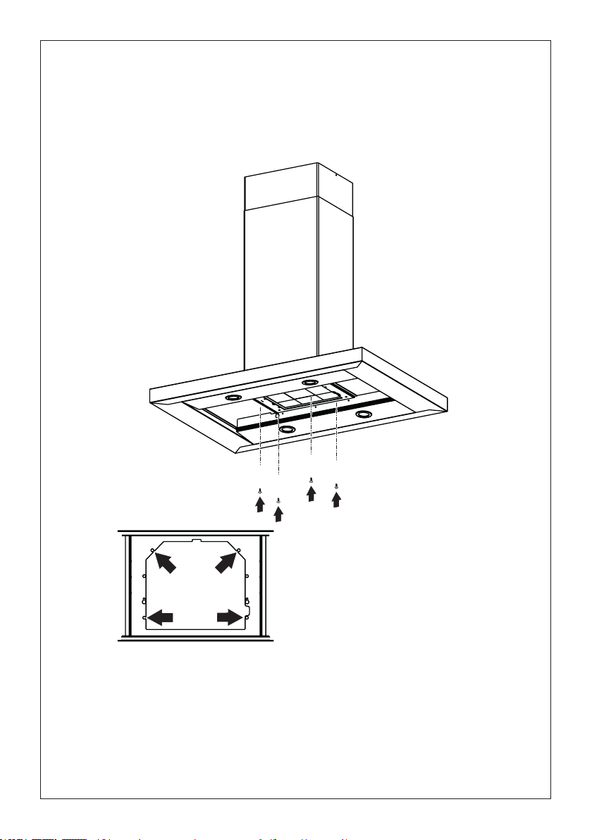
52
13
Retirelosltrosdegrasadelacapotadelacampana.
Retirecualquierltrodecarbónactivado.
Trabajandodesdeabajo,jelacapotadelacampanaalbastidordondeseindica,usandolos4tornillos
12q,luegoaprietetodoslostornillosconrmeza.
Fijación de la capota de la campana
I
I
T[
[
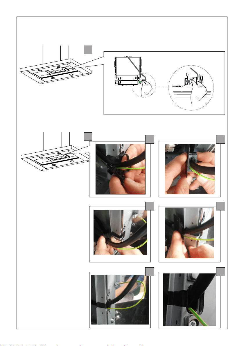
53
1
2
14
a
c
e
b
d
f
Fijeelcableenel
espacioindicado
concabledejación
delcomponente11,
comosemuestra,sin
tensarelcableado,
incluyendola
conexióndetierra.
Conecteelconectordelcabledel
cuerpodelacampanaalventilador
comosemuestra.
Realice la conexión eléctrica interna
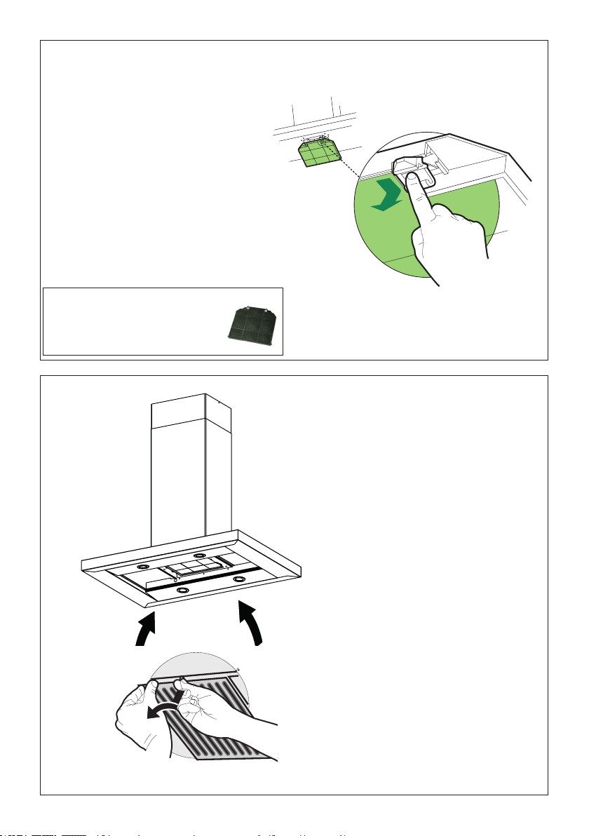
54
15
Attach a
charcoal
lterinthe
correct
positionand
blockitby
thexing
hooksas
shown.
Unlockthexinghooks(towardsthebackofthe
inserthood)toremove.
16
Para la opción de recirculación
sin conducto
Retirelosltrosdegrasa
metallicos de la capota de la
campana.
Serequiereaccesoriodeltrode
carbónactivado-Parte#-FILTER2
(secompraporseparado)

55
INFORMACIÓN DE USO Y CUIDADO
T1 T2 T3 T4 L
LT1 T2 T3 T4
Para mejores resultados
Enciendalacampanavariosminutosantesdecocinarparadesarrollarunujodeaireade-
cuado.Dejequelacampanafuncionedurantevariosminutosdespuésdequesecomplete
lacocciónparaeliminartodoelhumoylosoloresdelacocina.
T1.Botóndeapagadodelventilador:apagaelventilador.Elventiladorsepuedeoperarpresionando
cualquieradelosbotonesdeajustedelventilador.
Mantengapresionadoestebotóndurante2segundosparaactivarlafuncióndelayoff(desactivación
retardada),quemantendráelventiladorencendidodurante15minutosyseapagaráautomáticam-
ente.
T2.Botonesdeajustedelventilador:velocidadbaja.
T3.Botonesdeajustedelventilador:velocidadmedia.
T4.Botonesdeajustedelventilador:velocidadalta/velocidadintensiva.
Mantengapresionadoelbotóndurante2segundosparaactivarlavelocidadintensiva,queestá
programadaparaejecutarsedurante6minutos.Alnaldeestetiempo,volveráautomáticamente
alavelocidadestablecidaanteriormente.Adecuadoparatratarconnivelesmáximosdehumosde
cocina.
L.Botóndeluz:interruptordeencendido/apagadodelasluces.
NOTA:SisuproductohatenidounajustedeCFM,consulteelmanualdeajustedeCFMparaobtener
información.Algunasvelocidadesdelmotordefuncionespuedenserreducidas.
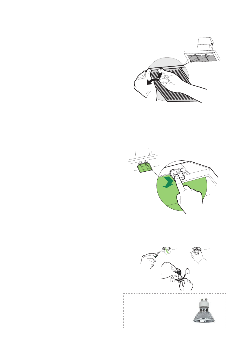
56
Limpiezadelosltrosdegrasametálicos
Losltrossedebenlimpiarcada2mesesdefuncionamiento,
o con mayor frecuencia con uso intensivo, y se puede lavar
en un lavavajillas.
• Quitarunltroalavez,tirarygirarlamanillaensentido
contrario a las agujas del reloj.
• Lavelosltrossin doblarlosydéjelossecarcomple-
tamenteantesdevolveracolocarlos.(Silasupercie
delltrocambiadecoloramedidaquepasaeltiempo,
estonotendráningúnefectoenlaecaciadelltro).
• Volver a montarla siguiendo la secuencia al contrario
teniendo cuidado de que la manilla quede hacia la parte
exterior.
• Asegúrese de eliminar toda el agua y cualquier otro
líquido antes de volver a instalar los ltros después
de la limpieza.
Reemplazodelltrodecarbónactivado
Elltronoeslavable,nopuedeserregenerado,ydebe
ser reemplazado aproximadamente cada 4 meses de
operación, o más frecuentemente con uso intensivo.
• Retirelosltrosdeaunoporvez,empujándoloshacia
la parte posterior de la unidad y al mismo tiempo tirando
hacia abajo.
• Retireelltrodecarbónsaturadoliberandolosganchos
dejación.
• Coloqueelnuevoltroyajústeloensuposicióncorrecta.
• Reemplace, teniendo cuidado de asegurarse de que la
manija mire hacia adelante.
Precaución:"Cuandoseusaenelmodode
recirculación,parareducirelriesgodeincendioy
descarga,utiliceúnicamenteelkitdeconversión
ModeloFILTER2".
LámparasLEDcon
autoglasamientoGu10-
enumeradasdeacuerdo
conul1993/nmx-j-578/1-
ance/csac22.2No.1993
Unidad de iluminación
• Quitelacubiertadelalámparaapresiónalpresio-
narladesdedebajodelanillometálico,sujetándola
conunamano.
• Reemplacelalámparaporunanuevadelmismo
tipo,asegurándosedeinsertarlasdosclavijasco-
rrectamenteenlosalojamientosdelportalámparas.
• Reemplacelacubiertadelalámparaapresión.

57
Diagrama de cableado
991.0530.011 H90-503
D00004494_00
991.0530.011 H90-503
D00004494_00
120V60Hz
58
Esta garantia Aplica para USA y Canada
January 4, 2016
FABER CONSUMER WARRANTY & SERVICE
All Faber products are warranted against any defect in materials or workmanship for the original purchaser
for a period of 1 year from the date of original purchase (requires proof of purchase). This warranty covers
labor and replacement parts. Faber, at its option, may repair or replace the product or components
necessary to restore the product to good working condition. To obtain warranty service, contact the dealer
from whom you purchased the range hood, or the local Faber distributor. If you cannot identify a local Faber
distributor, contact us at (508) 358-5353 for the name of a distributor in your area.
The following is not covered by Faber's warranty:
1. Service calls to correct the installation of your range hood, to instruct you how to use your range hood, to
replace or repair house fuses or to correct house wiring or plumbing.
2. Service calls to repair or replace range hood light bulbs, fuses or filters. Those consumable parts are
excluded from warranty coverage.
3. Repairs when your range hood is used for other than normal, single-family household use.
4. Damage resulting from accident, alteration, misuse, abuse, fire, flood, acts of God, improper installation,
installation not in accordance with electrical or plumbing codes or Faber documentation, or use of products
not approved by Faber.
5. Replacement parts or repair labor costs for units operated outside the United States or Canada, including
any non-UL or C-UL approved Faber range hoods.
6. Repairs to the hood resulting from unauthorized modifications made to the range hood.
7. Expenses for travel and transportation for product service in remote locations and pickup and delivery
charges. Faber range hoods should be serviced in the home.
THIS WARRANTY DOES NOT ALLOW RECOVERY OF INCIDENTAL OR CONSEQUENTIAL DAMAGES, INCLUDING, WITHOUT
LIMITATION, DIRECT, INDIRECT, INCIDENTAL, SPECIAL OR CONSEQUENTIAL DAMAGES, PERSONAL INJURY/WRONGFUL
DEATH OR LOST PROFITS FABER WARRANTY IS LIMITED TO THE ABOVE CONDITIONS AND TO THE WARRANTY PERIOD
SPECIFIED HEREIN AND IS EXCLUSIVE. EXCEPT AS EXPRESSLY SPECIFIED IN THIS AGREEMENT, FABER DISCLAIMS ALL
EXPRESS OR IMPLIED CONDITIONS, REPRESENTATIONS, AND WARRANTIES INCLUDING, WITHOUT LIMITATION, ANY
IMPLIED WARRANTIES OF MERCHANTABILITY OR FITNESS FOR A PARTICULAR PURPOSE
.
This warranty gives you specific legal rights that may vary from state to state.
Model#: ______________________________ Serial #: _____________________________
GARANTÍAYSERVICIOALCONSUMIDORFABER
TodoslosproductosFaberestángarantizadoscontracualquierdefectodematerialesomanodeobraparael
compradororiginalporunperíodode1añoapartirdelafechadecompraoriginal(requierepruebadecompra).
Estagarantíacubremanodeobraypiezasderepuesto.Faber,asuelección,puederepararoreemplazarel
productoocomponentesnecesariospararestaurarelproductoenbuenascondicionesdetrabajo.Paraobtener
elserviciodegarantía,póngaseencontactoconeldistribuidordequienadquiriólacampanaextractoraoconel
distribuidorlocaldeFaber.SinopuedeidenticaraundistribuidorlocaldeFaber,comuníqueseconnosotrosal
(508)358-5353paraobtenerelnombredeundistribuidorensuárea.
Lo siguiente no está cubierto por la garantía de Faber:
1. Llamadasdeservicioparacorregirlainstalacióndesucampanaextractora,parainstruirlesobrecómousarsu
campanaextractora,parareemplazarorepararfusiblesdelacasaoparacorregirelcableadodelacasaola
plomería.
2. Llamadasdeserviciopararepararoreemplazarlasbombillas,fusiblesoltrosdelacampanaextractora.Estas
partesdeconsumiblesestánexcluidasdelacoberturadelagarantía.
3. Reparaciones,cuandosucampanaextractoraseutilizaparausodomésticodistintoalnormal.
4. Dañosresultantesdeaccidente,alteración,maluso,abuso,incendio,inundación,eventosnaturales,instala-
ciónincorrecta,instalaciónnoconformealoscódigoseléctricosodeplomeríaoladocumentacióndeFaber,o
usodeproductosnoaprobadosporFaber.
5. PiezasderepuestoocostosdemanodeobradereparaciónparaunidadesoperadasfueradelosEstados
UnidosoCanadá,incluyendocualquiercampanadecocinaFabernoaprobadaporULoC-UL.
6. Reparacionesalacampanaresultantesdemodicacionesnoautorizadasalamisma.
7. Gastosdeviajeytransporteparaelserviciodelproductoenlugaresremotos,ygastosderecogidayentrega.
LascampanasdecocinaFaberdebenserreparadasenelhogar.
ESTAGARANTÍANOPERMITELARECUPERACIÓNDEDAÑOSINCIDENTALESOCONSECUENTES,IN-
CLUYENDO,SINLIMITACIÓN,DAÑOSDIRECTOS,INDIRECTOS,INCIDENTALES,ESPECIALESOCONSE-
CUENTES,LESIONESPERSONALESOMUERTEINCORRECTAOBENEFICIOSPERDIDOS.LAGARANTÍA
DEFABERSELIMITAALASCONDICIONESANTERIORESYALPERÍODODEGARANTÍAESPECIFICADO
AQUÍYESEXCLUSIVA.EXCEPTODADOLOEXPRESAMENTEESPECIFICADOENESTEACUERDO,FABER
RENUNCIAATODASLASCONDICIONES,REPRESENTACIONESYGARANTÍASEXPRESASOIMPLÍCITAS
INCLUYENDO,SINLIMITACIÓN,CUALQUIERGARANTÍAIMPLÍCITADECOMERCIABILIDADOADECUACIÓN
PARAUNPROPÓSITOPARTICULAR.
Estagarantíaleotorgaderechoslegalesespecícosquepuedenvariardeestadoaestado.
Modelo:____________________________Númerodeserie____________________________
4deenerode2016

59

991.0568.764_01-181121
D00005441_00