OPERATOR'S MANUAL
MODEL #18029
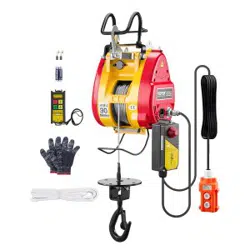
WINCH WIRELESS REMOTE KIT
or visit championpowerequipment.com
READ AND SAVE THIS MANUAL. This manual contains important safety precautions which should be read
and understood before operating the product. Failure to do so could result in serious injury. This manual should
remain with the product.
Specifications, descriptions and illustrations in this manual are as accurate as known at the time of publication,
but are subject to change without notice.
Champion Power Equipment, Inc.
ACTIVATE YOUR WARRANTY
by registering your product:
championpowerequipment.com
SERIAL NO.
REV 20240724

18029 - WINCH WIRELESS REMOTE KIT
TABLE OF CONTENTS
2
TABLE OF CONTENTS
Introduction
................................. 3
Safety Definitions .......................... 3
Controls and Features .....................4
Winch Wireless Remote Kit ....................... 4
Assembly .................................... 5
1) Install Solenoid/Contactor ..................... 5
2) Install Rocker Switch .......................... 5
3) Adding/Replacing the remote batteries .......... 5
4) Wiring the Winch ............................. 5
5) Install the Antenna ............................ 6
6) Test Winch Operation ......................... 6
Solenoid/Contactor Wiring Diagram ............... 7
Antenna Wiring Diagram ......................... 8

18029 - WINCH WIRELESS REMOTE KIT
INTRODUCTION
3
INTRODUCTION
Congratulations on your purchase of a Champion Power
Equipment (CPE) product. CPE designs, builds, and
supports all of our products to strict specifications and
guidelines. With proper product knowledge, safe use, and
regular maintenance, this product should bring years of
satisfying service.
Every effort has been made to ensure the accuracy and
completeness of the information in this manual at the
time of publication, and we reserve the right to change,
alter and/or improve the product and this document at
any time without prior notice.
Since CPE highly values how our products are designed,
manufactured, operated and are serviced, and also highly
value your safety and the safety of others, we would
like you to take the time to review this product manual
and other product materials thoroughly and be fully
aware and knowledgeable of the assembly, operation,
dangers and maintenance of the product before use. Fully
familiarize yourself, and make sure others who plan on
operating the product fully familiarize themselves too,
with the proper safety and operation procedures before
each use. Please always exercise common sense and
always err on the side of caution when operating the
product to ensure no accident, property damage, or injury
occurs. We want you to continue to use and be satisfied
with your CPE product for years to come.
When contacting CPE about parts and/or service, you will
need to supply the complete model and serial numbers
of your product. Transcribe the information found on your
product’s nameplate label to the table below
CPE TECHNICAL SUPPORT TEAM
1-877-338-0999
MODEL NUMBER
18029
SERIAL NUMBER
DATE OF PURCHASE
PURCHASE LOCATION
SAFETY DEFINITIONS
The purpose of safety symbols is to attract your
attention to possible dangers. The safety symbols, and
their explanations, deserve your careful attention and
understanding. The safety warnings do not by themselves
eliminate any danger. The instructions or warnings they
give are not substitutes for proper accident prevention
measures.
DANGER
DANGER indicates a hazardous situation which,if not
avoided, will result in death or serious injury.
WARNING
WARNING indicates a hazardous situation which, if not
avoided, could result in death or serious injury.
CAUTION
CAUTION indicates a hazardous situation which, if not
avoided, could result in minor or moderate injury.
NOTICE
NOTICE indicates information considered important,
but not hazard-related (e.g., messages relating to
property damage).
WARNING
Cancer and Reproductive Harm –
www.P65Warnings.ca.gov
18029 - WINCH WIRELESS REMOTE KIT
CONTROLS AND FEATURES
4
OUT
SORTIE
IN
ENTRÉE
POWER
ALIMENTATION
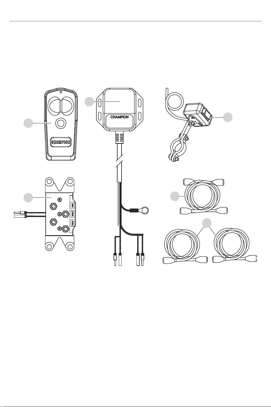
CONTROLS AND FEATURES
Read this operator’s manual before operating your winch. Familiarize yourself with the location and function of the
controls and features. Save this manual for future reference.
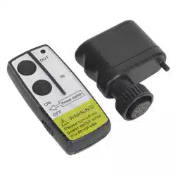
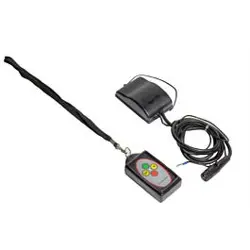
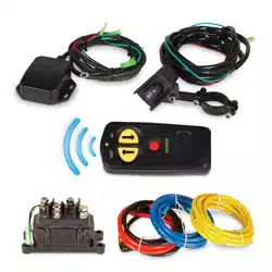
Winch Wireless Remote Kit
* Mounting hardware not shown.
1. Wireless Remote Control – Used to power the
rope in or out of your winch drum.
2. Antenna – Receives wireless signal from wireless
remote control from within a 50 ft. radius.
3. Rocker Switch – Rocker switch with handlebar
mount for powering the rope in or out of your winch
drum.
4. Solenoid/Contactor – Power from the vehicle
battery flows through the weather sealed solenoid/
contactor switch before being directed to the winch
motor.
5. Battery Connection Cables – Used to connect the
battery to the solenoid/contactor.
6. Winch Connection Cables – Used to connect the
winch motor to the solenoid/contactor.
1
4
5
3
6
2

18029 - WINCH WIRELESS REMOTE KIT
ASSEMBLY
5
ASSEMBLY
1) Install Solenoid/Contactor
Find a location for the contactor. If the model specific
mounting kit does not indicate a recommended contactor
location, then it is recommended that the contactor be
mounted close to the battery in a clean dry location.
Make sure the location you chose allows sufficient
clearance from all metal components. Drill mounting
holes if required. Once location is found do not install
until all wiring is completed.
2) Install Rocker Switch
1. Decide which handlebar the switch will be mounted
on. The switch is usually installed on the left
handlebar.
2. Use a piece of electrical tape around the handlebar
to help prevent rotation of the mount on the
handlebar. Do NOT tighten over any hoses or
cables.
3. Once your switch is mounted you can route the
wires back to where your contactor is located.
4. Splice the end of the RED wire to an ignition
(keyed) controlled power source using the supplied
wire tap. You may need to use a test light to locate
a suitable wire. The wire should only have power
when the key is in the ON position.
5. Make sure the handlebars have full range of
motion and then secure the switch’s cable with the
supplied cable ties.
NOTICE
– Always purchase the correct size and grade of
battery most suitable for the intended use.
– Clean the battery contacts and also those of the
device prior to battery installation.
– Remove batteries from equipment which is not to
be used for an extended period of time.
– Remove batteries if consumed or if product is to
be left unused for a long time.
3) Adding/Replacing the remote
batteries
1. Remove two screws with a Phillips screwdriver (not
included) by turning counter clockwise.
2. Disassemble the two halves of the remote apart
slightly by hand.
3. Remove the key ring.
4. First use: insert (2) A23 batteries included.
Replacement: carefully remove the older batteries
and insert the new (2) A23 batteries.
5. Reverse the above instructions to reassemble the
remote.
4) Wiring the Winch
CAUTION
Never route electrical cables across any sharp edges,
through or near moving parts, or near parts that
become hot.
1. Connect the yellow and blue cables to the motor
terminals on the winch. Torque the terminal nuts
on the motor to 5.7 N-m (50 lb-in). Route the other
ends to the contactor location.
2. Connect the yellow and blue cables to the contactor
(yellow to yellow and blue to blue). Do NOT tighten
nuts.
3. Connect the red and black cables to your contactor
(red to red and black to black). Do NOT tighten
nuts. Route the other ends to your battery location.
CAUTION
Battery cables should not be drawn taut. Leave some
slack for cable movement.
4. Connect the rocker switch to the contactor (black
to black and green to green).
5. Once all wiring is connected to the contactor you
can then mount it using the supplied M6 hardware.
6. Torque the contactor terminal nuts to 4.5 N-m
(40 lb-in). Do NOT over tighten.
7. Place all terminal boots over terminals and secure
all cables with cable ties or electrical tape (not
included).

18029 - WINCH WIRELESS REMOTE KIT
ASSEMBLY
6
8. Connect the battery leads from the contactor to the
ATV’s Battery (red to red and black to black).
NOTICE
Depending on the location of the contactor, you may
need to use the black and red cables in place of the
yellow and blue, and the yellow and blue in place
of the red and black. Just remember that this also
changes the diagram.
5) Install the Antenna
1. Determine the mounting location.
2. If mounting on a flat surface, mark and drill a
minimum of two (2) mounting holes, one on each
side of the antenna. Loosely attach the antenna
using the supplied bolts and lock nuts. Do NOT
tighten fasteners at this time.
3. If mounting on a frame tube, loosely attach using
the supplied cable ties.
4. Locate the black and green wires running from
the contactor to the rocker switch. Find the bullet
connectors on these wires located near the
contactor.
5. Plan a route for the wire harness between the
antenna and these bullet connectors.
6. Pull apart the bullet connectors on the BLACK and
GREEN wires identified in step 4 above. These will
be located near the contactor
7. Connect the rocker switch and contactor to the
antenna (black to black and green to green).
8. Connect the black ground wire with the ring to the
black (–) terminal on the solenoid/contactor.
6) Test Winch Operation
1. Make sure there are no exposed terminals or
wiring, and wiring to all components is correct, all
loose wires are secured.
2. Turn ATV ignition switch to the ON position.
3. Check the winch for proper operation using the
rocker switch. The wire rope should spool in and
out in the direction indicated on the switch.
4. To use test wireless system, activate the system
by pressing and holding the POWER button on
the wireless remote for 3 seconds. This transfers
control of the winch to the wireless control system.
A red indicator light on the wireless remote turns on
when the system is active and ready to use.
NOTICE
LED Indicator Light
– Steady Red: System active and ready to use.
– Flashing Red: Winch powering in or out.
5. Verify that the winch spools the rope in and out
properly by pressing the buttons on the wireless
remote. The wire rope should spool in and out in
the direction indicated on the remote.
6. Deactivate the system by pressing the POWER
button on the wireless remote and holding for 3
seconds, until red light turns off or after 2 mins of
idle time, the wireless system de-activates.
WARNING
This kit is designed for use on front mounted self-
recovery winches only. The remote is not designed
for and should not be used on winches or hoists in
industrial applications (car haulers/carriers, wrecker,
cranes, etc.) or for any other remote controlled
applications.
18029 - WINCH WIRELESS REMOTE KIT
ASSEMBLY
7
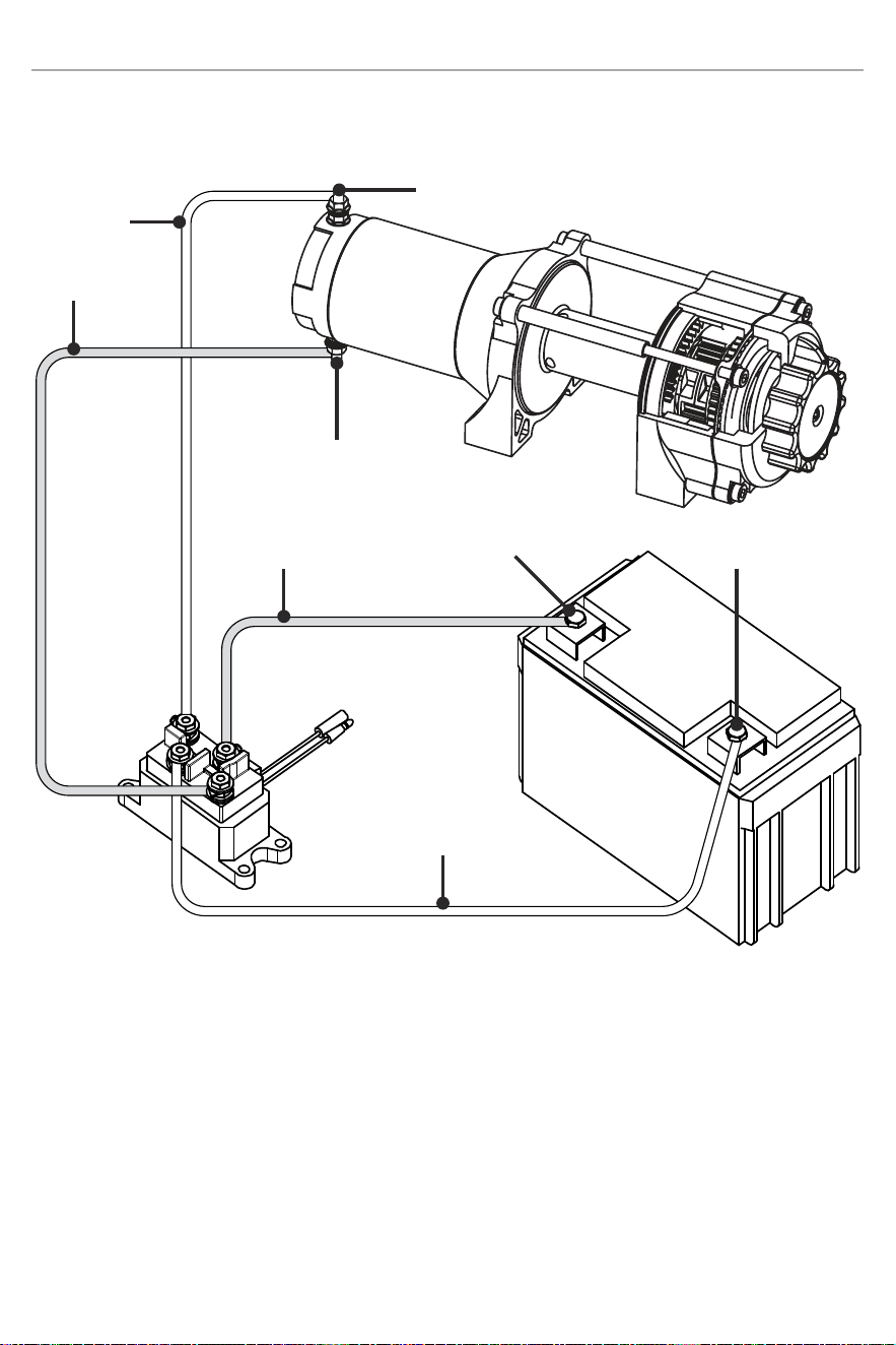
Solenoid/Contactor Wiring Diagram
Negative (–)
Positive (+)
Negative (–)
Blue
Positive (+)
Yellow
Red
Black
To Switch And
Remote Wiring
18029 - WINCH WIRELESS REMOTE KIT
ASSEMBLY
8
OUT
SORTIE
IN
ENTRÉE
POWER
ALIMENTATION
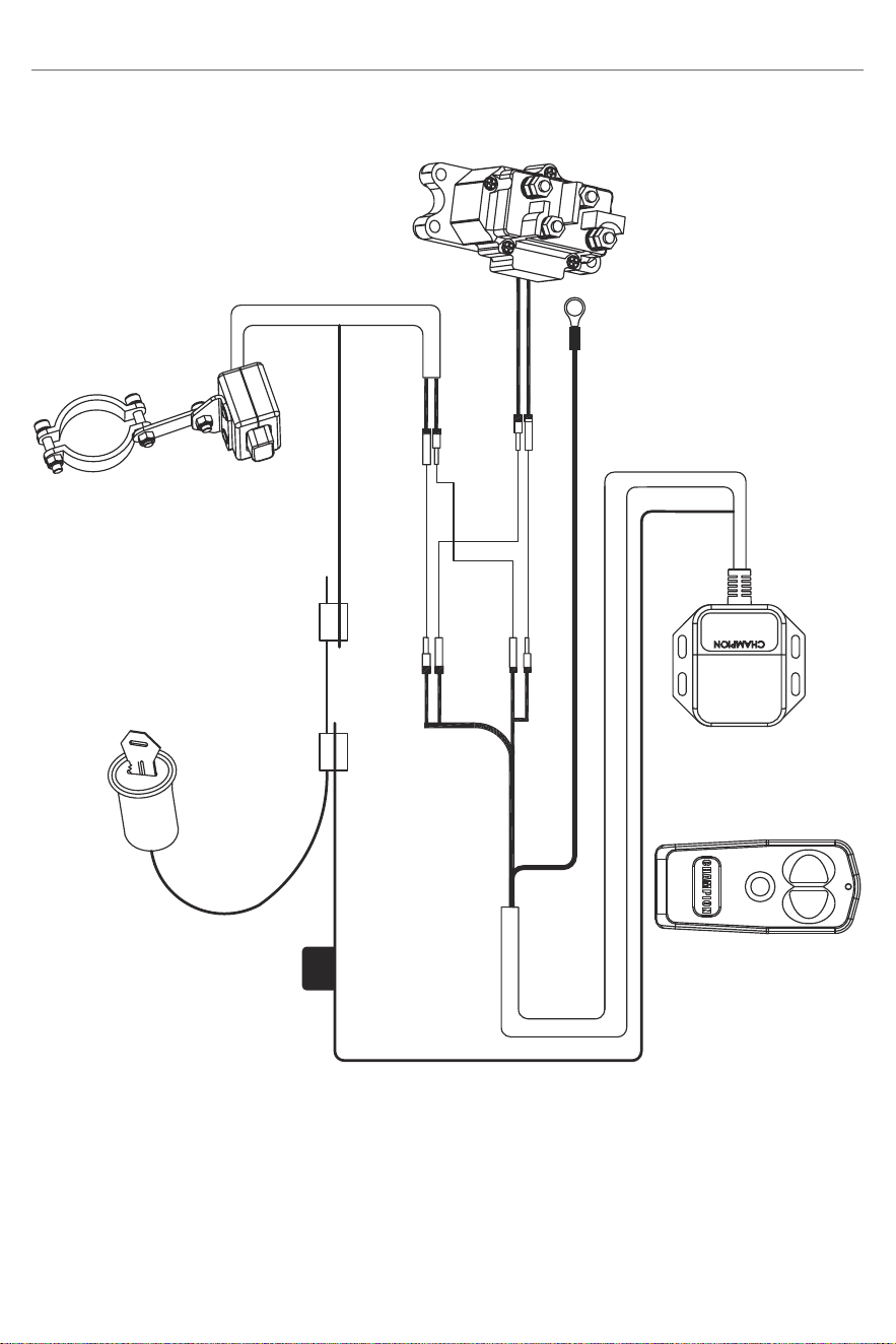
Antenna Wiring Diagram
Red
Black
Green
Green
Green
Black & White
Black
Ignition
Wire
Red
7.5 Amp
Fuse
To Ground on Solenoid/Contactor

WARRANTY*
CHAMPION POWER EQUIPMENT
1 YEAR LIMITED WARRANTY
Warranty Qualifications
To register your product for warranty and FREE lifetime
call center technical support please visit:
https://www.championpowerequipment.com/register
To complete registration you will need to include a copy
of the purchase receipt as proof of original purchase.
Proof of purchase is required for warranty service.
Please register within ten (10) days from date of
purchase.
Repair/Replacement Warranty
CPE warrants to the original purchaser that the
mechanical and electrical components will be free of
defects in material and workmanship for a period of
one year (parts and labor) from the original date of
purchase and 90 days (parts and labor) for commercial
and industrial use. Transportation charges on product
submitted for repair or replacement under this warranty
are the sole responsibility of the purchaser. This
warranty only applies to the original purchaser and is not
transferable.
Do Not Return The Unit To The Place
Of Purchase
Contact CPE’s Technical Service and CPE will
troubleshoot any issue via phone or e-mail. If the
problem is not corrected by this method, CPE will, at its
option, authorize evaluation, repair or replacement of the
defective part or component at a CPE Service Center.
CPE will provide you with a case number for warranty
service. Please keep it for future reference. Repairs
or replacements without prior authorization, or at an
unauthorized repair facility, will not be covered by this
warranty.
Warranty Exclusions
This warranty does not cover the following repairs and
equipment:
Normal Wear
Products with mechanical and electrical components
need periodic parts and service to perform well. This
warranty does not cover repair when normal use has
exhausted the life of a part or the equipment as a whole.
Installation, Use and Maintenance
This warranty will not apply to parts and/or labor if the
product is deemed to have been misused, neglected,
involved in an accident, abused, loaded beyond the
product’s limits, modified, installed improperly or
connected incorrectly to any electrical component.
Normal maintenance is not covered by this warranty
and is not required to be performed at a facility or by a
person authorized by CPE.
Other Exclusions
This warranty excludes:
– Cosmetic defects such as paint, decals, etc.
– Wear items such as filter elements, o-rings, etc.
– Accessory parts such as starting batteries, and
storage covers.
– Failures due to acts of God and other force majeure
events beyond the manufacturer’s control.
– Problems caused by parts that are not original
Champion Power Equipment parts.
Limits of Implied Warranty and
Consequential Damage
Champion Power Equipment disclaims any obligation to
cover any loss of time, use of this product, freight, or any
incidental or consequential claim by anyone from using
this product. THIS WARRANTY IS IN LIEU OF ALL OTHER
WARRANTIES, EXPRESS OR IMPLIED, INCLUDING
WARRANTIES OF MERCHANTABILITY OR FITNESS FOR
A PARTICULAR PURPOSE.
A unit provided as an exchange will be subject to the
warranty of the original unit. The length of the warranty
governing the exchanged unit will remain calculated by
reference to the purchase date of the original unit.
This warranty gives you certain legal rights which may
change from state to state or province to province. Your
state or province may also have other rights you may be
entitled to that are not listed within this warranty.
Contact Information
Address
Champion Power Equipment, Inc.
6370 S Pioneer Way, Unit 101
Las Vegas, NV 89113 USA
www.championpowerequipment.com
Customer Service
Toll Free: 1-877-338-0999
info@championpowerequipment.com
Fax no.: 1-562-236-9429
Technical Service
Toll Free: 1-877-338-0999
tech@championpowerequipment.com
24/7 Tech Support: 1-562-204-1188