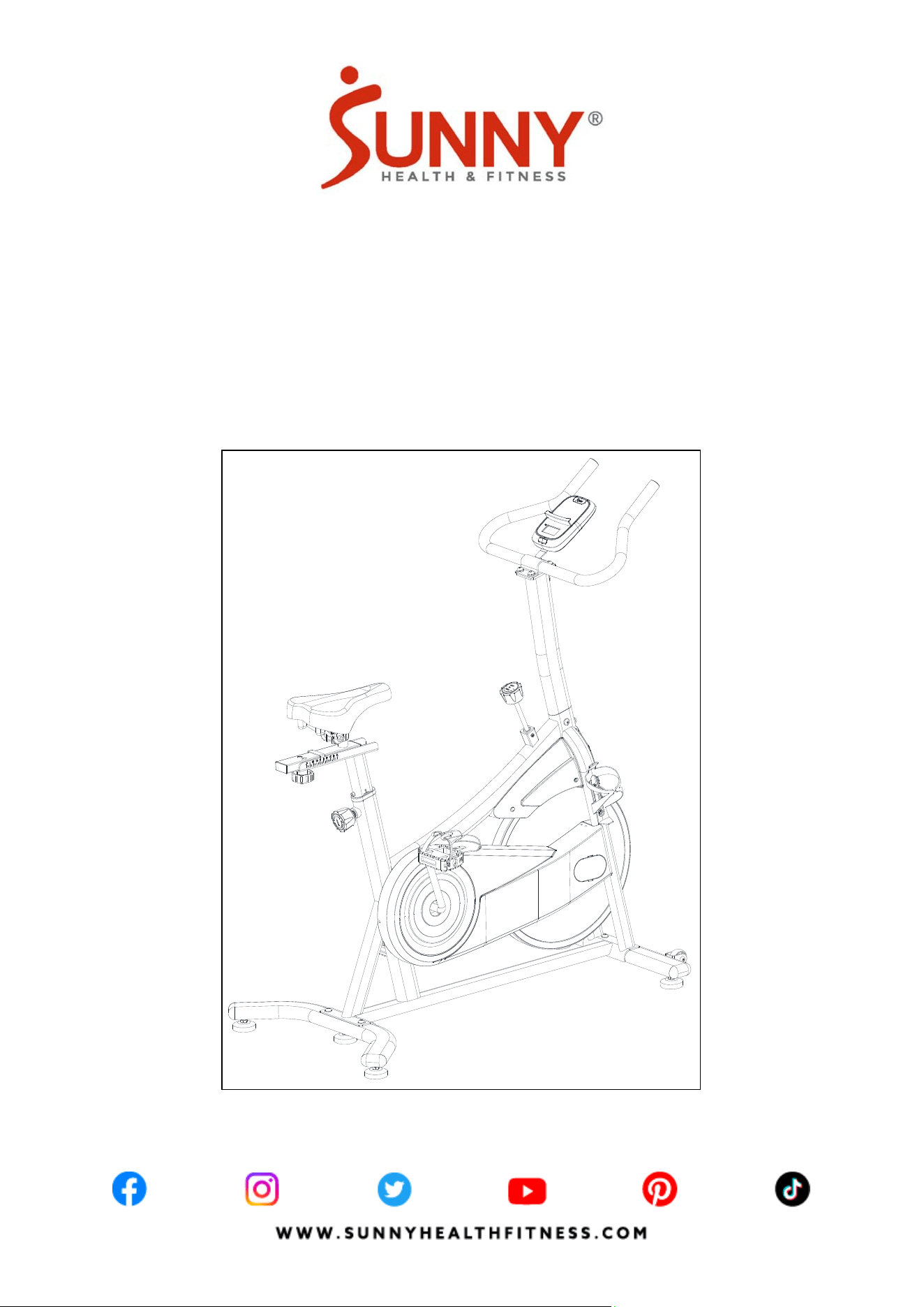
ACTIVE 100 SMART MAGNETIC
CYCLING EXERCISE BIKE
SF-B124066
USER MANUAL
IMPORTANT! Please retain owner’s manual for maintenance and adjustment instructions. Your
satisfaction is very important to us, PLEASE DO NOT RETURN UNTIL YOU HAVE CONTACTED
US: [email protected] or 1- 877 - 90SUNNY (877-907-8669).

1
IMPORTANT SAFETY INFORMATION
We thank you for choosing our product. To ensure your safety and health, please use this
equipment correctly. It is important to read this entire manual before assembling and using the
equipment. Safe and effective use can only be achieved if the equipment is assembled, maintained,
and used properly. It is your responsibility to ensure that all users of the equipment are informed of
all warnings and precautions.
1. Before starting any exercise program, you should consult your physician to determine if you
have any medical or physical condition that could put your health and safety at risk or prevent
you from using the equipment properly. Your physician’s advice is essential if you are taking
medication that affects your heart rate, blood pressure or cholesterol level.
2. Be aware of your body’s signals. Incorrect or excessive exercise can damage your health. Stop
exercising if you experience any of the following symptoms: pain, tightness in your chest,
irregular heartbeat, shortness of breath, lightheadedness, dizziness, or feelings of nausea. If
you do experience any of these conditions, you should consult your physician before continuing
with your exercise program.
3. Keep children and pets away from the equipment. The equipment is designed for adult use
only.
4. Use the equipment on a solid, flat level surface with a protective cover for your floor or carpet.
To ensure safety, the equipment should have at least 2 feet (60 cm) of free space all around it.
5. Ensure that all nuts and bolts are securely tightened before using the equipment. The safety of
the equipment can only be maintained if it is regularly examined for damage and/or wear and
tear.
6. Always use the equipment as indicated. If you find any defective components while assembling
or checking the equipment, or if you hear any unusual noises coming from the equipment
during exercise, discontinue use of the equipment immediately and do not use until the problem
has been rectified.
7. Wear suitable clothing while using the equipment. Avoid wearing loose clothing that may
become entangled in the equipment.
8. Do not place fingers or objects into the moving parts of the equipment.
9. The maximum weight capacity of this unit is 265 lbs (120kg).
10. The equipment is not suitable for therapeutic use.
11. To avoid bodily injury and/or damage to the product or property, proper lifting and moving are
required.
12. Your product is intended for use in cool and dry conditions. You should avoid storage in
extremely cold, hot or damp areas as this may lead to corrosion and other related problems.
13. This equipment is designed for indoor and home use only; it is not intended for commercial
use.
2
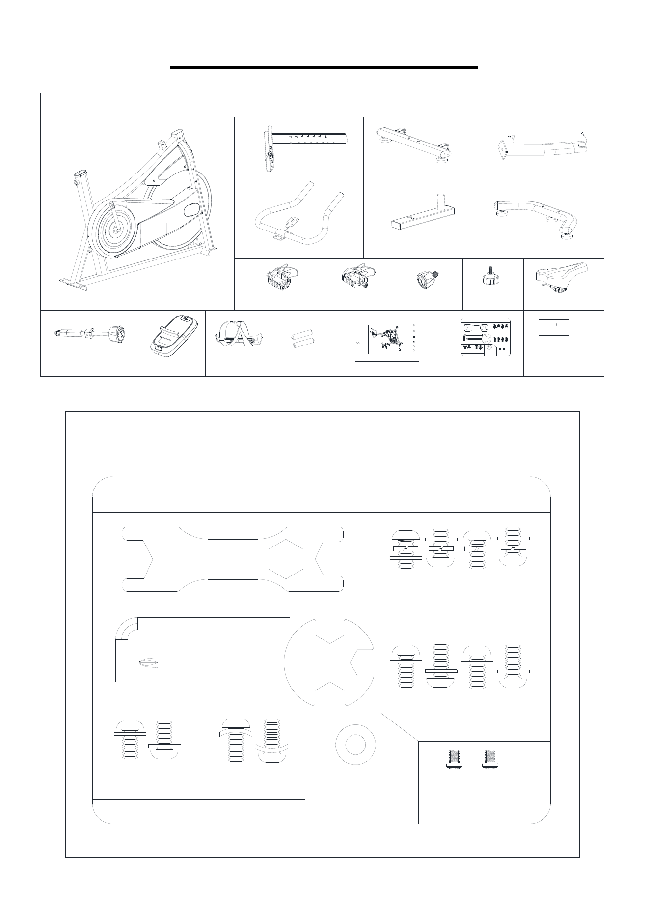
PRE-ASSEMBLY CHECK LIST
Before you start to assemble, please make sure all parts are included.
23
19
2
39
6
42
70
W W W.S U N N Y H E A L T H F I T N E S S.C O M
ACTIVE 100 SMART MAGNETIC
B
THANK
YOU
FOR YOUR PURCHASE
If yo u h ave a ny qu esti ons , ple ase con tact us at (877) 90SUNNY or
email: support@sunnyhealthfitness.com
UNNY
H E A L T H & F L T N E S S
36
MPORTANT! Please retai n own er’s manu al f or m aintenance and
adjustment instructions. Your satisfaction is very important to us,
PLEASE DO NOT RET URN UNTIL YOU HAVE CONTACTED US:
support@sunnyhealthfitness.com or 1- 877 - 90SUNNY (877-907-8669).
UNNY
H E A L T H & F L T N E S S
f
4
A
62
C
D
1
5
3
43
7
1
SF-B124066
USER MANUAL
CYCLING EXERCISE BIKE
3-5
#57 M8*10 2PCS
#9 Φ16*1.5 2PCS
3-1
SF-B124066 HARDWARE PACKAGE
#92 S13-S14-S15 1PC
#91 S6 1PC
#44 M5*6 2PCS
#40 Φ20*2 1PC
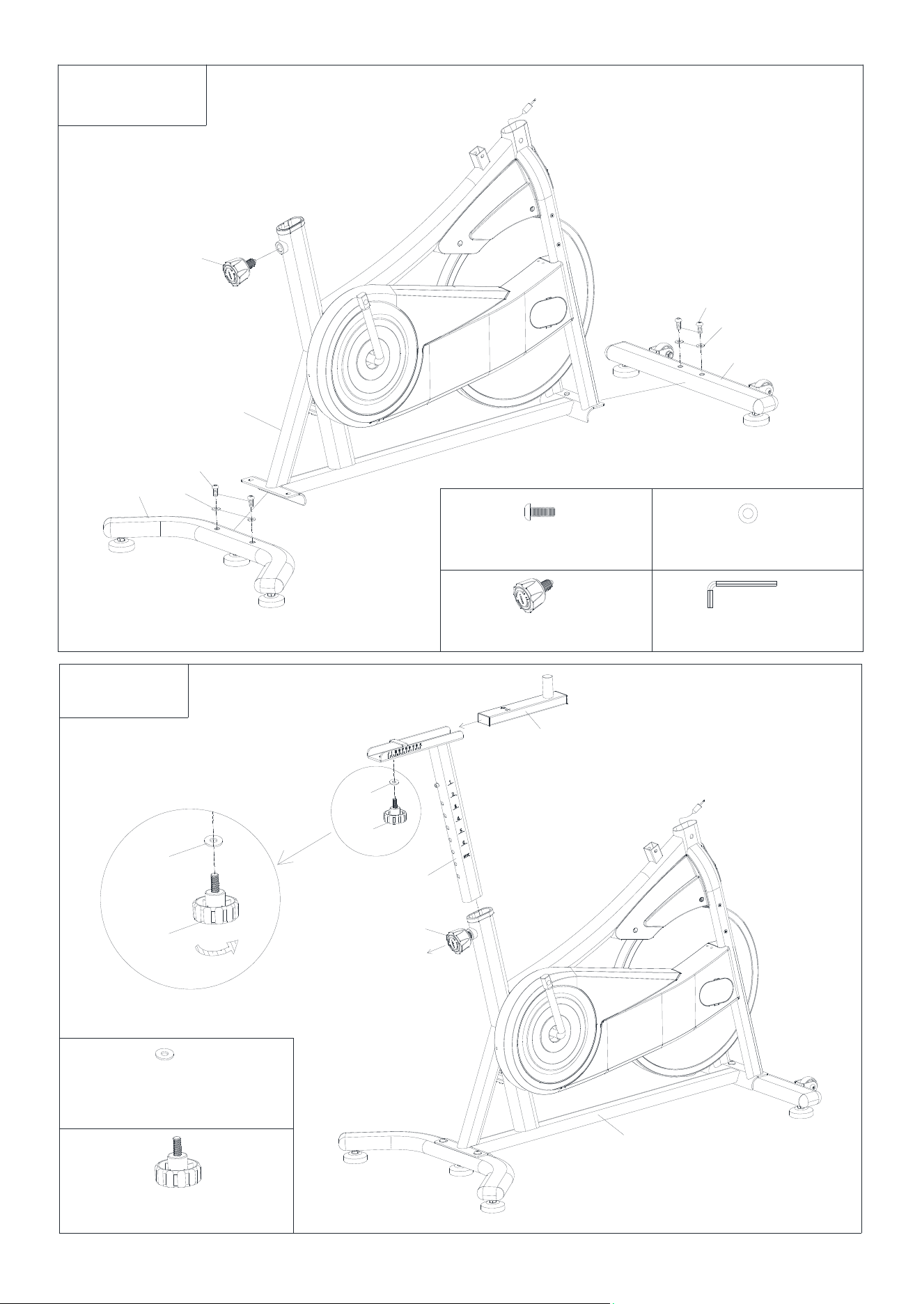
3-2
3-4
3-6
#90 S13-S17-S19 1PC
#58 M8*16 2PCS
#66 Φ16*1.5 2PCS
#8 M8*20 4PCS
#9 Φ16*1.5 4PCS
#58 M8*16 4PCS
#59 D8 4PCS
#9 Φ16*1.5 4PCS
3-4
3-6
3-5
#57 M8*10 2PCS
#9 Φ16*1.5 2PCS
3-1
SF-B124066 HARDWARE PACKAGE
#92 S13-S14-S15 1PC
#91 S6 1PC
#8 M8*20 4PCS
#9 Φ16*1.5 4PCS
#90 S13-S17-S19 1PC
#58 M8*16 2PCS
#66 Φ16*1.5 2PCS
#44 M5*6 2PCS
#40 Φ20*2 1PC
3-2
2
#58 M8*16 4PCS
#59 D8 4PCS
#9 Φ16*1.5 4PCS
3
#9 Φ16*1.5 4PCS
8
9
7
36
8
9
3
1
3-1
#91 S6 1PC
#8 M8*20 4PCS
#36 M16*1.5 1PC
3-2
39
40
6
36
1
#39 M8*20 1PC
#40 Φ20*2.0 1PC
2
39
40
4
3-3
23
18
70
14
21
19
1
92
23
92
19
71
S13
S14
S15
S17
S19
#90 S13-S17-S19 1PC
#14 M5*12 2PCS
#71 Φ10*1.2 2PCS
#92 S13-S14-S15 1PC
S13
5
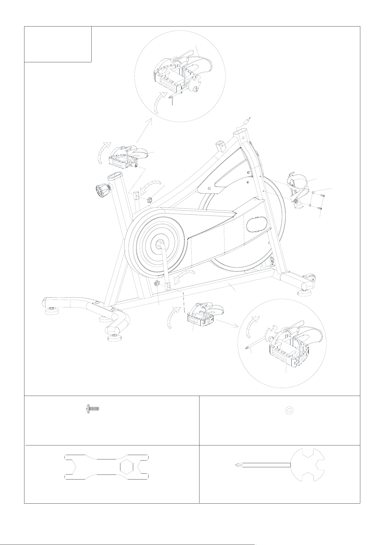
3-4
S13
S14
S15
#44 M5*6 2PCS
#92 S13-S14-S15 1PC
43
44
44
42
1
43
44
44
9
57
58
66
9
57
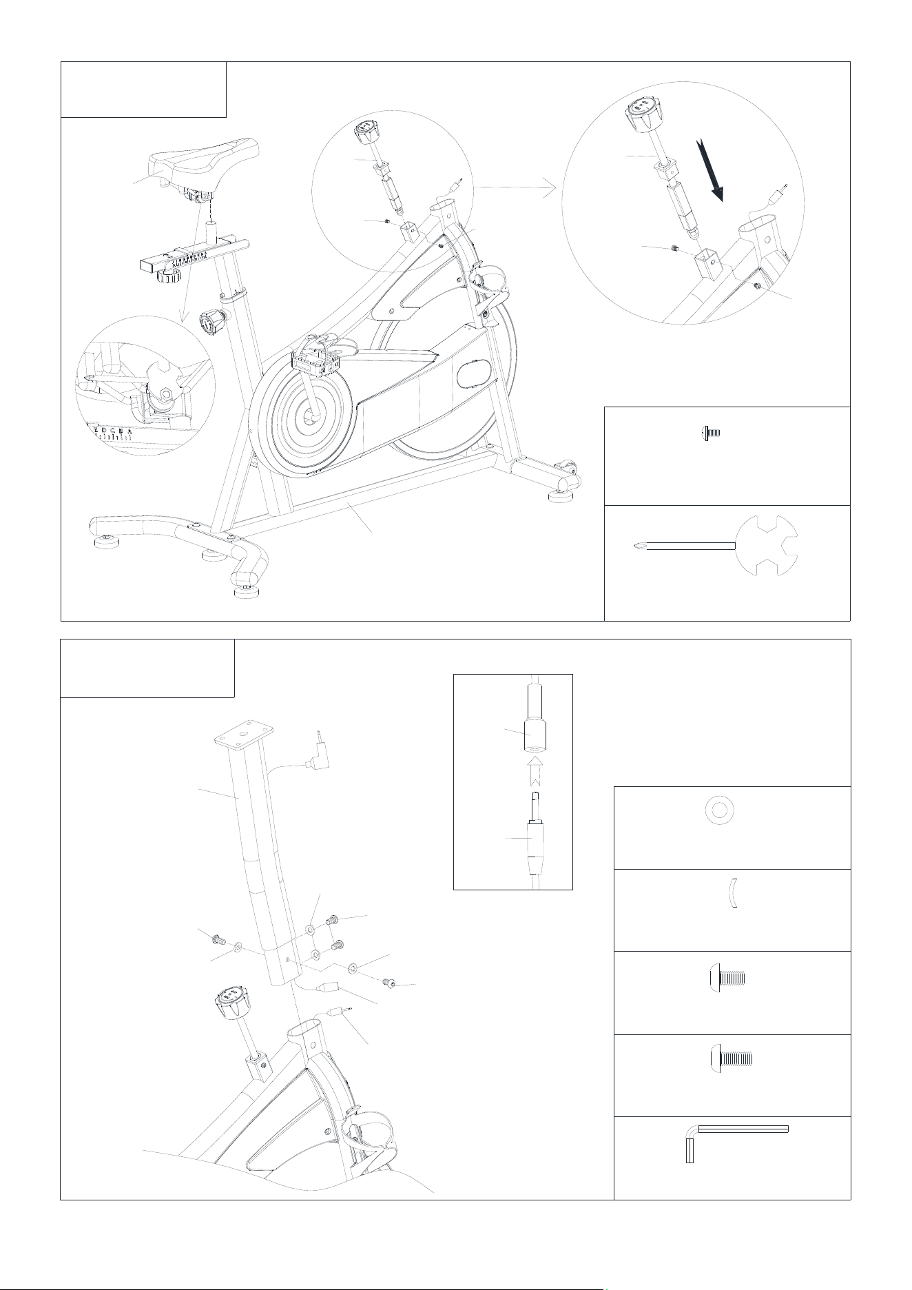
3-5
64
56
4
64
56
#57 M8*10 2PCS
#66 Φ16*1.5 2PCS
#9 Φ16*1.5 2PCS
#91 S6 1PC
#58 M8*16 2PCS
6
3-6
#91 S6 1PC
4
58
58
59
9
59
9
5
58
59
9
#58 M8*16 4PCS
#59 D8 4PCS
#9 Φ16*1.5 4PCS
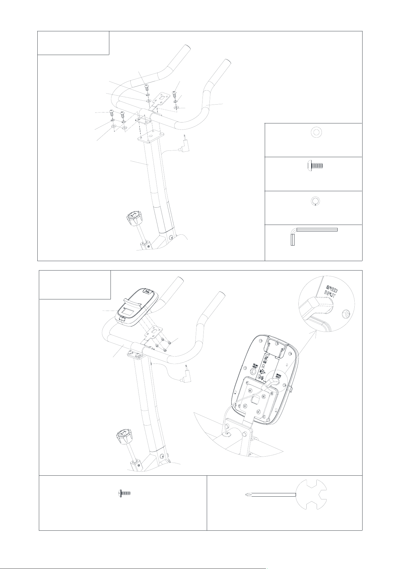
62
61
#61 M5*10 4PCS
S13
S14
S15
#92 S13-S14-S15 1PC
5
3-7
7
MAINTENANCE & ADJUSTMENT GUIDE
89
10
7
A
B
S13
S14
S15
#92 S13-S14-S15 1PC
S13
S14
S15
#92 S13-S14-S15 1PC
42
76
2
36
39
6
42
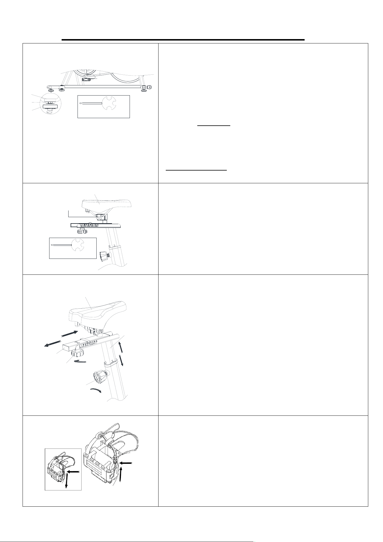
ADJUSTING THE HEIGHT AND BALANCE
In order to achieve a smooth and comfortable ride, you
must ensure that the stability of the bike is secured. If you
notice that the bike is unbalanced during use, you should
adjust the Foot Pads (No. 10) located beneath the Front
& Rear Stabilizers (No. 3 & No. 7) of the bike. To do so,
use Spanner (No. 92) to loosen Hex Nut (No. 89) by
turning it clockwise (direction B). With the Hex Nut (No.
89) loosened, rotate the Foot Pad (No. 10) until it sits
level with the surface that the bike is on. When you have
finished adjusting the Foot Pads (No. 10), use Spanner
(No. 92) to re-tighten the Hex Nut (No. 89) by turning it
counter-clockwise (direction A). If required, repeat this
p
rocess to ad
j
ust the remainin
g
Foot Pads
(
No. 10
)
.
ADJUSTING THE SADDLE
After adjusting the direction and angle of the Seat (No.
42), tighten and secure the Hex Nut (No. 76) to the Seat
(No. 42) with Spanner (No. 92).
ADJUSTING THE SEAT
The seat of this bike is fully adjustable as it moves Up,
Down, Fore (forward), Aft (backward).
To adjust the height of the Seat Post (No. 2), loosen and
pull the Adjustment Knob (No. 36) outward, then raise
or lower the Seat (No. 42) to the desired height. Once
adjusted, re-insert and tighten the Adjustment Knob
(No. 36) to secure the Seat Post (No. 2) in place.
To adjust the Seat (No. 42) back and forth, loosen the
Adjustment Knob (No. 39) then slide the Seat Slider
(No. 6) to the desired position. Once positioned,
re-tighten the Adjustment Knob (No. 39) to secure the
Seat Slider (No. 6) in place.
PEDAL STRAP ADJUSTMENT
Your feet should be secured in the toe clips during
exercise. Place your feet as far forward into the toe-clips
as you can. With your feet in place, turn the crank to bring
one foot to within arm’s reach, grasp the pedal strap and
pull it upward to tighten the toe-clip cage, then insert the
strap back into the hoop of the toe-clip. Repeat this
process to secure
y
our other foot.
8
43
73
3
5
DISMOUNTING
For your safety, it is recommended that you never attempt to dismount or remove your feet from the
pedals until both the flywheel and pedals/cranks have come to a complete stop. Failure to follow this
recommendation may lead to loss of control and/or serious injury.
Here are a few examples of how to safely dismount the bike:
1. Reduce the pedal speed until the pedals/cranks come to a complete stop.
2. Increase the resistance until the pedals/cranks come to a complete stop.
3. Push and hold the tension control knob down until the pedals/cranks come to a complete stop.
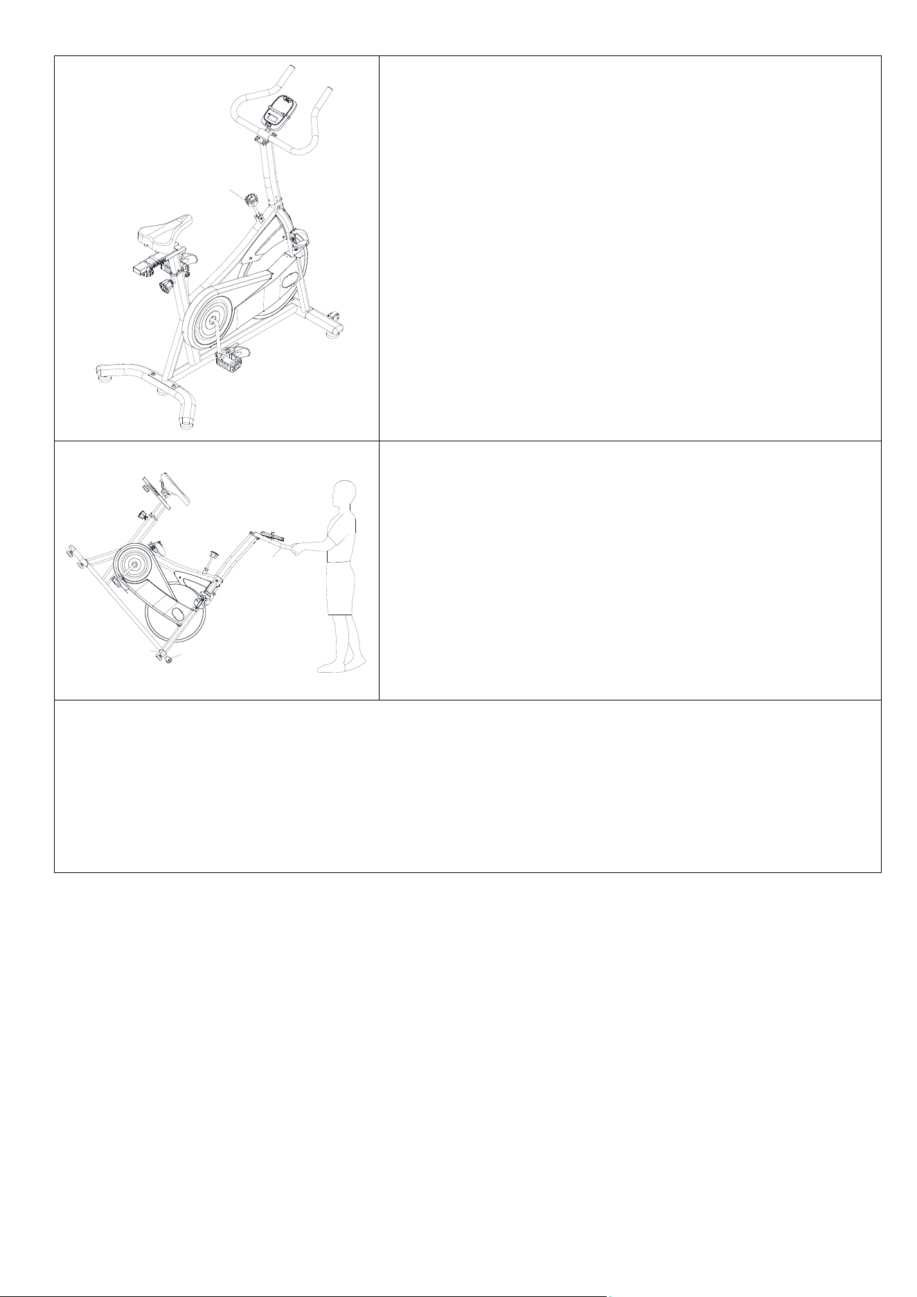
ADJUSTING THE RESISTANCE
Adjust the resistance of the bike using the Tension
Control Knob (No. 43). Increase the level of resistance
by turning the Tension Control Knob (No. 43) to the
RIGHT (clockwise), decrease the level of resistance by
turning the Tension Control Knob (No. 43) to the LEFT
(counter-clockwise).
EMERGENCY BRAKE
During use, users can stop the bike completely by
pushing down on the Tension Control Knob (No. 43).
Pushing down on the Tension Control Knob (No. 43)
will enforce the brake and bring the bike to an immediate
stop.
TRANSPORTING THE BIKE
Stand at the front of the bike so that you’re directly in
front of the handlebar. Firmly grasp and hold each side of
the Handlebar (No. 5), place one foot on the Front
Stabilizer (No. 3) and tilt the bike towards you until the
transportation wheels on the Front Stabilizer (No. 3)
touch the ground. With the Transportation Wheels (No.
73) on the ground, you can transport the bike to the
desired location with ease.
9
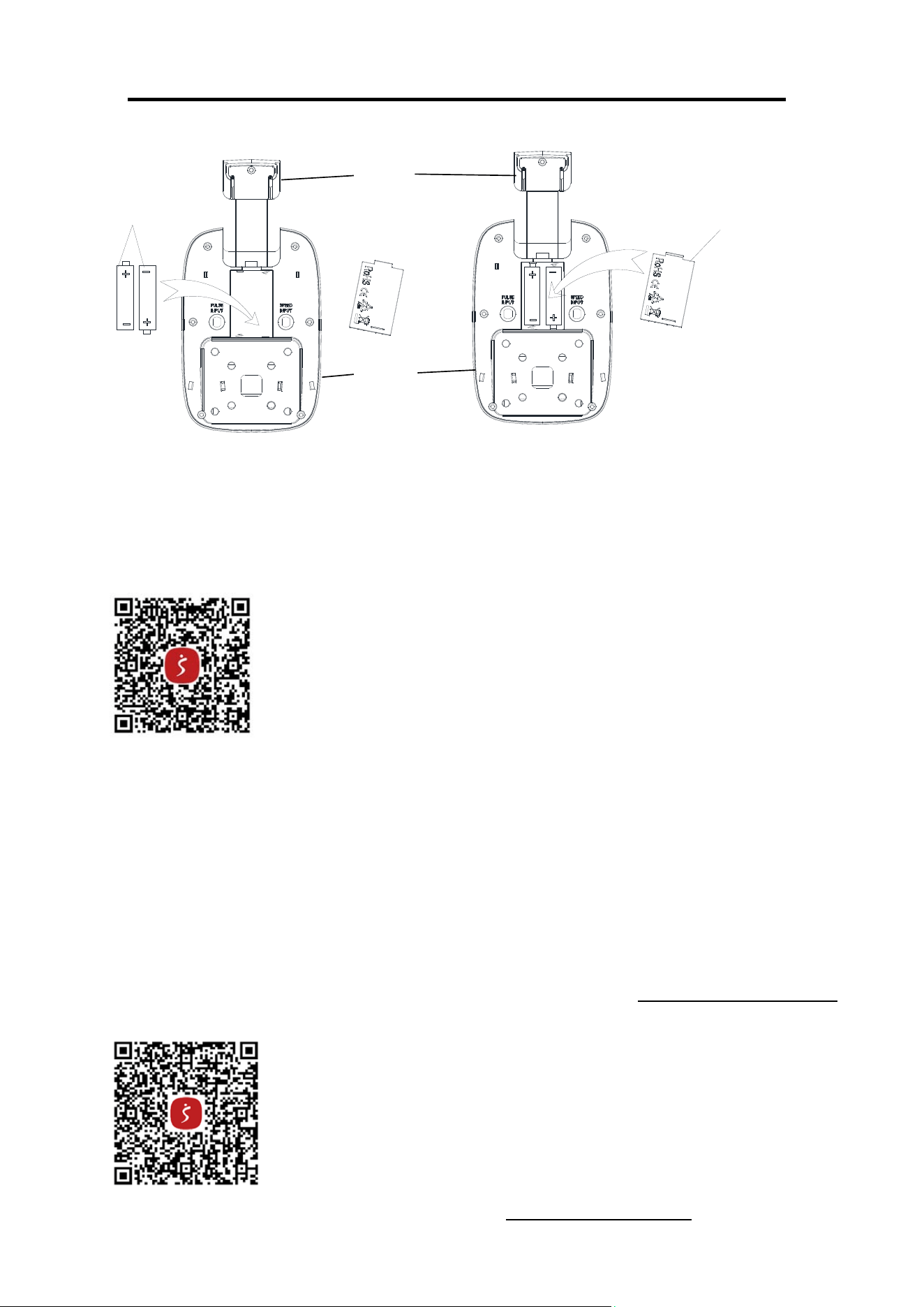
BATTERY INSTALLATION & REPLACEMENT
Battery
Battery Cover
Dispose the old battery (1.5V, AAA) according to your regional guidelines.
APP CONNECTION:
Connect Smart Equipment to SunnyFit App:
1. Scan to download SunnyFit from the app store:
2. Ensure that the Bluetooth function is turned on from your mobile device.
3. If this is your first time using the SunnyFit app, follow the in-app instructions to register for
your free SunnyFit account and log in.
4. Begin any workout activity that matches your smart equipment, then follow the onscreen
prompts to search for and connect to your smart equipment.
5. When connected, your stats and records will be displayed at the end of your course/session,
and recorded in your account profile!
Troubleshooting:
If you are having trouble connecting your smart equipment, visit www.sunnyfit.com/guide or
scan the QR code below:
If you require additional support, please contact support@sunnyfit.com
A
62
10
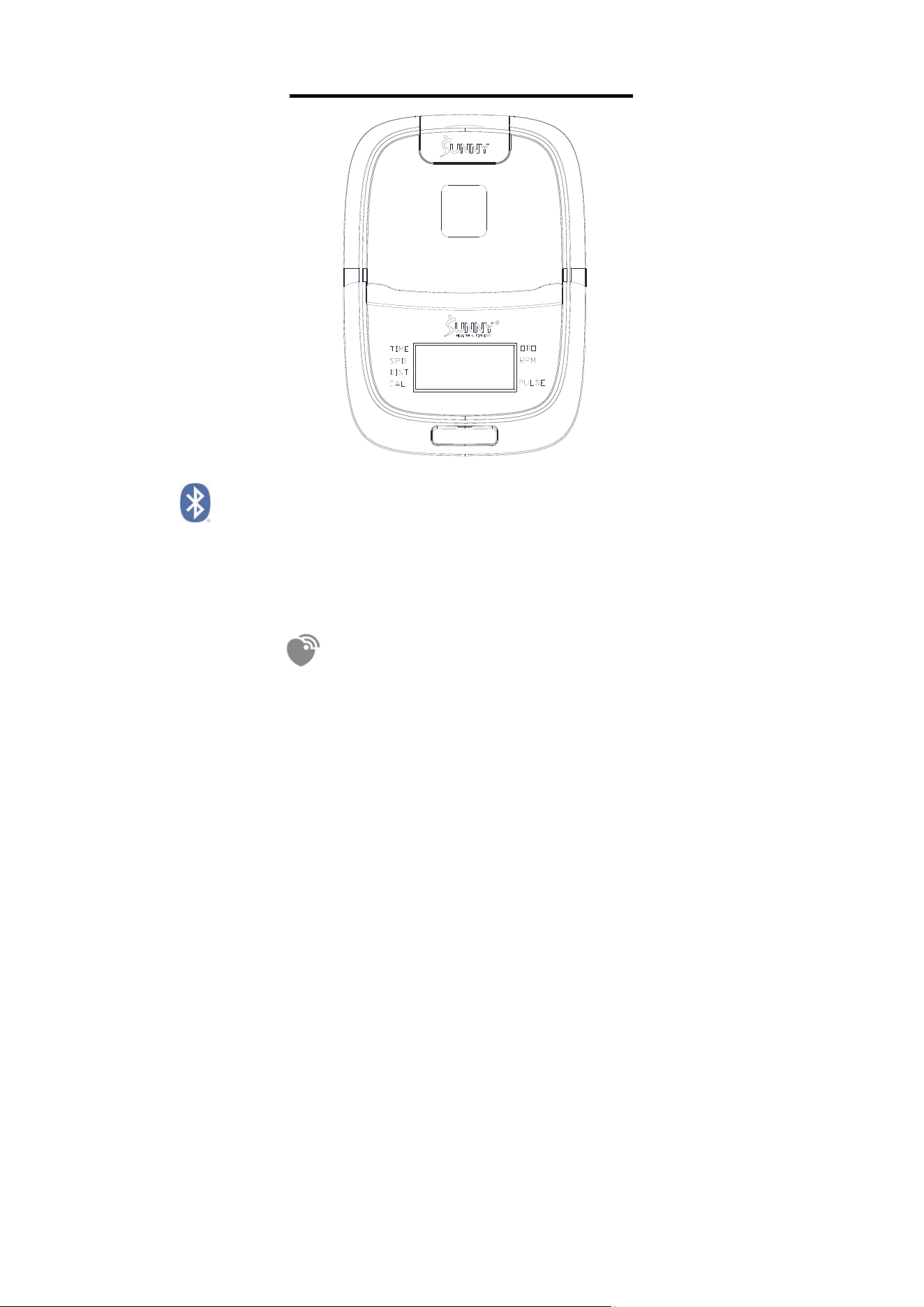
EXERCISE COMPUTER
BLUETOOTH :
1. The Bluetooth icon will flash when the computer is on or wakes from sleep mode. If no Bluetooth
connection is established within 3 minutes, the Bluetooth icon will turn off.
2. The Bluetooth icon will stay on when it is connected.
WIRELESS HEART RATE
1. The wireless heart rate icon will flash when the computer is on. If the heart rate monitor is not
connected within 1 minute, the wireless heart rate icon will turn off.
2. After exercise resumes, the wireless heart rate icon will flash. If the heart rate monitor is not
connected within 1 minute, the wireless heart rate icon will turn off.
3. When the computer wakes from sleep mode, the wireless heart rate icon will flash. If the heart
rate monitor is not connected within 1 minute, the wireless heart rate icon will turn off.
4. The wireless heart rate icon will flash when the MODE key is pressed. If the heart rate monitor is
not connected within 1 minute, the wireless heart rate icon will turn off.
5. The wireless heart rate icon will stay on when the heart rate monitor is connected.
NOTE: The heart rate monitor is not included. Wireless heart rate function works with SunnyFit
Heart Rate Monitor HR200. HR200 can only connect to the computer when the wireless heart rate
icon is flashing.
FUNCTION BUTTON
MODE
Press the button to switch display or automatically display through each function value in sequence
every 6 seconds.
Hold the MODE key for 2 seconds to reset all values except ODO when Bluetooth is not connected.
Press and hold the MODE key for 6 seconds to disconnect from both the SunnyFit APP and the
heart rate monitor; then, the computer will enter sleep mode.

11
OPERATION
1.POWER ON
Installs 2 pieces of 1.5V AAA batteries. (Whenever batteries are removed, all the functions values
will be reset to zero.)
2.1 WAKE UP
After entering speed signal, each function will skip to display. STOP will be displayed once no
speed signal detected for 10 seconds.
2.2 SLEEP MODE
The computer will shut off automatically and disconnect the heart rate monitor if there is no activity
for 4 minutes when Bluetooth is not connected.
3.SCAN
After power on or press the mode button, automatically scan through each function value in
sequence every 6 seconds. SCAN-->TIME-->SPD-- > DIST-- >CAL-->ODO--> RPM-->PULSE-->
SCAN
4.TIME
Accumulates total training time from 00:00 up to 999:59.
5.SPD
Display current training speed from 0.00 up to 9999.9 M/H
6.CAL
Accumulates calories consumption during training from 0.0 up to 9999.9 kcal
Note: This data is a rough guide for comparison of different exercise sessions which can not be
used in medical treatment.
7.ODO
Track the total distance traveled since battery installation from 0.00 up to 9999.9 Mile.
8.DIST
Displays the current movement distance of the user, with the display range of 0.00 to 9999.9 Mile.
9. RPM
Revolution(s) Per Minute
10. PULSE (Needs to pair with the Bluetooth device)
Display the user's heart rate from 30-240 upon pulse signal detected with pulse symbol flashing.
The pulse graphic will not flashing upon no pulse signal detected. and when there is no heart rate,
“P” is displayed.
NOTE:
1. If the computer displays abnormally, please re-install the battery and try again.
2. Battery Spec: 1.5V or AAA (2PCS).
3. The batteries must be removed from the appliance before it is scrapped and that they are
disposed of safely.
12
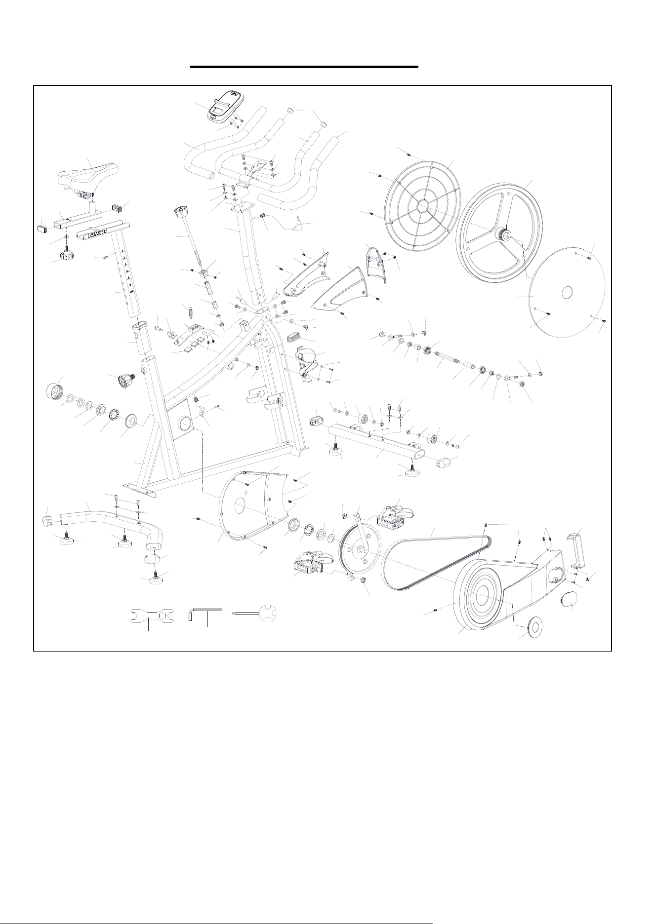
EXPLODED DIAGRAM
46
43
44
45
44
4
58
60
62
63
60
5
61
58
59
9
30
64
59
9
47
48
49
52
9
31
14
53
9
57
56
58
66
27
15
27
65
67
68
14
27
27
14
72
9
39
15
15
28
27
24
22
26
25
23
18
21
20
19
17
15
64
9
57
69
50
54
55
51
38
2
37
36
26
25
32
33
34
35
1
8
9
11
7
10
10
11
10
15
29
27
30
70
71
14
11
72
73
8
9
31
9
73
11
10
10
3
15
16
15
13
12
15
40
41
6
41
42
85
85
86
87
85
85
85
86
85
74
75
77
78
79
81
82
83
78
77
75
76
31
76
31
80
84
9
88
90
91
92
31
27
9
89
89
89
89
89

13
PARTS LIST
No. Description Spec. Qty.
No. Description Spec. Qty.
1 Main Frame 1 47 S
q
uare Nut M10 1
2 Seat Post 1 48 Tension Sprin
g
Φ1.5*Φ12 1
3 Front Stabilize
r
149Screw M8*35 1
4 Handlebar Post 1 50
Magnetic Plate
Connection Seat
1
5 Handleba
r
151Ma
g
net Plate 1
6 Seat Slide
r
152Ma
g
net 25*20*5 3
7 Rear Stabilize
r
1 53 Cowhide Brake 35*30*8 1
8 Screw M8*20 4 54 Hex Nut M8*H3.8 1
9 Washe
r
Φ16*1.5 15 55 Hex Nut M8*H16 1
10 Foot Pad M8*25 5 56 Sensor Wire L=720 1
11 End Ca
p
60*3*1.5 4 57 Screw M8*10 2
12 Crank Seal Rin
g
1 58 Screw M8*16 6
13 Decorative Cove
r
1 59Sprin
g
Washe
r
D8 4
14 Screw M5*12 8 60 Foam Gri
p
Φ25*450 2
15 Screw ST4.2*16 10 61 Screw M5*10 4
16 Front Cove
r
137.9*19.1*32 1 62 Compute
r
1
17 Belt 6PJ480 1 63 Circular End Ca
p
Φ25*1.5 2
18 Left Lockin
g
Nut 1/2--20 1 64 Connectin
g
line L=550 1
19 Ri
g
ht Pedal 1/2- R 1 65 Ma
g
net Plate Cove
r
-L 1
20 Belt Pulle
y
Φ220*20 1 66 Curved Gasket Φ16*1.5 2
21 Ri
g
ht Lockin
g
Nut 1/2- 20 1 67 Ma
g
net Plate Cove
r
-R 1
22
Washer Φ40*T2.8
1
68 Decorative Cove
r
145*117*52 1
23 Left Pedal 1/2- L 1 69 Plu
g
60*30*1.5 1
24
Sleeve - Right 15/16" 1
70 Bottle Holde
r
1
25
Ball Bearing Φ44.5(12) 2
71 Washe
r
Φ10*1.2 2
26
Bearing Bush Φ56.6*T16 2
72 Screw M8*40 2
27
Screw ST4.2*16 7
73 Trans
p
ortation Wheel Ф42*Ф8*20 2
28 Inner Chain Cove
r
407.6*274*10 1 74 Hex Nut M12*1.0*H19.5 1
29 Sensor Base 20*15*9 1 75 Pull Rod Φ12.5*M8 2
30 Wire Clam
p
Plu
g
Φ15.5*Φ12*Φ3 2 76 Hex Nut M8*H6.8 2
31 Nut M8*H7.5 5 77 Cone-axle Sleeve Φ22*Φ12.2 2
32
Locking Nut - Left 7/8"L(24) 1
78 Hex Nut M8*H6.8 2
33
Washer Φ35*T2 1
79 S
p
acer Sleeve Φ18*Φ12.1 1
34
Hex Nut 7/8"L(24) 2
80 Bearin
g
6201 1
35 Axis Sleeve Φ61*Φ32.5*33 1 81 Fl
y
wheel Axle Φ12*158 1
36 Ad
j
ustment Knob M16*1.5 1 82 Bearin
g
Limit Sleeve Φ16*12.1 1
37 Frame Line
r
60*30*1.5 1 83 Bearin
g
6001 1
38 Screw M5*10 1 84 Hex Nut M12*1.0*10 1
39 Ad
j
ustment Knob M8*20 1 85 Screw ST4.2*19 6
40 Washe
r
Φ20*2.0 1 86 Wheel Shield Φ364*16 2
41 S
q
uare End Ca
p
40*20*2.0 2 87 Fl
y
wheel 8KG 1
42 Seat 185*260*103 1 88 Outer Chain Cove
r
642*280*65 1
43
Tension Control
Knob
Φ10*220 1 89 Hex Nut M8*H6 5
44 Screw M5*6 2 90 O
p
en End Wrench S13-S17-S19 1
45 Brake Cove
r
1 91 Allen Wrench S6 1
46 Brake Inner Sleeve 16*16*54 1 92 S
p
anne
r
S13-S14-S15 1
Version:1.0

14