

Installation Guide
Model: ZL700
Lock Body: America Standard Mortise with 5 Latches
Version: 1.0
English

A new lock is defined as always in open mode until it is locked once by a IC card.
Please register an authorized card, a time sync card, and a room card initially for the
new lock.
The lock is equipped with keys for manual unlocking. Remove the keys from the
package and keep them in a safe place.
To power on the lock, four alkaline AA batteries (not included) are required. Non-
alkaline and rechargeable batteries ARE NOT RECOMMENDED.
Do not remove the batteries when the lock is in working state.
When the battery power is low, the lock will beep to remind the user to replace the
batteries. Make sure not to mix up the polarities while replacing the batteries.
Avoid contact with corrosive substances. Do not hang any object on the handle.
The built-in software manages the operation of access cards. Please refer the
software user manual.
1.
2.
3.
4.
5.
6.
7.
8.
For further queries, please contact the seller.
Important Notes

Table of Contents
Packing List.....................................................................................................................1
Installation Diagram.......................................................................................................2
Installation Procedure....................................................................................................2
1. Check Opening Direction.......................................................................................................................2
2. Drill Holes on the Door.............................................................................................................................3
3. Remove the Guide Plate..........................................................................................................................3
4. Installing Mortise.......................................................................................................................................4
5. Installing Outdoor Unit............................................................................................................................5
6. Installing Indoor Unit...............................................................................................................................6
7. Installing Strike Plate and Box...............................................................................................................7
8. Test the Lock by Mechanical Key.........................................................................................................8

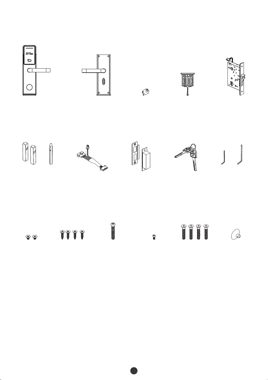
Packing List
1
A
B
A
B
Screw EScrew B Screw C Screw D
Mortise
Cylinder
Battery Box
Indoor UnitOutdoor Unit
Strike Plate
and Box
Spindle Hex Wrench
Keys
Vacuum
Sucker
Screw A
Transfer Cable
Note: This type of lock is suitable for a door thickness of 36 mm to 55 mm. If the door is
thicker than 55 mm, this lock will not be suitable. Please contact the sales person for
queries.

2
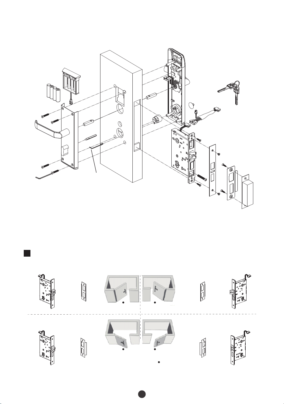
Installation Diagram
Installation Procedure
1
Check Opening Direction
Screw E
Hex Wrench B
Indoor Unit
Screw E
Battery
(not include)
Battery Box
Sp
in
d
le A
Sp
i
n
d
l
e B
Hex Wrench A
S
c
re
w D
Spi
n
d
le A
Cy
l
in
d
er
Mortise
S
c
re
w C
Screw B
Screw A
Screw B
Screw A
Screw B
Keys
Transfer Cable
Vacuum
Sucker
Outdoor UnitDoor
Strike Plate
and Box
Person Location
Left Inward
Right Inward
Left Outward
Right Outward
Mortise Strike Plate Strike Plate Mortise
Mortise Strike Plate Strike Plate Mortise
Note: Please install the Mortise and Strike Plate according to the above illustration.
3
2
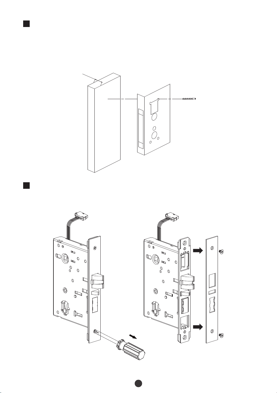
Drill Holes on the Door
Paste the Installation Template at the desired handle height.
Mark for the holes to be drilled and drill the marked places.
1)
2)
3
Remove the Guide Plate
Unscrew the Screw A and remove the Guide Plate.
36 to 55 mm
Installation Template
Screw B
4
4
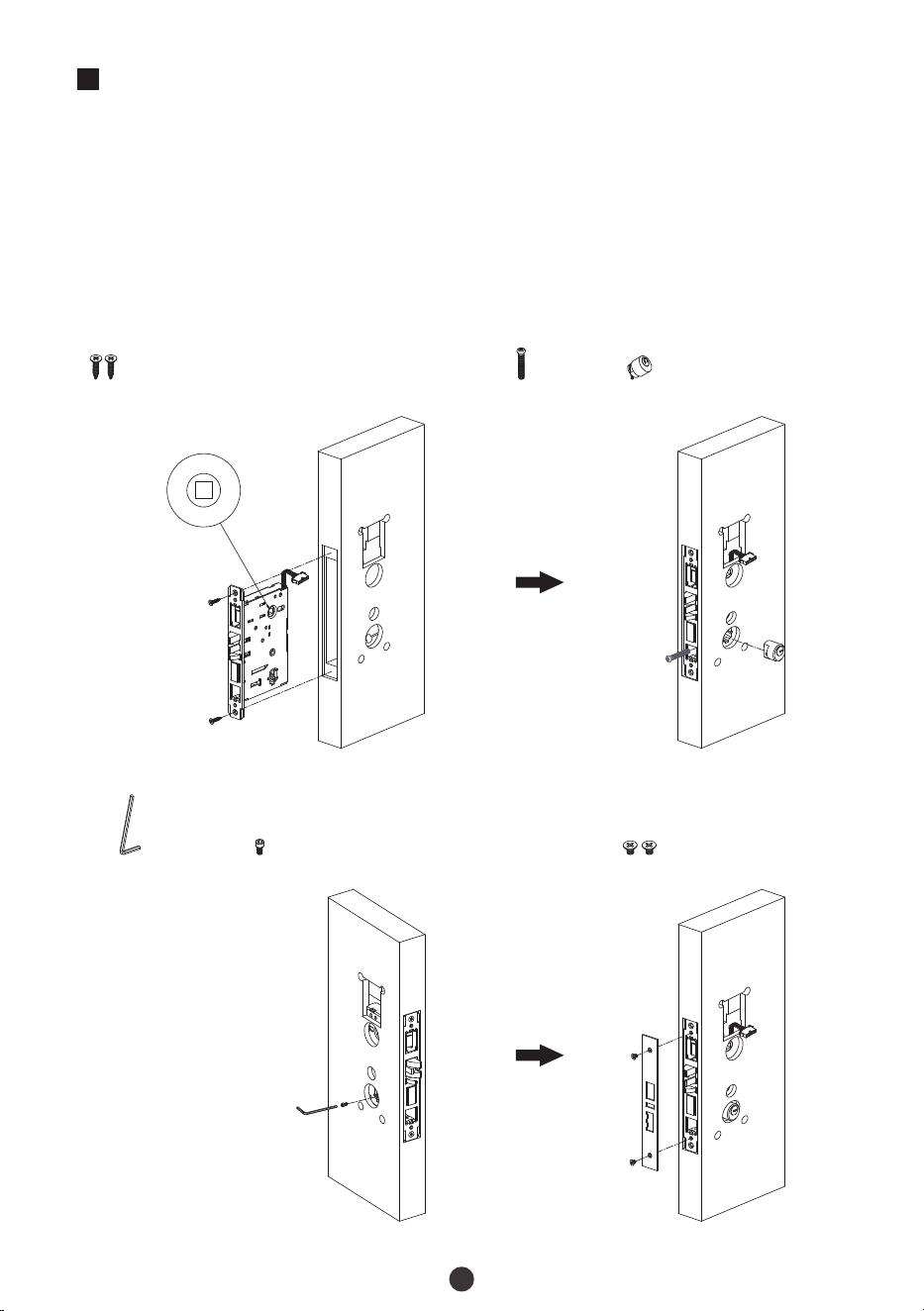
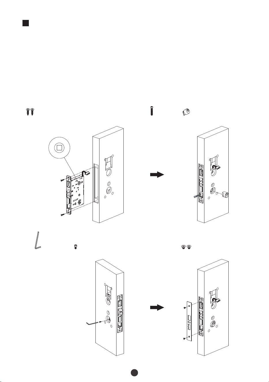
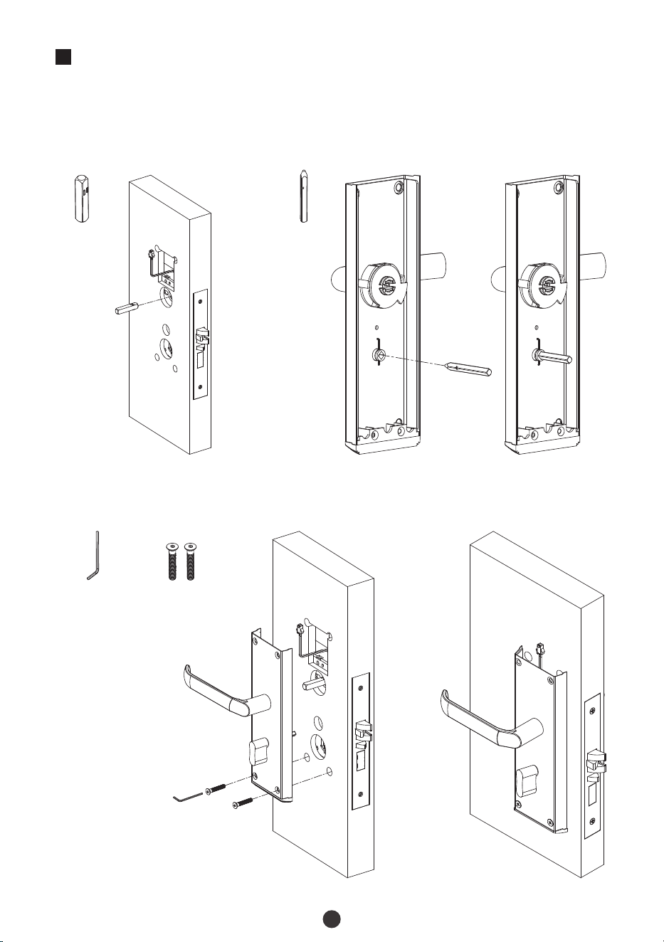
Installing Mortise
Make sure the side of Mortise without circle points is toward outdoor, then insert the
Mortise into the drilled hole, secure it with Screw B.
Make sure the Cylinder toward Outdoor Unit, secure Cylinder with Screw C and Screw
D by Hex Wrench A.
Secure the guide plate with Screw A, make sure the cable toward Outdoor Unit.
1)
2)
3)
Note: Screw C has been secured in the Mortise before delivery.
Hex Wrench A
Screw D Screw A
Screw C
Cylinder
5
5
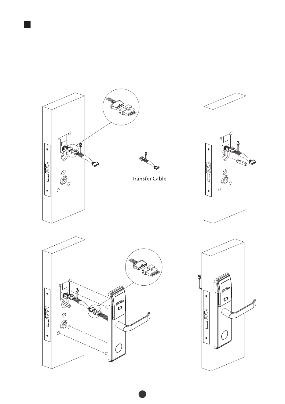
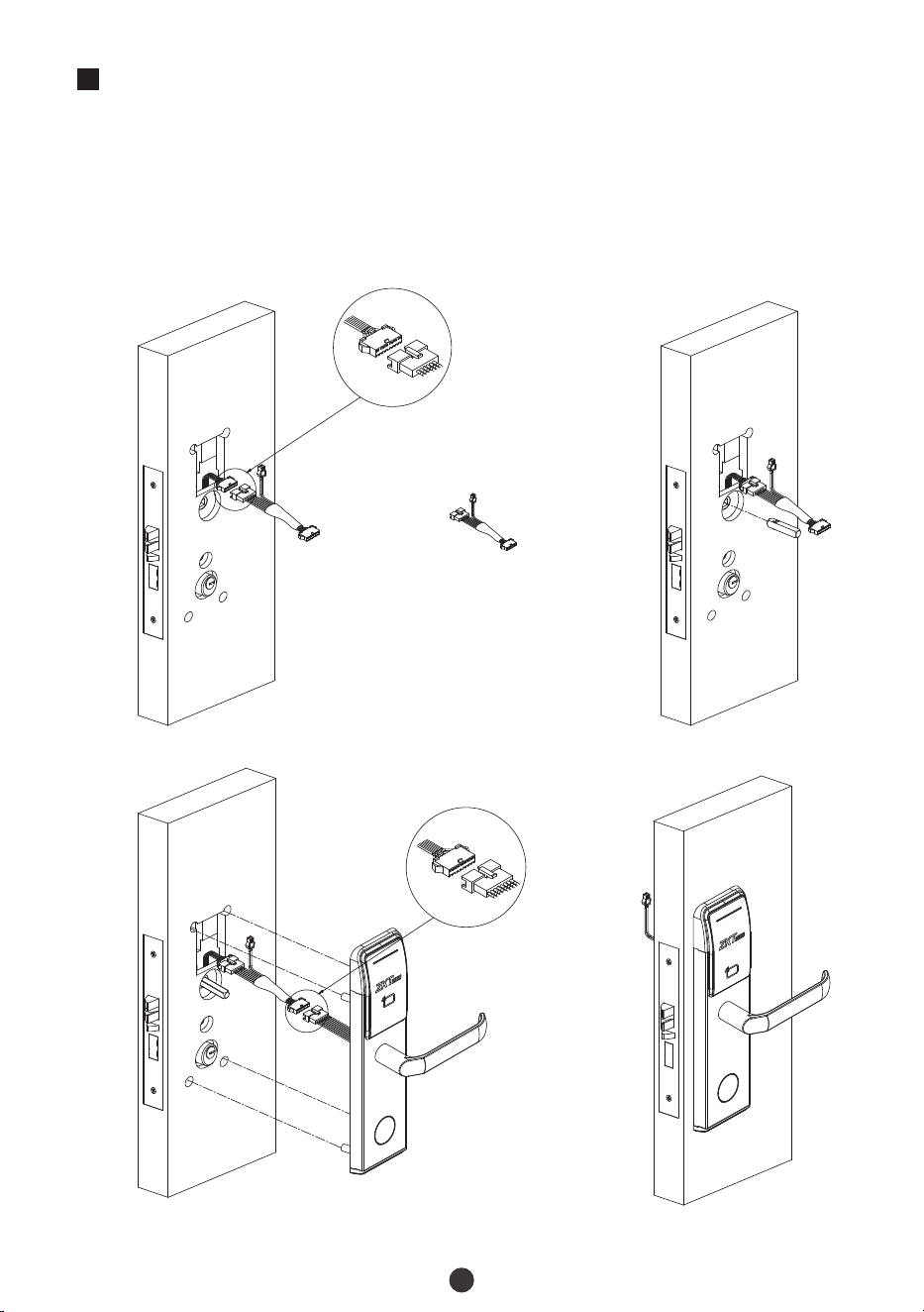
Installing Outdoor Unit
Connect 6 PIN end of Transfer Cable with Mortise cable.
Insert a Spindle A into the clutch toward Outdoor Unit.
Attach the Outdoor Unit to the door by connecting 8 PIN end of Transfer Cable with
mainboard on the drilled holes.
1)
2)
3)

6
6
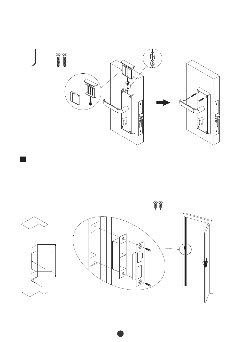
Installing Indoor Unit
Insert another Spindle A into clutch toward Indoor Unit, and insert the Spindle B into
turn knob.
Secure the below of Indoor Unit with 2 Screw E.
1)
2)
Spindle A Spindle B
Screw EHex Wrench B

7
Connect the cable of Battery Box with Transfer Cable, put in 4 Alkaline AA batteries,
and insert the Battery Box into Indoor Unit.
Secure the Battery Box and Indoor Unit with 2 Screw E.
3)
4)
Screw EHex Wrench B
7
Installing Strike Plate and Box
Make sure that the Strike Box is aligned with the latch bolt. Then, use the Installation
Template to drill holes.
Align the Strike Plate and Box with the drilled holes and secure them with Screw B.
1)
2)
Screw B
131mm
89.5mm*29.5mm
4mm
2
7
mm

8
8
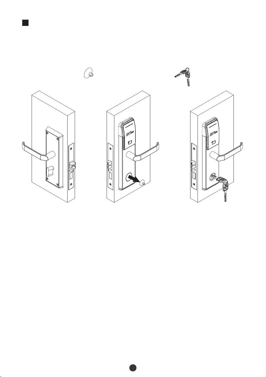
Test the Lock by Mechanical Key
Remove the cover on the key hole with the Vacuum Sucker.
Insert the key into the Cylinder and rotate it by 90°, then rotate down the handle to
open the door, it means normal.
1)
2)
Keys
Vacuum
Sucker
Cerradura Hotelera de Estándar Americano de 5 Pestillos
Versión: 1.0
Modelo: ZL700
Guía de Instalación
Español

La cerradura por estándar se encuentra en modo siempre abierto hasta que se
bloquee una vez con una tarjeta IC.
Registre una tarjeta autorizada, una tarjeta de sincronización de hora y una tarjeta de
habitación inicialmente para la nueva cerradura.
La cerradura está equipada con llaves para desbloqueo manual. Saque las llaves del
paquete y guárdelas en un lugar seguro.
Para encender la cerradura, se requieren cuatro pilas alcalinas AA (no incluidas). NO
SE RECOMIENDAN pilas recargables y no alcalinas.
No quite las baterías cuando la cerradura esté en funcionamiento.
Cuando la carga de la batería es baja, la cerradura emitirá un pitido para recordarle al
usuario que debe reemplazar las baterías. Asegúrese de no mezclar las polaridades al
reemplazar las baterías.
Evite el contacto con sustancias corrosivas. No cuelgue ningún objeto de la manija.
El software integrado gestiona el funcionamiento de las tarjetas de acceso. Consulte
el manual del usuario del software.
1.
2.
3.
4.
5.
6.
7.
8.
Para más consultas, póngase en contacto con el vendedor.
Precauciones

Tabla de Contenido
Contenido.......................................................................................................................1
Diagrama de Instalación................................................................................................2
Proceso de Instalación...................................................................................................2
1. Dirección de Apertura..............................................................................................................................2
2. Realice los Agujeros en la Puerta..........................................................................................................3
3. Remueva la Placa Guía.............................................................................................................................3
4. Instalación del Mortaja............................................................................................................................4
5. Instalación de la Unidad Interior...........................................................................................................5
6. Instalación de la Unidad Interior...........................................................................................................6
7. Instalación de la Placa de Contrachapa..............................................................................................7
8. Pruebe la Cerradura con la Llave Mecanica.......................................................................................8
1
Nota: Esta cerradura es apta para un grosor de puerta de 36 mm a 55 mm. Si la puerta es
ms gruesa de 55mm, esta cerradura no es apta para su proyecto. Por favor contacte a
suagende de ventas.
Contenido
A
B
A
B
Unidad Exterior Unidad Interior Cilindro Caja de Baterías
Mortaja
Perno
Cable de transferencia
Placa de Caja
Contrachapa
Llave Mecánica Llave
Hexágonal
Tornillo A Tornillo B Tornillo C
Tornillo D
Tornillo E
Ventosa
de Succin
1
Nota: Por favor instale el mortaja y la placa de contrachapa de acuerdo a esta ilustracin.
Diagrama de Instalación
Unidad Exterior
Ci
li
nd
ro
Caja de Baterías
Mortaja
Tornillo A
Tornillo B
Tornillo B
Tornillo A
Placa de Caja
Contrachapa
Tornillo B
Cable de transferencia
Llave Mecánica
Llave Hexágonal A
T
o
rni
l
lo D
Pe
rn
o B
Pern
o A
Llave Hexágonal B
Tornillo E
Unidad Interior
Ventosa
de Succin
P
er
no A
Tornillo E
La puerta
Baterías
(no incluidas)
Proceso de Instalación
Dirección de Apertura
Mortaja
Placa de
Contrachapa
Placa de
Contrachapa
Mortaja
Mortaja
Placa de
Contrachapa
Placa de
Contrachapa
Mortaja
Posición del Usuario
Interior Izquierda
Interior Derecha
Exterior Izquierda
Exterior Derecha
T
o
rn
i
ll
o C
2

2
Coloque la plantilla de instalación a la altura deseada de la manija.
Marque los agujeros a perforar y perfore los lugares marcados.
1)
2)
3
Remueva la Placa Guía
Desatornille el tornillo D y retire la placa guía.
36 to 55 mm
Realice los Agujeros en la Puerta
Plantilla de Instalación
3
4
4
Instalación del Mortaja
Asegúrese de que el lado de la mortaja sin los puntos circulares esté hacia el exterior,
luego inserte la mortaja en el orificio perforado y fíjela con el tornillo B.
Asegúrese de que el cilindro esté orientado hacia la unidad exterior, asegure el
cilindro con el tornillo C y el tornillo D con la llave hexágonal A.
Asegure la placa guía con el Tornillo A, asegúrese de que el cable apunta hacia la
Unidad Exterior.
1)
2)
3)
Nota: El tornillo C se ha asegurado en la mortaja antes de la entrega.
Tornillo C
Tornillo B Cilindro
Llave
Hexagonal A
Tornillo D
Tornillo A
5
5
Instalación de la Unidad Interior
Conecte el extremo de 6 pines del cable de transferencia con el cable de Mortaja.
Inserte un eje A en el embrague hacia la unidad exterior.
Fije la unidad exterior a la puerta conectando el extremo de 8 pines del cable de
transferencia con la placa principal en los orificios perforados.
1)
2)
3)
Cable de transferencia
6
6
Inserte otro eje A en el embrague hacia la unidad interior e inserte el eje B en el pomo
giratorio.
Asegure la parte inferior de la unidad interior con 2 tornillos E.
1)
2)
Instalación de la Unidad Interior
Perno A
Tornillo E
Llave
Hexagonal B
Perno B
7
Conecte el cable de la caja de baterías con el cable de transferencia, coloque 4
baterías alcalinas AA e inserte la caja de baterías en la unidad interior.
Asegure la caja de baterías y la unidad interior con 2 tornillos E.
3)
4)
7
Instalación de la Placa de Contrachapa
Asegrese de que la placa est alineada con el pestillo. Luego, use la plantilla de
instalación para perforarlos agujeros.
Alinee la placa y la caja con los orificios perforados y asegúrelos con el tornillo A.
1)
2)
131mm
89.5mm*29.5mm
4mm
2
7
mm
Llave
Hexagonal B
Tornillo E
Tornillo B
8
8
Pruebe la Cerradura con la Llave Mecanica
Retire la tapa del orificio de la cerradura con la ventosa de succin.
Inserte la llave en el orificio y grela 90, luego gire la manija hacia abajo para abrir la
puerta, lo que significa normal
1)
2)
Ventosa
de Succin
Llave Mecánica

This device complies with Part 15 of the FCC Rules. Operation is subject to the following
two conditions: (1) This device may not cause harmful interference, and (2) This device
must accept any interference received, including interference that may cause undesired
operation.
This equipment has been tested and found to comply with the limits for a Class B digital
device, pursuant to Part 15 of the FCC Rules. These limits are designed to provide
reasonable protection against harmful interference in a residential installation. This
equipment generates, uses, and can radiate radio frequency energy and, if not installed
and used in accordance with the instructions, may cause harmful interference to radio
communications. However, there is no guarantee that interference will not occur in a
particular installation. If this equipment does cause harmful interference to radio or
television reception, which can be determined by turning the equipment off and on, the
user is encouraged to try to correct the interference by one or more of the following
measures:
IMPORTANT! Any changes or modifications not expressly approved by the party
responsible for compliance could void the user's authority to operate the equipment.
Reorient or relocate the receiving antenna.
Increase the separation between the equipment and receiver.
Consult the dealer or an experienced radio/TV technician for help.
Warning:
FCC RF Radiation Exposure Statement:
This Transmitter must not be co-located or operating in conjunction with any other
antenna or transmitter.
This equipment complies with RF radiation exposure limits set forth for an
uncontrolled environment.
Connect the equipment into an outlet on a circuit different from that to which the
receiver is connected.

ZKTeco Industrial Park, No. 32, Industrial Road,
Tangxia Town, Dongguan, China.
Phone : +86 769 - 82109991
Fax : +86 755 - 89602394
www.zkteco.com
Copyright © 2022 ZKTECO CO., LTD. All Rights Reserved.


