Installation Guide
Version: 1.0
Date: Jan. 2019
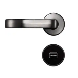
LH7500
1
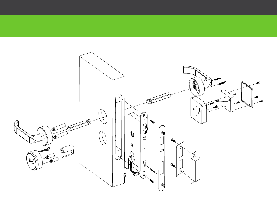
Lock Diagram
Before Installation
A
B
D
G
C
H
O
M
E
I
J
N
F
P
K
L
R
Q
E
I
2
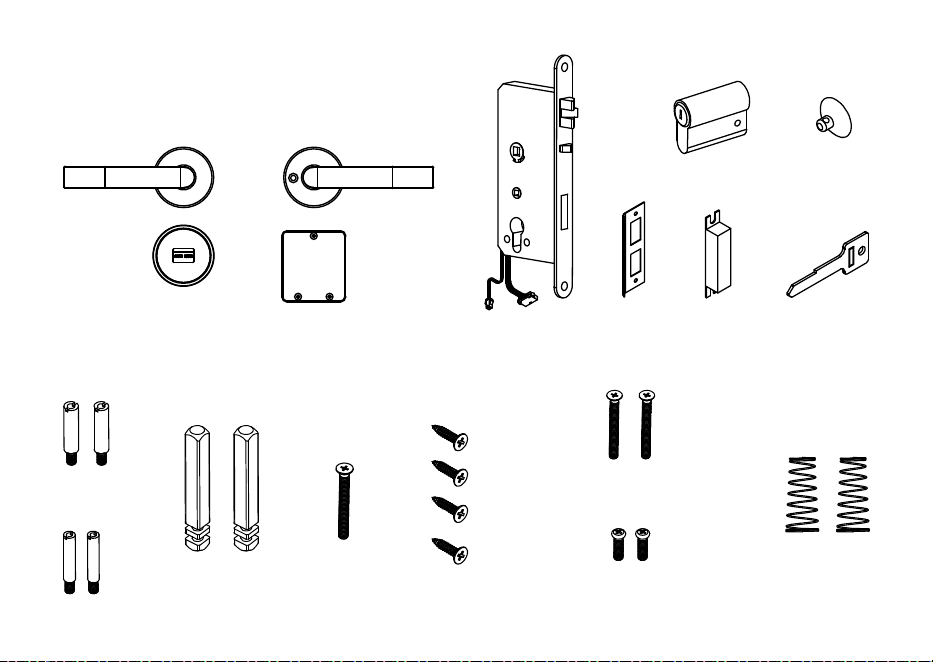
IntheBox
A
N
G
LK
S
C
O
P
E
I
U
B
M
H
F T
D
KM5*40
PM4*20
3
Beforeyou begin
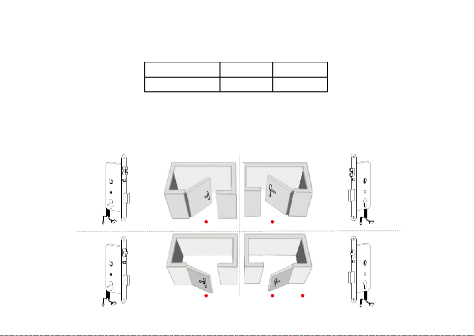
1. Preparing door
Note: Please install the mortise (G) according to the above pictures.
G G
G G
Left hand, open inward Right hand, open inward
2. Determining Handing
Door Thickness O Screws P Screws
38 - 48 mm 40 mm 20 mm
Note: If the door is thicker than 38-48 mm, this lock will not be available.
Standpoint
Left hand, open outward Right hand, open outward
The hand of a door is determined from the secure side of the door. The term "secure" means the side from
which you unlock and enter.

4
Cautions
1. New lock is defined as always open mode until it was unlocked once by mifare card.
2. Please swipe authorised card, time sync card, room card at first for the new lock.
3. The lock is equipped with mechanical keys for manual unlocking. Remove the
mechanical keys from the package and keep them in a safe place.
4. To power on the lock, four alkaline AA batteries (not included) are required.
Non-alkaline and rechargeable batteries ARE NOT RECOMMENDED.
5. Do not remove batteries when the lock is in working state.
6. When battery power is low, the lock will beep to remind user to renew the batteries.
Please do not mix up positive and negative while replacing battery.
7. Avoid contacting with corrosive substances, and do not hang objects on the handle.
8. The software within the lock manages the RFID cards, for more details refer to the
software user manual.
9. If there are any questions, please do not hesitate to contact the seller.
5
Installation
de
si
r
e
d hand
l
e
h
ei
ght
center line of
the handle
door
thick
ness
38~48 mm
backset
54 mm
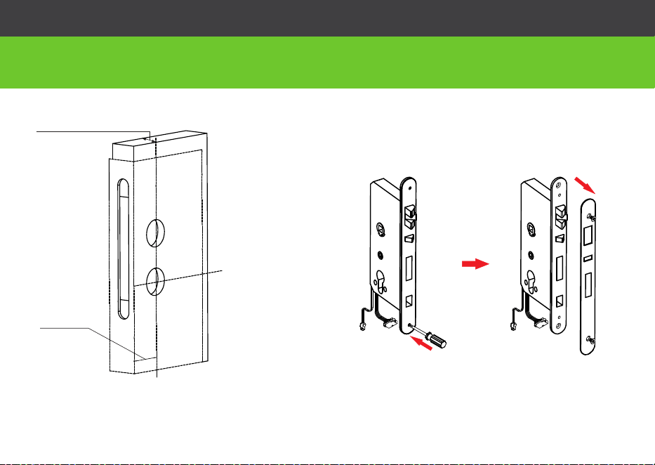
2. Remove the mortise latch plate
1. Drill holes on the door
Note 1: Align the template along the vertical
center line of the mortise (G) at the desired
handle height, and tape it to door.
Note 2: Mark the holes first, then start drilling.
G
J
6
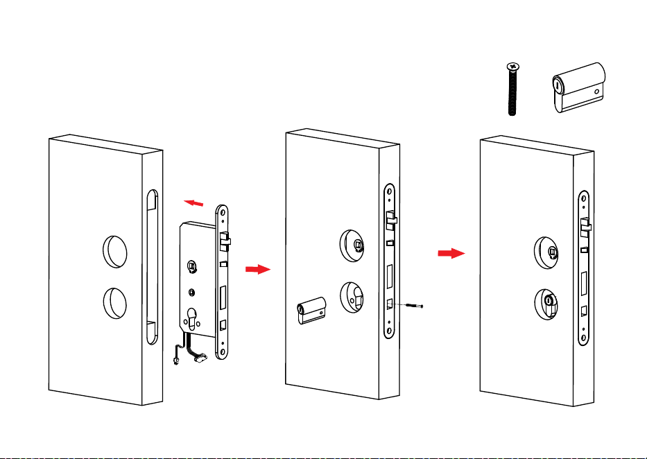
3. Install mortise(G) and cylinder(F)
F
F
H
H
G
H
7
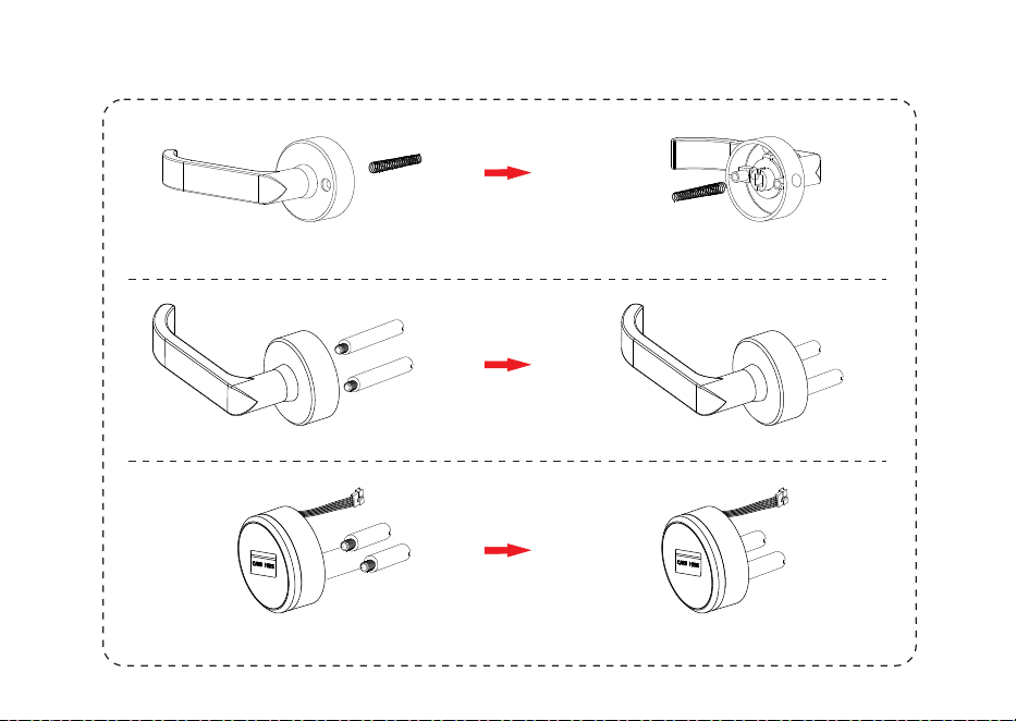
4. Install the coil spring and screw th stud e
B
B
D
A
A
C
U
U
A
M
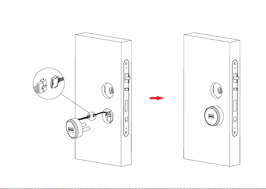
8
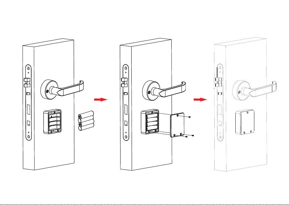
5. Install exterior panel (A)
A
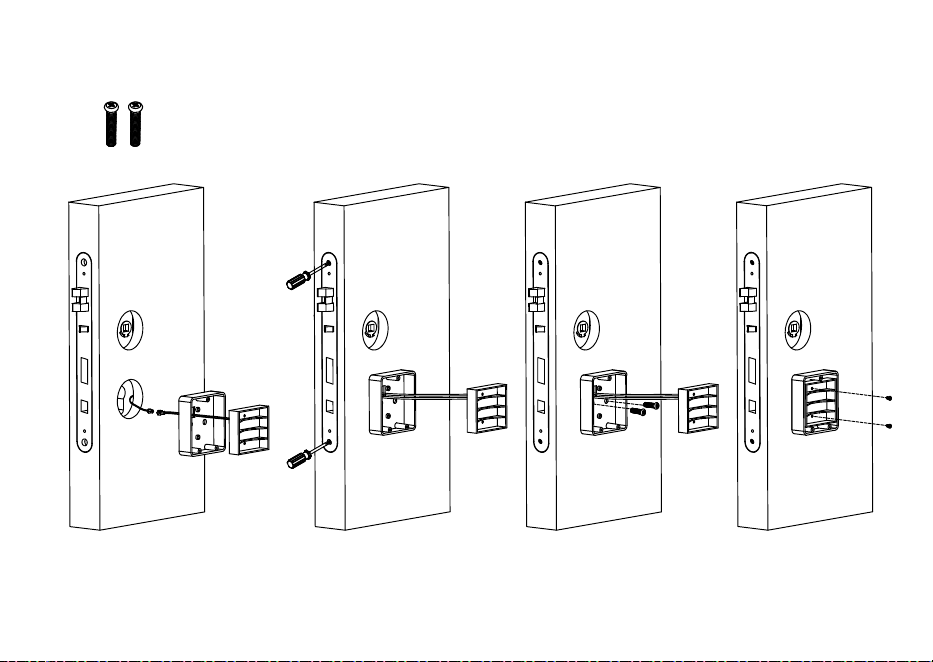
9
6. Install in Nterior panel ( )
N
Q
P
P
10
7. Fix wi h th t e mortise(G)
J
B B
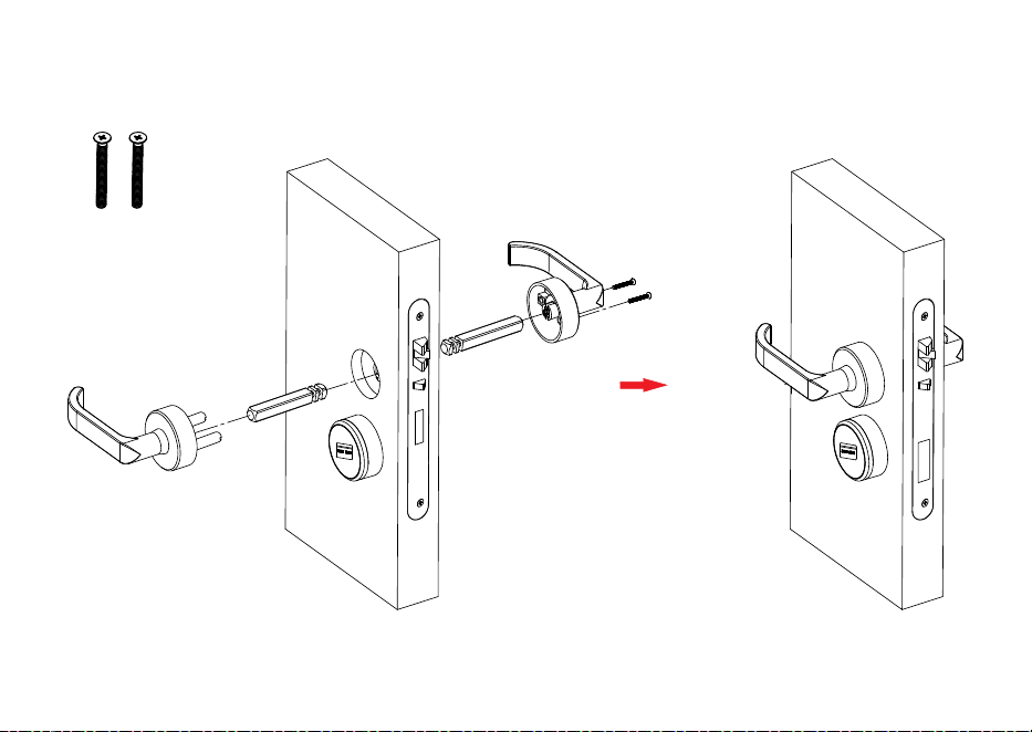
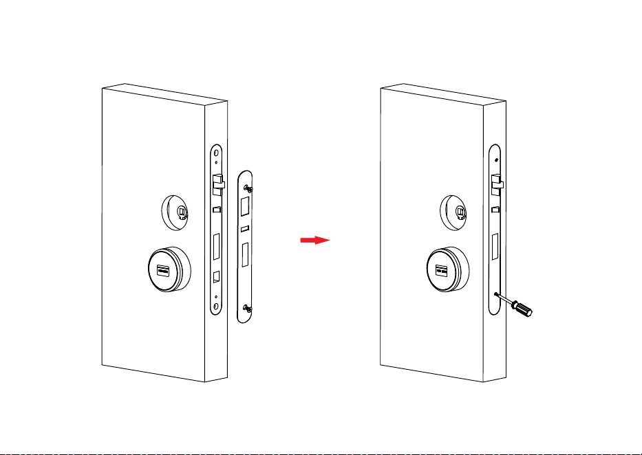
11
8. Mount handles
A
E
E
O
M
O
12
9. Install the battery
R
13
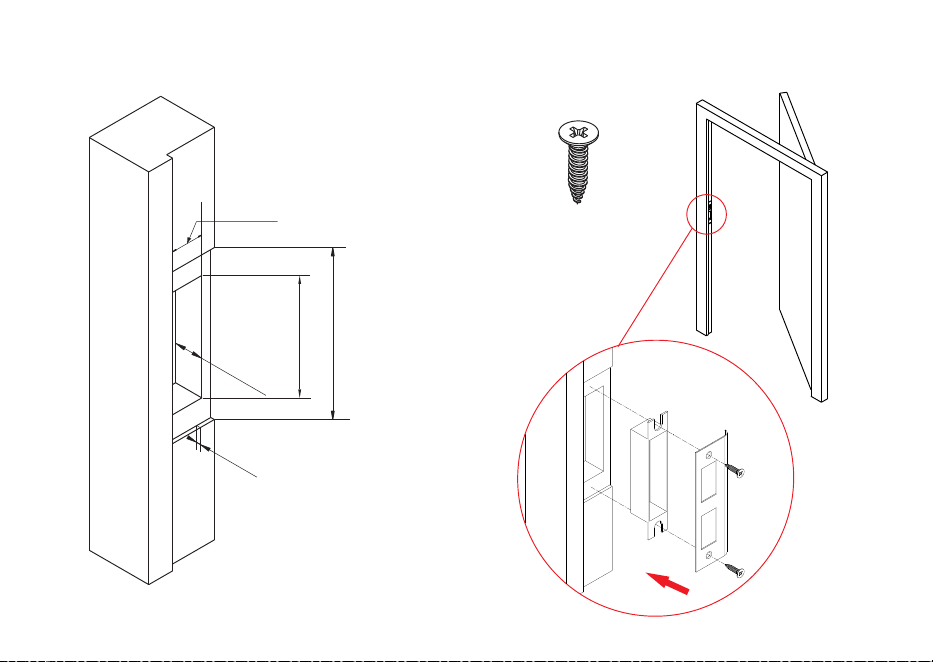
10. Mark and drill holes for strike
3
.5 mm
21 mm
181 mm
124 mm
21 mm
I
K
L
I
14
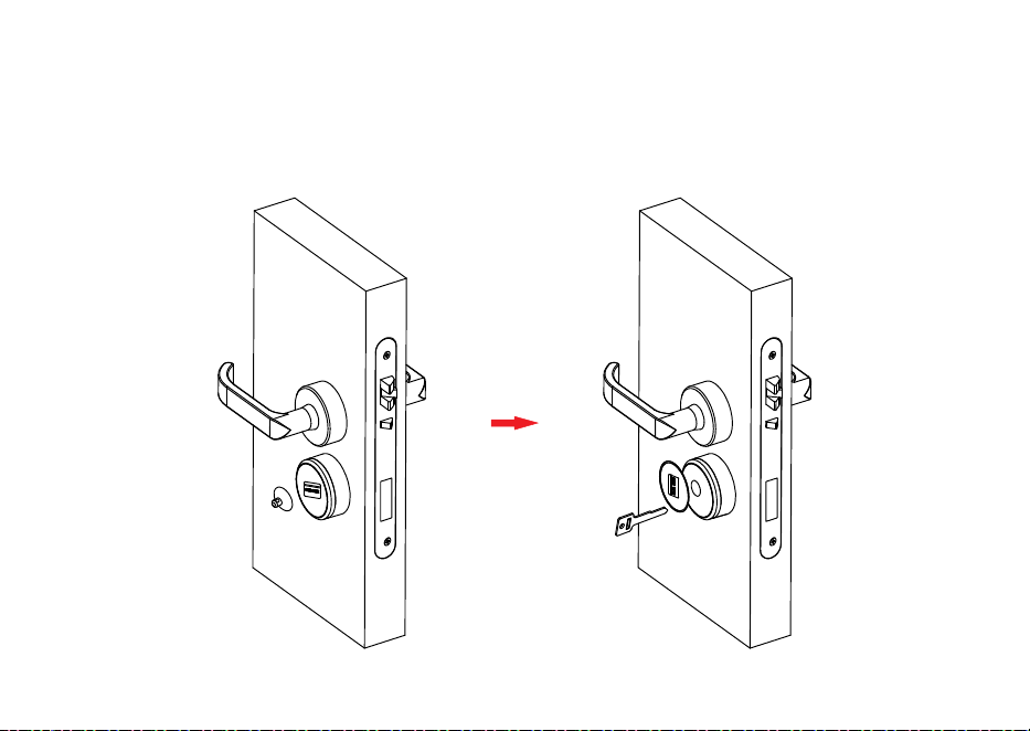
Step1: Remove the cover on the key hole with a sucker(T ).
Step2: Insert mechanical key (S) into the key hole and rotate it at 90°.
11. Test Lock by mechanical key (S)
T
S

15
ZK Building, Wuhe Road, Gangtou, Bantian, Buji Town,
Longgang District, Shenzhen China 518129
Tel: +86 755-89602345
Fax: +86 755-89602394
www.zkteco.com
© Copyright 2017. ZKTeco Inc. ZK Teco Logo is a registered trademark of ZK Teco or a related company. All other product and company names mentioned are used
for identification purposes only and may be the trademarks of their respective owners. All specifications are subject to change without notice. All rights reser ved.


