
Installation Guide
Model: SL02-ZL140H/SL02-LH190H
Due to regular upgrades of systems and products, ZKTeco could not guarantee exact consistency between
the actual product and the written information in this manual.
Version: 1.1
English

Cautions
Table of Contents
1.
2.
3.
4.
5.
6.
7.
What’s in the Box...................................................................................................................1
Installation Diagram.............................................................................................................2
Installation Procedure..........................................................................................................3
1. Door Properties............................................................................................................................................................................................3
2. Drill Holes on the Door............................................................................................................................................................................4
3. Removal of the Faceplate and Installing Mortise...................................................................................................................5
4. Installation of the Outdoor Unit.......................................................................................................................................................6
5. Installation of the Indoor Unit............................................................................................................................................................7
6. Installation of the Battery and the Cover....................................................................................................................................8
7. Installation of the Strike Plate and Box........................................................................................................................................9
8. Test the Lock and Reset.......................................................................................................................................................................10
For further queries, please contact the seller.
A new lock is dened as always in open mode until it is locked once by Authorization Card or Default
Net Card.
The lock is equipped with keys for manual unlocking. Remove the keys from the package and keep
them in a safe place.
To power on the lock, four alkaline / LR6 AA batteries (not included) are required. Non-alkaline and
rechargeable batteries ARE NOT RECOMMENDED.
Do not remove the batteries when the lock is in working state.
When the battery power is low, the lock will beep to remind the user to replace the batteries. Make
sure not to mix up the polarities while replacing the batteries.
Avoid contact with corrosive substances. Do not hang any object on the handle.
The built-in software manages the operation of access cards. Please refer the software user manual.
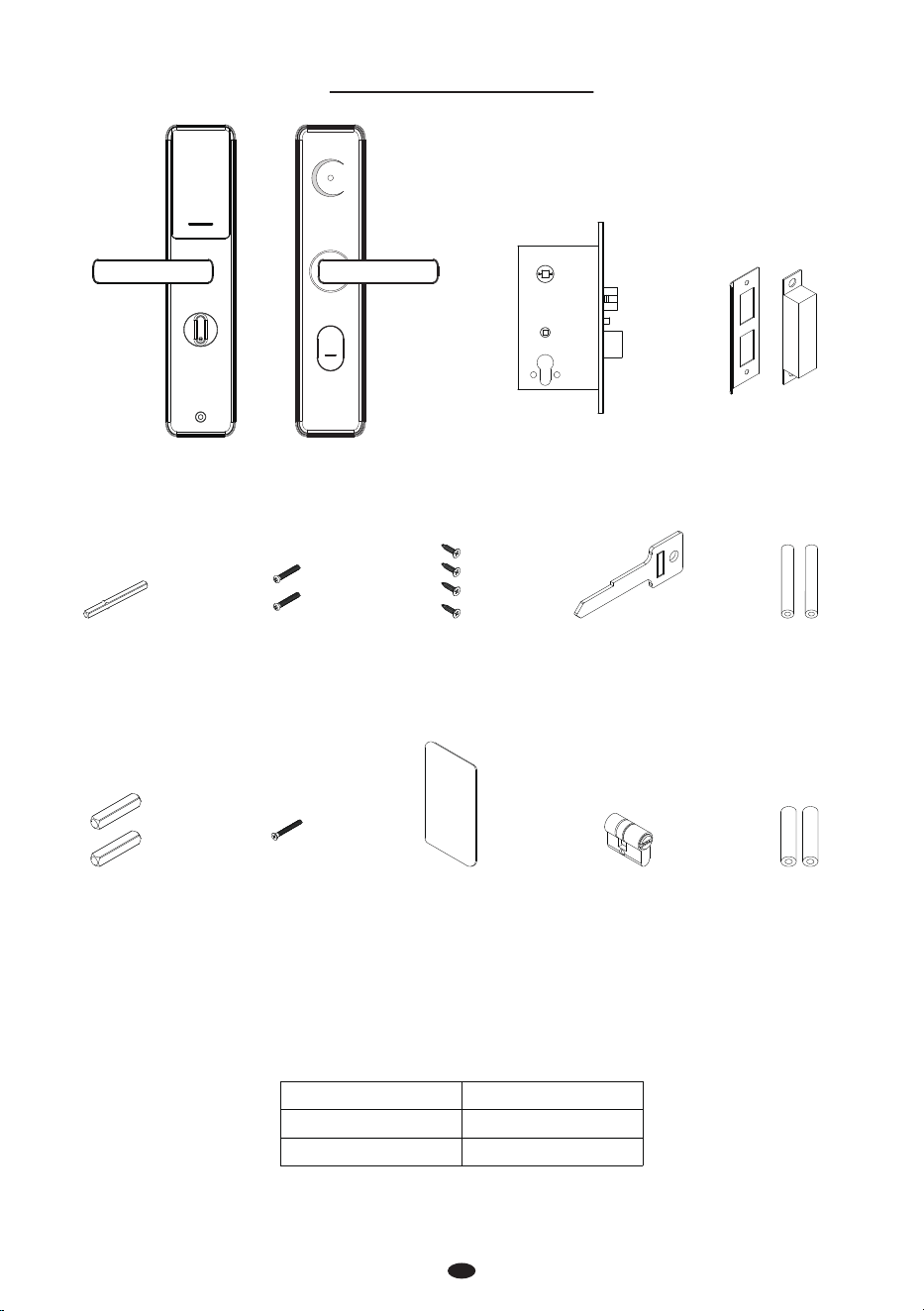
What’s in the Box
1
Note: For doors with a thickness of 40-63mm, using 40mm studs allows the key to fully insert. When
60mm studs are used on doors exceeding 63mm thickness, the key length becomes insucient ,the
key handle needs to be cut to increase the insertion length.
Door Thickness
40 to 63mm
60 to 80mm
Stud
Stud B 5*40mm
Stud A 5*60mm
Indoor Unit Outdoor Unit Strike Plate and BoxMortise
Spindle A
5*5*60mm
Screw A
5*40mm
Screw B
4*20mm
Keys Stud A
5*60mm
Spindle B
8*8*40mm
Screw C
5*50mm
IC card Cylinder Stud B
5*40mm
2
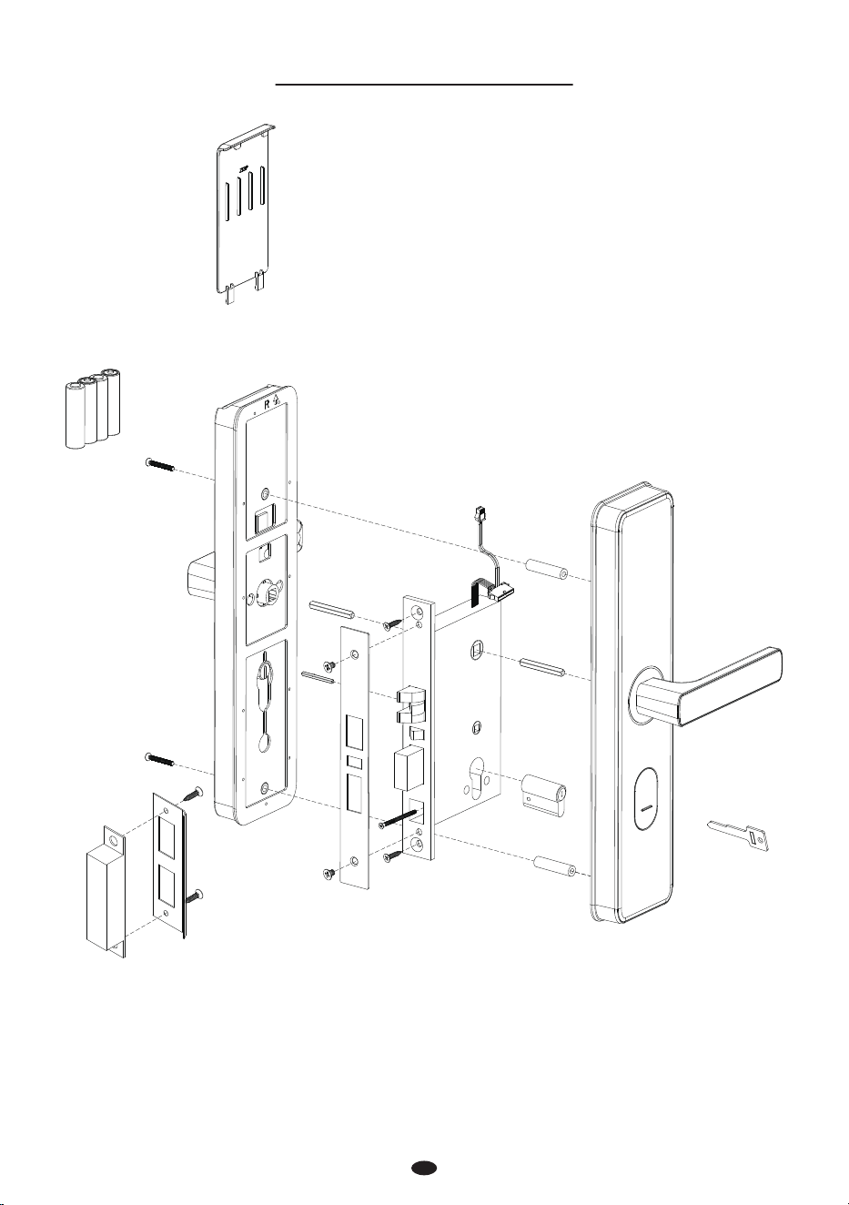
Installation Diagram
Battery Cover
Indoor Unit
Screw A
Screw A
Screw B
Screw C
Screw B
Stud A or B
Key
Screw B
Spindle B
Mortise
Spindle B
Cylinder
Spindle A
Battery
(Not include)
1. Door Properties
A. Measure the Door Thickness
Measure the door thickness and select the proper stud length. For details, please refer to the table
contents on Page 1.
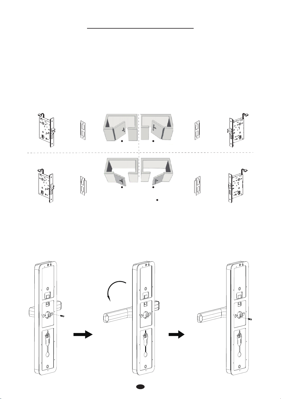
B. Check the Door Opening Direction
The position of the handle is determined by the opening direction of the door. Below is the graphical
representation of the door opening direction in reference to your location outside the room.
Note: Please install the mortise and the strike plate as shown in the illustration above.
C. Adjust the Direction of the Handle (if needed)
1) Remove the screw at the arrow.
2) Rotate the handle in your preferred direction.
3) Tighten the screw again.
Note: It is not possible to adjust the direction of the latch.
3
Installation Procedure
Person Location
Left Inward
Right Inward
Left Outward
Right Outward
Mortise Strike Plate Strike Plate Mortise
Mortise Strike Plate Strike Plate Mortise
180°
4
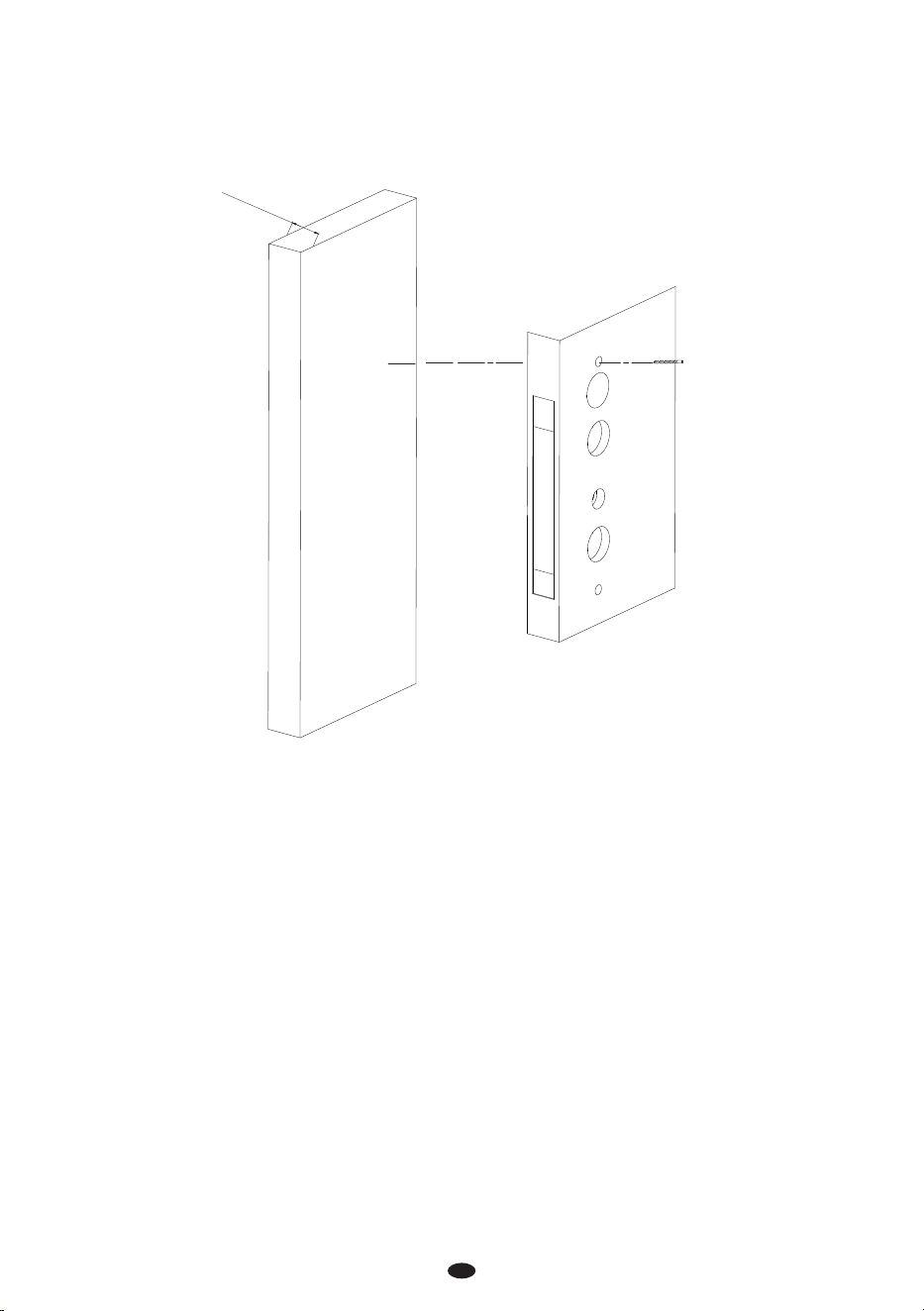
2. Drill Holes on the Door
1) Paste the installation template at the desired handle height.
2) Mark the locations for the drill holes and then drill accordingly.
43 to 63mm
Installation Template
5
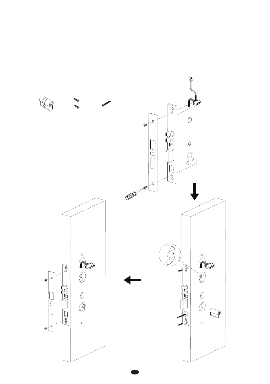
3. Removal of the Faceplate and Installation of the Mortise
Remove the screws from the faceplate of the mortise, and then remove the faceplate.
Make sure that the arrow of the mortise is pointing horizontally.
Insert the Mortise into the drilled hole and then pull the wires of the Mortise out towards the
Outdoor Unit, secure the Mortise with screw B.
Make sure that the cylinder is toward the outdoor unit, and secure the cylinder with screw C.
Secure the Guide Plate.
1)
2)
3)
4)
5)
Cylinder
Screw CScrew B
6
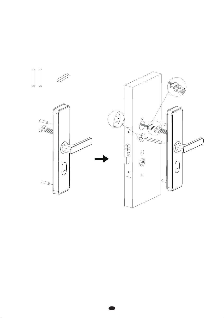
4. Installation of the Outdoor Unit
Insert the studs on the rear of the outdoor unit.
Connect the cables of the mortise to the port on the outdoor unit.
Insert the spindle B into the clutch, and make sure that the arrow of the mortise is pointing horizon-
tally.
Attach the outdoor unit to the door.
Note: Please select either stud A or stud B, use only one set based on the thickness of the door.
1)
2)
3)
4)
Stud A Spindle B
Note: Turn Spindle A 180 degrees to adapt to dierent door thicknesses.
7
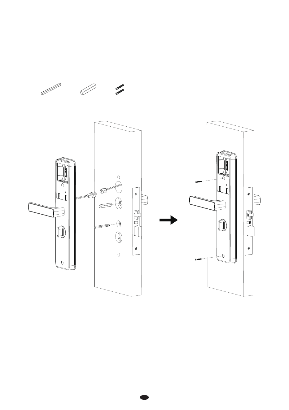
5. Installation of the Indoor Unit
Insert the spindles B and A into the clutches.
Connect the cables of the mortise to the port on the indoor unit.
Attach the Indoor Unit to the door and secure it with screw A.
1)
2)
3)
Spindle A Screw A
Spindle B
8
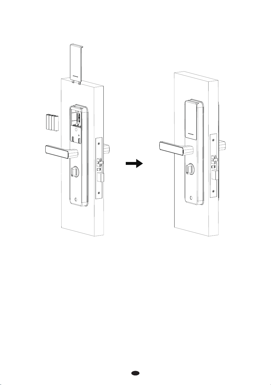
6. Installation of the Batteries and the Cover
Insert four Alkaline AA batteries and cover them with the battery cover.
9
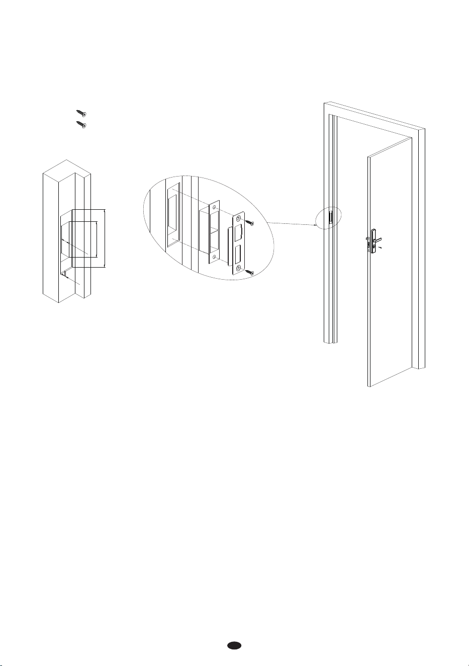
7. Installation of the Strike Plate and Box
Make sure that the strike plate and box is aligned with the latch bolt. Then, use the installation
template to drill holes.
Align the strike plate and box with the drilled holes and secure them with screw B.
1)
2)
3mm
25mm
88mm*24mm
141mm
Screw B
10
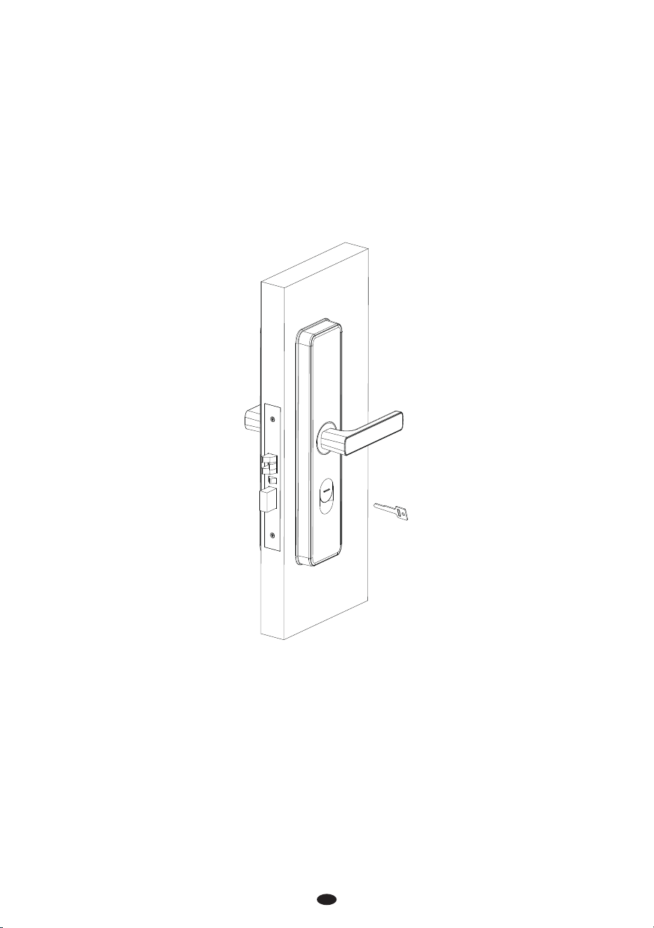
8. Test the Lock and Reset
Press the keyhole cover and softly push upwards.
Put the key into the cylinder and turn it 90°, then lower the handle to open the door, indicating it’s
in the normal position.
Rotate the manual lock button on the indoor unit, and the latch will automatically pop out.
If the lock is bound to other software, the Default Net Card swipe is invalid, or any other issues occur,
please RESET the lock. Use the key to keep the latch bolt retracted, and then remove a battery. After
waiting for three seconds, reinsert the battery, you will hear three beeps and see three green
ashes, indicating a successful reset. Finally, release the key.
1)
2)
3)
4)

This device complies with Part 15 of the FCC Rules. Operation is subject to the following two
conditions: (1) This device may not cause harmful interference, and (2) this device must accept
any interference received, including interference that may cause undesired operation.
This equipment has been tested and found to comply with the limits for a Class B digital device,
pursuant to Part 15 of the FCC Rules. These limits are designed to provide reasonable protection
against harmful interference in a residential installation. This equipment generates, uses, and can
radiate radio frequency energy and, if not installed and used in accordance with the instructions,
may cause harmful interference to radio communications. However, there is no guarantee that
interference will not occur in a particular installation. If this equipment does cause harmful
interference to radio or television reception, which can be determined by turning the equipment
o and on, the user is encouraged to try to correct the interference by one or more of the
following measures:
Reorient or relocate the receiving antenna.
Increase the separation between the equipment and receiver.
Connect the equipment into an outlet on a circuit dierent from that to which the receiver is
connected.
Consult the dealer or an experienced radio/TV technician for help.
FCC RF Radiation Exposure Statement:
This Transmitter must not be co-located or operating in conjunction with any other antenna
or transmitter.
This equipment complies with RF radiation exposure limits set forth for an uncontrolled
environment.
IMPORTANT! Any changes or modications not expressly approved by the party responsible for
compliance could void the user's authority to operate the equipment.
Warning: