
NanoVNA-F V2
Portable Vector Network Analyzer
User Guide
Rev. 2.0
(For firmware V0.3.0)
SYSJOINT Information Technology Co., Ltd.

Contents
1. Introduction ................................................................................................................................................ - 1 -
1.1. About NanoVNA-F V2 .................................................................................................................... - 1 -
1.2. Features ............................................................................................................................................... - 1 -
1.3. Specifications ..................................................................................................................................... - 2 -
1.4. VNA basics .......................................................................................................................................... - 3 -
2. Appearance ................................................................................................................................................. - 4 -
3. User interface ............................................................................................................................................. - 5 -
3.1. Main screen ........................................................................................................................................ - 5 -
3.2. Menu screen ....................................................................................................................................... - 7 -
3.3. Keyboard screen ............................................................................................................................... - 8 -
4. Menus ........................................................................................................................................................... - 8 -
4.1. DISPLAY ............................................................................................................................................... - 8 -
4.2. MARKER ............................................................................................................................................ - 11 -
4.3. STIMULUS ......................................................................................................................................... - 14 -
4.4. CAL ..................................................................................................................................................... - 15 -
4.5. RECALL/SAVE .................................................................................................................................. - 19 -
4.6. TDR ..................................................................................................................................................... - 20 -
4.7. CONFIG ............................................................................................................................................. - 21 -
4.8. STORAGE .......................................................................................................................................... - 24 -
5. User Defined Information .................................................................................................................... - 24 -
6. PC Software.............................................................................................................................................. - 25 -
7. Console Command ................................................................................................................................ - 28 -
7.1. Command Syntax .......................................................................................................................... - 28 -
7.2. Command Description ................................................................................................................. - 29 -
8. Firmware Upgrade ................................................................................................................................. - 37 -
9. Hardware Architecture ......................................................................................................................... - 38 -

NanoVNA-F V2 portable vector network analyzer user guide V2.0
©2016-2021 SYSJOINT Information Technology Co., Ltd.
- 1 -
1. Introduction
1.1. About NanoVNA-F V2
NanoVNA-F V2 is new generation 3GHz portable vector network analyzer. It is designed with
4.3-inch IPS LCD and aluminum alloy case. It has a built-in 5000mAh large capacity lithium
battery and the standby time is up to 7 hours. It is full touching screen designend and with 3
side buttons at the same time.
The design of NanoVNA-F V2 is based on edy555’s NanoVNA and OwOcomm’s SAA-V2, and
the software and UI is deeply optimized. The operation method of NanoVNA-F V2 is compatible
with NanoVNA-F. The measuring frequency range of NanoVNA-F V2 is extended to 3GHz, the
dynamic range is larger, the measurement result is more accurate and the operation is more
convenient.
1.2. Features
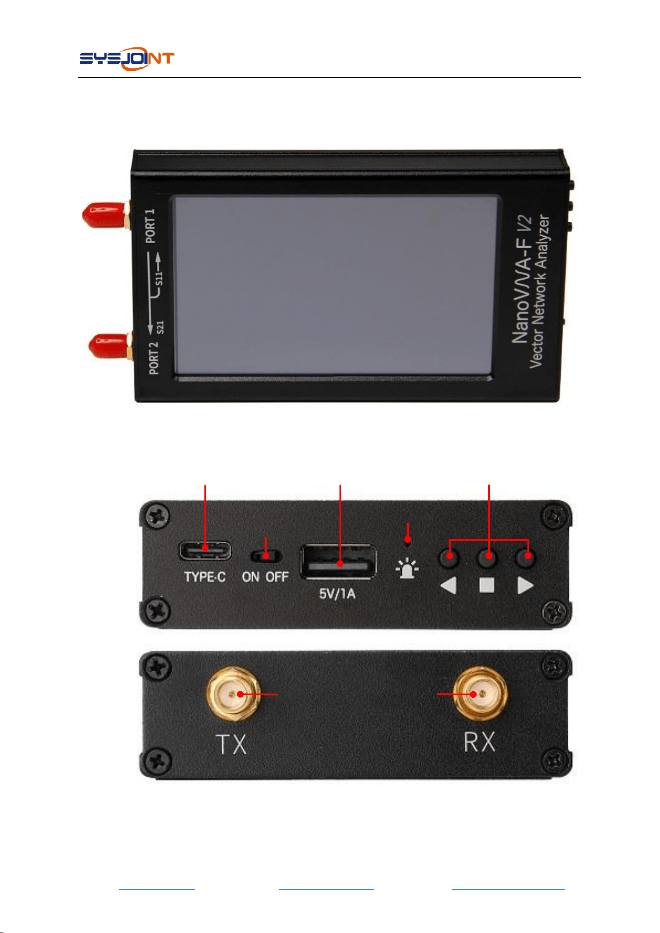
● 4.3-inch IPS LCD, ultra wide viewing angle;
● All aluminum alloy case;
● Dimension: 130mmx75mmx22mm,small and portable;
● SMA RF connectors, easy to connect DUTs;
● Built-in 3.7V 5000mAh lithium battery, standby time up to 7 hours;
● Full touching screen design, with 3 side buttons at the same time;
● Language: English and Chinese;
● Optimized UI design, make measurement convenient and efficiency;
● Screen brightness adjustable;
● Firmware upgrad via virtual U disk with USB Type-C cable;
● Equipped with high quality SMA calibration kit and RG405 cable;
● 5V/1A USB power output port;
● Charging via USB Type-C, maximum charging current reaches 2A;
● Compatible with nanovna-saver PC software;
● Support screenshot command;

NanoVNA-F V2 portable vector network analyzer user guide V2.0
©2016-2021 SYSJOINT Information Technology Co., Ltd.
- 2 -
1.3. Specifications
Parameter
Specification
Conditions
Frequency range
50kHz~3GHz
RF output power
-10dBm
50kHz - 140MHz
-9dBm
140MHz - 1GHz
-12dBm
1GHz - 2GHz
-14dBm
2GHz - 3GHz
Frequency accuracy
<±0.5ppm
S21 dynamic range
70dB
50kHz - 1.5GHz
60dB
1.5GHz - 3GHz
S11 dynamic range
50dB
50kHz - 1.5GHz
40dB
1.5GHz - 3GHz
Sweep points
201
11-201 configurable
Traces
4
Markers
4
Calibration storage
7
Sweep time
1.5s/101 points
Display
4.3-inch IPS LCD
Resolution: 800*480
Touch screen
RTP
Battery
3.7V 5000mAh
Charging/Data port
USB Type-C
Charging voltage
4.7V - 5.5V
Power output
USB-A 5V/1A
RF connector
SMA
Dimensions
130*75*22mm
Shell material
Aluminum alloy
Operation temperature
0℃-45℃
NanoVNA-F V2 portable vector network analyzer user guide V2.0
©2016-2021 SYSJOINT Information Technology Co., Ltd.
- 3 -
1.4. VNA basics
Vector Network Analyzer (VNA) is the most commonly used instrument in the field of RF and
microwave,VNA measures the reflection and transmission behavior of a device under test
(DUT)across a configured frequency range. VNA is usually used to measure antenna impedance,
cable loss, filters, power splitters, couplers, duplexers, amplifiers, etc.
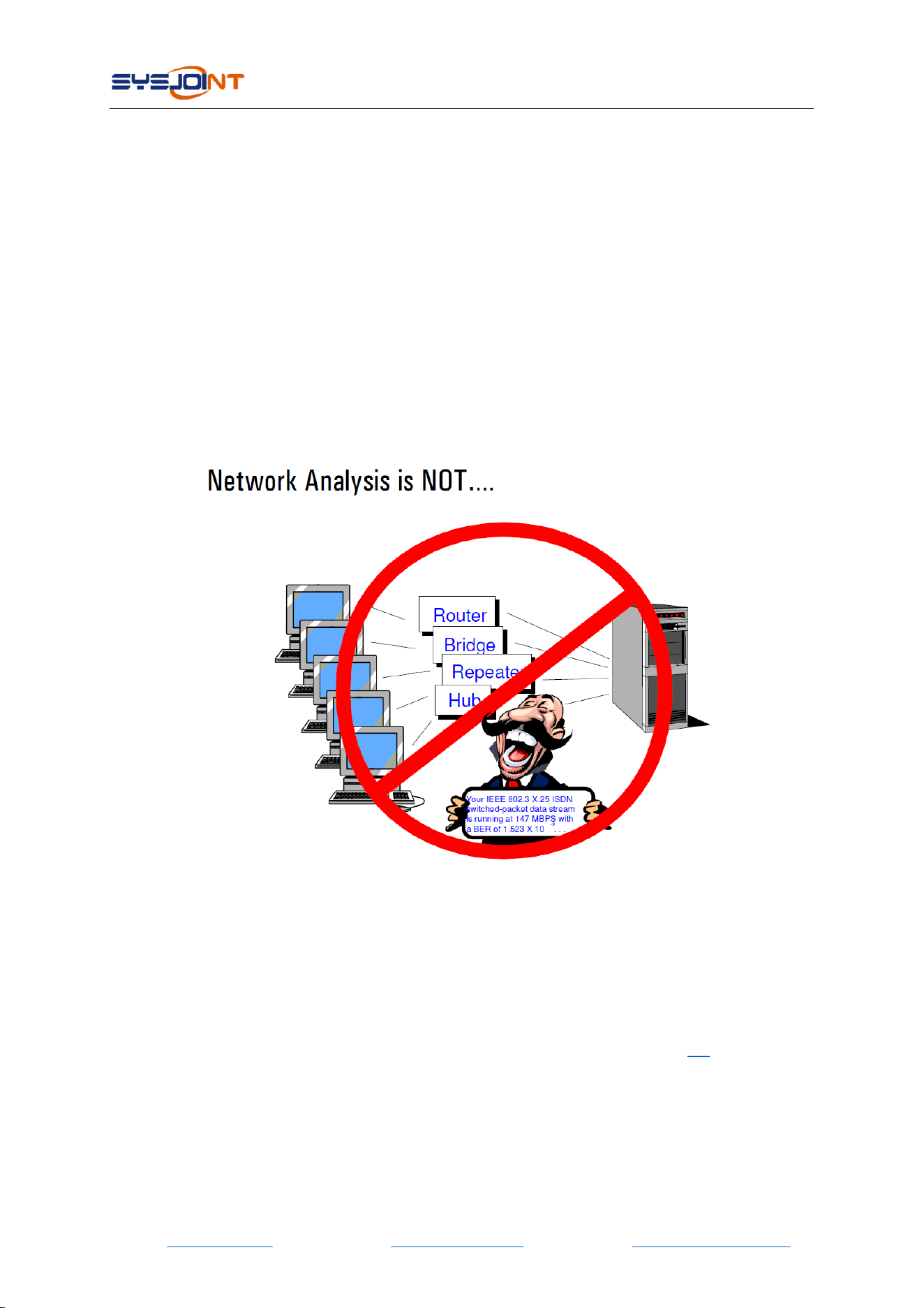
Note that the "network" mentioned here does not refer to a computer networks. When the
name "network analyzer" was coined many years ago, there ware no such things as computer
networks. Back then, networks always referred to electrical networks. Today, when we refer to
the things that network analyzers measure, we speak mostly about devices and components.
NanoVNA-F V2 is a dual-port portable vector network analyzer that can be used to measure
the S11 parameters of a single-port network, or to measure the S11 and S21 parameters of a
dual-port network. If you need to measure the S22 and S12 parameters of the dual-port
network, you can achieve it by exchanging the measurement ports.
VNA must be calibrated before any measurements are performed. See section 4.4 for details。
NanoVNA-F V2 portable vector network analyzer user guide V2.0
©2016-2021 SYSJOINT Information Technology Co., Ltd.
- 5 -
3. User interface
3.1. Main screen
8
5
6
7
9
1 24
3
10
11
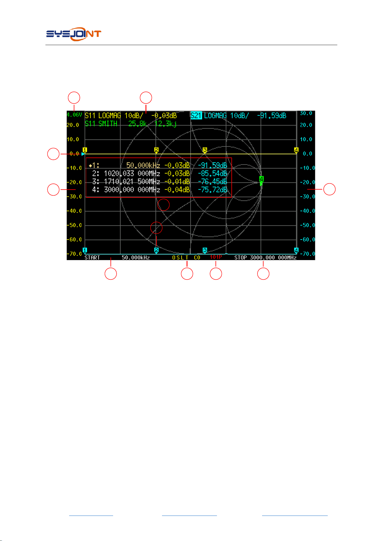
① START frequency
The START frequency is shown in this area.
② STOP frequency
The STOP frequency is shown in this area.
③ Marker
Up to 4 markers can be displayed at the same time.
The active marker can be moved to any of the measured points in the following 2 ways:
⚫ Push the UP or DOWN buttons.
⚫ Drag the marker on the touch panel (recommend to operate with a stylus).
④ Calibration status
O: Indicates OPEN calibration has been performed.
S: Indicates SHORT calibration has been performed.
L: Indicates LOAD calibration has been performed.
T: Indicates THROUGH calibration has been performed.

NanoVNA-F V2 portable vector network analyzer user guide V2.0
©2016-2021 SYSJOINT Information Technology Co., Ltd.
- 6 -
C: Indicates that the device has been performed a calibration.
*: Indicates that the calibration data has not been stored and will be lost when power off.
c: Indicates that the calibration data is Interpolated.
Cn: Indicates that the corresponding calibration data is loaded (7 sets from 0 to 6).
⑤ Reference position
Indicates the reference position of the corresponding trace. You can change the position by:
【DISPLAY】→【REF POS】
⑥ Marker Table
Up to 4 sets of marker information can be displayed at the same time, each set of marker
information includes frequency and 2 other parameters.
The diamond mark in front of the marker table indicates which is the active marker.
You can open, select or close a marker by:
【MARKER】→【SELECT】→【MARKER n】
To quickly activate a marker, you can tap on the frequency value region of the corresponding
row of the marker table (recommend to operate with a stylus).
It is possible to move the marker table up and down by:
【MARKER】→【SELECT】→【POSITION】
The marker table can be dragged when tap down and holding the measured value region of the
marker table for more than 0.5 seconds;
If you want to save the setting of marker table display position, you can do it by:
【RECALL/SAVE】→【SAVE】→【SAVE n】
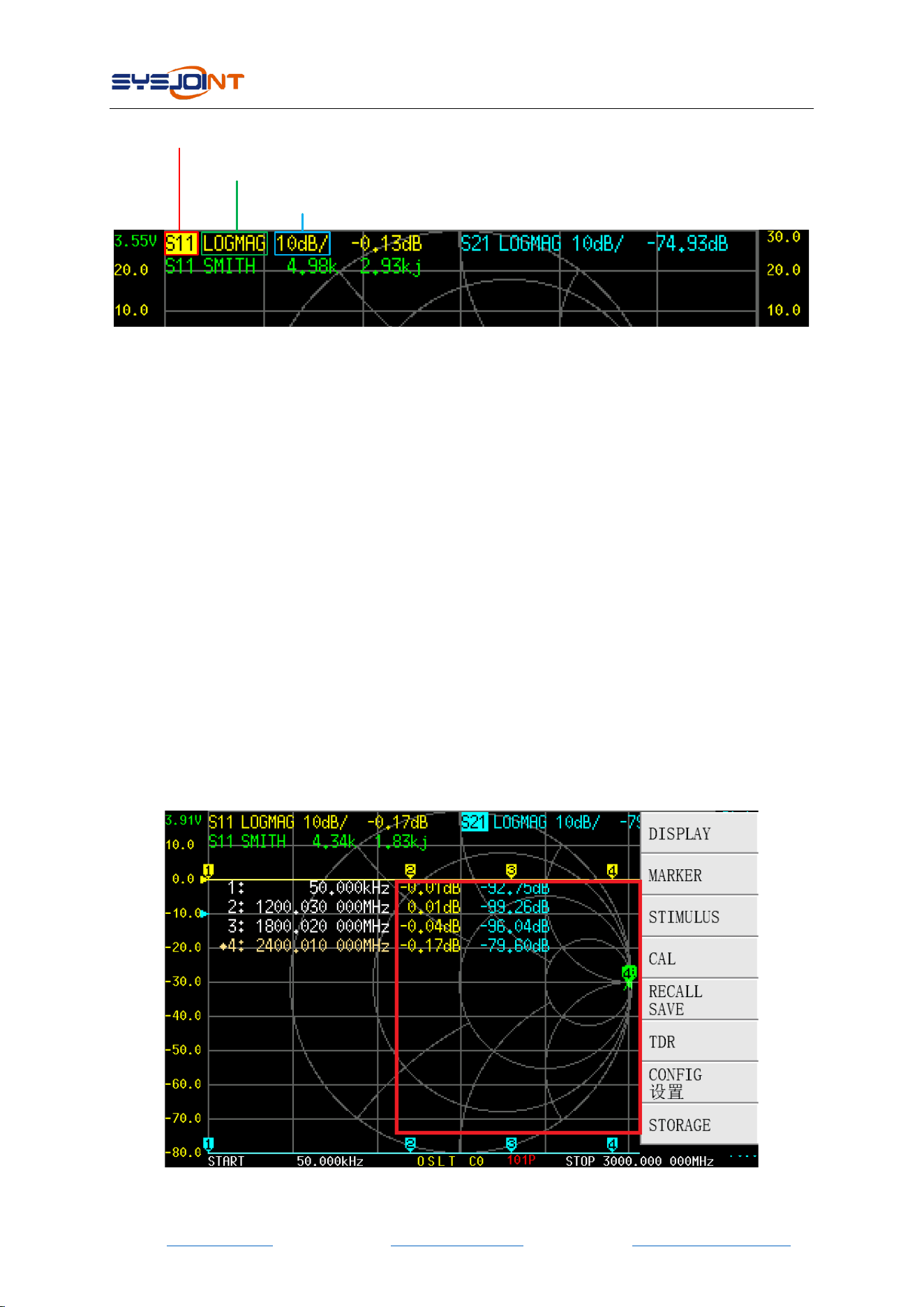
⑦ Trace status box
The status of each trace format and the value corresponding to the active marker are displayed.
For example, if the display is showing:S21 LOGMAG 10dB/ 0.03dB, read it as follows:
The cyan trace is current active
Channel: PORT2 (transmission)
Format: LOGMAG
Scale is 10dB/div
S21 value at current frequency is 0.03dB
Tap on any set of trace status box will activate the corresponding trace.
If the trace is active, tap on the specific region of the trace status box will trigger shortcuts:
Tap on “channel” region (e.g., S21) will quickly switch channel;
Tap on “format” region (e.g., LOGMAG) will quickly open the FORMAT menu;
Tap on “scale” region (e.g., 10dB/) will quickly open SCALE and REFERENCE POSITION menu.
NanoVNA-F V2 portable vector network analyzer user guide V2.0
©2016-2021 SYSJOINT Information Technology Co., Ltd.
- 7 -
scale region: tap here to quick open scale menu
format region: tap here to quick open format menu
channel region: tap here to quick switch channel
⑧ Battery voltage
The voltage of the built-in lithium battery is shown here. If the battery voltage is lower than 3.3V,
please charge the device.
⑨ Left ordinate
The left ordinate always shows the scale label of trace 0.
Tap on the area of left ordinate to quickly set the scale of trace 0.
⑩ Right ordinate
The right ordinate always shows the scale label of current active trace.
Tap on the area of right ordinate to quickly set the scale of current active trace.
⑪ Sweep points
Show sweep points.
3.2. Menu screen
NanoVNA-F V2 portable vector network analyzer user guide V2.0
©2016-2021 SYSJOINT Information Technology Co., Ltd.
- 8 -
The menu can be opened by the following operations:
⚫ Tap on the specific area of the screen (shown in the red frame above).
⚫ Press the middle button.
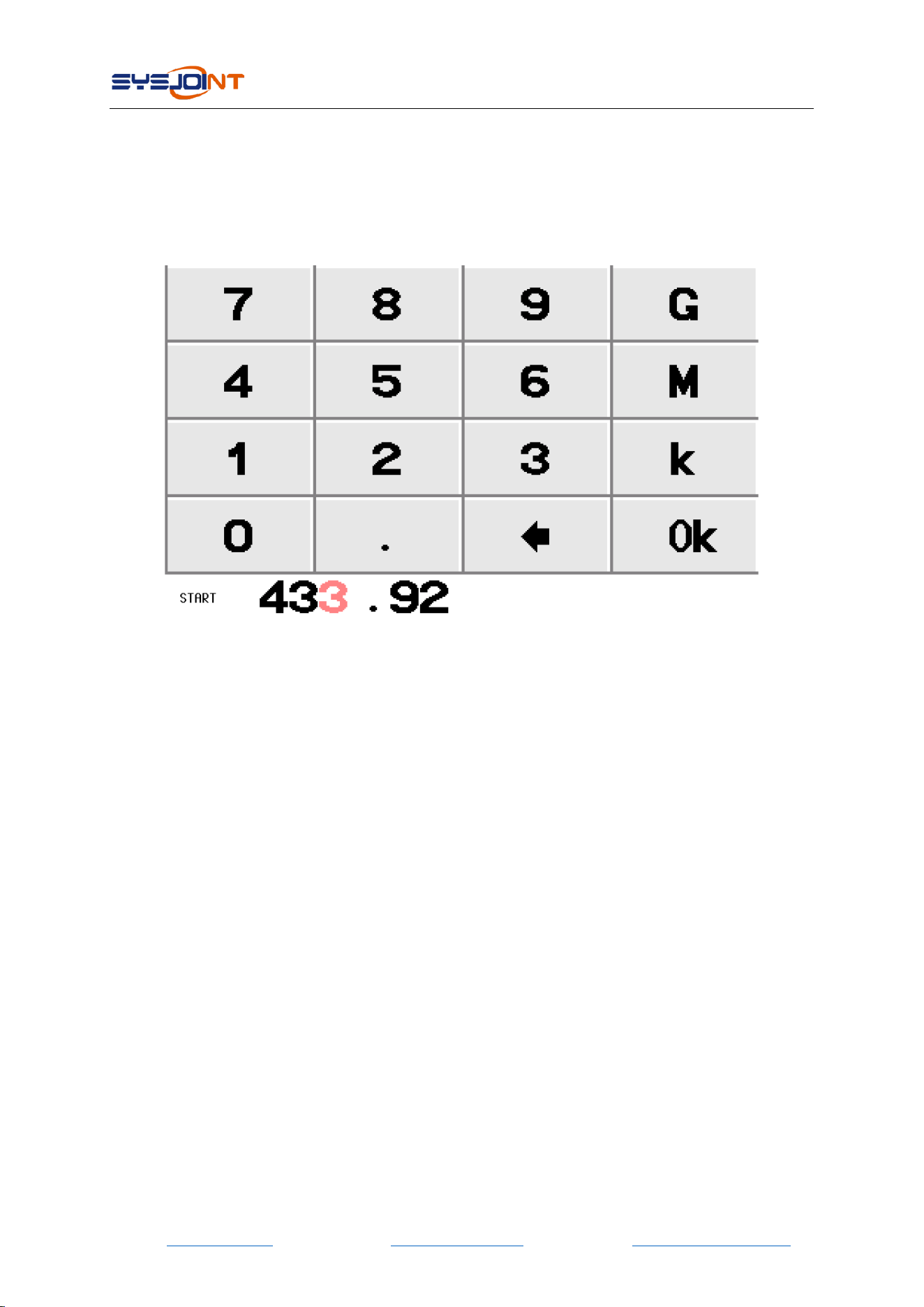
3.3. Keyboard screen
The virtual keyboard includes numeric keys, backspace key, unit key, ok key.
Backspace key is used to delete one character. When the input box is empty, tap on the
backspace key will close the keyboard.
Unit key(G, M, k) multiplies the current input by the corresponding unit and terminates input
immediately.
Ok key equals to x1, in case of ok, the entered value is set as it is.
E.g.,:100kHz :input 100 + k, or input 100000 + Ok;
433.92MHz :input 433.92 + M;
2.4GHz :input 2.4 + G;
4. Menus
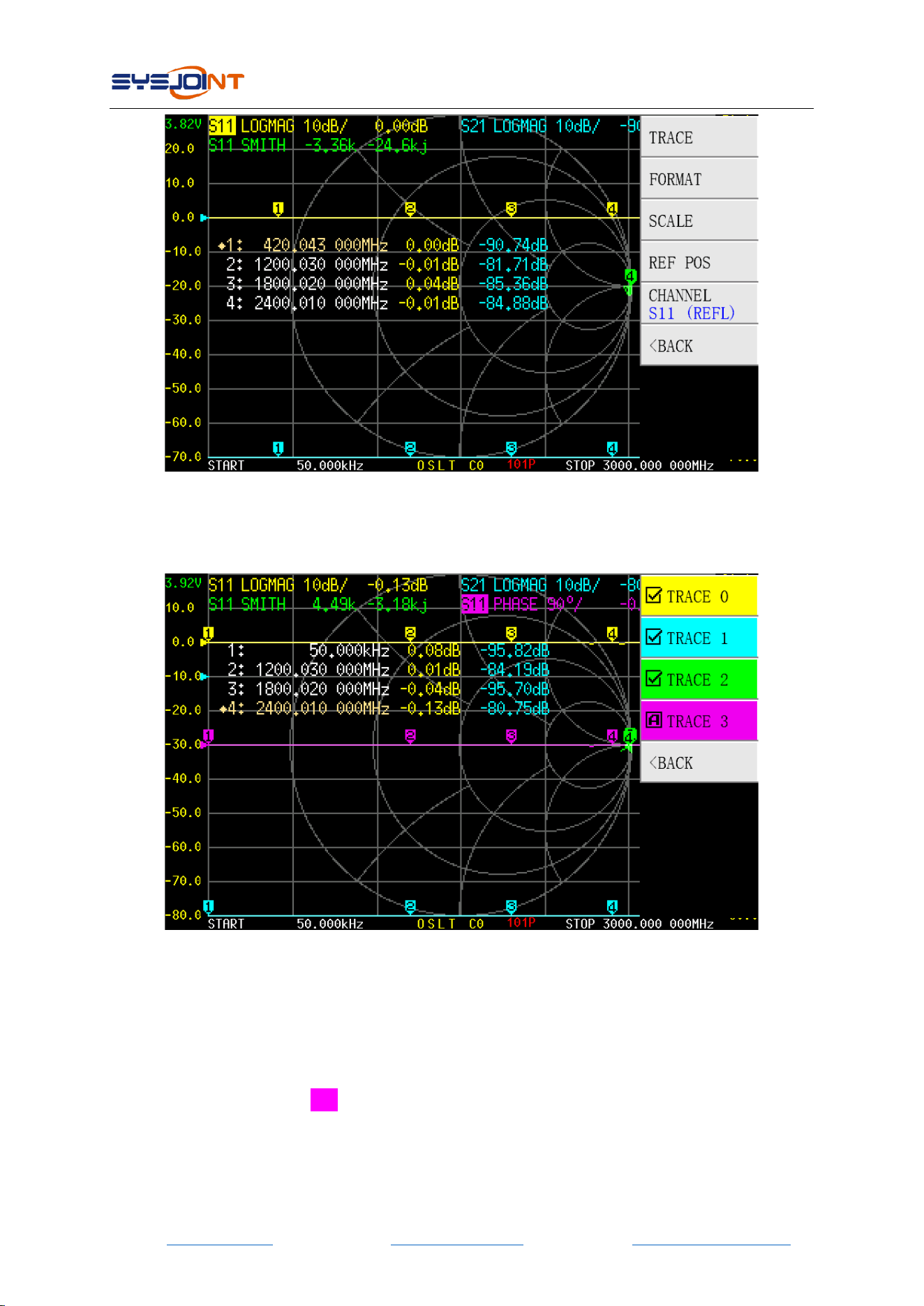
4.1. DISPLAY
【DSIPLAY】menu contains【TRACE】,【FORMAT】,【SCALE】,【REF POS】,【CHANNEL】
NanoVNA-F V2 portable vector network analyzer user guide V2.0
©2016-2021 SYSJOINT Information Technology Co., Ltd.
- 9 -
4.1.1 TRACE
【TRACE】menu contains【TRACE 0】,【TRACE 1】,【TRACE 2】,【TRACE 3】.
Tap on 【TRACE n】(e.g., 【TRACE 2】) will open and activate TRACE 2, and an □A marker will
appear ahead of “TRACE 2”. Tap on another menu item (e.g., 【TRACE 3】) will open and activate
TRACE 3, at this time, an □A marker will appear ahead of “TRACE 3”, and the □A marker ahead
of “TRACE 2” becomes , which means TRACE 2 and TRACE 3 are both opened and TRACE 3 is
current active.
When a trace is active, the channel region of the trace in trace status box will be highlighted, as
shown in the figure above, S11 is highlighted.
Tap on the menu item with □A marker will close the corresponding trace.

NanoVNA-F V2 portable vector network analyzer user guide V2.0
©2016-2021 SYSJOINT Information Technology Co., Ltd.
- 10 -
4.1.2 FORMAT
【FORMAT】is used to set the format of traces. There are formats of LOGMAG, PHASE, DELAY,
SMITH R+jX, SMITH R+L/C, SWR, Q FACTOR, POLAR, LINEAR, REAL, IMAG, RESISTANCE,
REACTANCE.
LOGMAG : the ordinate corresponds to logarithmic amplitude and the abscissa
corresponds to frequency.
PHASE:the ordinate corresponds to phase and the abscissa corresponds to the frequency.
DELAY:the ordinate corresponds to group delay and the abscissa corresponds to
frequency. Only meaningful for S21.
SMITH R+jX:show impedance with Smith chart. Impedance is displayed in the form of
R+jX. Only meaningful for S11.
SMITH R+L/C: show impedance with Smith chart. Impedance is displayed in the form of
R+L/C, where R is the resistance value and L/C is the equivalent inductance or capacitance value.
Only meaningful for S11.
SWR:the ordinate corresponds to VSWR and the abscissa corresponds to frequency. Only
meaningful for S11.
Q FACTOR:the ordinate corresponds to Q factor, and the abscissa corresponds to
frequency.
POLAR:show impedance in polar coordinates. Only meaningful for S11.
LINEAR:the ordinate corresponds to linear amplitude, and the abscissa corresponds to
frequency.
REAL:the ordinate corresponds to the real part of S parameter, and the abscissa
corresponds to frequency.
IMAG:the ordinate corresponds to the imaginary part of S parameter, and the abscissa
corresponds to frequency.
RESISTANCE:the ordinate corresponds to resistance, and the abscissa corresponds to
frequency.
REACTANCE:the ordinate corresponds to reactance, and the abscissa corresponds to
frequency.
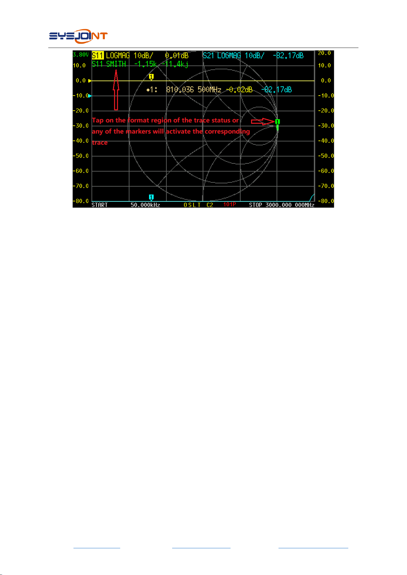
There are 3 ways to activate a trace:
(1)【 DISPLAY】→【TRACE】→【TRACE n】.
(2)Tap on the format region of the corresponding trace in the trace status box.
(3)Tap on any markers with the same color to the trace.
NanoVNA-F V2 portable vector network analyzer user guide V2.0
©2016-2021 SYSJOINT Information Technology Co., Ltd.
- 11 -
4.1.3 SCALE
【SCALE】is used to set the scale of the ordinate (not applicable to SMITH and POLAR formats).
4.1.4 REF POS
【REF POS】is used to set the reference position of the trace (not applicable to SMITH and
POLAR formats). Ref pos is set to 7 by default, which corresponds to the 7th horizontal axis
counting from bottom to top (0 corresponds to the bottom horizontal axis). Ref pos can be set
to any integer.
4.1.5 CHANNEL
Tap on【CHANNEL】to switch the channel of current active trace.
4.2. MARKER
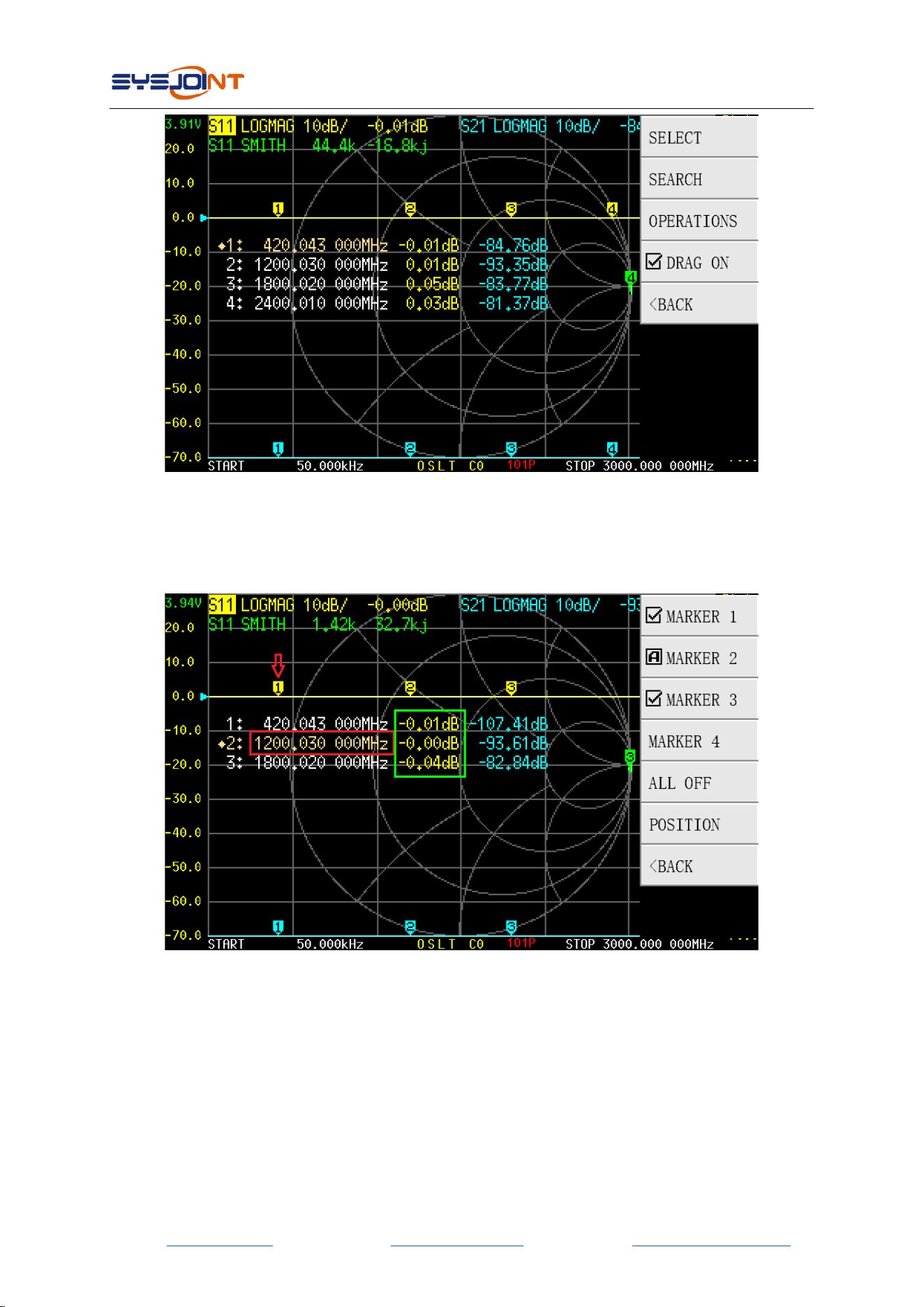
【MARKER】menu contains【SELECT】,【SEARCH】,【OPERATIONS】,【DRAG ON】.
NanoVNA-F V2 portable vector network analyzer user guide V2.0
©2016-2021 SYSJOINT Information Technology Co., Ltd.
- 12 -
4.2.1 SELECT
【SELECT】menu contains【MARKER 1】,【MARKER 2】,【MARKER 3】,【MARKER 4】,【ALL
OFF】,【POSITION】.
Tap on 【MARKER n】 (e.g., 【MARKER 2】) will open and activate MARKER 2, and an □A marker
will appear ahead of “MARKER 2”. Tap on another menu item (e.g., 【MARKER 3】) will open and
activate MARKER 3, at this time, an □A marker will appear ahead of “MARKER 3”, and the □A
marker ahead of “MARKER 2” becomes , which means MARKER 2 and MARKER 3 are both
opened and MARKER 3 is current active.
Tap on the menu item with □A will close the corresponding marker.
The marker can be moved with the buttons only when it is active.
There are two ways to quickly activate a marker:
NanoVNA-F V2 portable vector network analyzer user guide V2.0
©2016-2021 SYSJOINT Information Technology Co., Ltd.
- 13 -
(1)Tap on the marker directly, as shown by the red arrow of the figure above
(recommend to operate with a stylus).
(2)Tap on the frequency value region of the corresponding marker in the marker table, as
shown in the red box of the above (recommend to operate with a stylus).
【ALL OFF】is used to turn off all markers at once.
【POSITION】is used to adjust the position of the marker table on screen. The marker table can
be moved up and down to avoid occluding traces and markers.
It is possible to move the marker table by dragging: make sure that【DRAG ON】is enabled, and
then tap on the marker value region (as shown in the green box of the figure above) and hold
for more than 1 second, then you can drag and move the marker table freely (recommend to
operate with a stylus).
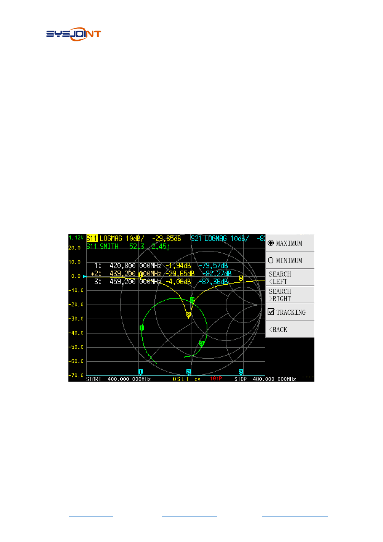
4.2.2 SEARCH
【SEARCH】menu contains 【MAXIMUM】,【MINIMUM】,【SEARCH < LEFT】,【SEARCH >
RIGHT】,【TRACKING】,and all the functions are effective for the currently active marker.
【TRACKING】is used to automatically track the maximum or minimum value of the trace. As
shown in the figure above, if you want MARKER 2 to automatically track the minimum value of
the S11 LOGMAG trace, firstly you should activate MARKER 2, and then tap on【MINIMUM】,
and finally turn on【TRACKING】. After doing that, MARKER 2 will automatically move to the
valley point of the S11 LOGMAG trace after each sweep.
4.2.3 OPERATIONS
【OPERATIONS】menu contains【>START】,【>STOP】,【>CENTER】,【>SPAN】.
【>START】: Set the frequency of the current active marker as the start frequency.
NanoVNA-F V2 portable vector network analyzer user guide V2.0
©2016-2021 SYSJOINT Information Technology Co., Ltd.
- 14 -
【>STOP】: Set the frequency of the current active marker as the stop frequency.
【>CENTER】: Set the frequency of the current active marker as the center frequency.
【>SPAN】: Set the frequency range between the current active marker and the next marker as
the span. If there are no other markers behand the current active marker, the span will be set to
zero.
4.2.4 DRAG ON
Enable/disable the draggable characteristic of marker table.
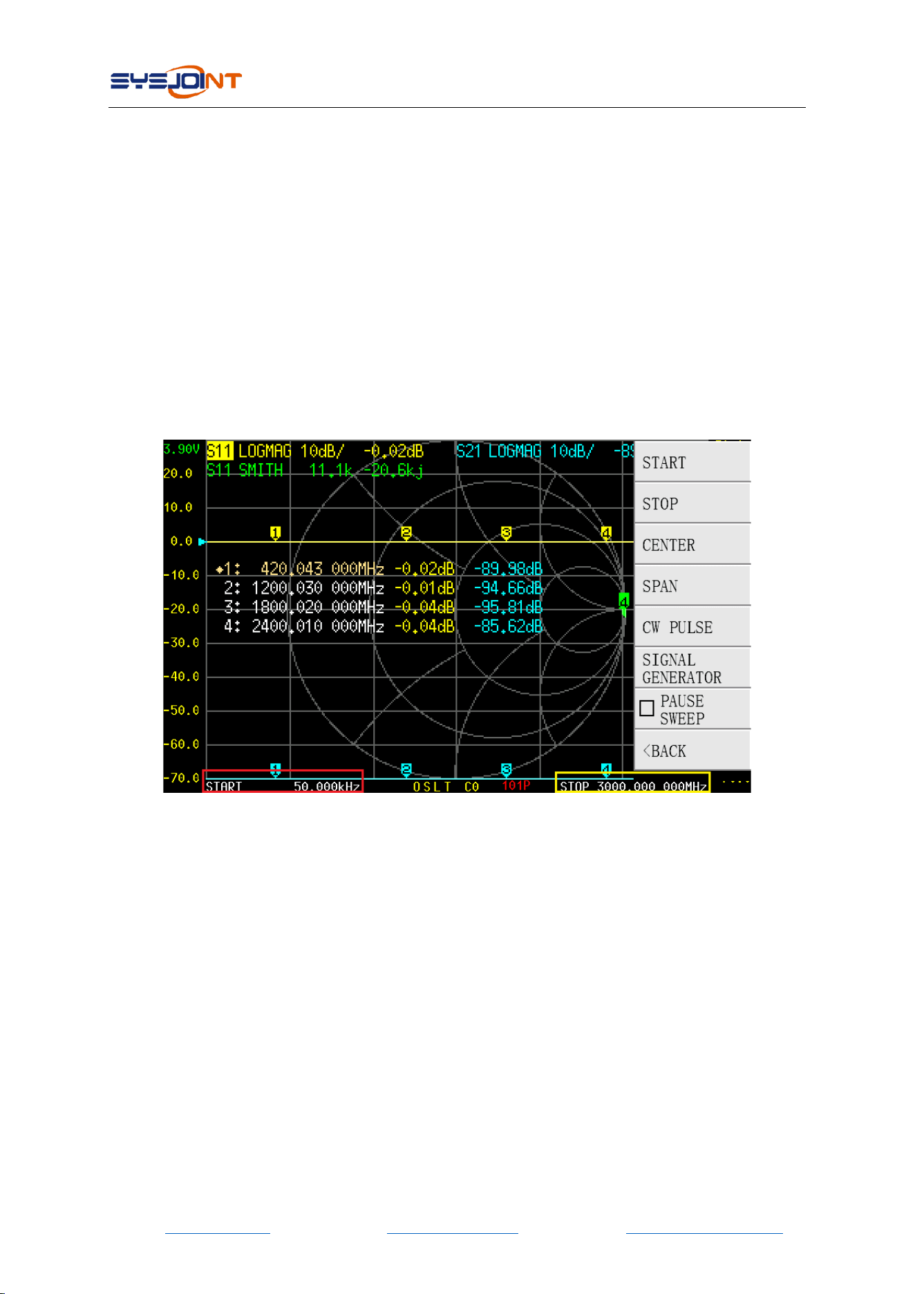
4.3. STIMULUS
【STIMULUS】menu contains【START】,【STOP】,【CENTER】,【SPAN】,【CW PULSE】, 【SIGNAL
GENERATOR】,【PAUSE SWEEP】.
4.3.1 START
Tap on【START】to set the start frequency.
You can also tap on the red box area of the above figure to quickly set the start frequency.
4.3.2 STOP
Tap on【STOP】to set the stop frequency.
You can also tap on the yellow box area of the above figure to quickly set the stop frequency.
4.3.3 CENTER
Tap on【CENTER】to set the center frequency.
You can also tap on the red box area of the above figure to quickly set the center frequency.
NanoVNA-F V2 portable vector network analyzer user guide V2.0
©2016-2021 SYSJOINT Information Technology Co., Ltd.
- 15 -
4.3.4 SPAN
Tap on【SPAN】to set the frequency span.
You can also tap on the yellow box area of the above figure to quickly set the frequency span.
4.3.5 CW PULSE
Tap on【CW PULSE】to set the CW pulse frequency.
You can also tap on the red box area of the above figure to quickly set the CW pulse frequency.
Please note that in this mode the output of PORT 1 is pulse signal, not continuous wave.
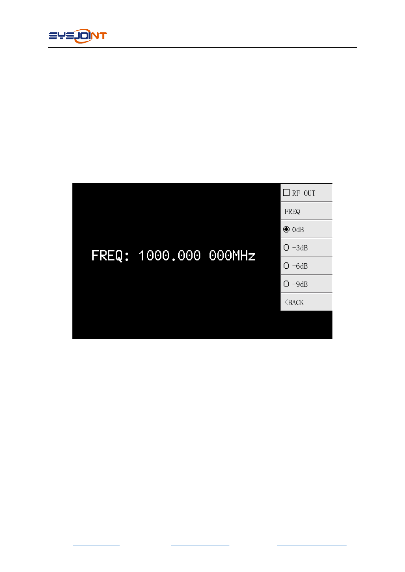
4.3.6 SIGNAL GENERATOR
【SIGNAL GENERATOR】NanoVNA-F V2 supports simple signal generator function, which can
be set as a single-frequency continuous wave generator with a frequency range from 50kHz to
4400MHz. RF power is adjustable above 135MHz.
【RF OUT】:Turn on/off the RF output.
【FREQ】:Set the frequency.
【0dB】:Output power attenuated 0dB.
【-3dB】:Output power attenuated 3dB.
【-6dB】:Output power attenuated 6dB.
【-9dB】:Output power attenuated 9dB.
4.3.7 PAUSE SWEEP
Tap on【PAUSE SWEEP】to pause sweep, tap again to resume sweep.
4.4. CAL
【CAL】menu contains【CALIBRATE】,【RESET】,【APPLY】.
NanoVNA-F V2 portable vector network analyzer user guide V2.0
©2016-2021 SYSJOINT Information Technology Co., Ltd.
- 16 -
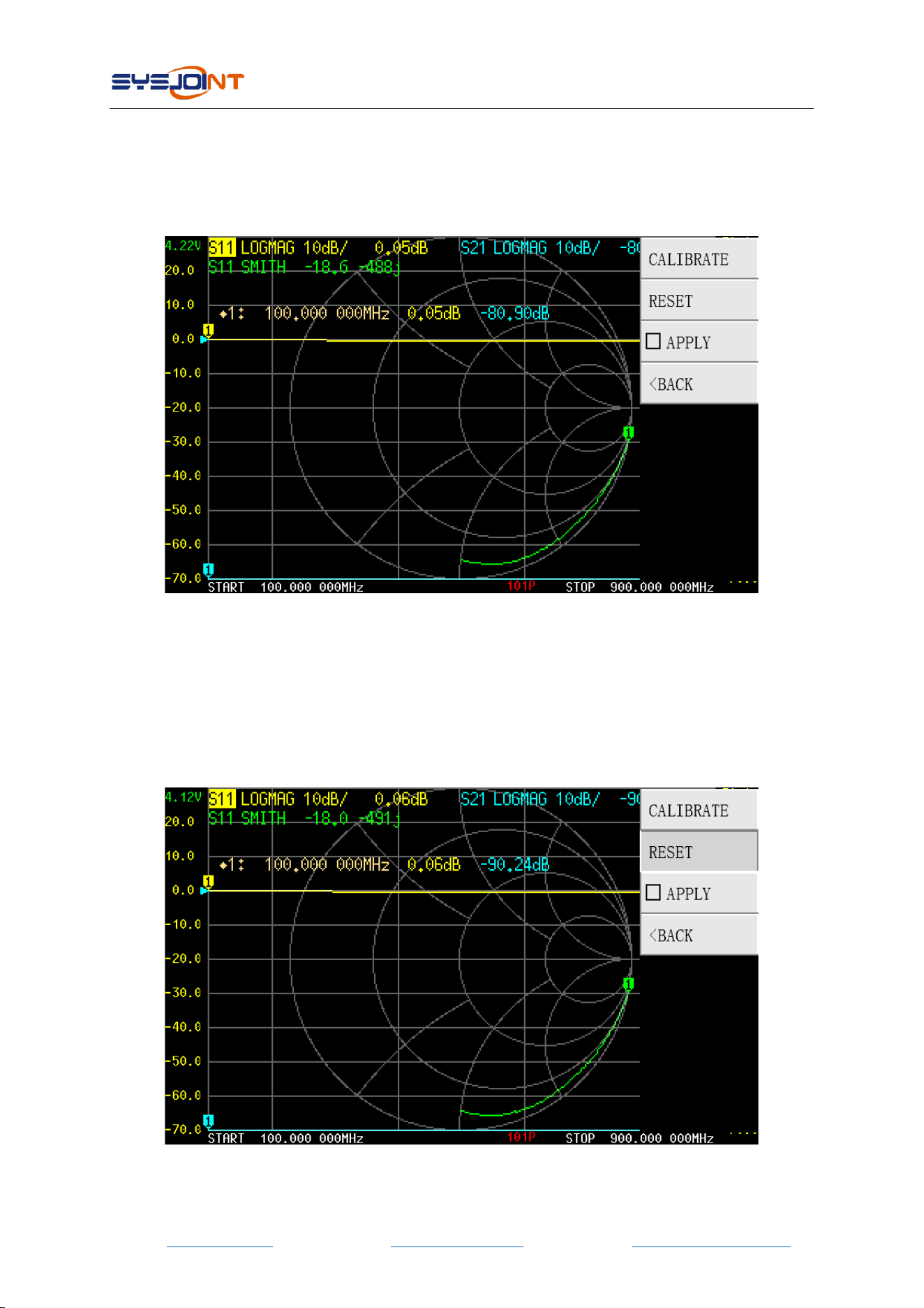
4.4.1 APPLY
【APPLY】is turned on by default, indicating that the calibration data has been applied. Tap on
【APPLY】to turn it off. After doing that, the calibration status Cn at the bottom of the main
screen will disappear, indicating that the measurement result is uncorrected.
4.4.2 RESET
Tap on【RESET】to clear the calibration data in the memory. After doing that, the calibration
status OSLT Cn at the bottom of the main screen will disappear, but the calibration data stored
in the internal FLASH will not be cleared. You can call back the calibration data to the memory
by
【RECALL/SAVE】→【RECALL】→【RECALL n】
NanoVNA-F V2 portable vector network analyzer user guide V2.0
©2016-2021 SYSJOINT Information Technology Co., Ltd.
- 17 -
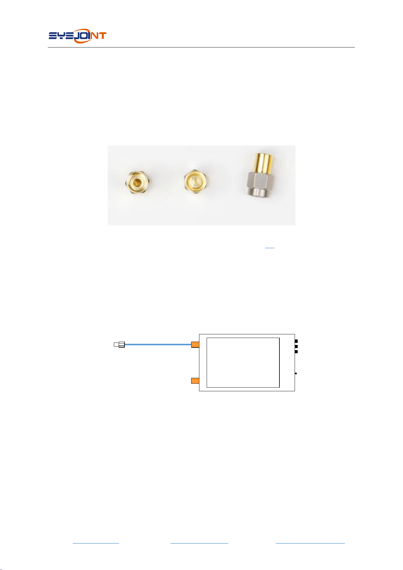
4.4.3 CALIBRATE
Tap on【CALIBRATE】to perform calibration. The following accessories need to be prepared
before calibration:
(1)SMA OPEN kit;
(2)SMA SHORT kit;
(3)SMA LOAD kit;
(4)SMA-JJ RG405 cable;
(5)SMA straight through adapter (optional);
OPEN SHORT LOAD
Firstly, you need to set an appropriate frequency range, see section 4.3 for detail.
Tap on【CALIBRATE】to enter the calibration interface, and perform the calibration according to
the following steps:
STEP ①
Connect the OPEN kit to PORT1 or the end of the cable connected to PORT1, as shown in the
figure below:
NanoVNA-F V2
Cable (optional)
Calibration kit
Tap on【OPEN】, the device emits a beep, and the menu turns gray and is inoperable. Wait for
2-3 seconds, the device emits a beep again, an □A marker will appear ahead of “OPEN”, and a
letter "O" appears at the bottom of the screen, indicating that open calibration is finished.
NanoVNA-F V2 portable vector network analyzer user guide V2.0
©2016-2021 SYSJOINT Information Technology Co., Ltd.
- 18 -
NOTE: usually we need to connect the DUT to VNA with cables, at this time, the cable becomes
a part of the measurement system, and the end of the cable should be treated as the VNA port
during calibration.
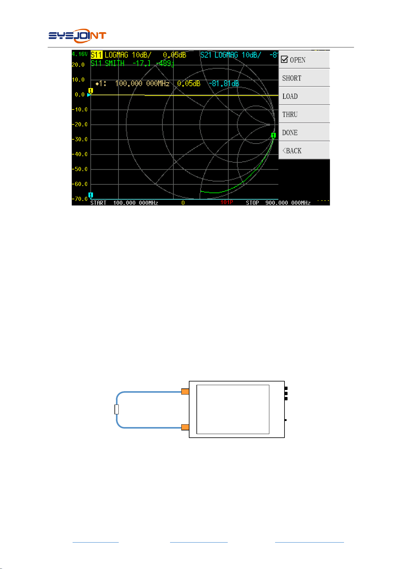
STEP ②
Connect the SHORT kit to PORT1 or the end of the cable connected to PORT1, tap on【SHORT】
to complete the short calibration.
STEP ③
Connect the LOAD kit to PORT1 or the end of the cable connected to PORT1, tap on【LOAD】
to complete the load calibration.
STEP ④
Connect PORT1 and PORT2 with cable and adaptor (optional), as shown in the figure below,
then tap on【THROUGH】to complete the through calibration.
NanoVNA-F V2
Cable
Adaptor (optional)
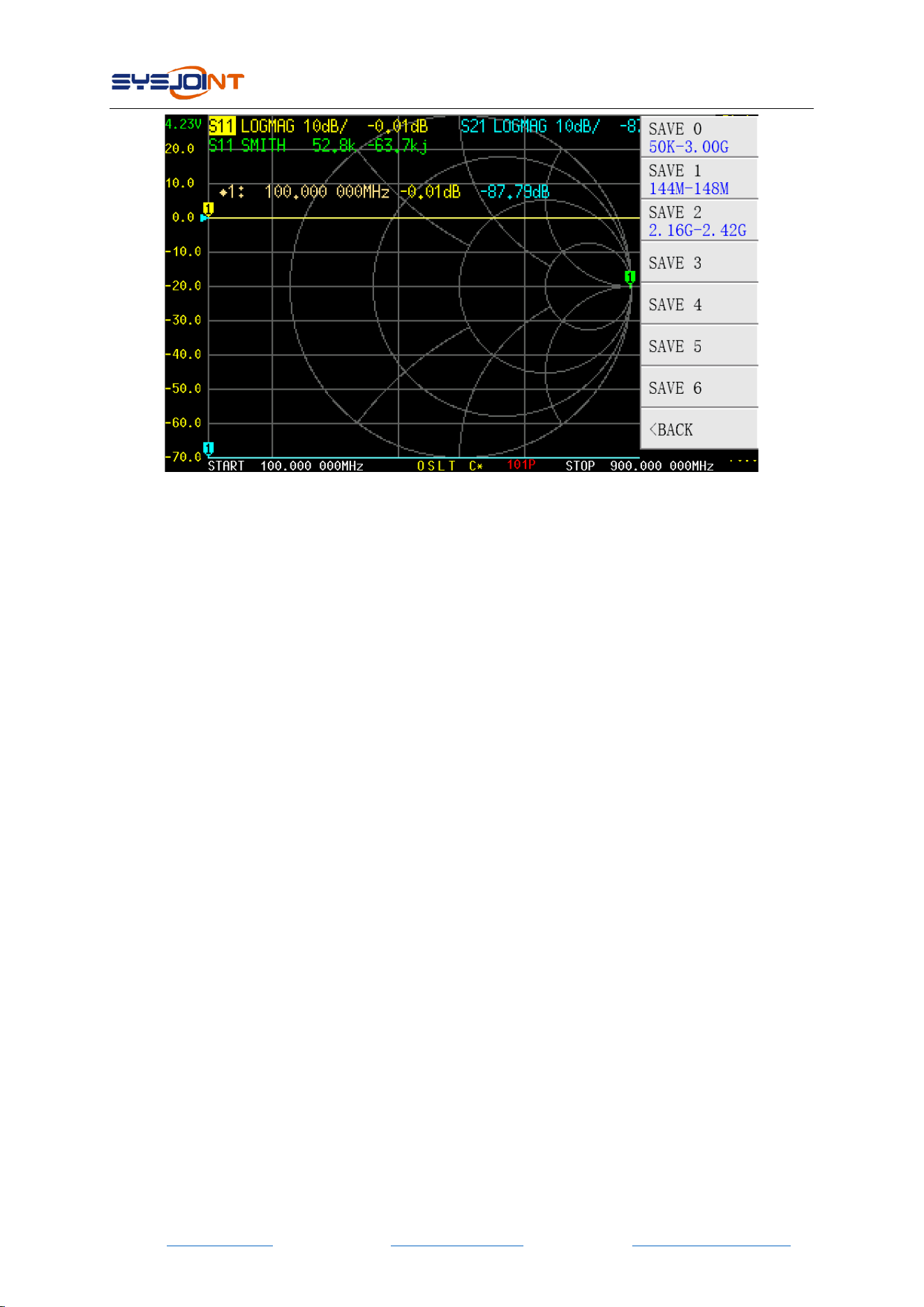
STEP ⑤
Tap on【DONE】, OSLT C* will appear at bottom of the screen, indicating that the calibration
data has been generated but not yet saved. The save menu will appear on the right side of the
screen at the same time. Tap on【SAVE n】to save the calibration data, and the frequency range
of the calibration data will be display on the menu item.
NanoVNA-F V2 portable vector network analyzer user guide V2.0
©2016-2021 SYSJOINT Information Technology Co., Ltd.
- 19 -
When properly calibrated, the VNA device should have the following characteristics:
(1) When PORT1 is open-circuited, the S11 Smith trace converges on the far-right side of the
Smith circle, the S11 LOGMAG trace is near 0dB, for S21 LOGMAG trace, the lower the better.
(2) When PORT1 is short-circuited, the S11 Smith trace converges on the far-left side of the
Smith circle, the S11 LOGMAG trace is near 0dB, for S21 LOGMAG trace, the lower the better.
(3) When PORT1 is connected to a 50-ohm load, the S11 Smith traces converge at the center of
the Smith circle. The lower the S11 and S21 LOGMAG trace, the better.
(4) When PORT1 and PORT2 connected by a cable, the S11 Smith trace is near the center of the
Smith circle, and the S21 LOGMAG trace is near 0dB. For S11 LOGMAG trace, the lower the
better.
4.5. RECALL/SAVE
【RECALL/SAVE】menu contains【RECALL】and【SAVE】.
4.5.1 RECALL
Tap on【RECALL n】to recall calibration data and settings stored in slot n. The marker indicates
which calibration data has been recalled.
4.5.2 SAVE
Tap on【SAVE n】to save calibration data and settings to one of 7 save slots.
NanoVNA-F V2 portable vector network analyzer user guide V2.0
©2016-2021 SYSJOINT Information Technology Co., Ltd.
- 20 -
4.6. TDR
NanoVNA-F V2 can be used as a time domain reflectometry, which is only meaningful for S11.
【TDR】menu contains【TDR ON】,【LOW PASS IMPULSE】,【LOW PASS STEP】,【BANDPASS】,
【WINDOW】,【VELOCITY FACTOR】.
Tap on【TDR ON】to enable TDR. Tap again to disable.
The relationship between time domain and frequency domain is as follows.
● Increasing the maximum frequency increases the time resolution.
● The shorter the measurement frequency interval (e.g. the lower the maximum
frequency), the longer the maximum time length.
For this reason, the maximum time length and time resolution are in a trade-off relationship. In
other words, the time length is the distance.
● If you want to increase the maximum measurement distance, you need to reduce the
frequency spacing (frequency span / sweep points).
● If you want to measure the distance accurately, you need to increase the frequency
span.
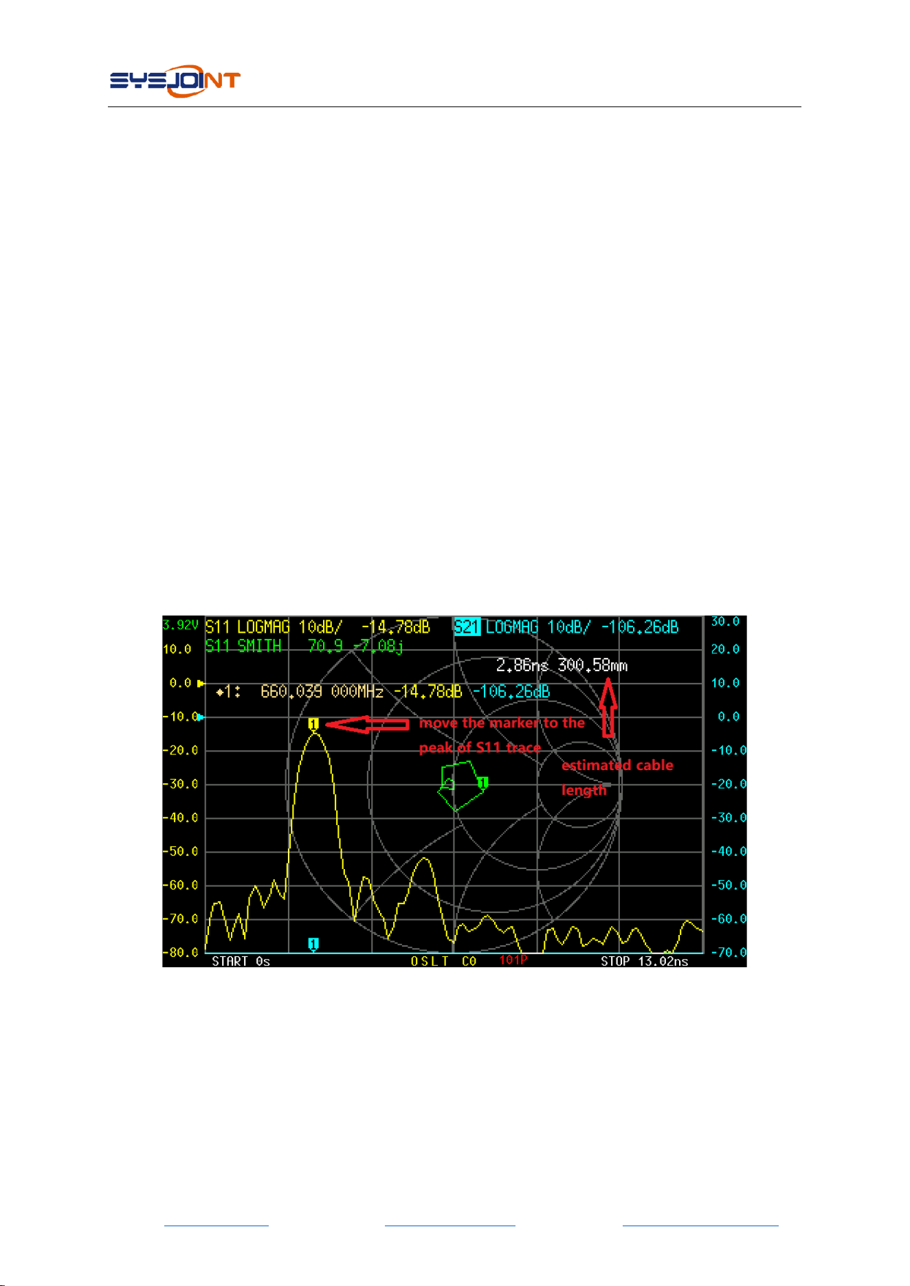
Connect a cable to PORT1, keep the other end of the cable open or short, move the marker to
the peak of S11 trace, and the estimated cable length will be displayed on the screen.
There are 3 kinds of digital processing mode available:【LOW PASS IMPULSE】,【 LOW PASS
STEP】,【BANDPASS】, and default setting is【BANDPASS】.
The range that can be measured is a finite number, and there is a minimum frequency and a
maximum frequency. A window can be used to smooth out this discontinuous measurement
data and reduce ringing.
NanoVNA-F V2 portable vector network analyzer user guide V2.0
©2016-2021 SYSJOINT Information Technology Co., Ltd.
- 21 -
There are three levels of windowing:【MINIMUM】,【 NORMAL】,【MAXIMUM】, and default
setting is【NORMAL】.
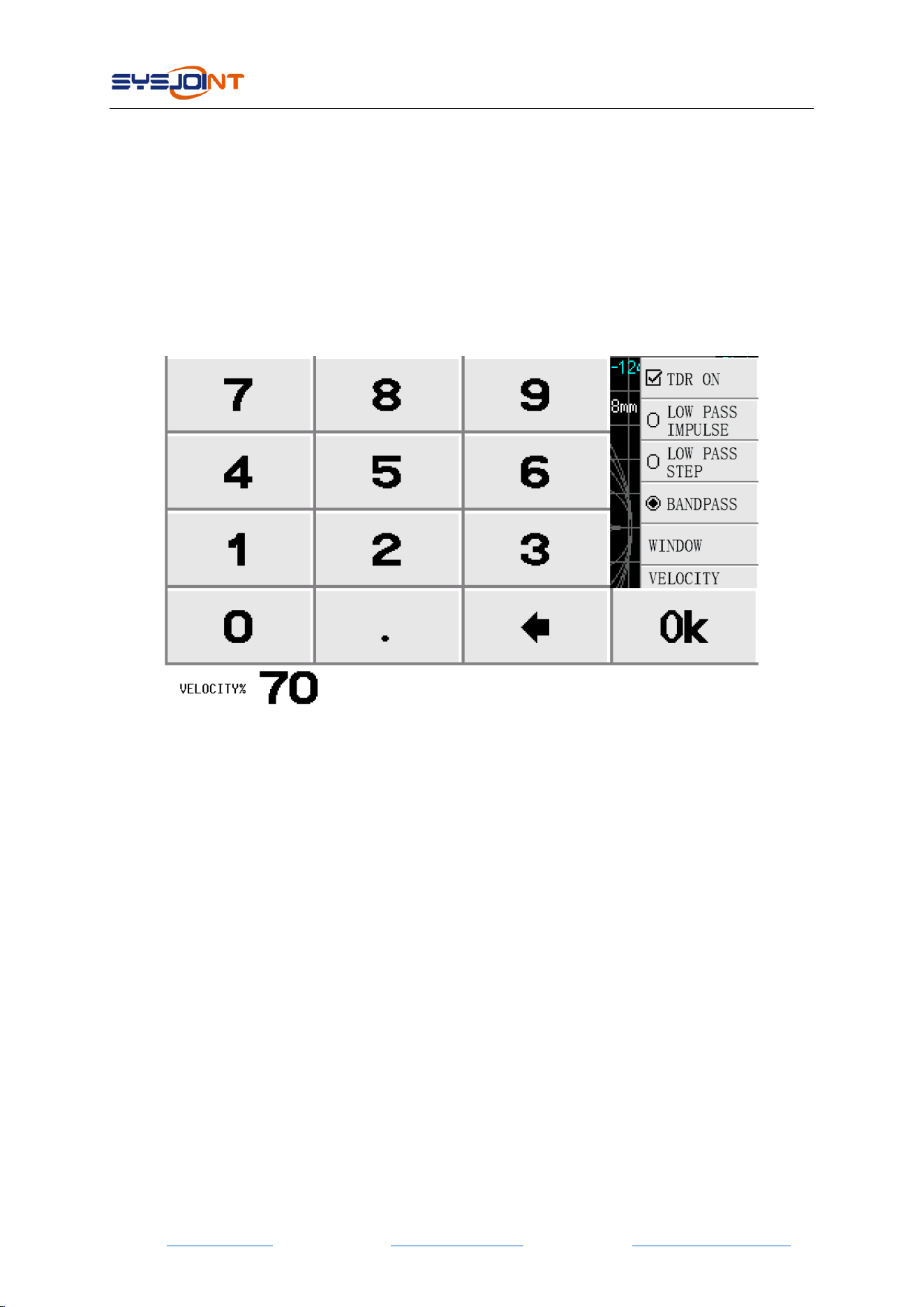
Velocity factor is defined as the ratio of the transmission speed of electromagnetic waves in the
transmission line to the transmission speed of electromagnetic waves in vacuum.
Tap【VELOCITY FACTOR】to set the velocity factor. E.g. the typical velocity factor of RG405 cable
is 0.7, you should input 70 via the virtual keyboard and end up with Ok, then the velocity factor
will be set to 70%.
NOTE: Use a lower frequency to measure a longer length and a higher frequency to measure a
shorter length and adjust accordingly for accurate results.
4.7. CONFIG
【CONFIG】 menu contains 【ELECTRICAL DELAY】,【L/C MATCH】,【SWEEP POINTS】,
【TOUCH TEST】,【LANGSET】,【ABOUT】,【BRIGHTNESS】.
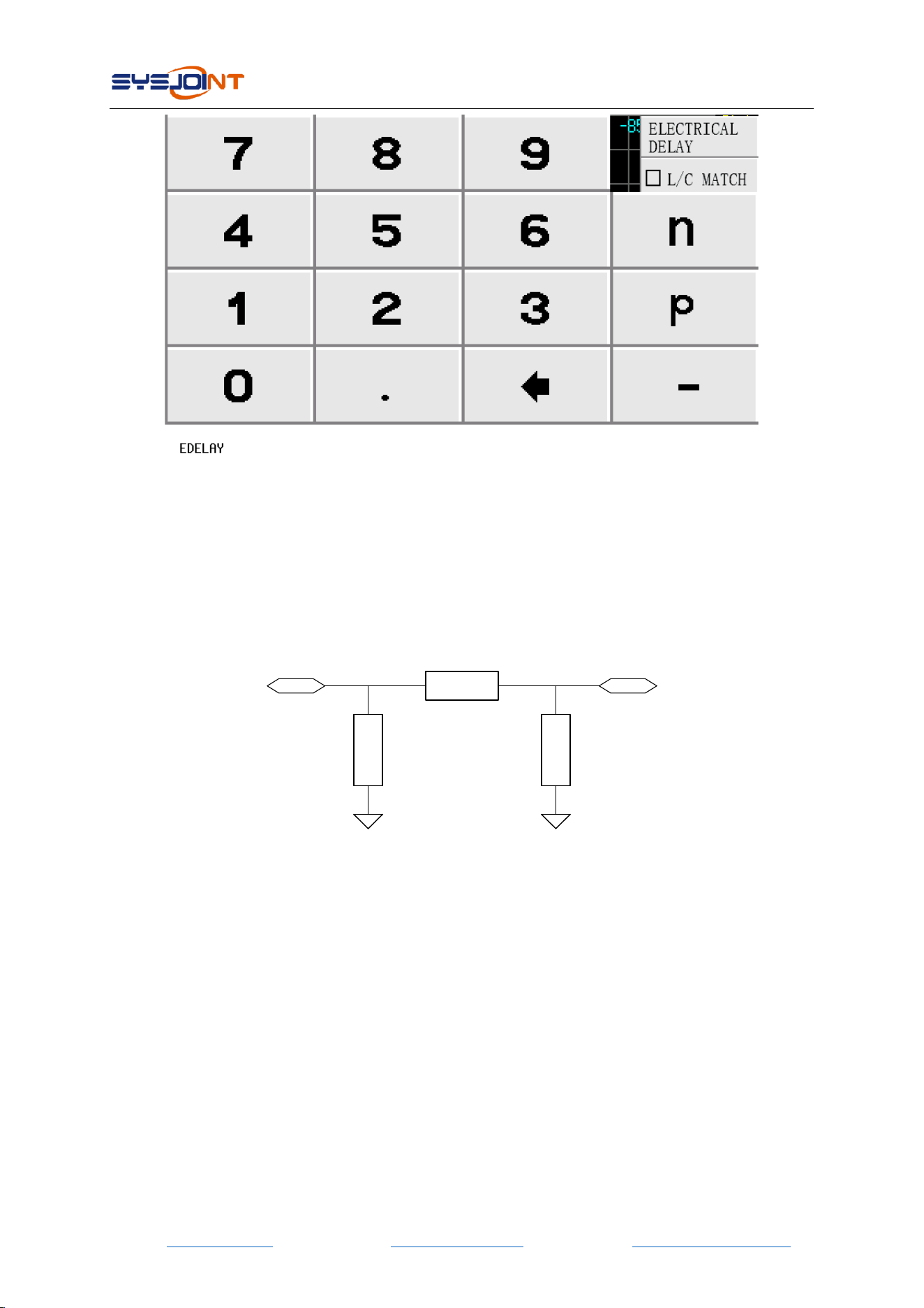
4.7.1 ELECTRICAL DELAY
【ELECTRICAL DELAY】is used to set a delay time in nanoseconds (ns) or picoseconds (ps) to
compensate for the delay introduced by connectors or cables.
NanoVNA-F V2 portable vector network analyzer user guide V2.0
©2016-2021 SYSJOINT Information Technology Co., Ltd.
- 22 -
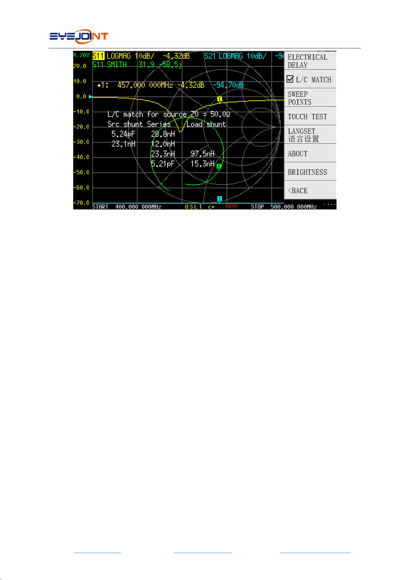
4.7.2 L/C MATCH
NanoVNA-F V2 supports automatic calculation of L/C matching parameters, matching the load
impedance to the source 50ohm impedance.
The structure of L/C matching network is shown in the figure below:
Src shunt Load shunt
Series
Source Load
Example:
The measured load impedance is 31.9-58.5j, and VNA automatically generates four groups of
available matching parameters:
1. 5.24pF capacitor for source shunt and 28.8nH inductor in series;
2. 23.1nH inductor for source shunt and 12nH inductor in series;
3. 97.5nH inductor for load shunt and 23.3nH inductor in series;
4. 15.3nH inductor for load shunt and 5.21pF capacitor in series.
NanoVNA-F V2 portable vector network analyzer user guide V2.0
©2016-2021 SYSJOINT Information Technology Co., Ltd.
- 23 -
4.7.3 SWEEP POINTS
Sweep points are configurable from 11 to 201.
4.7.4 TOUCH TEST
【TOUCH TEST】is used to test whether the touch screen is normal. Press any button to exit the
test.
4.7.5 LANGSET
Set language: Chinese or English.
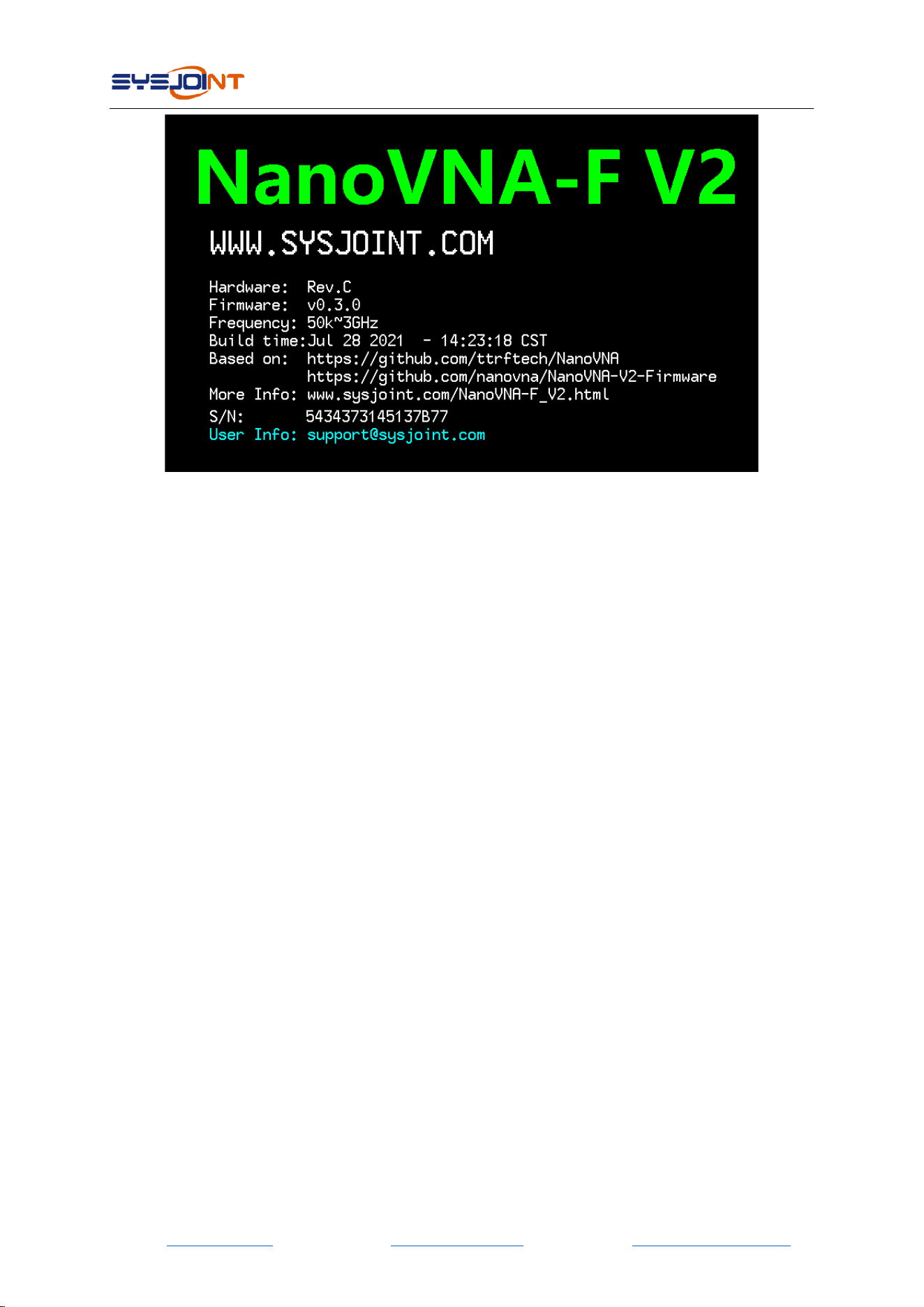
4.7.6 ABOUT
You can check the hardware version, firmware version, serial number and supporting
information, etc.
Each NanoVNA-F V2 device has a unique serial number, SYSJOINT provides after-sales service
to customers based on this serial number.
NanoVNA-F V2 portable vector network analyzer user guide V2.0
©2016-2021 SYSJOINT Information Technology Co., Ltd.
- 24 -
4.7.7 BRIGHTNESS
The backlight brightness is adjustable in five levels: 100%、80%、60%、40%、20%.
4.8. STORAGE
【STORAGE】menu contains【S1P】,【S2P】,【LIST】.
4.8.1 S1P
S11 test results can be stored to the internal memory of NanoVNA-F V2 in the form of S1P files,
which can be exported to PC with USB cable.
4.8.2 S2P
S11 and S21 test results can be stored to the internal memory of NanoVNA-F V2 in the form of
S2P files, which can be exported to PC with USB cable.
4.8.3 LIST
List all the SNP files stored in the device.
5. User Defined Information
NanoVNA-F V2 supports displaying user-defined information on the boot screen. The setting
method is as follows:
1. Create a text file named ‘callsign.txt’ on PC;
2. Open ‘callsign.txt’ and input the string which you want to be displayed on the boot screen
(printable ASCII characters only, e.g., support@sysjoint.com). The maximum string length is 50.
NanoVNA-F V2 portable vector network analyzer user guide V2.0
©2016-2021 SYSJOINT Information Technology Co., Ltd.
- 25 -
3. Make NanoVNA-F V2 enter virtual u-disk mode, and copy ‘callsign.txt’ into the virtual u-disk.
4. Restart NanoVNA-F V2.
6. PC Software
PC software download: http://www.sysjoint.com/file/Nanovna-Saver-0.3.8-by-SYSJOINT.exe
For Win10 system, you do not need to install the driver.
For Win8 and earlier versions of the Windows system, you need to install the driver:
https://www.st.com/en/development-tools/stsw-stm32102.html
PC software provided by SYSJOINT only supports Windows system, Linux or MacOS version of
the PC software is available from: https://github.com/NanoVNA-Saver/nanovna-saver/releases
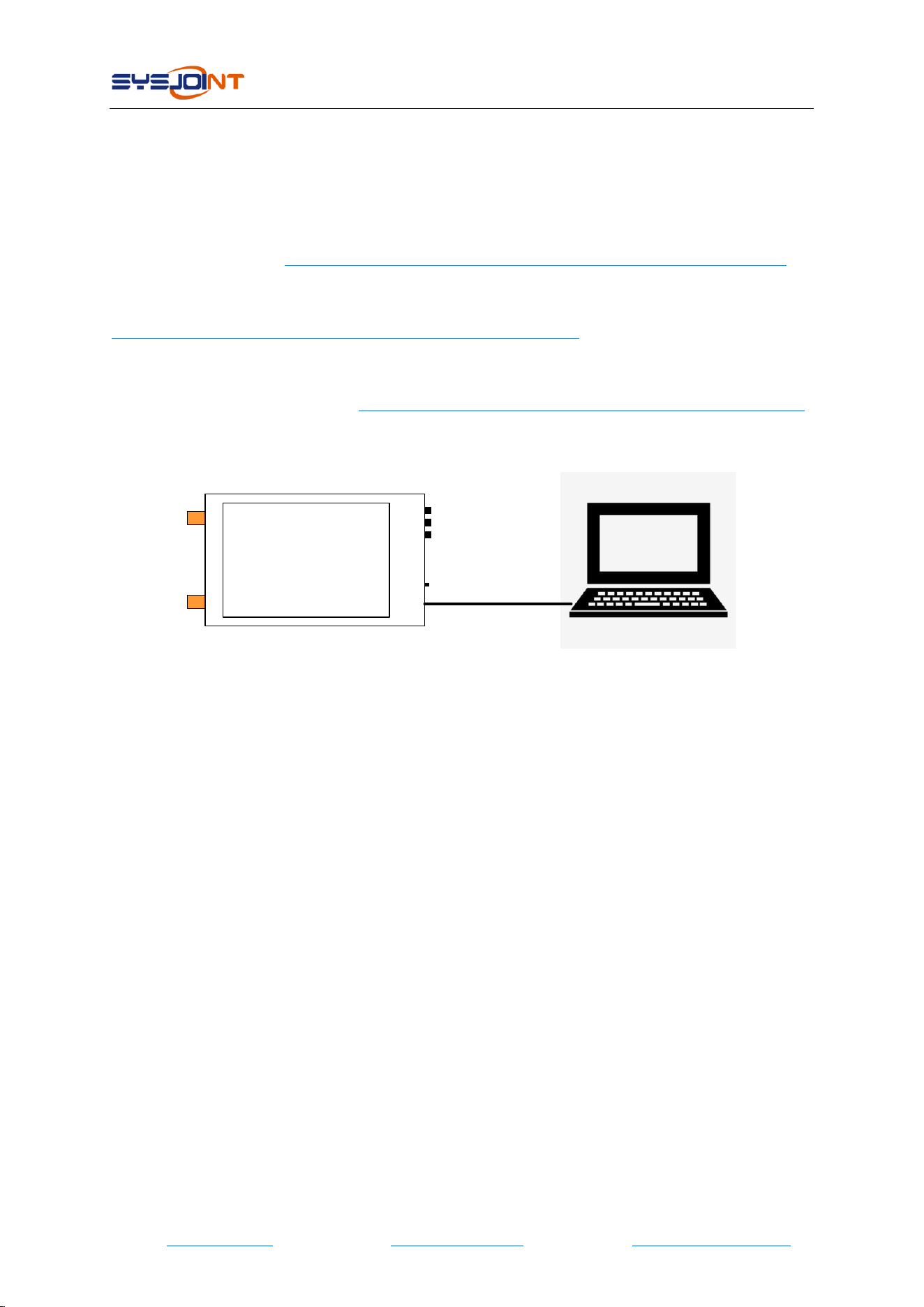
Connect NanoVNA-F V2 to your PC with the USB Type-C cable, as shown in the figure below:
NanoVNA-F V2
USB type-c
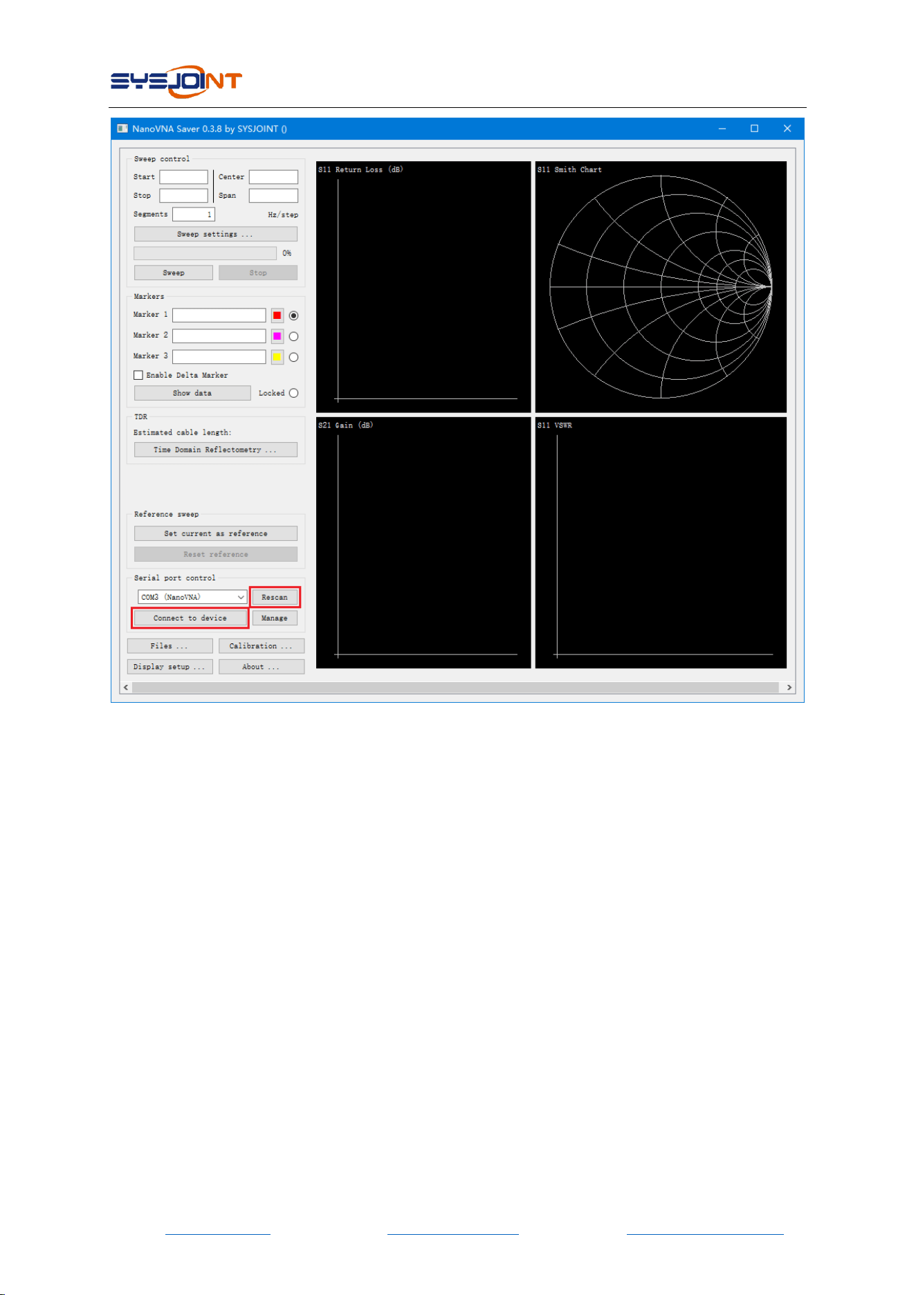
Double click “nanovna-saver.exe” to run the PC software, and select the correct COM port. If
there is no COM port detected, please click 【Rescan】.
After selecting the correct COM port, click【connect to device】to connect the device to PC.
NanoVNA-F V2 portable vector network analyzer user guide V2.0
©2016-2021 SYSJOINT Information Technology Co., Ltd.
- 26 -
Through the PC software, you can set the start and stop frequency, get the measurement results,
set the marker, take a screenshot, etc.
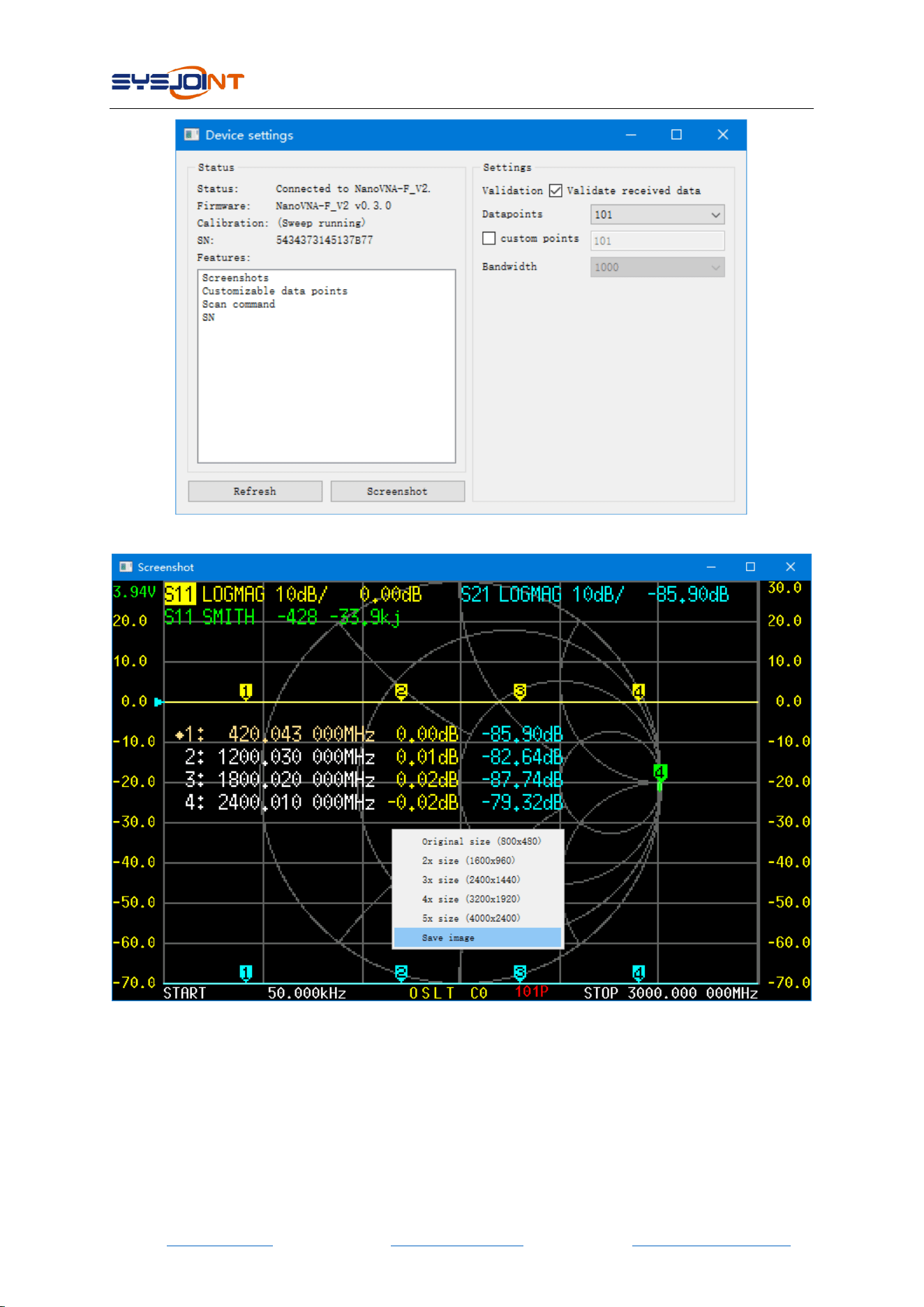
It is possible to get the device screen dump through the PC software:
(1) Click【Manage】to open ‘Device setting’ dialog box.
(2) Click【Screenshot】and wait for about 5 seconds.
(3) Move the mouse to the image area, right-click and select "Save Image" to save the
screenshot image to local disk.
NanoVNA-F V2 portable vector network analyzer user guide V2.0
©2016-2021 SYSJOINT Information Technology Co., Ltd.
- 28 -
7. Console Command
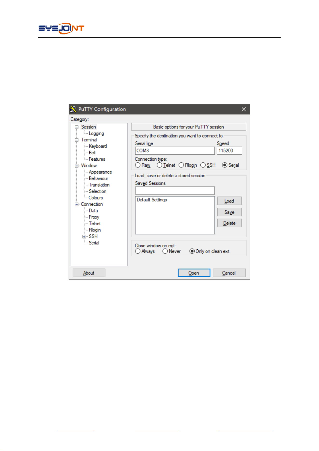
NanoVNA-F V2 supports character console commands, you can interact with the device
through serial tools (such as PuTTY).
It is also possible to design a customized PC software according to the commands.
The serial port baud rate of NanoVNA-F V2 is adaptive, usually we choose a baud rate of
115200, as shown in the figure below:
7.1. Command Syntax
A command line is a string of characters sent from PC to NanoVNA-F V2. A command line has a
command, a body, and a terminator. Each command line must begin with a command and must
be terminated by a carriage return. The command line is a string of printable ASCII characters
(032 - 126). Space characters (ASCII 032) and control characters other than CR (ASCII 013) and
BS (ASCII 010) in the command string are ignored. The default terminator is the ASCII <CR>
character. The command line interpretation begins upon receipt of the carriage return character.
A typical command line is as follows:
Command {parameter 1} [parameter 2] [parameter 3] [parameter 4|parameter n]
Where { } represents the parameters must be passed in, [ ] stands for optional parameters.
NanoVNA-F V2 portable vector network analyzer user guide V2.0
©2016-2021 SYSJOINT Information Technology Co., Ltd.
- 29 -
7.2. Command Description
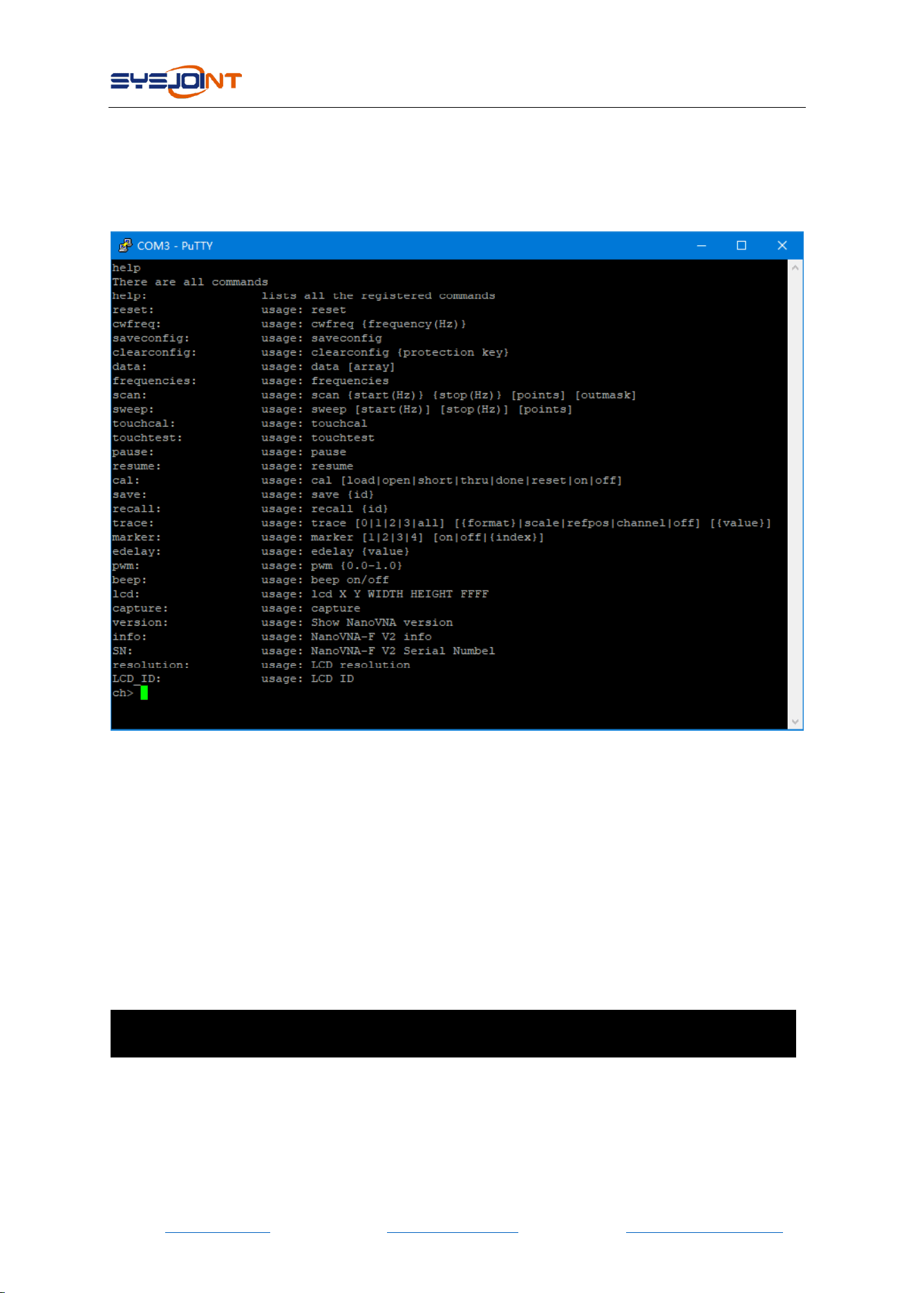
7.2.1 help
Use this command to list all the registered commands:
7.2.2 reset
This command is used to reset the device. No parameters are required for this command. After
using this command, the device will restart, and the USB will disconnect, so you need to restart
the serial tool and reconnect.
7.2.3 cwfreq
This command is used to set the CW pulse frequency. The command contains one parameter
(frequency in Hz). For example, set the CW pulse frequency of 450MHz:
cwfreq 450000000
7.2.4 saveconfig
This command is used to save language setting and touch calibration. No parameters are
required for this command.

NanoVNA-F V2 portable vector network analyzer user guide V2.0
©2016-2021 SYSJOINT Information Technology Co., Ltd.
- 30 -
7.2.5 clearconfig
This command is used to restore the device to factory settings. This command requires a fixed
parameter: ‘1234’
clearconfig 1234
CAUTION: Sending this command will cause all settings and calibration data get lost.
7.2.6 data
This command is used to get the measurement data. The optional parameter [array] is used to
specify the channel: 0 for s11, 1 for s21. When there is no parameter, executing this command
will print s11 data by default.
7.2.7 frequencies
This command is used to get the frequency list of the sweep. No parameters are required for
this command.
7.2.8 scan
This command is used to set start frequency, stop frequency, sweep points, and the printout
format of the measurement results.
scan {start(Hz)} {stop(Hz)} [points] [outmask]
Parameter descriptions:
start
Star frequency
stop
Stop frequency
points
Sweep points, range from 11 to 201
outmask
0: No printout;
1: Print the frequency value of each sweep point;
2: Print s11 data of each sweep point;
3: Print frequency value and s11 data of each sweep point;
4: Print s21 data of each sweep point;
5: Print frequency value and s21 data of each sweep point;
6: Print s11 data and s21 data of each sweep point;
7: Print frequency value, s11 data and s21 data of each sweep.
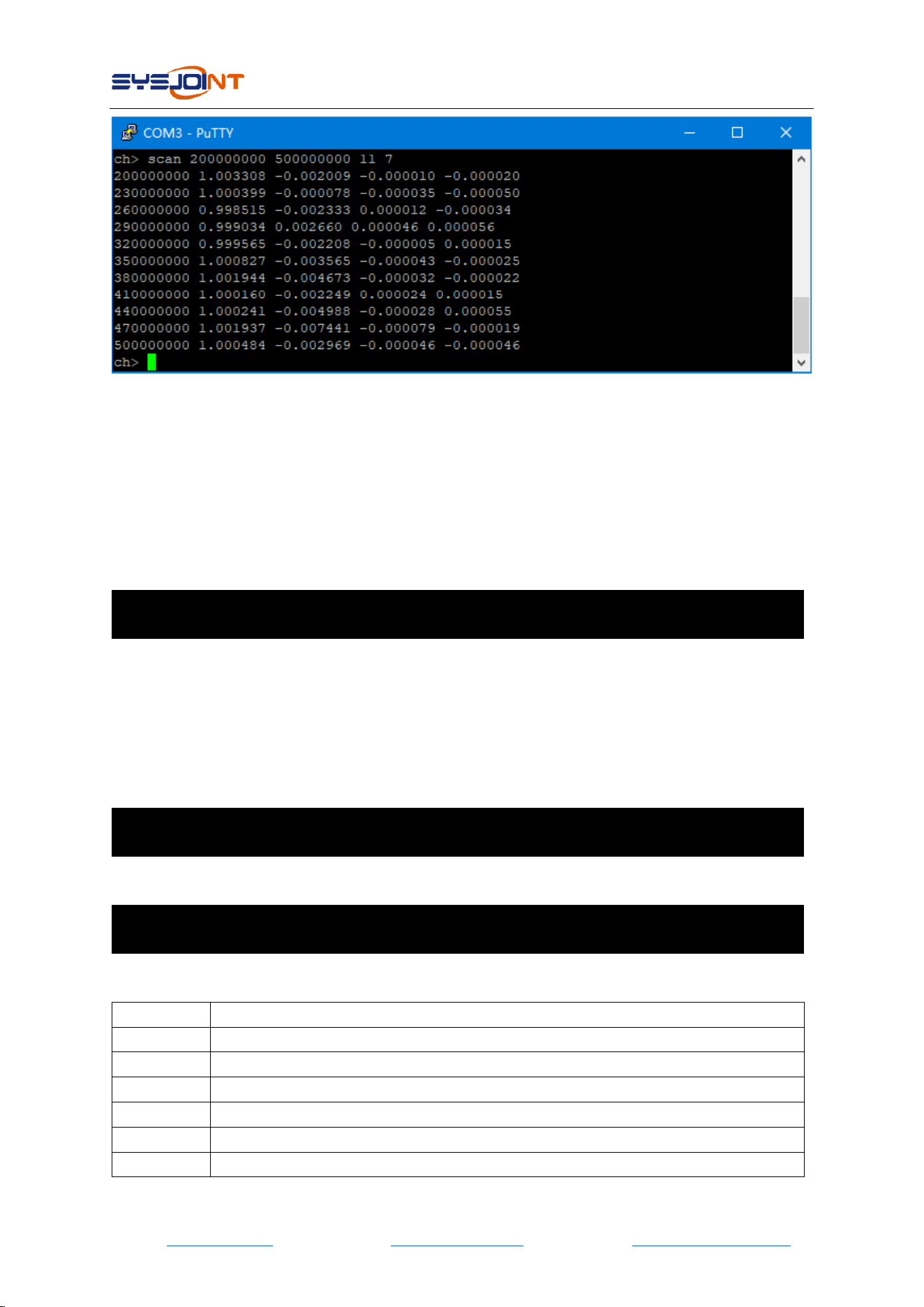
Example: Set frequency range 200MHz - 500MHz, 11 points, print frequency value, s11 data and
s21 data:
NanoVNA-F V2 portable vector network analyzer user guide V2.0
©2016-2021 SYSJOINT Information Technology Co., Ltd.
- 31 -
As shown in the figure above, the first column is the frequency value of each sweep point, the
second column is the real part of s11 data, the third column is the imaginary part of s11 data, the
fourth column is the real part of s21 data, and the fifth column is the imaginary part of s21 data.
7.2.9 sweep
This command is used to set sweep mode, frequency, and sweep points.
There are two ways to use sweep command.
Usage1:
sweep [start(Hz)] [stop(Hz)] [points]
If there is no parameter, executing this command will print the current sweep range and points;
For the case of one integer parameter, the parameter is interpretated as start frequency;
For the case of two integer parameters, parameters are interpretated as start and stop
frequencies.
For the case of three integer parameters, the first two parameters are interpretated as start and
stop frequencies, the third parameter is interpretated as sweep points.
Example: set start frequency to 200MHz, stop frequency to 500MHz, and sweep points to 78.
sweep 200000000 500000000 78
Usage2:
sweep [start|stop|span|center|cw|points] [value]
Parameter descriptions:
start
Set start frequency
stop
Set stop frequency
span
Set span frequency
center
Set center frequency
cw
Set CW frequency
points
Set sweep points, range from 11 to 201
value
Frequency value in Hz or sweep points

NanoVNA-F V2 portable vector network analyzer user guide V2.0
©2016-2021 SYSJOINT Information Technology Co., Ltd.
- 32 -
Example: set start frequency to 200MHz.
sweep start 200000000
7.2.10 touchcal
This command is used to calibrate the touchscreen. When executing this command, a cross will
appear in the upper left corner of the screen, tap the center of the cross (recommended to
operate with a stylus), then a second cross will appear in the lower right corner of the screen, tap
the center of the second cross to complete the touch screen calibration.
Tap the center of the first cross
Tap the center of the second cross
Note: After completing the calibration of the touch screen, you MUST execute saveconfig
command to save the calibration data.
7.2.11 touchtest
This command is used to test whether the touch pad is correctly calibrated. After sending this
command, user can draw on the screen (recommended to operation with a stylus) to check
whether the touch operation is accurate.
7.2.12 pause
Execute this command to pause sweep.
7.2.13 resume
Execute this command to resume sweep.
7.2.14 cal
This command is used for calibration.
Usage:
cal [load|open|short|thru|done|reset|on|off]

NanoVNA-F V2 portable vector network analyzer user guide V2.0
©2016-2021 SYSJOINT Information Technology Co., Ltd.
- 33 -
Parameter descriptions:
no parameter
Get the calibration status of the device
load
Perform load calibration
open
Perform open calibration
short
Perform short calibration
thru
Perform thru calibration
done
Complete calibration
reset
Clear calibration data
on
Apply calibration
off
Disapply calibration
NOTE: Please send command ‘cal reset’ before performing calibration. When calibrating, please
firstly connect the calibration kit to the SMA port of the device, wait for 2-3 sweeps, and then
send the corresponding cal command.
7.2.15 save
This command is used to save calibration data, and it can also save the trace settings and the
marker table position. The parameter ‘id’ indicates the storage slot number of the calibration
data, the value range is 0-6.
save {id}
7.2.16 recall
This command is used to recall the calibration data stored in the device, and it can also recall the
trace settings and the marker table position. The parameter ‘id’ indicates to the storage slot
number of the calibration data, the value range is 0-6.
recall {id}
7.2.17 trace
This command is used to view or set the attributes of trace.
Usage:
trace [0|1|2|3|all] [{format}|scale|refpos|channel|off] [value]
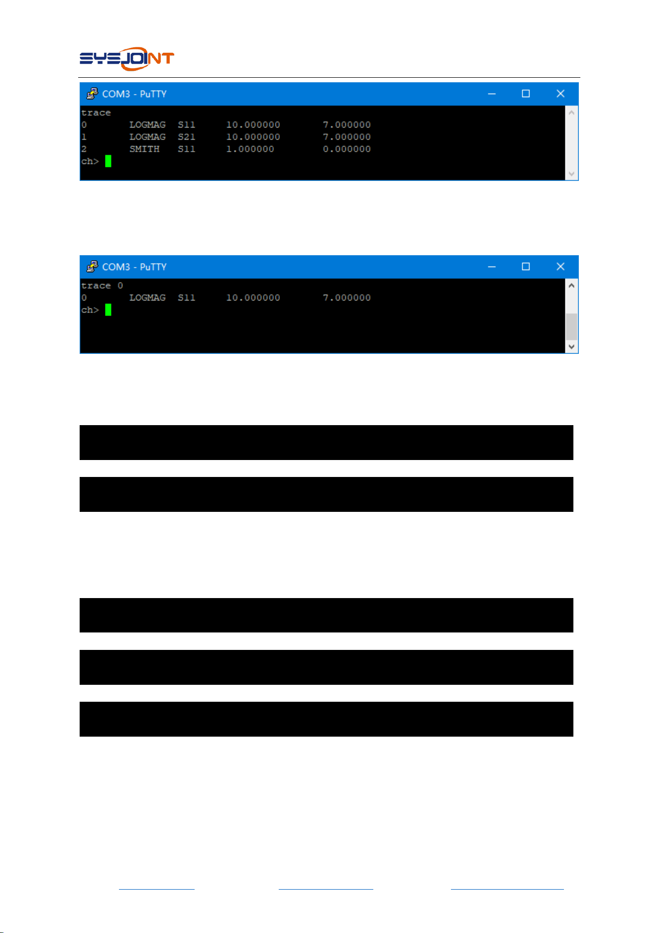
If there is no parameter, sending this command will get the attributes (format, channel, scale,
and reference position) of all the opened traces.
Example: get the attributes of all the opened traces:
NanoVNA-F V2 portable vector network analyzer user guide V2.0
©2016-2021 SYSJOINT Information Technology Co., Ltd.
- 34 -
For the case of one parameter, the parameter indicates to the trace number. Sending this
command will get the attributes of the corresponding trace.
Example: get the attributes of trace 0:
For the case of two parameters, the first parameter indicates to the trace number, the second
parameter indicates to the trace format (logmag, phase, smith, linear, delay, swr).
Example: set trace 0 format of swr:
trace 0 swr
Example: turn off all traces:
trace all off
For the case of three parameters, the first parameter indicates to the trace number, the second
parameter can be ‘scale’, ‘refpos’ or ‘channel’, the third parameter is used to specify the value of
scale, reference position or channel.
Example: set trace 0 scale of 15
trace 0 scale 15
Example: set trace 1 reference position of 5
trace 1 refpos 5
Example: set trace 0 channel to S21 (0 for S11 and 1 for S21)
trace 0 channel 1
7.2.18 marker
This command is used to view or set the attributes of markers.
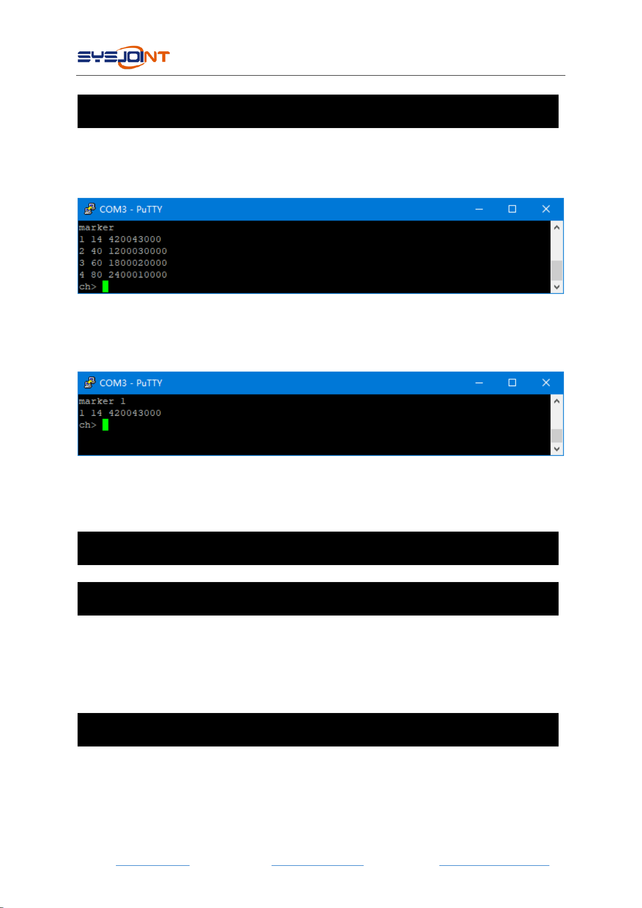
NanoVNA-F V2 portable vector network analyzer user guide V2.0
©2016-2021 SYSJOINT Information Technology Co., Ltd.
- 35 -
Usage:
marker [1|2|3|4] [on|off|{index}|
If there is no parameter, sending this command will get the attributes (index, frequency) of all
the opened markers.
Example: get the attributes of all the opened markers:
For the case of one parameter, the parameter indicates to the marker number, sending this
command will get the attributes (index, frequency) of the corresponding markers.
Example: get the attributes of marker 1:
For the case of two parameters, the first parameter indicates to the marker number, the second
parameter can be ‘on’, ‘off’ or index value, which is used to turn on/off or move the marker to
the specified position.
Example: turn off marker 1:
marker 1 off
Example: move marker 1 to 56th sweep point.
marker 1 56
7.2.19 edelay
This command is used to set delay time to compensate the electrical delay introduced by
connectors and cables.
Usage:
edelay [value]
If there is no parameter, sending this command will get the current edelay value.
For the case of one parameter, the parameter indicates to the delay time in ns, and the value
can be either positive or negative.

NanoVNA-F V2 portable vector network analyzer user guide V2.0
©2016-2021 SYSJOINT Information Technology Co., Ltd.
- 36 -
Example: set edelay time -100ps
edelay -0.1
7.2.20 pwm
This command is used to adjust the screen brightness.
Useage:
pwm {0.0-1.0}
Example: set 85% brightness:
pwm 0.85
7.2.21 beep
This command is used to test the buzzer.
Usage:
beep on/off
7.2.22 lcd
This command is used to implement rectangular filling on the LCD screen.
Usage:
lcd {X} {Y} {WIDTH} {HEIGHT} {FFFF}
Parameter descriptions:
X
X-axis start position
Y
Y-axis start position
WIDTH
The width of the rectangle
HEIGHT
The height of the rectangle
FFFF
16 bits hexadecimal RGB value
Example: Fill a 50*50 red square at the starting coordinates (100, 100)
lcd 100 100 50 50 F800
7.2.23 capture
This command is used to get the screenshot. No parameters are required for this command.
Data is transmitted in hexadecimal little-endian mode. One pixel is composed of 16 bits and
divided into two bytes. The screenshot data is sent in the format of line scan. Since the screen
resolution is 800*480, the screenshot image is transmitted in 480 times, 800 pixels per transfer.

NanoVNA-F V2 portable vector network analyzer user guide V2.0
©2016-2021 SYSJOINT Information Technology Co., Ltd.
- 37 -
7.2.24 version
This command is used to check the firmware version. No parameters are required for this
command.
7.2.25 info
This command is used to get the device information. No parameters are required for this
command.
7.2.26 SN
This command is used to get the unique 16-bit serial number of the device. No parameters are
required for this command.
7.2.27 resolution
This command is used to get the LCD resolution. No parameters are required for this command.
7.2.28 LCD_ID
This command is used to get the LCD ID. No parameters are required for this command.
8. Firmware Upgrade
The firmware of NanoVNA-F V2 can be upgraded through virtual U-disk without a programmer
(such as J-LINK). The upgrade can be done with the USB Type-C cable.
Connect NanoVNA-F V2 to PC with the USB Type-C cable, push and hold the middle push
button, then power on NanoVNA-F V2. The device will be recognized as a U disk drive, and the
following prompt information will appear on the device screen.
Firmware upgrade:
1. Connect the device to PC with Type-C cable;
2. The device will be recognized as a U-Disk;
3. Copy ‘update.bin’ into the U-Disk;
4. Power off and on;
According to the prompt information, the file ‘update.bin’ is required, which can be downloaded
from our official website: www.sysjoint.com/nanovna-f_v2.html
Download the firmware file and unzip it to get ‘update.bin’.
Copy ‘update.bin’ into the U-Disk, it may take 10-15 seconds.
Power off and on the device, the firmware upgrade will complete automatically.
When the firmware upgrade complete, the device will restart automatically, you can check the
NanoVNA-F V2 portable vector network analyzer user guide V2.0
©2016-2021 SYSJOINT Information Technology Co., Ltd.
- 38 -
firmware version when the device startup.
CAUTION: If the current firmware version of your NanoVNA-F V2 device is lower than v0.2.0,
please upgrade to v0.2.0 first, and then it can be upgraded to higher version of the firmware.
When upgrade to v0.2.0, you must copy ’update.bin’ and ’update.all’ TOGETHER into the virtual
u-disk.
Firmware v0.2.0 download: http://www.sysjoint.com/file/NanoVNA-F_V2_App_v0.2.0.zip
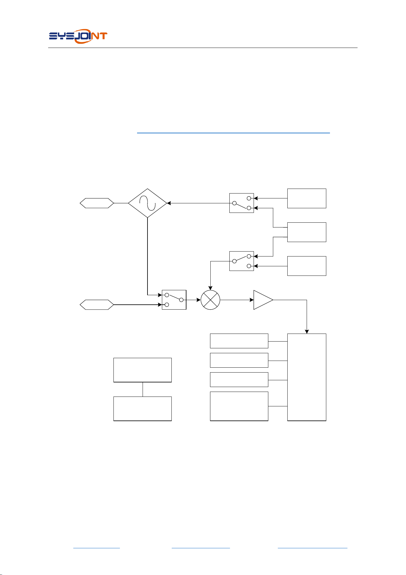
9. Hardware Architecture
SI5351
PORT1
PORT2
ADF4350
ADF4350
Baseband
Amplifier
STM32
F103VET6
IPS LCD
800x480
AD8342
Li-Po
5000mAh
16MB flash
Button x 3
USB type-c
Power
Management
Coupler
