
Owner’s Manual
IMPORTANT NOTE:
Read this manual carefully before installing
or operating your new air conditioning unit.
Make sure to save this manual for future
reference.
ROOM AIR CONDITIONER
SPLIT-TYPE
ECOWAL Series

Operation Instructions
CONTENTS
01
Get to Know Your AC
13
Manual Operation(without remote)
Care and Maintenance
16
Troubleshooting
17
19
Safety Precautions
02
Setting Angle of Air Flow
15
More features
14
02
Safety Precautions
WARNING
CAUTION
Explanation of Symbols
WARNING
This appliance is not intended for use by persons(including children) with reduced
physical, sensory or mental capabilities, or lack of experience and knowledge, unless
they have been given supervision or instruction concerning use of the appliance by
a person responsible for their safety. Children should be supervised to ensure that
they do not play with the appliance.
This symbol indicates the possibility of personnel injury or loss of
life.
This symbol indicates the possibility of property damage or serious
consequences.
If an abnormal situation arises (like a burning smell), immediately turn o the
unit and disconnect the power. Call your dealer for instructions to avoid electric
shock, fire or injury.
Do not insert fingers, rods or other objects into the air inlet or outlet. This may
cause injury, since the fan may be rotating at high speeds.
Do not use flammable sprays such as hair spray, lacquer or paint near the unit.
This may cause fire or combustion.
Do not operate the air conditioner in places near or around combustible gases.
Emitted gas may collect around the unit and cause explosion.
Do not operate your air conditioner in a wet room such as a bathroom or laundry
room. Too much exposure to water can cause electrical components to short
circuit.
Do not expose your body directly to cool air for a prolonged period of time.
If the air conditioner is used together with burners or other heating devices,
thoroughly ventilate the room to avoid oxygen deficiency.
In certain functional environments, such as kitchens, server rooms, etc., the use
of specially designed air-conditioning units is highly recommended.
Do not allow children to play with the air conditioner. Children must be
supervised around the unit at all times.
●
●
●
●
●
●
●
●
●
●
WARNING FOR PRODUCT USE
Turn o the air condtioner and disconnect the power before performing any
cleaning, installation or repairing. Failure to do so can cause electric shock.
It is really important that you read Safety Precautions Before Operation and
Installation. Incorrect installation due to ignoring instructions can cause serious
damage or injury. The seriousness of potential damage or injuries is classified as
either a WARNING or CAUTION.
03
ELECTRICAL WARNINGS
Only use the specified wire. If the wire is damaged, it must be replaced by the
manufacturer, its service agent or similarly qualified persons in order to avoid a
hazard.
The product must be properly grounded at the time of installation, or electric
shock may occur.
For all electrical work, follow all local and national wiring standards, regulations,
and the Installation Manual. Connect cables tightly, and clamp them securely to
prevent external forces from damaging the terminal. Improper electrical
connections can overheat and cause fire, and may also cause shock. All electrical
connections must be made according to the Electrical Connection Diagram
located on the panels of the indoor and outdoor units.
All wiring must be properly arranged to ensure that the control board cover can
close properly. If the control board cover is not closed properly, it can lead to
corrosion and cause the connection points on the terminal to heat up, catch fire,
or cause electric shock.
Disconnection must be incorporated in the fixed wiring in accordance with the
wiring rules.
Do not share the electrical outlet with other appliances. Improper or insucient
power supply can cause fire or electric shock.
If connecting power to fixed wiring, an all-pole disconnection device which has
at least 3mm clearances in all poles, and have a leakage current that may exceed
10mA, the residual current device (RCD) having a rated residual operating current
not exceeding 30mA, and disconnection must be incorporated in the fixed wiring
in accordance with the wiring rules.
●
●
●
●
●
●
●
Do not clean the air conditioner with combustible cleaning agents. Combustible
cleaning agents can cause fire or deformation.
Turn o the device and disconnect the power before cleaning. Failure to do so
can cause electric shock.
Do not clean the air conditioner with excessive amounts of water.
●
●
●
CLEANING AND MAINTENANCE WARNINGS
Turn o the air conditioner and disconnect the power if you are not going to use
it for a long time.
Turn o and unplug the unit during storms.
Make sure that water condensation can drain unhindered from the unit.
Do not operate the air conditioner with wet hands. This may cause electric shock.
Do not use device for any other purpose than its intended use.
Do not climb onto or place objects on top of the outdoor unit.
Do not allow the air conditioner to operate for long periods of time with doors or
windows open, or if the humidity is very high.
●
●
●
●
●
●
●
CAUTION
WARNING FOR USING FLAMMABLE REFRIGERANTS
●
●
Do not use means to accelerate the defrosting process or to clean, other than
those recommended by the manufacturer.
The appliance shall be stored in a room without continuously operating ignition
sources (for example: open flames, an operating gas appliance or an operating
electric heater).
04
For R454B refrigerant charge amount and minimum room area:
●
●
●
Do not pierce or burn.
Be aware that refrigerants may not contain an odour.
LEAK DETECTION SYSTEM installed. Unit must be powered except for service.
When the refrigerant sensor detects refrigerant leakage, the indoor unit will
display a error code and emit a buzzing sound, the compressor of outdoor unit
will immediately stop, and the indoor fan will start running. The service life of the
refrigerant sensor is 15 years. When the refrigerant sensor malfunctions, the
indoor unit will display the error code “FHCC”. The refrigerant sensor can not be
repaired and can only be replaced by the manufacture. It shall only be replaced
with the sensor specified by the manufacture.(Applicable to the units with
refrigerant sensors only)
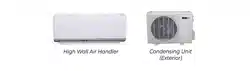
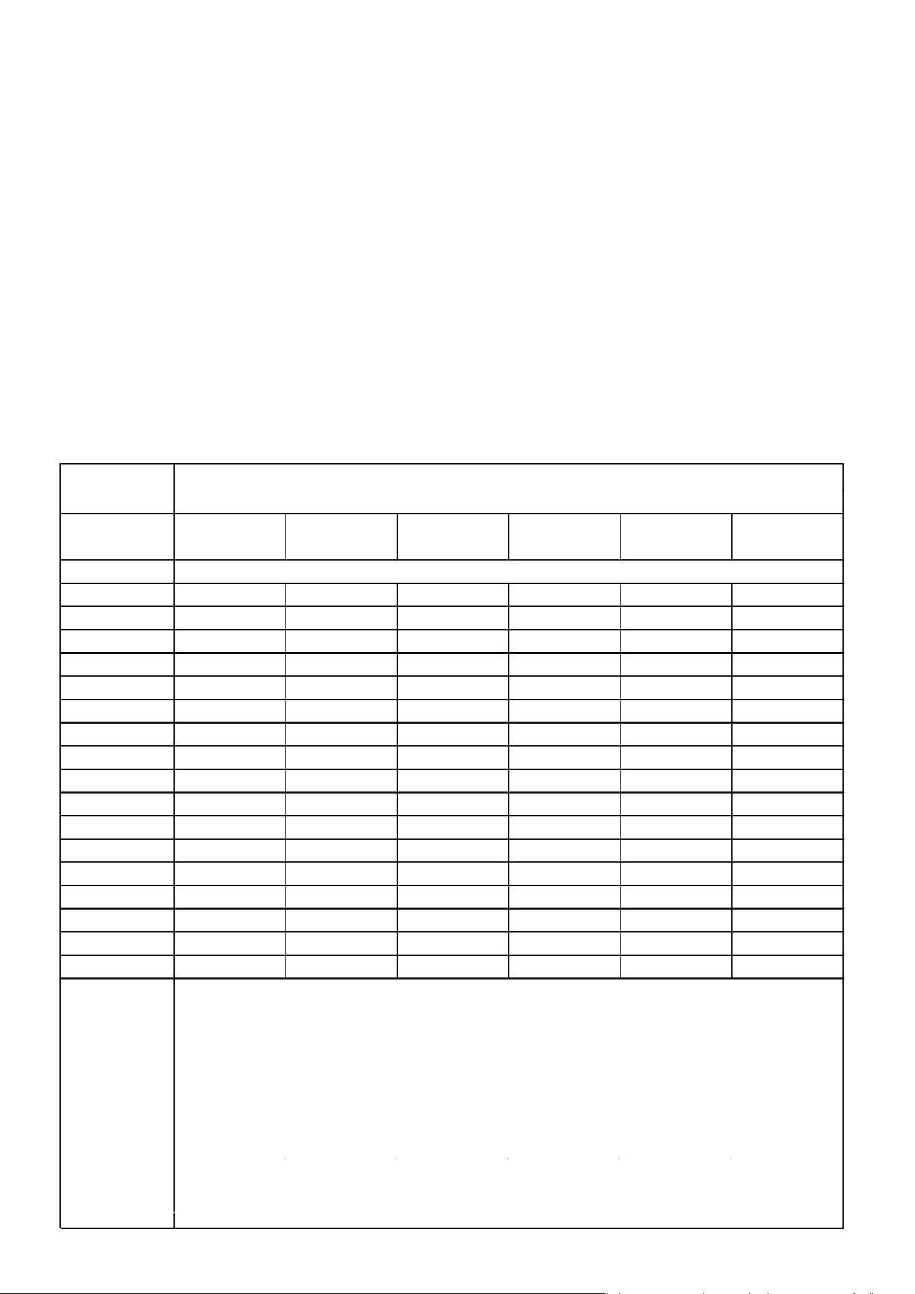
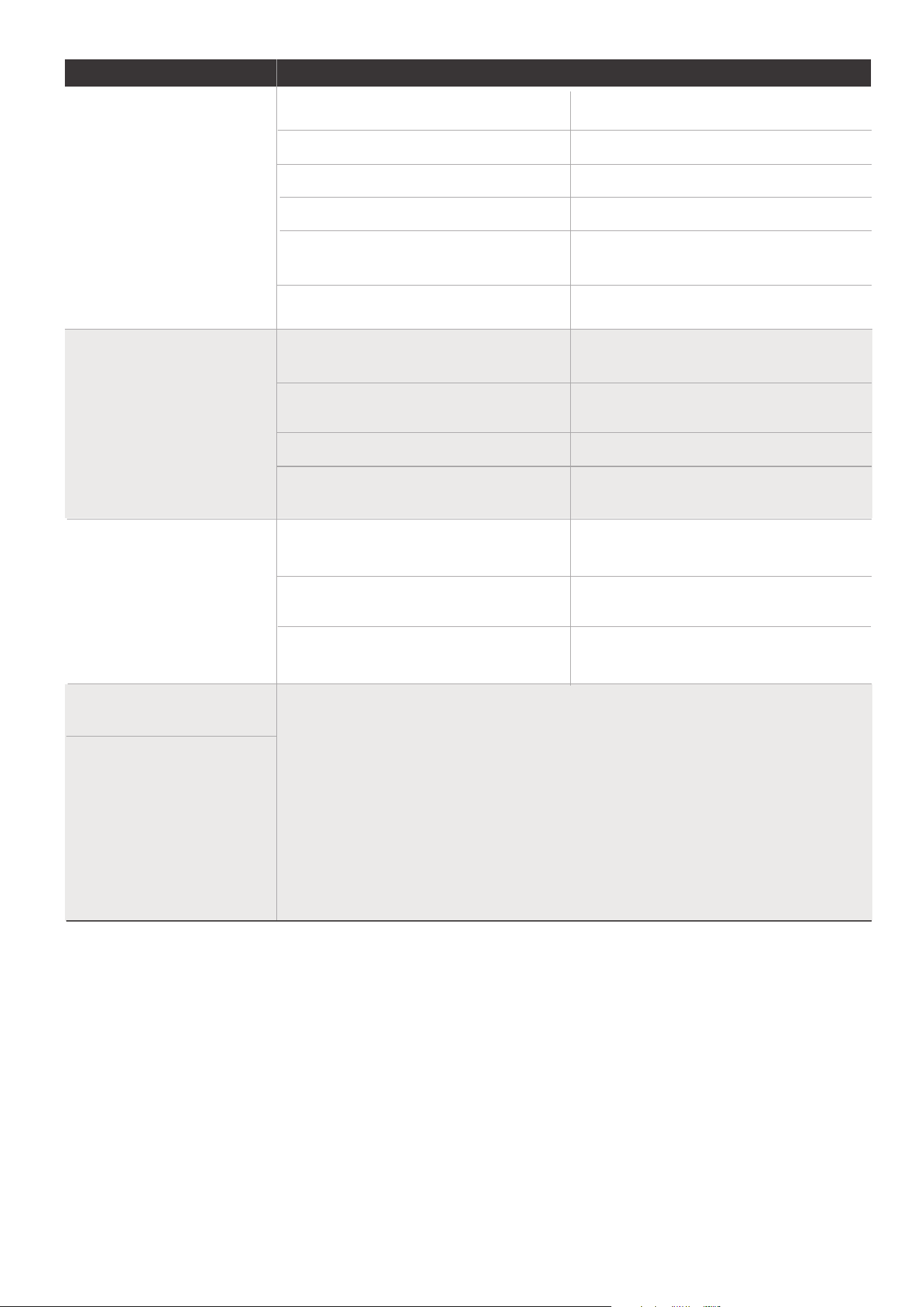
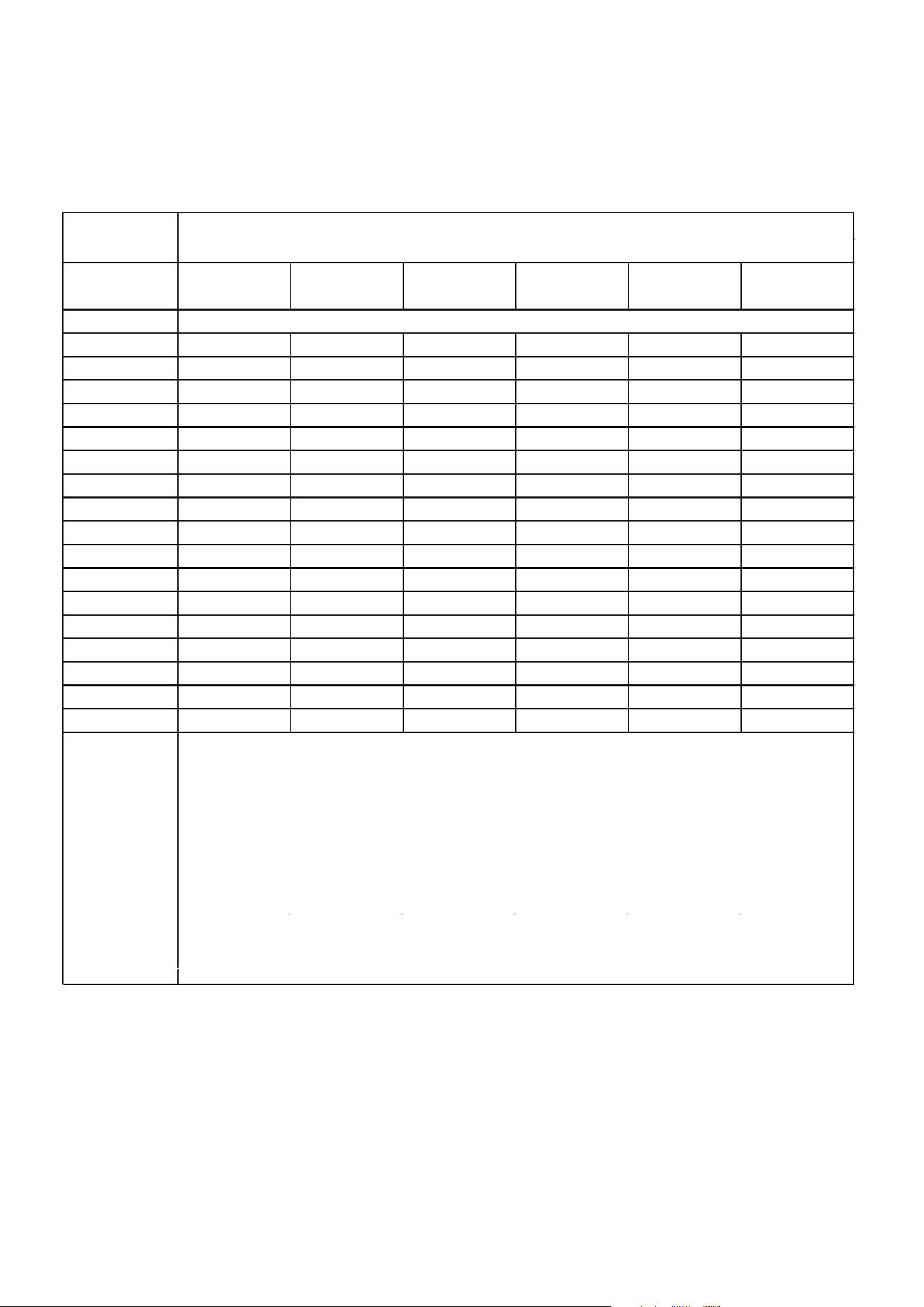
The machine you purchased may be one of the types in the table below. The indoor
and outdoor units are designed to be used together. Please check the machine you
purchased.The indoor unit should be installed at least 6.0ft /1.8m above from the
floor, the height of the room cannot be less than 7.3ft /2.2m, and the minimum
room area of operating or storage should be as specified in the following table.
A
min
[ft2/m2]
m
c or
mREL
[oz/kg]
6.0~7.3/
1.8~2.2
7.6/2.3 7.9/2.4 8.6/2.6 9.2/2.8 9.9/3.0
<=62.6/1.776
63.4/1.8 60/5.53 57/5.29 55/5.07 51/4.68 47/4.35 44/4.06
70.5/2.0 67/6.15 64/5.88 61/5.64 56/5.2 52/4.83 49/4.51
77.5/2.2 73/6.76 70/6.47 67/6.2 62/5.72 58/5.31 54/4.96
84.6/2.4 80/7.38 76/7.06 73/6.76 68/6.24 63/5.8 59/5.41
91.7/2.6 86/7.99 83/7.64 79/7.32 73/6.76 68/6.28 64/5.86
98.7/2.8 93/8.6 89/8.23 85/7.89 79/7.28 73/6.76 68/6.31
105.8/3.0 100/9.22 95/8.82 91/8.45 84/7.8 78/7.24 73/6.76
112.8/3.2 106/9.83 102/9.41 97/9.01 90/8.32 84/7.73 78/7.21
119.9/3.4 113/10.45 108/9.99 104/9.58 96/8.84 89/8.21 83/7.66
126.9/3.6 120/11.06 114/10.58
110/10.14 101/9.36 94/8.69 88/8.11
134/3.8 126/11.68 121/11.17 116/10.7 107/9.88 99/9.17 93/8.56
141.1/4.0 133/12.29 127/11.76 122/11.27 112/10.4 104/9.66 97/9.01
148.1/4.2 139/12.9 133/12.34 128/11.83 118/10.92 110/10.14 102/9.46
155.1/4.4 146/13.52 140/12.93 134/12.39 124/11.44 115/10.62 107/9.91
162.2/4.6 153/14.13 146/13.52 140/12.96 129/11.96 120/11.11 112/10.37
169.2/4.8 159/14.75 152/14.11 146/13.52 135/12.48 125/11.59 117/10.82
176.3/5.0 166/15.36 159/14.69 152/14.08 140/13 130/12.07 122/11.27
Area
formula
h
inst
[ft/m]
12/1.10
A
min
is the required minimum room area in ft /m
m
c
is the actual refrigerant charge in the system in oz/kg
m
REL is the refrigerant releaseable charge in oz/kg
(Applicable to the
units with refrigerant sensors only)
h
inst
is the height of the bottom of the appliance relative to the floor of
the room after installation.
WARNING: The minimum room area or minimum room area of
conditioned space is based on releasable charge and total
system refrigerant charge.
2 2
05
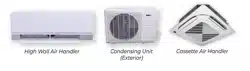
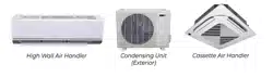
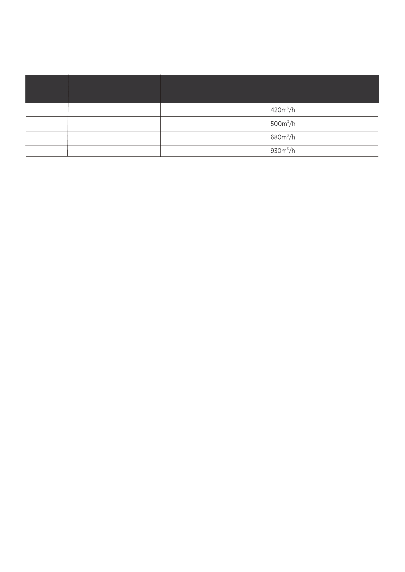
Indoor unit Outdoor unit
09K
12K
ECOWAL09DA
ECOSZ109DA
18K
Model
295CFM
245CFM
400CFM
ECOSZ112DA
ECOWAL12DA
ECOWAL18DA ECOSZ118DA
24K
545CFM
ECOWAL24DA ECOSZ124DA
Indoor nominal air volume
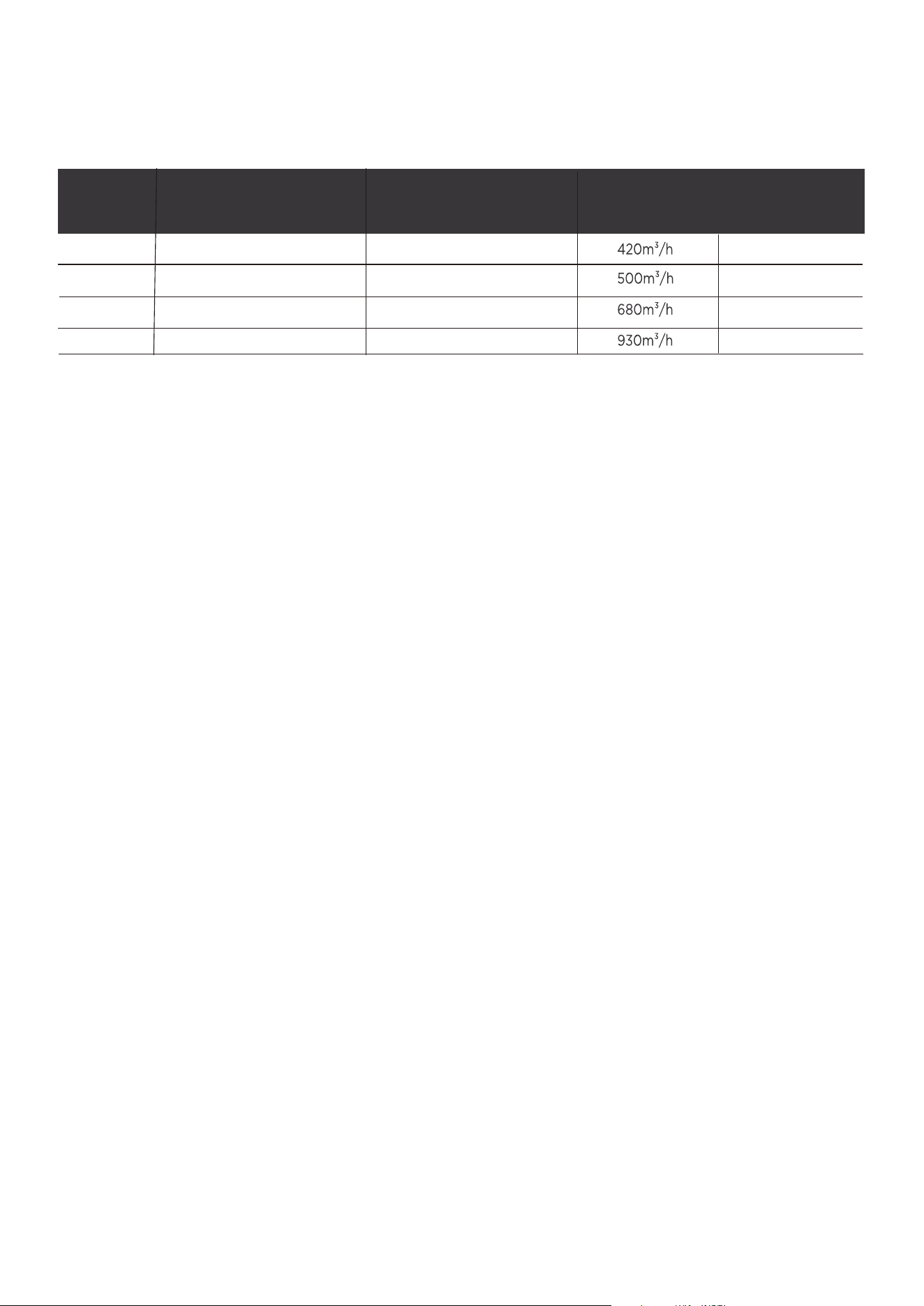
For the units with refrigerant sensors, when the unit detects a refrigerant leak, the
minimum airflow of the indoor unit is as follows:
Entry Tier Series

Indoor unit Outdoor unit
09K
12K
18K
Model
24K
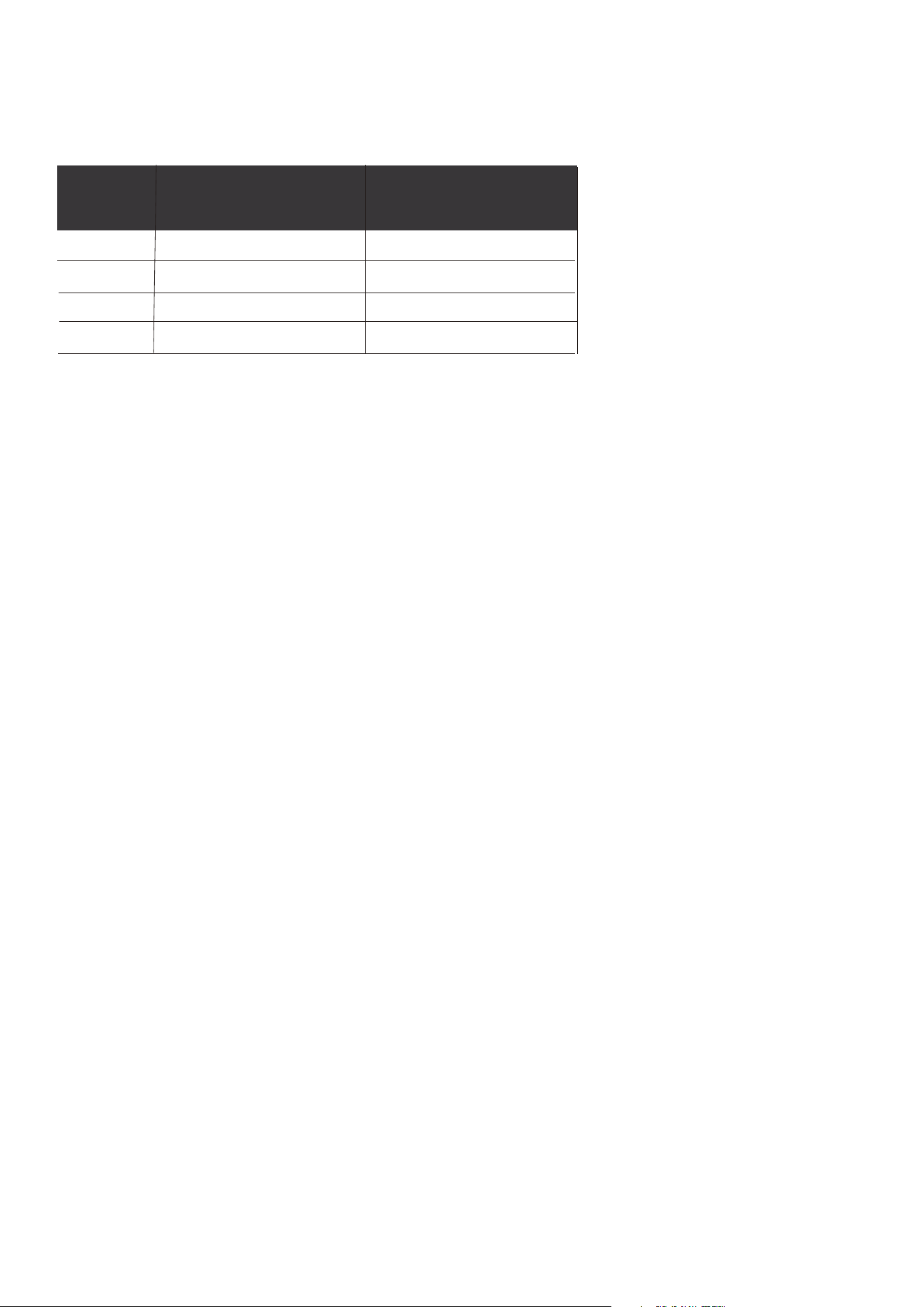
The information in the following table is only applicable to models without
refrigerant sensors:
Entry Tier Series
06
ECOWAL09DA
ECOWAL12DA
ECOWAL18DA
ECOWAL24DA
ECOSZ109DA
ECOSZ112DA
ECOSZ118DA
ECOSZ124DA

07
1. Installation(where refrigerant pipes are allowed)
- Any person who is involved with working on or breaking into a refrigerant
circuit should hold a current valid certificate from an industry-accredited
assessment authority, which authorises their competence to handle refrigerants
safely in accordance with an industry recognised assessment specification.
- Maintenance and repair requiring the assistance of other skilled personnel shall
be carried out under the supervision of the person competent in the use of
flammable refrigerants.
- That the installation of pipe-work shall be kept to a minimum.
- That pipe-work shall be protected from physical damage.
- Where refrigerant pipes shall be compliance with national gas regulations.
- That mechanical connections shall be accessible for maintenance purposes.
- Be more careful that foreign matter(oil, water,etc) does not enter the piping.
Also, when storing the piping, securely seal the opening by pinching, taping, etc.
- Appliance shall be stored in a well ventilated area where the room size
corresponds to the room area as specifiec for operation.
2. When a FLAMMABLE REFRIGERANT is used, the requirements for installation
space of appliance and /or ventilation requirements are determined according to
- the mass charge amount(M) used in the appliance,
- the installation location,
- the type of ventilation of the location or of the appliance.
- piping material, pipe routing, and installation shall include protection from
physical damage in operation and service, and be in compliance with national
and local codes and standards, such as ASHRAE 15, IAPMO Uniform Mechanical
Code, ICC International Mechanical Code, or CSA B52. All field joints shall be
accessible for inspection prior to being covered or enclosed.
- that protection devices, piping, and fittings shall be protected as far as
possible against adverse environmental eects, for example, the danger of water
collecting and freezing in relief pipes or the accumulation of dirt and debris;
- that piping in refrigeration systems shall be so designed and installed to
minimize the likelihood of hydraulic shock damaging the system;
- that steel pipes and components shall be protected against corrosion with a
rustproof coating before applying any insulation;
- that precautions shall be taken to avoid excessive vibration or pulsation;
- the minimum floor area of the room shall be mentioned in the form of a table
or a single figure without reference to a formula;
- after completion of field piping for split systems, the field pipework shall be
pressure tested with an inert gas and then vacuum tested prior to refrigerant
charging, according to the following requirements:
- Joints shall be tested with detection equipment with a capability of 5 g/year of
refrigerant or better, with the equipment in standstill and under operation or
under a pressure of at least these standstill or operation conditions after
installation. Detachable joints shall NOT be used in the indoor side of the unit
(brazed, welded joint could be used).
- In cases that require mechanical ventilation, ventilation openings shall be kept
clear of obstruction.
a. The minimum test pressure for the low side of the system shall be the low side
design pressure and the minimum test pressure for the high side of the system
shall be the high side design pressure, unless the high side of the system can
not be isolated from the low side of the system in which case the entire system
shall be pressure tested to the low side design pressure.
b. The test pressure after removal of pressure source shall be maintained for at
least 1 h with no decrease of pressure indicated by the test gauge, with test
gauge resolution not exceeding 5% of the test pressure.

08
c. During the evacuation test, after achieving a vacuum level specified in the
manual or less, the refrigeration system shall be isolated from the vacuum pump
and the pressure shall not rise above 1500 microns within 10 min. The vacuum
pressure level shall be specified in the manual, and shall be the lessor of 500
microns or the value required for compliance with national and local codes and
standards, which may vary between residential, commercial,and industrial
buildings.
-- field-made refrigerant joints indoors shall be tightness tested according to the
following requirements: The test method shall have a sensitivity of 5 grams per
year of refrigerant or better under a pressure of at least 0,25 times the
maximum allowable pressure. No leak shall be detected.
-- Any servicing shall be performed only as recommended by the manufacturer.
3 . Qualification of workers
Any maintenance, service and repair operations must be required qualification
of the working personnel. Every working procedure that aects safety means
shall only be carried out by competent persons that joined the training and
achieved competence should be documented by a certificate. The training of
these procedures is carried out by national training organizations or
manufacturers that are accredited to teach the relevant national competency
standards that may be set in legislation. All training shall follow the ANNEX HH
requirements of UL 60335-2-40 4th Edition.
Examples for such working procedures are:
• breaking into the refrigerating circuit;
• opening of sealed components;
• opening of ventilated enclosures.
Information Servicing
1. Checks to the area
3. General work area
4. Checking for presence of refrigerant
5. Presence of fire extinguisher
If any hot work is to be conducted on the refrigeration equipment or any associated
parts, appropriate fire extinguishing equipment shall be available to hand. Have a
dry power or CO
2 fire extinguisher adjacent to the charging area.
2. Work procedure
All maintenance sta and others working in the local area shall be instructed on the
nature of work being carried out. work in confined sapces shall be avoided.
Prior to beginning work on systems containing flammable refrigerants, safety checks
are necessary to ensure that the risk of ignition is minimised. For repair to the
refrigerating system, the following precautions shall be complied with prior to
conducting work on the system.
Works shall be undertaken under a controlled procedure so as to minimise the risk
of a flammable gas or vapour being present while the work is being performed.
The area shall be checked with an appropriate refrigerant detector prior to and
during work, to ensure the technician is aware of potentially flammable atmospheres.
Ensure that the leak detection equipment being used is suitable for use with
flammable refrigerants, i.e. no sparking, adequately sealed or intrinsically safe.

09
6. No ignition sources
No person carrying out work in relation to a REFRIGERATING SYSTEM which
involves exposing any pipe work shall use any sources of ignition in such a manner
that it may lead to the risk of fire or explosion. All possible ignition sources, including
cigarette smoking, should be kept suciently far away from the site of installation,
repairing, removing and disposal, during which refrigerant can possibly be released
to the surrounding space. Prior to work taking place, the area around the equipment
is to be surveyed to make sure that there are no flammable hazards or ignition risks.
“No Smoking” signs shall be displayed.
7. Ventilated area
Ensure that the area is in the open or that it it adequately ventilated before breaking
into the system or conducting any hot work. A degree of ventilation shall continue
during the period that the work is carried out. The ventilation should safely disperse
any released refrigerant and preferably expel it externally into the atmosphere.
8. Checks to the refrigeration equipment
Where electrical components are being changed, they shall be fit for the purpose
and to the correct specification. At all times the manufacturer’s maintenance and
service guidelines shall be followed. If in doubt consult the manufacturer’s technical
department for assistance. The following checks shall be applied to installations
using FLAMMABLE REFRIGERANTS:
the actual refrigerant charge is in accordance with the room size within which
the refrigerant containing parts are installed;
the ventilation machinery and outlets are operating adequately and are not
obstructed;
if an indirect refrigerating circuit is being used, the secondary circuits shall be
checked for the presence of refrigerant;
marking to the equipment continues to be visible and legible, marking and signs
that are illegible shall be corrected;
9. Checks to electrical devices
Repair and maintenance to electrical components shall include initial safety checks
and component inspection procedures. If a fault exists that could compromise
safety, then no electrical supply shall be connected to the circuit until it is
satisfactorily dealt with. If the fault cannot be corrected immediately but it is
necessary to continue operation, and adequate temporary solution shall be used.
This shall be reported to the owner of the equipment so all parties are advised.
Initial safety checks shall include:
that capacitors are discharged: this shall be done in a safe manner to avoid
possibility of sparking
that there no live electrical components and wiring are exposed while charging,
recovering or purging the system;
that there is continuity of earth bonding.
10. Sealed electrical components shall be replaced.
11. Intrinsically safe components must be replaced.
refrigeration pipe or components are installed in a position where they are
unlikely to be exposed to any substance which may corrode refrigerant
containing components, unless the components are constructed of materials
which are inherently resistant to being corroded or are suitably protected against
being so corroded.

10
12. Cabling
Check that cabling will not be subject to wear, corrosion, excessive pressure,
vibration, sharp edges or any other adverse environmental eects. The check shall
also take into account the eects of aging or continual vibration from sources such
as compressors or fans.
13. Detection of flammable refrigerants
Under no circumstances shall potential sources of ignition be used in the searching
for or detection of refrigerant leaks. A halide torch(or any other detector using a
naked flame) shall not be used.
The following leak detection methods are deemed acceptable for refrigerant
systems. Electronic leak detectors may be used to detect refrigerant leaks but, in the
case of FLAMMABLE REFRIGERANTS, the sensitivity may not be adequate, or may
need re-calibration. (Detection equipment shall be calibrated in a refrigerant-free
area.) Ensure that the detector is not a potential source of ignition and is suitable for
the refrigerant used. Leak detection equipment shall be set at a percentage of the
LFL of the refrigerant and shall be calibrated to the refrigerant employed, and the
appropriate percentage of gas (25 % maximum) is confirmed.
Leak detection fluids are also suitable for use with most refrigerants but the use of
detergents containing chlorine shall be avoided as the chlorine may react with the
refrigerant and corrode the copper pipe-work.
NOTE Examples of leak detection fluids are
- bubble method,
- fluorescent method agents.
If a leak is suspected, all naked flames shall be removed/extinguished.
If a leakage of refrigerant is found which requires brazing, all of the refrigerant shall
be recovered from the system, or isolated (by means of shut o valves) in a part of
the system remote from the leak. See the following instructions of removal of
refrigerant.
14. Removal and evacuation
When breaking into the refrigerant circuit to make repairs - or for any other purpose
conventional procedures shall be used. However, for flammable refrigerants it is
important that best practice be followed, since flammability is a consideration.
The following procedure shall be adhered to:
safely remove refrigerant following local and national regulations;
evacuate;
purge the circuit with inert gas (optional for A2L);
evacuate (optional for A2L);
continuously flush or purge with inert gas when using flame to open circuit; and
open the circuit
The refrigerant charge shall be recovered into the correct recovery cylinders if
venting is not allowed by local and national codes. For appliances containing
flammable refrigerants, the system shall be purged with oxygen-free nitrogen to
render the appliance safe for flammable refrigerants. This process might need to be
repeated several times. Compressed air or oxygen shall not be used for purging
refrigerant systems.
For appliances containing flammable refrigerants, refrigerants purging shall be
achieved by breaking the vacuum in the system with oxygen-free nitrogen and
continuing to fill until the working pressure is achieved, then venting to atmosphere,
and finally pulling down to a vacuum (optional for A2L). This process shall be
repeated until no refrigerant is within thesystem (optional for A2L). When the final
oxygen-free nitrogen charge is used, the system shall be vented down to
atmospheric pressure to enable work to take place.
The outlet for the vacuum pump shall not be close to any potential ignition sources,
and ventilation shall be available.

11
15. Charging procedures
In addition to conventional charging procedures, the following requirements shall
be followed:
Works shall be undertaken with appropriate tools only (In case of uncertainty,
please consult the manufacturer of the tools for use with flammable refrigerants)
Ensure that contamination of dierent refrigerants does not occur when using
charging equipment. Hoses or lines shall be as short as possible to minimize the
amount of refrigerant contained in them.
Cylinders shall be kept upright.
Ensure that the refrigeration system is earthed prior to charging the system with
refrigerant.
Label the system when charging is complete(if not already).
Extreme care shall be taken not to overfill the refrigeration system.
Prior to recharging the system it shall be pressure tested with oxygen free
nitrogen(OFN). The system shall be leak tested on completion of charging but
prior to commissioning. A follow up leak test shall be carried out prior to leaving
the site.
16. Decommissioning
Before carrying out this procedure, it is essential that the technician is completely
familiar with the equipment and all its detail. It is recommended good practice that
all refrigerants are recovered safely. Prior to the task being carried out, an oil and
refrigerant sample shall be taken in case analysis is required prior to re-use of
recovered refrigerant. It is essential that electrical power is available before the task
is commenced.
a) Become familiar with the equipment and its operation.
b) Isolate system electrically
c) Before attempting the procedure ensure that:
mechanical handling equipment is available, if required, for handling refrigerant
cylinders;
all personal protetive equipment is available and being used correctly;
the recovery process is supervised at all times by a competent person;
recovery equipment and cylinders conform to the appropriate standards.
d) Pump down refrigerant system, if possible.
e) If a vacuum is not possible, make a manifold so that refrigerant can be removed
from various parts of the system.
f) Make sure that cylinder is situated on the scales before recovery takes place.
g)Start the recovery machine and operate in accordance with instructions.
h)Do not overfill cylinders (no more than 80% volume liquid charge)
i) Do not exceed the maximum working pressure of the cylinder, even temporarily.
j) When the cylinders have been filled correctly and the process completed, make
sure that the cylinders and the equipment are removed from site promptly and all
isolation valves on the equipment are closed o.
k) Recovered refrigerant shall not be charged into another refrigeration system
unless it has been cleaned and checked.
17. Labelling
Equipment shall be labelled stating that it has been de-commissioned and emptied
of refrigerant. The label shall be dated and signed. For appliances containing
FLAMMABLE REFRIGERANTS, ensure that there are labels on the equipment
stating the equipment contains FLAMMABLE REFRIGERANT.
18. Recovery
When removing refrigerant from a system, either for servicing or decommissioning,
it is recommended good practice that all refrigerants are removed safely.
When transferring refrigerant into cylinders, ensure that only appropriate refrigerant
recovery cylinders are employed. Ensure that the correct number of cylinders for
holding the total system charge is available. All cylinders to be used are designated
12
for the recovered refrigerant and labelled for that refrigerant (i. e. special cylinders
for the recovery of refrigerant). Cylinders shall be complete with pressure-relief
valve and associated shut-o valves in good working order. Empty recovery
cylinders are evacuated and, if possible,cooled before recovery occurs.
The recovery equipment shall be in good working order with a set of instructions
concerning the equipment that is at hand and shall be suitable for the recovery of
the flammable refrigerant. If in doubt, the manufacturer should be consulted. In
addition, a set of calibrated weighing scales shall be available and in good working
order. Hoses shall be complete with leak-free disconnect couplings and in good
condition.
The recovered refrigerant shall be processed according to local legislation in the
correct recovery cylinder, and the relevant waste transfer note arranged. Do not
mix refrigerants in recovery units and especially not in cylinders.
If compressors or compressor oils are to be removed, ensure that they have been
evacuated to an acceptable level to make certain that flammable refrigerant does
not remain within the lubricant. The compressor body shall not be heated by an
open flame or other ignition sources to accelerate this process. When oil is drained
from a system, it shall be carried out safely.
1. Transport of equipment containing flammable refrigerants
Compliance with the transport regulations.
2. Marking of equipment using signs
Compliance with local regulations.
3. Disposal of equipment using flammable refrigerants
Compliance with national regulations.
4. Storage of equipment/appliances
The storage of equipment should be in accordance with the manufacturer’s
instructions.
5. Storage of packed (unsold) equipment
Storage package protection should be constructed such that mechanical damage to
the equipment inside the package will not cause a leak of the refrigerant charge.
The maximum number of pieces of equipment permitted to be stored together will
be determined by local regulations.
19. Transportation, marking and storage for units
CAUTION
CAUTION
CAUTION
CAUTION
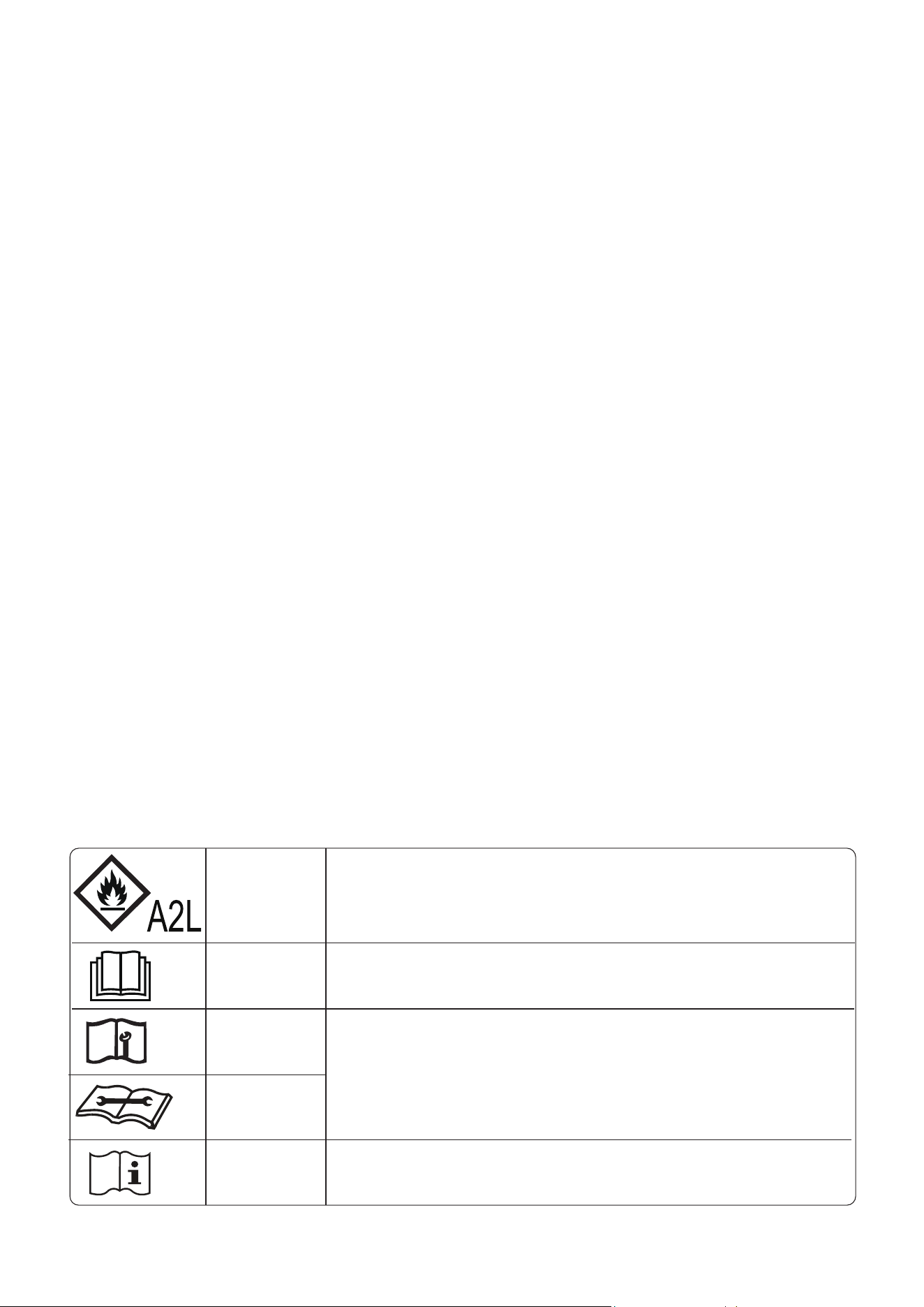
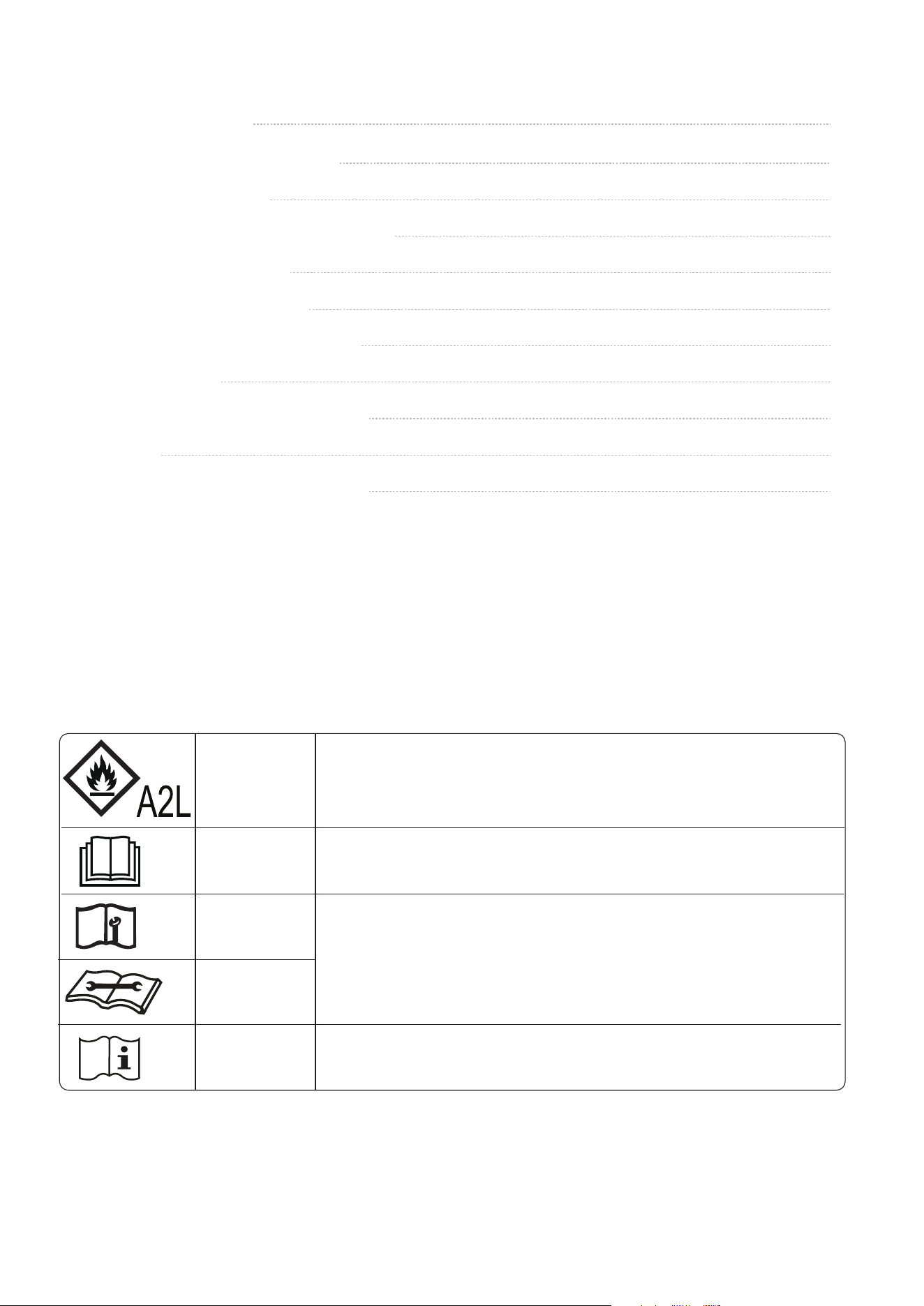
WARNING
This symbol shows that this appliance used a flammable
refrigerant. If the refrigerant is leaked and exposed to an
external ignition source, there is a risk of fire.
This symbol shows that the operation manual should be
read carefully.
This symbol shows that information is available such as
the operating manual or installation manual.
This symbol shows that a service personnel should be
handling this equipment with reference to the
installation manual.
Explanation of symbols displayed on the indoor unit or outdoor unit
13
Indoor Unit Display
Get to Know Your AC.
Dierent models have dierent front panel and display window. Not all the indicators describing
below are available for the air conditioner you purchased. Please check the indoor display window
of the unit you purchased.
Illustrations in this manual are for explanatory purposes. The actual shape of your indoor unit may
be slightly dierent. The actual shape shall prevail.
●
●
NOTE
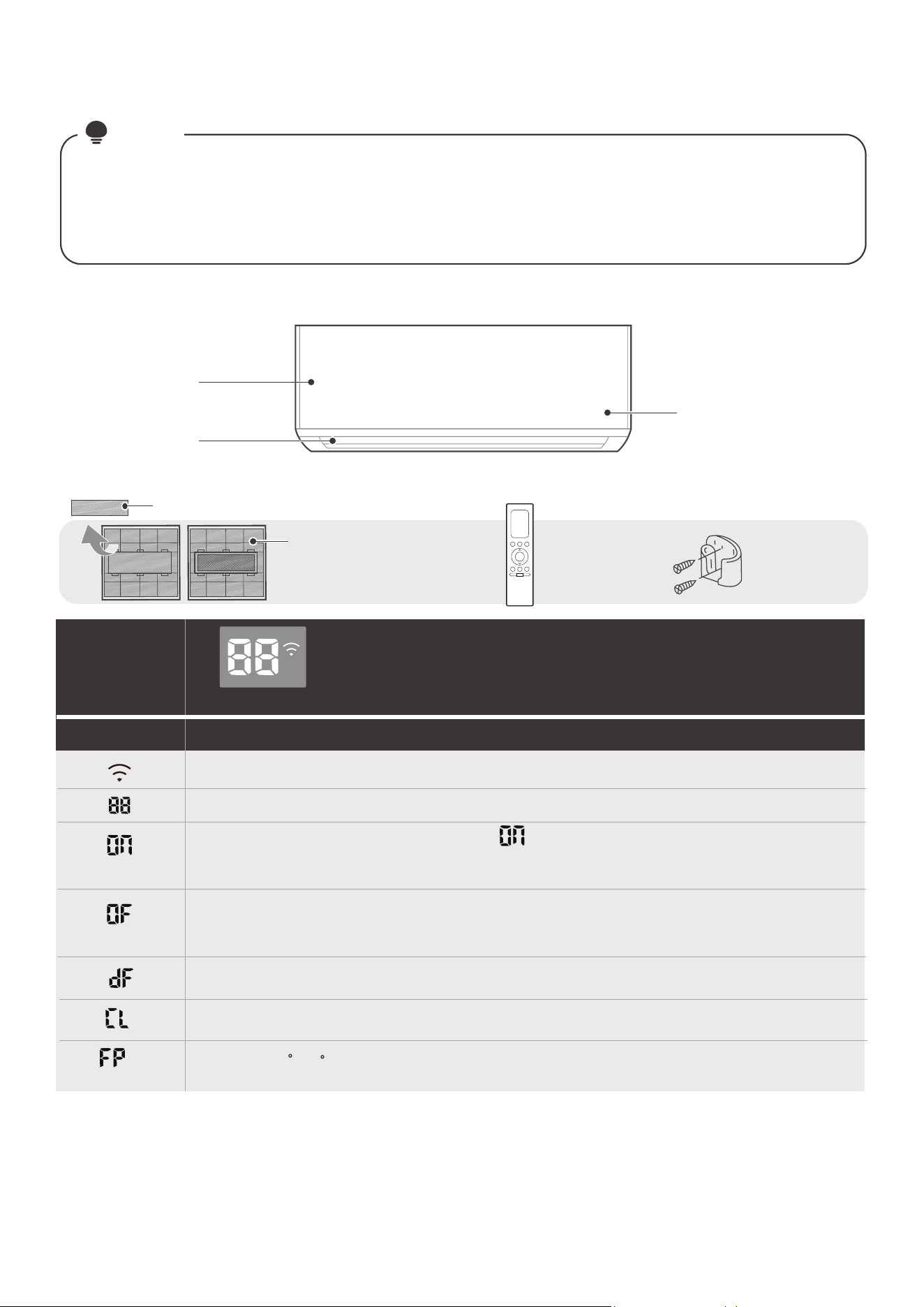
Front Panel
Display Code Meanings
Display
Window
Display Code
(for 3s when)
(for 3s when)
●
●
●
●
●
●
●
●
●
When Wireless Control feature is activated(For APP control units).
SWING, TURBO or SILENCE feature is turned on.
TIMER ON is set (if the unit is OFF, remains on when TIMER ON is set ).
“ ”
TIMER OFF is set.
SWING, TURBO or SILENCE feature is turned o.
When defrosting.
When Active Clean feature is turned on.
When 46 F(8 C) heating feature is turned on.
Displays temperature, operation feature and Error codes:
Display window
Air Outlet
Functional Filter
(On Back of Main Filter-Some Units)
Remote Control Holder
(purchase separately)
Remote Controller
Air Filter
More Features
14
NOTE
●
●
●
●
●
●
Auto-Restart
If the unit loses power, it will automatically
restart with the prior settings once power has
been restored.
Wireless Control(For App control units)
Wireless control allows you to control your air
conditioner using your mobile phone and a
wireless connection.
Louver Angle Memory
Note: Error codes of “EHC1”, “EHC2”,“EHC3”
and “ECC1” are only applicable to the units with
refrigerant sensor.
Heat exchanger dust removal function:
When turning on your unit, the louver will
automatically resume its former angle.
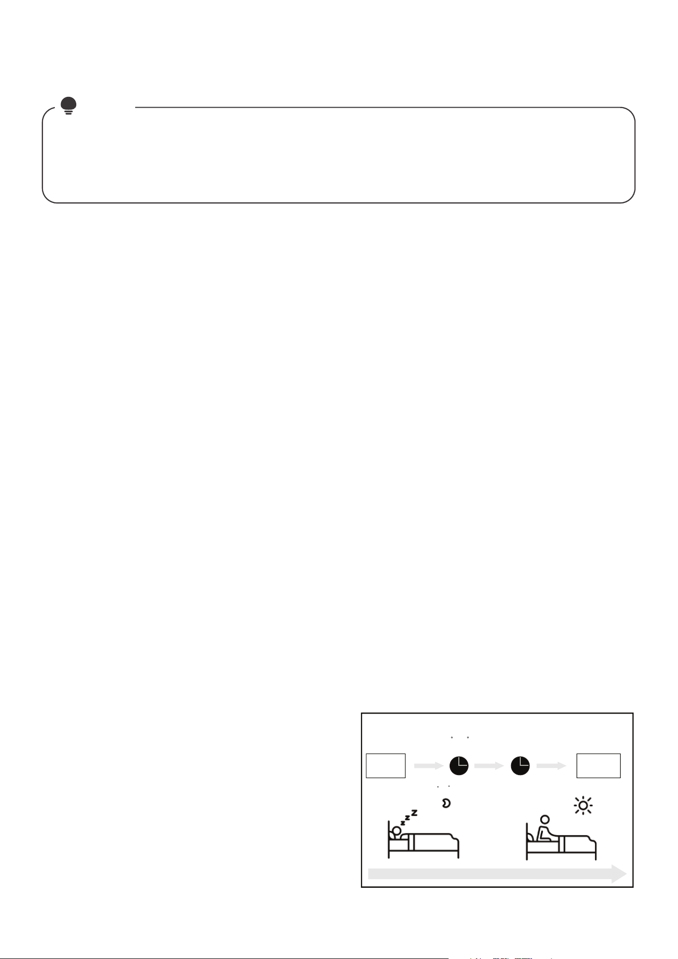
The SLEEP function is used to decrease energy
use while you sleep (and don’t need the same
temperature settings to stay comfortable).
Press the SLEEP button on remote control when
in COOL mode, the unit will increase the tem-
perature by 1°C (2°F) after 1 hour, and will
increase an additional 1°C (2°F) after another
hour.
When in HEAT mode, the unit will decrease the
temperature by 1°C (2°F) after 1 hour, and will
decrease an additional 1°C (2°F) after another
hour.
Sleep Operation
For the USB device access, replacement,
maintenance operations must be carried
out by professional sta.
Set
temperature
1hr 1hr
Keep
running
SLEEP Operation
Saving energy during sleep
Heat mode( -1 C/2 F) per hour for the first two hours
Cool mode(+1 C/2 F) per hour for the first two hours
The sleep feature will stop after 8 hours and
the system will keep running with final situation.
Breeze Away
This feature avoids direct air flow blowing on
the body and make you feel indulging in
silky coolness.
• Active Clean function
-- The Active Clean Technology washes away
dust when it adheres to the heat exchanger by
automatically freezing and then rapidly thawing
the frost. A “pi-pi” sound will be heard.
The Active clean operation is used to produce
more condensed water to improve the cleaning
eect, and the cold air will blow out. After
cleaning, the internal wind wheel then keeps
operating with hot air to blow-dry the
evaporator, thus keeping the inside clean.
-- When this function is turned on, the indoor
unit display window appears “CL ” , after 20
to 45 minutes, the unit will turn o
automatically and cancel Active Clean function.
This feature helps keep the outdoor coil cleaner
and may extend the duration between regular
maintenance intervals depending on local
conditions. When the unit is turned o, a 10
second delay occours then the outdoor fan runs
in reverse rotation for 70 seconds to blow o
loose accumulated dust and debris.
Every time the air conditioner is powered on, a buzzing sound will be heard to indicate that the
product has been powered on normally. If there is no sound, it is possible that the unit is abnormal.
Please power on again or check the circuit.
The actual functions are subject to the product you purchased, please check the indoor display and
remote control of your AC. See the <Remote Controller Manual> for more features.
●
Refrigerant Leakage Detection
- When the system detects a malfunction of the
refrigerant, the indoor unit will automatically
display the following error codes:
“EL0C(System lacks refrigerant )” ,
“EHC1(Refrigerant sensor detects leakage)”,
“EHC2(Working condition of the refrigerant
sensor is out of range and leakage is detected)”,
“EHC3(Working condition of the refrigerant
sensor is out of range )”, or
“ECC1(Other indoor unit refrigerant sensor
detects leakage (Multi-zone)”.
- When “EHC1” or “EHC2” error occurs, the
buzzer will continue to beep for 5 to 6 minutes
before stopping. You can also press any button
on the remote controller to stop the buzzer.
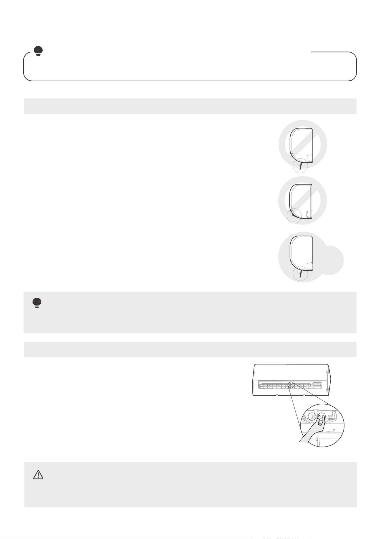
Setting Angle of Air Flow
While the unit is on, use the SWING/DIRECT button on remote control to set the direction (vertical
angle) of airflow. Please refer to the Remote Control Manual for details.
NOTE
: Setting vertical angle of air flow(Remote control)
15
Setting horizontal angle of air flow(Manual operation)
Do not put your fingers in or near the blowerand suction side of the unit. The high-speed fan
inside the unit may cause injury.
NOTE ON LOUVER ANGLES
●
Do not set louver at too vertical an angle for long periods of time
When using COOL or DRY mode. It would be condense the water
on the louver blade, which will drop on your floor or furnishings.
●
Setting the louver at too small an angle when using COOL or HEAT
mode, can reduce the performance of the AC due to restricted
air flow.
CAUTION
Do not move louver by hand. You can turn o the unit and unplug it for a few seconds to restart
the unit. It will be reset the louver when you try.
NOTE
●
According to the relative standards requirement, please sets the
vertical air flow louver to its maximum angle under heating
capacity test.
Heating
Capacity
Test
The horizontal angle of the airflow must be set
manually. Grip the deflector rod and manually
adjust it to your preferred direction.
The horizontal angle of the airflow can be set by
remote control. please refer to the Remote Control
Manual.
Deflector rod
Manual Operation(without remote)
16
The manual button is intended for testing purposes and emergency operation only. Please do
not use this function unless the remote control is lost and it is absolutely necessary. To restore
regular operation, use the remote control to activate the unit. Unit must be turned o before
manual operation.
For product use
CAUTION :
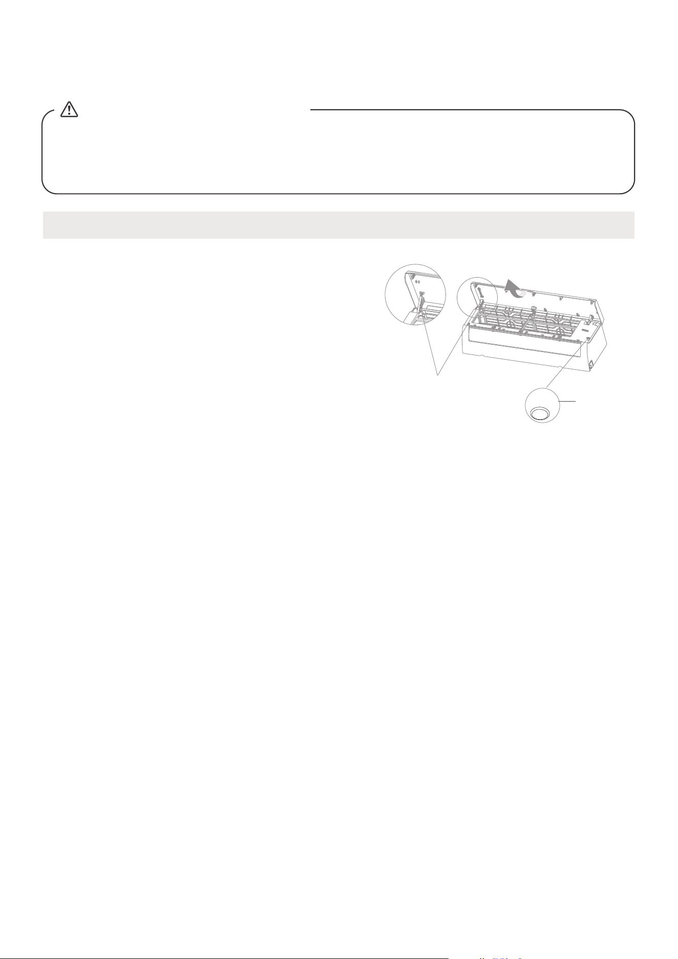
To operate your unit manually:
Open the front panel of the indoor unit.
Note: If there is a supporting rod located
on the left or right side. Please use it to
prop up the panel.
Locate the MANUAL CONTROL button on the
right-hand side of the unit.
Press the MANUAL CONTROL button one time to
activate FORCED AUTO mode.
Press the MANUAL CONTROL button again to
activate FORCED COOLING mode.
Press the MANUAL CONTROL button a third time
to turn the unit o.
Release the supporting rod(if any), then close the
front panel.
●
●
●
●
●
●
Manual
control
button
Supporting rod
(located on the
left or right,
model dependent )
AUTO/COOL
Care and Maintenance
17
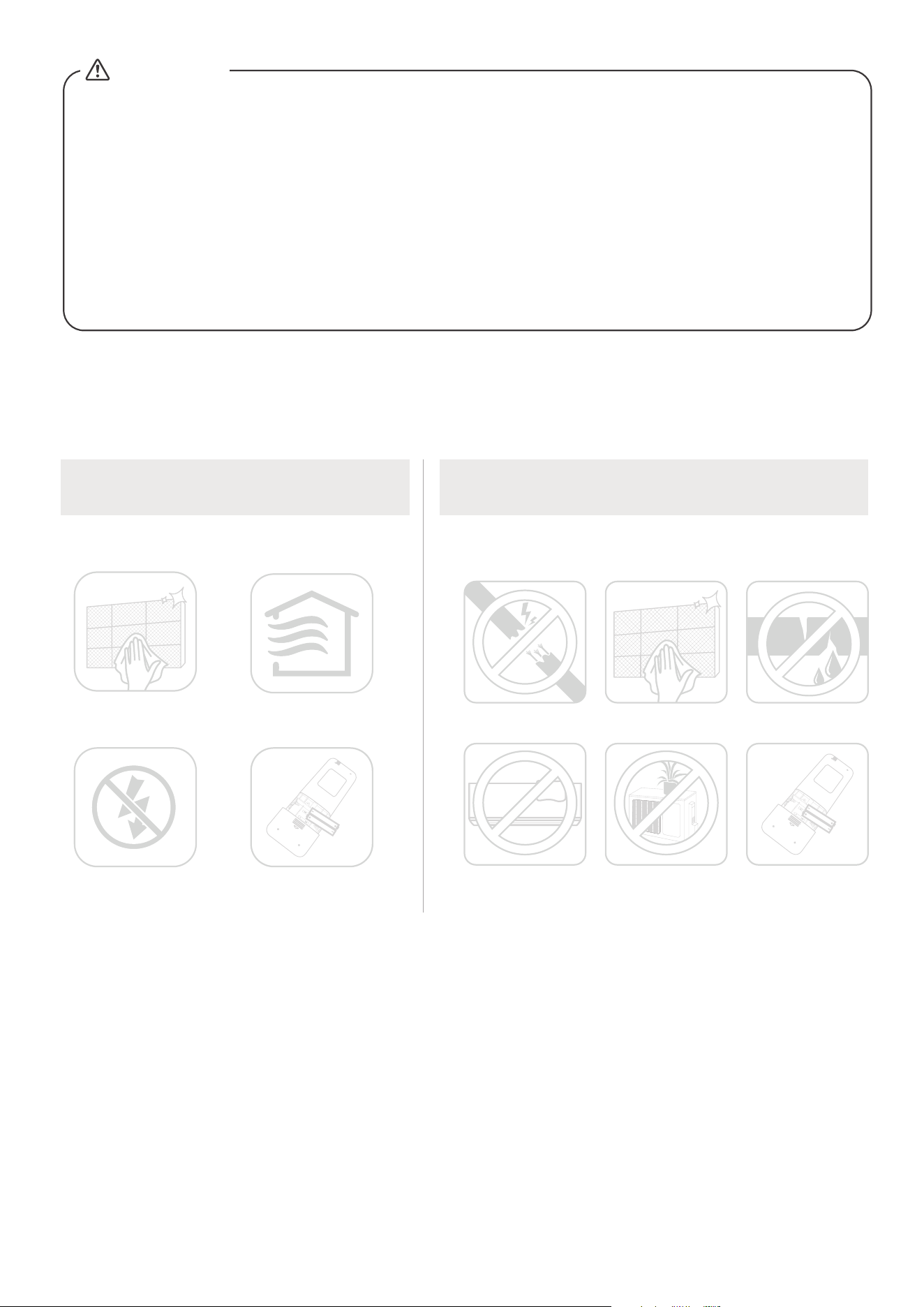
Cleaning Your Indoor Unit, Air Filter
CAUTION
• The cooling eciency of your unit and your health would be damaged for the
glogged AC. Make sure to clean the filter every two weeks.
• Always TURN OFF your AC system and disconnect its power supply before
cleaning or maintenance.
• Do not touch air freshening (Plasma) filter at least 10 minutes after turning o
the unit.
• Only use a soft, dry cloth to wipe the unit clean. You can use a cloth soaked in
warm water to wipe it clean if the unit is especially dirty.
• Do not use chemicals or chemically treated cloths to clean the unit
• Do not use benzene, paint thinner, polishing powder or other solvents to clean
the unit. They can cause the plastic surface to crack or deform.
• Do not use water hotter than 104°F(40°C) to clean the front panel. This can
cause the panel to deform or become discolored.
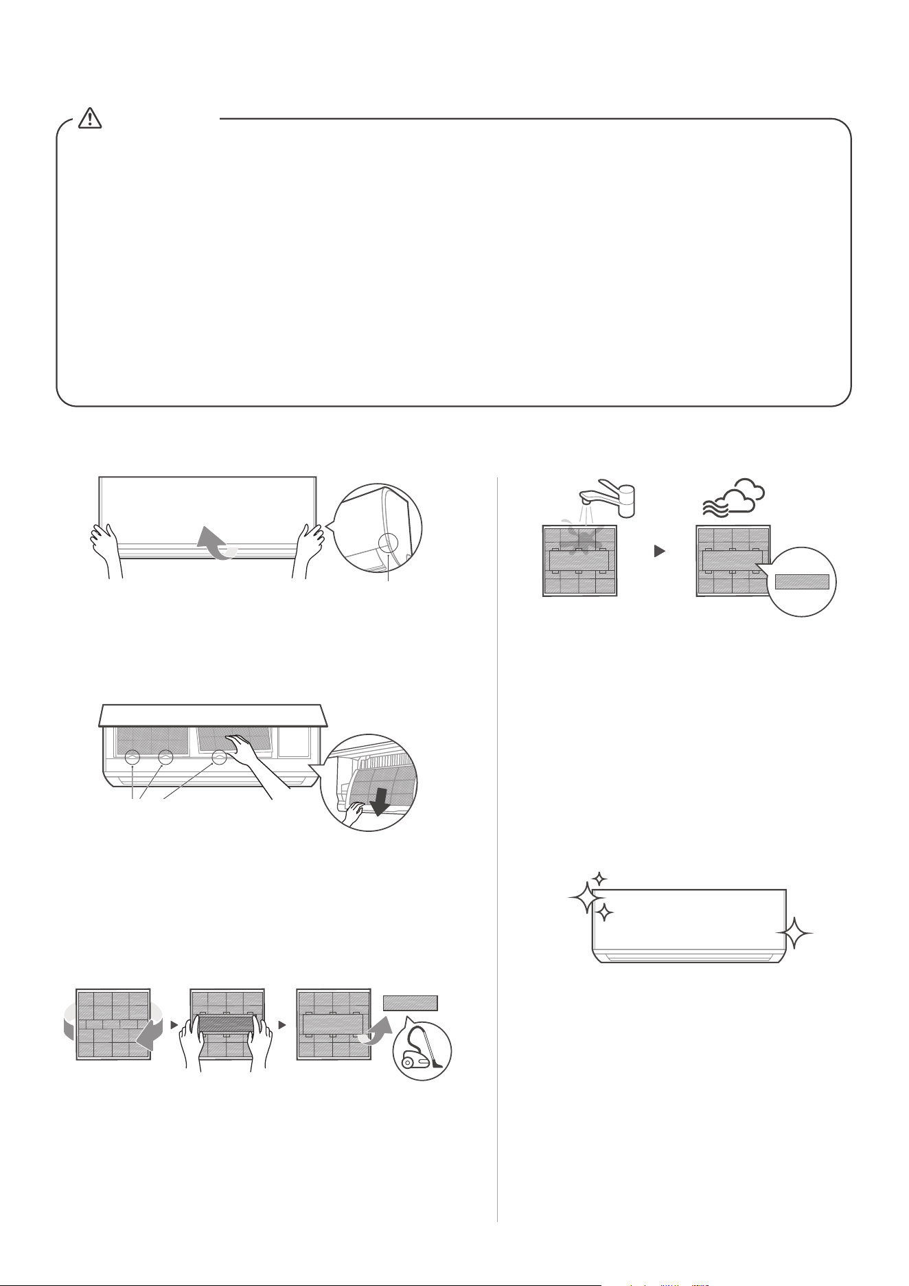
Lift the front panel of the indoor unit. For the unit with
supporting rod, please use it to prop up the front panel.
If your filter has a small air freshening filter, unclip it
from the larger filter. Clean this air freshening filter
with a hand-held vacuum.
Grip the tab on the end of the filter, lift it up, then pull
it towards yourself and pull the filter out.
Step 1:
Step 3:
Clean the large air filter with warm, soapy
water. Be sure to use a mild detergent.
Rinse the filter with fresh water, then shake
o excess water. Dry it in a cool, dry place,
and refrain from exposing it to direct
sunlight.
Step 4:
When dry, re-clip the air freshening filter
to the larger filter, then slide it back into
the indoor unit. Finally, Close the front
panel of the indoor unit.
Step 5:
Step 2:
Grab the clasp
and lift
Filter Tabs
(Front)
1. Flip to back 2. Remove air
freshening filter
o
3. Clean it by
vacuum cleaner
(Back)
Don't forget to
install me back
18
Maintenance –
Long Periods of Non-Use
If you plan not to use your air conditioner for
an extended period of time, do the following:
Clean all filters Turn on FAN function until
unit dries out completely
Turn o the unit and
disconnect the power
Remove batteries
from remote control
Maintenance –
Pre-Season Inspection
After long periods of non-use, or before periods of
frequent use, do the following:
Check for damaged wires
Clean all filters Check for leaks
Replace batteriesMake sure nothing is blocking
all air inlets and outlets
Maintenance your AC.
CAUTION
• Before changing the filter or cleaning, turn o the unit and disconnect its
power supply.
• When removing filter, do not touch metal parts in the unit. The sharp metal
edges can cut you.
• Do not use water to clean the inside of the indoor unit. This can destroy
insulation and cause electrical shock.
• Do not expose filter to direct sunlight when drying. This can shrink the filter.
• Any maintenance and cleaning of outdoor unit should be performed by an
authorized dealer or a licensed service provider.
• Any unit repairs should be performed by an authorized dealer or a licensed
service provider.
Troubleshooting
19
Common Issues
The following problems are not a malfunction and in most situations will not require repairs.
Issue Possible Causes
Unit does not turn
on when pressing
ON/OFF button
The Unit has a 3-minute protection feature that prevents the unit from
overloading. The unit cannot be restarted within three minutes of being
turned o.
The unit may change its setting to prevent frost from forming on the unit.
Once the temperature increases, the unit will start operating in the
previously selected mode again.
The set temperature has been reached, at which point the unit turns o the
compressor. The unit will continue operating when the temperature
fluctuates again.
The indoor unit
emits white mist
In humid regions, a large temperature dierence between the room’s air
and the conditioned air can cause white mist.
Both the indoor and
outdoor units emit
white mist
When the unit restarts in HEAT mode after defrosting, white mist may be
emitted due to moisture generated from the defrosting process.
The unit changes from
COOL/HEAT mode to
FAN mode
The indoor unit makes
noises
A rushing air sound may occur when the louver resets its position.
A squeaking sound may occur after running the unit in HEAT mode due to
expansion and contraction of the unit’s plastic parts.
Both the indoor unit
and outdoor unit make
noises
Low hissing sound during operation: This is normal and is caused by
refrigerant gas flowing through both indoor and outdoor units.
Low hissing sound when the system starts, has just stopped running, or is
defrosting: This noise is normal and is caused by the refrigerant gas
stopping or changing direction.
Squeaking sound: Normal expansion and contraction of plastic and metal
parts caused by temperature changes during operation can cause
squeaking noises.
CAUTION
If any of the following conditions occurs, turn o your unit immediately!
• The wire is damaged or abnormally warm
• You smell a burning odor
• The unit emits loud or abnormal sounds
• A power fuse blows or the circuit breaker frequently trips
• Water or other objects fall into or out of the unit
DO NOT ATTEMPT TO FIX THESE YOURSELF! CONTACT AN AUTHORIZED
SERVICE PROVIDER IMMEDIATELY.
20
Issue Possible Causes
The outdoor unit
makes noises
The unit will make dierent sounds based on its current operating mode.
Dust is emitted from
either the indoor or
outdoor unit
The unit may accumulate dust during extended periods of non-use, which will
be emitted when the unit is turned on. This can be mitigated by covering the
unit during long periods of inactivity.
The unit emits a
bad odor
The unit may absorb odors from the environment (such as furniture, cooking,
cigarettes, etc.) which will be emitted during operations.
The unit’s filters have become moldy and should be cleaned.
The fan of the outdoor
unit does not operate
During operation, the fan speed is controlled to optimize product operation.
Operation is erratic,
unpredictable, or
unit is unresponsive
Interference from cell phone towers and remote boosters may cause the unit
to malfunction.
In this case, try the following:
•
Disconnect the power, then reconnect.
•
Press ON/OFF button on remote control to restart operation.
NOTE: If problem persists, contact a local dealer or your nearest customer service center. Provide them
with a detailed description of the unit malfunction as well as your model number.
When troubles occur, please check the following points before contacting a
repair company.
Problem Possible Causes Solution
Poor Cooling
Performance
Temperature setting may be higher
than ambient room temperature
Lower the temperature setting
The heat exchanger on the indoor
or outdoor unit is dirty
Use Clean function by remote control to
clean the aected heat exchanger
The air filter is dirty
Remove the filter and clean it according to
instructions
The air inlet or outlet of either
unit is blocked
Turn the unit o, remove the obstruction
and turn it back on
Doors and windows are open
Make sure that all doors and windows are
closed while operating the unit
Excessive heat is generated
by sunlight
Close windows and curtains during periods
of high heat or bright sunshine
Too many sources of heat in the
room (people, computers,
electronics, etc.)
Reduce amount of heat sources
Low refrigerant due to leak
or long-term use
Check for leaks, re-seal if necessary and
top o refrigerant
SILENCE function is activated
(optional function)
SILENCE function can lower product
performance by reducing operating
frequency. Turn o SILENCE function.
CAUTION
21
Error code appears and
begins with the letters
as the following in the
window display of
indoor unit:
E(x), P(x), F(x)
EH(xx), EL(xx), EC(xx)
PH(xx), PL(xx), PC(xx)
•
•
•
Problem Possible Causes Solution
The unit is not
working
Power failure
Wait for the power to be restored
The power is turned o Turn on the power
The fuse is burned out
Call service center to replace the fuse
Remote control batteries are dead
Replace batteries
The Unit’s 3-minute protection
has been activated
Wait three minutes after restarting
the unit
Timer is activated
Turn timer o
The unit starts and
stops frequently
There’s too much or too little
refrigerant in the system
Call service center to check for leaks
and recharge the system with
refrigerant.
Incompressible gas or moisture
has entered the system.
Call service center to evacuate and
recharge the system with refrigerant
The compressor is broken
Call service center to replace the
compressor
The voltage is too high or
too low
Install a manostat to regulate the
voltage
Poor heating
performance
The outdoor temperature is
extremely low
Use auxiliary heating device
Cold air is entering through
doors and windows
Make sure that all doors and
windows are closed during use
Low refrigerant due to leak or
long-term use
Call service center to check for leaks,
re-seal if necessary and top o
refrigerant
Indicator lamps
continue flashing
The unit may stop operation or continue to run safely. If the indicator
lamps continue to flash or error codes appear, wait for about 10
minutes. The problem may resolve itself.
If not, disconnect the power, then connect it again. Turn the unit on.
If the problem persists, disconnect the power and contact your nearest
customer service center.
NOTE: If your problem persists after performing the checks and diagnostics above, turn o your unit
mmediately and contact an authorized service center.
Safety Precautions
23
Installation Instructions
22
Let's Start Installing Your AC
31
Installation Overview
32
Install Your Indoor Unit
35
Install Your Outdoor Unit
45
Refrigerant Piping Connection
49
Air Evacuation
53
Electrical and Gas Leak Checks
55
Test Run
56
Packing and Unpacking The Unit
57
33
Installation Summary - Indoor Unit
CAUTION
CAUTION
CAUTION
CAUTION
WARNING
This symbol shows that this appliance used a flammable
refrigerant. If the refrigerant is leaked and exposed to an
external ignition source, there is a risk of fire.
This symbol shows that the operation manual should be
read carefully.
This symbol shows that information is available such as
the operating manual or installation manual.
This symbol shows that a service personnel should be
handling this equipment with reference to the
installation manual.
Explanation of symbols displayed on the indoor unit or outdoor unit
Safety Precautions
23
It is really important you read Safety Precautions Before Operation and Installation
Incorrect installation due to ignoring instructions can cause serious damage or injury.
The seriousness of potential damage or injuries is classified as either a WARNING
or CAUTION.
WARNING
CAUTION
Explanation of Symbols
WARNING
This appliance is not intended for use by persons(including children) with reduced
physical, sensory or mental capabilities, or lack of experience and knowledge, unless
they have been given supervision or instruction concerning use of the appliance by
a person responsible for their safety. Children should be supervised to ensure that
they do not play with the appliance.
This symbol indicates the possibility of personal injury or loss of
life.
This symbol indicates the possibility of property damage or serious
consequences.
ELECTRICAL WARNINGS
Only use the specified wire. If the wire is damaged, it must be replaced by the
manufacturer, its service agent or similarly qualified persons in order to avoid a
hazard.
The product must be properly grounded at the time of installation, or electric
shock may occur.
For all electrical work, follow all local and national wiring standards, regulations,
and the Installation Manual. Connect cables tightly, and clamp them securely to
prevent external forces from damaging the terminal. Improper electrical
connections can overheat and cause fire, and may also cause shock. All electrical
connections must be made according to the Electrical Connection Diagram
located on the panels of the indoor and outdoor units.
All wiring must be properly arranged to ensure that the control board cover can
close properly. If the control board cover is not closed properly, it can lead to
corrosion and cause the connection points on the terminal to heat up, catch fire,
or cause electrical shock.
Disconnection must be incorporated in the fixed wiring in accordance with the
wiring rules.
Do not share the electrical outlet with other appliances. Improper or insucient
power supply can cause fire or electric shock.
If connecting power to fixed wiring, an all-pole disconnection device which has
at least 3mm clearances in all poles, and have a leakage current that may exceed
10mA, the residual current device(RCD) having a rated residual operating current
not exceeding 30mA, and disconnection must be incorporated in the fixed wiring
in accordance with the wiring rules.
●
●
●
●
●
●
●
24
WARNINGS FOR PRODUCT INSTALLATION
Installation must be performed by an authorized dealer or specialist. Defective
installation can cause water leakage, electrical shock, or fire.
Installation must be performed according to the installation instructions.
Improper installation can cause water leakage, electrical shock, or fire.
Contact an authorized service technician for repair or maintenance of this unit.
This appliance shall be installed in accordance with national wiring regulations.
Only use the included accessories, parts, and specified parts for installation.
Using non-standard parts can cause water leakage, electrical shock, fire, and can
cause the unit to fail.
Install the unit in a firm location that can support the unit’s weight. If the chosen
location cannot support the unit’s weight, or the installation is not done properly,
the unit may drop and cause serious injury and damage.
Install drainage piping according to the instructions in this manual. Improper
drainage may cause water damage to your home and property.
For units that have an auxiliary electric heater, do not install the unit within 1
meter (3 feet) of any combustible materials.
For the units that have a wireless network function, the USB device access,
replacement, maintenance operations must be carried out by professional sta.
Do not install the unit in a location that may be exposed to combustible gas leaks.
If combustible gas accumulates around the unit, it may cause fire.
Do not turn on the power until all work has been completed.
When moving or relocating the air conditioner, consult experienced service
technicians for disconnection and reinstallation of the unit.
How to install the appliance to its support, please read the information for details
in "indoor unit installation" and "outdoor unit installation" sections .
●
●
●
●
●
●
●
●
●
●
●
●
●
●
●
●
●
WARNING FOR USING FLAMMABLE REFRIGERANTS
Do not use means to accelerate the defrosting process or to clean, other than
those recommended by the manufacturer.
The appliance shall be stored in a room without continuously operating ignition
sources (for example: open flames, an operating gas appliance or an operating
electric heater).
Do not pierce or burn.
Be aware that refrigerants may not contain an odour.
TAKE NOTE OF FUSE SPECIFICATIONS
The air conditioner’s circuit board (PCB) is designed with a fuse to provide
overcurrent protection. The specifications of the fuse are printed on the circuit board ,
for example : T3.15AL/250VAC, T5AL/250VAC, T3.15A/250VAC, T5A/250VAC,
T20A/250VAC, T30A/250VAC,etc.
NOTE: Only the blast-proof ceramic fuse can be used.
Turn o the air conditioner and disconnect the power before performing any
installation or repairing. Failure to do so can cause electric shock.
25
For R454B refrigerant charge amount and minimum room area:
The machine you purchased may be one of the types in the table below. The indoor
and outdoor units are designed to be used together. Please check the machine you
purchased.The indoor unit should be installed at least 6.0ft /1.8m above from the
floor, the height of the room cannot be less than 7.3ft /2.2m, and the minimum
room area of operating or storage should be as specified in the following table.
A
min
[ft2/m2]
m
c or
mREL
[oz/kg]
6.0~7.3/
1.8~2.2
7.6/2.3 7.9/2.4 8.6/2.6 9.2/2.8 9.9/3.0
<=62.6/1.776
63.4/1.8 60/5.53 57/5.29 55/5.07 51/4.68 47/4.35 44/4.06
70.5/2.0 67/6.15 64/5.88 61/5.64 56/5.2 52/4.83 49/4.51
77.5/2.2 73/6.76 70/6.47 67/6.2 62/5.72 58/5.31 54/4.96
84.6/2.4 80/7.38 76/7.06 73/6.76 68/6.24 63/5.8 59/5.41
91.7/2.6 86/7.99 83/7.64 79/7.32 73/6.76 68/6.28 64/5.86
98.7/2.8 93/8.6 89/8.23 85/7.89 79/7.28 73/6.76 68/6.31
105.8/3.0 100/9.22 95/8.82 91/8.45 84/7.8 78/7.24 73/6.76
112.8/3.2 106/9.83 102/9.41 97/9.01 90/8.32 84/7.73 78/7.21
119.9/3.4 113/10.45 108/9.99 104/9.58 96/8.84 89/8.21 83/7.66
126.9/3.6 120/11.06 114/10.58 110/10.14 101/9.36 94/8.
69 88/8.11
134/3.8 126/11.68 121/11.17 116/10.7 107/9.88 99/9.17 93/8.56
141.1/4.0 133/12.29 127/11.76 122/11.27 112/10.4 104/9.66 97/9.01
148.1/4.2 139/12.9 133/12.34 128/11.83 118/10.92 110/10.14 102/9.46
155.1/4.4 146/13.52 140/12.93 134/12.39 124/11.44 115/10.62 107/9.91
162.2/4.6 153/14.13 146/13.52 140/12.96 129/11.96 120/11.11 112/10.37
169.2/4.8 159/14.75 152/14.11 146/13.52 135/12.48 125/11.59 117/10.82
176.3/5.0 166/15.36 159/14.69 152/14.08 140/13 130/12.07 122/11.27
Area
formula
h
inst
[ft/m]
12/1.10
A
min
is the required minimum room area in ft /m
m
c
is the actual refrigerant charge in the system in oz/kg
m
REL is the refrigerant releaseable charge in oz/kg
(Applicable to the
units with refrigerant sensors only)
h
inst
is the height of the bottom of the appliance relative to the floor of
the room after installation.
WARNING: The minimum room area or minimum room area of
conditioned space is based on releasable charge and total
system refrigerant charge.
2 2
26
Indoor unit Outdoor unit
09K
12K
ECOWAL09DA ECOSZ109DA
18K
Model
295CFM
245CFM
400CFM
ECOSZ112DA
ECOWAL12DA
ECOWAL18DA ECOSZ118DA
24K
545CFM
ECOWAL24DA ECOSZ124DA
Indoor Nominal air volume
For the units with refrigerant sensors, when the unit detects a refrigerant leak, the
minimum airflow of the indoor unit is as follows:
Entry Tier Series
Indoor unit Outdoor unit
09K
12K
18K
Model
24K
The information in the following table is only applicable to models without
refrigerant sensors:
Entry Tier Series
27
ECOWAL09DA ECOSZ109DA
ECOSZ112DA
ECOWAL12DA
ECOWAL18DA ECOSZ118DA
ECOWAL24DA ECOSZ124DA

28
1.
Installation(where refrigerant pipes are allowed)
- Any person who is involved with working on or breaking into a refrigerant
circuit should hold a current valid certificate from an industry-accredited
assessment authority, which authorises their competence to handle refrigerants
safely in accordance with an industry recognised assessment specification.
- Maintenance and repair requiring the assistance of other skilled personnel shall
be carried out under the supervision of the person competent in the use of
flammable refrigerants.
- That the installation of pipe-work shall be kept to a minimum.
- That pipe-work shall be protected from physical damage.
- Where refrigerant pipes shall be compliance with national gas regulations.
- That mechanical connections shall be accessible for maintenance purposes.
- Be more careful that foreign matter(oil, water,etc) does not enter the piping.
Also, when storing the piping, securely seal the opening by pinching, taping, etc.
- All working procedure that aects safety means shall only be carried by
competent persons.
- Appliance shall be stored in a well ventilated area where the room size
corresponds to the room area as specifiec for operation.
- Joints shall be tested with detection equipment with a capability of 5 g/year of
refrigerant or better, with the equipment in standstill and under operation or
under a pressure of at least these standstill or operation conditions after
installation. Detachable joints shall NOT be used in the indoor side of the unit
(brazed, welded joint could be used).
- In cases that require mechanical ventilation, ventilation openings shall be kept
clear of obstruction.
- LEAK DETECTION SYSTEM installed. Unit must be powered except for service.
When the refrigerant sensor detects refrigerant leakage, the indoor unit will
display a error code and emit a buzzing sound, the compressor of outdoor unit
will immediately stop, and the indoor fan will start running. The service life of the
refrigerant sensor is 15 years. When the refrigerant sensor malfunctions, the
indoor unit will display the error code “FHCC”. The refrigerant sensor can not be
repaired and can only be replaced by the manufacture. It shall only be replaced
with the sensor specified by the manufacture.(Applicable to the units with
refrigerant sensor only)
2. When a FLAMMABLE REFRIGERANT is used, the requirements for installation
space of appliance and/or ventilation requirements are determined according to
- the mass charge amount(M) used in the appliance,
- the installation location,
- the type of ventilation of the location or of the appliance.
a. The minimum test pressure for the low side of the system shall be the low side
- piping material, pipe routing, and installation shall include protection from
physical damage in operation and service, and be in compliance with national
and local codes and standards, such as ASHRAE 15, IAPMO Uniform
Mechanical Code, ICC International Mechanical Code, or CSA B52. All field
joints shall be accessible for inspection prior to being covered or enclosed.
- that protection devices, piping, and fittings shall be protected as far as
possible against adverse environmental eects, for example, the danger of
water collecting and freezing in relief pipes or the accumulation of dirt and debris;
- that piping in refrigeration systems shall be so designed and installed to
minimize the likelihood of hydraulic shock damaging the system;
- that steel pipes and components shall be protected against corrosion with a
rustproof coating before applying any insulation;
- that precautions shall be taken to avoid excessive vibration or pulsation;
- the minimum floor area of the room shall be mentioned in the form of a table
or a single figure without reference to a formula;
- after completion of field piping for split systems, the field pipework shall be
pressure tested with an inert gas and then vacuum tested prior to refrigerant
charging, according to the following requirements:

29
design pressure and the minimum test pressure for the high side of the system
shall be the high side design pressure, unless the high side of the system can not
be isolated from the low side of the system in which case the entire system
shall be pressure tested to the low side design pressure.
b. The test pressure after removal of pressure source shall be maintained for at
least 1 h with no decrease of pressure indicated by the test gauge, with test
gauge resolution not exceeding 5% of the test pressure.
c. During the evacuation test, after achieving a vacuum level specified in the
manual or less, the refrigeration system shall be isolated from the vacuum pump
and the pressure shall not rise above 1500 microns within 10 min. The vacuum
pressure level shall be specified in the manual, and shall be the lessor of 500
microns or the value required for compliance with national and local codes and
standards, which may vary between residential, commercial,and industrial
buildings.
- field-made refrigerant joints indoors shall be tightness tested according to the
following requirements: The test method shall have a sensitivity of 5 grams per
year of refrigerant or better under a pressure of at least 0,25 times the
maximum allowable pressure. No leak shall be detected.
3 . Qualification of workers
Any maintenance, service and repair operations must be required qualification
of the working personnel. Every working procedure that aects safety means
shall only be carried out by competent persons that joined the training and
achieved competence should be documented by a certificate. The training of
these procedures is carried out by national training organizations or
manufacturers that are accredited to teach the relevant national competency
standards that may be set in legislation. All training shall follow the ANNEX HH
requirements of UL 60335-2-40 4th Edition.
Examples for such working procedures are:
• breaking into the refrigerating circuit;
• opening of sealed components;
• opening of ventilated enclosures.
4. Ventilated area
Ensure that the area is in the open or that it it adequately ventilated before breaking
into the system or conducting any hot work. A degree of ventilation shall continue
during the period that the work is carried out. The ventilation should safely disperse
any released refrigerant and preferably expel it externally into the atmosphere.
5. Cabling
Check that cabling will not be subject to wear, corrosion, excessive pressure,
vibration, sharp edges or any other adverse environmental eects. The check shall
also take into account the eects of aging or continual vibration from sources such
as compressors or fans.
6. Detection of flammable refrigerants
Under no circumstances shall potential sources of ignition be used in the searching
for or detection of refrigerant leaks. A halide torch(or any other detector using a
naked flame) shall not be used.
The following leak detection methods are deemed acceptable for refrigerant
systems. Electronic leak detectors may be used to detect refrigerant leaks but, in
the case of FLAMMABLE REFRIGERANTS, the sensitivity may not be adequate, or
may need re-calibration. (Detection equipment shall be calibrated in a refrigerant-
free area.) Ensure that the detector is not a potential source of ignition and is
suitable for the refrigerant used. Leak detection equipment shall be set at a
percentage of the LFL of the refrigerant and shall be calibrated to the refrigerant
employed, and the appropriate percentage of gas (25 % maximum) is confirmed.
Leak detection fluids are also suitable for use with most refrigerants but the use of
detergents containing chlorine shall be avoided as the chlorine may react with the
refrigerant and corrode the copper pipe-work.

30
7. Removal and evacuation
When breaking into the refrigerant circuit to make repairs - or for any other purpose
conventional procedures shall be used. However, for flammable refrigerants it is
important that best practice be followed, since flammability is a consideration.
The following procedure shall be adhered to:
safely remove refrigerant following local and national regulations;
evacuate;
purge the circuit with inert gas (optional for A2L);
evacuate (optional for A2L);
continuously flush or purge with inert gas when using flame to open circuit; and
open the circuit
The refrigerant charge shall be recovered into the correct recovery cylinders if
venting is not allowed by local and national codes. For appliances containing
flammable refrigerants, the system shall be purged with oxygen-free nitrogen to
render the appliance safe for flammable refrigerants. This process might need to
be repeated several times. Compressed air or oxygen shall not be used for purging
refrigerant systems.
For appliances containing flammable refrigerants, refrigerants purging shall be
achieved by breaking the vacuum in the system with oxygen-free nitrogen and
continuing to fill until the working pressure is achieved, then venting to atmosphere,
and finally pulling down to a vacuum (optional for A2L). This process shall be
repeated until no refrigerant is within thesystem (optional for A2L). When the final
oxygen-free nitrogen charge is used, the system shall be vented down to
atmospheric pressure to enable work to take place.
The outlet for the vacuum pump shall not be close to any potential ignition sources,
and ventilation shall be available.
8. Charging procedures
In addition to conventional charging procedures, the following requirements shall
be followed:
Works shall be undertaken with appropriate tools only (In case of uncertainty,
please consult the manufacturer of the tools for use with flammable refrigerants)
Ensure that contamination of dierent refrigerants does not occur when using
charging equipment. Hoses or lines shall be as short as possible to minimize the
amount of refrigerant contained in them.
Cylinders shall be kept upright.
Ensure that the refrigeration system is earthed prior to charging the system with
refrigerant.
Label the system when charging is complete(if not already).
Extreme care shall be taken not to overfill the refrigeration system.
Prior to recharging the system it shall be pressure tested with oxygen free nitrogen
(OFN). The system shall be leak tested on completion of charging but prior to
commissioning. A follow up leak test shall be carried out prior to leaving the site.
9. Recovery
When removing refrigerant from a system, either for servicing or decommissioning,
it is recommended good practice that all refrigerants are removed safely.
When transferring refrigerant into cylinders, ensure that only appropriate refrigerant
recovery cylinders are employed. Ensure that the correct number of cylinders for
holding the total system charge is available. All cylinders to be used are designated.
NOTE Examples of leak detection fluids are
- bubble method,
- fluorescent method agents.
If a leak is suspected, all naked flames shall be removed/extinguished.
If a leakage of refrigerant is found which requires brazing, all of the refrigerant shall
be recovered from the system, or isolated (by means of shut o valves) in a part of
the system remote from the leak. See the following instructions of removal of
refrigerant.
Let's Start Installing Your AC
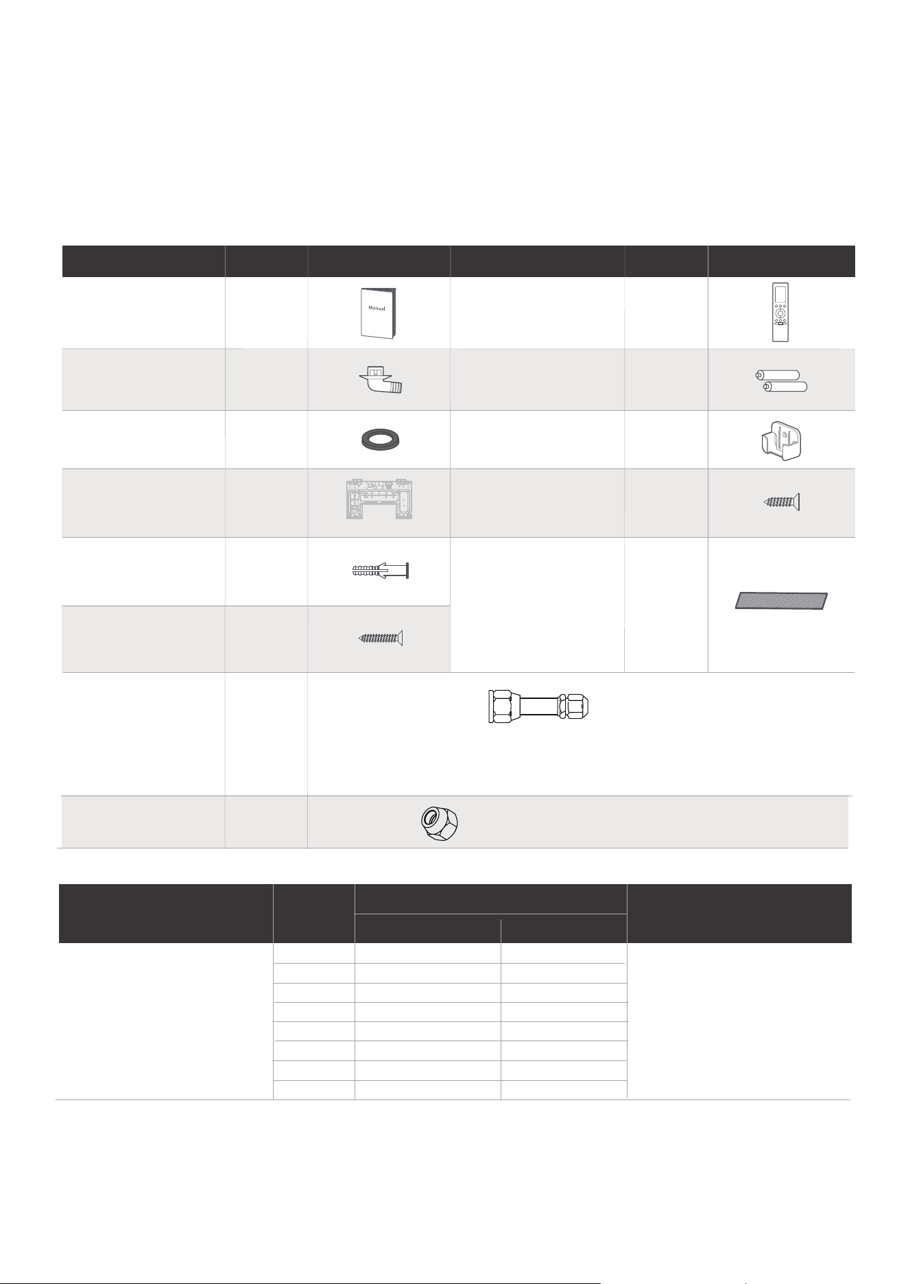
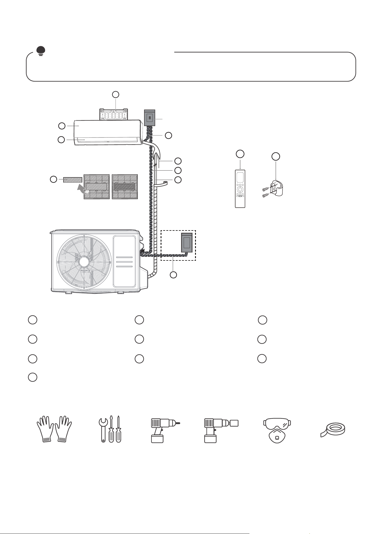
Check over the accessories
The air conditioning system comes with the following accessories. Use all of the installation parts and
accessories to install the air conditioner. Improper installation may result in water leakage, electrical
shock and fire, or cause the equipment to fail. The items are not included with the air conditioner must
be purchased separately.
31
(Need to be installed on
the back of main air filter
by the authorized
technician while installing
the machine)
Mounting plate
fixing screw
Remote controller
Fixing screw for
remote controller
holder(purchase
separately)
Remote controller
holder(purchase
separately)
Drain joint
Seal
Mounting plate +
Cardboard
Manual
2-3
1
1+1
1
Anchor
1
2
1
2
Battery
Small Filter
1~2
5
5
Name of Accessories Name of AccessoriesQ’ty(pc) Shape Q’ty(pc) Shape
1
2
Transfer connector
(Φ19( 3/4in) transfer
to Φ16( 5/8in). Packed
with the indoor unit,
the North America
market 33K hyper heat
unit only. )
NOTE: In North America market, when 33K hyper heat indoor unit matches with
multi-zone condensers, you must purchase pipe with liquid side Φ9.52( 3/8in) and
gas side Φ16( 5/8in).The transfer connector need to be installed on the indoor unit
gas side to meet the pipe size.
Copper nut
NOTE: Used to connect the connecting pipes
between indoor and outdoor units.
Name
Pipe specification
Remark
Parts you must purchase
separately. Consult the dealer
about the proper pipe size of
the unit you purchased.
Connecting pipe
assembly
Liquid side
6K
9K
12K
18K
33K
30K
24K
36K
Model
Gas side
Φ
Φ
Φ
Φ
Φ
Φ
Φ
Φ
Φ
Φ
Φ
Φ
Φ
Φ
Φ
Φ
Φ
1/4 i n( 6.35mm)
Φ
1/4 i n( 6.35mm)
Φ
1/4 i n( 6.35mm)
Φ
1/4 i n( 6.35mm)
Φ
3/8 i n( 9.52mm)
Φ
3/8 i n( 9.52mm)
Φ
3/8 i n( 9.52mm)
Φ
3/8 i n( 9.52mm)
Φ
3/8 i n( 9.52mm)
Φ
3/8 i n( 9.52mm)
Φ
3/8 i n( 9.52mm)
Φ
1/2 i n( 12.7mm)
Φ
5/8 i n( 16mm)
Φ
5/8 i n( 16mm)
Φ
5/8 i n( 16mm)
Φ
3/4 i n( 19mm)
8
9
Installation Overview
Illustrations in this manual are for explanatory purposes. The actual shape of your indoor unit may
be slightly dierent. The actual shape shall prevail.
NOTE ON ILLUSTRATIONS:
32
Circuit
breaker
3
1
5
6
7
10
2
3
Gloves Screwdriver &
wrench
Goggles & masks Vinyl tape
It would be perfect you had these tools
Hammer
drill
Core drill
4
Wall Mounting Plate
Connection Cable
(purchase separately)
Remote Controller
Drain Pipe
(purchase separately)
Refrigerant Piping
(purchase separately)
Louver
Remote controller Holder
(purchase separately)
Air Filter
Front Panel
Outdoor Unit Power Cable
(purchase separately)
1
2
3
4
5
6
7
8
9
10
33
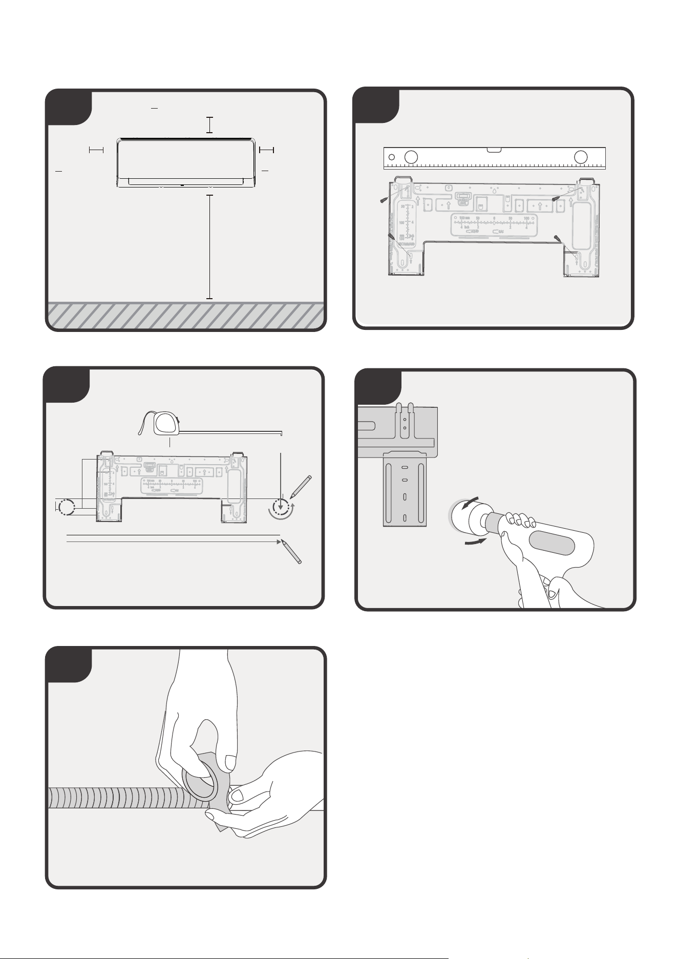
Installation Summary - Indoor Unit
Select Installation Location
Determine Wall Hole Position
Attach Mounting Plate
Drill Wall Hole
1
4
Prepare Drain Hose
5
>5.9in(15cm)
≥
>4.72in
(12cm)
>4.72in
(12cm)
70.87in(1.8m)
3
2
34
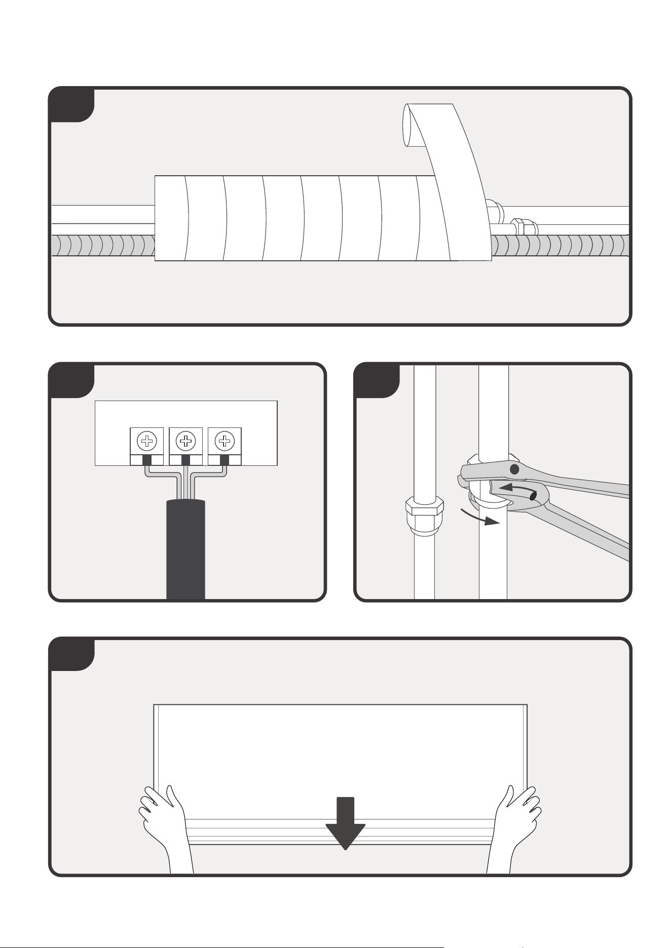
Installation Summary - Indoor Unit
Mount Indoor Unit
Connect Piping
8
Connect Wiring
7
Wrap Piping and drain hose
6
9
Before installing the indoor unit, refer to the label on the product box to make sure that the
model number of the indoor unit matches the model number of the outdoor unit.
Install Your Indoor Unit.
Select installation location
1
35
NOTE
: PRIOR TO INSTALLATION
The following are standards that will help you choose an appropriate location for the unit.
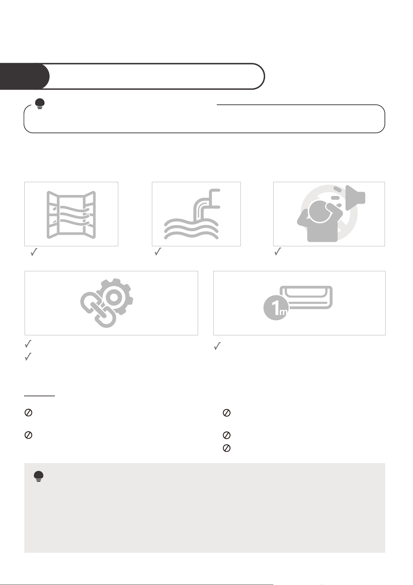
Proper installation locations meet the following standards:
Good air circulation
Convenient drainage
Noise from the unit will not
disturb other people.
Firm and solid—the location will not vibrate
Strong enough to support the weight of the
unit
A location at least one meter from all other
electrical devices (e.g., TV, radio, computer)
DO NOT
install unit in the following locations:
Near any source of heat, steam, or
combustible gas
Near flammable items such as curtains or
clothing
Near any obstacle that might block air
circulation
Near the doorway
In a location subject to direct sunlight
NOTE: FOR PRODUCT INSTALLATION
If there is no fixed refrigerant piping:
While choosing a location, be aware that you should leave ample room for a wall hole (see
Drill wall hole for connecting piping step) for the signal cable and refrigerant piping that
connect the indoor and outdoor units. The default position for all piping is the right side of
the indoor unit (while facing the unit). However, the unit can accommodate piping to both
the left and right.
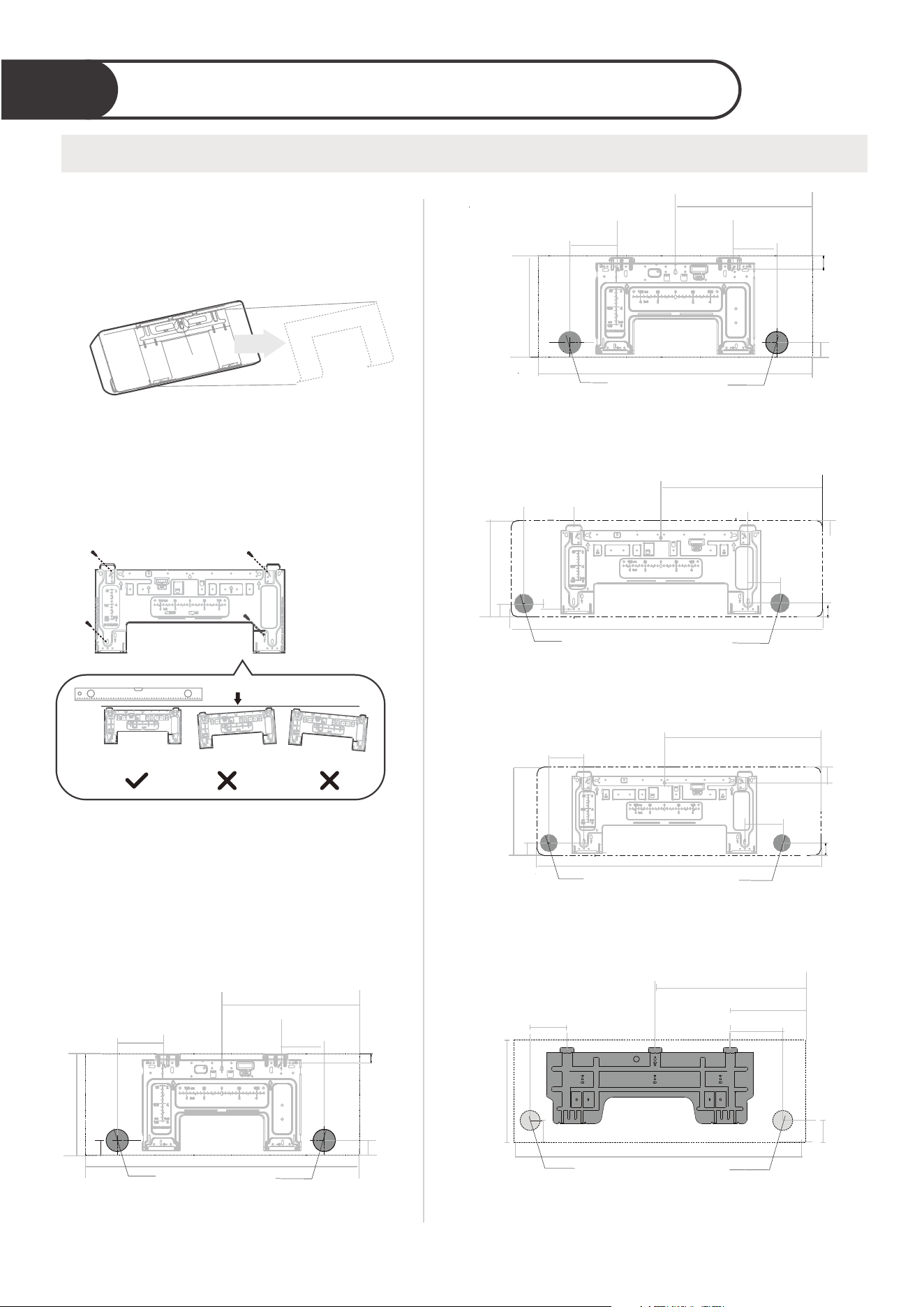
Determine wall hole location
Drill wall hole for connecting piping
2
36
Remove the screw that attaches the
mounting plate to the back of the
indoor unit.
Screw
Step 1:
20.43in(520mm)
3.74in(95mm)
1.1in(29mm)
1.62in
(41mm)
5.35in
(136mm)
W
W
15.9in(403mm)
H
H
1.77in(45mm)
1.77in(45mm)
1.46in
(37mm)
1.77in
(45mm)
1.77in
(45mm)
5.12in(130mm)
5.24in(133mm)
Indoor unit dimensions(WxH):
31.7in(806mm)x11.65in(296mm)
Indoor unit dimensions(WxH):
38.2in(971mm)x12.6in(321mm)
Φ2.5in(65mm)
Φ2.5in(65mm)
15.75in(400mm)
1.7in(45mm)
1.33in
(34mm)
1.77in
(45mm)
H
4.13in(105mm)
W
4.96in(126mm)
Indoor unit dimensions(WxH):
28.7in(729mm)x11.5in(293mm)
Φ2.5in(65mm)
22.8in(579mm)
3.8in(97mm)
2.7in
(70mm)
2.1in
(53mm)
2.1in
(53mm)
5.9in
(149mm)
W
H
Indoor unit dimensions(WxH):
42.6in(1082mm)x13.3(338mm)
Φ3.54in(90mm)
Correct orientation of Mounting Plate
Secure the mounting plate to the wall
with the screws provided. Make sure
that mounting plate is flat against
the wall.
Step 2:
Step 3:
Confirm the mounting plate you own.
Determine the location of the wall hole based
on the position of the mounting plate. The
dotted rectangular box on the right figure
shows the size of your product.
6.8in(172mm)
H
W
2.05in(52mm)
10.12in(257mm)
12.24in(311mm)
25.31in(643mm)
2.05in
(52mm)
Indoor unit dimensions(WxH):
49.57in(1259mm)x14.25in(362mm)
Φ3.54in(90mm )
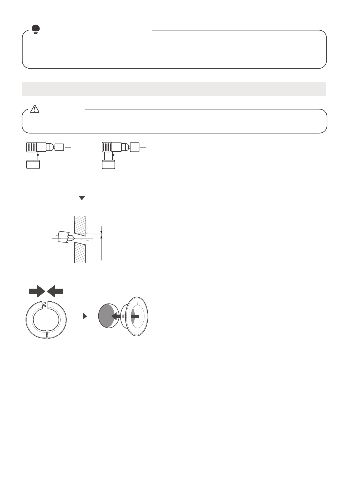
37
Drill wall hole
When drilling the wall hole, make sure to avoid wires, plumbing, and other sensitive
components.
CAUTION
The size of the wall hole is determined by the connecting pipes. When the pipe size
of the gas side is 5/8in( 16mm) or more, the wall hole should be 3.54in( 90mm).
When the pipe size of gas side is less than 5/8in( 16mm), the wall hole should be
2.5in( 65mm).
NOTE
: The wall hole size
Wall
Indoor
Outdoor
Fig.3.2
Drill the wall hole
Place the protective wall cu in the hole.
wall hole.
the protective
wall cu
Φ
Φ Φ
Φ
ΦΦ
Φ
Φ
If the wall is made of brick, concrete, or similar
material, drill 0.2in-diameter(5mm-diameter)
holes in the wall and insert the sleeve anchors
provided. Then secure the mounting plate to
the wall by tightening the screws directly into
the clip anchors.
NOTE:
FOR CONCRETE OR BRICK WALLS
Using a 2.5in(65mm) or 3.54in(90mm)
core drill, drill a hole in the wall. Make
sure that the hole is drilled at a slight
downward angle, so that the outdoor
end of the hole is lower than the indoor
end by about 0.2-0.275in(5-7mm).
This will ensure proper water drainage.
Place the protective wall cu in the hole.
This protects the edges of the hole and
will help seal it when you finish the
installation process.
Step 1:
Step 2:
0.2-0.275in
(5-7mm)
3.54in
(Φ 90mm)
2.5in
(Φ 65mm)
Using a 2.5in(65mm) or 3.54in(90mm)
core drill(according to the unit you purchased )
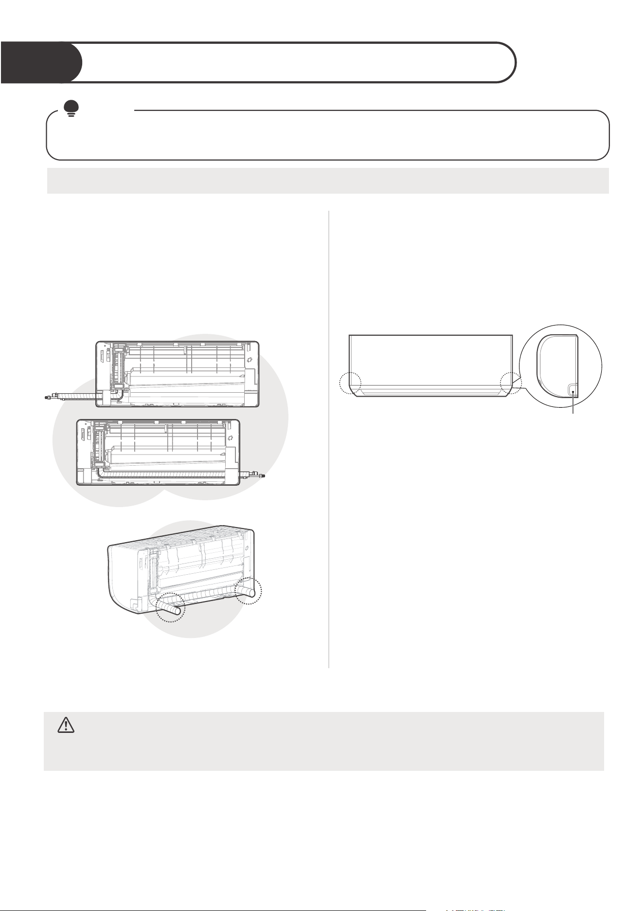
Install refrigerant pipe & drain hose
3
38
Prepare refrigerant piping
The refrigerant piping is inside an insulating sleeve attached to the back of the unit. You must prepare
the piping before passing it through the hole in the wall.
NOTE
Connect the indoor unit’s refrigerant piping to
the connective piping that will join the indoor
and outdoor units. Refer to the Refrigerant
Piping Connection section of this manual for
detailed instructions.
CAUTION
Be extremely careful not to dent or damage the piping while
bending them away from the unit. Any dents in the piping will
aect the unit’s performance.
Step 3:
If the wall hole is behind the unit, keep the
knock-out panel in place. If the wall hole is to
the side of the indoor unit, remove the plastic
knock-out panel from that side of the unit.Use
scissors or pliers if the plastic panel is too
dicult to remove by hand.
Knock-out
Panel
Knock-out Panel on
the left & right side
Step 2:
NOTE:If existing connective piping is
already embedded in the wall, proceed directly
to the Connect Drain Hose step.
Based on the position of the wall hole relative
to the mounting plate, choose the side from
which the piping will exit the unit(when you are
facing the back of the unit). You have four
options for the exit direction of the piping. The
description of the piping angle below for details.
Step 1:
Left-hand
side
Left rear
Right rear
Right-hand
side
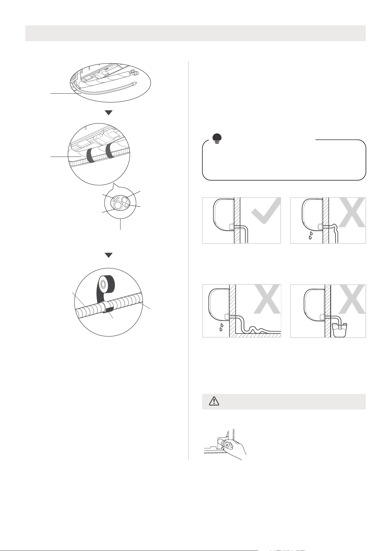
39
PLUG THE UNUSED DRAIN HOLE
To prevent unwanted leaks you
must plug the unused drain hole
with the rubber plug provided.
CORRECT
Make sure there are no
kinks or dent in drain hose
to ensure proper drainage.
NOT CORRECT
Kinks in the drain hose
will create water traps.
NOT CORRECT
Do not place the end of
the drain hose in water or
in containers that collect
water. This will prevent
proper drainage.
NOT CORRECT
Kinks in the drain hose
will create water traps.
CAUTION
For the portion of the drain hose that will
remain indoors, wrap it with foam pipe
insulation to prevent condensation.
Remove the air filter and pour a small amount
of water into the drain pan to make sure that
water flows from the unit smoothly.
●
●
The drain hose can be attached to the left
or right side. To ensure proper drainage,
attach the drain hose on the same side that
your refrigerant piping exits the unit. Attach
drain hose extension (purchased separately)
to the end of drain hose.
Wrap the connection point firmly with
Teflon tape to ensure a good seal and to
prevent leaks.
●
Step 1:
Make sure to arrange the drain hose
according to the following figures.
NOTE ON DRAIN
HOSE PLACEMENT
Connect drain hose
Drain
hose
Make sure the drain hose
is at the bottom
vinyl
tape
Connecting
cable
Gas side
piping
Liquid side
piping
Drain
hose
Vinyl tape(narrow)
Drain pipe
extension
Drain
pipe
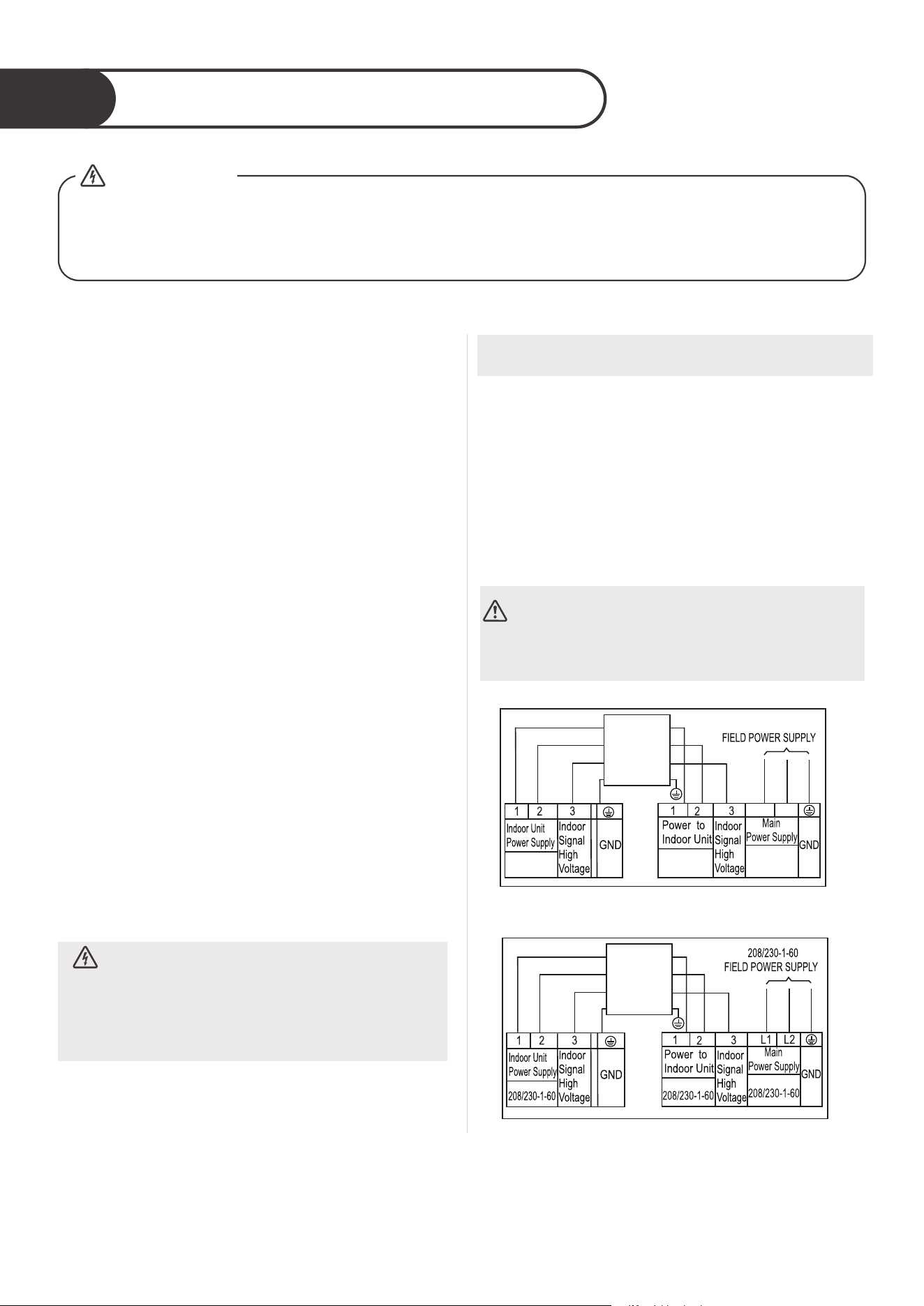
Electrical work preparation
4
40
1. All wiring must comply with local and national
electrical codes, regulations and must be
installed by a licensed electrician.
2. All electrical connections must be made
according to the Electrical Connection Diagram
located on the panels of the indoor and outdoor
units.
3. If there is a serious safety issue with the power
supply, stop work immediately. Explain your
reasoning to the client, and refuse to install the
unit until the safety issue is properly resolved.
4. If connecting power to fixed wiring, a surge
protector and main power switch should be
installed.
5. Only connect the unit to an individual branch
circuit outlet. Do not connect another appliance
to that outlet.
6. Make sure to properly ground the air conditioner.
7. Every wire must be firmly connected. Loose
wiring can cause the terminal to overheat,
resulting in product malfunction and possible fire.
8. Do not let wires touch or rest against refrigerant
tubing, the compressor, or any moving parts
within the unit.
9. To avoid getting an electric shock, never touch
the electrical components soon after the power
supply has been turned o. After turning o
the power, always wait 10 minutes or more
before you touch the electrical components.
Connect signal and power cables
The signal cable enables communication between
the indoor and outdoor units. You must first
choose the right cable size before preparing it for
connection.
NOTE: Choose the cable type according to the local
electrical codes and regulations. Please choose the
right cable size according to the Minimum Circuit
Ampacity indicated on the nameplate of the unit.
DO NOT MIX UP LIVE AND NULL WIRES
This is dangerous, and can cause the air
conditioning unit to malfunction.
BEFORE PERFORMING ANY ELECTRICAL WORK, READ THESE REGULATIONS
BEFORE PERFORMING ANY ELECTRLCAL OR WIRING WORK, TURN OFF
THE MAIN POWER TO THE SYSTEM.
●
●
WARNING
WARNING
All wiring must be performed strictly in
accordance with the wiring diagram
located on the back of the Indoor Unit’s
front panel.
CONNECTING
CABLE
OUTDOOR
TO INDOOR
CONNECTING
CABLE
OUTDOOR
TO INDOOR
115V-60Hz-1Ph
115V-60Hz-1Ph
L
N
115V-60Hz-1Ph115V-60Hz-1Ph
Connection Diagram (115V)
Connection Diagram (208/230V)
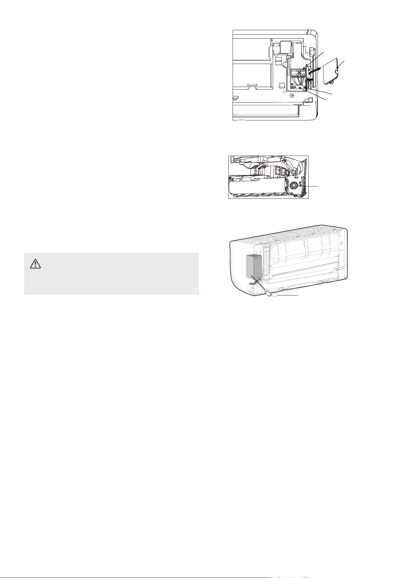
41
1. Open front panel of the indoor unit.
2. Using a screwdriver, open the wire box cover
on the right side of the unit. This will reveal
the terminal block.
3. Facing the back of the unit, remove the big plastic
konck-out panel to create a slot through which the
conduit tube can be installed.
NOTE:For the units with five-core cable, remove
the middle small plactic knock-out panel to create
a slot through which the cable can exit.
Use needle nose pliers if the plastic panel is too
dicult to remove by hand
4. As shown in the illustration, insert the wires
including the ground wire into the conduit
and secure them with lock nut onto the conduit
mounting plate.
5. Match wire colors with terminal numbers on indoor
and outdoor unit’s terminal blocks and firmly
screw wires to the corresponding terminals.
6. Connect the ground wires to the corresponding
terminals.
7. Pull the wires and check that the wires are
securely fixed to the terminal block.
DO NOT MIX UP LIVE AND NULL WIRES
This is dangerous, and can cause the air
conditioning unit to malfunction.
Conduit
Knock-out panel
Back view
Terminal block
Wire cover
Screw
Cable clamp
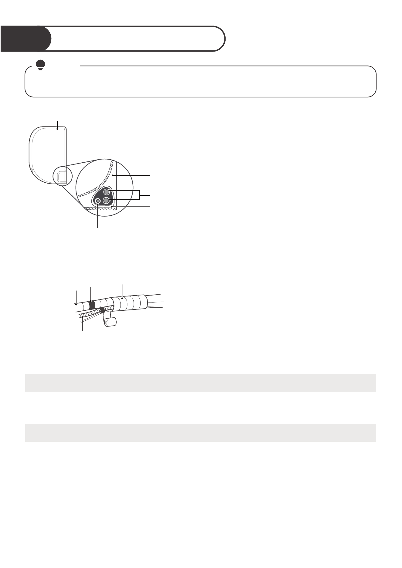
Wrap piping & Cables
5
DRAIN HOSE MUST BE ON BOTTOM
Make sure that the drain hose is at the bottom of the bundle. Putting the drain hose at the top of the bundle
can cause the drain pan to overflow, which can lead to fire or water damage.
When wrapping the bundle, keep the ends of the piping unwrapped. You need to access them to test for
leaks at the end of the installation process (refer to Electrical Checks and Leak Checks section of this
manual).
DO NOT WRAP ENDS OF PIPING
Bundle the drain hose, refrigerant pipes as
shown above.
Using insulation tape, wrap the refrigerant pipes,
and drain hose tightly together. Double-check that
all items are bundled.
Using adhesive vinyl tape, attach the drain hose to
the underside of the refrigerant pipes.
42
NOTE
Before passing the piping, and drain hose through the wall hole, you must bundle them together to
save space, protect them, and insulate them.
Space behind
unit
Indoor Unit
Refrigerant
piping
Drain hose
Insulation
tape
Step 1:
Step 2:
Step 3:
Drain hose
Vinyl tape
(narrow)
Pipe
Wrap with
insulation tape
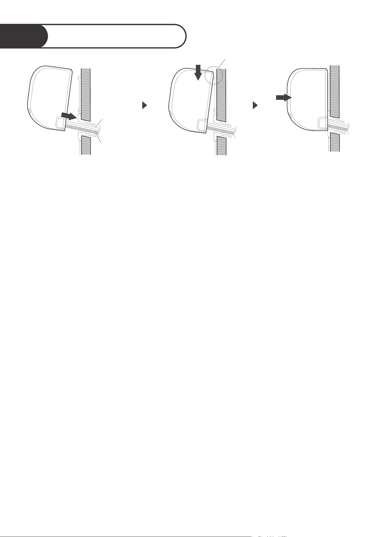
Mount indoor unit
6
43
If you have already passed the refrigerant piping through the hole in the wall, proceed to Step 4.
Otherwise, double-check that the ends of the refrigerant pipes are sealed to prevent dirt or foreign
materials from entering the pipes.
Slowly pass the wrapped bundle of refrigerant pipes, drain hose, and signal wire through the hole
in the wall.
Hook the top of the indoor unit on the upper hook of the mounting plate.
Check that unit is hooked firmly on mounting by applying slight pressure to the left and right-hand
sides of the unit. The unit should not jiggle or shift.
Using even pressure, push down on the bottom half of the unit. Keep pushing down until the unit
snaps onto the hooks along the bottom of the mounting plate.
Again, check that the unit is firmly mounted by applying slight pressure to the left and the right-hand
sides of the unit.
Put pipes in wall hole Hook it and press down
lightly to secure
Check that the unit is
firmly mounted
Drain
hose
Connecting
cable
Hook it
●
●
●
●
●
●
●
If you installed new connective piping to the outdoor unit, do the following:
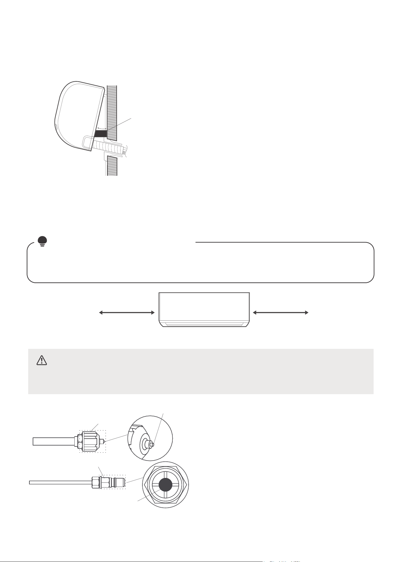
44
If refrigerant piping is already embedded in the wall,
do the following:
Hook the top of the indoor unit on the upper hook of the
mounting plate.
Use a bracket or wedge to prop up the unit, giving you
enough room to connect the refrigerant piping, signal cable,
and drain hose.
Connect drain hose and refrigerant piping (refer to
Refrigerant Piping Connection section of this manual for
instructions).
Keep pipe connection point exposed to perform the leak
test (refer to Electrical Checks and Leak Checks section of
this manual).
After the leak test, wrap the connection point with
insulation tape.
Remove the bracket or wedge that is propping up the unit.
Using even pressure, push down on the bottom half of the
unit. Keep pushing down until the unit snaps onto the hooks
along the bottom of the mounting plate.
Move to left or right
1.18-1.96in
(30-50mm)
1.18-1.96in
(30-50mm)
Wedge
30°
Keep in mind that the hooks on the mounting plate are smaller than the holes on the back of the unit.
If you find that you don’t have ample room to connect embedded pipes to the indoor unit, the unit
can be adjusted left or right by about 30-50mm (1.18-1.96in), depending on the model.
NOTE
: UNIT IS ADJUSTABLE
CAUTION
For the units adopt the following pipe connectors, please strictly perform the
piping work in accordance with the following instructions.
Connector A
Connector B
Cross-shape
part
Red point
protruding
Before performing the refrigerant piping
connection, always wear work gloves and
goggles, and remember that the connectors
A and B are not allowed to face people directly.
Keep pressing the cross-shape part of connector
B with a tool for about 5~10 seconds until the
red protuding point of connector A retracts
completely.
Remove connectors A and B, then perform
the refrigerant piping connection between
indoor unit and outdoor unit.
●
●
●
●
●
●
●
●
●
●
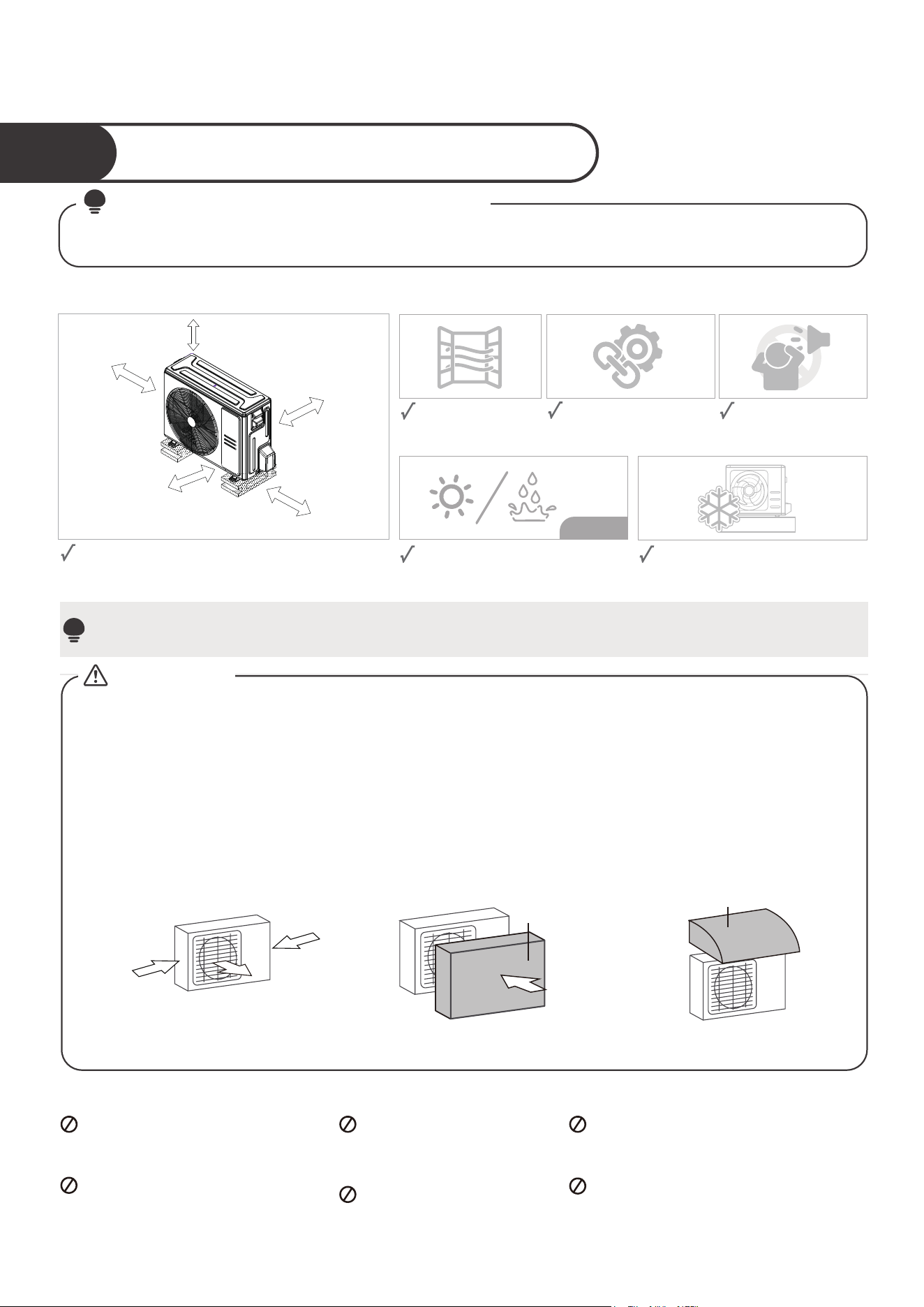
Install your Outdoor Unit.
45
Select installation location
1
Before installing the outdoor unit, you must choose an appropriate location. The following are
standards that will help you choose an appropriate location for the unit.
Proper installation locations meet the following standards:
Firm and solid—the
location can support the
unit and will not vibrate.
Protected from prolonged periods
of direct sunlight or rain.
Where snowfall is anticipated, take
appropriate measures to prevent
ice buildup and coil damage.
DO NOT install unit in the following locations:
Near an obstacle that will
block air inlets and outlets.
Near a public street, crowded
areas, or where noise from
the unit will disturb others.
Near animals or plants
that will be harmed
by hot air discharge.
Near any source of
combustible gas.
In a location that is exposed to large
amounts of dust
In a location exposed to a excessive
amounts of salty air.
NOTE
Install the unit by following local codes and regulations , there may be dier slightly between
dierent regions.
NOTE
: PRIOR TO INSTALLATION
Good air circulation
and ventilation.
Meets all spatial requirements shown in Installation
Space Requirements above.
Noise from the unit
will not disturb other
people.
Long-term
Strong
wind
Strong
wind
Strong
wind
Wind Baffle
If the unit is frequently exposed to heavy rain or snow:
Build a shelter above the unit to protect it from the rain or snow. Be careful not to obstruct air flow
around the unit.
If the unit is frequently exposed to salty air(seaside):
Use outdoor unit that is specially designed to resist corrosion.
90° angle to the
direction of the wind
Build a wind Bae
to protect the unit
Build a shelter
to protect the unit
If the unit is exposed to heavy wind:
Install unit so that air outlet fan is at a 90° angle to the direction of the wind. If needed, build a barrier
in front of the unit to protect it from extremely heavy winds. See Figures below.
CAUTION:
SPECIAL CONSIDERATIONS FOR EXTREME WEATHER
Shelter
4in.(100mm)
or more
20in.(500mm) or more when front
and sides of the unit are clear
14in.(350mm)
or more
4in.(100mm)
or more
20in.(500mm)
or more
when any 2
sides of left, right
and rear of the unit
are clear
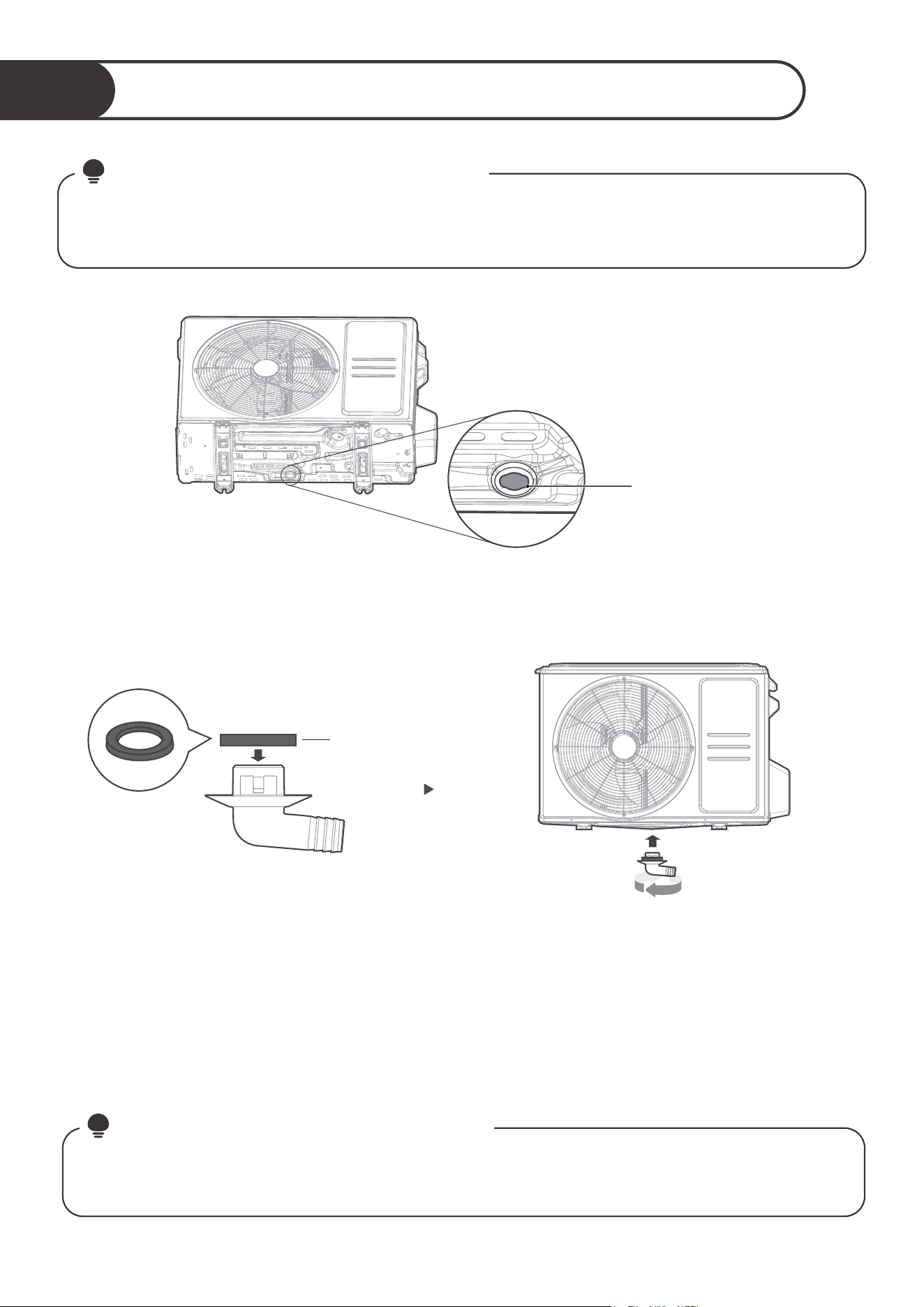
Install drain joint
2
46
Seal
In cold climates, make sure that the drain hose is as vertical as possible to ensure swift water drainage.
If water drains too slowly, it can freeze in the hose and flood the unit.
NOTE
: IN COLD CLIMATES
Base pan hole of
outdoor unit
Fit the rubber seal on the end of the drain joint that will connect to the
outdoor unit.
Insert the drain joint into the hole in the base pan of the unit. The drain joint
will click in place.
Connect a drain hose extension (not included) to the drain joint to redirect
water from the unit during heating mode.
●
●
●
Find out the base pan hole of outdoor unit.
Step 1:
Step 2:
Before bolting the outdoor unit in place, you must install the drain joint at the bottom of the unit.
For the units with base pan built-in with multiple holes for proper draining during defrost, the drain
joint is no need to be installed.
NOTE
: PRIOR TO INSTALLATION
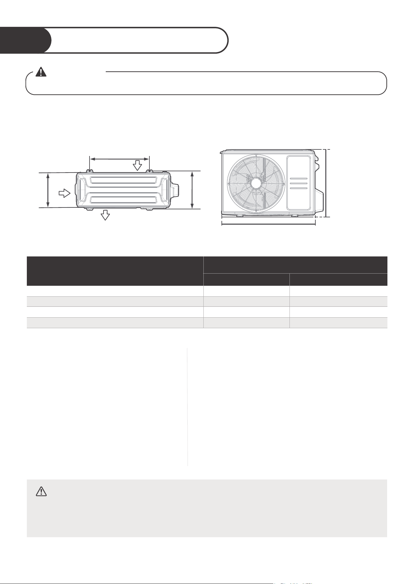
Anchor Outdoor Unit
3
The outdoor unit can be anchored to the ground or to a wall-mounted bracket with bolt(M10). Prepare
the installation base of the unit according to the dimensions below.
The following is a list of dierent outdoor unit sizes and the distance between their mounting feet.
Prepare the installation base of the unit according to the dimensions below.
W
H
Top view Front view
If you will install the unit on a wall-mounted
bracket , do the following:
Mark the position of bracket holes based on dimensions
chart.
Pre-drill the holes for the expansion bolts.
Place a washer and nut on the end of each expansion bolt.
Thread expansion bolts through holes in mounting
brackets, put mounting brackets in position, and hammer
expansion bolts into the wall.
Check that the mounting brackets are level.
Carefully lift unit and place its mounting feet on brackets.
Bolt the unit firmly to the brackets.
If allowed, install the unit with rubber gaskets to reduce
vibrations and noise.
If you will install the unit on the
ground or on a concrete mounting
platform, do the following:
Mark the positions for four expansion bolts
based on dimensions chart.
Pre-drill holes for expansion bolts.
Place a nut on the end of each expansion bolt.
Hammer expansion bolts into the pre-drilled
holes.
Remove the nuts from expansion bolts, and
place outdoor unit on bolts.
Put washer on each expansion bolt, the
replace the nuts.
Using a wrench, tighten each nut until snug.
47
D
A
B
Air inlet
Air inlet
Air outlet
WARNING
WHEN DRILLING INTO CONCRETE, EYE PROTECTION IS RECOMMENDED AT ALL TIME.
CAUTION
Make sure that the wall is made of solid brick, concrete, or of similarly strong
material.
The wall must be able to support at least four times the weight of the unit.
●
●
●
●
●
●
●
●
●
●
●
●
●
●
●
●
●
Outdoor Unit Dimensions
W x H x D
Mounting Dimensions
Distance A Distance B
30.1inx 21.8inx 11.9in(765mmx555mmx303mm )
17.8in(452mm)
11.3in(286mm)
26.1in(663mm)
26.5in(673mm)
13.9in(354mm)
15.9in(403mm)
37.2inx 31.9inx 16.1in(946mmx810mmx410mm)
31.7inx 21.8inx 12.9in(805mmx554mmx330mm)
20.1in(511mm) 12.5in(317mm)
35.0inx 26.5inx 13.5in(890mmx673mmx342mm)
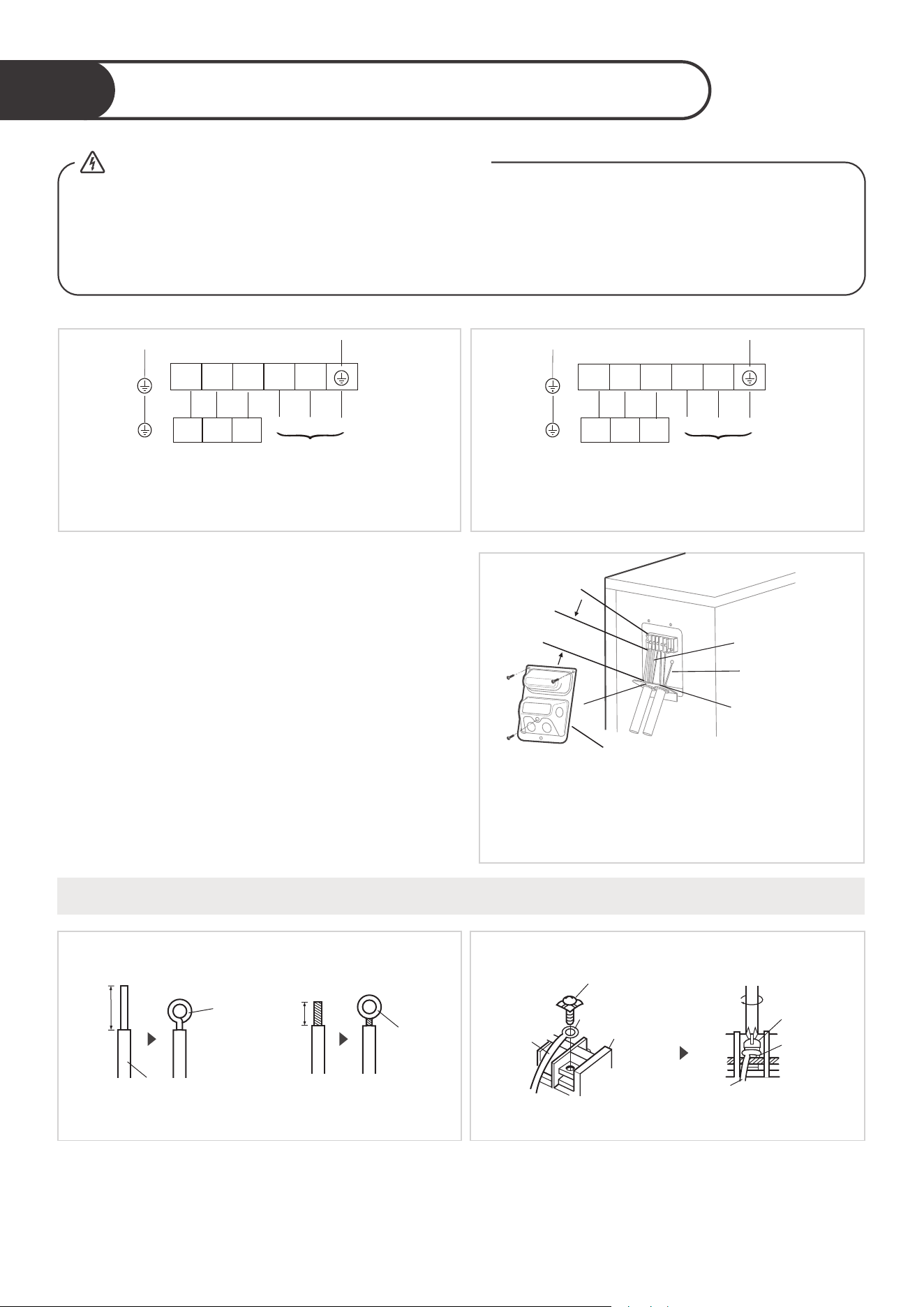
Connect signal and power cables
4
GG
Wire Cover
Over
1-9/16"
(40mm)
Terminal block
Conduit panel
Connecting cable
Power supply cord
Please select the appropriate through-hole according
to the diameter of the wire.
To indoor unit
1 2 3 L1 L2
Power supply
Y/G
To indoor unit
1 2 3 L N
Power supply
Y/G
48
Remove the wire cover from the unit by
loosening the 3 screws.
Dismount caps on the conduit panel.
Temperarily mount the conduit tubes(not
included) on the conduit panel.
Properly connect both the power supply and
low voltage lines to the corresponding
terminals on the terminal block.
Ground the unit in accordance with local codes.
Be sure to size each wire allowing several inches
longer than the required length for wiring.
Use lock nuts to secure the conduit tubes.
The outside unit’s terminal block is protected by
an electrical wiring cover on the side of the unit.
A comprehensive wiring diagram is printed on
the inside of the wiring cover.
Step 2:Step 1:
How to properly connect the wire lines.
Loop
Insulation
Strip 25mm(15/16")
Solid wire
Round
terminal
Strip 10mm(3/8")
Strand wire
Screw with
special
washer
Round terminal
Terminal plate
Wire
Screw with
special
washer
Wire
Round
terminal
The treatment about the end of the wire. connecting the line to the corresponding terminals
on the terminal block.
●
●
●
●
●
●
●
1 2 3
1 2 3
WARNING
ALL WIRING WORK MUST BE PERFORMED STRICTLY IN ACCORDANCE WITH
THE WIRING DIAGRAM LOCATED INSIDE OF WIRE COVER OF THE OUTDOOR
UNIT.
BEFORE PERFORMING ANY ELECTRICAL OR WIRING WORK,TURN OFF THE
MAIN POWER TO THE SYSTEM.
- Before the Operation
●
●
For 208/230V models
For 115V models
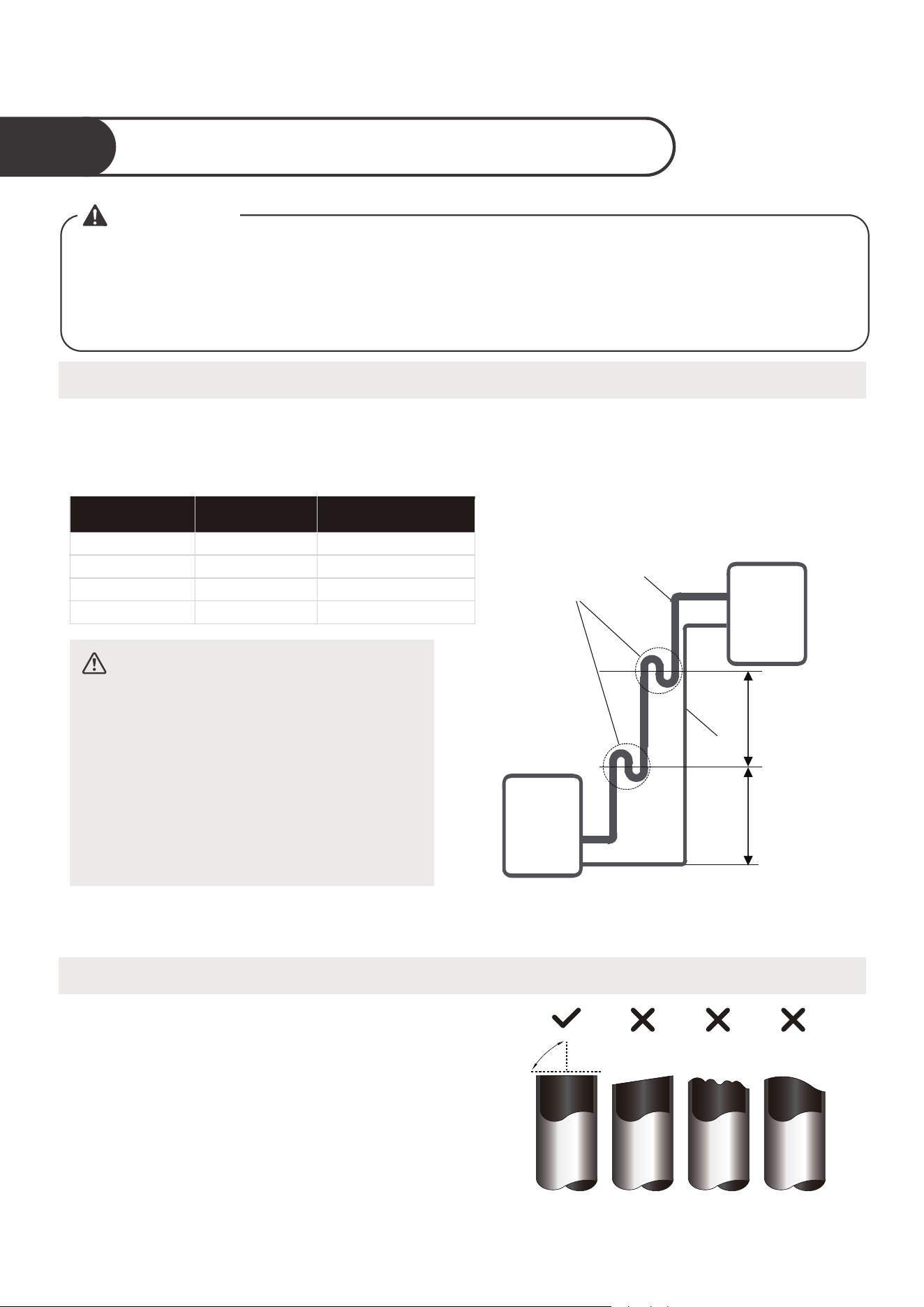
49
Piping Connection Precautions
Refrigerant Piping Connection
1
Note on Pipe Length
Connection Instructions – Refrigerant Piping
Step 1: Cut pipes
When preparing refrigerant pipes, take extra
care to cut and flare them properly. This will
ensure efficient operation and minimize the
need for future maintenance.
Measure the distance between the indoor
and outdoor units.
Using a pipe cutter, cut the pipe a little
longer than the measured distance.
Make sure that the pipe is cut at a perfect
90° angle.
Oblique Rough Warped
90°
The length of refrigerant piping will aect the performance and energy eciency of the unit. Nominal
eciency is tested on units with a pipe length of 25ft(7.5m). A minimum pipe run of 9.84ft(3m) is
required to minimise vibration & excessive noise. Connection Instructions – Refrigerant Piping.
●
●
●
WARNING
WHEN CONNECTING REFRIGERANT PIPING, DO NOT LET SUBSTANCES OR
GASES OTHER THAN THE SPECIFIED REFRIGERANT ENTER THE UNIT. THE
PRESENCE OF OTHER GASES OR SUBSTANCES WILL LOWER THE UNIT’S
CAPACITY, AND CAN CAUSE ABNORMALLY HIGH PRESSURE IN THE
REFRIGERATION CYCLE. THIS CAN CAUSE EXPLOSION AND INJURY.
The maximum length and drop height based on models.
Model
Length of piping
Maximum drop height
6K/9K/12K
18K
82ft/25m
98.4ft/30m
49.2ft/15m
65.6ft/20m
24K/30K/33K
164ft/50m
82ft/25m
36K
213ft/65m
98.4ft/30m
Oil trap
Liquid
piping
20ft/6m
(<36K)
32.8ft/10m
(≥36K)
20ft/6m
(<36K)
32.8ft/10m
(≥36K)
Gas piping
Indoor unit/
Outdoor unit
Indoor unit/
Outdoor unit
CAUTION
Oil traps
If oil flows back into the outdoor unit’s
compressor, this might cause liquid
compression or deterioration of oil return.
Oil traps in the rising gas piping can
prevent this.
An oil trap should be installed every
20ft(6m) of vertical suction line riser
(<36k). An oil trap should be
installed every 32.8ft(10m) of vertical
suction line riser (≥36k).
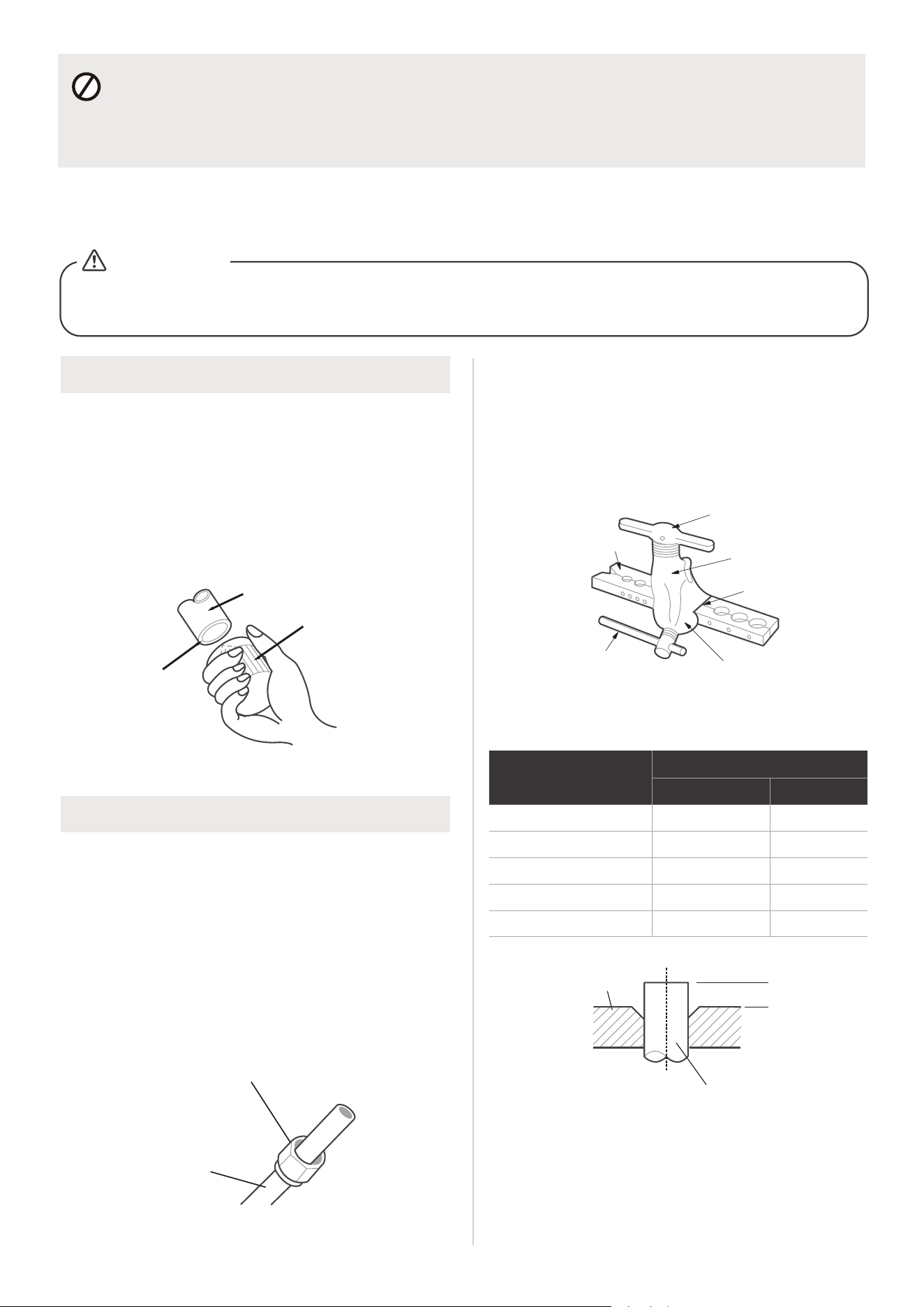
Step 2: Remove burrs
Burrs can aect the air-tight seal of refrigerant
piping connection. They must be completely
removed.
Pipe
Reamer
Point down
Step 3: Flare pipe ends
Proper flaring is essential to achieve an airtight
seal.
Flare nut
Copper pipe
PIPING EXTENSION BEYOND FLARE FORM
Flare form
Pipe
A
50
Hold the pipe at a downward angle to prevent
burrs from falling into the pipe.
Using a reamer or deburring tool, remove all
burrs from the cut section of the pipe.
After removing burrs from cut pipe, seal
the ends with PVC tape to prevent foreign
materials from entering the pipe.
Sheath the pipe with insulating material.
Place flare nuts on both ends of pipe. Make
sure they are facing in the right direction,
because you can’t put them on or change
their direction after flaring.
Remove PVC tape from ends of pipe when
ready to perform flaring work.
Clamp flare form on the end of the pipe.
The end of the pipe must extend beyond the
edge of the flare form in accordance with the
dimensions shown in the table below.
Place flaring tool onto the form.
Turn the handle of the flaring tool clockwise
until the pipe is fully flared.
Remove the flaring tool and flare form, then
inspect the end of the pipe for cracks and
even flaring.
MUST BE CHECK OVER THE END OF THE PIPE FOR CRACKS AND EVEN
FLARING. ENSURE THE PIPE IS SEALED.
CAUTION
Clamp handle
Red arrow mark
Cone
Yoke
Handle
Bar
●
●
●
●
●
●
●
●
●
●
DO NOT DEFORM PIPE WHILE CUTTING
Be extra careful not to damage, dent, or deform the pipe while cutting. This will drastically reduce
the heating eciency of the unit.
Max.
Outer Diameter of
Pipe
A
Min. Max.
Ø 1/4in (Ø 6.35mm)
0.0275in(0.7mm)
0.05in(1.3mm)
Ø 3/8in (Ø 9.52mm)
0.04in(1.0mm)
0.063in(1.6mm)
Ø1/2in (Ø 12.7mm)
0.04in(1.0mm)
0.07in(1.8mm)
Ø 5/8in (
Ø 16mm)
Ø 3/4in ( 19mm)Ø
0.078in(2.0mm)
0.086in(2.2mm)
0.078in(2.0mm)
0.094in(2.4mm)
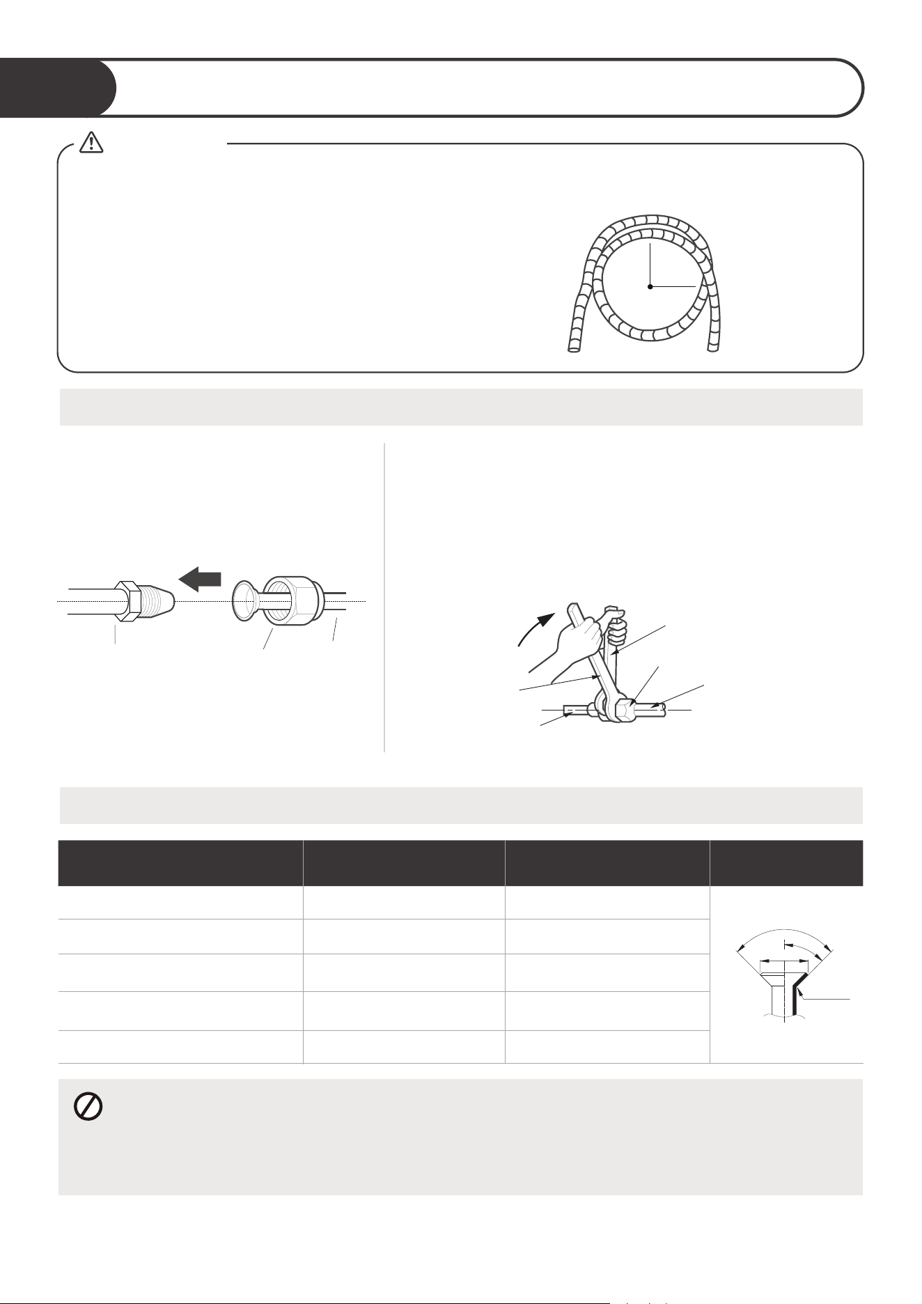
MINIMUM BEND RADIUS
When bending connective refrigerant piping,
the minimum bending radius is 10cm.
≥4in
(10cm)
Radius
Instructions for Connecting Piping to Indoor Unit
Align the center of the two pipes
that you will connect.
Tighten the flare nut as tightly as possible by hand.
Using a spanner, grip the nut on the unit tubing.
While firmly gripping the nut on the unit tubing, use a
torque wrench to tighten the flare nut according to the
torque values in the Torque Requirements table below.
Loosen the flaring nut slightly, then tighten again.
Refer to Torque Requirement to connect pipes
2
TORQUE REQUIREMENTS
DO NOT USE EXCESSIVE TORQUE
Excessive force can break the nut or damage the refrigerant piping. You must not exceed
torque requirements shown in the table above.
51
WHEN CONNECTING REFRIGERANT PIPES, BE CAREFUL NOT TO USE EXCESSIVE TORQUE OR
TO DEFORM THE PIPING IN ANY WAY. YOU SHOULD FIRST CONNECT THE LOW-PRESSURE PIPE,
THEN THE HIGH-PRESSURE PIPE.
CAUTION
Indoor unit tubing Flare nut Pipe
Torque
wrench
Indoor unit tubing
Spanner (fixed)
Connection pipe
Flare nut
Step 1: Step 2:
●
●
●
●
Outer Diameter of Pipe Tightening Torque
Flare dimension(B)
Flare shape
0.33~0.34in (8.4~8.7mm)
0.52~0.53in (13.2~13.5mm)
0.64~0.65in (16.2~16.5mm)
0.76~0.78in (19.2~19.7mm)
0.91~0.93in (23.2~23.7mm)
18~20N.m (180~200kgf.cm)
32~39N.m (320~390kgf.cm)
49~59N.m (490~590kgf.cm)
57~71N.m (570~710kgf.cm)
67~101N.m (670~1010kgf.cm)
R0.4~0.8
45
°
±
2
90
°
±
4
B
Ø 1/4in (Ø 6.35mm)
Ø 3/8in (Ø 9.52mm)
Ø1/2in (
Ø
12.7mm)
Ø 5/8in (
Ø 16mm)
Ø 3/4in (Ø 19mm)
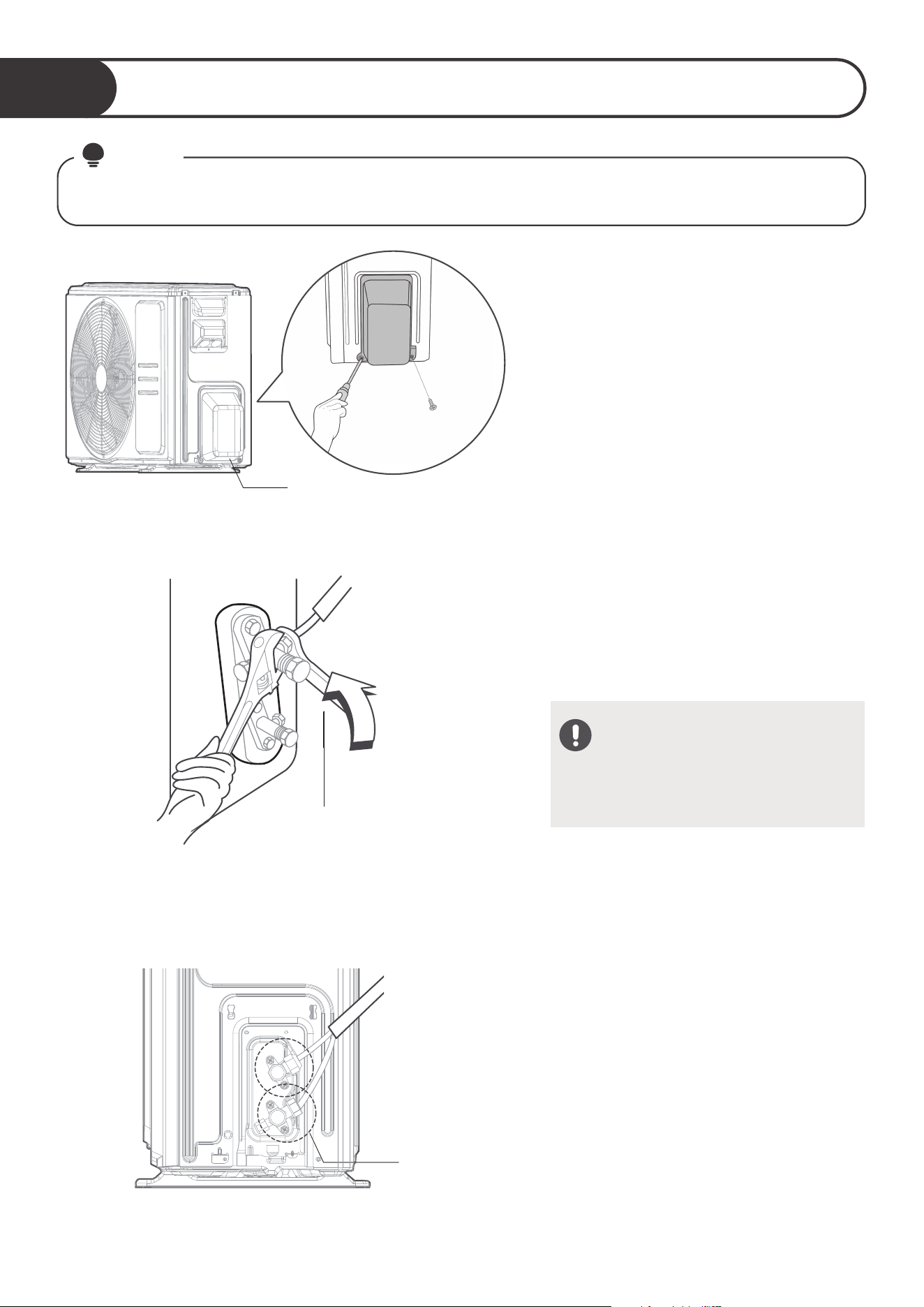
Outdoor unit
Liquid side piping
(Smaller diameter)
(Bigger
Torque wrench
52
Connecting Piping to Outdoor Unit
3
This section still needs to be operated according to the TORQUE REQUIREMENTS chart on the
previous page.
NOTE
Valve cover
Connect all
pipes
Unscrew
the cover
1. Unscrew the cover from the packed
valve on the side of the outdoor unit.
2. Remove protective caps from ends of
valves.
3. Align flared pipe end with each valve,
and tighten the flare nut as tightly as
possible by hand.
4. Using a spanner, grip the body of the
valve. Do not grip the nut that seals
the service valve.
5. While firmly gripping the body of the
valve, use a torque wrench to tighten
the flare nut according to the correct
torque values.
6. Loosen the flaring nut slightly, then
tighten again.
7. Repeat Steps 3 to 6 for the remaining
pipe.
USE SPANNER TO GRIP MAIN
BODY OF VALVE
Torque from tightening the flare nut
can snap o other parts of valve.
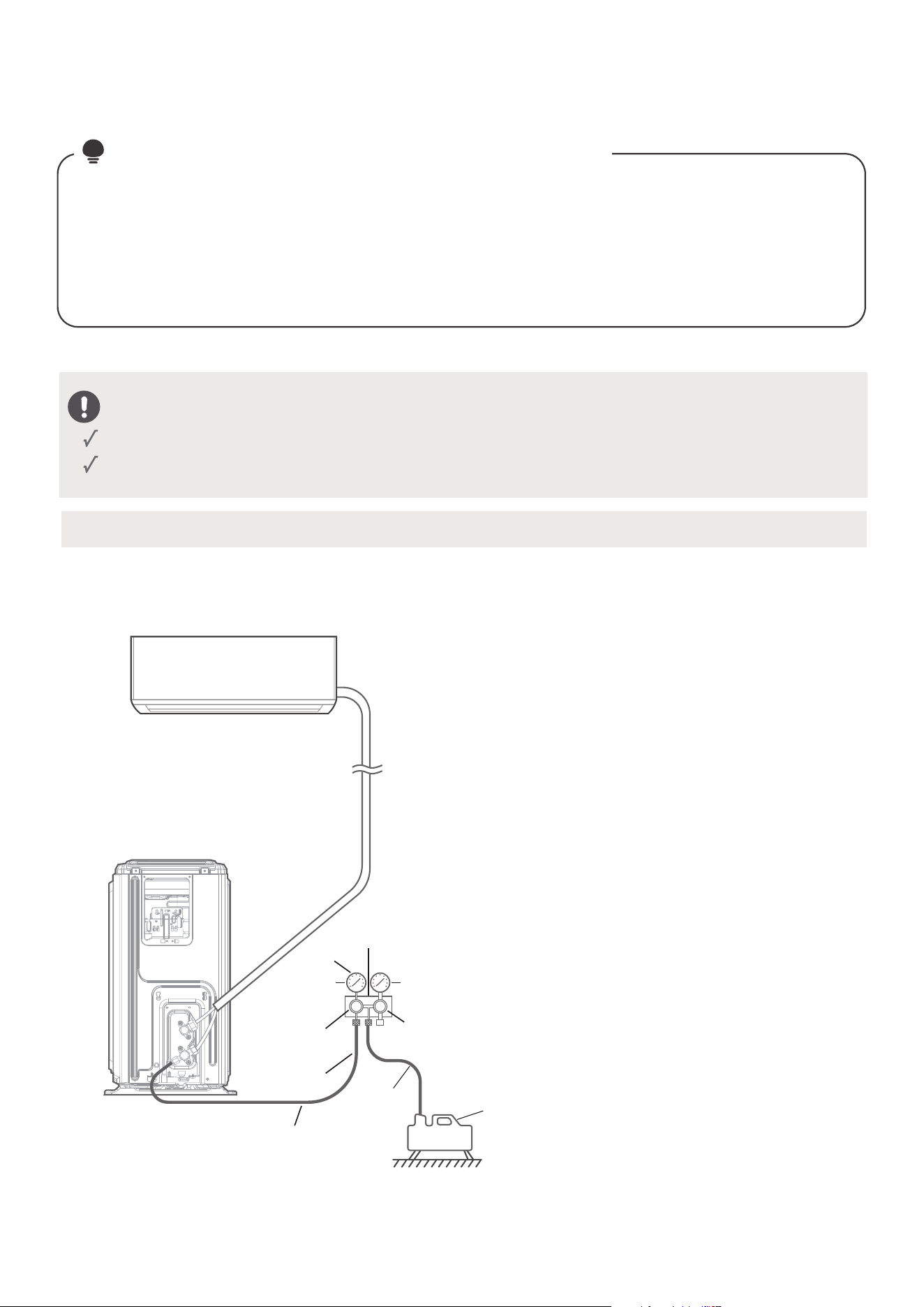
Outdoor unit
Indoor unit
Evacuation Instructions
Air Evacuation
53
NOTE
:
PREPARATIONS AND PRECAUTIONS
Air and foreign matter in the refrigerant circuit can cause abnormal rises in pressure, which can damage
the air conditioner, reduce its eciency, and cause injury. Ensure to evacuate the air inside the indoor
unit and pipes with vacuum pump. Use a vacuum pump and manifold gauge to evacuate the
refrigerant circuit, removing any non-condensable gas and moisture from the system. Evacuation
should be performed upon initial installation and when unit is relocated. Incorrect installation due to
ignoring of the Instruction will cause serious problem to the machine.
BEFORE PERFORMING EVACUATION
Make sure the connective pipes between the indoor and outdoor units are connected properly.
Check to make sure all wiring is connected properly.
Compound
gauge
-76cmHg
Low
pressure
valve
High
pressure
valve
Pressure hose
or
Charge hose
Vacuum
pump
Pressure
gauge
Low pressure
valve
Charge
hose
Manifold
valve
Connect the charge hose of the manifold
gauge to service port on the outdoor unit’s
low pressure valve.
Connect another charge hose from the
manifold gauge to the vacuum pump.
Open the Low Pressure side of the manifold
gauge. Keep the High Pressure side closed.
Turn on the vacuum pump to evacuate the
system.
Run the vacuum for at least 15 minutes, or
until the vacuum measured using micron
gauge to 500 microns. Close the Low
Pressure side of the manifold gauge, and
turn o the vacuum pump. Wait for 5
minutes, then check that there has been no
change in system pressure.
●
●
●
●
●
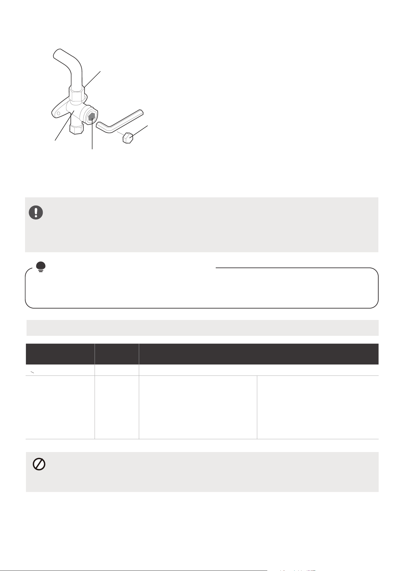
DO NOT MIX REFRIGERANT TYPES.
Make sure the additional amount of refrigerant to be charged is based on the pipe size and
length.
OPEN VALVE STEMS GENTLY
Ensure to open all the valves after evacuation. When opening valve stems, turn the hexagonal
wrench until it hits against the stopper. Do not try to force the valve to open further.
ADDITIONAL REFRIGERANT PER PIPE LENGTH
Connective Pipe
Length (m)
Air Purging
Method
Additional Refrigerant
< Standard pipe length Vacuum Pump N/A
> Standard pipe
length
Vacuum Pump
R454B:
R454B:
(Pipe length – standard length) x 15g/m
(Pipe length – standard length) x 0.16oz/ft
(Pipe length – standard length) x 30g/m
(Pipe length – standard length) x 0.32oz/ft
54
If there is a change in system pressure, refer to Gas Leak
Check section for information on how to check for leaks.
If there is no change in system pressure, unscrew the cap
from the packed valve (high pressure valve).
Insert hexagonal wrench into the packed valve(high
pressure valve) and open the valve by turning the wrench
in a 1/4 counterclockwise turn. Listen for gas to exit the
system, then close the valve after 5 seconds.
Watch the Pressure Gauge for one minute to make sure
that there is no change in pressure. The Pressure Gauge
should read slightly higher than atmospheric pressure.
Remove the charge hose from the service port.
Using hexagonal wrench, fully open both the high
pressure and low pressure valves.
Tighten valve caps on all three valves (service port, high
pressure, low pressure) by hand. You may tighten it
further using a torque wrench if needed.
NOTE
Some systems require additional charging depending on pipe lengths. The standard pipe length is
25ft(7.5m). The refrigerant should be charged from the service port on the outdoor unit’s low pressure
valve. The additional refrigerant to be charged can be calculated using the following formula:
ON ADDING REFRIGERANT
Flare nut
Cap
valve body
valve stem
●
●
●
●
●
●
Liquid Side: Ø 1/4in (Ø 6.35mm)
Liquid Side: Ø 3/8in(Ø 9.52mm)
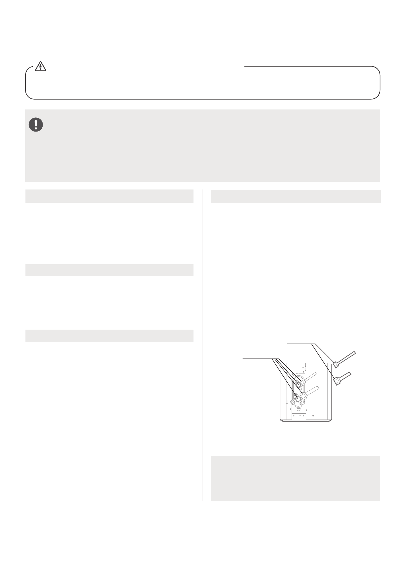
Electrical Safety Checks
After installation, confirm that all electrical wiring
is installed in accordance with local and national
regulations, and according to the Installation
Manual.
BEFORE TEST RUN
Check Grounding Work
Measure grounding resistance by visual detection
and with grounding resistance tester.
DURING TEST RUN
Check for Electrical Leakage
During the Test Run, use an electroprobe and
multimeter to perform a comprehensive electrical
leakage test.
If electrical leakage is detected, turn o the unit
immediately and call a licensed electrician to find
and resolve the cause of the leakage.
Note: This may not be required for some
locations in North America.
Gas Leak Checks
There are two dierent methods to check for gas
leaks.
Soap and Water Method
Using a soft brush, apply soapy water or liquid
detergent to all pipe connection points on the
indoor unit and outdoor unit. The presence of
bubbles indicates a leak.
Leak Detector Method
If using leak detector, refer to the device’s
operation manual for proper usage instructions.
AFTER PERFORMING GAS LEAK CHECKS
After confirming that the all pipe connection
points DO NOT leak, replace the valve cover on
the outside unit.
ALL WIRING MUST COMPLY WITH LOCAL AND NATIONAL ELECTRICAL
CODES, AND MUST BE NSTALLED BY A LICENSED ELECTRICIAN.
Electrical and Gas Leak Checks
55
WARNING
- RISK OF ELECTRIC SHOCK
BEFORE TEST RUN
Only perform test run after you have completed the following steps:
• Electrical Safety Checks – Confirm that the unit’s electrical system is safe and operating properly
• Gas Leak Checks – Check all flare nut connections and confirm that the system is not leaking
• Confirm that gas and liquid (high and low pressure) valves are fully open
A: Low pressure stop valve
B: High pressure stop valve
C& D: Indoor unit flare nuts
Check-point of
indoor unit
Check-point of
outdoor unit
A
B
C
D
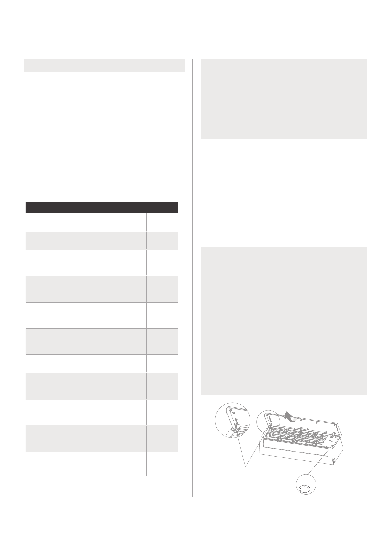
Test Run Instructions
You should perform the Test Run for at least 30
minutes.
Connect power to the unit.
Press the ON/OFF button on the remote
controller to turn it on.
Press the MODE button to scroll through the
following functions, one at a time:
• COOL–Select lowest possible temperature
• HEAT–Select highest possible temperature
Let each function run for 5 minutes, and
perform the following checks:
List of Checks to Perform PASS/FAIL
No electrical leakage
Unit is properly grounded
All electrical terminals
properly covered
Indoor and outdoor units
are solidly installed
All pipe connection
points do not leak
Outdoor
(2):
Indoor
(2):
Water drains properly
from drain hose
All piping is properly
insulated
Unit performs COOL
function properly
Unit performs HEAT
function properly
Indoor unit louvers
rotate properly
Indoor unit responds to
remote controller
DOUBLE-CHECK PIPE CONNECTIONS
During operation, the pressure of the
refrigerant circuit will increase. This may
reveal leaks that were not present during your
initial leak check. Take time during the Test
Run to double-check that all refrigerant pipe
connection points do not have leaks. Refer to
Gas Leak Check section for instructions.
After the Test Run is successfully completed,
and you confirm that all checks points in List
of Checks to Perform have PASSED, do the
following:
a. Using remote control, return unit to
normal operating temperature.
b. Using insulation tape, wrap the indoor
refrigerant pipe connections that you
left uncovered during the indoor unit
installation process.
Test Run
56
●
●
●
●
●
IF AMBIENT TEMPERATURE IS
BELOW 16°C(60°F)
You can not use the remote controller to turn
on the COOL function when the ambient
temperature is below 60°F. In this instance,
you can use the MANUAL CONTROL button
to test the COOL function.
Lift the front panel of the indoor unit.
Note: If there is a supporting rod located
on the left or right side. Please use it to prop
up the panel.
The MANUAL CONTROL button is located
on the right-hand side of the unit. Press two
times to select FORCED COOL mode.
Perform Test Run as normal.
●
●
●
Manual
control
button
Supporting rod
(located on the
left or right,
model dependent )
AUTO/COOL

Instructions for packing and unpacking the unit:
Unpacking:
Indoor unit:
1. Cut the sealing tape on the carton with a knife, one cut on the left, one cut in the middle and one
cut on the right.
2.Use the vice to take out the sealing nails on the top of the carton.
3.Open the carton.
4.Take out the middle support plate if it is included.
5.Take out the accessory package, and take out the connecting wire if it is included.
6.Lift the machine out of the carton and lay it flat.
7.Remove the left and right package foam or the upper and lower packaging foam, untie the
packaging bag.
Outdoor Unit
1.Cut the packing belt.
2.Take the unit out of the carton.
3.Remove the foam from the unit.
4.Remove the packaging bag from the unit.
Packing:
Indoor unit:
1.Put the indoor unit into the packing bag.
2.Attach the left and right package foam or the upper and lower packaging foam to the unit.
3.Put the unit into the carton, then put accessory package in.
4.Close the carton and seal it with the tape.
5.Using the packing belt if necessary.
Outdoor unit:
1.Put the outdoor unit into the packing bag.
2.Put the bottom foam into the box.
3.Put the unit into the carton, then put the upper packaging foam on the unit.
4.Close the carton and seal it with the tape.
5.Using the packing belt if necessary.
NOTE:
Please keep all packaging items if you may need in the future.
Packing and Unpacking The Unit
57


The design and specifications are subject to change without prior notice for
product improvement. Consult with the sales agency or manufacturer for details.
Any updates to the manual will be uploaded to the service website, please check
for the latest version.
CS020UI-AG(R454B)
16122600A08852
7 5/01/2022