Owner’s Manual &
Installation Manual
MHMZ Series
INVERTER ONE-TWO/ONE-THREE/ONE-FOUR/ONE-FIVE
SPLIT-TYPE AIR CONDITIONER
IMPORTANT NOTE:
Read this manual carefully before installing
or operating your new air conditioning
unit. Make sure to save this manual for
future reference.
Please check the applicable models, technical
data, F-GAS(if any) and manufacturer information
from the “Owner's Manual - Product Fiche ”
in the packaging of the outdoor unit.
(European Union products only)

Owner’s Manual
Table of Contents
Safety Precautions
Unit Parts And Major Functions
1. Unit Parts
2. Operating temperature
3. Features
Manual Operations And Maintenance
Troubleshooting
........................................................................04
...................................................08
.............................................................................................................................................................................08
..................................................................................................................................................10
...............................................................................................................................................................................11
..........................................13
............................................................................14

Installation Manual
Accessories
Installation Summary
Installation Diagram
Specifications
Outdoor Unit Installation
1. Select installation location
2. Install drain joint
3. Anchor outdoor unit
Refrigerant Piping Connection
1. Cut pipe
2. Remove burrs
3. Flare pipe ends
4. Connect pipes
Wiring
1. Outdoor Uint Wiring
2. Wiring Figure
Air Evacuation
1. Note On Adding Refrigerant
2. Safety And Leakage Check
Test Run
Function of Automatic Wiring/Piping Correction
.......................................................................................17
.........................................................................18
...........................................................................19
.....................................................................................20
...................................................................21
....................................................................................................................................................21
.......................................................................................................................................................................22
................................................................................................................................................................22
.........................................................24
........................................................................................................................................................................................24
...........................................................................................................................................................................24
..........................................................................................................................................................................24
............................................................................................................................................................................25
.................................................................................................27
.................................................................................................................................................................29
..............................................................................................................................................................................30
...................................................................................37
.................................................................................................................................................38
....................................................................................................................................................40
..............................................................................................41
.............................42
IntroductionPrecautions
Read Safety Precautions Before Operation and Installation
The seriousness of potential damage or injuries is classified as either a WARNING or CAUTION.
Incorrect installation due to ignoring instructions can cause serious damage or injury.
WARNING
This appliance can be used by children aged from 8 years and above and persons with reduced
This appliance is not intended for use by persons(including children) with reduced physical, sensory
or mental capabilities, or lack of experience and knowledge, unless they have been given supervision
or instruction concerning use of the appliance by a person responsible for their safety. Children
should be supervised to ensure that they do not play with the appliance.
physical, sensory or mental capabilities or lack of experience and knowledge if they have been given
supervision or instruction concerning use of the appliance in a safe way and understand the hazards
involved. Children shall not play with the appliance. Cleaning and user maintenance shall not be
made by children without supervision.
WARNINGS FOR PRODUCT USE
•
If an abnormal situation arises (like a burning smell), immediately turn o the unit and disconnect
the power. Call your dealer for instructions to avoid electric shock, re or injury.
•
Do not
insert fingers, rods or other objects into the air inlet or outlet. This may cause injury, since
the fan may be rotating at high speeds.
•
Do not
use flammable sprays such as hair spray, lacquer or paint near the unit. This may cause
fire or combustion.
•
Do not
operate the air conditioner in places near or around combustible gases. Emitted gas may
collect around the unit and cause explosion.
•
Do not
•
•
Do not
expose your body directly to cool air for a prolonged period of time.
•
•
If the air conditioner is used together with burners or other heating devices, thoroughly ventilate
the room to avoid oxygen deficiency.
Safety Precautions
Do not
allow children to play with the air conditioner. Children must be supervised around the
unit at all times.
operate your air conditioner in a wet room such as a bathroom or laundry room. Too
much exposure to water can cause electrical components to short circuit.
In certain functional environments, such as kitchens, server rooms, etc., the use of specially
designed air-conditioning units is highly recommended.
CLEANING AND MAINTENANCE WARNINGS
•
Turn o the device and disconnect the power before cleaning. Failure to do so can cause
electrical shock.
•
Do not
clean the air conditioner with excessive amounts of water.
WARNING
This symbol indicates the possibility
of personnel injury or loss of life.
CAUTION
This symbol indicates the possibility of
property damage or serious consequences.
Safety
Precautions
e f
•
Do not
clean the air conditioner with combustible cleaning agents. Combustible cleaning agents
can cause re or deformation.
CLEANING AND MAINTENANCE WARNINGS
CAUTION
•
Turn o the air conditioner and disconnect the power if you are not going to use it for a long time.
•
Turn o and unplug the unit during storms.
•
Make sure that water condensation can drain unhindered from the unit.
• Do not
operate the air conditioner with wet hands. This may cause electric shock.
• Do not
use device for any other purpose than its intended use.
• Do not
climb onto or place objects on top of the outdoor unit.
• Do not
allow the air conditioner to operate for long periods of time with doors or windows open,
or if the humidity is very high.
ELECTRICAL WARNINGS
•
Only use the specified power cord. If the power cord is damaged, it must be replaced by the
manufacturer
, its service agent or similarly qualied persons in order to avoid a hazard.
•
Keep power plug clean. Remove any dust or grime that accumulates on or around the plug. Dirty
plugs can cause re or electric shock.
•
•
•
•
•
•
•
Do not
pull power cord to unplug unit. Hold the plug firmly and pull it from the outlet. Pulling
directly on the cord can damage it, which can lead to fire or electric shock.
Do not
modify the length of the power supply cord or use an extension cord to power the unit.
Do not
share the electrical outlet with other appliances. Improper or insucient power supply
can cause re or electrical shock.
If connecting power to xed wiring, an all-pole disconnection device which has at least 3mm
clearances in all poles, and have a leakage current that may exceed 10mA, the residual current
device(RCD) having a rated residual operating current not exceeding 30mA, and disconnection
must be incorporated in the xed wiring in accordance with the wiring rules.
For all electrical work, follow all local and national wiring standards, regulations, and the
Installation Manual. Connect cables tightly
, and clamp them securely to prevent external for
ces
fr
om damaging the terminal. Improper electrical connections can overheat and cause r
e, and may
also cause shock.
All electrical connections must be made according to the Electrical Connection
Diagram located on the panels of the indoor and outdoor units.
All wiring must be properly arranged to ensure that the control board cover can close properly. If
the contr
ol board cover is not closed properly, it can lead to corrosion and cause the connection
points on the terminal to heat up, catch r
e, or cause electrical shock.
The product must be properly grounded at the time of installation, or electrical shock may occur.
TAKE NOTE OF FUSE SPECIFICATIONS
The air conditioner’s circuit board (PCB) is designed with a fuse to provide overcurrent protection.
The specifications of the fuse are printed on the circuit board ,such as :
T20A/250VAC(for <24000Btu/h unit), T30A/250VAC(for >24000Btu/h unit)
NOTE: For the units with R32 or R290 refrigerant , only the blast-proof ceramic fuse can be used.
WARNINGS FOR PRODUCT INSTALLATION
1.
Installation must be performed by an authorized dealer or specialist. Defective installation can
cause water leakage, electrical shock, or re.
Safety
Precautions
ef
WARNINGS FOR PRODUCT INSTALLATION
2.
Installation must be performed according to the installation instructions. Improper installation
can cause water leakage, electrical shock, or re.
(In North America,installation must be performed in accordance with the requirement of NEC
and CEC by authorized personnel only.)
3.
Contact an authorized service technician for repair or maintenance of this unit. This appliance
shall be installed in accordance with national wiring regulations.
4.
Only use the included accessories, parts, and specied parts for installation. Using non-standard
parts can cause water leakage, electrical shock, re, and can cause the unit to fail.
5.
6.
Install the unit in a rm location that can support the unit’s weight. If the chosen location cannot
support the unit’s weight, or the installation is not done properly, the unit may drop and cause
serious injury and damage.
7.
8.
9.
10.
11.
Do not turn on the power until all work has been completed.
When moving or relocating the air conditioner, consult experienced service technicians for
disconnection and reinstallation of the unit.
How to install the appliance to its support, please read the information for details in "indoor unit
installation" and "outdoor unit installation" sections .
For units that have an auxiliary electric heater, do not install the unit within 1 meter (3 feet) of
any combustible materials.
Do not
install the unit in a location that may be exposed to combustible gas leaks. If
combustible
gas accumulates around the unit, it may cause re.
Install drainage piping according to the instructions in this manual. Improper drainage may
cause water damage to your home and property.
Note about Fluorinated Gasses(Not applicable to the unit using R290 Refrigerant)
1.
This air-conditioning unit contains fluorinated greenhouse gasses. For specic information on the
type of gas and the amount, please refer to the relevant label on the unit itself or
the
“Owner's Manual - Product Fiche ” in the packaging of the outdoor unit.
(European
Union products only)
.
2.
Installation, service, maintenance and repair of this unit must be performed by a certified
technician.
3.
Product uninstallation and recycling must be performed by a certified technician.
4.
For equipment that contains uorinated greenhouse gases in quantities of 5 tonnes of CO
2
equivalent or more, but of less than 50 tonnes of CO
2
equivalent, If the system has a leak-
detection system installed, it must be checked for leaks at least every 24 months.
5.
When the unit is checked for leaks, proper record-keeping of all checks is strongly recommended.
WARNING for Using R32 Refrigerant
When ammable refrigerant are employed, appliance shall be stored in a well -ventilated area
where the room size corresponds to the room area as speciec for operation.
For R32 frigerant models:
Appliance shall be installed, operated and stored in a room with a oor area larger than
X m²
.
Appliance shall not be installed in an unvertilated space, if that space is smaller than
X m²
.
(Please see the following form).
Safety
Precautions
ef
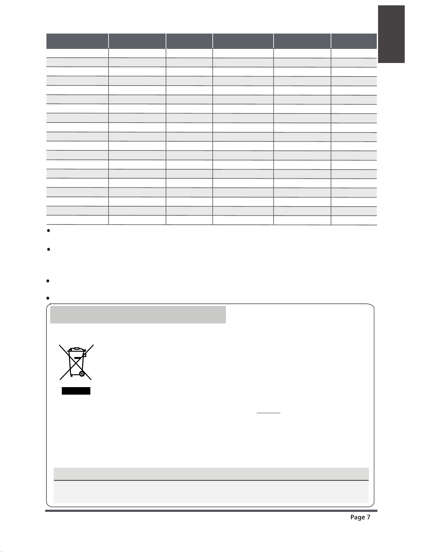
European Disposal Guidelines
This appliance contains refrigerant and other potentially hazardous materials. When disposing of
this appliance, the law requires special collection and treatment. Do not dispose of this product as
household waste or unsorted municipal waste.
When disposing of this appliance, you have the following options:
• Dispose
of
the
appliance
at
designated
municipal
electronic
waste
collection
facility.
• When buying a new appliance, the retailer will take back the old appliance free of charge.
• The manufacturer will take back the old appliance free of charge.
• Sell the appliance to certied scrap metal dealers.
Special notice
Disposing of this appliance in the forest or other natural surroundings endangers your health and is bad
for the environment. Hazardous substances may leak into the ground water and enter the food chain.
CorrectDisposal ofThis Product
(Waste Electrical &Electronic Equipment)
This marking shown on the product or its literature, indicates that waste electrical and
eletrical equipment should not be mixed with general household waste.
Reusable mechanical connectors and ared joints are not allowed indoors.
(EN Standard Requirements).
Mechanical connectors used indoors shall have a rate of not more than 3g/year at 25% of the
maximum allowable pressure. When mechanical connectors are reused indoors, sealing parts shall
be renewed. When ared joints are reused indoors, the are part shall be re-fabricated.
(UL Standard Requirements)
When mechanical connectors are reused indoors, sealing parts shall be renewed. When ared
joints are reused indoors, the are part shall be re-fabricated. (IEC Standard Requirements)
Mechanical connectors used indoors shall comply with ISO 14903.
Safety
Precautions
ef
Amount of refrigerant
to be charged (kg)
Installation height
(m)
Installation height
(m)
Minimum room
area (m²)
Amount of refrigerant
to be charged (kg)
Minimum room
area (m²)
1.0 0.6 /1.8 /2.2 9 /1 /1
1.05 0.6 /1.8 /2.2 9.5 /1.5 /1
1.1 0.6 /1.8 /2.2 10.5 /1.5 /1
1.15 0.6 /1.8 /2.2 11.5 /1.5 /1
1.2 0.6 /1.8 /2.2 12.5 /1.5 /1
1.25 0.6 /1.8 /2.2 13.5 /1.5 /1
1.3 0.6 /1.8 /2.2 14.5 /2 /1.5
1.35 0.6 /1.8 /2.2 16 /2 /1.5
1.4 0.6 /1.8 /2.2 17/2 /1.5
1.45 0.6 /1.8 /2.2 18 /2 /1.5
1.5 0.6 /1.8 /2.2 19.5 /2.5 /1.5
1.55 0.6 /1.8 /2.2 21 /2.5 /2
1.6 0.6 /1.8 /2.2 22 /2.5 /2
1.65 0.6 /1.8 /2.2 23.5 /3 /2
1.7 0.6 /1.8 /2.2 25 /3 /2
1.75 0.6 /1.8 /2.2 26.5 /3 /2
1.8 0.6 /1.8 /2.2 28 /3.5 /2.5
1.85 0.6 /1.8 /2.2 29.5 /3.5 /2.5
1.9 0.6 /1.8 /2.2 31/3.5 /2.5
1.95 0.6 /1.8 /2.2 33 /4 /2.5
2.0 0.6 /1.8 /2.2 34.5 /4 /3
2.05 0.6 /1.8 /2.2 36 /4 /3
2.1 0.6 /1.8 /2.2 38 /4.5 /3
2.15 0.6 /1.8 /2.2 40 /4.5 /3
2.2 0.6 /1.8 /2.2 41.5 /5 /3.5
2.25 0.6 /1.8 /2.2 43.5 /5 /3.5
2.3 0.6 /1.8 /2.2 45.5/5 /3.5
2.35 0.6 /1.8 /2.2 47.5/5.5 /4
2.4 0.6 /1.8 /2.2 49.5 /5.5 /4
2.45 0.6 /1.8 /2.2 51.5 /6 /4
2.5 0.6 /1.8 /2.2 54 /6 /4
2.55 0.6 /1.8 /2.2 56 /6.5 /4.5
2.6 0.6 /1.8 /2.2 58 /6.5 /4.5
2.65 0.6 /1.8 /2.2 60.5/7 /4.5
2.7 0.6 /1.8 /2.2 63 /7 /5
2.75 0.6 /1.8 /2.2 65 /7.5 /5
2.8 0.6 /1.8 /2.2 67.5 /7.5 /5
2.85 0.6 /1.8 /2.2 70 /8 /5.5
Unit Parts
And Major
Functions
Unit Parts And Major Functions
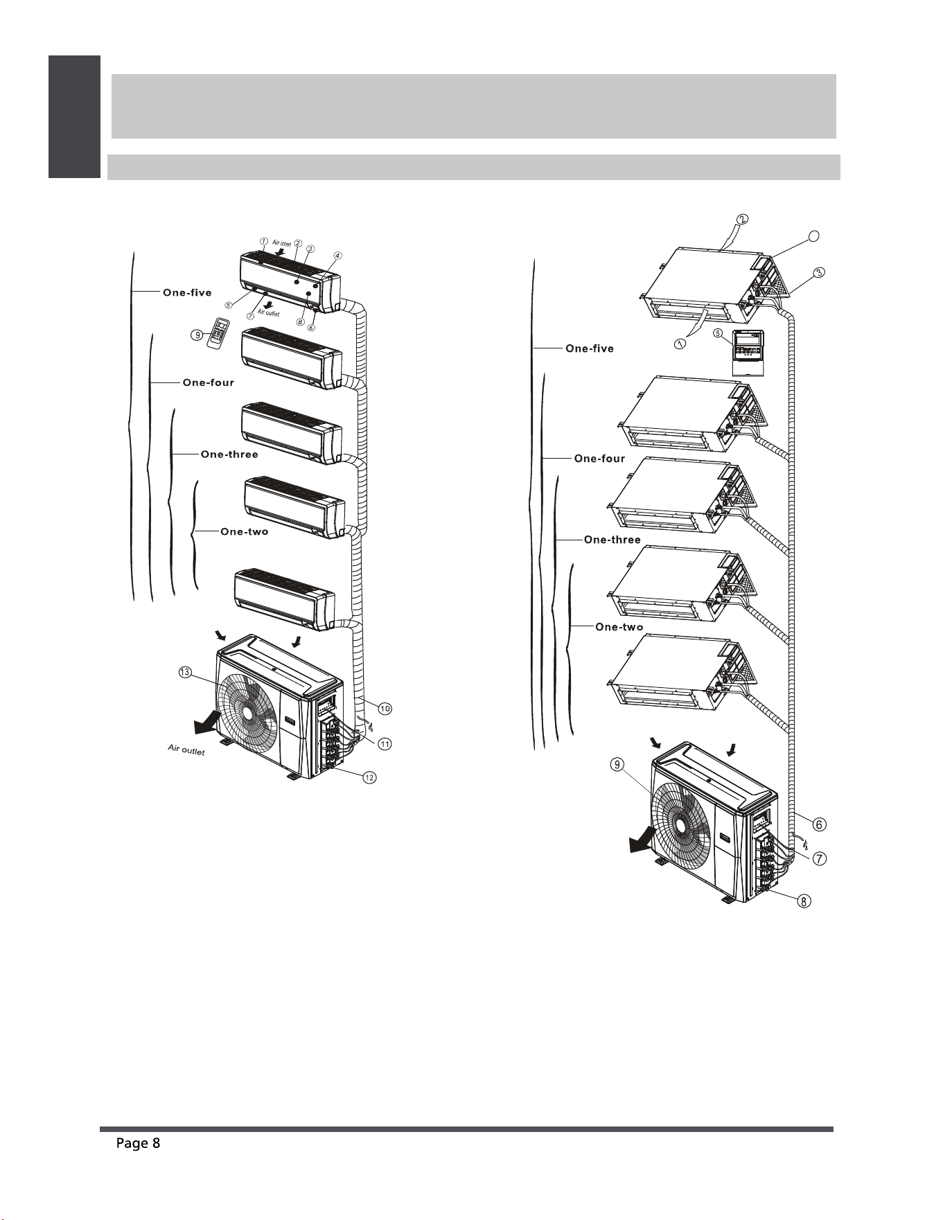
Unit Parts
Wall-mounted type Duct / Ceiling type
Indoor unit
1. Panel frame
2. Rear air intake grille
3. Front panel
4. Air purifying lter & Air lter(behind)
5. Horizontal louver
6. LCD display window
7. Vertical louver
8. Manual control button(behind)
9. Remote controller holder
Outdoor unit
10. Drain hose, refrigerant connecting pipe
11. Connective cable
12. Stop valve
13. Fan hood
Indoor unit
1. Air outlet
2. Air inlet
3. Air lter
4. Electric control cabinet
5. Wire controller
Outdoor unit
6. Drain hose, refrigerant connecting pipe
7. Connective cable
8. Stop valve
9. Fan hood
(A) (B)
e f
4
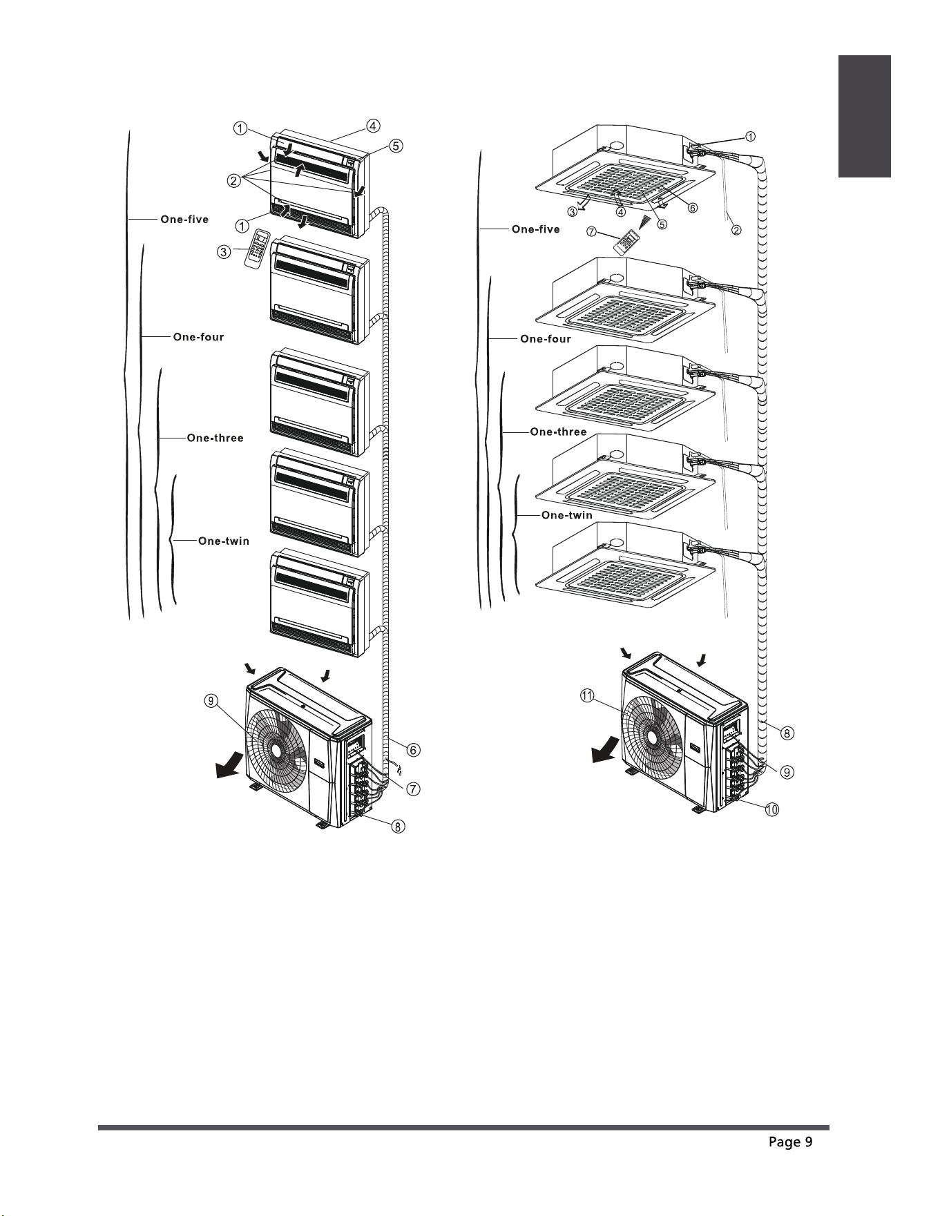
Unit Parts
And Major
Functions
e f
Floor and standing type(console) Compact four-way cassette type
Indoor unit
1. Air ow louver (at air outlet)
2. Air inlet (containing air lter)
3. Remote controller
4. Installation part
5. Display panel
Outdoor unit
6. Drain hose, refrigerant connecting pipe
7. Connective cable
8. Stop valve
9. Fan hood
Indoor unit
1. Drain pump(drain water from indoor unit)
2. Drain hose
3. Air outlet
4. Air inlet
5. Air-in grill
6. Display panel
7. Remote controller
Outdoor unit
8. refrigerant connecting pipe
9. Connective cable
10. Stop valve
11. Fan hood
(C) (D)
Unit Parts
And Major
Functions
e f
Operating Conditions
NOTE: For multi-split type air conditioners, one outdoor unit can be matched to dierent types of
indoor units. All of the pictures in this manual are for demonstration purposes only. Your air
conditioner may be slightly dierent, if similar in shape. The following pages introduce several kinds
of indoor units that can be matched with the outdoor units.
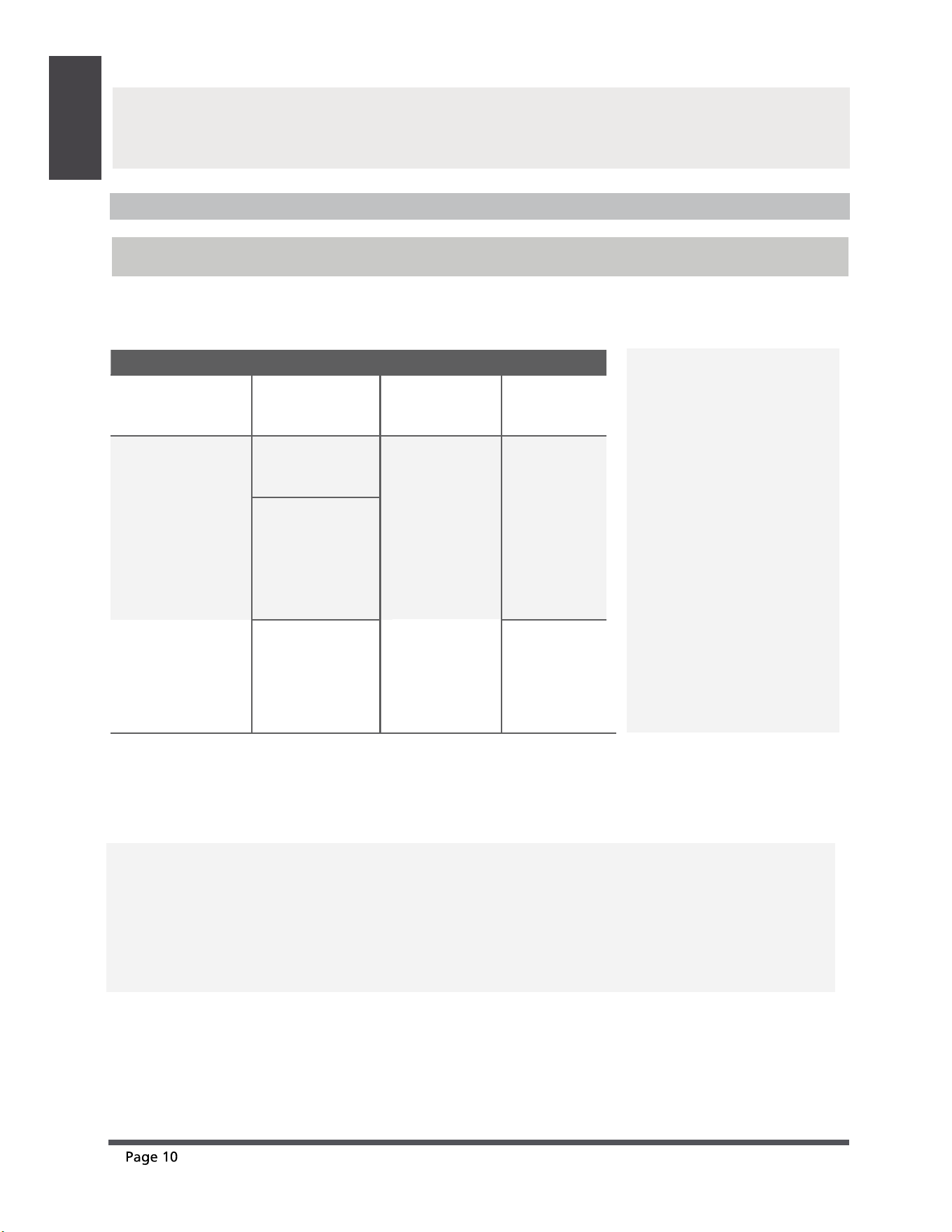
Operating temperature
When your air conditioner is used outside of the following temperature ranges, certain safety
protection features may activate and cause the unit to disable.
COOL mode HEAT mode DRY mode
Room Temperature
17°C - 32°C
(62°F - 90°F)
0°C - 30°C
(32°F - 86°F)
10°C - 32°C
(50°F - 90°F)
Outdoor
Temperature
0°C - 50°C
(32°F - 122°F)
-15°C - 24°C
(5°F - 75°F)
0°C - 50°C
(32°F - 122°F)
0°C - 52°C
(32°F - 126°F)
(For special
tropical models)
0°C - 52°C
(32°F - 126°F)
(For special
tropical models)
-15°C - 50°C
(5°F - 122°F)
(For models with
low temp. cooling
systems.)
FOR OUTDOOR UNITS
WITH AUXILIARY
ELECTRIC HEATER
When outside
temperature is below 0°C
(32°F ), we strongly
recommend keeping the
unit plugged in at all
time to ensure smooth
ongoing performance.
To further optimize the performance of your unit, do the following:
• Keep doors and windows closed.
• Limit energy usage by using TIMER ON and TIMER OFF functions.
• Do not block air inlets or outlets.
• Regularly inspect and clean air lters.
NOTE: Room relative humidity less than 80%. If the air conditioner operates in excess of this
gure, the surface of the air conditioner may attract condensation. Please sets the vertical air
ow louver to its maximum angle (vertically to the oor), and set HIGH fan mode.

e f
Unit Parts
And Major
Functions
Features
Protection of the air conditioner
Compressor protection
• The compressor cannot restart for 3 minutes
after it stops.
Anti-cold air (Cooling and heating models
only)
• The unit is designed not to blow cold air on
HEAT mode, when the indoor heat exchanger
is in one of the following three situations and
the set temperature has not been reached.
A) When heating has just started.
B) During defrosting.
C) Low temperature heating.
• The indoor or outdoor fan stop running when
defrosting (Cooling and heating models only).
Defrosting (Cooling and heating models only)
• Frost may be generated on the outdoor unit
during a heat cycle when outdoor temperature
is low and humidity is high resulting in lower
heating eciency in the air conditioner.
• Under these conditions, the air conditioner will
stop heating operations and start defrosting
automatically.
• The time to defrost may vary from 4 to 10
minutes, depending the outdoor temperature
and the amount of frost buildup on the
outdoor unit.
Auto-Restart (some models)
In case of power failure, the system will
immediately stop. When power returns, the
Operation light on the indoor unit will flash. To
restart the unit, press the ON/OFF button on the
remote control. If the system has an auto restart
function, the unit will restart using the same
settings.
White mist emerging from the indoor unit
• A white mist may be generated due to a large
temperature dierence between air inlet and
air outlet on COOL mode in places with high
relative humidity.
• A white mist may be generated due to moisture
created in the defrosting process when the air
conditioner restarts in HEAT mode operation
after defrosting.
Noise coming from the air conditioner
• You may hear a low hissing sound when the
compressor is running or has just stopped
running. This sound is the sound of the
refrigerant owing or coming to a stop.
• You may also hear a low "squeaking" sound
when the compressor is running or has just
stopped running. This is caused by tempera
heat expansion and cold contraction of the
plastic parts in the unit when the temperature
is changing.
• A noise may be heard due to the louver
restoring itself to its original position when
power is rst turned on.
Dust blowing out from the indoor unit.
This is happens when the air conditioner has not
been used for a long time or during its rst use.
Smell emitting from the indoor unit.
This is caused by the indoor unit giving o smells
permeated from building materials, furniture,or
smoke.
Unit Parts
And Major
Functions
e f
The air conditioner turns to FAN ONLY
mode from COOL or HEAT (for cooling
and heating models only) mode.
When the indoor temperature reaches the set
temperature setting, the compressor will stop
automatically, and the air conditioner turns to
FAN only mode. The compressor will start again
when the indoor temperature rises on COOL
mode or falls on HEAT mode to the set point.
Droplets of water may form on the surface of
the indoor unit when cooling occurs in relatively
high humidity (dened as higher than 80%).
Adjust the horizontal louver to the maximum air
outlet position and select HIGH fan speed.
Heating mode (For cooling and heating
models only)
The air conditioner draws in heat from the
outdoor unit and releases it via the indoor unit
during heating. When the outdoor temperature
falls, heat drawn in by the air conditioner
decreases accordingly. At the same time, heat
loading of the air conditioner increases due to
larger dierence between indoor and outdoor
temperature. If a comfortable temperature
cannot be achieved with the air conditioner
alone, it is recommended that you use a
supplementary heating device.
Lightning or a car wireless telephone operating
nearby may cause the unit to malfunction.
Disconnect the unit from its power source and
then re-connect the unit with the power source
again. Push the ON/OFF button on the remote
controller to restart operations.
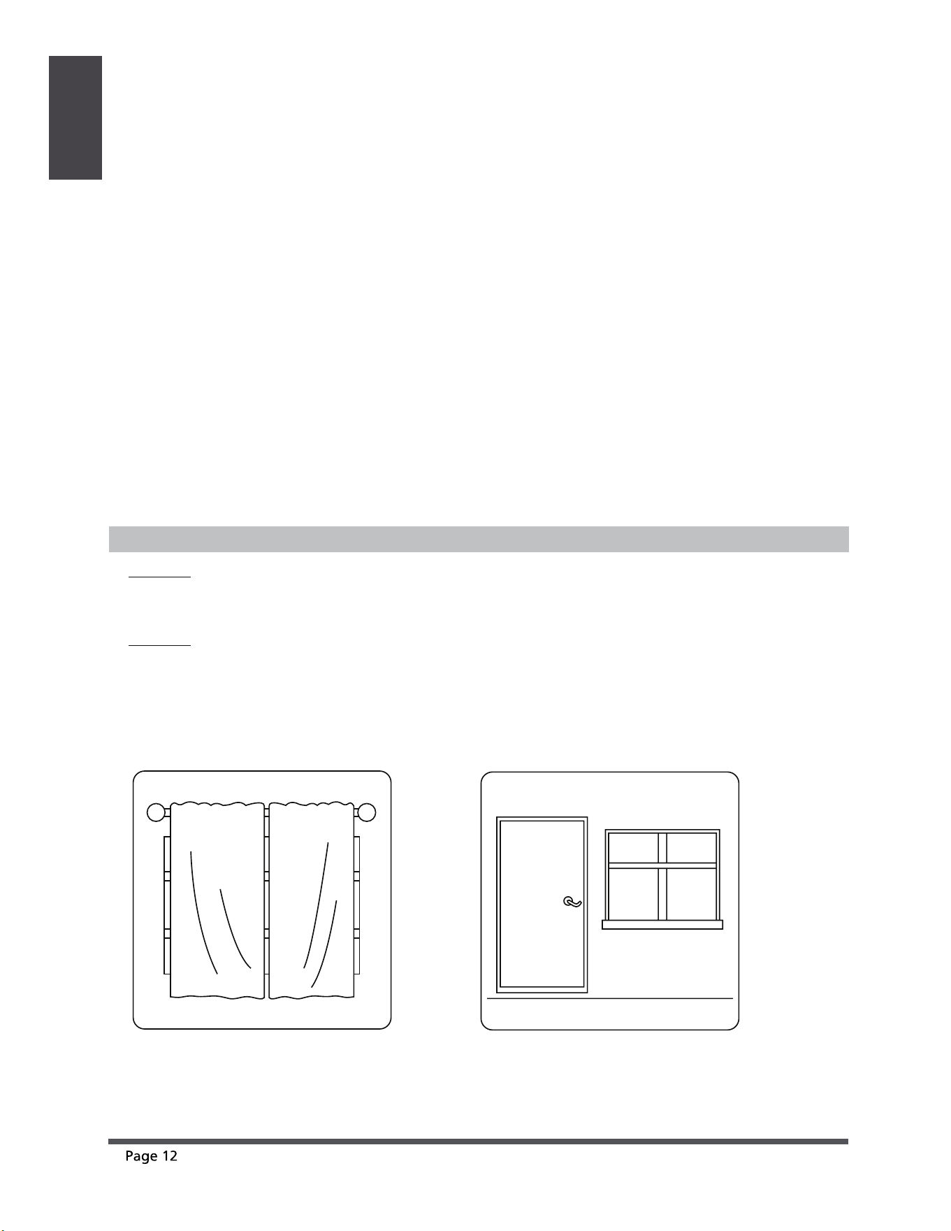
Energy Saving Tips
• DO NOT
set the unit to excessive temperature levels.
• While cooling, close the curtains to avoid direct sunlight.
• Doors and windows should be kept closed to keep cool or warm air in the room.
•
DO NOT
place objects near the air inlet and outlet of the unit. This will reduce the efficiency of the unit.
• Set a timer and use the built-in SLEEP/ECONOMY mode if applicable.
• If you don’t plan to use the unit for a long time, remove the batteries from the remote control.
• Clean the air filter every two weeks. A dirty filter can reduce cooling or heating efficiency.
• Adjust louvers properly and avoid direct airflow.
Closing curtains during heating also
helps keep the heat in
Doors and windows should be
kept closed
e f
Troubleshooting
Problem Possible Causes
Unit does not
turn on when
pressing ON/
OFF button
The unit has a 3-minute protection feature that prevents the unit from
overloading. The unit cannot be restarted within three minutes of being
turned o.
Cooling and Heating Models: If the Operation light and PRE-DEF (Pre-heating/
Defrost) indicators are lit up, the outdoor temperature is too cold and the unit’s
anti-cold wind is activated in order to defrost the unit.
In Cooling-only Models: If the “Fan Only” indicator is lit up, the outdoor
temperature is too cold and the unit’s anti-freeze protection is activated in
order to defrost the unit.
The unit changes
from COOL mode
to FAN mode
The unit changes its setting to prevent frost from forming on the unit. Once
the temperature increases, the unit will start operating again.
The set temperature has been reached, at which point the unit turns o the
compressor. The unit will resume operating when the temperature fluctuates
again.
The indoor unit
emits white mist
In humid regions, a large temperature dierence between the room’s air and
the conditioned air can cause white mist.
Both the indoor
and outdoor units
emit white mist
When the unit restarts in HEAT mode after defrosting, white mist may be
emitted due to moisture generated from the defrosting process.
Troubleshooting
Common Issues
The following problems are not a malfunction and in most situations will not require repairs.
SAFETY PRECAUTIONS
If any of the following conditions occurs, turn o your unit immediately!
• The power cord is damaged or abnormally warm
• You smell a burning odor
• The unit emits loud or abnormal sounds
• A power fuse blows or the circuit breaker frequently trips
• Water or other objects fall into or out of the unit
DO NOT ATTEMPT TO FIX THESE YOURSELF! CONTACT AN AUTHORIZED
SERVICE PROVIDER IMMEDIATELY!
Troubleshooting
Problem Possible Causes
Dust is emitted from
either the indoor or
outdoor unit
The unit may accumulate dust during extended periods of non-use, which
will be emitted when the unit is turned on. This can be mitigated by covering
the unit during long periods of inactivity.
The unit emits a
bad odor
The unit may absorb odors from the environment (such as furniture, cooking,
cigarettes, etc.) which will be emitted during operations.
The unit’s filters have become moldy and should be cleaned.
The fan of the
outdoor unit
does not operate
During operation, the fan speed is controlled to optimize product operation.
e f
The indoor unit
makes noises
A squeaking sound is heard when the system is OFF or in COOL mode. The
noise is also heard when the drain pump (optional) is in operation.
A squeaking sound may occur after running the unit in HEAT mode due to
expansion and contraction of the unit’s plastic parts.
Both the indoor
unit and outdoor
unit make noises
A low hissing sound may occur during operation. This is normal and is caused
by refrigerant gas flowing through both the indoor and outdoor units.
A low hissing sound may be heard when the system starts, has just stopped
running or is defrosting. This noise is normal and is caused by the refrigerant
gas stopping or changing direction.
The outdoor unit
makes noises
The unit will make dierent sounds based on its current operating mode.
e f
Troubleshooting
Troubleshooting Tips
When troubles occur, please check the following points before contacting a repair company.
Problem Possible Causes Solution
The unit
is not
working
Power failure Wait for the power to be restored
The power switch is o Turn on the power
The fuse is burned out Replace the fuse
Remote control batteries are dead Replace the remote control batteries
The unit’s 3-minute protection has
been activated
Wait three minutes after restarting the unit
Poor cooling
performance
Temperature setting may be higher
than the ambient room temperature
Lower the temperature setting
The heat exchanger on the indoor
or outdoor unit is dirty
Clean the aected heat exchanger
The air filter is dirty
Remove the filter and clean it according
to instructions
The air inlet or outlet of either unit
is blocked
Turn the unit o, remove the obstruction
and turn it back on
Doors and windows are open
Make sure that all doors and windows are
closed while operating the unit
Excessive heat is generated by
sunlight
Close windows and curtains during
periods of high heat or bright sunshine
Low refrigerant due to leak or
long-term use
Check for leaks, re-seal if necessary and
top o refrigerant
The unit
starts and
stops
frequently
There’s too much or too little
refrigerant in the system
Check for leaks and recharge the system
with refrigerant
There is air, incompressible gas or
foreign material in the refrigeration
system.
Evacuate and recharge the system with
refrigerant
System circuit is blocked
Determine which circuit is blocked and replace
the malfunctioning piece of equipment
The compressor is broken Replace the compressor
The voltage is too high or too low Install a manostat to regulate the voltage
Poor heating
performance
The outdoor temperature is lower
than 7°C (44.5°F)
Check for leaks and recharge the system
with refrigerant
Cold air is entering through doors
and windows
Make sure that all doors and windows are
closed during use
Low refrigerant due to leak or
long-term use
Check for leaks, re-seal if necessary and
top o refrigerant
ef
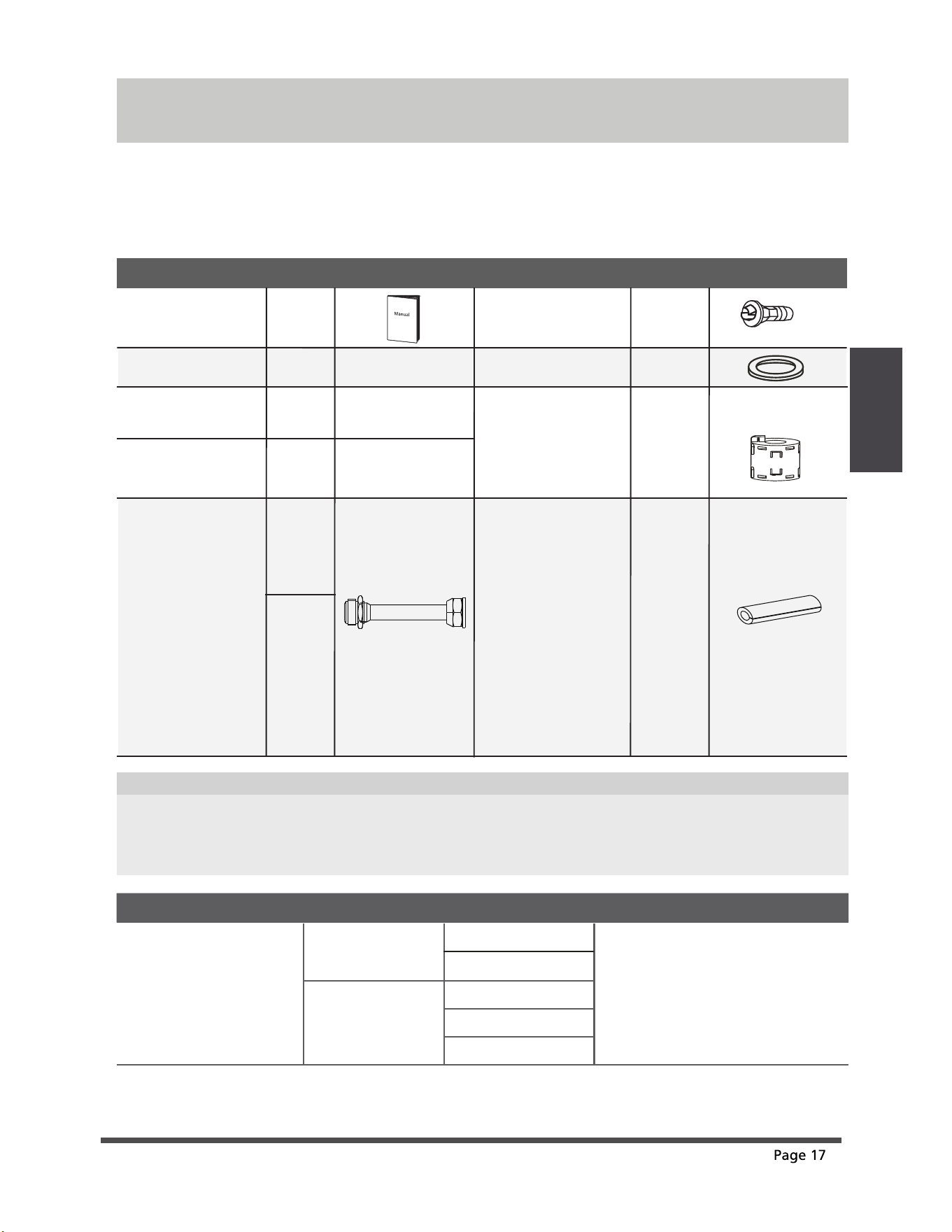
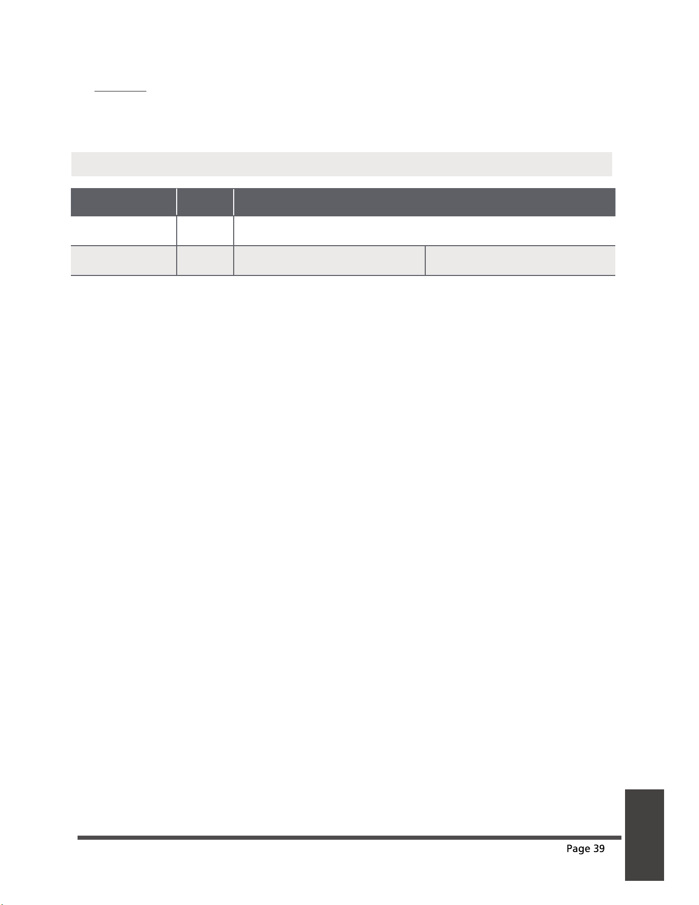
Accessories
Manual
Name
Shape Quantity(PC)
Parts you must purc hase
separately. Consult the dealer
about the proper pipe size of
the unit you purchased.
Connecting pipe
assembly
Liquid side
Gas side
6.35(1/4 in)
9.52(3/8in)
9.52(3/8in)
12.7(1/2in)
16(5/8in)
2~4
1
Name of Acce ssories
Q‘ty(pc)
Shape
1
1
Name of Acce ssories
Q‘ty(pc)
Shape
Installation plate
(some models)
Plastic expansion
sheath (some models)
Drain joint
(some models)
Seal ring
(some models)
Magnetic ring (Hitch
it on the connective
cable between indoor
unit and outdoor unit
after installation.)
(some models)
Accessories
Optional accessories
There are two types of remote controls: wired and wireless.
Select a remote controller based on customer preferences and requirements and install in an
appropriate place.
Refer to catalogues and technical literature for guidance on selecting a suitable remote controller.
•
The air conditioning system comes with the following accessories. Use all of the installation parts and
accessories to install the air conditioner. Improper installation may result in water leakage, electrical
shock and re, or cause the equipment to fail. The items are not included with the air conditioner must
be purchased separately.
Varies
by model
Self-Tapping Screw A
(some models)
5-8
Optional
part
(one piece/
one indoor
unit)
Optional
part
(1-5 pieces
for outdoor
unit,
depending
on models)
Transfer connector
(packed with the
indoor or outdoor
unit, depending on
models)
NOTE: Pipe size may
differ from appliance
to appliance. To meet
different pipe size
requirements,
sometimes the pipe
connections need a
transfer connector
installed on the
outdoor unit .
1
Cord protection rubber
ring(If the cord clamp
cannot fasten on a
small cord, use the
cord protection rubber
ring [supplied with
accessories] to wrap
around the cord. Then
fix it in place with the
cord clamp.)
(some models)
5-8
(depending
on models)
(depending
on models)
ef
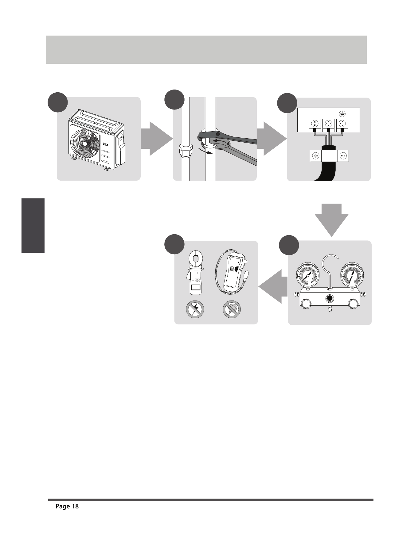
Installation Summary
INSTALLATION ORDER
LN
1
2
3
MC MC
4
5
Install the outdoor unit
Evacuate the refrigeration
system
Connect the wires
Connect the refrigerant pipes
Perform a test run
Installation
Summary
(L1) (L2)
ef
Outdoor Unit
Installation
Diagram
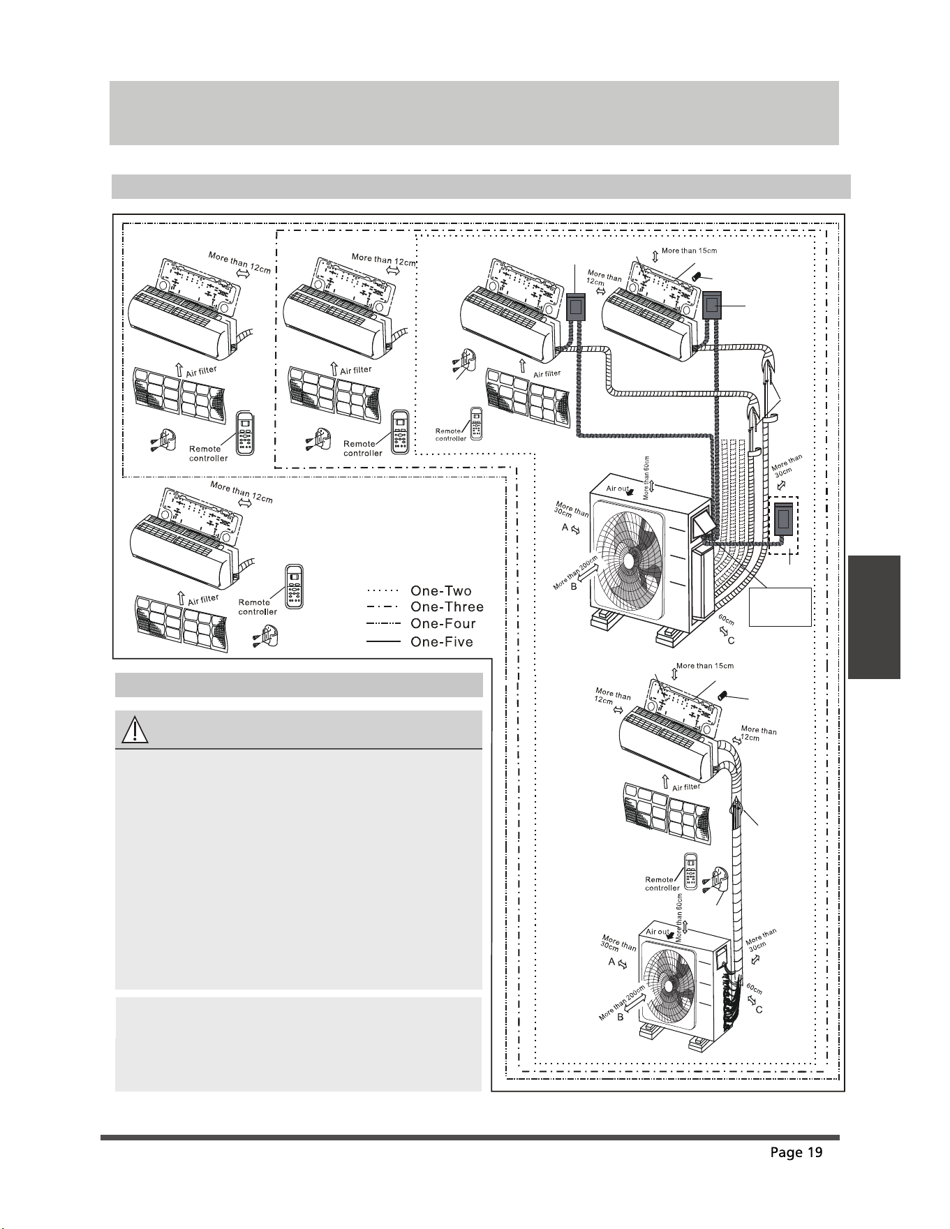
Installation Diagram
Installation Diagram
Installation
plate
Mounting screw
ST3.9
h25-C-H
Refrigerant
pipe
Remote
controller
holder
Clip anchor
(2)
•
This illustration is for demonstration
purposes only.
The actual shape of your air condtioner may
be slightly dierent.
Copper lines must be independently insulated.
•
•
CAUTION
•
To prevent wall damage, use a stud nder to
locate studs.
A minimum pipe run of 3 metres is required
to minimise vibration & excessive noise.
Two of the A, B, and C air circulation pathways
must be free from obstructions at all times.
•
•
NOTE: The installation must be performed in
accordance with the requirement of local and
national standards. The installation may be
slightly dierent in dierent areas.
Safety Precautions
1
2
3
5
4
1
Installation plate
Mounting screw
ST3.9
h25-C-H
Clip anchor
(1)
Remote
controller
holder
5 4 3
2
The maximum
amount of the
connection cables is 5.
This section is for
reference only.
Air-break Switch
Drainage
Pipe
Air-break
Switch
Outdoor Unit
Power Cable
More than
More than
Specifications
ef
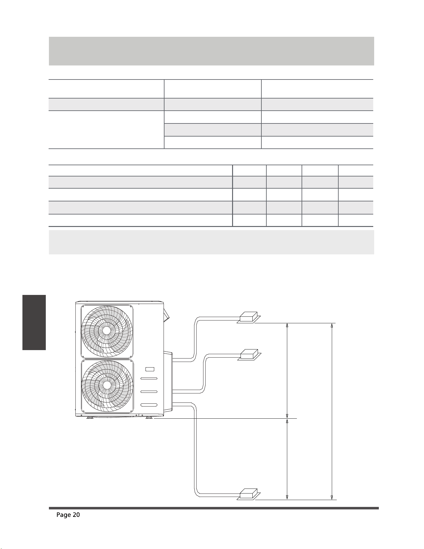
Specifications
Number of units that can be used
together
Connected units
1-5 units
Compressor stop/start frequency Stop time 3 min or more
voltage uctuation within ±10% of rated voltage
Power source voltage
voltage drop during start within ±15% of rated voltage
interval unbalance within ±3% of rated voltage
Unit: m/ft.
10m(32.8ft)
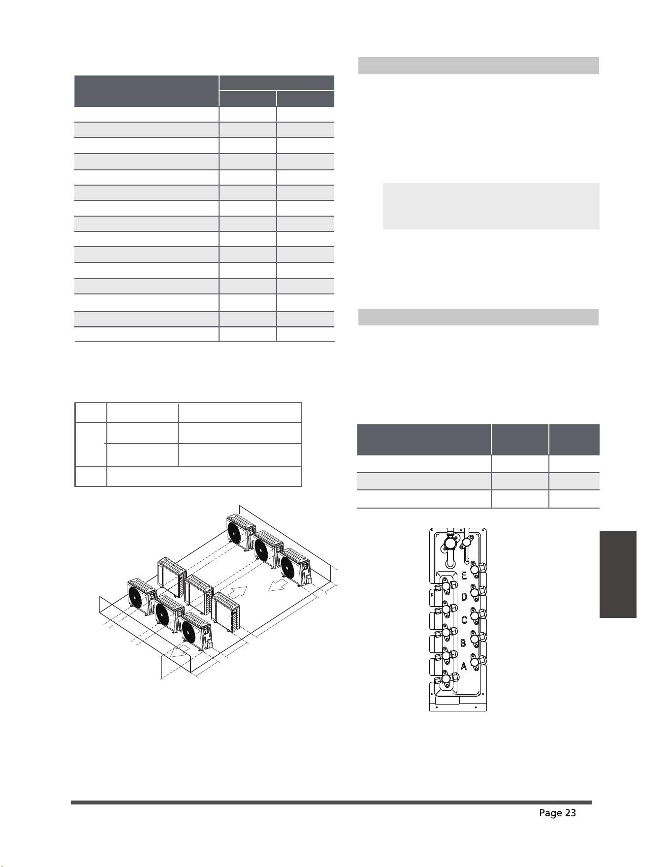
When installing multiple indoor units with a single outdoor unit, ensure that the length of the
refrigerant pipe and the drop height between the indoor and outdoor units meet the requirements
illustrated in the following diagram:
Indoor unit
Indoor unit
Indoor unit
Outdoor unit
15m(49ft)
15m(49ft)
Max.Height dierence
1 drive 2 1 drive 3
Max. length for all rooms 40/131 60/197
Max. length for one indoor unit 25/82 30/98
Max. height dierent between indoor and outdoor unit
15/49 15/49
Max. height dierent between indoor units 10/33 10/33
1 drive 4 1 drive 5
80/262 80/262
35/115 35/115
15/49 15/49
10/33 10/33
NOTE: For the units adopt quick connectors, no more than two pipes can be connected, and the Max.
length for each pipe is 7.5 meters.
Outdoor Unit
Installation
ef
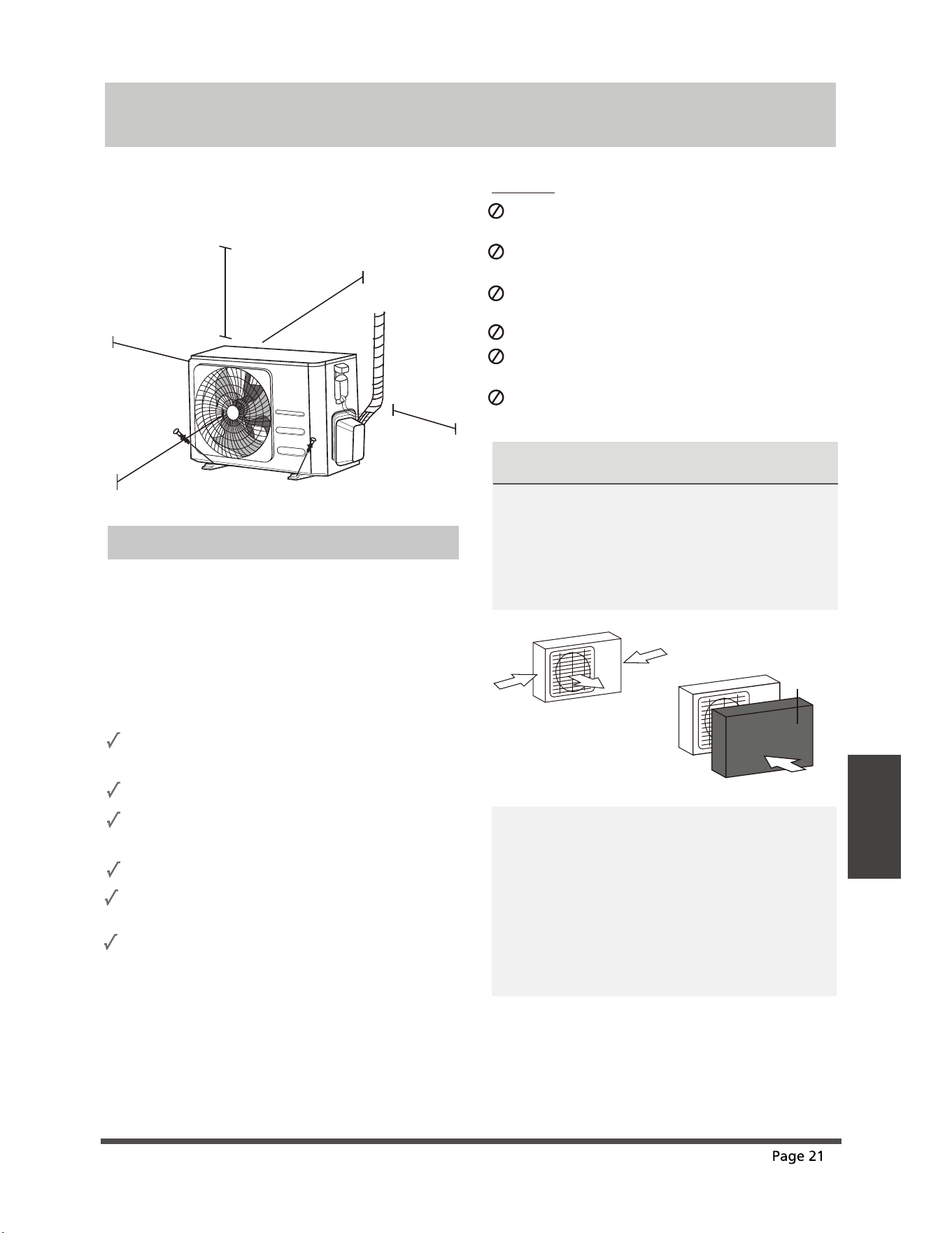
Outdoor Unit Installation
evoba )ni42( mc06
60cm (24in)
on righ
t
30cm (12in)
on left
200cm (79in)
in fron
t
30cm (12in)
from back wall
Installation Instructions – Outdoor unit
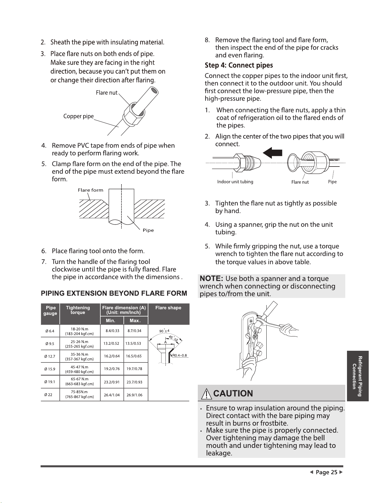
Step 1: Select installation location
Before installing the outdoor unit, you must
choose an appropriate location. The following are
standards that will help you choose an appropriate
location for the unit.
Proper installation locations meet the
following standards:
Meets all spatial requirements shown in
Installation Space Requirements above.
Good air circulation and ventilation
Firm and solid—the location can support the
unit and will not vibrate
Noise from the unit will not disturb others
Install the unit by following local codes and
regulations , there may be dier slightly
between dierent regions.
SPECIAL CONSIDERATIONS FOR EXTREME
WEATHER
If the unit is exposed to heavy wind:
Install unit so that air outlet fan is at a 90°
angle to the direction of the wind. If needed,
build a barrier in front of the unit to protect it
from extremely heavy winds.
See Figures below.
Strong
wind
Strong wind
Strong wind
If the unit is frequently exposed to heavy
rain or snow:
Build a shelter above the unit to protect
it from the rain or snow. Be careful not to
obstruct air flow around the unit.
If the unit is frequently exposed to salty air
(seaside):
Use outdoor unit that is specially designed to
resist corrosion.
Wind Baffle
Protected from prolonged periods of direct
sunlight or rain
DO NOT
install unit in the following locations:
Near an obstacle that will block air inlets
and outlets
Near a public street, crowded areas, or
where noise from the unit will disturb others
Near animals or plants that will be harmed
by hot air discharge
Near any source of combustible gas
In a location that is exposed to large
amounts of dust
In a location exposed to a excessive amounts
of salty air
Where snowfall is anticipated, take
appropriate measures to prevent ice
buildup and coil damage.
Outdoor Unit
Installation
ef
IN COLD CLIMATES
In cold climates, make sure that the drain hose
is as vertical as possible to ensure swift water
drainage. If water drains too slowly, it can
freeze in the hose and ood the unit.
The outdoor unit can be anchored to the
ground or to a wall-mounted bracket with
bolt(M10). Prepare the installation base of the
unit according to the dimensions below.
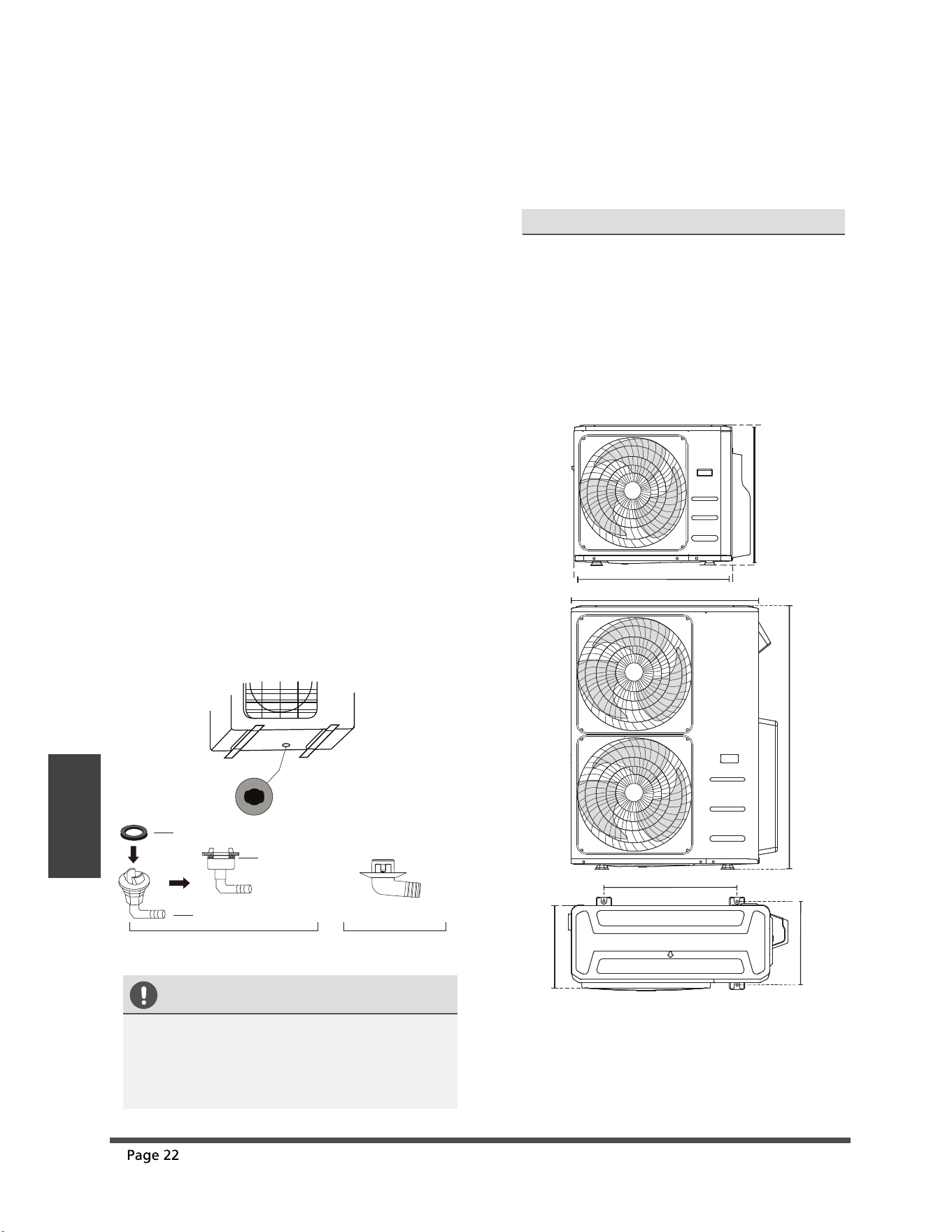
Step 3: Anchor outdoor unit
UNIT MOUNTING DIMENSIONS
The following is a list of dierent outdoor
unit sizes and the distance between their
mounting feet. Prepare the installation base
of the unit according to the dimensions
below.
Split Type Outdoor Unit
A
B
D
W
H
W
H
Outdoor Unit Types and Specifications
Step 2: Install drain joint
(Heat pump unit only)
Before bolting the outdoor unit in place, you must
install the drain joint at the bottom of the unit.
Note that there are two dierent types of drain
joints depending on the type of outdoor unit.
If the drain joint comes with a rubber seal
(see Fig. A ), do the following:
1. Fit the rubber seal on the end of the drain joint
that will connect to the outdoor unit.
2. Insert the drain joint into the hole in the base
pan of the unit.
3. Rotate the drain joint 90° until it clicks in place
facing the front of the unit.
4. Connect a drain hose extension (not included)
to the drain joint to redirect water from the
unit during heating mode.
If the drain joint doesn’t come with a rubber
seal (see Fig. B ), do the following:
1. Insert the drain joint into the hole in the base
pan of the unit. The drain joint will click in
place.
2. Connect a drain hose extension (not included)
to the drain joint to redirect water from the
unit during heating mode.
Seal
Drain joint
(A) (B)
Base pan hole of
outdoor unit
Seal
Outdoor Unit
Installation
ef
When Select a 24K Indoor Unit
The 24K indoor unit can only be connected with
an A system. If there are two 24K indoor units,
they can be connected with A and B systems.
Connective pipe size of an A and B system
(unit: inch)
Indoor Unit capacity
(Btu/h)
Liquid Gas
7K/9K/12K 1/4 3/8
12K/18K 1/4 1/2
24K 3/8 5/8
Notes On Drilling Hole In Wall
You must drill a hole in the wall for the
refrigerant piping, and the signal cable that will
connect the indoor and outdoor units.
1.
Determine the location of the wall hole
based on the location of the outdoor unit.
2.
Using a 65-mm (2.5”) core drill, drill a hole
in the wall.
NOTE: When drilling the wall hole, make
sure to avoid wires, plumbing, and other
sensitive components.
3.
Place the protective wall cu in the hole.
This protects the edges of the hole and
helps seal it when you nish the
installation process.
(unit: mm/inch)
Outdoor Unit Dimensions
W x H x D
Mounting Dimensions
Distance A Distance B
760x590x285 (29.9x23.2x11.2) 530 (20.85) 290 (11.4)
810x558x310 (31.9x22x12.2) 549 (21.6) 325 (12.8)
845x700x320 (33.27x27.5x12.6) 560 (22) 335 (13.2)
900x860x315 (35.4x33.85x12.4) 590 (23.2) 333 (13.1)
945x810x395 (37.2x31.9x15.55) 640 (25.2) 405 (15.95)
990x965x345 (38.98x38x13.58) 624 (24.58) 366 (14.4)
946x810x420 (37.2x31.9x16.53) 673 (26.5)
403 (15.87)
946x810x410 (37.2x31.9x16.14) 673 (26.5)
403 (15.87)
952x1333x410 (37.5x52.5x16.14) 634 (24.96)
404 (15.9)
952x1333x415 (37.5x52.5x16.14) 634 (24.96)
404 (15.9)
845x702x363 (33.27x27.6x14.3)
540 (21.26)
350 (13.8)
938x1369x392 (36.93x53.9x15.43) 634 (24.96) 404 (15.9)
900x1170x350 (35.4x46x13.8) 590 (23.2) 378 (14.88)
800x554x333 (31.5x21.8x13.1) 514 (20.24) 340 (13.39)
Rows of series installation
L ≤ H
L ≤ 1/2H
LA
25 cm / 9.8” or more
1/2H < L ≤ H
30 cm / 11.8” or more
L > H
Can not be installed
The relations between H, A and L are
as follows.
L
H
300 cm / 118” or more
A
60 cm / 23.6”
or more
150 cm / 59”
or more
25 cm / 9.8”
or more
25 cm / 9.8”
or more
890x673x342 (35.0”x 26.5”x 13.5”)
663 (26.1”)
354 (13.9”)
ECR Model
MHMZ218DA
MHMZ327DA
MHMZ436DA
MHMZ548DA
2 x Φ6.35 (1/4)
3 x Φ6.35 (1/4)
4 x Φ6.35 (1/4)
5 x Φ6.35 (1/4)
2 x Φ9.52 (3/8)
3 x Φ9.52 (3/8)
3 x Φ9.52 (3/8) + 1 x Φ12.7 (1/2)
3 x Φ9.52 (3/8)+ 2 x Φ12.7 (1/2)
Liquid Side mm(in) Gas Side mm(in)
Wiring
ef
BEFORE PERFORMING ANY
ELECTRICAL WORK, READ
THESE REGULATIONS
1. All wiring must comply with local and national
electrical codes, regulations and must be
installed by a licensed electrician.
2. All electrical connections must be made
according to the Electrical Connection Diagram
located on the panels of the indoor and outdoor
units.
3. If there is a serious safety issue with the power
supply, stop work immediately. Explain your
reasoning to the client, and refuse to install the
unit until the safety issue is properly resolved.
4. Power voltage should be within 90-110% of
rated voltage. Insucient power supply can
cause malfunction, electrical shock, or re.
5. If connecting power to xed wiring, a
surgeprotector and main power switch should
be installed.
6. If connecting power to xed wiring, a switch
or circuit breaker that disconnects all poles and
has a contact separation of at least 1/8in (3mm)
must be incorporated in the xed wiring. The
qualied technician must use an approved
circuit breaker or switch.
13.
Make sure that you do not cross your
electrical wiring with your signal wiring.
This may cause distortion and
interference.
14.
The unit must be connected to the
main outlet. Normally, the power supply
must have a impedance of 32 ohms.
15.
No other equipment should be
connected to the same power circuit.
16.
Connect the outdoor wires before
connecting the indoor wires.
7. Only connect the unit to an individual branch
circuit outlet. Do not connect another
appliance to that outlet.
8. Make sure to properly ground the air conditioner.
9. Every wire must be rmly connected. Loose
wiring can cause the terminal to overheat,
resulting in product malfunction and possible re.
Do not let wires touch or rest against refrigerant
tubing, the compressor, or any moving parts
within the unit.
If the unit has an auxiliary electric heater, it must
be installed at least 1 meter (40in) away from
any combustible materials.
To avoid getting an electric shock, never touch
the electrical components soon after the power
supply has been turned o. After turning o
the power, always wait 10 minutes or more
before you touch the electrical components.
10.
11.
12.
WARNING
BEFORE PERFORMING ANY
ELECTRICAL OR WIRING WORK,
TURN OFF THE MAIN POWER TO
THE SYSTEM.
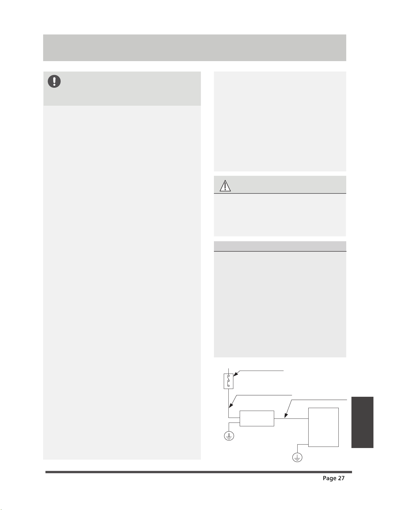
Wiring
NOTE ON AIR SWITCH
When the maximum current of the air
conditioner is more than 16A, an air
switch or leakage protection switch with
protective device shall be used
(purchased seperately) .
When the maximum current of the air
conditioner is less than 16A, the power
cord of air conditioner shall be
equipped with plug (purchased
seperately).
The North American market is wired
according to NEC and CEC requirements.
Indoor unit
Outdoor unit
Air switch
(purchased seperately)
(purchased seperately)
Outdoor unit power wires
Indoor & Outdoor
connective wires
(A)
ef
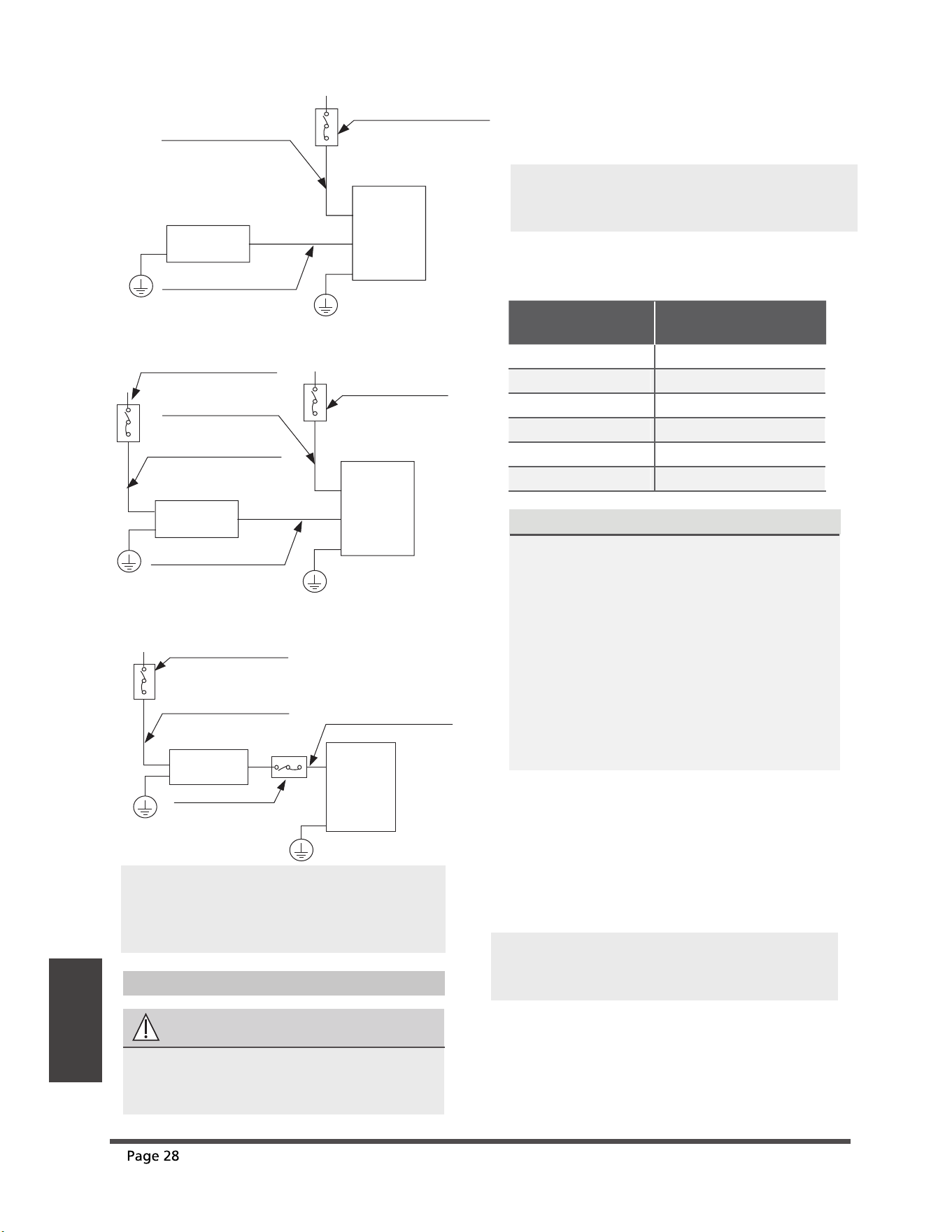
Wiring
Outdoor Unit Wiring
WARNING
Before performing any electrical or wiring
work, turn o the main power to the
system.
1. Prepare the cable for connection
a. You must rst choose the right cable
size. Be sure to use H07RN-F cables.
NOTE: The cographs are for explanation
purpose only. Your machine may be
slightly dierent. The actual shape shall
prevail.
Indoor unit
Outdoor unit
Air switch
(purchased seperately)
Air switch
(purchased seperately)
(purchased seperately)
Indoor unit power wires
Indoor & Outdoor
connective wires
Outdoor unit power wires
Indoor unit
Outdoor unit
Air switch
(purchased seperately)
(purchased seperately)
Indoor unit power wires
Indoor & Outdoor
connective wires
(B)
(C)
Indoor unit
Outdoor unit
Air switch
Air switch
(purchased seperately)
(Only for the North American)
(purchased seperately)
(purchased seperately)
Outdoor unit power wires
Indoor & Outdoor
connective wires
(D)
Minimum Cross-Sectional Area of
Power and Signal Cables (For reference)
Rated Current of
Appliance (A)
Nominal Cross-Sectional
Area (mm²)
> 3 and d 6
0.75
> 6 and d 10
1
> 10 and d 16
1.5
> 16 and d 25
2.5
> 25 and d 32
4
> 32 and d 40
6
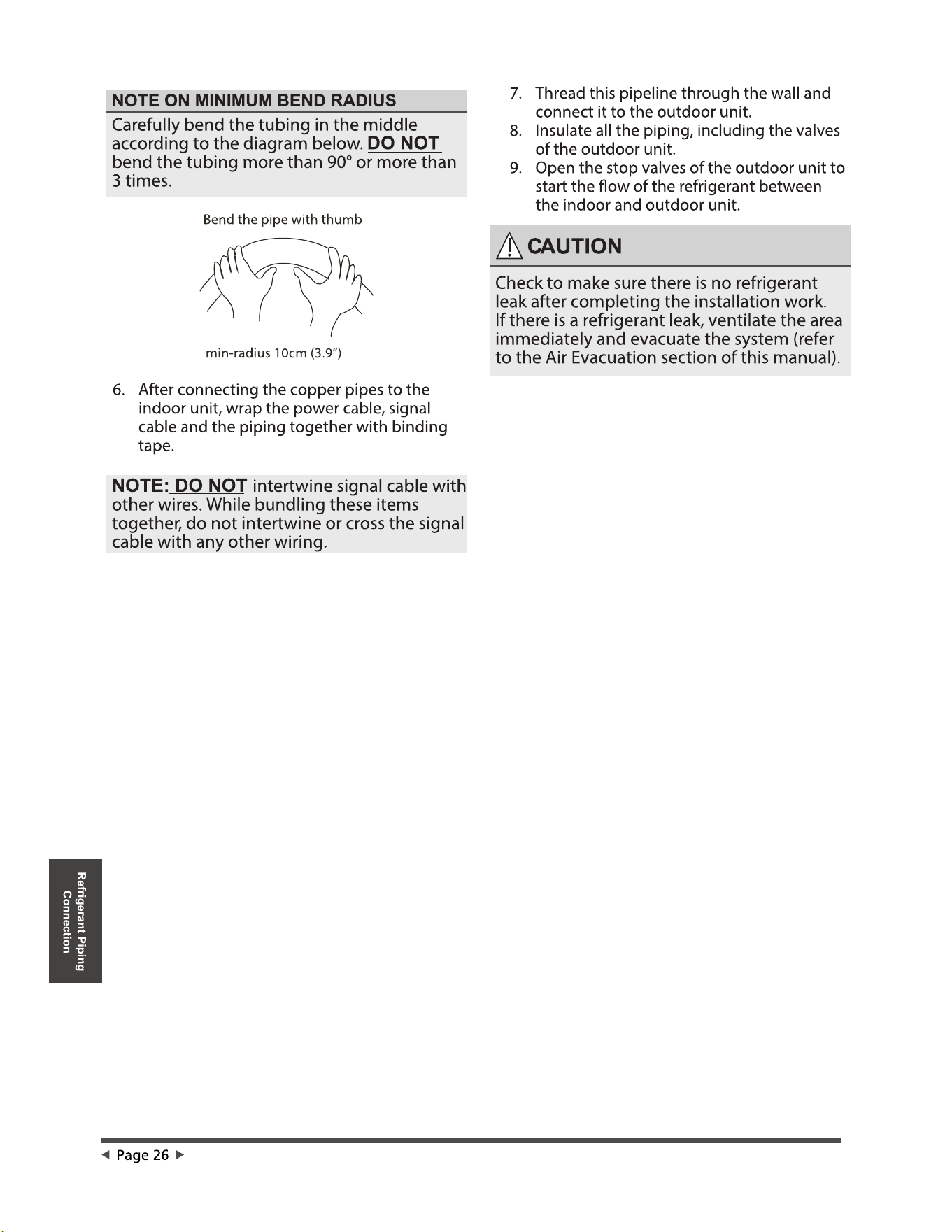
Using a wire crimper, crimp u-lugs on the
ends.
b. Using wire strippers, strip the rubber
jacketfrom both ends of the signal cable
to reveal approximately 15cm (5.9”) of
wire.
c.
Strip the insulation from the ends.
d.
NOTE: When connecting the wires, strictly
follow the wiring diagram found inside the
electrical box cover.
NOTE: In North America, choose the cable
type according to the local electrical codes
and regulations.
CHOOSE THE RIGHT CABLE SIZE
The size of the power supply cable, signal
cable, fuse, and switch needed is determined
by the maximum current of the unit. The
maximum current is indicated on the nameplate
located on the side panel of the unit. Refer to
this nameplate to choose the right cable, fuse,
or switch.
NOTE: In North America, please choose the
right cable size according to the Minimum
Circuit Ampacity indicated on the nameplate
of the unit.
ef
Wiring
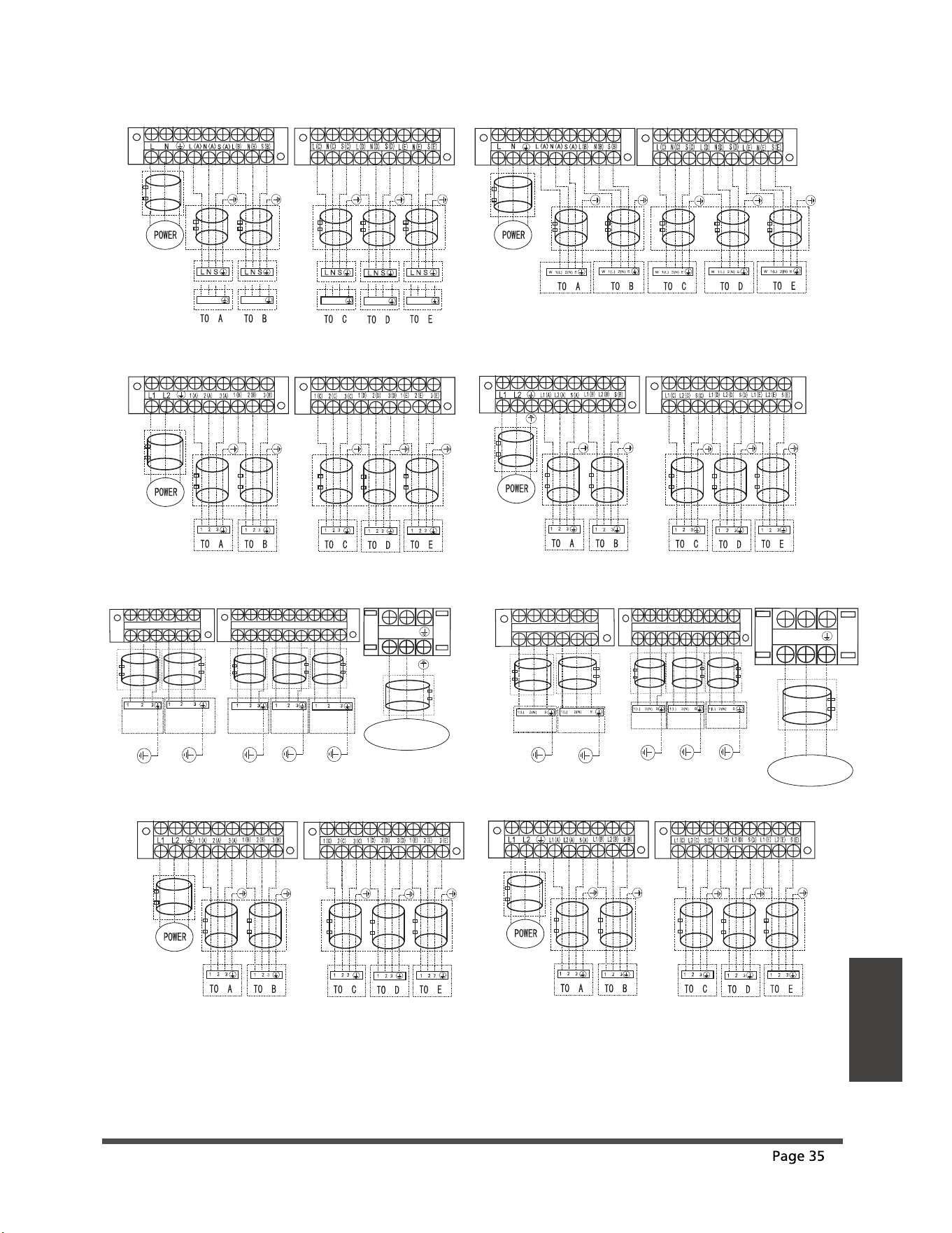
Wiring Figure
3. Connect the u-lugs to the terminals Match the wire colors/labels with the labels on
the terminal block, and rmly screw the u-lug of each wire to its corresponding terminal.
4. Clamp down the cable with designated cable clamp.
5. Insulate unused wires with electrical tape. Keep them away from any electrical or metal parts.
6. Reinstall the cover of the electric control box.
Harmonic declaration
"The equipment M4OB-36HFN8-Q complies with IEC 61000-3-12 provided that the shortcircuit power
Ssc is greater than or equal to 4787737.5 at the interface point between the user’s supply and the
public system. It is the responsibility of the installer or user of the equipment to ensure, by
consultation with the distribution network operator if necessary, that the equipment is con-nected
only to a supply with a short-circuit power Ssc greater than or equal to 4787737.5."
"The equipment M5OD-42HFN8-Q complies with IEC 61000-3-12 provided that the shortcircuit power
Ssc is greater than or equal to 3190042.5 at the interface point between the user’s supply and the
public system. It is the responsibility of the installer or user of the equipment to ensure, by
consultation with the distribution network operator if necessary, that the equipment is con-nected
only to a supply with a short-circuit power Ssc greater than or equal to 3190042.5."
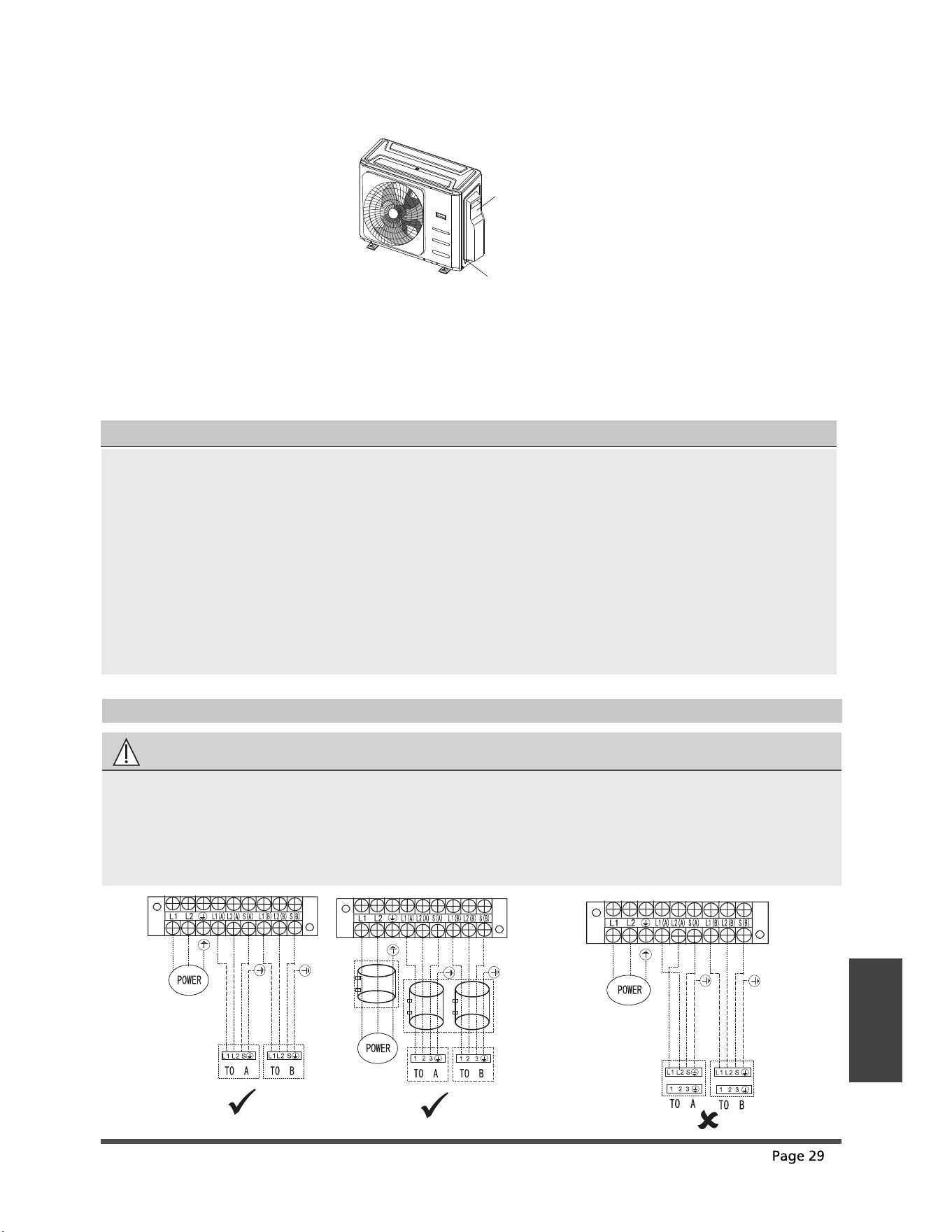
CAUTION
Connect the connective cables to the terminals, as identied, with their matching numbers
on the terminal block of the indoor and outdoor units. For example, Terminal L1(A) of the
outdoor unit must connect with terminal L1/1 on the indoor unit. The outdoor unit can
match dierent types of indoor unit, the numbers on the terminal block of the indoor unit
may be slightly dierent. Please pay special attention while connecting the wire.
OPTIONAL
2.
Cover
Screw
Remove the electric cover of the outdoor unit. If there is no cover on the outdoor unit, take
o the bolts from the maintenance board and remove the protection board.
or
or
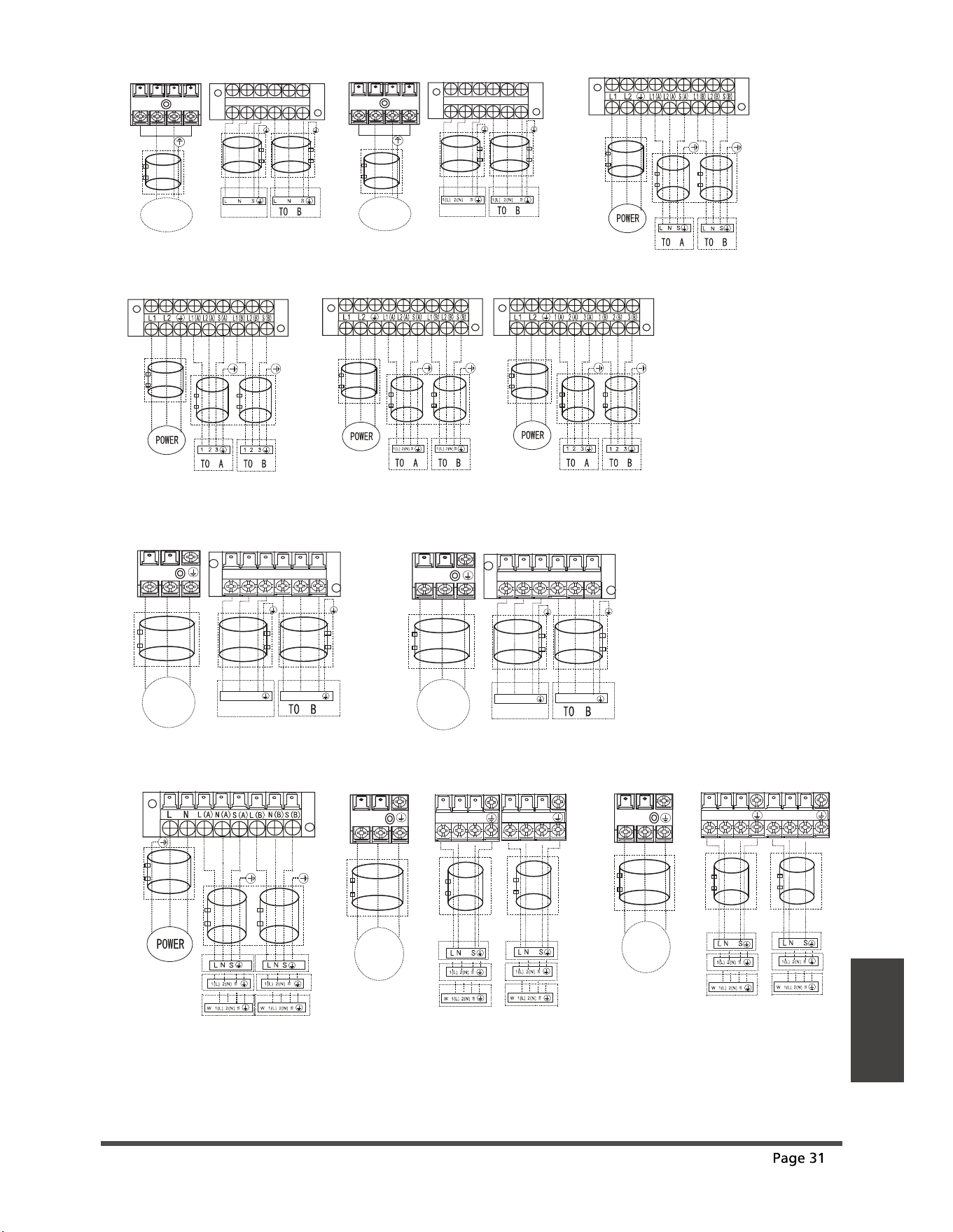
One-two models:
Model I
Model J
NOTE:Use the magnetic ring ( not supplied, optional part) to hitch the connective cable of
indoorand outdoor units after installation.One magnetic ring is used for one cable.
S(B)
N(A)
N(B)
L(B)
L
L(A)
N
S(A)
POWER
or
1(L) 2(N) 3(S)
1(L) 2(N) 3(S)
or
SUPPLY
TO B
TO A
S(2)
S(1)
POWER
6833/<
L(A)
S(A)
N(A)
L(B)
N(B)
S(B)
Y/G
:
/
1
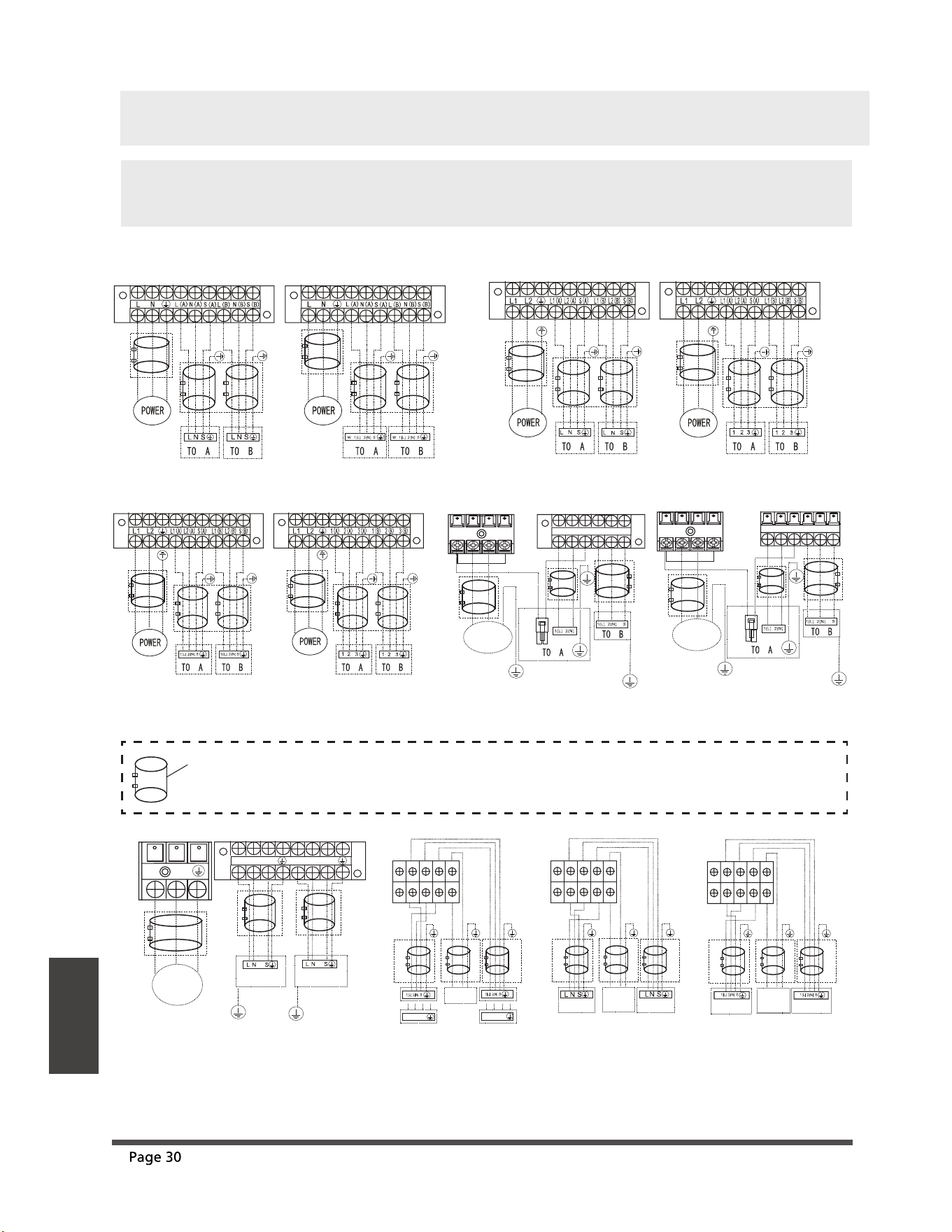
/
NOTE: Refer to the following gures if end-users wish to perform their own wiring.
Run the main power cord through the lower line-outlet of the cord clamp.
---- This symbol indicates eld wiring.
Y/G
72%
L(A)
N(A)
S(A)
L(B)
N(B)
S(B)
POWER
6833/<
N
L
Y/G
72$
S(B)
N(A)
N(B)
L(B)
L
L(A)
N
S(A)
POWER
SUPPLY
TO B
TO A
S(2)
S(1)
Model E Model F Model G
Model C Model D
OPTIONAL
OPTIONAL
OPTIONAL
OPTIONAL
OPTIONAL
POWER
6833/<
L(A)
S(A)
N(A)
L(B)
N(B)
S(B)
Y/G
:
/
1
/
Model H
OPTIONAL
OPTIONAL
OPTIONAL
Model L
OPTIONAL
OPTIONAL
OPTIONAL
OPTIONAL
OPTIONAL
OPTIONAL
OPTIONAL
OPTIONAL
OPTIONAL
OPTIONAL
OPTIONAL
OPTIONAL
OPTIONAL
OPTIONAL
OPTIONAL
OPTIONAL
OPTIONAL
OPTIONAL
OPTIONAL
W
W
Model K
S(B)
N(A)
N(B)
L(B)
L
L(A)
N
S(A)
POWER
SUPPL
Y
TO B
TO A
S(2)
S(1)
OPTIONAL
OPTIONAL
OPTIONAL
ef
Wiring
Model A Model B
OPTIONAL
OPTIONAL
OPTIONAL
OPTIONAL
OPTIONAL
OPTIONAL
NOTE: For quick-connector models, please refer to <<Owner’s Manual & Installation Manual >>
packed with the indoor unit.
Wiring
Model R
OPTIONAL
POWER
6833/<
L(A)
S(A)
N(A)
L(B)
N(B)
S(B)
:
/
1
/
OPTIONAL
OPTIONAL
OPTIONAL
1(A)
3(A)
2(A)
1(B)
2(B)
3(B)
Model U
Model V
Model W
Model S
OPTIONAL
OPTIONAL
POWER
6833/<
L(A)
S(A)
N(A)
L(B)
N(B)
S(B)
:
/
1
/
OPTIONAL
OPTIONAL
OPTIONAL
Model M Model N Model O
OPTIONAL
OPTIONAL
OPTIONAL
OPTIONAL
OPTIONAL
OPTIONAL
OPTIONAL
OPTIONAL
Model P Model Q
OPTIONAL
OPTIONAL
OPTIONAL
OPTIONAL
OPTIONAL
OPTIONAL
L(A) N(A) S(A)
L(B) N(B) S(B)
72$
72$
72$
OPTIONAL
OPTIONAL
L1 L2
OPTIONAL
POWER
SUPPLY
L N
L N
OPTIONAL
POWER
SUPPLY
Model T
L(A) N(A) S(A)
L(B) N(B) S(B)
OPTIONAL
OPTIONAL
OPTIONAL
POWER
SUPPLY
1 2 3 1 2 3
L1(A)
S(A)
L2(A)
L1(B)
L2(B)
S(B)
OPTIONAL
OPTIONAL
72$
L1 L2
OPTIONAL
POWER
SUPPLY
1 2 3 1 2 3
ef
or
or
To indoor
unit A
To indoor
unit B
or
or
To indoor
unit A
or
or
To indoor
unit B
or
or
To indoor
unit A
To indoor
unit B
or
or
Wiring
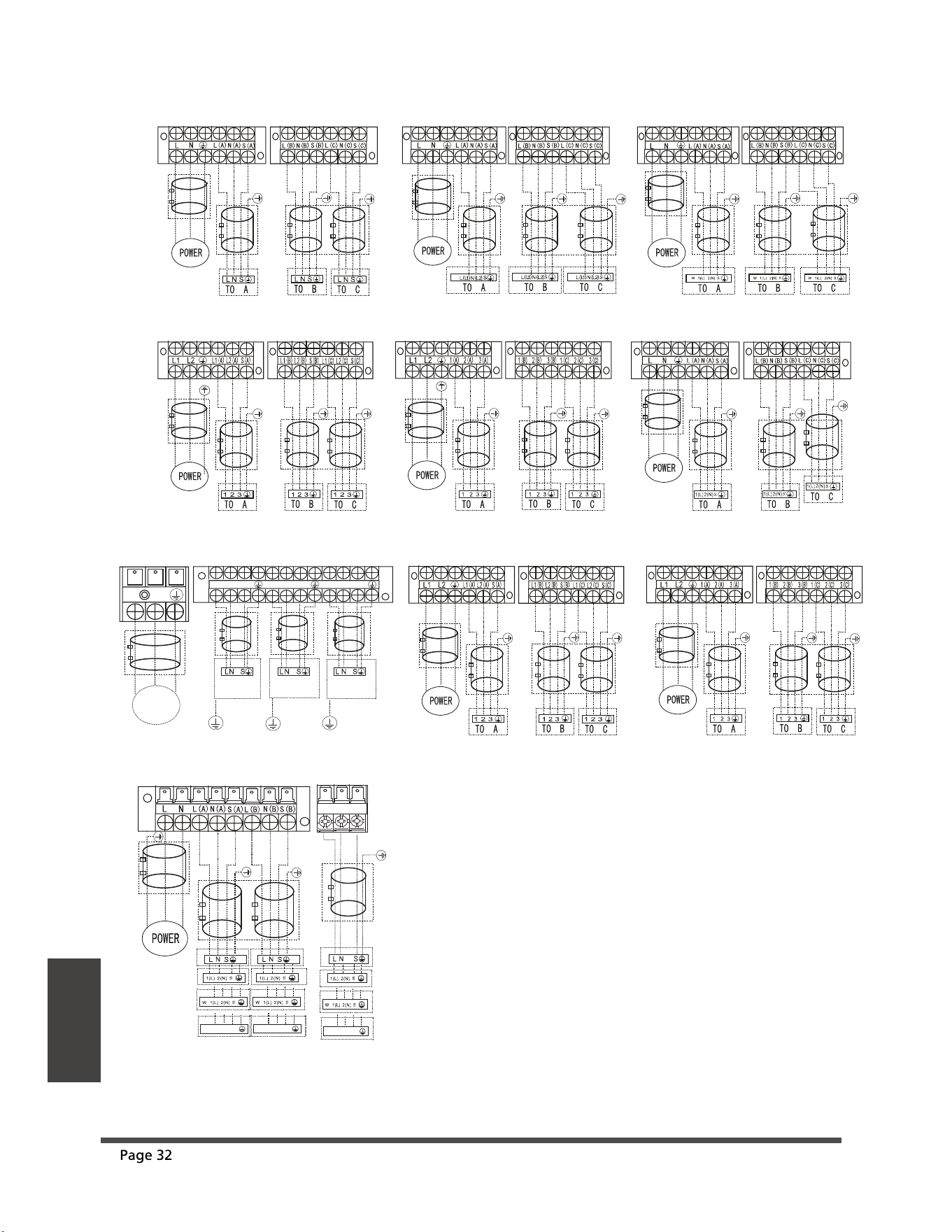
One-three models:
1(L) 2(N) 3(S)
1(L) 2(N) 3(S)
1(L) 2(N) 3(S)
Y/G
72%
72&
Y/G
L(A)
N(A)
S(A)
L(B)
N(B)
S(B)
L(C)
N(C)
S(C)
POWER
6833/<
N
L
Y/G
72$
Model A
Model B
Model C
Model D Model E
Model G
OPTIONAL
OPTIONAL
OPTIONAL
OPTIONAL
Model F
OPTIONAL
OPTIONAL
OPTIONAL
OPTIONAL
OPTIONAL
OPTIONAL
OPTIONAL
OPTIONAL
OPTIONAL
OPTIONAL
OPTIONAL
OPTIONAL
OPTIONAL
OPTIONAL
OPTIONAL
OPTIONAL
OPTIONAL
OPTIONAL
OPTIONAL
OPTIONAL
Model H Model I
OPTIONAL
OPTIONAL
OPTIONAL
OPTIONAL
OPTIONAL
OPTIONAL
OPTIONAL
OPTIONAL
OPTIONAL
OPTIONAL
OPTIONAL
OPTIONAL
ef
L(C) N(C) S(C)
OPTIONAL
or
or
To indoor
unit C
OPTIONAL
Model J
OPTIONAL
OPTIONAL
To indoor
unit A
To indoor
unit B
or
or
or
or
Wiring
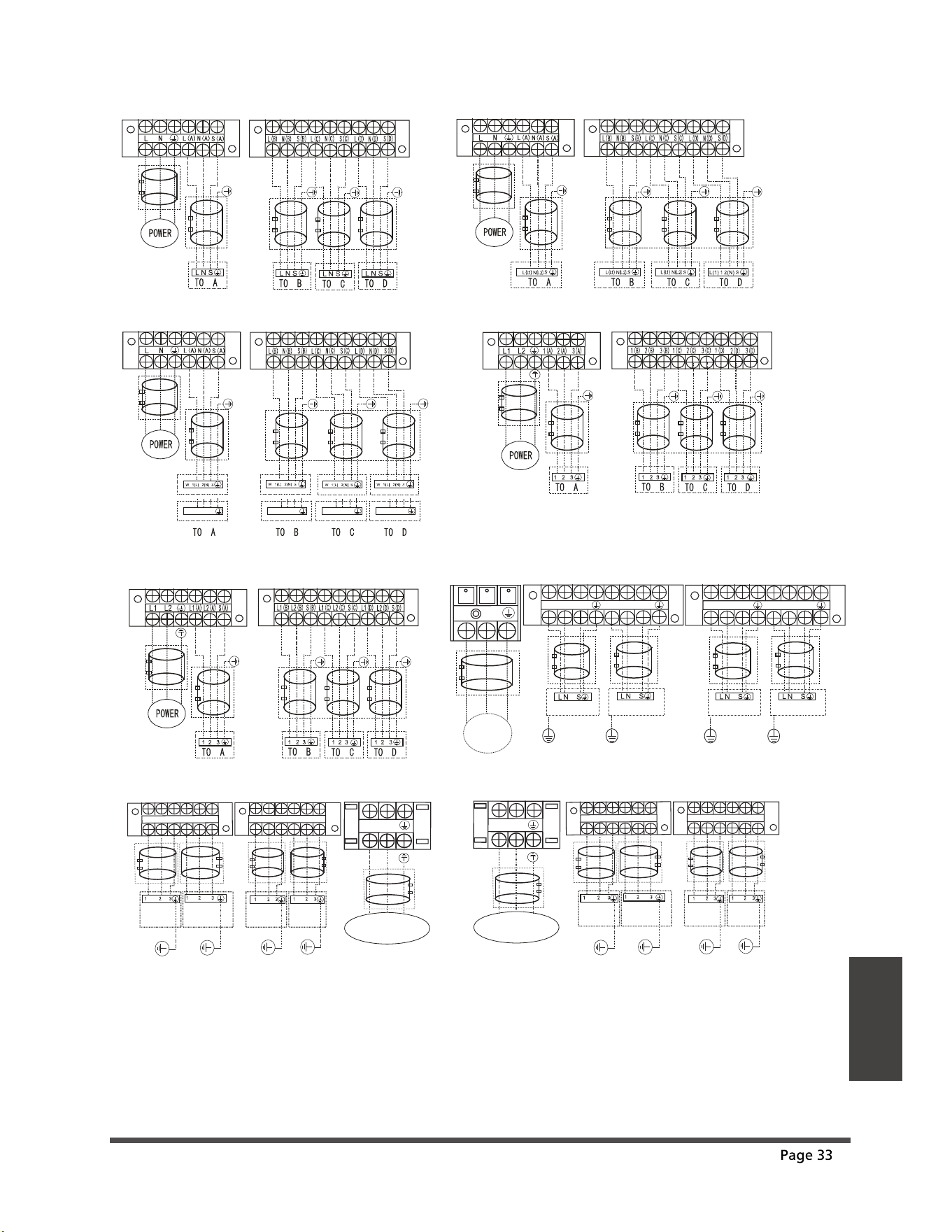
One-four models:
Y/G
72%
L(A)
N(A)
S(A)
L(B)
N(B)
S(B)
POWER
6833/<
N
L
Y/G
72$
Y/G
72%
L(C)
N(C)
S(C)
L(D)
N(D)
S(D)
Y/G
72$
Model A Model B
Model C
Model D
Model E Model F
OPTIONAL
OPTIONAL
OPTIONAL
OPTIONAL
OPTIONAL
OPTIONAL
OPTIONAL
OPTIONAL
OPTIONAL
OPTIONAL
OPTIONAL
OPTIONAL
OPTIONAL
OPTIONAL
OPTIONAL
OPTIONAL
OPTIONAL
OPTIONAL
OPTIONAL
OPTIONAL
OPTIONAL
OPTIONAL
OPTIONAL
OPTIONAL
OPTIONAL
OPTIONAL
OPTIONAL
OPTIONAL
OPTIONAL
OPTIONAL
Model G
L2
L1
LPPU
S REWO
PY
1(A)
2(A)
3(A)
1(B)
2(B)
3(B)
1(C)
2(C)
3(C)
1(D)
2(D)
3(D)
TO A
TO B
TO D
TO C
OPTIONAL
OPTIONAL
OPTIONAL
OPTIONAL
OPTIONAL
Model H
L2
L1
LPPU
S R
EWO
PY
L1(A)
L2(A)
S(A)
L1(B)
L2(B)
S(B)
L1(C) L2(C) S(C) L1(D)L2(D)S(D)
TO A
TO B
TO D
TO C
OPTIONAL
OPTIONAL
OPTIONAL
OPTIONAL
OPTIONAL
ef
or or
1(L) 2(N) 3(S) 1(L) 2(N) 3(S) 1(L) 2(N) 3(S) 1(L) 2(N) 3(S)
Mode K
OPTIONAL
OPTIONAL
OPTIONAL
OPTIONAL
OPTIONAL
Model L
OPTIONAL
OPTIONAL
OPTIONAL
OPTIONAL
OPTIONAL
L1(C) L2(C) S(C) L1(D)L2(D)S(D)
Model I
L2
L1
LPP
US REWOPY
1(A)
2(A)
3(A)
1(B)
2(B)
3(B)
1(C)
2(C)
3(C)
1(D)
2(D)
3(D)
TO A
TO B
TO D
TO C
OPTIONAL
OPTIONAL
OPTIONAL
OPTIONAL
OPTIONAL
Model J
L2
L1
LP
P
US REWOPY
L1(A)
L2(A)
S(A)
L1(B)
L2(B)
S(B)
TO A
TO B
TO D
TO C
OPTIONAL
OPTIONAL
OPTIONAL
OPTIONAL
OPTIONAL
Wiring
ef
L(C)
S(C)
N(C)
L(D)
N(D)
S(D)
OPTIONAL
OPTIONAL
OPTIONAL
Model M
OPTIONAL
OPTIONAL
To indoor
unit A
To indoor
unit B
or
or
or
or
To indoor
unit C
To indoor
unit D
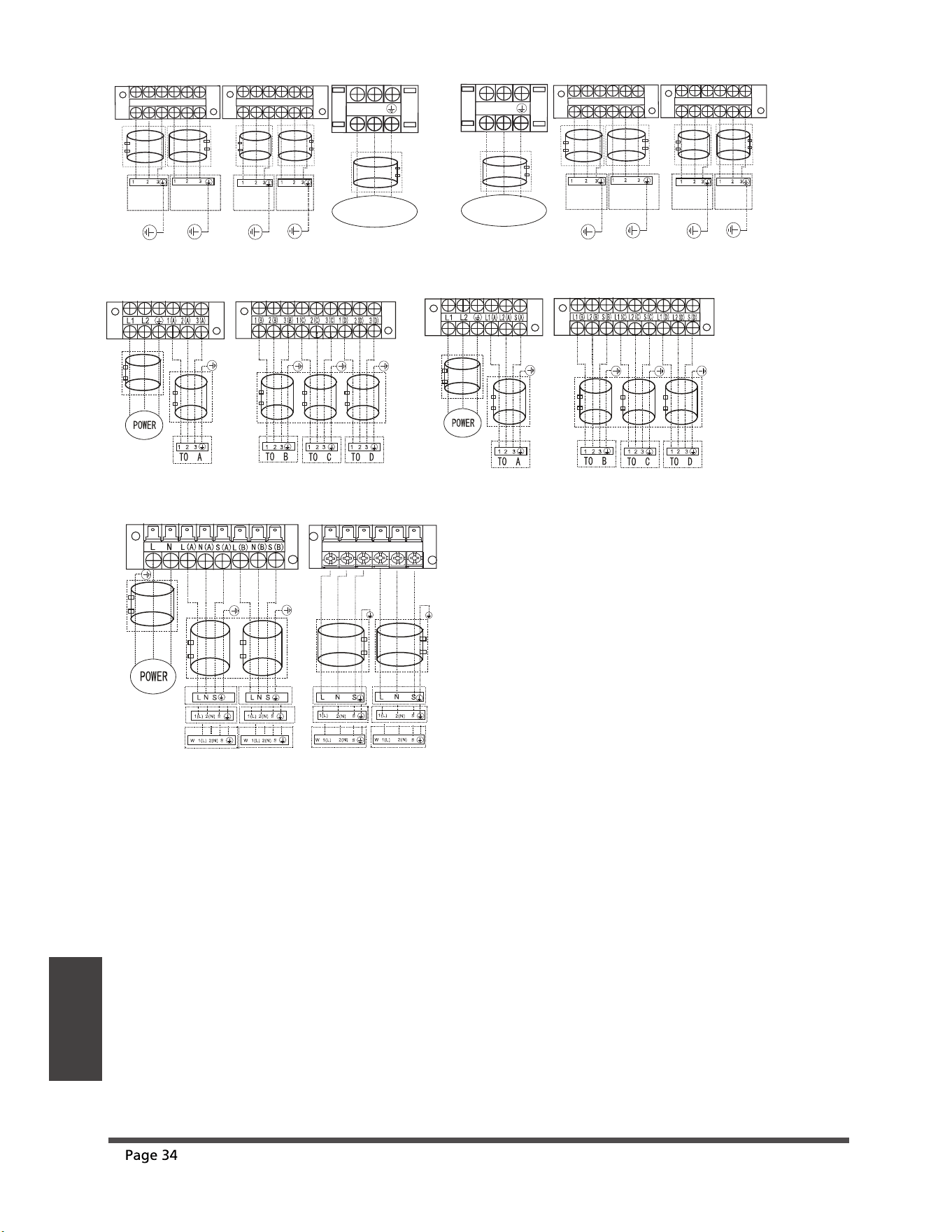
One-five models:
Model A
Model B
OPTIONAL
OPTIONAL
OPTIONAL
OPTIONAL
OPTIONAL
OPTIONAL
OPTIONAL
OPTIONAL
OPTIONAL
OPTIONAL
OPTIONAL
OPTIONAL
Wiring
Model G Model H
OPTIONAL
OPTIONAL
OPTIONAL
OPTIONAL
OPTIONAL
OPTIONAL
OPTIONAL
OPTIONAL
OPTIONAL
OPTIONAL
OPTIONAL
OPTIONAL
Model C Model D
OPTIONAL
OPTIONAL
OPTIONAL
OPTIONAL
OPTIONAL
OPTIONAL
OPTIONAL
OPTIONAL
OPTIONAL
OPTIONAL
OPTIONAL
OPTIONAL
Model E
L2
L1
LPP
US R
E
WOPY
1(A)
2(A)
3(A)
1(B)
2(B)
3(B)
1(C)
2(C)
3(C)
1(D)
2(D)
3(D)
1(E)
2(E)
3(E)
TO A
TO B
TO D
TO E
TO C
OPTIONAL
OPTIONAL
OPTIONAL
OPTIONAL
OPTIONAL
OPTIONAL
OPTIONAL
Model F
L(C)
N(C)
S(C)
L(D)
N(D)
S(D)
L(E)
N(E)
S(E)
TO D
TO E
TO C
L(A)
N(A)
S(A)
L(B)
N(B)
S(B)
TO A
TO B
OPTIONAL
OPTIONAL
OPTIONAL
OPTIONAL
N
L
LPPUS RE
WOP
Y
OPTIONAL
ef
or
or
1(L) 2(N) 3(S) 1(L) 2(N) 3(S)
1(L) 2(N) 3(S)
1(L) 2(N) 3(S)
1(L) 2(N) 3(S)
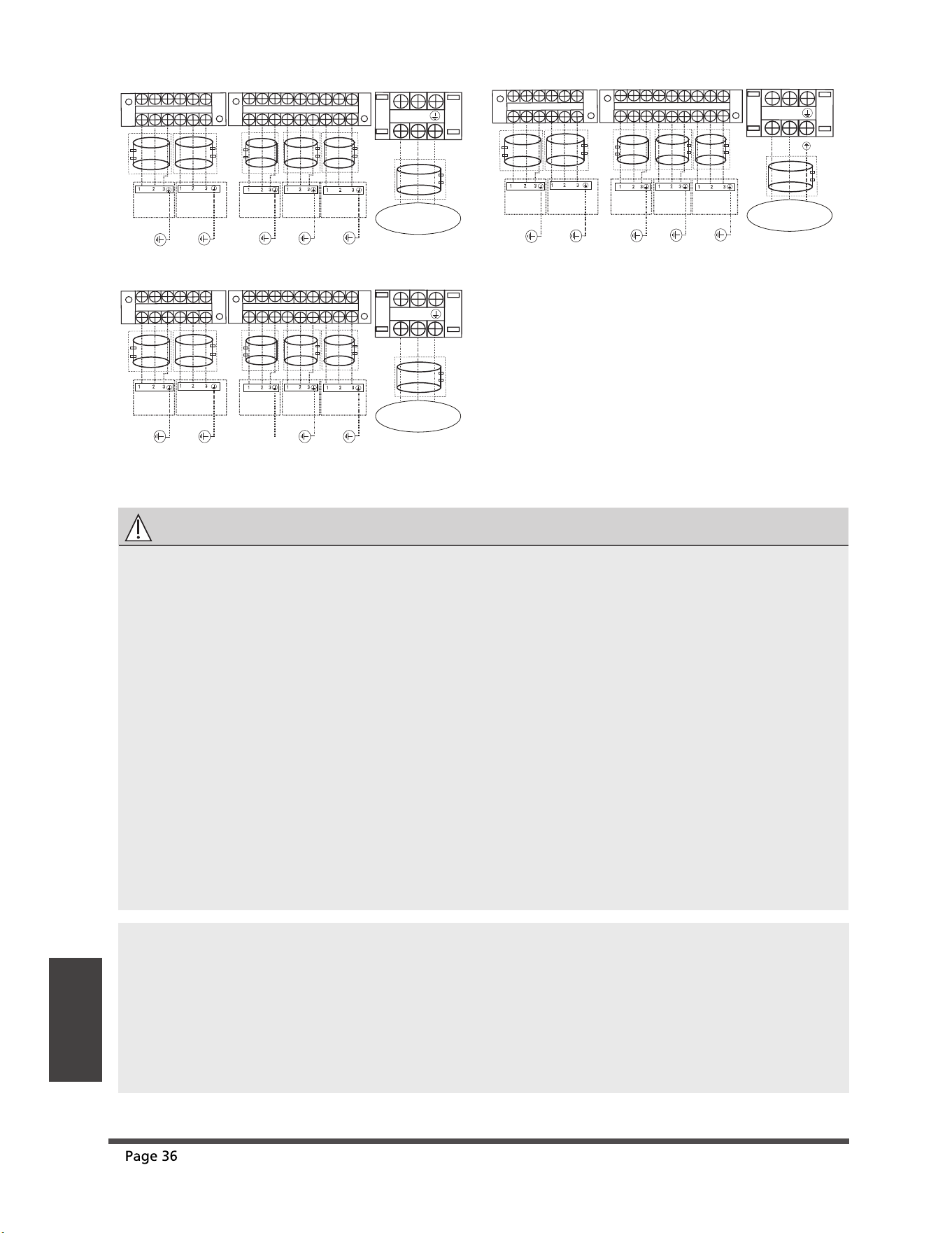
CAUTION
After conrmation of the above conditions, follow these guidelines when performing wiring:
• Always have an individual power circuit specically for the air conditioner. Always follow
the circuit diagram posted on the inside of the control cover.
•
• Check the specications for the power source.
• Conrm that electrical capacity is sucient.
• Conrm that the cable thickness is as specied in the power source specications.
• Always install an earth leakage circuit breaker in wet or moist areas.
Screws fastening the wiring in the casing of electrical ttings may come loose during
transporation. Because loose screws may cause wire burn-ou, check that the screws are
tightly fastened.
• The following can be caused by a drop in voltage: vibration of a magnetic switch,
damaging the contact point, broken fuses, and disturbance of normal functioning.
• Conrm that starting voltage is maintained at more than 90 percent of the rated voltage
marked on the name plate.
• Before accessing terminals, all supply circuits must be disconnected.
• Disconnection from a power supply must be incorporated into the xed wiring. It must
have an air gap contact separation of at least 3mm in each active (phase) conductors.
NOTE:
To satisfy the EMC compulsory regulations, which is required by the international standard
CISPR 14-1:2005/A2:2011 in specic countries or districts ,please make sure you apply the
correct magnetic rings on your equipment according to the wiring diagram that adhere to
the your equipment .
Please contact your distributor or installer to get further information and purchase
magnetic rings (The supplier of magnetic ring is TDK(model ZCAT3035-1330)or similar) .
Model I
L2
L1
LP
PUS
REWOPY
1(A)
2(A)
3(A)
1(B)
2(B)
3(B)
1(C)
2(C)
3(C)
1(D)
2(D)
3(D)
1(E)
2(E)
3(E)
TO A
TO B
TO D
TO E
TO C
OPTIONAL
OPTIONAL
OPTIONAL
OPTIONAL
OPTIONAL
OPTIONAL
Model K
L2
L1
LPPUS
REWOPY
L1(A)
L2(A)
S(A)
L1(B)
L2(B)
S(B)
L1(C)
L2(C)
S(C)
L1(D)
L2(D)
S(D)
L1(E)
L2(E)
S(E)
TO A
TO B
TO D
TO E
TO C
OPTIONAL
OPTIONAL
OPTIONAL
OPTIONAL
OPTIONAL
OPTIONAL
Model J
L2
L1
LP
PUS
R
E
WOPY
L1(A)
L2(A)
S(A)
L1(B)L
2(B)
S(B)
L1(C)
L2(C)
S(C)
L1(D)
L2(D)
S(D)
L1(E)
L2(E)
S(E)
TO A
TO B
TO D
TO E
TO C
OPTIONAL
OPTIONAL
OPTIONAL
OPTIONAL
OPTIONAL
OPTIONAL
Wiring
ef
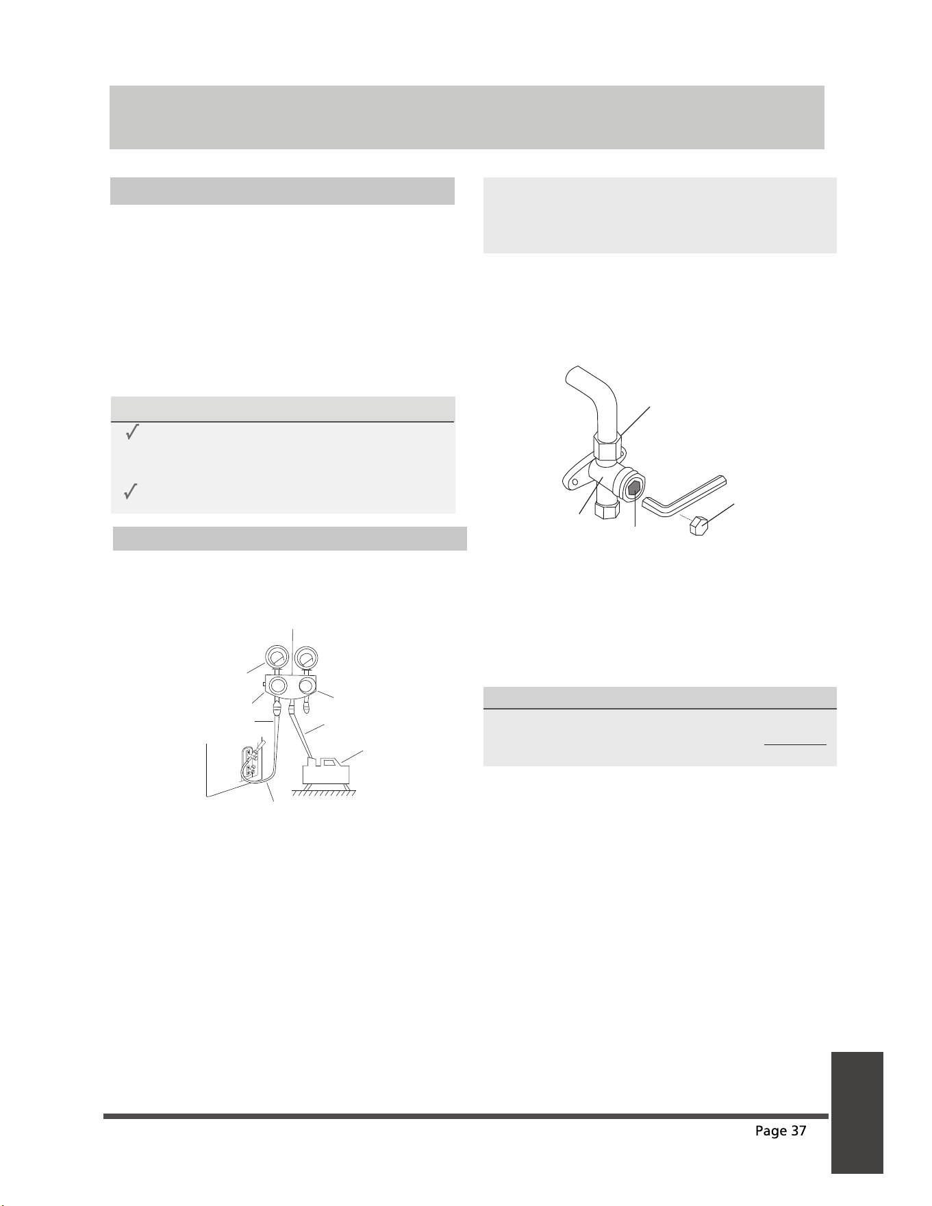
Evacuation Instructions
Before using a manifold gauge and a vacuum
pump, read their operation manuals to make
sure you know how to use them properly.
Manifold Gauge
Compound gauge
-76cmHg
Low pressure valve
High pressure valve
Charge hose
Charge hose
Vacuum pump
Pressure gauge
Low pressure valve
1. Connect the manifold gauge’s charge hose
to the service port on the outdoor unit’s low
pressure valve.
2. Connect the manifold gauge’s charge hose
from the to the vacuum pump.
3. Open the Low Pressure side of the manifold
gauge. Keep the High Pressure side closed.
4. Turn on the vacuum pump to evacuate the system.
5. Run the vacuum for at least 15 minutes, or until
the Compound Meter reads -76cmHG (-1x10⁵Pa).
6. Close the manifold gauge’s Low Pressure valve
and turn o the vacuum pump.
7. Wait for 5 minutes, then check that there has
been no change in system pressure.
NOTE: If there is no change in system pressure,
unscrew the cap from the packed valve (high
pressure valve). If there is a change in system
pressure, there may be a gas leak.
8. Insert hexagonal wrench into the packed valve
(high pressure valve) and open the valve by
turning the wrench 1/4 counterclockwise.
Listen for gas to exit the system, then close the
valve after 5 seconds.
Flare nut
Cap
Valve body
Valve stem
9. Watch the Pressure Gauge for one minute to make
sure that there is no change in pressure. It should
read slightly higher than the atmospheric pressure.
10.Remove the charge hose from the service port.
11. Using hexagonal wrench, fully open both the
high pressure and low pressure valves.
OPEN VALVE STEMS GENTLY
When opening valve stems, turn the hexagonal
wrench until it hits against the stopper. DO NOT
try to force the valve to open further.
12.Tighten valve caps by hand, then tighten it
using the proper tool.
13.If the outdoor unit uses all vacuum valves,
and the vacuum position is at the main valve,
the system is not connected with the indoor
unit. The valve must be tightened with a
screw nut. Check for gas leaks before
operation to prevent leakage.
Air Evacuation
Preparations and Precautions
Air and foreign matter in the refrigerant circuit can
cause abnormal rises in pressure, which can damage
the air conditioner, reduce its efficiency, and cause
injury. Use a vacuum pump and manifold gauge to
evacuate the refrigerant circuit, removing any
non-condensable gas and moisture from the system.
Evacuation should be performed upon initial
installation and when unit is relocated.
BEFORE PERFORMING EVACUATION
Check to make sure the connective pipes
between the indoor and outdoor units
are connected properly .
Check to make sure all wiring is connected
ef
Air Evacuation
Note On Adding Refrigerant
CAUTION
• Refrigerant charging must be performed after wiring, vacuuming, and the leak testing.
• DO NOT exceed the maximum allowable quantity of refrigerant or overcharge the system.
Doing so can damage the unit or impact it’s functioning.
• Charging with unsuitable substances may cause explosions or accidents. Ensure that the
appropriate refrigerant is used.
• For the R290 or R32 refrigerant model, make sure the condtions within the area have been
made safe by control of ammable material when the refrigerant added into air conditioner.
Refrigerant containers must be opened slowly. Always use protective gear when charging the
system.
•
• DO NOT mix refrigerants types.
ADDITIONAL REFRIGERANT PER PIPE LENGTH
Connective Pipe
Length(m)
Air Purging
Method
Additional Refrigerant
Pre-charge pipe length (ft/m)
(
pre-charge pipe length
xN )
Vacuum Pump
N/A
More than (
pre-charge
pipe length
xN) ft/m
Vacuum Pump
Liquid Side: Ø 6.35 (Ø 1/4”)
(Total pipe length - pre-charge pipe lengthxN) x12g/m
(Total pipe length - pre-charge pipe lengthxN) x0.13oZ/ft
Liquid Side: Ø 9.52 (Ø 3/8”)
R32 R32
R410A R410A
(Total pipe length - pre-charge pipe lengthxN) x24g/m
(Total pipe length - pre-charge pipe lengthxN) x0.26oZ/ft
Liquid Side: Ø 6.35 (Ø 1/4”)
(Total pipe length - pre-charge pipe lengthxN) x15g/m
(Total pipe length - pre-charge pipe lengthxN) x0.16oZ/ft
Liquid Side: Ø 9.52 (Ø 3/8”)
(Total pipe length - pre-charge pipe lengthxN) x30g/m
(Total pipe length - pre-charge pipe lengthxN) x0.32oZ/ft
The standard pipe length is 7.5m.
NOTE:
N=2(one-twin models), N=3(one-three models), N=4(one-four models), N=5(one-ve models).
Depending on the length of connective piping or the pressure of the evacuated system, you
made need to add refrigerant. Refer to table below for refrigerant amounts to be added:
Air Evacuation
ef
Air Evacuation
ADDITIONAL REFRIGERANT PER PIPE LENGTH
Connective Pipe
Length(m)
Air Purging
Method
Additional Refrigerant(R410A)
Less than
Standard pipe length x N
Vacuum Pump
N/A
More than
Standard pipe length x N
Vacuum Pump
Liquid Side: Ø 6.35 (Ø 1/4”)
(Total pipe length - pre-charge pipe lengthxN) x15g/m
Liquid Side: Ø 9.52 (Ø 3/8”)
(Total pipe length - pre-charge pipe lengthxN) x30g/m
Only for Australia models :
•
DO NOT
mix refrigerants types.
N=2(one-twin models),N=3(one-three models),N=4(one-four models),N=5(one-ve models).
Some systems require additional charging depending on pipe lengths. The standard pipe length
is 10m. The additional refrigerant to be charged can be calculated using the following formula:
Make sure to remove the additional refrigerant charge according to the rated volume (5m
refrigerant piping) when doing market or government verication test.
ef
Air Evacuation
Safety And Leakage Check
Electrical safety check
Perform the electrical safety check after
completing installation. Cover the following
areas:
1. Insulated resistance
The insulated resistance must be more
than 2MΩ.
2. Grounding work
After nishing grounding work, measure
the grounding resistance by visual detection
and using the grounding resistance tester.
Make sure the grounding resistance is less
than 4Ω.
3. Electrical leakage check (performing during
test while unit is on)
During a test operation after completed
installation, the use the electroprobe and
multimeter to perform an electrical leakage
check. Turn o the unit immediately if
leakage happens. Try and evaluate dierent
solutions until the unit operates properly.
Gas leak check
1. Soap water method:
Apply a soap-water solution or a liquid
neutral detergent on the indoor unit
connection or outdoor unit connections with
a soft brush to check for leakage of the
connecting points of the piping. If bubbles
emerge, the pipes are experiencing leakage.
2. Leak detector
Use the leak detector to check for leakage.
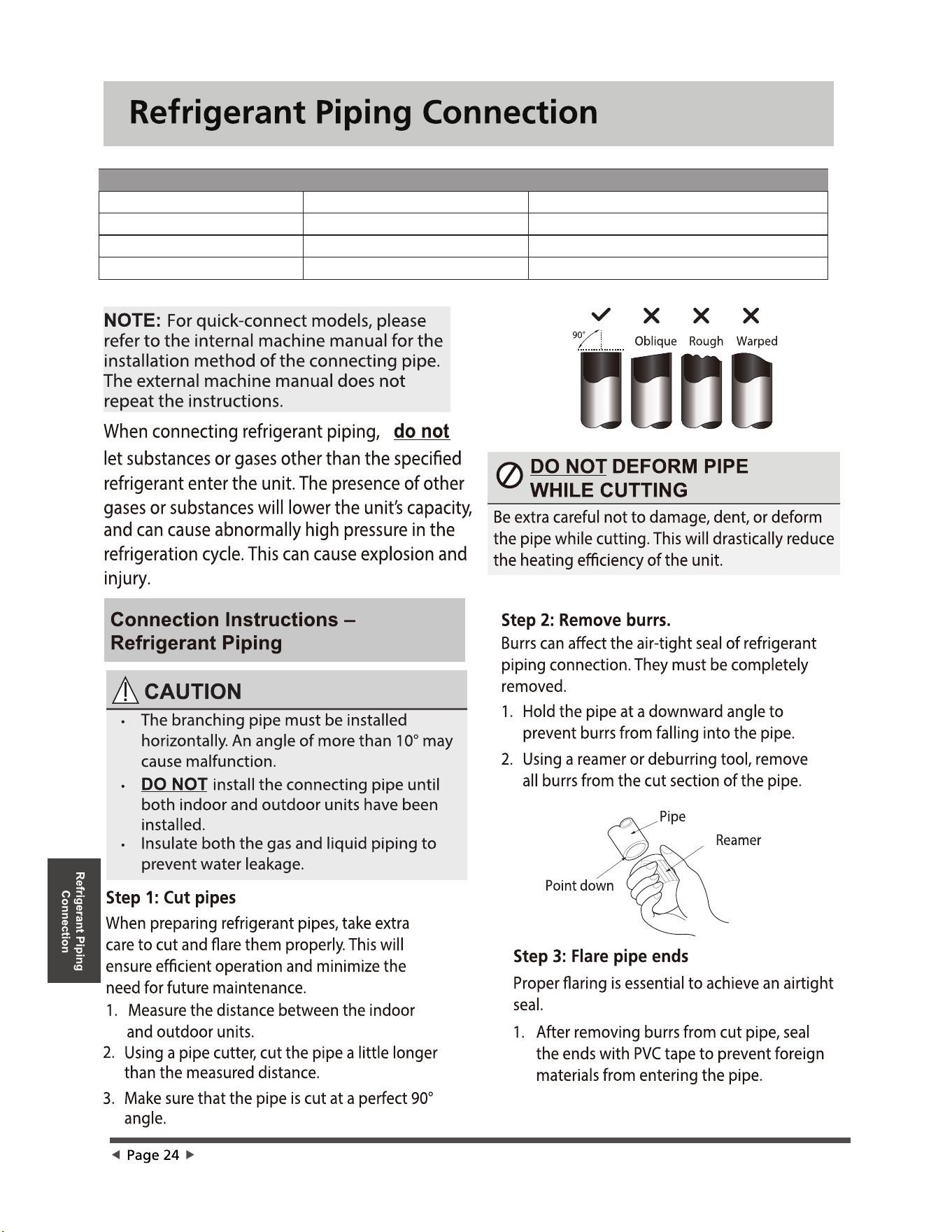
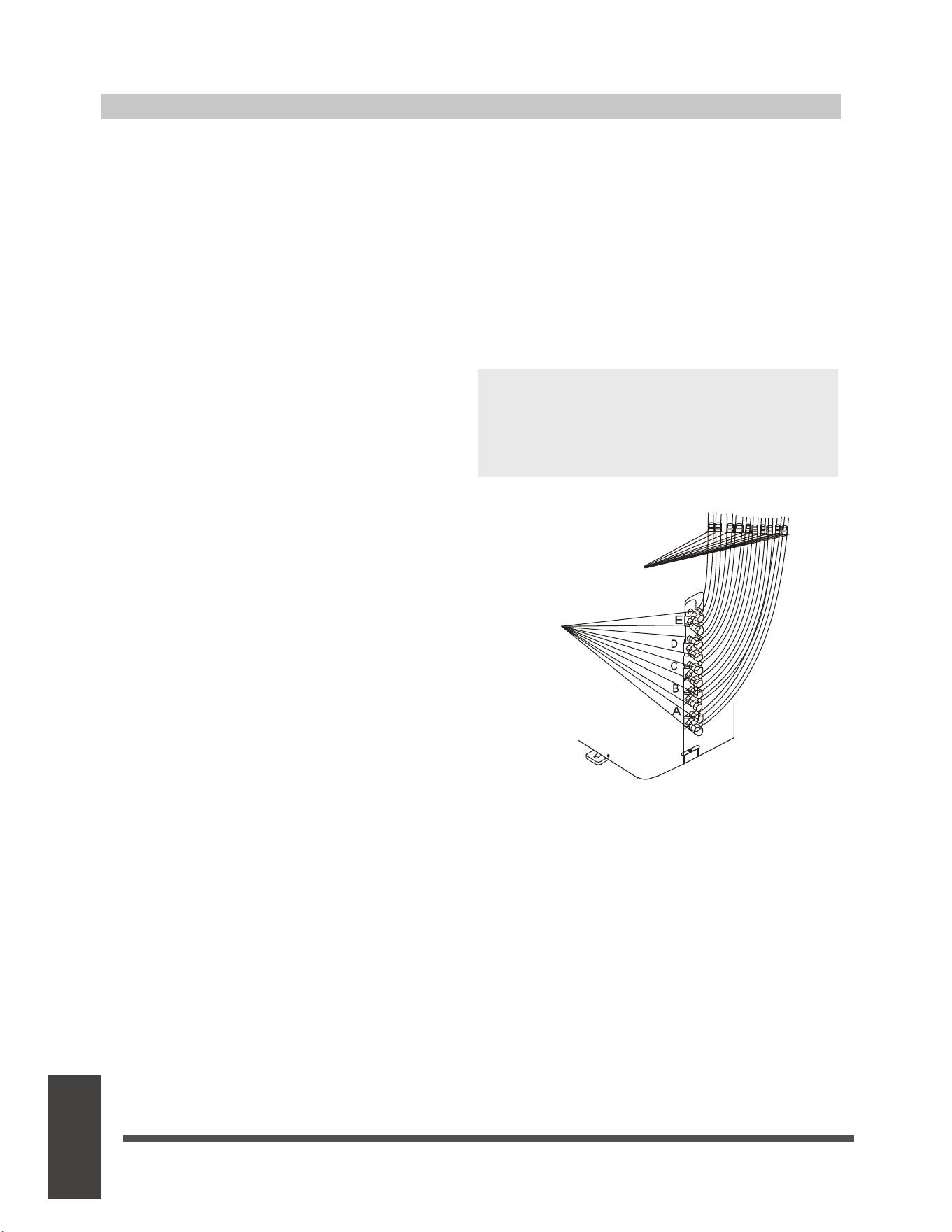
NOTE: The illustration is for example purposes
only. The actual order of A, B, C, D, and E on
the machine may be slightly dierent from the
unit you purchased but the general shape will
remain the same.
Indoor unit
check point
Outdoor unit
check point
A, B,C,D are points for one-four type.
A, B,C,D, and E are points for the one-ve type.
e
Page 40
f

Test Run
Before Test Run
A test run must be performed after the entire
system has been completely installed. Confirm
the following points before performing the test:
a) The indoor and outdoor units are properly
installed.
b) Piping and wiring are properly connected.
c) No obstacles near the inlet and outlet of the
unit that might cause poor performance or
product malfunction.
d) The refrigeration system does not leak.
e) Drainage system is unimpeded and draining
to a safe location.
f) The heating insulation is properly installed.
g) The grounding wires are properly connected.
h) Length of the piping and additional
refrigerant stow capacity have been recorded.
i) The power voltage is the correct voltage for
the air conditioner.
CAUTION
Failure to perform the test run may result in unit
damage, property damage or personal injury.
Test Run Instructions
1. Open both the liquid and gas stop valves.
2. Turn on the main power switch and allow the
unit to warm up.
3. Set the air conditioner to COOL mode.
4. For the Indoor Unit
a. Ensure the remote control and its buttons
work properly.
b. Ensure the louvers move properly and can
be changed using the remote control.
c. Double check to see if the room
temperature is being registered correctly.
d. Ensure the indicators on the remote control
and the display panel on the indoor unit
work properly.
e. Ensure the manual buttons on the indoor
unit works properly.
f. Check to see that the drainage system is
unimpeded and draining smoothly.
g. Ensure there is no vibration or abnormal
noise during operation.
5. For the Outdoor Unit
a. Check to see if the refrigeration system is
leaking.
b. Make sure there is no vibration or
abnormal noise during operation.
c. Ensure the wind, noise, and water
generated by the unit do not disturb your
neighbors or pose a safety hazard.
Test Run
NOTE: If the unit malfunctions or does not
operate according to your expectations,
please refer to the Troubleshooting section
of the Owner’s Manual before calling
customer service.
e
Page 41
f
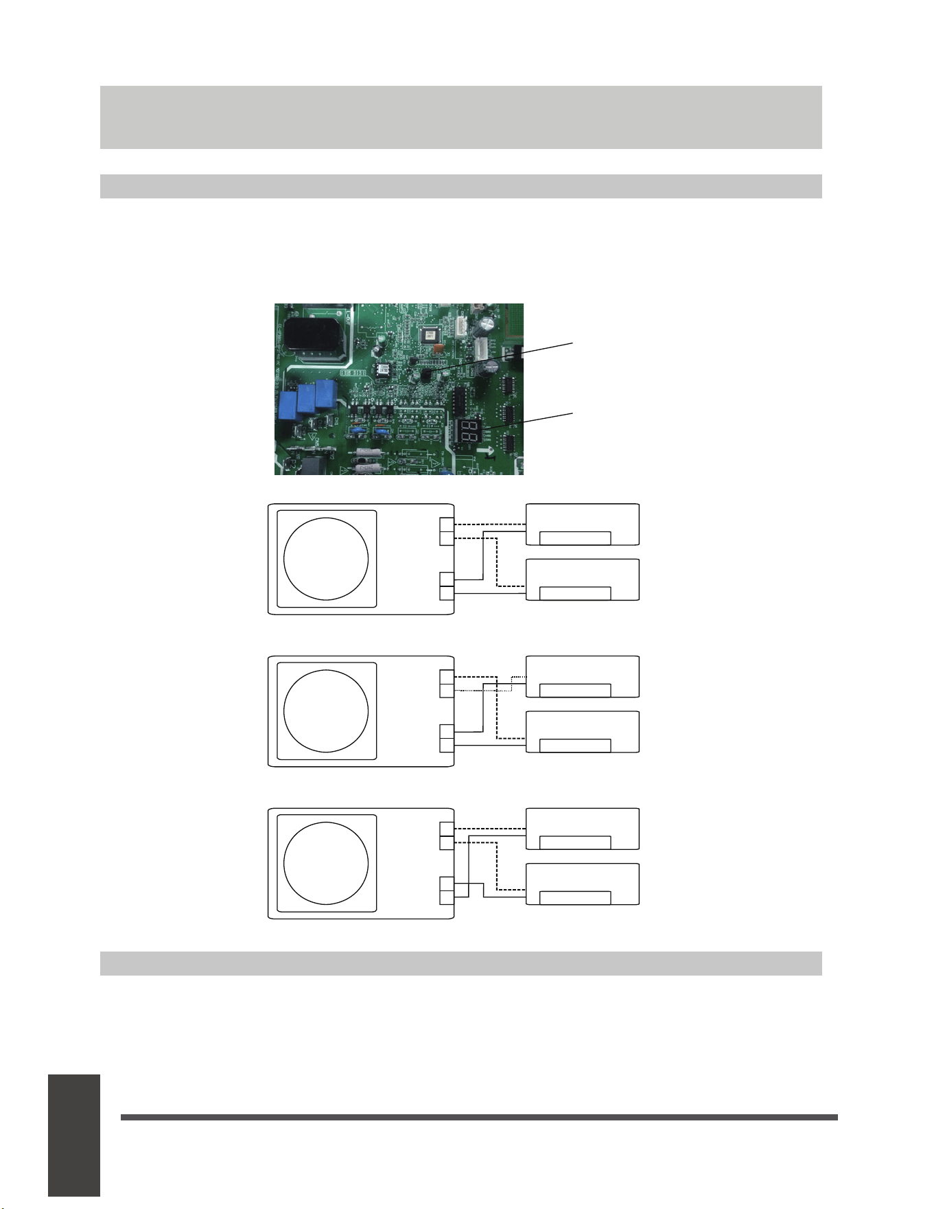
Automatic Wiring/Piping Correction Function
Function of Automatic Wiring/Piping Correction
Function of
Automatic Wiring/
Piping Correction
More recent models now feature automatic correction of wiring/piping errors. Press the "check
switch" on the outdoor unit PCB board for 5 seconds until the LED displays "CE”, indicatomg that
this function is working, Approximately 5-10 minutes after the switch is pressed, the "CE" disappears,
meaning that the wiring/piping error is corrected and all wiring/piping is properly connected.
How To Activate This Function
1. Check that outside temperature is above 5℃.
(This function does not work when outside temperature is not above 5℃)
2. Check that the stop valves of the liquid pipe and gas pipe are open.
3. Turn on the breaker and wait at least 2 minutes.
4. Press the check switch on the outdoor PCB board unit LED display "C E".
Correct
Terminal
block
Liquid/
Gas pipe
Outdoor unit
Indoor unit B
Indoor unit A
B
A
B
A
Incorrect wiring
Terminal
block
Liquid/
Gas pipe
Outdoor unit
Indoor unit B
Indoor unit A
B
A
B
A
Incorrect wiring
Terminal
block
Liquid/
Gas pipe
Outdoor unit
Indoor unit B
Indoor unit A
B
A
B
A
Check switch
LED display
e
Page 42
f


The design and specifications are subject to change without prior notice for
product improvement. Consult with the sales agency or manufacturer for details.
Any updates to the manual will be uploaded to the service website, please check
for the latest version.
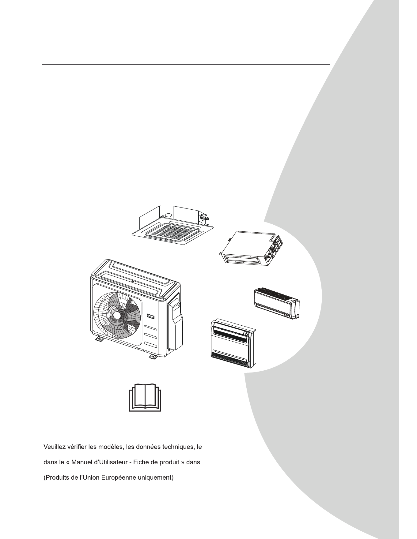
NOTE IMPORTANTE :
Lisez attentivement ce manuel avant d’installer ou
d’utiliser votre nouveau l’unité de climatisation. Veillez à
conserver ce manuel pour toute référence ultérieure.
gaz F-GAS et les informations du fabricant applicables
l’emballage de l’unité extérieure.
Manuel d'Utilisateur &
Manuel d’Installation
MHMZ Series
ONDULEUR D’UN-DEUX/UN-TROIS/UN-QUATRE/UN-CINQ
CLIMATISEUR DU TYPE SPLIT

Consignes GH sécurité ......................................................................04
Manuel d’Utilisateur
Pièces et Fonctions Principales de l’Unité Intérieure ....................08
3LqFHVGHO¶XQLWp ..................................................................................................................................................08
2. Température de fonctionnement .......................................................................................................................... 10
3. Fonctions ............................................................................................................................................................. 11
Opérations Manuelles et 0DLQWHQDQFH.............................................13
Dépannage .........................................................................................14
Table des Matières

Manuel d’Installation
Accessoires ................................................................................. 17
Résumé de l’installation ............................................................. 18
Schéma d’installation.................................................................. 19
Spéci¿cations .............................................................................. 20
Installation de l’unité extérieure................................................. 21
1. Sélectionnez l’emplacement de l’installation ............................................................................................. 21
2. Installez le joint de drainage ...................................................................................................................... 22
3. Fixez l’unité extérieure............................................................................................................................... 22
Raccordement de la Tuyauterie de Réfrigérant ........................ 24
1. Coupez des tuyaux .................................................................................................................................... 24
2. Enlevez les bavures .................................................................................................................................. 24
3. Évasez les extrémités des tuyaux ............................................................................................................. 24
4. Connectez les tuyaux ................................................................................................................................ 25
Câblage......................................................................................... 27
1. Câblage de l’unité extérieure ..................................................................................................................... 29
2. Figure du câblage .
.....................................................................................................................................
30
Évacuation d’air ........................................................................... 37
1. Note relative à l’ajout de réfrigérant........................................................................................................... 38
9pUL¿FDWLRQGHODVpFXULWpHWGHVIXLWHV ...................................................................................................... 40
Mise en service ............................................................................ 41
Fonction de la correction automatique
de câblage/tuyauterie42
Consignes de
Sécurité
Page 4
Consignes de Sécurité
Lisez les Consignes de Sécurité avant l’Utilisation et l’Installation
Une installation incorrecte en raison d’instructions non respectées peut causer de graves dommages ou
des blessures.
La gravité des dommages ou blessures potentiels est classée soit par AVERTISSEMENT ou
par
ATTENTION.
AVERTISSEMENT
&HV\PEROHLQGLTXHODSRVVLELOLWpGHEOHVVXUHVRX
de pertes de vie.
ATTENTION
&HV\PEROHLQGLTXHODSRVVLELOLWpGHGRPPDJHV
PDWpULHOVRXGHFRQVpTXHQFHVJUDYHV
AVERTISSEMENT
Le présent appareil peut être utilisé par des enfants âgés de 8 ans et plus et des personnes ayant des capacités
SK\VLTXHVVHQVRULHOOHVRXPHQWDOHVOLPLWpHVRXQHGLVSRVDQWSDVG¶H[SpULHQFHHWGHVDYRLUIDLUHV¶LOVRQW
reçu une supervision ou une instruction concernant l’utilisation de l’unité en toute sécurité en connaissant les
GDQJHUVLPSOLTXpV/HVHQIDQWVQHGRLYHQWSDVMRXHUDYHFO¶DSSDUHLO/HQHWWR\DJHHWODPDLQWHQDQFHSDUODSSDUHLO
ne doivent pas être effectués par des enfants sans surveillance.
&HWDSSDUHLOQ¶HVWSDVGHVWLQpjrWUHXWLOLVpSDUGHVSHUVRQQHV\FRPSULVGHVHQIDQWVD\DQWGHVFDSDFLWpV
SK\VLTXHVRXPHQWDOHVSK\VLTXHVRXPHQWDOHVUpGXLWHVRXPDQTXDQWG¶H[SpULHQFHHWGHFRQQDLVVDQFHVj
PRLQVTX¶XQHSHUVRQQHUHVSRQVDEOHGHOHXUVpFXULWpQHOHVDLWVXSHUYLVpHVRXLQVWUXLWHV/HVHQIDQWVGRLYHQW
rWUHVXUYHLOOpVSRXUV¶DVVXUHUTX¶LOVQHMRXHQWSDVDYHFOXQLWp
AVERTISSEMENTS POUR L’UTILISATION DU PRODUIT
• (QFDVGHVLWXDWLRQDQRUPDOHFRPPHXQHRGHXUGHEUOXUHYHXLOOH]pWHLQGUHLPPpGLDWHPHQWO¶XQLWpHW
GpEUDQFKHUO¶DOLPHQWDWLRQ$SSHOH]YRWUHUHYHQGHXUSRXUGHVLQVWUXFWLRQVD¿QG¶pYLWHUOHFKRFpOHFWULTXH
l’incendie ou les blessures.
• Ne pasLQVpUHUOHVGRLJWVOHVWLJHVRXDXWUHVREMHWVGDQVO¶HQWUpHRXODVRUWLHG¶DLU&HODSHXWSURYRTXHUGHV
EOHVVXUHVFDUOHYHQWLODWHXUSHXWWRXUQHUjJUDQGHYLWHVVH
• Ne pasXWLOLVHUGHVSUD\VLQÀDPPDEOHVWHOVTXHODODTXHSRXUOHVFKHYHX[ODODTXHRXODSHLQWXUHSUqVGH
O¶XQLWp&HODSHXWSURYRTXHUXQLQFHQGLHRXXQHFRPEXVWLRQ
• Ne pas faire fonctionner le climatiseur à proximité ou autour des gaz combustibles. Les gaz émis peuvent
V¶DFFXPXOHUDXWRXUGHO¶XQLWpHWSURYRTXHUXQHH[SORVLRQ
• Ne pas faireIRQFWLRQQHUOHFOLPDWLVHXUGDQVXQHSLqFHKXPLGHWHOOHTX¶XQHVDOOHGHEDLQRXXQHEXDQGHULH
8QHH[SRVLWLRQH[FHVVLYHjO¶HDXSHXWSURYRTXHUXQFRXUWFLUFXLWGHVFRPSRVDQWVpOHFWULTXHV
• Ne pas exposer votre corps directement à l’air frais pendant une période de temps prolongée.
• Ne pas laisser les enfants jouer autour du climatiseur. Les enfants doivent être surveillés tout autour de
l’unité.
• 6LOHFOLPDWLVHXUHVWXWLOLVpDYHFGHVEUOHXUVRXG¶DXWUHVXQLWpVGHFKDXIIDJHDpUH]HQWLqUHPHQWODSLqFH
SRXUpYLWHUXQHFDUHQFHHQR[\JqQH
• 'DQVFHUWDLQVHQYLURQQHPHQWVIRQFWLRQQHOVWHOVTXHOHVFXLVLQHVOHVVDOOHVGHVHUYHXUVHWFO¶XWLOLVDWLRQ
d’unités de climatisation spécialement conçues est fortement recommandée.
AVERTISSEMENTS DE NETTOYAGE ET DE MAINTENANCE
• eWHLJQH]OHGLVSRVLWLIHWGpEUDQFKH]O¶DOLPHQWDWLRQDYDQWOHQHWWR\DJH/DQpJOLJHQFHGHFHWWHRSpUDWLRQSHXW
SURYRTXHUXQFKRFpOHFWULTXH
• Ne pasQHWWR\HUOHFOLPDWLVHXUDYHFGHVTXDQWLWpVH[FHVVLYHVG¶HDX
Consignes de
Sécurité
AVERTISSEMENTS DE NETTOYAGE ET DE MAINTENANCE
• Ne pasQHWWR\HUOHFOLPDWLVHXUDYHFGHVSURGXLWVGHQHWWR\DJHLQÀDPPDEOHV/HVSURGXLWVGHQHWWR\DJH
FRPEXVWLEOHVSHXYHQWSURYRTXHUXQLQFHQGLHRXXQHGpIRUPDWLRQ
ATTENTION
• eWHLJQH]OHFOLPDWLVHXUHWGpEUDQFKH]O¶DOLPHQWDWLRQVLYRXVQHO¶XWLOLVH]SDVSHQGDQWXQHORQJXHSpULRGH
• eWHLJQH]HWGpEUDQFKH]O¶XQLWpSHQGDQWOHVWHPSrWHV
• $VVXUH]YRXVTXHODFRQGHQVDWLRQGHO¶HDXSXLVVHV¶pFRXOHUVDQVHQWUDYHGHO¶XQLWp
• Ne pasIDLUHIRQFWLRQQHUOHFOLPDWLVHXUDYHFOHVPDLQVPRXLOOpHV&HODSHXWSURYRTXHUXQFKRFpOHFWULTXH
• Ne pasXWLOLVHUO¶DSSDUHLOjG¶DXWUHV¿QVTXHO¶XWLOLVDWLRQSUpYXH
• Ne pas monter sur ou placer des objets sur le dessus de l’unité extérieure.
• Ne pas laisser le climatiseur fonctionner pendant de longues périodes avec des portes ou des fenêtres
RXYHUWHVRXORUVTXHO¶KXPLGLWpHVWWUqVpOHYpH
AVERTISSEMENTS ÉLECTRIQUES
• 8WLOLVH]XQLTXHPHQWOHFkEOHG¶DOLPHQWDWLRQVSpFL¿p6LOHFkEOHG¶DOLPHQWDWLRQHVWHQGRPPDJpFHFkEOHGRLW
rWUHUHPSODFpSDUOHIDEULFDQWVRQDJHQWGHVHUYLFHRXGHVSHUVRQQHVGHTXDOL¿FDWLRQVLPLODLUHSRXUpYLWHUWRXW
ULVTXH
• *DUGH]OD¿FKHG¶DOLPHQWDWLRQSURSUH(QOHYH]WRXWHODSRXVVLqUHRXODVDOHWpV¶DFFXPXODQWVXURXDXWRXUGHOD
¿FKH'HV¿FKHVVDOHVSHXYHQWSURYRTXHUXQLQFHQGLHRXXQFKRFpOHFWULTXH
• Ne pasWLUHUOHFkEOHG¶DOLPHQWDWLRQSRXUGpEUDQFKHUO¶XQLWp7HQLUIHUPHPHQWOD¿FKHHWUHWLUHUODGHODSULVH/H
WLUDJHGLUHFWVXUOHFkEOHSHXWO¶HQGRPPDJHUHWSURYRTXHUXQLQFHQGLHRXXQFKRFpOHFWULTXH
• Ne pasPRGL¿HUODORQJXHXUGXFkEOHG¶DOLPHQWDWLRQRXXWLOLVHUXQFkEOHGHUDOORQJHSRXUDOLPHQWHUO¶XQLWp
• Ne pasSDUWDJHUODSULVHpOHFWULTXHDYHFG¶DXWUHVDSSDUHLOV$OLPHQWDWLRQLQFRUUHFWHRXLQVXI¿VDQWHSHXW
SURYRTXHUXQLQFHQGLHRXXQFKRFpOHFWULTXH
• /HSURGXLWGRLWrWUHPLVjODWHUUHDXPRPHQWGHO¶LQVWDOODWLRQVLQRQOHFKRFpOHFWULTXHSHXWrWUHVHSURGXLUH
• 3RXUWRXVOHVWUDYDX[pOHFWULTXHVVXLYUHWRXWHVOHVQRUPHVGHFkEODJHORFDOHVHWQDWLRQDOHVOHV
réglementations et le manuel d’installation. Connectez les câbles étroitement et les serrez fermement pour
pYLWHUTXHGHVIRUFHVH[WHUQHVQ¶HQGRPPDJHQWOHWHUPLQDO'HVFRQQH[LRQVpOHFWULTXHVLQFRUUHFWHVSHXYHQW
VXUFKDXIIHUHWSURYRTXHUXQLQFHQGLHDLQVLTXHGHVFKRFV7RXVOHVUDFFRUGHPHQWVpOHFWULTXHVGRLYHQWrWUH
HIIHFWXpVFRQIRUPpPHQWDXVFKpPDGHUDFFRUGHPHQWpOHFWULTXHVLWXpVXUOHVSDQQHDX[GHVXQLWpVLQWpULHXUHV
et extérieures.
• 7RXWOHFkEODJHGRLWrWUHFRUUHFWHPHQWGLVSRVpSRXUTXHOHFRXYHUFOHGXSDQQHDXGHFRPPDQGHSXLVVHVH
IHUPHUFRUUHFWHPHQW6LOHFRXYHUFOHGXSDQQHDXGHFRPPDQGHQ¶HVWSDVFRUUHFWHPHQWIHUPpFHODSHXW
HQWUDvQHUGHODFRUURVLRQHWSURYRTXHUOHVSRLQWVGHFRQQH[LRQVXUODERUQHjFKDXIIHUV¶HQÀDPPHURX
SURYRTXHUXQFKRFpOHFWULTXH
• 6LYRXVUDFFRUGH]O¶DOLPHQWDWLRQjXQFkEODJH¿[HXQGLVSRVLWLIGHGpFRQQH[LRQRPQLSRODLUHD\DQWDXPRLQV
PPG¶HVSDFHPHQWGDQVWRXVOHVS{OHVHWXQFRXUDQWGHIXLWHSRXYDQWGpSDVVHUP$OHGLVSRVLWLIjFRXUDQW
GLIIpUHQWLHOUpVLGXHOD\DQWXQFRXUDQWGHIRQFWLRQQHPHQWUpVLGXHOQRPLQDOQHGpSDVVDQWSDVP$HWOD
GpFRQQH[LRQGRLWrWUHLQWpJUpHDXFkEODJH¿[HFRQIRUPpPHQWDX[UqJOHVGHFkEODJH
PRENDRE NOTE DES SPÉCIFICATIONS DU FUSIBLE
La carte de circuit imprimé du climatiseur est conçue avec un fusible pour fournir une protection contre les
surintensités.
/HVVSpFL¿FDWLRQVGXIXVLEOHVRQWLPSULPpHVVXUOHFLUFXLWLPSULPpWHOOHVTXH
7$9$&SRXU%WXK7$9$&SRXU!%WXK
NOTE :
3RXUOHVXQLWpVDYHFOHUpIULJpUDQW5RX5VHXOOHIXVLEOHHQFpUDPLTXHUpVLVWDQW
aux explosions peut être utilisé.
AVERTISSEMENTS POUR L’INSTALLATION DU PRODUIT
1. L’installation doit être effectuée par un revendeur agréé ou un spécialiste. Une installation défectueuse peut
SURYRTXHUXQHIXLWHG¶HDXXQFKRFpOHFWULTXHRXXQLQFHQGLH
Page 5

Consignes de
Sécurité
AVERTISSEMENTS POUR L’INSTALLATION DU PRODUIT
2. L’installation doit être effectuée conformément aux instructions d’installation. Une installation incorrecte peut
SURYRTXHUXQHIXLWHG¶HDXXQFKRFpOHFWULTXHRXXQLQFHQGLH
(Q$PpULTXHGX1RUGO¶LQVWDOODWLRQGRLWrWUHXQLTXHPHQWHIIHFWXpHFRQIRUPpPHQWDX[H[LJHQFHVGH1(&HW
&(&SDUXQSHUVRQQHODXWRULVp
3. &RQWDFWH]XQWHFKQLFLHQGHVHUYLFHDXWRULVpSRXUODUpSDUDWLRQRXODPDLQWHQDQFHGXSUpVHQWXQLWp/DSSDUHLO
doit être installé conformément aux réglementations de câblage nationales.
4. 8WLOLVH]XQLTXHPHQWOHVDFFHVVRLUHVHWOHVSLqFHVIRXUQLVDLQVLTXHOHVRXWLOVVSpFL¿pVSRXUO¶LQVWDOODWLRQ
/¶XWLOLVDWLRQGHSLqFHQRQVWDQGDUGSHXWSURYRTXHUGHVIXLWHVG¶HDXGHVFKRFVpOHFWULTXHVGHVLQFHQGLHVHW
des dommages à l’unité.
5. ,QVWDOOH]O¶XQLWpGDQVXQHPSODFHPHQWIHUPHpWDQWFDSDEOHGHVXSSRUWHUVRQSRLGV6LO¶HPSODFHPHQWFKRLVLQH
SHXWSDVVXSSRUWHUOHSRLGVGHO¶XQLWpRXVLO¶LQVWDOODWLRQQ¶HVWSDVHIIHFWXpHFRUUHFWHPHQWO¶XQLWpSHXWWRPEHU
et subir des blessures graves et des dommages.
6. ,QVWDOOH]ODWX\DXWHULHGHGUDLQDJHFRQIRUPpPHQWDX[LQVWUXFWLRQVGHFHPDQXHO8QGUDLQDJHLQVXI¿VDQWSHXW
SURYRTXHUGHVGpJkWVG¶HDXjYRWUHPDLVRQHWYRVELHQV
7. 3RXUOHVXQLWpVpTXLSpHVG¶XQFKDXIIDJHpOHFWULTXHDX[LOLDLUHne pasLQVWDOOHUO¶XQLWpjPRLQVGHPqWUH
SLHGVGHWRXWPDWpULDXFRPEXVWLEOH
8. NE PAS installer l’unité dans un endroit pouvant être exposé à fuite des gaz combustibles. Si le gaz combustible
V¶DFFXPXOHDXWRXUGHO¶XQLWpFHODSHXWSURYRTXHUO¶LQFHQGLH
9. ,OQHIDXWSDVGpPDUUHUO¶XQLWpTXHORUVTXHWRXVOHVWUDYDX[VRQWWHUPLQpV
10. /RUVGXGpSODFHPHQWGHFOLPDWLVHXUFRQVXOWH]GHVWHFKQLFLHQVGHVHUYLFHH[SpULPHQWpVSRXUOHGpEUDQFKHU
et le réinstaller.
11. 3RXULQVWDOOHUO¶XQLWpVXUVRQVXSSRUWYHXLOOH]OLUHOHVLQIRUPDWLRQVSRXUSOXVGHGpWDLOVGDQVOHVVHFWLRQV
©,QVWDOODWLRQGHO¶XQLWpLQWpULHXUHªHW©,QVWDOODWLRQGHO¶XQLWpH[WpULHXUHª
Remarque sur les gaz Àuorés non applicable j l’unité utilisant le réfrigérant R290
1. &HFOLPDWLVHXUFRQWLHQWGHVJD]GHVHUUHÀXRUpV3RXUGHVLQIRUPDWLRQVVSpFL¿TXHVVXUOHW\SHGHJD]HWOD
TXDQWLWpYHXLOOH]YRXVUHSRUWHUjO¶pWLTXHWWHDSSURSULpHVXUO¶XQLWpRXDX©0DQXHOG¶8WLOLVDWHXU)LFKHGH
SURGXLWªGDQVO¶HPEDOODJHGHO¶XQLWpH[WpULHXUH3URGXLWVXQLTXHPHQWGHO¶8QLRQ(XURSpHQQH
2. /¶LQVWDOODWLRQOHVHUYLFHODPDLQWHQDQFHHWODUpSDUDWLRQGXSUpVHQWXQLWpGRLYHQWrWUHHIIHFWXpVSDUXQ
WHFKQLFLHQFHUWL¿p
3. /HGpPRQWDJHHWOHUHF\FODJHGXSURGXLWGRLYHQWrWUHHIIHFWXpVSDUXQWHFKQLFLHQFHUWL¿p
4. 3RXUOHVpTXLSHPHQWVFRQWHQDQWGHVJD]jHIIHWGHVHUUHÀXRUpVHQTXDQWLWpVGHWRQQHVGH&2
2
pTXLYDOHQWHVRXSOXVPDLVGHPRLQVGHWRQQHVGH&2
2
VLOHV\VWqPHGLVSRVHXQV\VWqPHGHGpWHFWLRQGH
IXLWHLOGRLWrWUHYpUL¿pSRXUOHVIXLWHVDXPRLQVWRXVOHVPRLV
5. /RUVTXHO¶XQLWpHVWYpUL¿pSRXUOHVIXLWHVLOHVWIRUWHPHQWUHFRPPDQGpGHFRQVHUYHUXQHQUHJLVWUHPHQWGH
WRXWHVOHVYpUL¿FDWLRQV
AVERTISSEMENT pour l’utilisation de Réfrigérant R32/R290
Ɣ /RUVTXHOHUpIULJpUDQWLQÀDPPDEOHHVWXWLOLVpO¶XQLWpGRLWrWUHHQWUHSRVpHGDQVXQSXLWVYHQWLOpRODWDLOOHGHOD
SLqFHFRUUHVSRQGjFHOOHVSpFL¿pHSRXUOHIRQFWLRQQHPHQW
3RXUOHVPRGqOHVIULJRUL¿TXHV5
/¶DSSDUHLOGRLWrWUHLQVWDOOpXWLOLVpHWVWRFNpGDQVXQHFKDPEUHG¶XQHVXSHU¿FLHVXSpULHXUHj;Pð
/¶DSSDUHLOQHGRLWSDVrWUHLQVWDOOpGDQVXQHVSDFHQRQYLGpVLFHWHVSDFHHVWLQIpULHXUj;Pð
9HXLOOH]FRQVXOWHUOHIRUPXODLUHVXLYDQW
Page 6
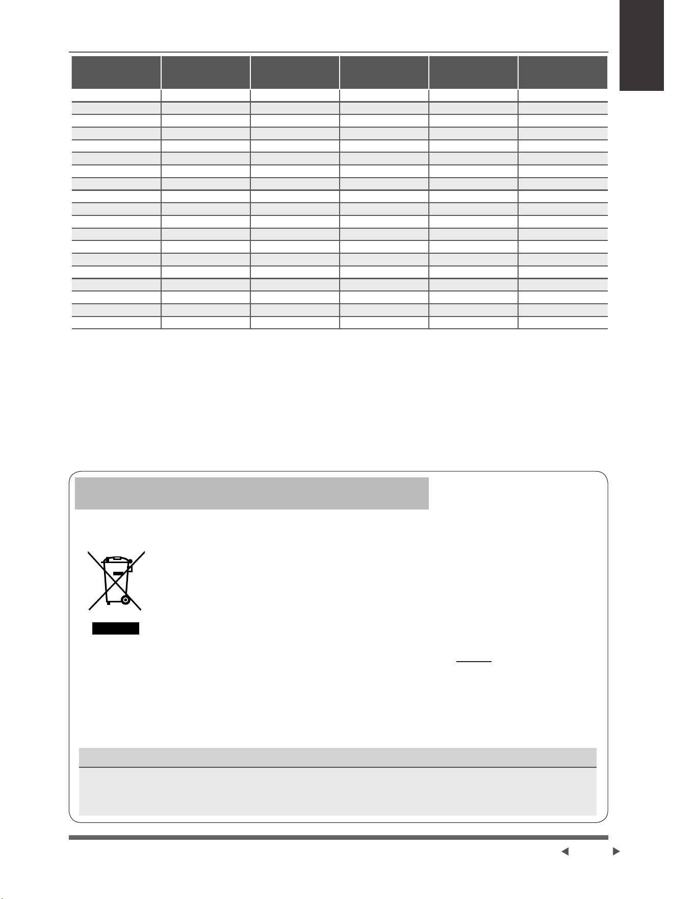
Consignes de
Sécurité
Quantité de
réfrigérant à
charger Ng
Hauteur
d’installation
m
Surface minimale
de la pièce mð
Quantité de
réfrigérant à
charger Ng
Hauteur
d’installation
m
Surface minimale
de la pièce mð
9 /1 /1
36 /4 /3
54 /6 /4
25 /3 /2
63 /7 /5
Ɣ /HVFRQQHFWHXUVPpFDQLTXHVUpXWLOLVDEOHVHWOHVMRLQWVG¶pYDVHPHQWQHVRQWSDVDXWRULVpVjO¶LQWpULHXU
([LJHQFHGHODQRUPH(1
Ɣ /HVFRQQHFWHXUVPpFDQLTXHVXWLOLVpVjO¶LQWpULHXUQHGRLYHQWSDVGpSDVVHUJDQjGHODSUHVVLRQ
PD[LPDOHDGPLVVLEOH/RUVTXHOHVFRQQHFWHXUVPpFDQLTXHVVRQWUpXWLOLVpVjO¶LQWpULHXUOHVSLqFHVG¶pWDQFKpLWp
GRLYHQWrWUHUHPSODFpHV/RUVTXHOHVMRLQWVSODWVVRQWUpXWLOLVpVjO¶LQWpULHXUODSDUWLHG¶pYDVHPHQWGRLWrWUH
UHIDEULTXpH([LJHQFHGHODQRUPH8/
Ɣ /RUVTXHOHVFRQQHFWHXUVPpFDQLTXHVVRQWUpXWLOLVpVjO¶LQWpULHXUOHVSLqFHVG¶pWDQFKpLWpGRLYHQWrWUH
UHPSODFpHV/RUVTXHOHVMRLQWVSODWVVRQWUpXWLOLVpVjO¶LQWpULHXUODSDUWLHG¶pYDVHPHQWGRLWrWUHUHIDEULTXpH
([LJHQFHGHODQRUPH,(&
Ɣ /HVFRQQHFWHXUVPpFDQLTXHVXWLOLVpVjOLQWpULHXUGRLYHQWrWUHFRQIRUPHVjODQRUPH,62
Page 7
&HPDUTXDJH¿JXUDQWVXUOHSURGXLWRXGDQVVDGRFXPHQWDWLRQLQGLTXHTXHOHVGpFKHWVG¶pTXLSHPHQWV
pOHFWULTXHVHWpOHFWULTXHVQHGRLYHQWSDVrWUHPpODQJpVDYHFOHVGpFKHWVPpQDJHUVRUGLQDLUHV
Disposition Correcte du Produit
Déchets d’équipements électriques et électroniques
Le présent appareil contient du réfrigérant et d’autres matériaux potentiellement dangereux. Lors de la mise
DXUHEXWGXSUpVHQWDSSDUHLOODORLH[LJHXQHFROOHFWHHWXQWUDLWHPHQWVSpFLDX[Ne pas disposer ce produit
DYHFOHVGpFKHWVPpQDJHUVRXOHVGpFKHWVPXQLFLSDX[QRQWULpV
/RUVGHODPLVHDXUHEXWGXSUpVHQWDSSDUHLOOHVRSWLRQVVXLYDQWHVVRQWGLVSRQLEOHV
• 'LVSRVH]O¶DSSDUHLOGDQVXQHLQVWDOODWLRQPXQLFLSDOHGHFROOHFWHGHVGpFKHWVpOHFWULTXHV
• /RUVGHO¶DFKDWG¶XQQRXYHODSSDUHLOOHUHYHQGHXUUHSUHQGUDO¶DQFLHQXQLWpJUDWXLWHPHQW
• Le fabricant reprendra l’ancien appareil gratuitement.
• 9HQGH]O¶DSSDUHLODX[UHYHQGHXUVFHUWL¿pVGHIHUUDLOOH
Avis spécial
La mise au rebut du présent appareil dans la forêt ou dans d’autres environnements naturels est dangereuse
SRXUODVDQWpHWQXLVLEOHjO¶HQYLURQQHPHQW'HVVXEVWDQFHVGDQJHUHXVHVSHXYHQWV¶LQ¿OWUHUGDQVOHVHDX[
VRXWHUUDLQHVHWHQWUHUGDQVODFKDvQHDOLPHQWDLUH
Directives Européennes de Traitement
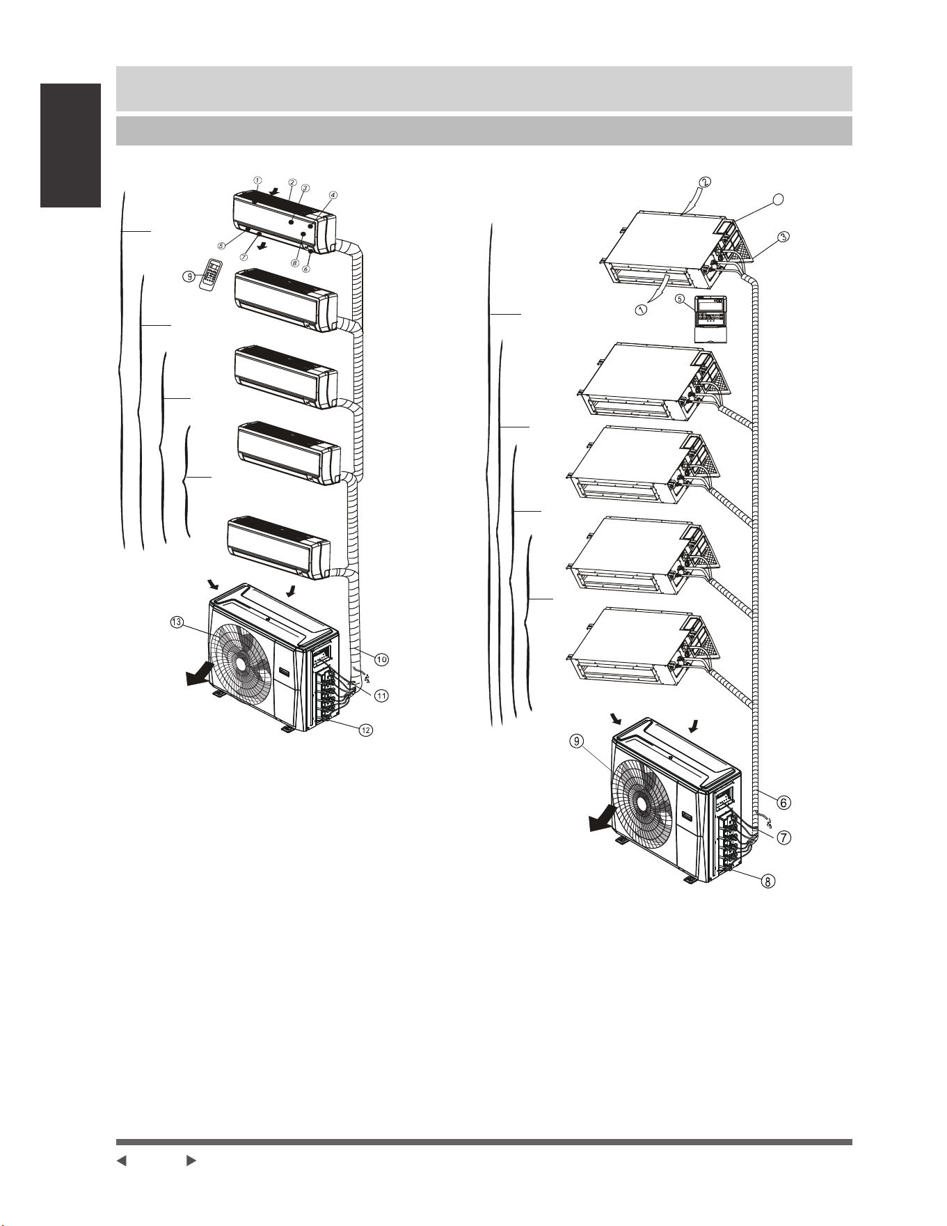
Pièces et fonctions
principales de
l’unité intérieure
Page 8
Pièces et fonctions principales de l’unité intérieure
Pièces de l’unité
$7\SHGHPXUVXVSHQGX
Entrée d’air
Un-cinq
Un-quatre
Un-trois
Un-jumeau
Sortie d’air
Sortie d’air
Unité intérieure
1. Cadre de panneau
*ULOOHG¶DGPLVVLRQG¶DLUDUULqUH
3. Panneau avant
)LOWUHGHSXULILFDWLRQGHO¶DLU)LOWUHjDLUDUULqUH
3HUVLHQQHKRUL]RQWDOH
eFUDQG¶DIILFKDJH/&'
7. Volet vertical
8. Bouton de commande manuelle
9. Support de la télécommande
Unité extérieure
7X\DXGHGUDLQDJHWX\DXGHUDFFRUGHPHQWGX
réfrigérant
11. Câble de connexion
12. Vanne d’arrêt
13. Capot du ventilateur
%7\SHGHFRQGXLWSODIRQG
4
Un-cinq
Un-quatre
Un-trois
Un-jumeau
Unité intérieure
1. Sortie d’air
2. Entrée d’air
3. Filtre d’air
&DELQHWGHFRQWU{OHpOHFWULTXH
5. Télécommande câblée
Unité extérieure
7X\DXGHGUDLQDJHWX\DXGHUDFFRUGHPHQWGX
réfrigérant
7. Câble de connexion
8. Vanne d’arrêt
9. Capot du ventilateur
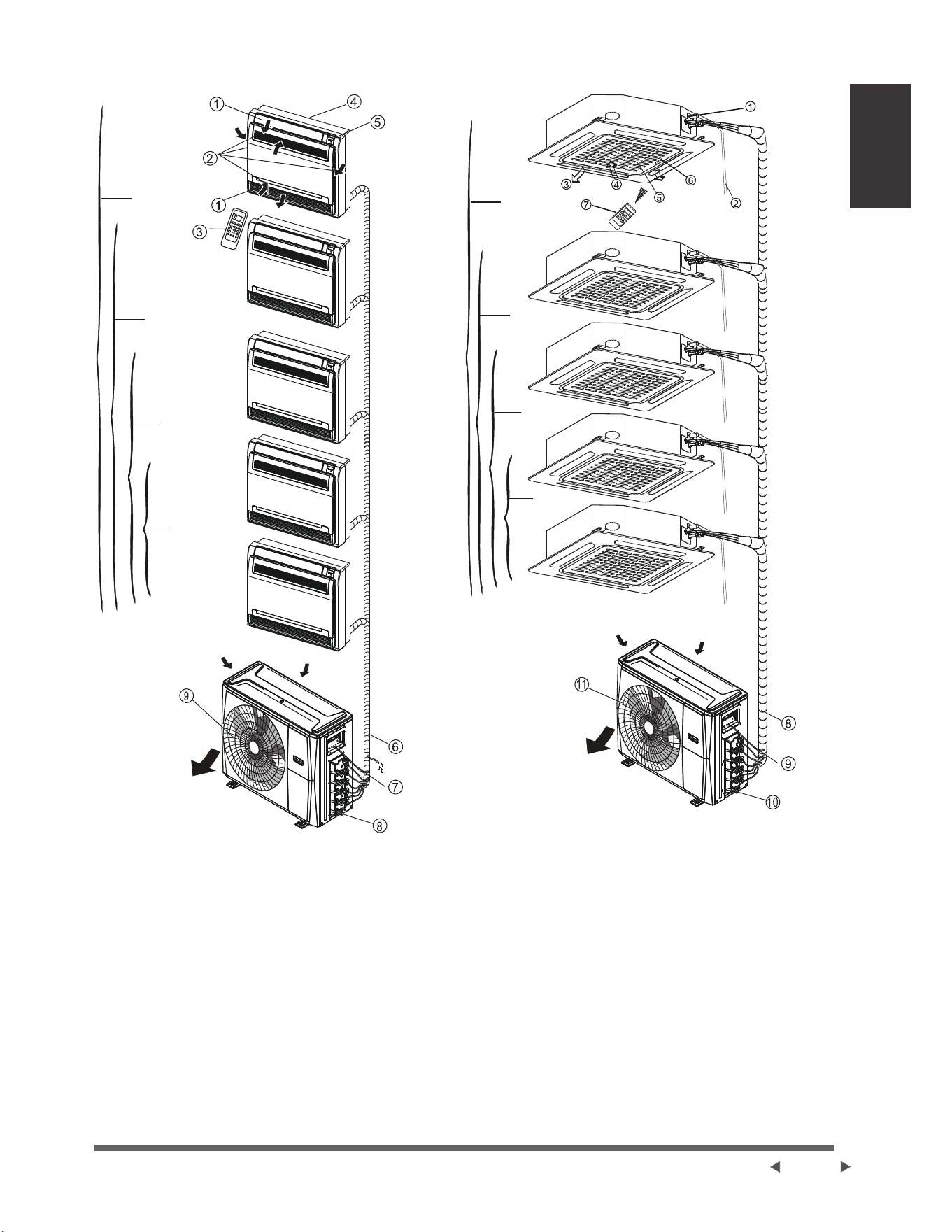
Pièces et fonctions
principales de
l’unité intérieure
Page 9
& 7\SHGHVROHWGHERXWFRQVROH
Un-cinq
Un-quatre
Un-trois
Un-jumeau
Unité intérieure
3HUVLHQQHGXIOX[G¶DLUjODVRUWLHG¶DLU
(QWUpHG¶DLUFRQWHQDQWXQILOWUHjDLU
3. Télécommande
3LqFHG¶LQVWDOODWLRQ
3DQQHDXG¶DIILFKDJH
Unité extérieure
7X\DXGHGUDLQDJHWX\DXGHUDFFRUGHPHQWGX
réfrigérant
7. Câble de connexion
8. Vanne d’arrêt
9. Capot du ventilateur
' 7\SHGHFDVVHWWHFRPSDFWHjTXDWUHYRLHV
Un-cinq
Un-quatre
Un-trois
Un-jumeau
Unité intérieure
1. Pompe de drainage (drainage de l’eau de l’unité
LQWpULHXUH
2. Tuyau de drainage
3. Sortie d’air
4. Entrée d’air
5. Grille d’entrée d’air
3DQQHDXG¶DIILFKDJH
7. Télécommande
Unité extérieure
8. Raccordement du tuyau de réfrigérant
9. Câble de connexion
10. Vanne d’arrêt
11. Capot du ventilateur

Pièces et fonctions
principales de
l’unité intérieure
Page 10
NOTE : 3RXUOHVFOLPDWLVHXUVGHW\SHPXOWLVSOLWXQHXQLWpH[WpULHXUHSHXWrWUHDVVRFLpHjGLIIpUHQWVW\SHV
G¶XQLWpVLQWpULHXUHV7RXWHVOHVLPDJHVGDQVOHPDQXHOVRQWXQLTXHPHQWjGHV¿QVG¶H[SOLFDWLRQ9RWUH
FOLPDWLVHXUSHXWrWUHOpJqUHPHQWGpYLDQWV¶LOHVWGHIRUPHVLPLODLUH/HVSDJHVVXLYDQWHVSUpVHQWHQWSOXVLHXUV
W\SHVG¶XQLWpVLQWpULHXUHVTXLSHXYHQWrWUHDVVRFLpHVDX[XQLWpVH[WpULHXUHV
Des Conditions de Fonctionnement
Température de fonctionnement
/RUVTXHYRWUHFOLPDWLVHXUHVWXWLOLVpHQGHKRUVGHVSODJHVGHWHPSpUDWXUHVXLYDQWHVFHUWDLQHVIRQFWLRQVGH
protection de sécurité peuvent s’activer et entraîner la désactivation de l’unité.
Mode COOL Mode HEAT Mode DRY
POUR LES UNITÉS
EXTÉRIEURES AVEC LE
RECHAUFFEUR ÉLECTRIQUE
AUXILIAIRE
/RUVTXHODWHPSpUDWXUHH[WpULHXUH
HVWLQIpULHXUHj&)QRXV
vous recommandons fortement
GHJDUGHUO¶XQLWpEUDQFKpHj
tout moment pour assurer une
SHUIRUPDQFHUpJXOLqUHHWFRQWLQXH
Température
ambiante
17°C - 32°C
))
0°C - 30°C
))
10°C - 32°C
))
Température
extérieure
0°C - 50°C
))
-15°C - 24°C
))
0°C - 50°C
))
-15°C - 50°C
))
3RXUOHVPRGqOHV
DYHFOHVV\VWqPHV
de refroidissement
à basse
WHPSpUDWXUH
0°C - 50°C
))
0°C - 52°C
))
3RXUOHVPRGqOHV
tropicaux
VSpFLDX[
0°C - 52°C
))
3RXUOHVPRGqOHV
tropicaux
VSpFLDX[
NOTE : +XPLGLWpUHODWLYHGHODSLqFHLQIpULHXUHj6LOHFOLPDWLVHXUIRQFWLRQQHDXGHOjGHFHWWHYDOHXUVD
surface peut attirer la condensation. Réglez le volet d’aération vertical sur son angle maximum (verticalement par
UDSSRUWDXVROHWUpJOH]OHPRGHYHQWLODWLRQe/(9e(
Pour optimiser davantage les performances de votre unité, procédez comme suit :
Ɣ Gardez les portes et les fenêtres fermées.
Ɣ /LPLWH]ODFRQVRPPDWLRQG¶pQHUJLHHQXWLOLVDQWOHVIRQFWLRQV7,0(5210LQXWHULH$FWLYpHHW7,0(52))
0LQXWHULH'pVDFWLYpH
Ɣ 1HSDVEORTXHUOHVHQWUpHVRXOHVVRUWLHVG¶DLU
Ɣ ,QVSHFWH]HWQHWWR\H]UpJXOLqUHPHQWOHV¿OWUHVG¶DLU

Pièces et fonctions
principales de
l’unité intérieure
Page 11
Fonctions
Protection du climatiseur Protection du
compresseur
• Le compresseur ne peut pas redémarrer pendant 3
PLQXWHVDSUqVVRQDUUrW
Air anti-froid modèles de refroidissement et de
chauffage uniquement
• L’unité est conçue pour ne pas souffler d’air froid en
PRGH+($7ORUVTXHO¶pFKDQJHXUGHFKDOHXULQWpULHXU
se trouve dans l’une des trois situations suivantes et
TXHODWHPSpUDWXUHUpJOpHQ¶DSDVpWpDWWHLQWH
$ /RUVTXHOHFKDXIIDJHYLHQWGHFRPPHQFHU
% 3HQGDQWOHGpJLYUDJH
& &KDXIIDJHjEDVVHWHPSpUDWXUH
• Le ventilateur intérieur ou extérieur s’arrête
GHIRQFWLRQQHUORUVGXGpJLYUDJHPRGqOHVGH
UHIURLGLVVHPHQWHWGHFKDXIIDJHXQLTXHPHQW
Dégivrage modèles de refroidissement et de
chauffage uniquement
• Le gel peut être généré sur l’unité extérieure pendant
XQF\FOHGHFKDXIIDJHORUVTXHODWHPSpUDWXUH
H[WpULHXUHHVWEDVVHHWTXHO¶KXPLGLWpHVWpOHYpH
FHTXLHQWUDvQHXQHEDLVVHGHODSXLVVDQFHGH
FKDXIIDJHGDQVOHFOLPDWLVHXU
• 'DQVFHVFRQGLWLRQVOHFOLPDWLVHXUDUUrWHUDOHV
IRQFWLRQQHPHQWVGHFKDXIIDJHHWFRPPHQFHUDj
GpJLYUHUDXWRPDWLTXHPHQW
• Le temps de dégivrage peut varier de 4 à 10 minutes
en fonction de la température extérieure et la
TXDQWLWpGHJLYUHDFFXPXOpVXUO¶XQLWpH[WpULHXUH
Redémarrage automatique certains modèles
(QFDVGHSDQQHG¶DOLPHQWDWLRQOHV\VWqPHV¶DUUrWH
LPPpGLDWHPHQW/RUVTXHO¶DOLPHQWDWLRQUHYLHQW
le voyant de fonctionnement de l’unité intérieure
FOLJQRWHUD3RXUUHGpPDUUHUO¶XQLWpDSSX\H]VXU le
bouton
ON/OFF de la télécommande.6LOHV\VWqPH
GLVSRVHG¶XQHIRQFWLRQGHUHGpPDUUDJHDXWRPDWLTXH
l’unité redémarrera avec les mêmes réglages.
Un brouillard blanc s’échappe de l’unité intérieure
• Un brouillard blanc peut être généré en raison d’une
grande différence de température entre l’entrée et
ODVRUWLHG¶DLUHQPRGH&22/GDQVOHVHQGURLWVR
O¶KXPLGLWpUHODWLYHHVWpOHYpH
• Un brouillard blanc peut être généré en raison de
O¶KXPLGLWpFUppHGDQVOHSURFHVVXVGHGpJLYUDJH
ORUVTXHOHFOLPDWLVHXUUHGpPDUUHHQPRGH+($7
DSUqVOHGpJLYUDJH
Bruit provenant du climatiseur
• 9RXVSRXYH]HQWHQGUHXQIDLEOHVLIÀHPHQWORUVTXH
le compresseur fonctionne ou vient de s’arrêter
GHIRQFWLRQQHU&HEUXLWHVWFHOXLGXUpIULJpUDQWTXL
s’écoule ou s’arrête.
• Vous pouvez également entendre un faible
©JULQFHPHQWªORUVTXHOHFRPSUHVVHXUIRQFWLRQQH
ou vient de s’arrêter de fonctionner. Cela est dû à
ODGLODWDWLRQWKHUPLTXHHWjODFRQWUDFWLRQIURLGHGHV
SLqFHVHQSODVWLTXHGHO¶XQLWpORUVTXHODWHPSpUDWXUH
FKDQJH
• 2QSHXWHQWHQGUHXQEUXLWGDXIDLWTXHOHYROHWVH
UHPHWGDQVVDSRVLWLRQLQLWLDOHORUVTXHO¶DOLPHQWDWLRQ
est activée.
Poussière s’échappant de l’unité intérieure.
&HODH[LVWHORUVTXHOHFOLPDWLVHXUQ¶DSDVpWpXWLOLVp
SHQGDQWXQHORQJXHSpULRGHRXORUVGHVDSUHPLqUH
utilisation.
Odeur émise par l’unité intérieure.
&HODHVWGDXIDLWTXHO¶XQLWpLQWpULHXUHGpJDJHGHV
RGHXUVGHPDWpULDX[GHFRQVWUXFWLRQGHPHXEOHVRX
de fumée.
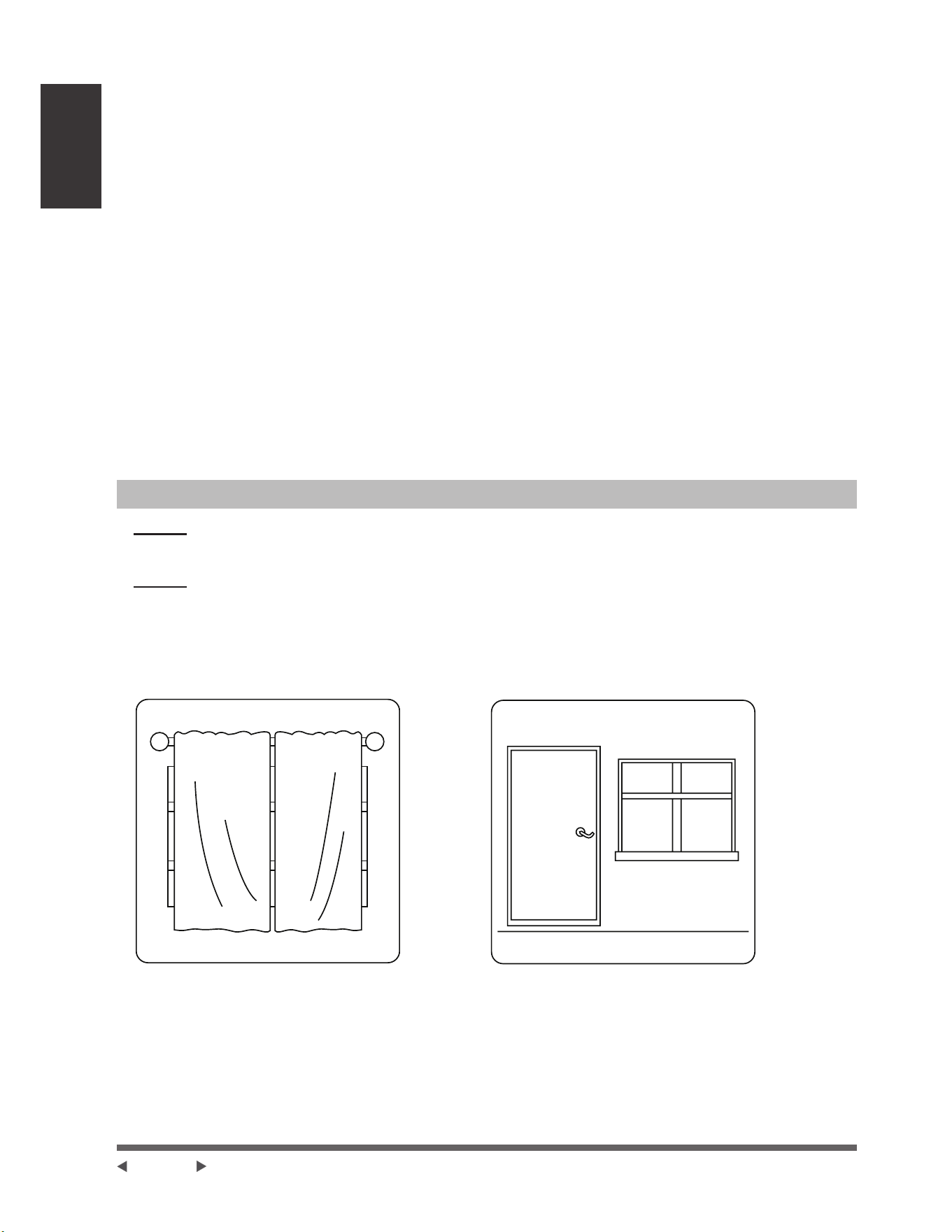
Pièces et fonctions
principales de
l’unité intérieure
Page 12
Le climatiseur passe en mode FAN ONLY
VENTILATION UNIQUEMENT à partir du mode
COOL FROID ou HEAT CHAUFFAGE pour
les modèles de refroidissement et de chauffage
uniquement.
/RUVTXHODWHPSpUDWXUHLQWpULHXUHDWWHLQWODWHPSpUDWXUH
GHFRQVLJQHOHFRPSUHVVHXUV¶DUUrWHDXWRPDWLTXHPHQW
et le climatiseur passe en mode FAN ONLY. Le
FRPSUHVVHXUGpPDUUHUDORUVTXHODWHPSpUDWXUH
intérieure augmente en mode COOL ou diminue en
PRGH+($7MXVTX¶DXSRLQWGHFRQVLJQH
Des gouttelettes d’eau peuvent se former à la surface
GHO¶XQLWpLQWpULHXUHORUVTXHOHUHIURLGLVVHPHQWVHSURGXLW
GDQVGHVFRQGLWLRQVG¶KXPLGLWpUHODWLYHPHQWpOHYpH
SOXVGH$GMXVWH]ODSHUVLHQQHKRUL]RQWDOHjOD
position de sortie d’air maximale et sélectionnez une
vitesse de ventilateur HIGH.
Mode chauffage uniquement pour les modèles de
refroidissement et de chauffage
/HFOLPDWLVHXUDVSLUHODFKDOHXUGHO¶XQLWpH[WpULHXUH
HWODOLEqUHYLDO¶XQLWpLQWpULHXUHSHQGDQWOHFKDXIIDJH
/RUVTXHODWHPSpUDWXUHH[WpULHXUHEDLVVHODFKDOHXU
DEVRUEpHSDUOHFOLPDWLVHXUGLPLQXHHQFRQVpTXHQFH
(QPrPHWHPSVODFKDUJHWKHUPLTXHGXFOLPDWLVHXU
augmente en raison d’une plus grande différence
entre la température intérieure et extérieure. Si une
température confortable ne peut pas être réalisée avec
OHVHXOFOLPDWLVHXULOHVWUHFRPPDQGpG¶XWLOLVHUXQ
GLVSRVLWLIGHFKDXIIDJHVXSSOpPHQWDLUH
/DIRXGUHRXXQWpOpSKRQHVDQV¿OGHYRLWXUH
IRQFWLRQQDQWjSUR[LPLWpSHXYHQWSURYRTXHUXQ
G\VIRQFWLRQQHPHQWGHO¶XQLWp'pEUDQFKH]O¶XQLWp
GHVDVRXUFHG¶DOLPHQWDWLRQSXLVUHEUDQFKH]O¶XQLWp
à la source d’alimentation. Appuyez sur le bouton
ON/OFF de la télécommande pour redémarrer les
fonctionnements.
Conseils d’Économie d’Énergie
• NE PAS régler l’unité à des températures excessives.
• 3HQGDQWOHUHIURLGLVVHPHQWIHUPH]OHVULGHDX[SRXUpYLWHUOHVUD\RQVGLUHFWVGXVROHLO
• /HVSRUWHVHWOHVIHQrWUHVGRLYHQWUHVWHUIHUPpHVSRXUJDUGHUO¶DLUIUDLVRXFKDXGGDQVODSLqFH
• NE PASSODFHUG¶REMHWVSUqVGHO¶HQWUpHHWGHODVRUWLHG¶DLUGHO¶XQLWp&HODUpGXLUDO¶HI¿FDFLWpGHO¶XQLWp
• 5pJOH]XQHPLQXWHULHHWXWLOLVH]OHPRGHLQWpJUp6/((3(&2120<OHFDVpFKpDQW
• 6LYRXVSUpYR\H]GHQHSDVXWLOLVHUO¶XQLWpSHQGDQWXQHORQJXHSpULRGHUHWLUH]OHVSLOHVGHODWpOpFRPPDQGH
• 1HWWR\H]OH¿OWUHjDLUWRXWHVOHVGHX[VHPDLQHV8Q¿OWUHVDOHSHXWUpGXLUHO¶HI¿FDFLWpGXUHIURLGLVVHPHQWRXGX
FKDXIIDJH
• $MXVWH]FRUUHFWHPHQWOHVSHUVLHQQHVHWpYLWH]OHÀX[G¶DLUGLUHFW
La fermeture des rideaux pendant le
chauffage aide également à garder la
chaleur à l’intérieur
Les portes et les fenêtres doivent
rester fermées

Opération
Manuelles et
Entretien
Page 13
Opérations Manuelles et Maintenance
Sélection de mode de fonctionnement
/RUVTXHGHX[RXSOXVLHXUVXQLWpVLQWpULHXUHV
IRQFWLRQQHQWVLPXOWDQpPHQWDVVXUH]YRXVTXHOHV
PRGHVQHVRQWSDVHQFRQÀLWOHVXQVDYHFOHVDXWUHV
Le mode HEAT a la priorité sur tous les autres modes.
Si l’unité a initialement commencé à fonctionner en
PRGH+($7OHVDXWUHVXQLWpVQHSHXYHQWIRQFWLRQQHU
TX¶HQPRGH+($73DUH[HPSOH6LO¶XQLWpGpPDUUpH
LQLWLDOHPHQWIRQFWLRQQHHQPRGH&22/RX)$1
les autres unités peuvent fonctionner sous n’importe
TXHOPRGHVDXIOHPRGH+($76LO¶XQHGHVXQLWpV
IRQFWLRQQHHQPRGH+($7OHVDXWUHVXQLWpVHQ
IRQFWLRQQHPHQWFHVVHURQWGHIRQFWLRQQHUHWDI¿FKHURQW
©ªXQLTXHPHQWSRXUOHVXQLWpVDYHFIHQrWUH
G¶DI¿FKDJHRXOHYR\DQWG¶LQGLFDWLRQDXWRPDWLTXHHW
GHIRQFWLRQQHPHQWFOLJQRWHUDUDSLGHPHQWOHYR\DQW
d’indication de dégivrage s’éteindra et le voyant
d’indication de la minuterie restera allumé (pour les
XQLWpVVDQVIHQrWUHG¶DI¿FKDJH$OWHUQDWLYHPHQWOH
YR\DQWGHGpJLYUDJHHWG¶DODUPHOHFDVpFKpDQW
V¶DOOXPHUDRXOHYR\DQWGHIRQFWLRQQHPHQWFOLJQRWHUD
UDSLGHPHQWHWOHYR\DQWGHODPLQXWHULHV¶pWHLQGUDSRXU
OHW\SHDXVROHWGHERXW
Maintenance
Si vous prévoyez de laisser l’unité inactive pendant une
ORQJXHSpULRGHHIIHFWXH]OHVWkFKHVVXLYDQWHV
1HWWR\H]O¶XQLWpLQWpULHXUHHWOH¿OWUHG¶DLU
2. Sélectionnez le mode FAN ONLY et laissez le
ventilateur intérieur fonctionner pendant un certain
WHPSVSRXUVpFKHUO¶LQWpULHXUGHO¶XQLWp
'pEUDQFKH]O¶DOLPHQWDWLRQpOHFWULTXHHWUHWLUH]OD
batterie de la télécommande.
9pUL¿H]SpULRGLTXHPHQWOHVFRPSRVDQWVGHO¶XQLWp
extérieure. Contactez un revendeur local ou un
FHQWUHGHVHUYLFHjODFOLHQWqOHVLO¶XQLWpDEHVRLQ
d’être réparé.
NOTE : $YDQWGHQHWWR\HUOHFOLPDWLVHXUDVVXUH]
vous de mettre l’unité en fonctionnement et de
GpEUDQFKHUOHERXFKRQG¶DOLPHQWDWLRQpOHFWULTXH
Fonctionnement optimal
3RXUREWHQLUGHVSHUIRUPDQFHVRSWLPDOHVYHXLOOH]
QRWHUFHTXLVXLW
• $MXVWH]ODGLUHFWLRQGXÀX[G¶DLUD¿QTX¶LOQHVRXIÀH
pas directement sur les personnes.
• $MXVWH]ODWHPSpUDWXUHSRXUREWHQLUOHSOXVKDXW
niveau de confort possible. Ne pas régler l’unité sur
des niveaux de température excessifs.
• Fermez les portes et les fenêtres en mode COOL ou
HEAT.
• Utilisez le bouton TIMER ON de la télécommande
SRXUVpOHFWLRQQHUO¶KHXUHjODTXHOOHYRXVVRXKDLWH]
démarrer votre climatiseur.
• 1HSODFH]DXFXQREMHWSUqVGHO¶HQWUpHRXGHOD
VRUWLHG¶DLUFDUODSXLVVDQFHGXFOLPDWLVHXUSHXWrWUH
réduite et le climatiseur peut cesser de fonctionner.
• 1HWWR\H]UpJXOLqUHPHQWOH¿OWUHjDLUVLQRQOD
SHUIRUPDQFHGHUHIURLGLVVHPHQWRXGHFKDXIIDJH
ULVTXHG¶rWUHUpGXLWH
• 1HSDVRSpUHUO¶XQLWpDYHFXQHSHUVLHQQHKRUL]RQWDOH
en position fermée.
Recommandations:
Pour les unités ayant la fonction de chauffage
électrique, lorsque la température ambiante
extérieure est inférieure à 0C 32F, il est
fortement recommandé de garder l’unité branchée
a¿n de garantir un bon fonctionnement.
Lorsque le climatiseur doit être réutilisé:
• 8WLOLVH]XQFKLIIRQVHFSRXUHVVX\HUODSRXVVLqUH
DFFXPXOpHVXUODJULOOHG¶HQWUpHG¶DLUDUULqUHD¿Q
G¶pYLWHUTXHODSRXVVLqUHQHVRLWGLVSHUVpHjSDUWLUGH
l’unité intérieure.
• 9pUL¿H]TXHOHFkEODJHQ¶HVWSDVFRXSpRX
déconnecté.
• 9pUL¿H]TXHOH¿OWUHjDLUHVWLQVWDOOp
• 9pUL¿H]VLODVRUWLHRXO¶HQWUpHG¶DLUHVWEORTXpHDSUqV
TXHOHFOLPDWLVHXUQ¶DSDVpWpXWLOLVpSHQGDQWXQH
longue période.
Dépannage
Dépannage
CONSIGNES DE SÉCURITÉ
6LO¶XQHGHVFRQGLWLRQVVXLYDQWHVVHSURGXLWpWHLJQH]YRWUHXQLWpLPPpGLDWHPHQW
• /HFkEOHG¶DOLPHQWDWLRQHVWHQGRPPDJpRXDQRUPDOHPHQWFKDXG
• Vous sentez une odeur de brûlé
• L’unité émet de sons forts ou anormaux
• 8QIXVLEOHG¶DOLPHQWDWLRQVHGpFOHQFKHRXOHGLVMRQFWHXUVHGpFOHQFKHIUpTXHPPHQW
• 'HO¶HDXRXG¶DXWUHVREMHWVWRPEHQWGDQVRXKRUVGHO¶XQLWp
NE PAS ESSAYER DE LE RÉPARER PAR VOUS-MÊME ! CONTACTEZ UN
FOURNISSEUR DE SERVICES AUTORISÉ IMMÉDIATEMENT !
Problèmes courants
/HVSUREOqPHVVXLYDQWVQHFRQVWLWXHQWSDVXQG\VIRQFWLRQQHPHQWHWGDQVODSOXSDUWGHVFDVQHQpFHVVLWHQW
aucune réparation.
Problème Causes Possibles
L’unité ne s’allume
SDVORUVTXHYRXV
appuyez sur le
bouton ON/ OFF
/¶XQLWpDXQHIRQFWLRQGHSURWHFWLRQGHPLQXWHVODTXHOOHHPSrFKHO¶XQLWpGHVXUFKDUJHU
L’unité ne peut pas être redémarrée dans les trois minutes suivant la mise en arrêt.
0RGqOHVGHUHIURLGLVVHPHQWHWGHFKDXIIDJH6LOHYR\DQWGHIRQFWLRQQHPHQWHWGH35(
'()3UpFKDXIIDJH'pJLYUDJHVRQWDOOXPpVODWHPSpUDWXUHH[WpULHXUHHVWWURSIURLGHHW
le vent anti-froid de l’unité est activé pour dégivrer l’unité.
3RXUOHVPRGqOHVjUHIURLGLVVHPHQWXQLTXHPHQW6LO¶LQGLFDWHXUGH©YHQWLODWHXUXQLTXHª
V¶DOOXPHODWHPSpUDWXUHH[WpULHXUHHVWWURSEDVVHHWODSURWHFWLRQDQWLJHOGHO¶XQLWpHVW
activée pour dégivrer l’unité.
L’unité passe du
mode COOL au
mode FAN
/¶XQLWpSHXWFKDQJHUVRQUpJODJHSRXUHPSrFKHUODIRUPDWLRQGHJHOVXUO¶XQLWp8QHIRLV
TXHODWHPSpUDWXUHDXJPHQWHO¶XQLWpUHFRPPHQFHUDjIRQFWLRQQHU
/DWHPSpUDWXUHUpJOpHDpWpDWWHLQWHjSDUWLUGHODTXHOOHO¶XQLWppWHLQWOHFRPSUHVVHXU
/¶XQLWpFRQWLQXHUDjIRQFWLRQQHUORUVTXHODWHPSpUDWXUHÀXFWXHUDjQRXYHDX
L’unité intérieure
émet une brume
EODQFKH
'DQVOHVUpJLRQVKXPLGHVXQHJUDQGHGLIIpUHQFHGHWHPSpUDWXUHHQWUHO¶DLUGDQVODSLqFH
HWO¶DLUFRQGHQVpSHXWSURYRTXHUXQHEUXPHEODQFKH
Les unités
intérieures et
extérieures
émettent une brume
EODQFKH
/RUVTXHO¶XQLWpUHGpPDUUHHQPRGH+($7&+$8'DSUqVOHGpJLYUDJHXQHEUXPH
EODQFKHSHXWrWUHpPLVHHQUDLVRQGHO¶KXPLGLWpJpQpUpHSDUOHSURFHVVXVGHGpJLYUDJH
L’unité intérieure fait
du bruit
8QJULQFHPHQWVHIDLWHQWHQGUHORUVTXHOHV\VWqPHHVWe7(,17RXHQPRGH)52,'/H
EUXLWHVWpJDOHPHQWDXGLEOHORUVTXHODSRPSHGHGUDLQDJHHQRSWLRQHVWHQVHUYLFH
8QEUXLWGHJULQFHPHQWSHXWVHSURGXLUHDSUqVDYRLUIDLWIRQFWLRQQHUO¶XQLWpHQPRGH
+($7&+$8'HQUDLVRQGHO¶H[SDQVLRQHWGHODFRQWUDFWLRQGHVSLqFHVHQSODVWLTXHGH
l’unité.
Page 14
Dépannage
Problème Causes Possibles
L’unité intérieure
et l’unité extérieure
font du bruit
8QIDLEOHVLIÀHPHQWSHXWVHSURGXLUHSHQGDQWOHIRQFWLRQQHPHQW&HFLHVWQRUPDOHWHVW
causé par le gaz réfrigérant circulant dans les unités intérieures et extérieures.
8QIDLEOHVLIÀHPHQWSHXWrWUHHQWHQGXORUVTXHOHV\VWqPHGpPDUUHV¶HVWWRXWVLPSOHPHQW
DUUrWpGHIRQFWLRQQHURXHVWHQFRXUVGHGpJLYUDJH&HEUXLWHVWQRUPDOHWSURYRTXpSDU
O¶DUUrWGXJD]UpIULJpUDQWRXOHFKDQJHPHQWGHGLUHFWLRQ
L’unité extérieure
fait du bruit
L’unité fera des sons différents en fonction de son mode de fonctionnement actuel.
/DSRXVVLqUHHVW
émise par l’unité
intérieure ou
extérieure
/¶XQLWpSHXWDFFXPXOHUGHODSRXVVLqUHSHQGDQWGHORQJXHVSpULRGHVGHQRQXWLOLVDWLRQ
HWFHOOHFLVHUDpPLVHORUVTXHO¶XQLWpHVWDOOXPp&HODSHXWrWUHDWWpQXpHQFRXYUDQWO¶XQLWp
pendant de longues périodes d’inactivité.
L’unité émet une
mauvaise odeur
/¶XQLWpSHXWDEVRUEHUOHVRGHXUVGHO¶HQYLURQQHPHQWOHVPHXEOHVODFXLVLQHOHV
FLJDUHWWHVHWFOHVTXHOOHVVHURQWpPLVHVSHQGDQWOHIRQFWLRQQHPHQW
/HV¿OWUHVGHO¶XQLWpVRQWPRLVLVHWGRLYHQWrWUHQHWWR\pV
Le ventilateur de
l’unité extérieure ne
fonctionne pas
3HQGDQWOHIRQFWLRQQHPHQWODYLWHVVHGXYHQWLODWHXUHVWFRQWU{OpHSRXURSWLPLVHUOH
fonctionnement du produit.
Page 15
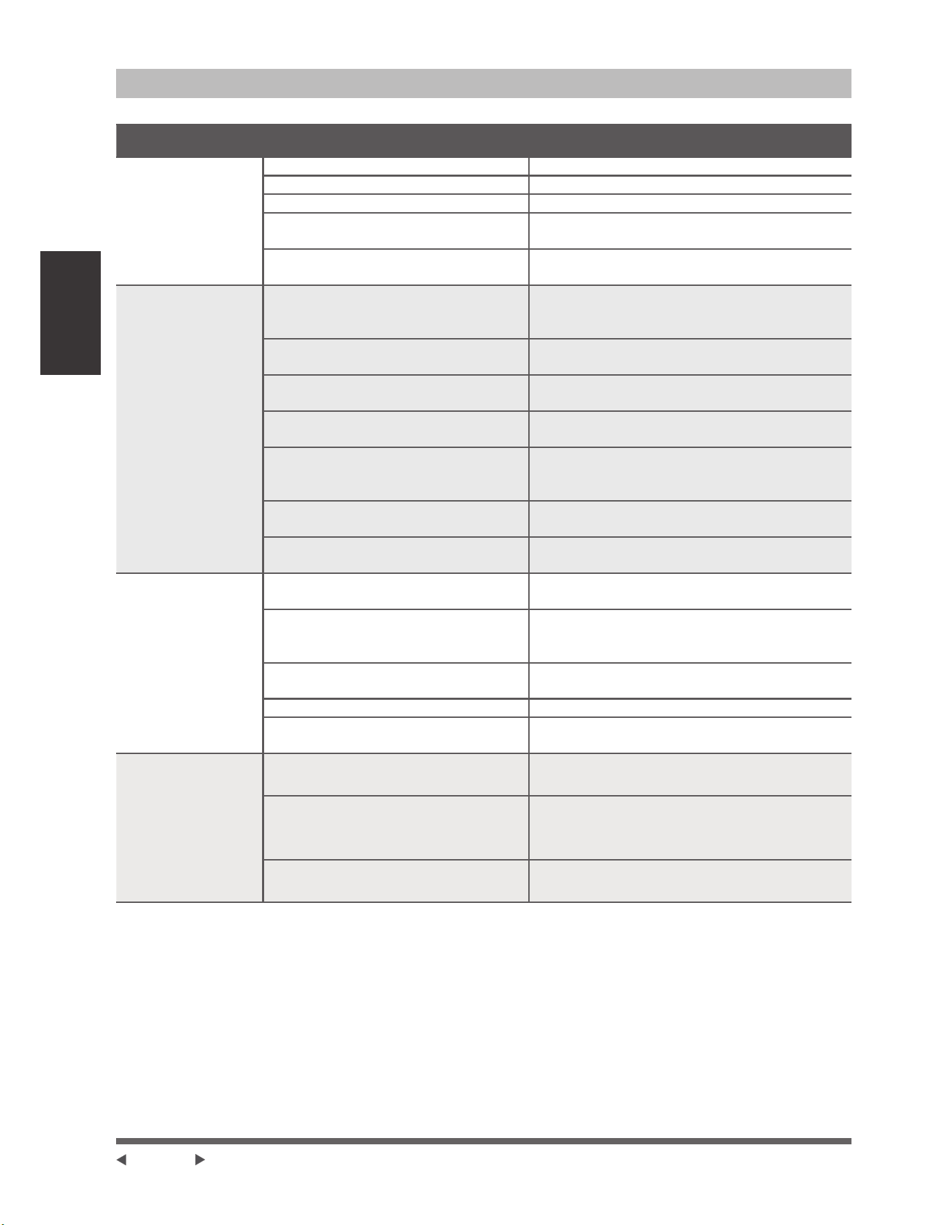
Dépannage
Conseils de dépannage
(QFDVGHSUREOqPHYpUL¿H]OHVSRLQWVVXLYDQWVDYDQWGHFRQWDFWHUXQHHQWUHSULVHGHUpSDUDWLRQ
Problème Causes Possibles Solution
L’unité ne
fonctionne pas
Panne de courant $WWHQGH]TXHO¶DOLPHQWDWLRQVRLWUpWDEOLH
L’interrupteur est éteint Allumez l’unité
Le fusible est sauté Remplacez le fusible
Les batteries de la télécommande
s’épuisent
Remplacez les piles de la télécommande
La protection de 3 minutes de l’unité a
été activée
$WWHQGH]WURLVPLQXWHVDSUqVOHUHGpPDUUDJHGH
l’unité
Mauvaise
performance de
refroidissement
/DFRQ¿JXUDWLRQGHODWHPSpUDWXUH
peut être supérieur à la température
ambiante
Abaissez le réglage de la température
/¶pFKDQJHXUGHFKDOHXUGHO¶XQLWp
intérieure ou extérieure est sale
1HWWR\H]O¶pFKDQJHXUGHFKDOHXUFRQFHUQp
/H¿OWUHjDLUHVWVDOH
5HWLUH]OH¿OWUHHWOHQHWWR\H]FRQIRUPpPHQW
aux instructions
L’entrée ou la sortie d’air de l’une ou
O¶DXWUHXQLWpHVWEORTXp
eWHLJQH]O¶XQLWpHQOHYH]O¶REVWUXFWLRQHWOD
rallumez
Les portes et les fenêtres sont
ouvertes
$VVXUH]YRXVTXHWRXWHVOHVSRUWHVHWIHQrWUHV
soient fermées pendant le fonctionnement de
l’unité
/DFKDOHXUH[FHVVLYHHVWJpQpUpHSDU
ODOXPLqUHGXVROHLO
Fermez les fenêtres et les rideaux pendant les
SpULRGHVGHIRUWHFKDOHXURXGHVROHLO
Faible réfrigérant dû à une fuite ou à
une utilisation à long terme
9pUL¿H]V¶LO\DGHVIXLWHVUHIHUPH]VL
nécessaire et ajoutez du réfrigérant
L’unité se
démarre
et s’arrête
IUpTXHPPHQW
Il y a trop ou peu de réfrigérant dans le
V\VWqPH
9pUL¿H]OHVIXLWHVHWUHFKDUJH]OHV\VWqPHDYHF
du réfrigérant.
,O\DGHO¶DLUGHVJD]LQFRPSUHVVLEOHV
ou des corps étrangers dans le
V\VWqPHGHUpIULJpUDWLRQ
eYDFXH]HWUHFKDUJH]OHV\VWqPHDYHFGX
réfrigérant.
/HFLUFXLWGXV\VWqPHHVWEORTXp
'pWHUPLQH]TXHOFLUFXLWHVWEORTXpHWUHPSODFH]
O¶pTXLSHPHQWGpIHFWXHX[
Le compresseur est cassé Remplacez le compresseur
La tension est trop élevée ou trop
basse
Installez un manostat pour réguler la tension
Mauvaise
performance de
FKDXIIDJH
La température extérieure est
LQIpULHXUHj&)
9pUL¿H]OHVIXLWHVHWUHFKDUJH]OH
V\VWqPHDYHFGXUpIULJpUDQW
L’air froid entre par les portes et
les fenêtres
$VVXUH]YRXVTXHWRXWHVOHVSRUWHV
et fenêtres soient fermées lors de
l’utilisation
Faible réfrigérant dû à une fuite
ou à une utilisation à long terme
9pUL¿H]V¶LO\DGHVIXLWHVUHIHUPH]VL
nécessaire et ajoutez du réfrigérant
Page 16
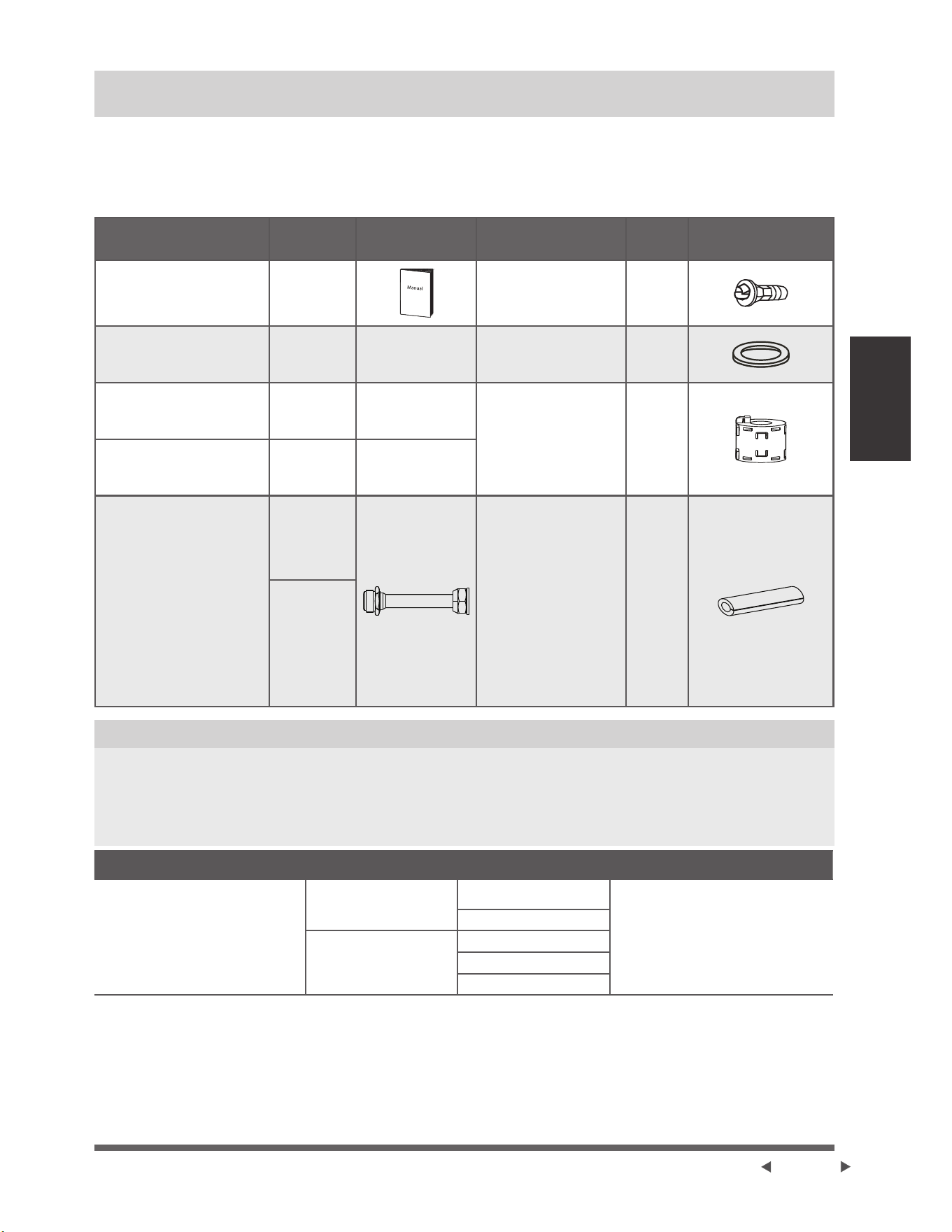
Accessoires
Accessoires
/HV\VWqPHGHFOLPDWLVDWLRQHVWOLYUpDYHFOHVDFFHVVRLUHVVXLYDQWV8WLOLVH]WRXWHVOHVSLqFHVHWDFFHVVRLUHV
G¶LQVWDOODWLRQSRXULQVWDOOHUOHFOLPDWLVHXU8QHLQVWDOODWLRQLQFRUUHFWHSHXWHQWUDvQHUGHVIXLWHVG¶HDXG¶XQFKRF
pOHFWULTXHHWG¶XQLQFHQGLHRXHQWUDvQHUODGpIDLOODQFHGHO¶pTXLSHPHQW/HVDUWLFOHVTXLQHVRQWSDVLQFOXVDYHFOH
FOLPDWLVHXUGRLYHQWrWUHDFKHWpVVpSDUpPHQW
Désignation des accessoires Qté U Forme
Désignation des
accessoires
Qté U Forme
Manuel 2-4
Joint de drainage
certains modèles
1
Plaque d’installation
certains modèles
1
Anneau d’étanchéité
certains modèles
1
Gaine d’expansion en
plastique
5-8
(selon les
PRGqOHV
Anneau magnétique
l’attachez sur le câble
de connexion entre
l’unité intérieure et
l’unité extérieure après
l’installation.
certains modèles
Ils varient
selon le
PRGqOH
Vis auto-taraudage A
5-8
(selon les
PRGqOHV
Connecteur de transfert
emballé avec l’unité
intérieure ou extérieure, selon
les modèles
NOTE : La taille des tuyaux
peut varier d’un unité à
l’autre. Pour répondre aux
différentes exigences de
taille des tuyaux, il est
parfois nécessaire d’installer
un raccord de transfert sur
l’unité extérieure.
3LqFHV
optionnelles
XQHSLqFH
une unité
LQWpULHXUH
Anneau de caoutchouc
de protection du cordon
Si le serre-cordon ne
peut pas s’attacher à
un petit cordon, utilisez
l’anneau en caoutchouc
de protection du
cordon [fourni avec
les accessoires] pour
l’enrouler autour du
cordon. Puis le ¿xez
en place avec le serre-
cordon.
certains modèles
1
3LqFHV
optionnelles
SLqFHV
pour l’unité
H[WpULHXUH
selon les
PRGqOHV
Accessoires optionnels
• ,O\DGHX[W\SHVGHWpOpFRPPDQGHVDYHF¿OHWVDQV¿O
Sélectionnez un contrôleur à distance sur la base des préférences et exigences de consommateur et installez
dans une place appropriée.
)DLWHVUpIpUHQFHDX[FDWDORJXHVHWjODGRFXPHQWDWLRQWHFKQLTXHSRXUOHVLQVWUXFWLRQVVXUODVpOHFWLRQGX
contrôleur à distance convenable.
Désignation Forme Quantité PC
Assemblage de tuyau de
raccordement
Côté liquide
ĭ6,351/4 SR
3LqFHVTXHYRXVGHYH]DFKHWHU
séparément. Consultez le
distributeur concernant la dimension
DSSURSULpHGXWX\DXGHO¶XQLWpTXH
YRXVDFKHWH]
¡9,52 3/8 po
Côté gaz
¡9,52 3/8 po
¡12,7 1/2 po
¡16 5/8 po
Page 17
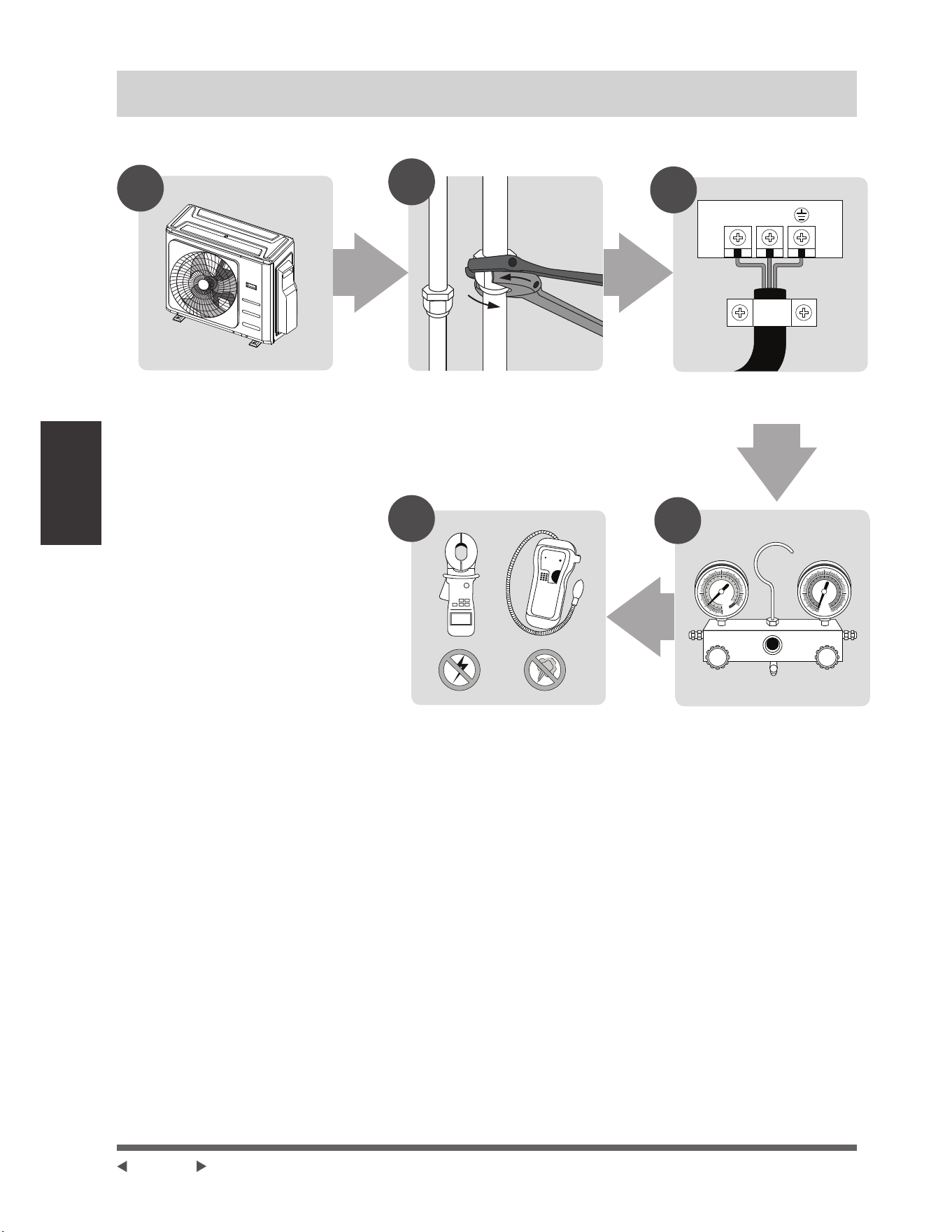
Résumé de
l’installation
Résumé de l’installation
ORDRE D’INSTALLATION
LN
1
2
3
MC MC
4
5
(L1) (L2)
Installez l’unité extérieure Connectez les tuyaux de
réfrigérant
Effectuez une mise en
service
Connectez les câbles
Évacuez le système de
réfrigération
Page 18
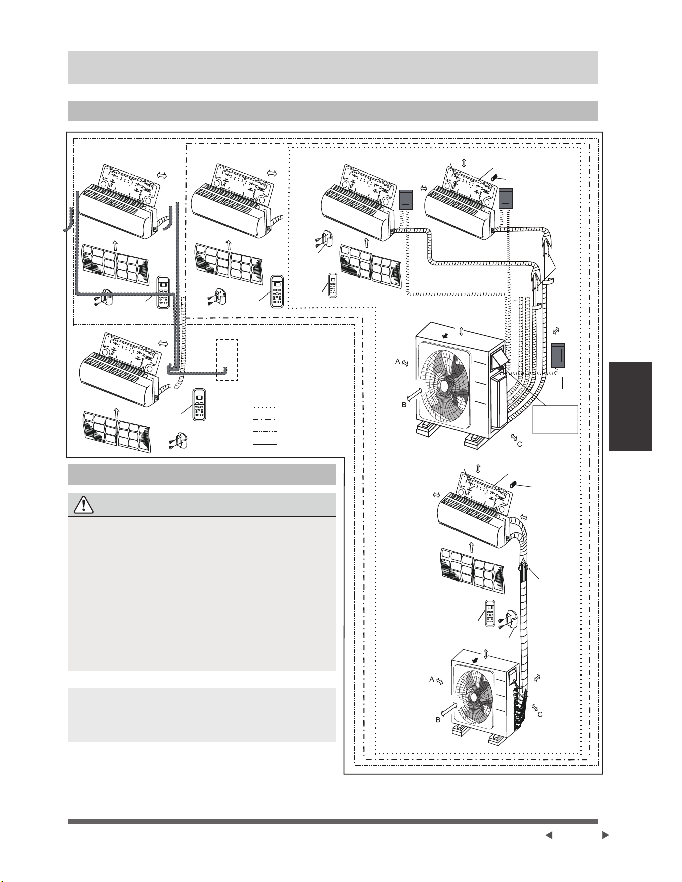
Schéma
d’installation
Schéma d’installation
Schéma d’installation
(2)
1
2
3
5
4
1
(1)
5 4 3
2
Plus de 12cm
Plus de 12cm
Plus de 30cm
Plus de 30cm
Plus de 200cm
Plus de 60cm
Sortie d’air
Sortie d’air
Vis de montage
ST3.9 × 25-C-H
Le nombre maximum
de câbles de connexion
est de 5. Cette section
HVWXQLTXHPHQWjWLWUH
de référence.
Plus de 60cm
Plus de 15cm
3ODTXHG¶LQVWDOODWLRQ
$QFUDJHG¶DWWDFKH
Tuyau de réfrigérant
Plus de 12cm
Plus de 12cm
Plus de 30cm
Plus de 60cm
Plus de 30cm
Plus de 60cm
Plus de 200cm
Filtre à air
Filtre à air
Filtre à air
Télécommande Télécommande
Un-deux
Un-Trois
Un-Quatre
8Q&LQT
Télécommande
Support de la
télécommande
Disjoncteur
à air
Vis de montage
ST3.9 × 25-C-H
Plus de 15cm
3ODTXHG¶LQVWDOODWLRQ
$QFUDJHG¶DWWDFKH
Disjoncteur à air
Tuyau de
drainage
Filtre à air
Filtre à air
Plus de 12cm
Consignes de Sécurité
ATTENTION
• 3RXUpYLWHUG¶HQGRPPDJHUOHVPXUVXWLOLVH]XQ
FKHUFKHXUGHJRXMRQVSRXUORFDOLVHUOHVJRXMRQV
• 8QWX\DXPLQLPXPGHPHVWUHTXLVSRXUPLQLPLVHU
les vibrations et le bruit excessif.
• 'HX[GHVYRLHVGHFLUFXODWLRQG¶DLU$%HW&GRLYHQW
être libres de toute obstruction à tout moment.
• &HWWHLOOXVWUDWLRQHVWXQLTXHPHQWGHVWLQpHjGHV¿QV
de démonstration.
• La forme réelle de votre climatiseur peut être
OpJqUHPHQWGLIIpUHQWH
• /HVOLJQHVGHFXLYUHGRLYHQWrWUHLVROpHVGHPDQLqUH
indépendante.
NOTE : /¶LQVWDOODWLRQGRLWrWUHXQLTXHPHQWHIIHFWXpH
conformément aux normes locales et nationales.
/¶LQVWDOODWLRQSHXWrWUHOpJqUHPHQWGLIIpUHQWHGDQV
différentes régions.
Câble
d’alimentation de
l’unité extérieure
Télécommande
Support de la
télécommande
Télécommande
Page 19
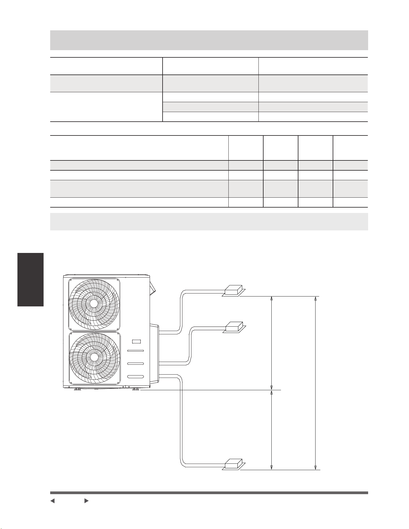
Spéci¿cations
Spéci¿cations
Nombre d’unités pouvant être utilisées
ensemble
Unités connectées 1-5 unités
)UpTXHQFHG¶DUUrWGHGpPDUUDJHGX
compresseur
Temps d’arrêt 3 minutes ou plus
Tension de la source d’alimentation
ÀXFWXDWLRQGHWHQVLRQ jGHODWHQVLRQQRPLQDOH
FKXWHGHWHQVLRQDXGpPDUUDJH jGHODWHQVLRQQRPLQDOH
GpVpTXLOLEUHGHVLQWHUYDOOHV jGHODWHQVLRQQRPLQDOH
Unité: m/ft.
1
SRXU
2
1
SRXU
3
1
SRXU
4
1
SRXU
5
/RQJXHXUPD[LPDOHSRXUWRXWHVOHVSLqFHV 40/131 60/197 80/262 80/262
Longueur maximale pour une unité intérieure 25/82 30/98 35/115 35/115
Hauteur maximale différente entre l’unité intérieure et l’unité
extérieure
15/49 15/49 15/49 15/49
Hauteur maximale différente entre les unités intérieures 10/33 10/33 10/33 10/33
NOTE : 3RXUOHVXQLWpVDYHFOHVFRQQHFWHXUVUDSLGHVSDVSOXVGHGHX[WX\DX[SHXYHQWrWUHFRQQHFWpVHW
ODORQJXHXUPD[LPDOHGHFKDTXHWX\DXHVWGHPqWUHV
/RUVTXHYRXVLQVWDOOH]SOXVLHXUVXQLWpVLQWpULHXUHVDYHFXQHVHXOHXQLWpH[WpULHXUHDVVXUH]YRXVTXHODORQJXHXU
GXWX\DXGHUpIULJpUDQWHWODKDXWHXUGHFKXWHHQWUHOHVXQLWpVLQWpULHXUHVHWH[WpULHXUHVUpSRQGHQWDX[H[LJHQFHV
LOOXVWUpHVGDQVOHVFKpPDVXLYDQW
Unité extérieure
Unité intérieure
Unité intérieure
Unité intérieure
PIW
PIW
PIW
'LIIpUHQFHGHKDXWHXUPD[LPDOH
Page 20
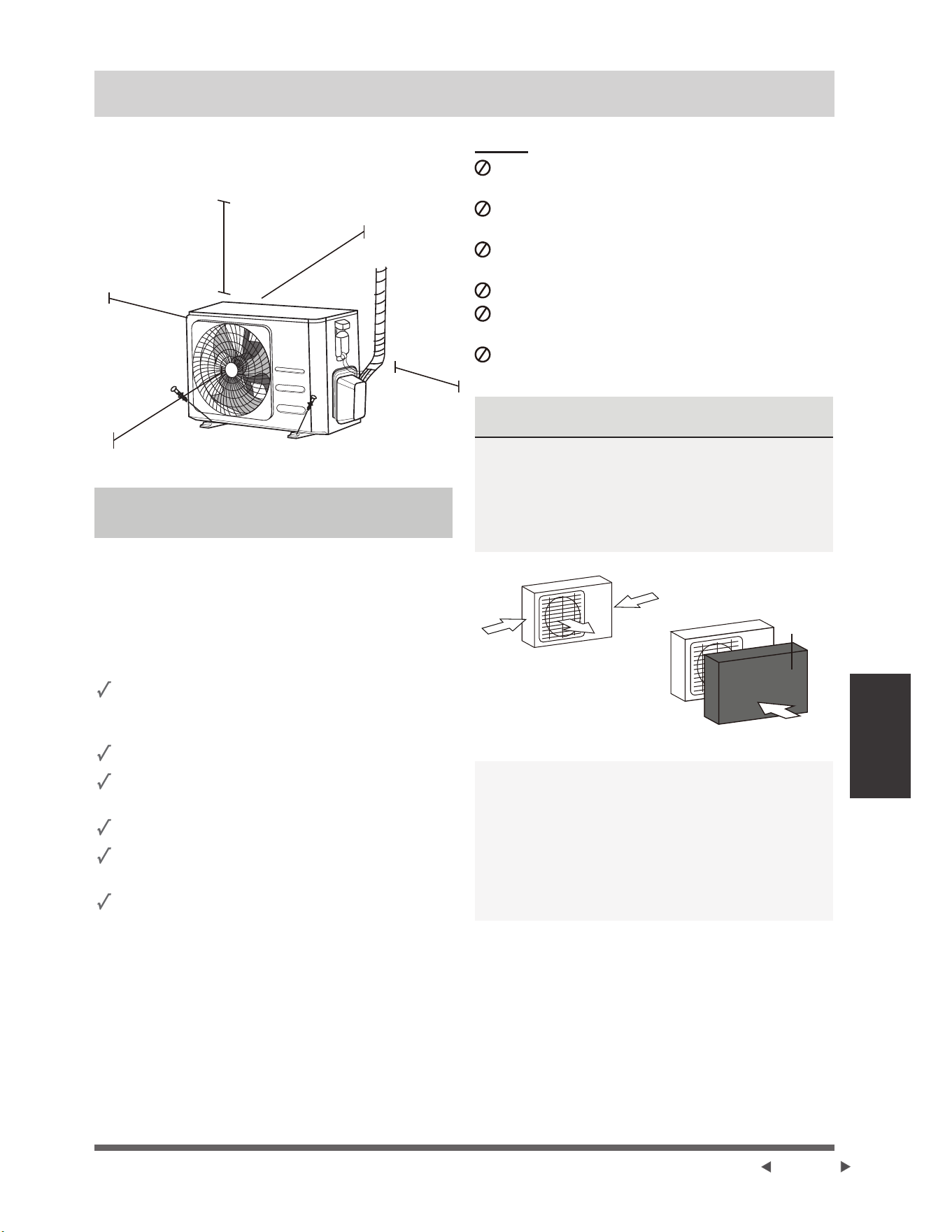
Installation de
l’unité extérieure
sur
Installation de l’unité extérieure
Installez l’unité en respectant les codes et les
UpJOHPHQWDWLRQVORFDOHVLOSHXW\DYRLUGHVGLIIpUHQFHV
entre les régions différentes.
FPSRXFHV
jJDXFKH
FPSRXFHV
dessus
30cm (12
SRXFHVGX
PXUDUULqUH
60cm
SRXFHV
à droite
200cm (79
SRXFHV
devant
Instructions d’installation - Unité
extérieure
Étape 1: Sélectionnez l’emplacement d’installation
$YDQWG¶LQVWDOOHUO¶XQLWpH[WpULHXUHYRXVGHYH]FKRLVLU
un emplacement approprié. Les normes suivantes vous
aideront à sélectionner un emplacement approprié pour
l’unité.
Emplacement approprié d’installation doit répondre
aux normes suivantes :
Répondez à toutes les exigences spatiales
LQGLTXpHVGDQVODVHFWLRQ(VSDFHUHTXLVSRXU
l’installation ci-dessus.
Bonne circulation d’air et ventilation
Ferme et solide — l’emplacement peut supporter
l’unité et ne vibrera pas
Le bruit de l’unité ne dérangera pas les autres
3URWpJpFRQWUHOHVORQJXHVSpULRGHVGHOXPLqUH
directe du soleil ou de pluie
/RUVTXHGHVFKXWHVGHQHLJHVRQWSUpYXHV
SUHQH]OHVPHVXUHVDSSURSULpHVSRXUpYLWHU
ODFFXPXODWLRQGHJODFHHWOHVGRPPDJHVDX[
VHUSHQWLQV
NE PAS installer l’unité dans les endroits suivants:
3UqVG¶XQREVWDFOHTXLEORTXHUDOHVHQWUpHVHWOHV
sorties d’air
3UqVG¶XQHUXHSXEOLTXHGH]RQHVVXUSHXSOpHVRX
G¶XQHQGURLWROHEUXLWGHO¶XQLWpGpUDQJHOHVDXWUHV
3UqVG¶DQLPDX[RXGHSODQWHVTXLVHURQW
HQGRPPDJpVSDUODGpFKDUJHG¶DLUFKDXG
3UqVGHWRXWHVRXUFHGHJD]FRPEXVWLEOH
'DQVXQHQGURLWH[SRVpjGHJUDQGHVTXDQWLWpVGH
SRXVVLqUH
'DQVXQHQGURLWH[SRVpjXQHTXDQWLWpH[FHVVLYH
d’air salé
CONSIDÉRATIONS SPÉCIALES POUR LE TEMPS
EXTRÊME
Si l’unité est exposée à un vent violent :
,QVWDOOH]O¶XQLWpGHVRUWHTXHO¶H[WUDFWHXUG¶DLUVRLWj
XQDQJOHGHSDUUDSSRUWDXYHQW6LQpFHVVDLUH
LQVWDOOH]XQHEDUULqUHGHYDQWO¶XQLWpSRXUOHSURWpJHU
des vents extrêmement violents.
9RLUOHV¿JXUHVFLGHVVRXV
Vent
fort
Vent fort
Vent fort
'pÀHFWHXU
de vent
Si l’unité est fréquemment exposée à de fortes
pluies ou à la neige :
Construisez un abri au-dessus de l’unité pour la
protéger de la pluie ou de la neige. Veillez à ne pas
obstruer le flux d’air autour de l’unité.
Si l’unité est fréquemment exposée à l’air salé
bord de la mer :
Utilisez l’unité extérieure spécialement conçue pour
résister à la corrosion.
Page 21
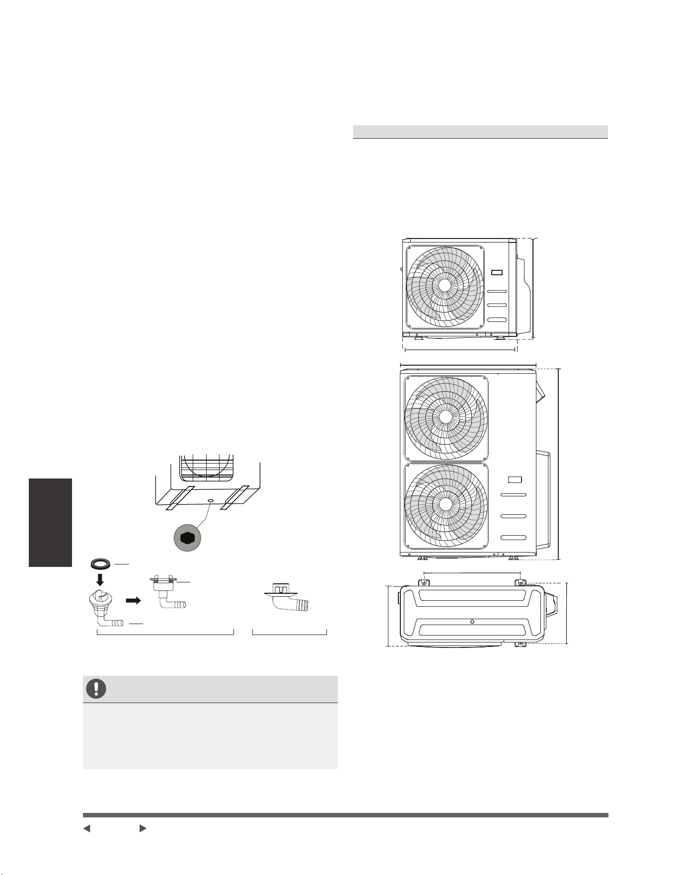
Installation de
l’unité extérieure
sur
Étape 2: Installez le joint de drainage
Unité de pompe à chaleur uniquement
$YDQWGHYLVVHUO¶XQLWpH[WpULHXUHHQSODFHYRXVGHYH]
installer le joint de drainage au bas de l’unité. Il faut
QRWHUTX¶LOH[LVWHGHX[W\SHVGLIIpUHQWVGHMRLQWVGH
drainage en fonction du type d’unité extérieure.
Si le joint de drainage est livré avec un joint en
caoutchouc voir la Figure A, procédez comme
suit:
,QVWDOOH]OHMRLQWHQFDRXWFKRXFjO¶H[WUpPLWpGXMRLQW
GHGUDLQDJHTXLVHFRQQHFWHUDjO¶XQLWpH[WpULHXUH
2. Insérez le joint de drainage dans le trou du plateau
inférieur de l’unité.
7RXUQH]OHMRLQWGHGUDLQDJHGHMXVTX¶jFHTX¶LO
est coincé en place face à l’avant de l’unité.
4. Connectez une rallonge de tuyau de drainage (non
IRXUQLHDXMRLQWGHGUDLQDJHSRXUUHGLULJHUO¶HDXGH
O¶XQLWpHQPRGHGHFKDXIIDJH
Si le joint de drainage ne vient pas avec un joint en
caoutchouc voir la Figure B, procédez comme suit
: B , procédez comme suit :
1. Insérez le joint de drainage dans le trou du plateau
inférieur de l’unité. Le joint de drainage est coincé en
place.
2. Connectez une rallonge de tuyau de drainage (non
IRXUQLHDXMRLQWGHGUDLQDJHSRXUUHGLULJHUO¶HDXGH
O¶XQLWpHQPRGHGHFKDXIIDJH
(A) (B)
Joint
Joint
Trou du plateau inférieur
de l’unité extérieure
Joint de drainage
SOUS CLIMAT FROID
6RXVFOLPDWIURLGDVVXUH]YRXVTXHOHWX\DXGH
GUDLQDJHHVWDXVVLYHUWLFDOTXHSRVVLEOHSRXUDVVXUHU
un drainage rapide de l’eau. Si l’eau s’écoule trop
OHQWHPHQWHOOHSHXWJHOHUGDQVOHWX\DXHWLQRQGHU
l’unité.
Étape 3: Fixez l’unité extérieure
L’unité extérieure peut être ancrée au sol ou à un
VXSSRUWPXUDODYHFERXORQ03UpSDUH]ODEDVH
d’installation de l’unité conformément aux dimensions
ci-dessous.
DIMENSIONS DE MONTAGE DE L’UNITÉ
Vous trouverez ci-dessous une liste des différentes
dimensions d’unités extérieures et de la distance entre
leurs pieds de montage. Préparez la base d’installation
de l’unité conformément aux dimensions ci-dessous.
Types et Spécifications de l’Unité Extérieure
Unité Extérieure de Type Split
A
B
D
W
H
W
H
Page 22
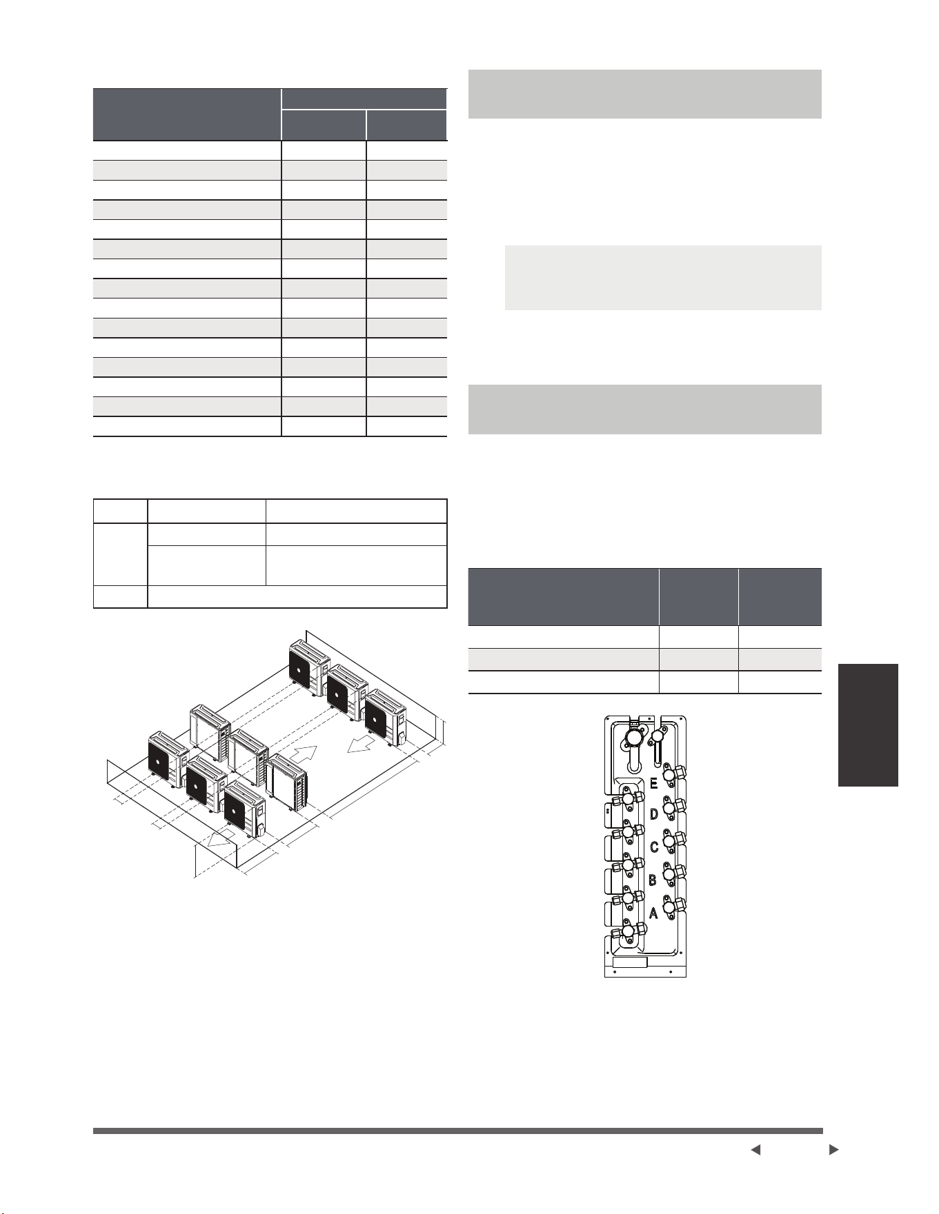
Installation de
l’unité extérieure
sur
Unité : mm/pouce
Dimensions de l’unité
extérieure mm
L x H x L
Dimensions de montage
Distance A Distance B
[[[[
[[[[
[[[[
[[[[
[[[[
[[[[
[[[[
[[[[
[[[[
[[[[
[[[[
[[[[
[[[[
[[[[
[[[[
Rangées d’installation en série
Les relations entre H, A et L sont les suivantes.
LA
/+
/+ FPSRXFHVRXSOXV
+/+
FPSRXFHVRX
plus
/!+ Ne peut pas être installé
L
H
A
300 cm / 118 pouces ou plus
FP
pouces ou
plus
FP
pouces ou
plus
150 cm / 59
pouces ou
plus
FP
pouces ou
plus
Notes sur le Trou de Forage dans le
Mur
Vous devez percer un trou dans le mur pour le tuyau
GHUpIULJpUDQWHWOHFkEOHGHVLJQDOTXLUHOLHUDOHVXQLWpV
intérieurs et extérieurs.
1. Déterminez l’emplacement du trou sur le mur en
fonction de l’emplacement de l’unité extérieure.
¬O¶DLGHG¶XQHSHUFHXVHGHPPSRXFHV
percez un trou dans le mur.
NOTE : /RUVGHSHUFHUOHWURXVXUOHPXU
DVVXUH]YRXVG¶pYLWHUOHV¿OVODSORPEHULHHW
les autres composants sensibles.
3ODFH]OHPDQFKRQGHSURWHFWLRQGDQVOHWURX
&HODSURWqJHOHVERUGVGXWURXHWDLGHjOHVFHOOHU
jOD¿QGXSURFHVVXVG¶LQVWDOODWLRQ
Lors de la sélection d’une unité
intérieure de 24K
/¶XQLWpLQWpULHXUH.QHSHXWrWUHFRQQHFWpHTX¶DYHF
XQV\VWqPH$6¶LO\DGHX[XQLWpVLQWpULHXUHVGH.
HOOHVSHXYHQWrWUHFRQQHFWpHVDX[V\VWqPHV$HW%
Taille des tuyaux de raccordement d’un système A
et B
Unité : pouce
Capacité de l’unité
intérieure
Btu/h
Liquide
Gaz
7K/9K/12K 1/4 3/8
12K/18K 1/4 1/2
24K 3/8 5/8
Page 23
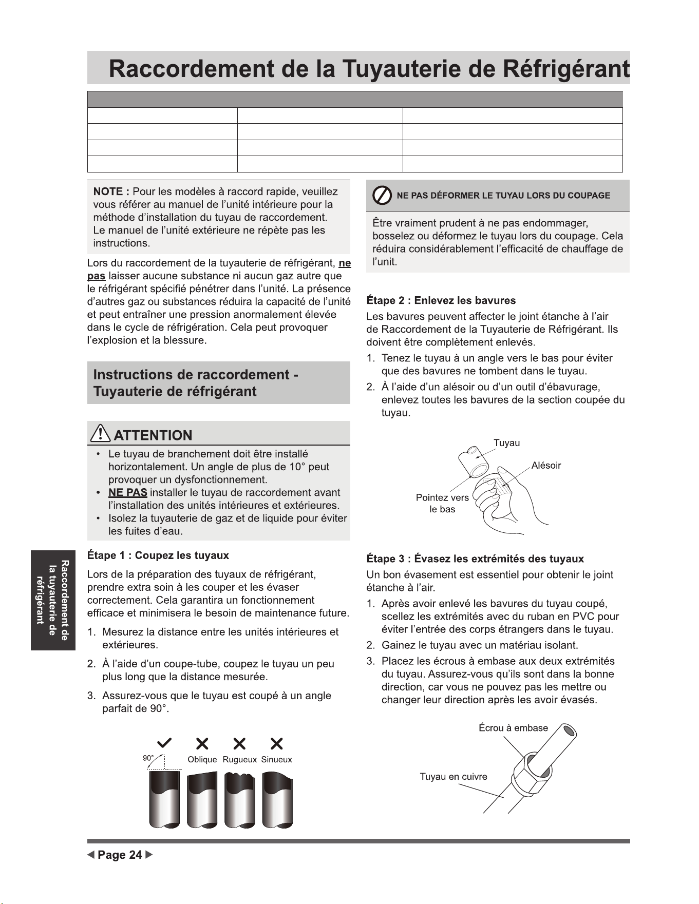
ECR Modèle
MHMZ218DA
MHMZ327DA
MHMZ436DA
MHMZ548DA
2 x Φ6.35 (1/4)
3 x Φ6.35 (1/4)
4 x Φ6.35 (1/4)
5 x Φ6.35 (1/4)
2 x Φ9.52 (3/8)
3 x Φ9.52 (3/8)
3 x Φ9.52 (3/8) + 1 x Φ12.7 (1/2)
3 x Φ9.52 (3/8)+ 2 x Φ12.7 (1/2)
Côté liquide mm(in) Côté gaz mm(in)
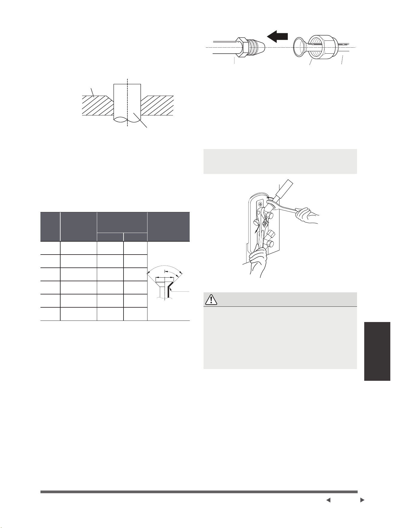
Raccordement de
la tuyauterie de
réfrigérant
4. Enlevez le ruban en PVC des extrémités du
WX\DXORUVTXHYRXVrWHVSUrWjHIIHFWXHUOHWUDYDLO
d’évasement.
5. Fixez la forme d’évasement au bout du tuyau.
L’extrémité du tuyau doit s’étendre au-delà de la
forme d’évasement.
Tuyau
Forme d’évasement
6. Placez l’outil d’évasement sur la forme.
7. Tournez la poignée de l’outil d’évasement dans le
VHQVGHVDLJXLOOHVG¶XQHPRQWUHMXVTX¶jFHTXHOH
WX\DXVRLWFRPSOqWHPHQWpYDVpeYDVH]OHWX\DX
conformément aux dimensions.
EXTENSION DE TUYAUTERIE AU-DELA DU FORME
D’EVASEMENT
Jauge
de
tuyau
Couple de
serrage
Dimension
d’évasement A
Unité : mm/pouce
Forme
d’embase
Min. Max.
18-20 N.m
NJIFP
R0.4~0.8
45
°
±
2
90
°
±
4
A
25-26 N.m
NJIFP
35-36 N.m
NJIFP
45-47 N.m
NJIFP
65-67 N.m
NJIFP
Ø 22
75-85N.m
NJIFP
(QOHYH]O¶RXWLOG¶pYDVHPHQWHWODIRUPHG¶pYDVHPHQW
puis examinez l’extrémité du tuyau pour y déceler
GHV¿VVXUHVHWPrPHXQpYDVHPHQW
Étape 4 : Connectez des tuyaux
Connectez d’abord les tuyaux en cuivre à l’unité
LQWpULHXUHSXLVOHVFRQQHFWH]jO¶XQLWpH[WpULHXUH9RXV
GHYH]G¶DERUGFRQQHFWHUOHWX\DXjEDVVHSUHVVLRQ
SXLVOHWX\DXjKDXWHSUHVVLRQ
/RUVGXUDFFRUGHPHQWGHVpFURXVjHPEDVH
DSSOLTXH]XQH¿QHFRXFKHG¶KXLOHGHUpIULJpUDWLRQ
sur les extrémités évasées des tuyaux.
$OLJQH]OHFHQWUHGHVGHX[WX\DX[TXHYRXV
connecterez.
TuyauTubulure de l’unité intérieure Écrou à embase
3. Serrez à la main l’écrou à embase aussi fermement
TXHSRVVLEOH
¬O¶DLGHG¶XQHFOpSLQFH]O¶pFURXVXUODWXEXOXUHGH
l’unité.
7RXWHQVHUUDQWIHUPHPHQWO¶pFURXVHUUH]O¶pFURX
jHPEDVHjO¶DLGHG¶XQHFOpG\QDPRPpWULTXH
conformément aux valeurs de couple du tableau ci-
dessus.
NOTE : Utilisez une clé plate et une clé
G\QDPRPpWULTXHSRXUFRQQHFWHURXGpFRQQHFWH]OHV
tuyaux à / de l’unité.
ATTENTION
• Assurez-vous d’enrouler l’isolation autour de la
tuyauterie. Un contact direct avec la tuyauterie
QXHSHXWSURYRTXHUGHVEUOXUHVRXGHV
engelures.
• $VVXUH]YRXVTXHOHWX\DXHVWFRUUHFWHPHQW
connecté. Un serrage excessif peut endommager
ODFORFKHHWXQVHUUDJHLQVXI¿VDQWSHXWHQWUDvQHU
des fuites.
Page 25
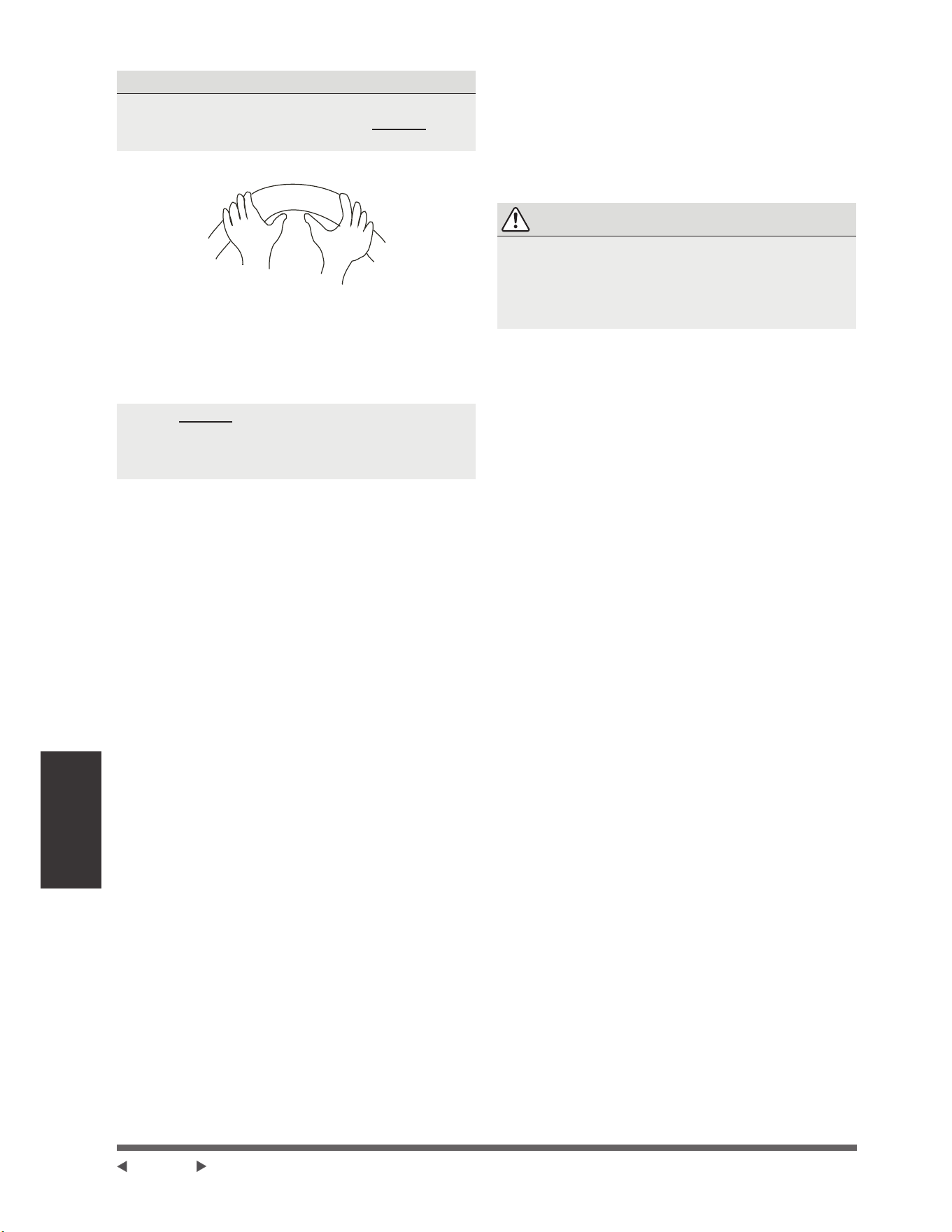
Raccordement de
la tuyauterie de
réfrigérant
NOTES SUR LE RAYON DE COURBURE MINIMUM
3OLH]VRLJQHXVHPHQWODWXEXOXUHDXPLOLHX
FRQIRUPpPHQWDXVFKpPDFLGHVVRXVNE PASplier la
tubulure à plus de 90° ou plus de 3 fois.
Courbez le tuyau avec le pouce
5D\RQPLQFPSRXFHV
$SUqVDYRLUFRQQHFWpOHVWX\DX[HQFXLYUHjO¶XQLWp
LQWpULHXUHHQURXOH]OHFkEOHG¶DOLPHQWDWLRQOHFkEOH
GHVLJQDOHWODWX\DXWHULHDYHFGXUXEDQDGKpVLI
NOTE : NE PAS
entrelacer le câble de signal avec d’autres
fils.
/RUVTXHYRXVUpXQLVVH]FHVpOpPHQWVQ¶HQWUHODFH]
ni croisez le câble de signal avec aucun autre
câblage.
(Q¿OH]FHWX\DXjWUDYHUVOHPXUHWOHFRQQHFWH]j
l’unité extérieure.
,VROH]WRXWHODWX\DXWHULH\FRPSULVOHVYDQQHVGH
l’unité extérieure.
9. Ouvrez les vannes d’arrêt de l’unité extérieure pour
démarrer l’écoulement du réfrigérant entre les unités
intérieure et extérieure.
ATTENTION
9pUL¿H]TX¶LOQ¶\DSDVGHIXLWHGHUpIULJpUDQWXQHIRLV
les travaux d’installation terminés. En cas de fuite
GHUpIULJpUDQWYHQWLOH]LPPpGLDWHPHQWOD]RQHHW
pYDFXH]OHV\VWqPHFRQVXOWH]ODVHFWLRQeYDFXDWLRQ
G¶DLUGHFHPDQXHO
Page 26
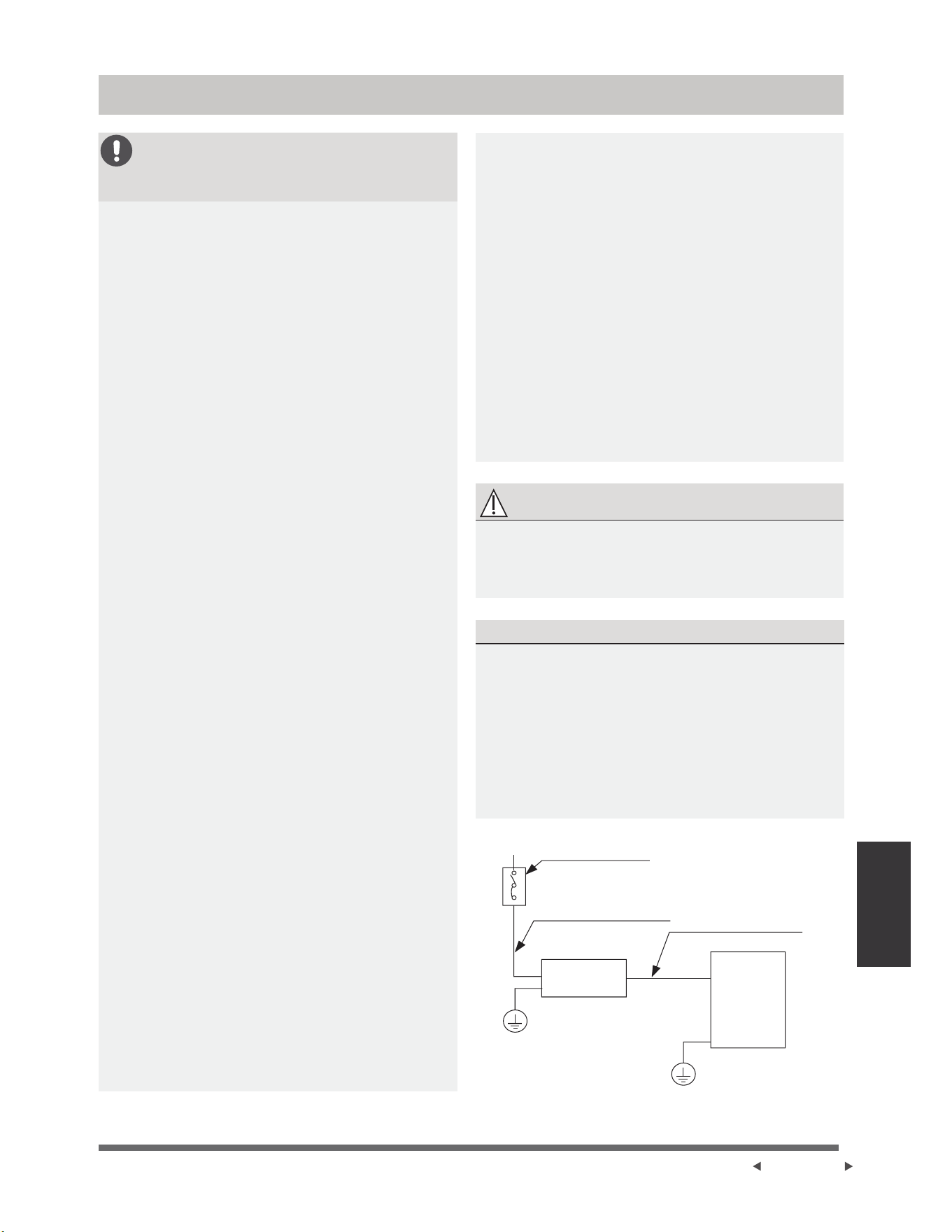
Câblage
AVANT D’EFFECTUER TOUT
TRAVAIL SOUS TENSION, LISEZ
CES RÈGLEMENTS
1. Tout le câblage doit être conforme aux codes
électriques locaux et nationaux et doit être
installé par un électricien agréé.
2.
Tous les raccordements électriques doivent
rWUHHႇHFWXpVFRQIRUPpPHQWDXVFKpPD
de raccordement électrique situé sur les
panneaux des unités intérieures et extérieures.
3. En cas de problème de sécurité grave
avec l’alimentation électrique, arrêtez
immédiatement le travail. Expliquez votre
raisonnement au client et refusez d’installer
l’unité jusqu’à ce que le problème de sécurité
soit correctement résolu.
4. La tension d’alimentation doit être comprise
entre 90% et 110% de la tension nominale.
8QHDOLPHQWDWLRQLQVXႈVDQWHSHXWSURYRTXHU
un dysfonctionnement, un choc électrique ou
un incendie.
5. Si vous connectez l’alimentation au câblage
¿[HLOIDXWLQVWDOOHUXQSDUDIRXGUHHWXQ
interrupteur principal.
6. Si vous raccordez l’alimentation à un câblage
¿[HXQLQWHUUXSWHXURXXQGLVMRQFWHXUTXL
déconnecte tous les pôles et présente une
séparation de contact d’au moins 1/8 pouce
PPGRLWrWUHLQWpJUpDXFkEODJH¿[H/H
WHFKQLFLHQTXDOL¿pGRLWXWLOLVHUXQGLVMRQFWHXU
ou un interrupteur approuvé.
7. Ne branchez l’unité qu’à une prise de
courant individuelle. Ne pas connecter une
autre unité à cette prise.
8. Assurez-vous de bien mettre le climatiseur à
la terre.
9.
&KDTXH¿OGRLWrWUHIHUPHPHQWFRQQHFWp8Q
FkEODJHGHVVHUUpSHXWSURYRTXHUXQHVXUFKDXႇH
du terminal, entraînant un dysfonctionnement du
produit et un risque d’incendie.
10. Ne pas laisser les câbles toucher ou
reposer contre la tubulure de réfrigérant, le
compresseur ou toute pièce mobile dans
l’unité.
6LO¶XQLWpHVWpTXLSpHG¶XQUpFKDXႇHXU
électrique auxiliaire, elle doit être installée
à au moins 1 mètre (40 pouces) de tout
matériau combustible.
12. Pour éviter tout risque de choc électrique, ne
jamais toucher les composants électriques
immédiatement après la mise hors tension.
Après la mise hors tension, attendez toujours
10 minutes ou plus avant de toucher les
composants électriques.
13. Assurez-vous de ne pas croiser le câblage
électrique avec le câblage de signal. Cela
pourrait provoquer des distorsions et des
interférences.
14. L’unité doit être connectée à la prise
principale. Normalement, l’alimentation doit
avoir une impédance de 32 ohms.
15. Aucun autre équipement ne doit être connecté
au même circuit d’alimentation.
16. Connectez les câbles extérieurs avant de
connecter les câbles intérieurs.
AVERTISSEMENT
AVANT LA MISE EN OEUVRE DE TOUT TRAVAIL
ÉLECTRIQUE OU DE CÂBLAGE, VEUILLEZ
COUPER L’ALIMENTATION PRINCIPALE DU
SYSTÈME.
NOTE SUR LE COMMUTATEUR D’AIR
Si le courant maximal du climatiseur dépasse
16A, il faut mettre en place un commutateur d’air
ou un commutateur de protection contre fuite avec
le dispositif de protection (acheté séparément).
Si le courant maximal du climatiseur est moins de
16A, le câble d’alimentation du climatiseur doit
rWUHpTXLSpG¶XQH¿FKHDFKHWpVpSDUpPHQW
Pour le marché nord-américain, elle doit être
câblée selon les exigences du NEC et du CEC.
(A)
Commutateur d’air
(acheté séparément)
Câbles d’alimentation de
l’unité extérieure
(acheté séparément)
Unité
extérieure
Unité
intérieure
Câbles de raccordement
intérieurs & extérieurs
Câblage
Página 27
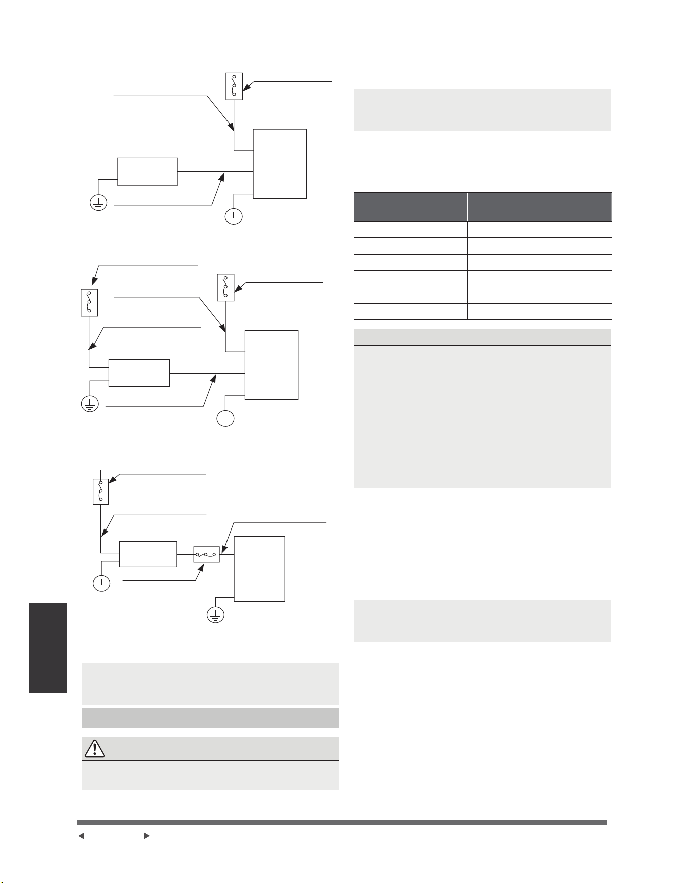
(D)
(B)
(C)
Commutateur d’air
DFKHWp
VpSDUpPHQW
Commutateur d’air
DFKHWpVpSDUpPHQW
Commutateur d’air
DFKHWp
VpSDUpPHQW
Câbles d’alimentation
de l’unité intérieure
Unité
extérieure
Unité
intérieure
Câbles de connexion
pour l’intérieur et
O¶H[WpULHXUDFKHWpV
VpSDUpPHQW
Câbles d’alimentation
de l’unité intérieure
6HXOHPHQWSRXUO$PpULTXHGX1RUG
Câbles d’alimentation de
l’unité extérieure
Unité
extérieure
Câbles de connexion
pour l’intérieur et
O¶H[WpULHXUDFKHWpV
VpSDUpPHQW
Unité
intérieure
Commutateur d’air
DFKHWpVpSDUpPHQW
Commutateur d’air
DFKHWpVpSDUpPHQW
Câbles d’alimentation de
l’unité extérieure
Unité
extérieure
Unité
intérieure
Câbles de connexion
pour l’intérieur et
O¶H[WpULHXUDFKHWpV
VpSDUpPHQW
NOTE : /HVVFKpPDVQHVRQWGHVWLQpVTX¶jGHV¿QV
G¶H[SOLFDWLRQ9RWUHPDFKLQHSHXWrWUHOpJqUHPHQW
différente. La forme réelle prévaut.
Câblage de l’unité extérieure
AVERTISSEMENT
$YDQWG¶HIIHFWXHUWRXWWUDYDLOpOHFWULTXHRXGHFkEODJH
FRXSH]O¶DOLPHQWDWLRQSULQFLSDOHGXV\VWqPH
1. Préparez le câble pour la connexion
D ,OIDXWG¶DERUGFKRLVLUODGLPHQVLRQFRUUHFWHGH
câble. Assurez-vous d’utiliser des câbles H07RN-F.
NOTE : (Q$PpULTXHGX1RUGFKRLVLVVH]OHW\SH
de câble en fonction des codes et réglementations
pOHFWULTXHVORFDX[
Section transversale minimale des
câbles d’alimentation et de signal pour
référence
Courant nominal de
l’appareil A
Section transversale
nominale mmð
!HW
!HW 1
!HW
!HW
!HW 4
!HW 6
CHOISIR LA BONNE TAILLE DU CABLE
/DWDLOOHGXFkEOHG¶DOLPHQWDWLRQGXFkEOHGHVLJQDOGX
fusible et du commutateur nécessaires est déterminée
par le courant maximal de l’unité. Le courant
PD[LPXPHVWLQGLTXpVXUODSODTXHVLJQDOpWLTXHVLWXpH
sur le panneau latéral de l’unité. Veuillez référer à
FHWWHSODTXHVLJQDOpWLTXHSRXUFKRLVLUOHERQFkEOHOH
bon fusible ou le bon commutateur.
127((Q$PpULTXHGX1RUGYHXLOOH]FKRLVLU
la bonne taille de câble en fonction de l’intensité
PLQLPDOHGXFLUFXLWLQGLTXpHVXUODSODTXHVLJQDOpWLTXH
de l’unité.
E ¬O¶DLGHG¶XQHSLQFHjGpQXGHUGpQXGH]ODJDLQHHQ
FDRXWFKRXFGHVGHX[H[WUpPLWpVGXFkEOHGHVLJQDO
SRXUIDLUHH[SRVHUHQYLURQFPSRXFHVGH
câble.
c. Dénudez l’isolation des extrémités.
G ¬O¶DLGHG¶XQHSLQFHjVHUWLUOHV¿OVVHUWLVVH]GHV
pattes en U aux extrémités des câbles.
NOTE : /RUVGXUDFFRUGHPHQWGHVFkEOHVVXLYUH
VWULFWHPHQWOHVFKpPDGHFkEODJH¿JXUDQWjO¶LQWpULHXU
GXFRXYHUFOHGXERvWLHUpOHFWULTXH
(B)
(C)
(D)
Câbles d’alimentation
de l’unité intérieure
Commutateur d’air
(acheté séparément)
Unité
extérieure
Unité
intérieure
Câbles de connexion pour
l’intérieur et l’extérieur
(achetés séparément)
Commutateur d’air
(acheté séparément)
Câbles d’alimentation de
l’unité intérieure
Câbles d’alimentation de
l’unité extérieure
Commutateur d’air
(acheté
séparément)
Unité
intérieure
Unité
extérieure
Câbles de connexion pour
l’intérieur et l’extérieur
(achetés séparément)
(Seulement pour l’Amérique du Nord)
Commutateur d’air
(acheté séparément)
Câbles d’alimentation de
l’unité extérieure
Unité
extérieure
Unité
intérieure
Câbles de connexion
pour l’intérieur et
l’extérieur (achetés
séparément)
Commutateur
d’air (acheté
séparément)
Página 28
Câblage
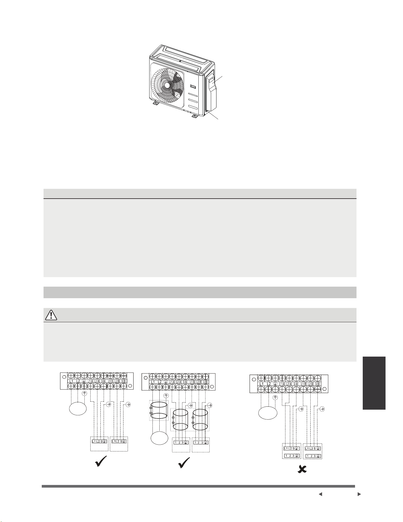
PUISSANCE
VERS A
VERS A VERS B
VERS B
PUISSANCE
PUISSANCE
VERS A VERS B
FACULTATIF
(QOHYH]OHFRXYHUFOHpOHFWULTXHGHO¶XQLWpH[WpULHXUH6¶LOQ¶\DSDVGHFRXYHUFOHVXUO¶XQLWpH[WpULHXUHGpPRQWH]
OHVERXORQVGHODSODTXHGHPDLQWHQDQFHHWHQOHYH]ODSODTXHGHSURWHFWLRQ
Vis
Couverture
&RQQHFWH]OHVFRVVHVDX[ERUQHV)DLWHVFRUUHVSRQGUHOHVFRXOHXUVpWLTXHWWHVGHV¿OVDYHFOHVpWLTXHWWHVGH
ODERvWHjERUQHHWYLVVH]IHUPHPHQWODSDWWHHQ8GHFKDTXH¿OVXUODERUQHFRUUHVSRQGDQWH
4. Fixez le câble avec le serre-câble prévu à cet effet.
,VROH]OHVFkEOHVQRQXWLOLVpVDYHFGXUXEDQpOHFWULTXHeORLJQH]FHVFkEOHVGHVSLqFHVpOHFWULTXHVRX
PpWDOOLTXHV
5pLQVWDOOH]OHFRXYHUFOHGXERvWLHUGHFRPPDQGHpOHFWULTXH
Déclaration des harmoniques
/¶pTXLSHPHQW02%+)14HVWFRQIRUPHjODQRUPH,(&jFRQGLWLRQTXHODSXLVVDQFHGH
FRXUWFLUFXLW6VFVRLWVXSpULHXUHRXpJDOHjDXSRLQWG¶LQWHUIDFHHQWUHO¶DOLPHQWDWLRQGHO¶XWLOLVDWHXU
HWOHV\VWqPHSXEOLF,OHVWGHODUHVSRQVDELOLWpGHO¶LQVWDOODWHXURXGHO¶XWLOLVDWHXUGHO¶pTXLSHPHQWGHV¶DVVXUHU
HQFRQFHUWDWLRQDYHFOHJHVWLRQQDLUHGHUpVHDXGHGLVWULEXWLRQVLQpFHVVDLUHTXHO¶pTXLSHPHQWHVWUDFFRUGp
XQLTXHPHQWjXQHDOLPHQWDWLRQGRQWODSXLVVDQFHGHFRXUWFLUFXLW6VFHVWVXSpULHXUHRXpJDOHj
/¶pTXLSHPHQW02'+)14HVWFRQIRUPHjODQRUPH,(&jFRQGLWLRQTXHODSXLVVDQFHGH
FRXUWFLUFXLW6VFVRLWVXSpULHXUHRXpJDOHjDXSRLQWG¶LQWHUIDFHHQWUHO¶DOLPHQWDWLRQGHO¶XWLOLVDWHXU
HWOHV\VWqPHSXEOLF,OHVWGHODUHVSRQVDELOLWpGHO¶LQVWDOODWHXURXGHO¶XWLOLVDWHXUGHO¶pTXLSHPHQWGHV¶DVVXUHU
HQFRQFHUWDWLRQDYHFOHJHVWLRQQDLUHGHUpVHDXGHGLVWULEXWLRQVLQpFHVVDLUHTXHO¶pTXLSHPHQWHVWUDFFRUGp
XQLTXHPHQWjXQHDOLPHQWDWLRQGRQWODSXLVVDQFHGHFRXUWFLUFXLW6VFHVWVXSpULHXUHRXpJDOHj
Figure du câblage
AVERTISSEMENT
5DFFRUGH]OHVFkEOHVGHFRQQH[LRQDX[ERUQHVWHOOHVTXLGHQWL¿pHVDYHFOHXUVQXPpURVFRUUHVSRQGDQWV
VXUOHERUQLHUGHVXQLWpVLQWpULHXUHHWH[WpULHXUH3DUH[HPSOHODERUQH/$GHOXQLWpH[WpULHXUHGRLWrWUH
FRQQHFWpHjODERUQH/GHOXQLWpLQWpULHXUH/XQLWpH[WpULHXUHSHXWFRUUHVSRQGUHjGLIIpUHQWVW\SHVGXQLWpV
LQWpULHXUHVOHVQXPpURVVXUOHERUQLHUGHOXQLWpLQWpULHXUHSHXYHQWrWUHOpJqUHPHQWGLIIpUHQWV9HXLOOH]SUrWHU
XQHDWWHQWLRQSDUWLFXOLqUHORUVGXFkEODJH
Câblage
Página 29
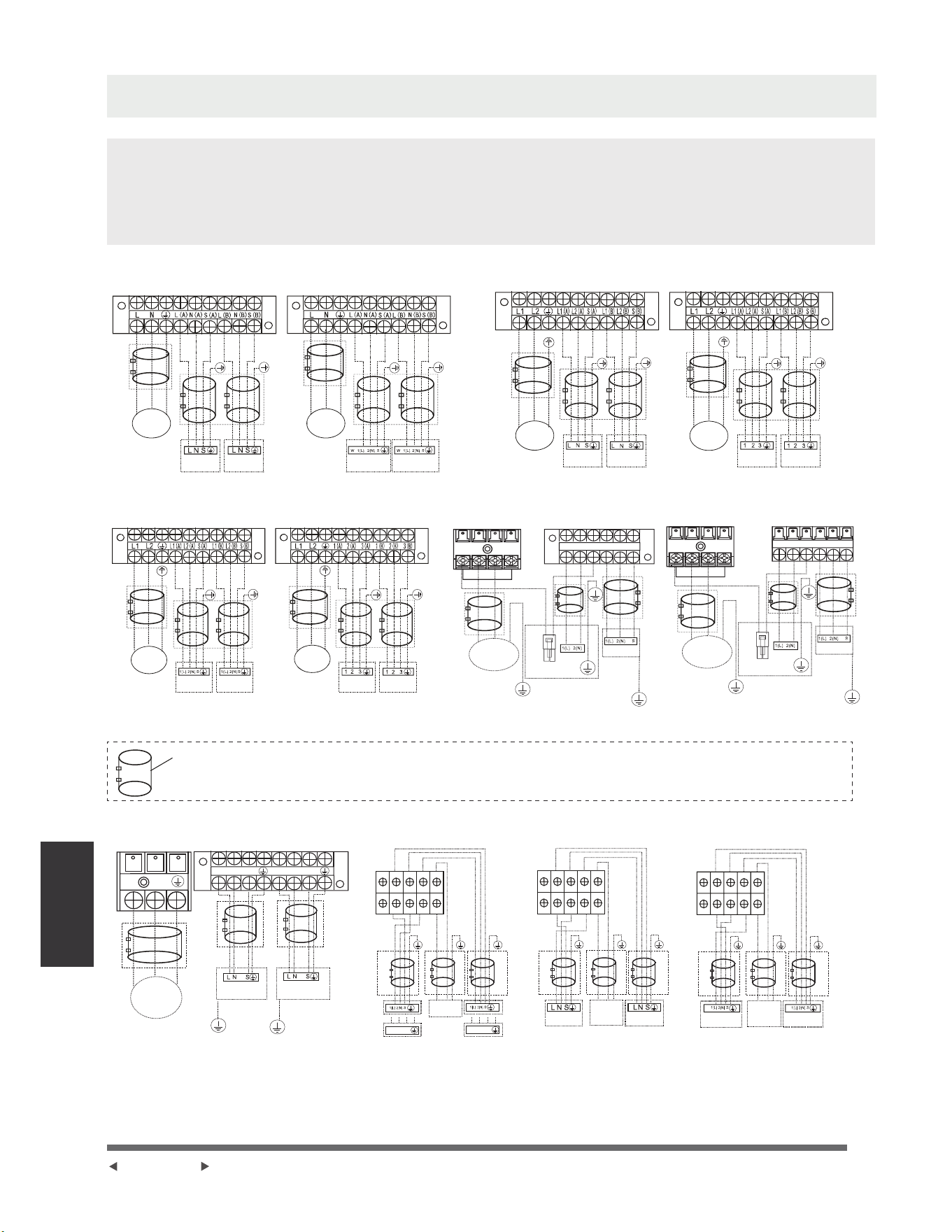
REMARQUE :
Pour les modèles à connecteur rapide, reportez-vous aux Manuel d’Utilisateur &
Manuel d’Installation emballés avec l’unité intérieure.
REMARQUE :
9HXLOOH]YRXVUpIpUHUDX[FKLႇUHVVXLYDQWVVLOHVXWLOLVDWHXUV¿QDX[VRXKDLWHQW
HႇHFWXHUOHXUSURSUHFkEODJH
Faites passer le cordon d’alimentation principal par la sortie de ligne inférieure de
la pince à cordon.
---- Ce symbole indique un câblage de terrain.
Modèles Un-deux:
L(A)
S(A)
N(A)
L(B)
N(B)
S(B)
Y/G
W
L
N
L( 1)
L(A)
S(A)
N(A)
L(B)
N(B)
S(B)
Y/G
W
L
N
L( 1)
PUISSANCE
PUISSANCE
PUISSANCE
PUISSANCE
ALIMENTATION
ALIMENTATION
PUISSANCE
PUISSANCE
VERS A
Modèle A
Modèle E
Modèle B
Modèle F
Modèle C
Modèle G
Modèle D
Modèle H
VERS A
VERS A
VERS A
VERS B
VERS B
VERS B
VERS B
VERS B
VERS B
VERS A VERS B
VERS A
VERS A
VERS A
FACULTATIF
FACULTATIF
FACULTATIF
FACULTATIF
FACULTATIF
FACULTATIF
FACULTATIF
FACULTATIF
FACULTATIF
FACULTATIF
FACULTATIF
FACULTATIF
FACULTATIF
FACULTATIF
FACULTATIF
FACULTATIF
FACULTATIF
FACULTATIF
FACULTATIF
FACULTATIF
FACULTATIF
FACULTATIF
FACULTATIF
VERS B
REMARQUE : Utilisez l’anneau magnétique (non fourni, pièce optionnelle) pour accrocher
le câble de connexion des unités intérieures et extérieures après l’installation. Un anneau
magnétique est utilisé pour un câble.
S(B)
N(A)
N(B)
L(B)
L
L(A)
N
S(A)
1(L) 2(N) 3(S)
1(L) 2(N) 3(S)
S(2)
S(1)
Y/G
L(A)
N(A)
S(A)
L(B)
N(B)
S(B)
N
L
Y/G
S(B)
N(A)
N(B)
L(B)
L
L(A)
N
S(A)
S(2)
S(1)
W
W
S(B)
N(A)
N(B)
L(B)
L
L(A)
N
S(A)
S(2)
S(1)
ALIMENTATION
Modèle I Modèle J Modèle K Modèle L
VERS A VERS B
FACULTATIF
FACULTATIF
FACULTATIF
FACULTATIF
FACULTATIF
FACULTATIF
FACULTATIF
FACULTATIF
FACULTATIF
FACULTATIF
FACULTATIF
FACULTATIF
ALIMENTATION
ALIMENTATION
ALIMENTATION
VERS A
VERS B
VERS B VERS BVERS A VERS A
Página 30
Câblage
ou ou
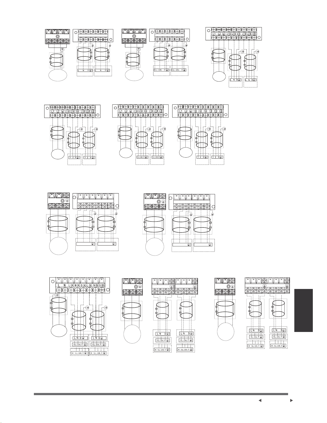
L(A)
S(A)
N(A)
L(B)
N(B)
S(B)
:
/
1
/
1(A)
3(A)
2(A)
1(B)
2(B)
3(B)
L(A)
S(A)
N(A)
L(B)
N(B)
S(B)
:
/
1
/
/$ 1$ 6$
/% 1% 6%
L1 L2
L N
L N
/$ 1$ 6$
/% 1% 6%
1 2 3 1 2 3
1 2 31 2 3
L1(A)
S(A)
L2(A)
L1(B)
L2(B)
S(B)
L1 L2
ALIMENTATION
ALIMENTATION
ALIMENTATION
ALIMENTATION
ALIMENTATION
ALIMENTATION
FACULTATIF
FACULTATIF
FACULTATIF
FACULTATIF
FACULTATIF
FACULTATIF
FACULTATIF
FACULTATIF
FACULTATIF
FACULTATIF
FACULTATIF
FACULTATIF
FACULTATIF
FACULTATIF
FACULTATIF
FACULTATIF
FACULTATIF
FACULTATIF
FACULTATIF
FACULTATIF
FACULTATIF
FACULTATIF
FACULTATIF
FACULTATIF
FACULTATIF
FACULTATIF
FACULTATIF
FACULTATIF
FACULTATIF
FACULTATIF
FACULTATIF
FACULTATIF
FACULTATIF
PUISSANCE
PUISSANCE
PUISSANCE
PUISSANCE
PUISSANCE
Modèle M
Modèle P
Modèle S
Modèle U Modèle V Modèle W
Modèle T
Modèle N
Modèle Q
Modèle O
Modèle R
VERS A VERS B
VERS A VERS B
VERS A VERS B
VERS A VERS B
VERS A VERS B
VERS A VERS B
VERS A
VERS A
VERS B
VERS B
Vers l’unité
intérieure A
Vers l’unité
intérieure A
Vers l’unité
intérieure A
Vers l’unité
intérieure B
Vers l’unité
intérieure B
Vers l’unité
intérieure B
Câblage
Página 31
ou
ou
ou
ou
ou
ou
ou
ou
ou
ou
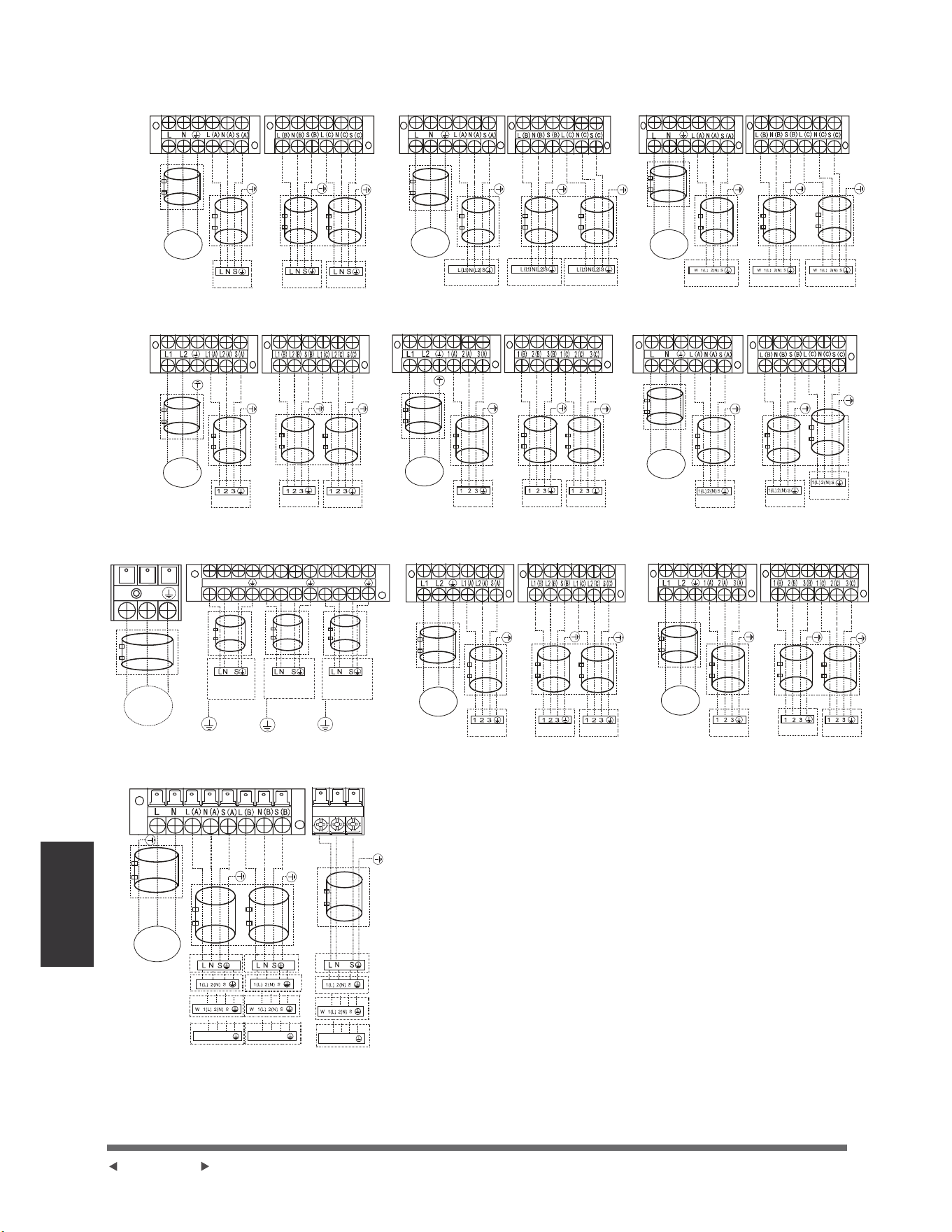
1(L) 2(N) 3(S)
1(L) 2(N) 3(S)
1(L) 2(N) 3(S)
<*
<*
/$
1$
6$
/%
1%
6%
/&
1&
6&
N
L
<*
/& 1& 6&
Modèle A
Modèle D
Modèle G
Modèle J
Modèle B
Modèle E
Modèle H
Modèle C
Modèle F
Modèle I
PUISSANCE
PUISSANCE
PUISSANCE
PUISSANCE
PUISSANCE
PUISSANCE
PUISSANCE PUISSANCE
PUISSANCE
ALIMENTATION
FACULTATIF
FACULTATIF
FACULTATIF
FACULTATIF
FACULTATIF
FACULTATIF
FACULTATIF
FACULTATIF
FACULTATIF
FACULTATIF
FACULTATIF
FACULTATIF
FACULTATIF
FACULTATIF
FACULTATIF
FACULTATIF
FACULTATIF
FACULTATIF
FACULTATIF
FACULTATIF
FACULTATIF
FACULTATIF
FACULTATIF
FACULTATIF
FACULTATIF
FACULTATIF
FACULTATIF
FACULTATIF
FACULTATIF
FACULTATIF
FACULTATIF
FACULTATIF
FACULTATIF
FACULTATIF
FACULTATIF
FACULTATIF
FACULTATIF
FACULTATIF
FACULTATIF
FACULTATIF
VERS A VERS B VERS C
VERS A VERS B VERS C VERS A VERS B VERS C
VERS A VERS B
VERS C
VERS A VERS B VERS C
VERS A VERS B VERS C
VERS A VERS B VERS C
VERS A VERS B VERS C VERS A VERS B VERS C
Vers l’unité
intérieure A
Vers l’unité
intérieure B
Vers l’unité
intérieure C
Modèles Un-trois :
Página 32
Câblage
ou
ou
ou
ou
ou
ou
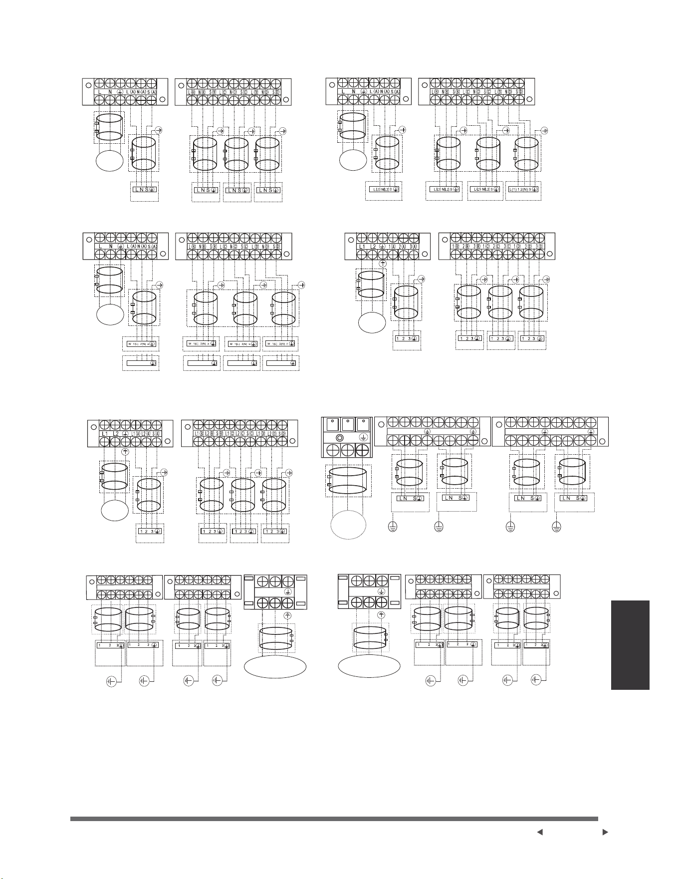
Modèles Un-quatre:
<*
/$
1$
6$
/%
1%
6%
N
L
<*
<*
/&
1&
6&
/'
1'
6'
<*
L2
L1
$
$
$
%
%
%
&
&
&
'
'
'
L2
L1
/$
/$
6$
/%
/%
6%
/&/&6& /'/'6'
1(L) 2(N) 3(S) 1(L) 2(N) 3(S) 1(L) 2(N) 3(S) 1(L) 2(N) 3(S)
Modèle A
Modèle C
Modèle E
Modèle G
Modèle F
Modèle H
Modèle B
Modèle D
ALIMENTATION
ALIMENTATIONALIMENTATION
PUISSANCE
PUISSANCE
PUISSANCE
PUISSANCE
PUISSANCE
VERS A VERS B VERS C VERS D
VERS A VERS B VERS C VERS D
VERS A VERS B VERS C VERS D
VERS A VERS B VERS C VERS D VERS A VERS B VERS C VERS D
VERS A VERS B VERS A VERS B
VERS A VERS B VERS C VERS D
VERS A VERS B VERS C VERS D
FACULTATIF
FACULTATIF
FACULTATIF
FACULTATIF
FACULTATIF
FACULTATIF
FACULTATIF
FACULTATIF
FACULTATIF
FACULTATIF
FACULTATIF
FACULTATIF
FACULTATIF
FACULTATIF
FACULTATIF
FACULTATIF
FACULTATIF
FACULTATIF
FACULTATIF
FACULTATIF
FACULTATIF
FACULTATIF
FACULTATIF
FACULTATIF
FACULTATIF
FACULTATIF
FACULTATIF
FACULTATIF
FACULTATIF
FACULTATIF
FACULTATIF
FACULTATIF
FACULTATIF
FACULTATIF
FACULTATIF
FACULTATIF
FACULTATIF
FACULTATIF
FACULTATIF
FACULTATIF
Câblage
Página 33
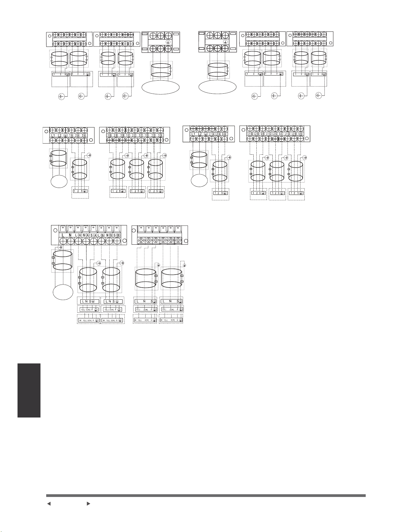
L1(C)L2(C)S(C) L1(D)L2(D)S(D)
L2
L1
1(A)
2(A)
3(A)
1(B)
2(B)
3(B)
1(C)
2(C)
3(C)
1(D)
2(D)
3(D)
L2
L1
L1(A)
L2(A)
S(A)
L1(B)
L2(B)
S(B)
L(C)
S(C)
N(C)
L(D)
N(D)
S(D)
Vers l’unité
intérieure A
Vers l’unité
intérieure B
Vers l’unité
intérieure C
Vers l’unité
intérieure D
FACULTATIF
FACULTATIF
FACULTATIF
FACULTATIF
FACULTATIF
FACULTATIF
FACULTATIF
FACULTATIF
FACULTATIF
FACULTATIF
FACULTATIF
FACULTATIF
FACULTATIF
FACULTATIF
FACULTATIF
FACULTATIF
FACULTATIF
FACULTATIF
FACULTATIF
FACULTATIF
FACULTATIF
FACULTATIF
FACULTATIF
FACULTATIF
FACULTATIF
PUISSANCE
PUISSANCE
PUISSANCE
ALIMENTATION ALIMENTATION
VERS A VERS B VERS C VERS D
VERS A VERS B VERS C VERS D
VERS A VERS B VERS C VERS D
VERS A VERS B VERS C VERS D
Modèle I Modèle J
Modèle LModèle K
Modèle M
Página 34
Câblage
ou
ou
ou
ou
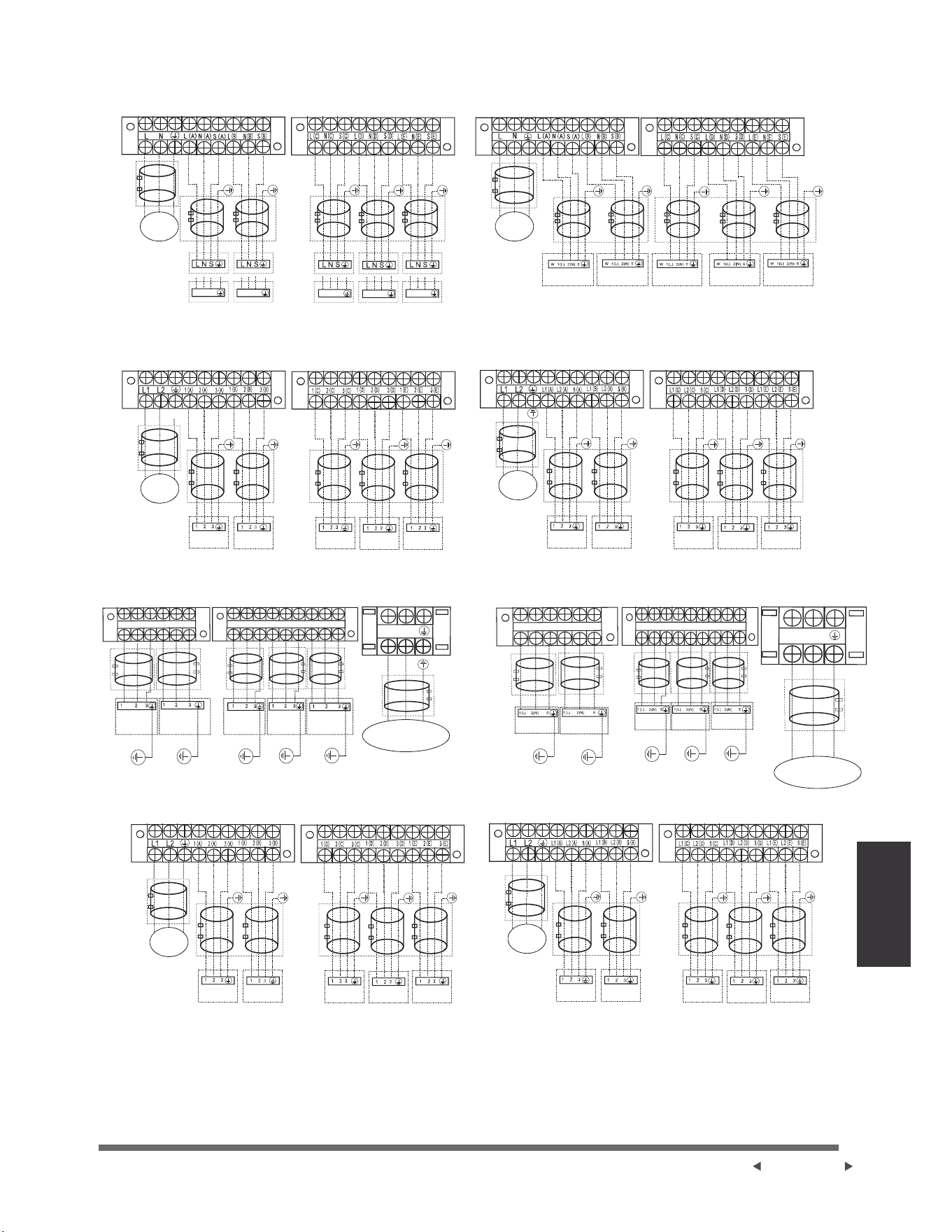
L2
L1
1(A)
2(A)
3(A)
1(B)
2(B)
3(B)
1(C)
2(C)
3(C)
1(D)
2(D)
3(D)
1(E)
2(E)
3(E)
L(C)
N(C)
S(C)
L(D)
N(D)
S(D)
L(E)
N(E)
S(E)
L(A)
N(A)
S(A)
L(B)
N(B)
S(B)
N
L
1(L) 2(N) 3(S) 1(L) 2(N) 3(S)
1(L) 2(N) 3(S)
1(L) 2(N) 3(S)
1(L) 2(N) 3(S)
Modèle A
Modèle C
Modèle E
Modèle G
Modèle D
Modèle F
Modèle H
Modèle B
PUISSANCE
PUISSANCE
PUISSANCE
PUISSANCE
PUISSANCE
PUISSANCE
ALIMENTATION
ALIMENTATION
FACULTATIF
FACULTATIF
FACULTATIF
FACULTATIF
FACULTATIF
FACULTATIF
FACULTATIF
FACULTATIF
FACULTATIF
FACULTATIF
FACULTATIF
FACULTATIF
FACULTATIF
FACULTATIF
FACULTATIF
FACULTATIF
FACULTATIF
FACULTATIF
FACULTATIF
FACULTATIF
FACULTATIF
FACULTATIF
FACULTATIF
FACULTATIF
FACULTATIF
FACULTATIF
FACULTATIF
FACULTATIF
FACULTATIF
FACULTATIF
FACULTATIF
FACULTATIF
FACULTATIF
FACULTATIF
FACULTATIF
FACULTATIF
FACULTATIF
FACULTATIF
FACULTATIF
FACULTATIF
FACULTATIF
FACULTATIF
FACULTATIF
FACULTATIF
FACULTATIF
FACULTATIF
FACULTATIF
FACULTATIF
FACULTATIF
VERS A VERS B VERS C VERS D VERS E
VERS A VERS B VERS C VERS D VERS E
VERS A VERS B VERS C VERS D VERS E
VERS A VERS B VERS C VERS D VERS E
VERS A VERS B VERS C VERS D VERS E VERS A VERS B VERS C VERS D VERS E
VERS A VERS B
VERS C VERS D
VERS E
VERS A VERS B VERS C VERS D VERS E
Modèles Un-cinq:
Câblage
Página 35
ou ou
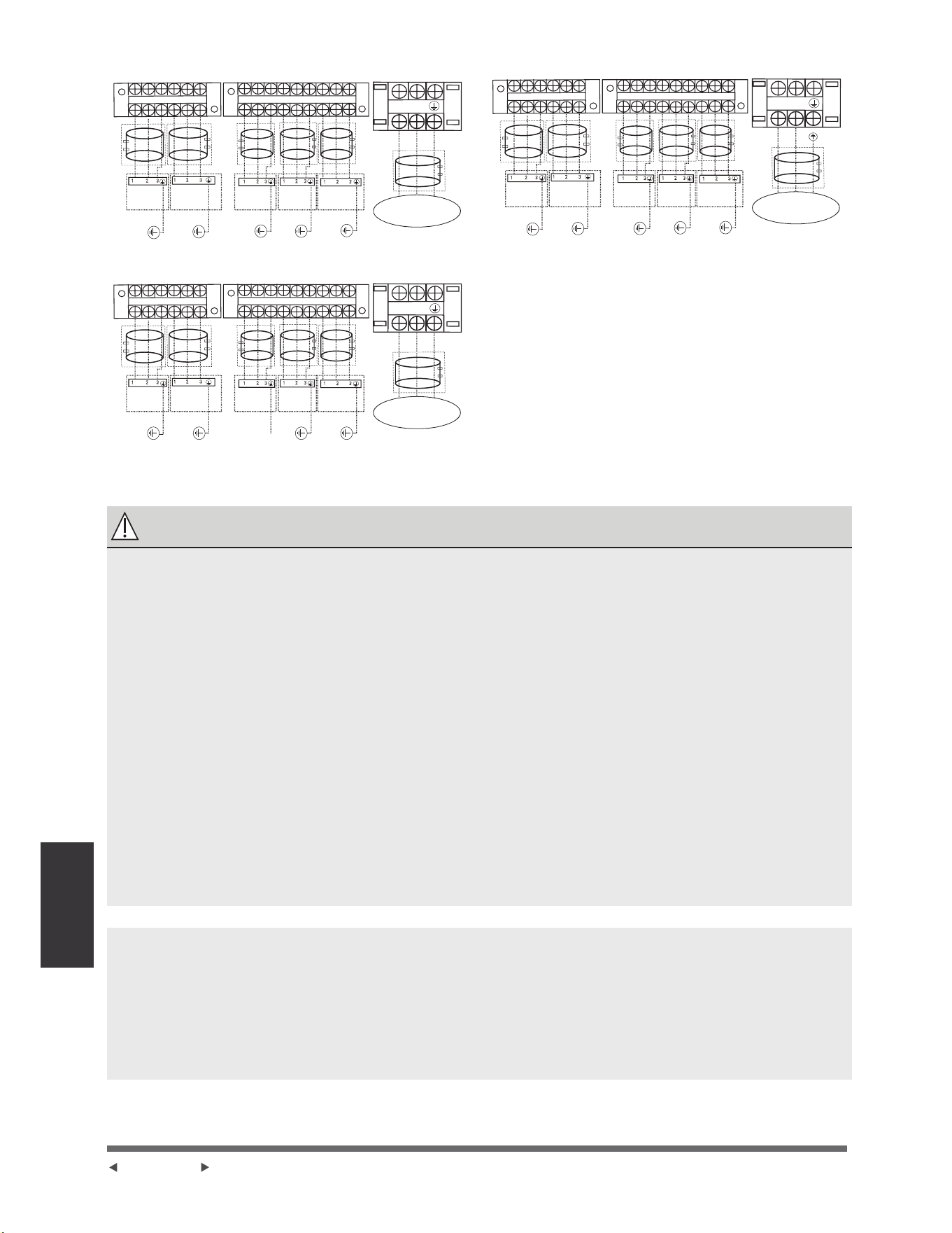
L2
L1
1(A)
2(A)
3(A)
1(B)
2(B)
3(B)
1(C)
2(C)
3(C)
1(D)
2(D)
3(D)
1(E)
2(E)
3(E)
L2
L1
L1(A)
L2(A)
S(A)
L1(B)
L2(B)
S(B)
L1(C)
L2(C)
S(C)
L1(D)
L2(D)
S(D)
L1(E)
L2(E)
S(E)
L2
L1
L1(A)
L2(A)
S(A)
L1(B)L
2(B)
S(B)
L1(C)
L2(C)
S(C)
L1(D)
L2(D)
S(D)
L1(E)
L2(E)
S(E)
ALIMENTATION ALIMENTATION
ALIMENTATION
FACULTATIF FACULTATIF
FACULTATIF FACULTATIF
FACULTATIF FACULTATIF
FACULTATIF FACULTATIF
FACULTATIF FACULTATIF
FACULTATIF
FACULTATIF
FACULTATIF
FACULTATIF
FACULTATIF
FACULTATIF
FACULTATIF FACULTATIF
VERS A VERS B
VERS C VERS DVERS E
VERS A VERS B VERS C VERS D VERS E
VERS A VERS B
VERS C VERS DVERS E
Modèle I Modèle J
Modèle K
ATTENTION
$SUqVDYRLUSULVFRQQDLVVDQFHGHVFRQGLWLRQVFLGHVVXVVXLYH]FHVGLUHFWLYHVORUVTXHYRXVHႇHFWXH]OH
câblage:
3UpYR\H]WRXMRXUVXQFLUFXLWGDOLPHQWDWLRQLQGLYLGXHOVSpFL¿TXHPHQWSRXUOHFOLPDWLVHXU6XLYH]
WRXMRXUVOHVFKpPDGHVFLUFXLWVDႈFKpjO¶LQWpULHXUGXFRXYHUFOHGXFRQWU{OH
/HVYLVTXL¿[HQWOHFkEODJHGDQVOHERvWLHUGHVDSSDUHLOVpOHFWULTXHVSHXYHQWVHGpWDFKHUSHQGDQWOH
WUDQVSRUW&RPPHGHVYLVGHVVHUUpHVSHXYHQWSURYRTXHUGHVEUOXUHVGHFkEOHYpUL¿H]TXHOHVYLV
sont bien serrées.
9pUL¿H]OHVVSpFL¿FDWLRQVGHODVRXUFHG¶DOLPHQWDWLRQ
&RQ¿UPH]TXHODFDSDFLWppOHFWULTXHHVWVXႈVDQWH
&RQ¿UPH]TXHODWHQVLRQGHGpPDUUDJHHVWPDLQWHQXHjSOXVGHGHODWHQVLRQQRPLQDOH
indiquée sur la plaque signalétique.
&RQ¿UPH]TXHO¶pSDLVVHXUGXFkEOHHVWFRQIRUPHDX[VSpFL¿FDWLRQVGHODVRXUFHG¶DOLPHQWDWLRQ
• Installez toujours un disjoncteur de fuite à la terre dans les zones humides ou mouillées.
• Une chute de tension peut avoir les causes suivantes : vibration d’un interrupteur magnétique,
endommagement du point de contact, rupture des fusibles et perturbation du fonctionnement normal.
/DGpFRQQH[LRQG¶XQHDOLPHQWDWLRQpOHFWULTXHGRLWrWUHLQFRUSRUpHGDQVOHFkEODJH¿[H,OGRLW\DYRLU
un espacement des contacts d’au moins 3 mm dans chaque conducteur (de phase) actif.
• Avant d’accéder aux terminaux, tous les circuits d’alimentation doivent être déconnectés.
REMARQUE :
Pour satisfaire à la réglementation EMC obligatoire, qui est exigée par la norme internationale CISPR
$GDQVOHVSD\VRXGLVWULFWVVSpFL¿TXHVYHXLOOH]YRXVDVVXUHUTXHYRXVDSSOLTXH]OHV
anneaux magnétiques corrects sur votre équipement selon le schéma de câblage qui adhère à votre
équipement.
Veuillez contacter votre distributeur ou installateur pour obtenir de plus amples informations et acheter
des anneaux magnétiques (Le fournisseur d’anneaux magnétiques est TDK (modèle ZCAT3035-1330)
ou similaire) .
Página 36
Câblage
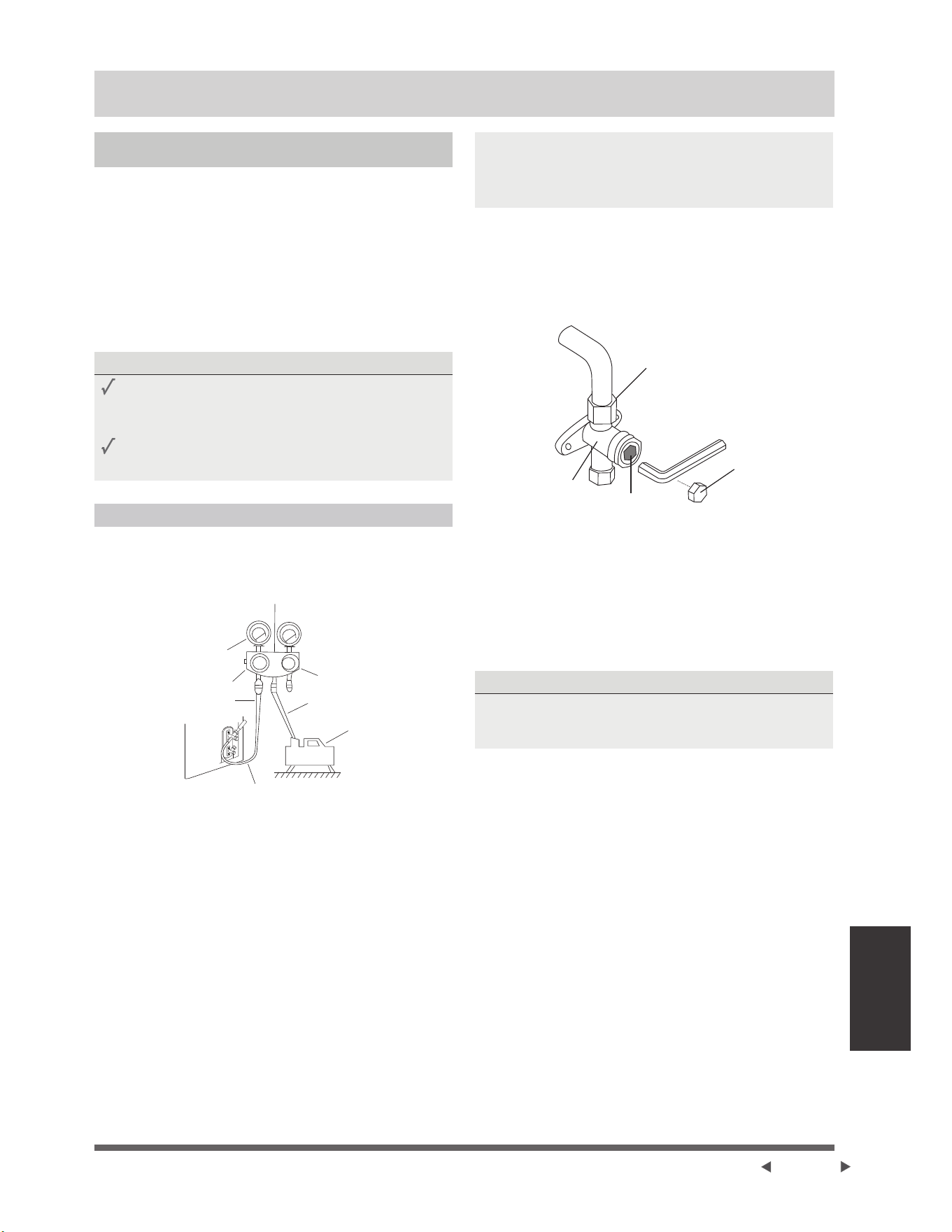
Évacuation d’air
Évacuation d’air
Préparation et précaution
L’air et des corps étrangers dans le circuit de réfrigérant
SHXYHQWSURYRTXHUXQHDXJPHQWDWLRQDQRUPDOHGH
ODSUHVVLRQFHTXLSHXWHQGRPPDJHUOHFOLPDWLVHXU
UpGXLUHVRQHI¿FDFLWpHWFDXVHUGHVEOHVVXUHV8WLOLVH]
une pompe à vide et une jauge manifold pour évacuer
OHFLUFXLWGHUpIULJpUDQWHWHQOHYH]WRXWJD]QRQ
FRQGHQVDEOHVHWO¶KXPLGLWpGDQVOHV\VWqPH
L’évacuation doit être effectuée lors de l’installation
LQLWLDOHHWORUVTXHO¶XQLWpHVWGpSODFp
AVANT D’EFFECTUER L’ÉVACUATION
9pUL¿H]OHVWX\DX[GHFRQQH[LRQHQWUHOHVXQLWpV
LQWpULHXUHHWH[WpULHXUHSRXUDVVXUHTX¶LOVVRQW
correctement connectés.
$VVXUH]YRXVTXHWRXWOHFkEODJHHVWFRUUHFWHPHQW
connecté.
Instructions d’évacuation
$YDQWG¶XWLOLVHUODMDXJHPDQLIROGHWODSRPSHjYLGH
OLVH]OHXUVPDQXHOVG¶XWLOLVDWLRQSRXUYRXVDVVXUHUTXH
vous savez comment les utiliser correctement.
Jauge composée
-76cmHg
7X\DXGHFKDUJH
0DQRPqWUH
7X\DXGHFKDUJH
Pompe à vide
Vanne à basse pression
0DQRPqWUHGHFROOHFWHXU
Vanne à basse
pression
9DQQHjKDXWH
pression
&RQQHFWH]OHWX\DXGHFKDUJHGHODMDXJHPDQLIROG
au port d’entretien de la vanne de basse pression
de l’unité extérieure.
5DFFRUGH]OHWX\DXGHFKDUJHGHODMDXJHGX
collecteur à la pompe à vide.
3. Ouvrir le côté à Basse Pression de la jauge
manifold. Gardez le côté à Haute Pression fermé.
'pPDUUH]ODSRPSHjYLGHSRXUpYDFXHUOHV\VWqPH
5. Fonctionnez le vide pendant au moins de 15
PLQXWHVRXMXVTX¶jFHTXHOHPqWUHFRPSRVp
LQGLTXHFP+*[3D
6. Fermez la vanne à basse pression de la jauge du
collecteur et arrêtez la pompe à vide.
$WWHQGH]PLQXWHVSXLVYpUL¿H]TX¶LOQ¶\DSDVHX
GHFKDQJHPHQWGDQVODSUHVVLRQGXV\VWqPH
NOTE : 6¶LOQ¶\DSDVGHFKDQJHPHQWGHSUHVVLRQ
GDQVOHV\VWqPHGpYLVVH]OHFDSXFKRQGHODYDQQHj
JDUQLWXUHYDQQHjKDXWHSUHVVLRQ6LODSUHVVLRQGX
V\VWqPHFKDQJHLOSHXW\DYRLUXQHIXLWHGHJD]
,QVpUH]XQHFOpKH[DJRQDOHGDQVODYDQQHj
JDUQLWXUHYDQQHKDXWHSUHVVLRQHWRXYUH]ODYDQQH
HQWRXUQDQWODFOpG¶XQTXDUWGHWRXUGDQVOHVHQV
inverse des aiguilles d’une montre. Écoutez le gaz
SRXUVRUWLUGXV\VWqPHSXLVIHUPH]ODYDQQHDSUqV
5 secondes.
Écrou à embase
Corps de
vanne
Tige de
vanne
9. Observez la Jauge de Pression pendant une minute
SRXUYRXVDVVXUHUTX¶LOQ¶\DSDVGHFKDQJHPHQWGH
SUHVVLRQ(OOHGRLWLQGLTXHUXQHSUHVVLRQOpJqUHPHQW
VXSpULHXUHjODSUHVVLRQDWPRVSKpULTXH
(QOHYH]OHWX\DXGHFKDUJHGXSRUWG¶HQWUHWLHQ
¬O¶DLGHG¶XQHFOpKH[DJRQDOHRXYUH]FRPSOqWHPHQW
OHVYDQQHVjKDXWHSUHVVLRQHWjEDVVHSUHVVLRQ
OUVREZ DÉLICATEMENT DE TIGE DE VANNE
/RUVTXHYRXVRXYUH]OHVWLJHVGHYDQQHWRXUQH]OD
FOpKH[DJRQDOHMXVTX¶jFHTX¶HOOHIUDSSHOHERXFKRQ
Ne pas essayer de forcer la vanne à l’ouvrir davantage.
6HUUH]OHVERXFKRQVGHWX\DXjODPDLQSXLVOH
serrez à l’aide de l’outil approprié.
13. Si l’unité extérieure utilise toutes les vannes à vide
HWTXHODSRVLWLRQjYLGHVHWURXYHVXUODYDQQH
SULQFLSDOHOHV\VWqPHQ¶HVWSDVFRQQHFWpjO¶XQLWp
intérieure. La valve doit être serrée à l’aide d’un
pFURX9pUL¿H]O¶DEVHQFHGHIXLWHVGHJD]DYDQW
O¶RSpUDWLRQD¿QG¶pYLWHUOHVIXLWHV
Page 37
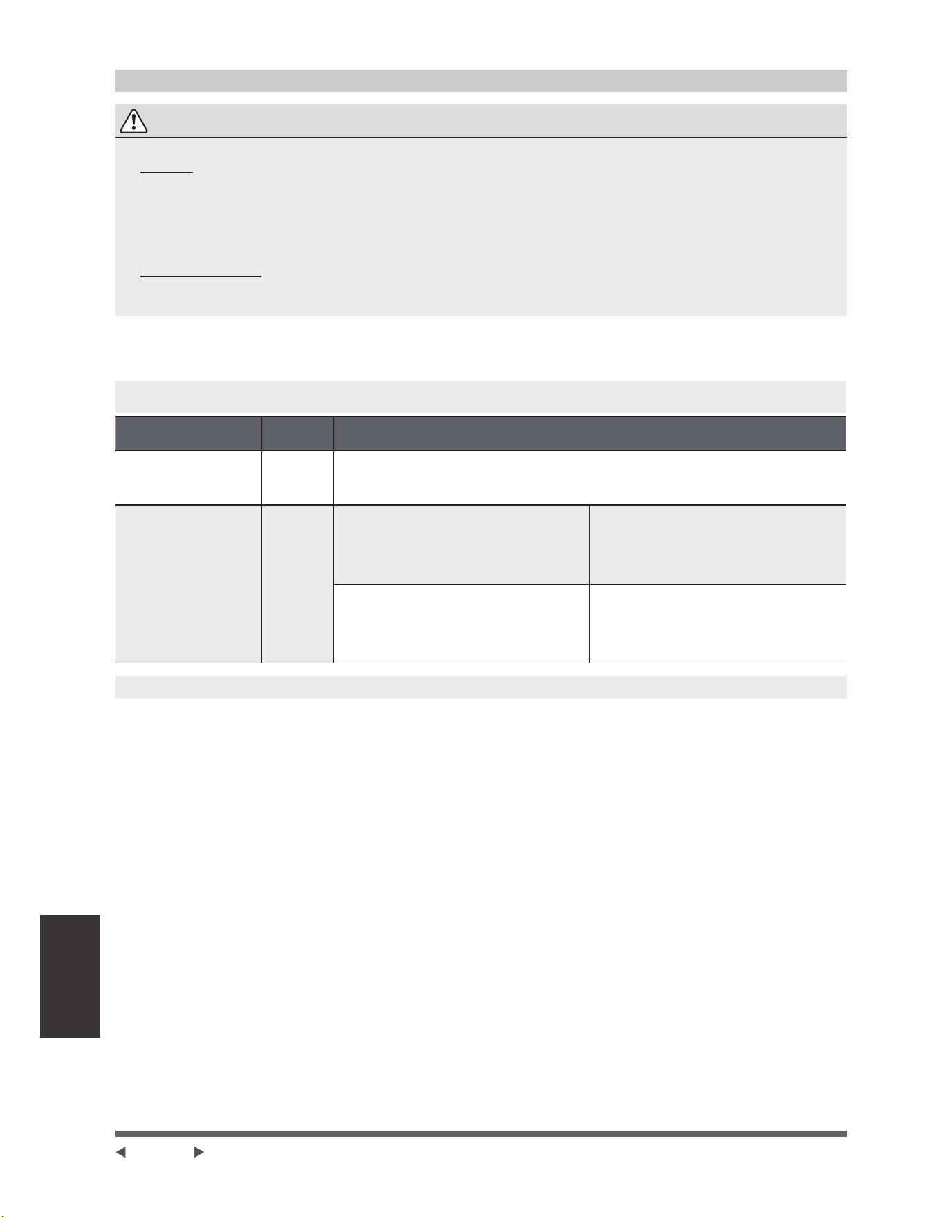
Évacuation d’air
Note relative à l’ajout de réfrigérant
ATTENTION
• /HFKDUJHPHQWGXUpIULJpUDQWGRLWrWUHHIIHFWXpDSUqVOHFkEODJHO¶DVSLUDWLRQHWOHVWHVWVGHIXLWH
• NE PASGpSDVVHUODTXDQWLWpPD[LPDOHDXWRULVpHGHUpIULJpUDQWQLVXUFKDUJHUOHV\VWqPH&HODULVTXHUDLW
d’endommager l’unité ou d’avoir une incidence sur son fonctionnement.
• &KDUJHUDYHFGHVVXEVWDQFHVLQDSSURSULpHVSHXWSURYRTXHUGHVH[SORVLRQVRXGHVDFFLGHQWV$VVXUH]YRXV
TXHOHUpIULJpUDQWDSSURSULpHVWXWLOLVp
• /HVFRQWHQHXUVGHUpIULJpUDQWGRLYHQWrWUHRXYHUWVOHQWHPHQW7RXMRXUVXWLOLVHUXQpTXLSHPHQWGHSURWHFWLRQ
ORUVGXFKDUJHPHQWGXV\VWqPH
• NE PAS mélanger les types de réfrigérants.
• 3RXUOHPRGqOHGHUpIULJpUDQW5RX5DVVXUH]YRXVTXHOHVFRQGLWLRQVGDQVOD]RQHRQWpWpVpFXULVpHV
HQFRQWU{ODQWOHVPDWpULDX[LQIODPPDEOHVORUVTXHOHUpIULJpUDQWHVWDMRXWpDXFOLPDWLVHXU
1 PRGqOHVXQMXPHDX1 PRGqOHVXQWURLV1 PRGqOHVXQTXDWUH1 PRGqOHVXQFLQT(Q
IRQFWLRQGHODORQJXHXUGHODWX\DXWHULHGHUDFFRUGHPHQWRXGHODSUHVVLRQGXV\VWqPHpYDFXpLOIDXWDMRXWHUGX
UpIULJpUDQW5HIHUH]YRXVDXWDEOHDXFLGHVVRXVSRXUFRQQDvWUHOHVTXDQWLWpVGHUpIULJpUDQWjDMRXWHU
RÉFRIGÉRANT SUPPLÉMENTAIRE PAR LONGUEUR DE TUYAU
Longueur du tuyau de
raccordement m
Méthode de
purge d’air
Réfrigérant supplémentaire
Longueur du tuyau de
SUpFKDUJHIWP
(longueur du tuyau de
SUpFKDUJH[1
Pompe à vide N/A
Plus de (longueur du tuyau de
SUpFKDUJH[1IWP
Pompe à vide
&{WpOLTXLGH´
R32
(Longueur totale du tuyau - longueur du tuyau de
SUpFKDUJH[1[JP
(Longueur totale du tuyau - longueur du tuyau de
SUpFKDUJH[1[R=IW
&{WpOLTXLGH´
R32
(Longueur totale du tuyau - longueur du tuyau de
SUpFKDUJH[1[JP
(Longueur totale du tuyau - longueur du tuyau de
SUpFKDUJH[1[R=IW
&{WpOLTXLGH´
R410A
(Longueur totale du tuyau - longueur du tuyau de
SUpFKDUJH[1[JP
(Longueur totale du tuyau - longueur du tuyau de
SUpFKDUJH[1[R=IW
&{WpOLTXLGH´
R410A
(Longueur totale du tuyau - longueur du tuyau de
SUpFKDUJH[1[JP
(Longueur totale du tuyau - longueur du tuyau de
SUpFKDUJH[1[R=IW
NOTE : /DORQJXHXUVWDQGDUGGXWX\DXHVWGHP
Page 38
Évacuation d’air
6HXOHPHQWSRXUOHVPRGqOHVG¶$XVWUDOLH
• NE PAS mélanger les types de réfrigérants.
1 PRGqOHVXQMXPHDX1 PRGqOHVXQWURLV1 PRGqOHVXQTXDWUH1 PRGqOHVXQFLQT&HUWDLQV
V\VWqPHVQpFHVVLWHQWXQHFKDUJHVXSSOpPHQWDLUHHQIRQFWLRQGHODORQJXHXUGXWX\DX/DORQJXHXUVWDQGDUGGX
WX\DXHVWGHP/HUpIULJpUDQWVXSSOpPHQWDLUHjFKDUJHUSHXWrWUHFDOFXOpjO¶DLGHGHODIRUPXOHVXLYDQWH
RÉFRIGÉRANT SUPPLÉMENTAIRE PAR LONGUEUR DE TUYAU
Longueur du tuyau de
raccordement m
Méthode de
purge d’air
Réfrigérant supplémentaire
0RLQVTXH/RQJXHXUVWDQGDUG
du tuyau x N
Pompe à vide N/A
3OXVTXH/RQJXHXUVWDQGDUG
du tuyau x N
Pompe à vide
&{WpOLTXLGH´
(Longueur totale du tuyau - longueur du tuyau de
SUpFKDUJH[1[JP
&{WpOLTXLGH´
(Longueur totale du tuyau - longueur du tuyau de
SUpFKDUJH[1[JP
9HLOOH]jUHWLUHUODFKDUJHGHUpIULJpUDQWVXSSOpPHQWDLUHHQIRQFWLRQGXYROXPHQRPLQDOPGHWX\DXWHULHGH
UpIULJpUDQWORUVTXHYRXVHIIHFWXH]XQWHVWGHYpUL¿FDWLRQGXPDUFKpRXGXJRXYHUQHPHQW
Page 39
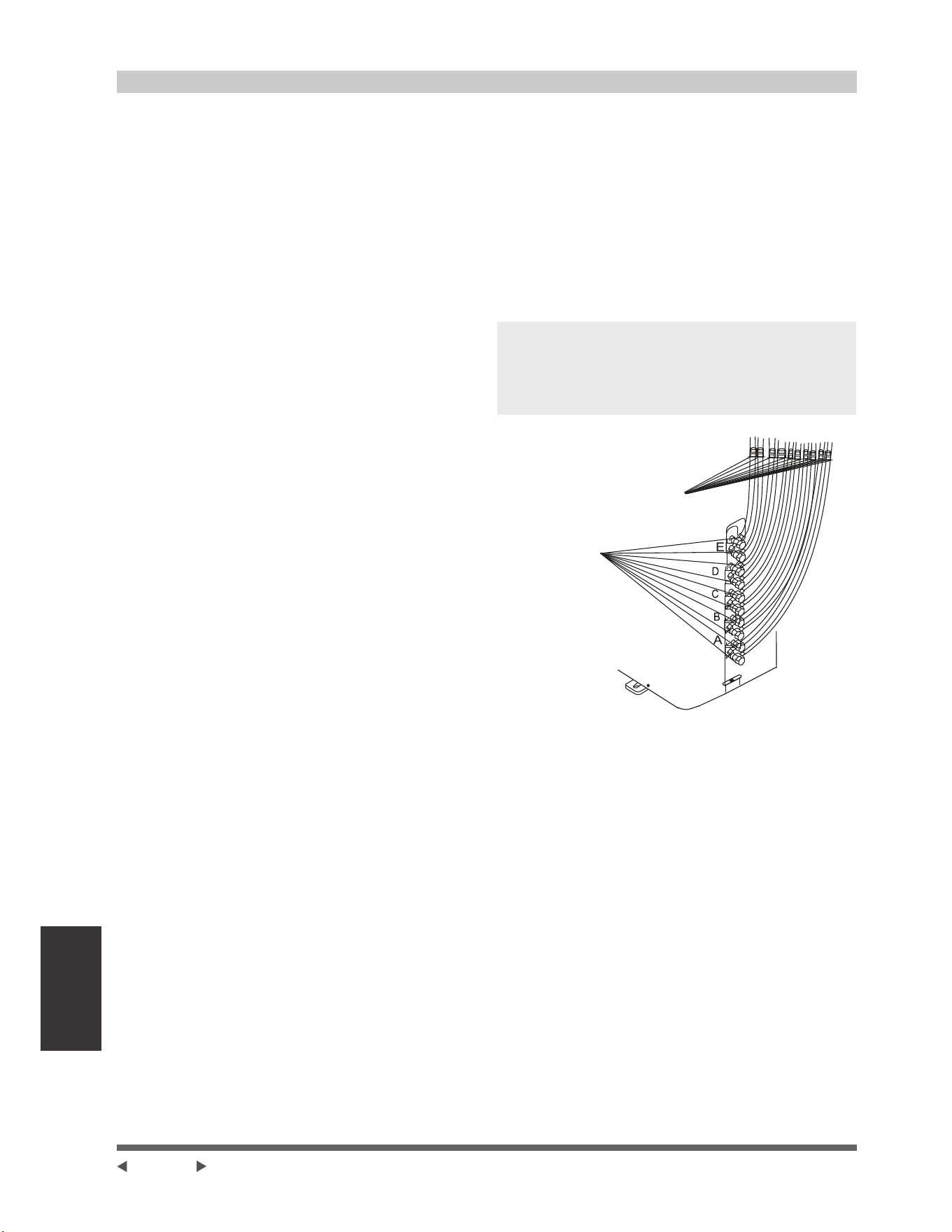
Évacuation d’air
Véri¿cation de la sécurité et des fuites
9pUL¿FDWLRQGHVpFXULWppOHFWULTXH
(IIHFWXH]OHFRQWU{OHGHVpFXULWppOHFWULTXHDSUqVDYRLU
WHUPLQpO¶LQVWDOODWLRQ&RXYUH]OHVGRPDLQHVVXLYDQWV
1. Résistance isolée
/DUpVLVWDQFHLVROpHGRLWrWUHVXSpULHXUHj0ȍ
2. Travaux de mise à la terre
$SUqVDYRLUWHUPLQpOHVWUDYDX[GHPLVHjODWHUUH
mesurez la résistance de mise à la terre par
détection visuelle et à l’aide du testeur de résistance
GHPLVHjODWHUUH$VVXUH]YRXVTXHODUpVLVWDQFH
GHPLVHjODWHUUHHVWLQIpULHXUHjȍ
9pUL¿FDWLRQGHO¶pWDQFKpLWppOHFWULTXHHIIHFWXpH
SHQGDQWOHWHVWORUVTXHO¶XQLWpHVWHQIRQFWLRQQHPHQW
/RUVGXIRQFWLRQQHPHQWGHWHVWPLVHHQVHUYLFH
DSUqVO¶LQVWDOODWLRQWHUPLQpHRQXWLOLVHO¶pOHFWURVRQGH
HWOHPXOWLPqWUHSRXUHIIHFWXHUXQHYpUL¿FDWLRQGHV
IXLWHVpOHFWULTXHVeWHLJQH]LPPpGLDWHPHQWO¶XQLWp
en cas de fuite. Essayez d’évaluer les solutions
GHUHFKDQJHMXVTX¶jFHTXHO¶XQLWpIRQFWLRQQH
correctement.
Vérification des fuite de gaz
0pWKRGHGHO¶HDXVDYRQQHXVH
Utilisez une solution d’eau savonneuse ou un
GpWHUJHQWOLTXLGHQHXWUHVXUOHUDFFRUGGHO¶XQLWp
intérieure ou les raccords de l’unité extérieure avec
XQHEURVVHGRXFHSRXUYpULILHUO¶pWDQFKpLWpGHV
points de raccordement de la tuyauterie. Si des
EXOOHVpPHUJHQWLO\DGHVIXLWHVGHVWX\DX[
2. Détecteur de fuites
Utilisez le détecteur de fuites pour examiner des
fuites.
NOTE : L’illustration est donnée à titre d’exemple
XQLTXHPHQW/¶RUGUHUpHOGH$%&'HW(VXUOD
PDFKLQHSHXWrWUHOpJqUHPHQWGLIIpUHQWGHO¶XQLWpTXH
YRXVDYH]DFKHWpHPDLVODIRUPHJpQpUDOHUHVWHUDOD
même.
Point de contrôle
de l’unité intérieure
Point de
contrôle
de l’unité
extérieure
$%&'VRQWGHVSRLQWVSRXUOHW\SH
$%&'HW(VRQWGHVSRLQWVSRXUOHW\SHXQFLQT
Page 40
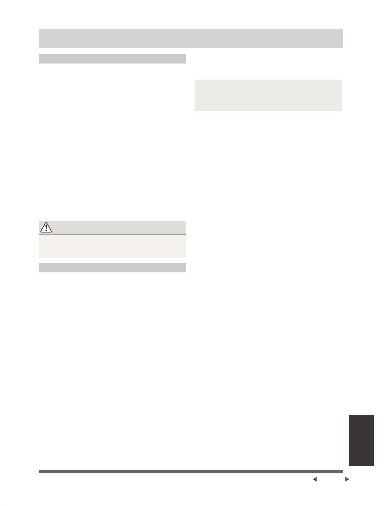
Mise en service
Mise en service
Avant la Mise en service
8QHPLVHHQVHUYLFHGRLWrWUHHIIHFWXpHDSUqV
O¶LQVWDOODWLRQFRPSOqWHGHO¶HQVHPEOHGXV\VWqPH
&RQ¿UPH]OHVSRLQWVVXLYDQWVDYDQWG¶HIIHFWXHUO¶HVVDL
D /HVXQLWpVLQWpULHXUHVHWH[WpULHXUHVVRQW
correctement installées.
E /DWX\DXWHULHHWOHFkEODJHVRQWFRUUHFWHPHQW
connectés.
F 6DQVREVWDFOHVjO¶HQWUpHHWjODVRUWLHGHO¶XQLWpTXL
SRXUUDLHQWSURYRTXHUXQHPDXYDLVHSHUIRUPDQFHRX
un dysfonctionnement du produit. Il n’y pas de fuite
GDQVOHV\VWqPHGHUpIULJpUDWLRQ
H /HV\VWqPHGHGUDLQDJHHVWVDQVEORFDJHHWVH
déverse dans un endroit sûr.
I /¶LVRODWLRQWKHUPLTXHHVWFRUUHFWHPHQWLQVWDOOpH
J /HV¿OVGHPLVHjODWHUUHVRQWFRUUHFWHPHQW
connectés.
K /DORQJXHXUGHODWX\DXWHULHHWODFDSDFLWpGH
VWRFNDJHGXUpIULJpUDQWVXSSOpPHQWDLUHRQWpWp
enregistrées.
L /DWHQVLRQG¶DOLPHQWDWLRQFRUUHVSRQGjODWHQVLRQ
correcte pour le climatiseur.
ATTENTION
Le fait de ne pas effectuer l’essai peut entraîner des
GRPPDJHVjO¶XQLWpGHVGRPPDJHVPDWpULHOVRXGHV
blessures corporelles.
Instructions de Mise en Service
2XYUH]OHVYDQQHVG¶DUUrWGHOLTXLGHHWGHJD]
2. Allumez l’interrupteur d’alimentation principale et
ODLVVH]O¶XQLWpVHUpFKDXIIHU
3. Réglez le climatiseur en mode COOL.
4. Pour l’unité intérieure
$ $VVXUH]YRXVTXHODWpOpFRPPDQGHHWVHV
boutons fonctionnent correctement.
b. Assurez-vous les persiennes fonctionnent
FRUUHFWHPHQWHWSHXYHQWrWUHFKDQJpVjO¶DLGHGH
la télécommande.
F 9pUL¿H]GHQRXYHDXVLODWHPSpUDWXUHDPELDQWH
est correctement enregistrée.
G $VVXUH]YRXVTXHOHVLQGLFDWHXUVGHOD
WpOpFRPPDQGHHWGXSDQQHDXG¶DI¿FKDJHGH
l’unité intérieure fonctionnent correctement.
H $VVXUH]YRXVTXHOHVERXWRQVPDQXHOVGHO¶XQLWp
intérieure fonctionnent correctement.
I 9pUL¿H]TXHOHV\VWqPHGHGUDLQDJHIRQFWLRQQH
sans blocage et s’écoule en douceur.
J $VVXUH]YRXVTX¶LOQ¶\DSDVGHYLEUDWLRQVQLGH
bruit anormal pendant le fonctionnement.
5. Pour l’unité extérieure
D 9pUL¿H]V¶LO\DGHVIXLWHVGDQVOHV\VWqPHGH
réfrigération.
E $VVXUH]YRXVTX¶LOQ¶\DSDVGHYLEUDWLRQVRXGH
bruit anormal pendant le fonctionnement.
F $VVXUH]YRXVTXHOHYHQWOHEUXLWHWO¶HDX
générés par l’unité ne gênent pas vos voisins et
ne présentent aucun danger pour la sécurité.
NOTE : Si l’unité fonctionne mal ou ne fonctionne pas
FRQIRUPpPHQWjYRVDWWHQWHVYHXLOOH]YRXVUHSRUWHU
à la section Dépannage du Manuel Utilisateur avant
G¶DSSHOHUOHVHUYLFHFOLHQWqOH
Page 41
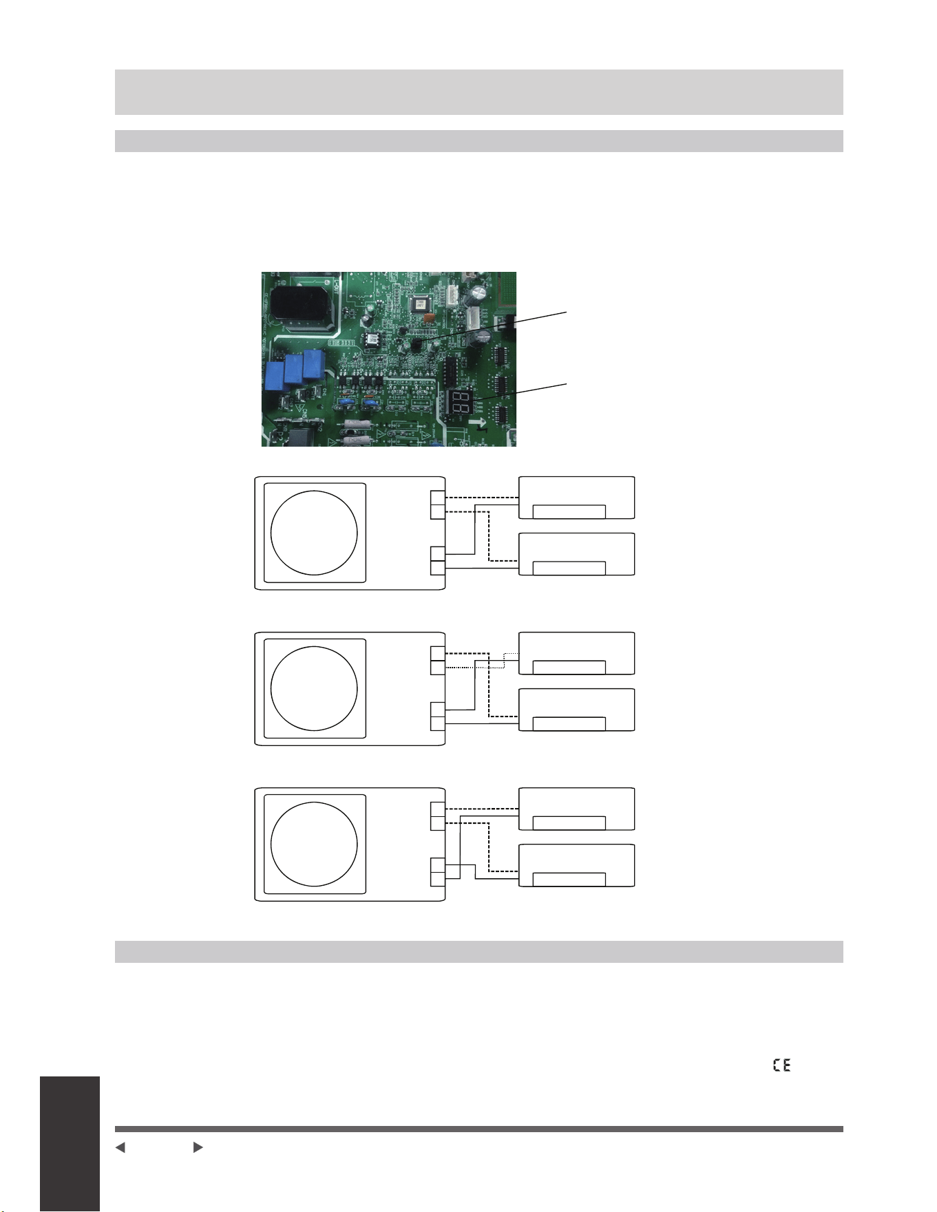
Fonction de
correction
automatique
Fonction GHOD correction automatique de câblage/tuyauterie
Fonction de correction automatique de câblage/tuyauterie
/HVPRGqOHVSOXVUpFHQWVFRPSRUWHQWGpVRUPDLVXQHFRUUHFWLRQDXWRPDWLTXHGHVHUUHXUVGHFkEODJHHWGH
tuyauterie. Appuyez sur l’interrupteur de contrôle sur l’unité extérieure du panneau PCB pendant 5 secondes
MXVTX¶jFHTXHOD/('DI¿FKH©&(ªLQGLTXDQWTXHFHWWHIRQFWLRQHVWDFWLYpH(QYLURQjPLQXWHVDSUqVDYRLU
DSSX\pVXUO¶LQWHUUXSWHXUOH©&(ªGLVSDUDvWFHTXLVLJQL¿HTXHO¶HUUHXUGHFkEODJHWX\DXWHULHHVWFRUULJpHHWTXH
tous les câblages / tuyauteries sont correctement connectés.
B
A
B
A
B
A
B
A
B
A
B
A
$I¿FKDJH/('
Correct
Câblage incorrect
Câblage incorrect
Unité intérieure B
Unité intérieure B
Unité intérieure B
Unité intérieure A
Unité intérieure A
Unité intérieure A
Boîte à
borne
Boîte à
borne
Boîte à
borne
Interrupteur de contrôle
Tuyau de
OLTXLGH
gaz
Unité extérieure
Tuyau de
OLTXLGH
gaz
Unité extérieure
Tuyau de
OLTXLGH
gaz
Unité extérieure
Comment activer cette fonction
9pUL¿H]TXHODWHPSpUDWXUHH[WpULHXUHHVWVXSpULHXUHj&
&HWWHIRQFWLRQQHIRQFWLRQQHSDVORUVTXHODWHPSpUDWXUHH[WpULHXUHQ¶HVWSDVVXSpULHXUHj&
9pUL¿H]TXHOHVYDQQHVG¶DUUrWGXWX\DXGHOLTXLGHHWGHJD]VRQWRXYHUWHV
3. Allumez le disjoncteur et attendez au moins 2 minutes.
$SSX\H]VXUO¶LQWHUUXSWHXUGHFRQWU{OHVXUO¶XQLWpH[WpULHXUHGXSDQQHDX3&%DYHFO¶DI¿FKDJH/('©
ª
Page 42


La conception et les spéci¿cations sont sujettes à changement sans préavis pour
l’amélioration du produit. Veuillez consulter l’agence de vente ou le fabricant pour
plus de détails. Toute mise à jour du manuel sera téléchargée sur le site web du
service, veuillez véri¿er la dernière version.
All specifications subject to change without notice.
©2022 ECR International, Inc.
PN 615000580
[05/01/2022]
2201 Dwyer Avenue, Utica,a, NY 13501
Tel. 800 325-5479
www.ecrinternational.com