SPLIT-TYPE ROOM AIR CONDITIONER
IMPORTANT NOTE:
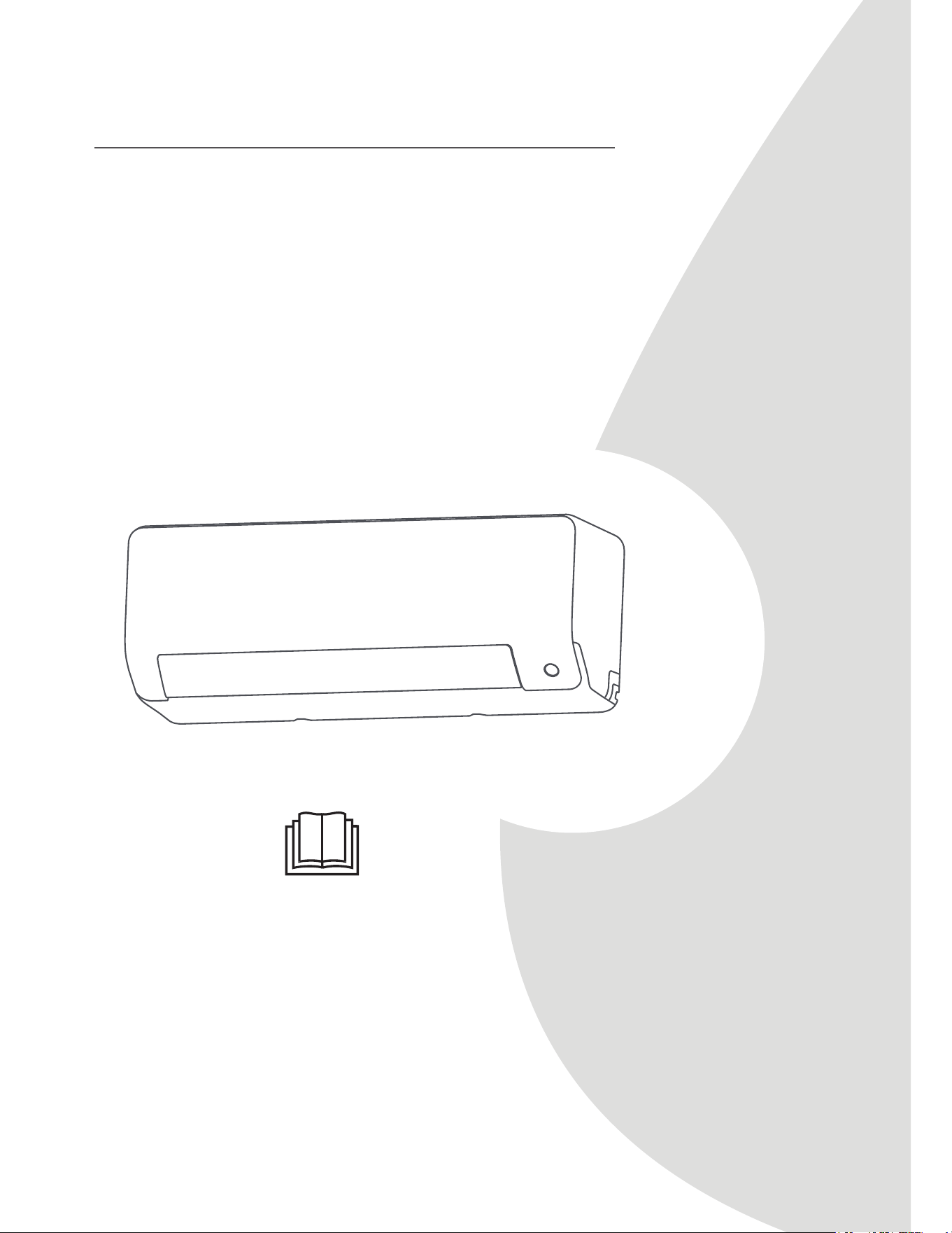
Read this manual and SAFETY MANUAL(if any)
carefully before installing or operating your new
air conditioning unit. Make sure to save this
manual for future reference.
Please check the applicable models, technical
data, F-GAS(if any) and manufacturer information
from the “Owner's Manual - Product Fiche ”
in the packaging of the outdoor unit (European Union
products only) or in the packaging of the indoor unit
(model dependent)
Owner’s Manual &
Installation Manual
MHWAL Series
6-24 kBtu/h

Unit Specifications and Features
...........................................................08
Owner’s Manual
Table of Contents
Safety Precautions
...............................................................................04
Care and Maintenance
......................................................................12
Troubleshooting.................................................................................14
1. Indoor unit display.........................................................................................................................08
2. Operating temperature..................................................................................................................09
3. Other features ..............................................................................................................................10
4. Setting angle of airflow.................................................................................................................11
5. Manual operation (without Remote)..............................................................................................11

Installation Manual
Accessories
...........................................................................................17
Unit Parts
.............................................................................................19
Indoor Unit Installation
.......................................................................20
1. Select installation location..............................................................................................................20
2. Attach mounting plate to wall........................................................................................................20
3. Drill wall hole for connective piping................................................................................................21
4. Prepare refrigerant piping...............................................................................................................22
5. Connect drain hose........................................................................................................................24
6. Connect signal and power cables...................................................................................................25
7. Wrap piping and cables..................................................................................................................26
8. Mount indoor unit.........................................................................................................................27
Outdoor Unit Installation.........................................................................27
1. Select installation location..............................................................................................................27
2. Install drain joint............................................................................................................................28
3. Anchor outdoor unit......................................................................................................................28
4. Connect signal and power cables...................................................................................................30
Refrigerant Piping Connection.........................................................31
A. Note on Pipe Length....................................................................................................................31
B.
Connection Instructions –Refrigerant Piping.................................................................................31
1. Cut pipe.................................................................................................................................31
2. Remove burrs.........................................................................................................................32
3. Flare pipe ends.......................................................................................................................32
4. Connect pipes........................................................................................................................32
Air Evacuation...................................................................................34
1. Evacuation Instructions................................................................................................................34
2. Note on Adding Refrigerant.........................................................................................................35
Electrical and Gas Leak Checks........................................................36
Test Run.............................................................................................37
Packing and unpacking the unit .....................................................38
Installation Summary - Indoor Unit ..................................................18
e
Page 5
f
Safety
Precautions
CAUTION
UÊ
Turn off the air conditioner and disconnect the power if you are not going to use it for a long time.
UÊ
Turn off and unplug the unit during storms.
UÊ
Make sure that water condensation can drain unhindered from the unit.
UÊ Do not
operate the air conditioner with wet hands. This may cause electric shock.
UÊ Do not
use device for any other purpose than its intended use.
UÊ Do not
climb onto or place objects on top of the outdoor unit.
UÊ Do not
allow the air conditioner to operate for long periods of time with doors or windows open,
or if the humidity is very high.
ELECTRICAL WARNINGS
UÊ
Only use the specified power cord. If the power cord is damaged, it must be replaced by the
manufacturer
, its service agent or similarly qualified persons in order to avoid a hazard.
UÊ
Keep power plug clean. Remove any dust or grime that accumulates on or around the plug. Dirty
plugs can cause fire or electric shock.
UÊ
UÊ
UÊ
UÊ
UÊ
UÊ
UÊ
Do not
pull power cord to unplug unit. Hold the plug firmly and pull it from the outlet. Pulling
directly on the cord can damage it, which can lead to fire or electric shock.
Do not
modify the length of the power supply cord or use an extension cord to power the unit.
Do not
share the electrical outlet with other appliances. Improper or insufficient power supply
can cause fire or electrical shock.
If connecting power to fixed wiring, an all-pole disconnection device which has at least 3mm
clearances in all poles, and have a leakage current that may exceed 10mA, the residual current
device(RCD) having a rated residual operating current not exceeding 30mA, and disconnection
must be incorporated in the fixed wiring in accordance with the wiring rules.
For all electrical work, follow all local and national wiring standards, regulations, and the
Installation Manual. Connect cables tightly, and clamp them securely to prevent external forces
from damaging the terminal. Improper electrical connections can overheat and cause fire, and may
also cause shock.
All electrical connections must be made according to the Electrical Connection
Diagram located on the panels of the indoor and outdoor units.
All wiring must be properly arranged to ensure that the control board cover can close properly. If
the control board cover is not closed properly, it can lead to corrosion and cause the connection
points on the terminal to heat up, catch fire, or cause electrical shock.
The product must be properly grounded at the time of installation, or electrical shock may occur.
TAKE NOTE OF FUSE SPECIFICATIONS
The air conditioner’s circuit board (PCB) is designed with a fuse to provide overcurrent protection.
The specifications of the fuse are printed on the circuit board ,such as :
T3.15AL/250VAC, T5AL/250VAC, T3.15A/250VAC, T5A/250VAC, T20A/250VAC, T30A/250VAC,etc.
NOTE: For the units using R32 or R290 refrigerant , only the blast-proof ceramic fuse can be used.
UV-C lamp(Applicable to the unit contains an UV-C lamp only)
This appliance contains a UV-C lamp. Read the maintenance instructions before opening the appliance.
1. Do not operate UV-C lamps outside of the appliance.
2. Appliances that are obviously damaged must not be operated.
3. Unintended use of the appliance or damage to the housing may result in the escape of dangerous UV-C
radiation. UV-C radiation may, even in small doses, cause harm to the eyes and skin.

e
Page 6
f
Safety
Precautions
WARNINGS FOR PRODUCT INSTALLATION
1.
Installation must be performed by an authorized dealer or specialist. Defective installation can
cause water leakage, electrical shock, or fire.
2.
Installation must be performed according to the installation instructions. Improper installation
can cause water leakage, electrical shock, or fire.
(In North America,installation must be performed in accordance with the requirement of NEC
and CEC by authorized personnel only.)
3.
Contact an authorized service technician for repair or maintenance of this unit. This appliance
shall be installed in accordance with national wiring regulations.
4.
Only use the included accessories, parts, and specified parts for installation. Using non-standard
parts can cause water leakage, electrical shock, fire, and can cause the unit to fail.
5.
6.
Install the unit in a firm location that can support the unit’s weight. If the chosen location cannot
support the unit’s weight, or the installation is not done properly, the unit may drop and cause
serious injury and damage.
7.
8.
9.
10.
11.
Do not turn on the power until all work has been completed.
When moving or relocating the air conditioner, consult experienced service technicians for
disconnection and reinstallation of the unit.
How to install the appliance to its support, please read the information for details in "indoor unit
installation" and "outdoor unit installation" sections .
For units that have an auxiliary electric heater, do not install the unit within 1 meter (3 feet) of
any combustible materials.
Do not
install the unit in a location that may be exposed to combustible gas leaks. If
combustible
gas accumulates around the unit, it may cause fire.
Install drainage piping according to the instructions in this manual. Improper drainage may
cause water damage to your home and property.
Note about Fluorinated Gasses(Not applicable to the unit using R290 Refrigerant)
1.
This air-conditioning unit contains fluorinated greenhouse gasses. For specific information on the
type of gas and the amount, please refer to the relevant label on the unit itself or
the
“Owner's Manual - Product Fiche ” in the packaging of the outdoor unit.
(European
Union products only)
.
2.
Installation, service, maintenance and repair of this unit must be performed by a certified
technician.
3.
Product uninstallation and recycling must be performed by a certified technician.
4.
For equipment that contains fluorinated greenhouse gases in quantities of 5 tonnes of CO
2
equivalent or more, but of less than 50 tonnes of CO
2
equivalent, If the system has a leak-
detection system installed, it must be checked for leaks at least every 24 months.
5.
When the unit is checked for leaks, proper record-keeping of all checks is strongly recommended.
4.
Before opening doors and access panels bearing the ULTRAVIOLET RADIATION hazard symbol
for the conducting USER MAINTENANCE, it is recommended to disconnect the power.
5. The UV-C lamp can not be cleaned, repaired and replaced.
6. UV-C BARRIERS bearing the ULTRAVIOLET RADIATION hazard symbol should not be removed.
WARNING
This appliance contains an UV emitter. Do not stare at the light source.
e
Page 7
f
Safety
Precautions
European Disposal Guidelines
This appliance contains refrigerant and other potentially hazardous materials. When disposing of
this appliance, the law requires special collection and treatment. Do not dispose of this product as
household waste or unsorted municipal waste.
When disposing of this appliance, you have the following options:
U Dispose
of
the
appliance
at
designated
municipal
electronic
waste
collection
facility.
U When buying a new appliance, the retailer will take back the old appliance free of charge.
U The manufacturer will take back the old appliance free of charge.
U Sell the appliance to certified scrap metal dealers.
Special notice
Disposing of this appliance in the forest or other natural surroundings endangers your health and is
bad for the environment. Hazardous substances may leak into the ground water and enter the food
chain.
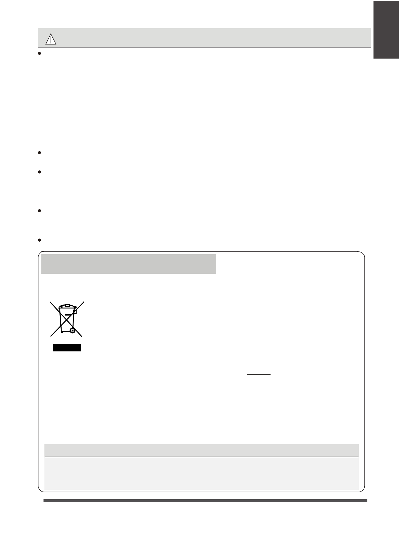
Correct Disposal of This Product
(Waste Electrical & Electronic Equipment)
This marking shown on the product or its literature, indicates that waste electrical and
eletrical equipment should not be mixed with general household waste.
WARNING for Using R32/R290 Refrigerant
2
2
2
2
2
When flammable refrigerant are employed, appliance shall be stored in a well -ventilated area
where the room size corresponds to the room area as specifiec for operation.
For R32 frigerant models:
Appliance shall be installed, operated and stored in a room with a floor area larger than 4m .
For R290 refrigerant models, appliance shall be installed, operated and stored in a room with
a floor area larger than:
<=9000Btu/h units: 13m
>9000Btu/h and <=12000Btu/h units: 17m
>12000Btu/h and <=18000Btu/h units: 26m
>18000Btu/h and <=24000Btu/h units: 35m
Reusable mechanical connectors and flared joints are not allowed indoors.
(EN Standard Requirements).
Mechanical connectors used indoors shall have a rate of not more than 3g/year at 25%
of the maximum allowable pressure. When mechanical connectors are reused indoors,
sealing parts shall be renewed. When flared joints are reused indoors, the flare part
shall be re-fabricated. (UL Standard Requirements)
When mechanical connectors are reused indoors, sealing parts shall be renewed. When
flared joints are reused indoors, the flare part shall be re-fabricated.
(IEC Standard Requirements)
Mechanical connectors used indoors shall comply with ISO 14903.
e
Page 8
f
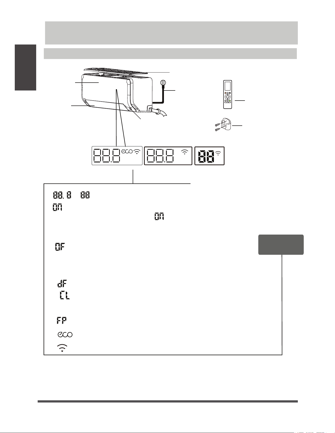
Illustrations in this manual are for explanatory purposes. The actual shape of your indoor unit
may be slightly different. The actual shape shall prevail.
NOTE:ÑDifferent models have different front panel and display window. Not all the indicators
describing below are available for the air conditioner you purchased. Please check the indoor display
window of the unit you purchased.
Power Cable
(Some Units)
Remote Control
Remote Control
Holder (Some Units)
Louver
Front Panel
Air Filter
(pull up)
Display window
(A)
(B)
(C)
ECO intelligent eye
(some units)
Display Code
Meanings
Unit Specifications and Features
Indoor unit display
Unit
Specifications
and Features
“ ” for 3 seconds when:
t5*.&30''JTTFU
iwXIFOEFGSPTUJOHGPSDPPMJOHIFBUJOHVOJUT
iwXIFO"DUJWF$MFBOGFBUVSFJTUVSOFEPO'PS*OWFSUFSTQMJUUZQF
XIFOUIF4FMGDMFBOGFBUVSFJTUVSOFEPO'PSmYFETQFFEUZQF
iwXIFO&$0GFBUVSFJTBDUJWBUFETPNFVOJUT
iwXIFOXJSFMFTTDPOUSPMGFBUVSFJTBDUJWBUFETPNFVOJUT
iwiw%JTQMBZTUFNQFSBUVSFPQFSBUJPOGFBUVSFBOE&SSPSDPEFT
“ ” when 8°C(46°F) IFBUJOHNPEFJTUVSOFEPOTPNFVOJUT
Humidity
Boost
“ ” for 3 seconds when:
t5*.&30/JTTFU
JGUIFVOJUJT0''SFNBJOTPOXIFO5*.&30/JTTFU
t'3&4)67$MBNQ48*/(563#0&$0#3&&;&"8":
&$0*/5&--*(&/5&:&PS4*-&/$&GFBUVSFJTUVSOFEPO
t'3&4)67$MBNQ48*/(563#0&$0#3&&;&"8":
&$0*/5&--*(&/5&:&PS4*-&/$&GFBUVSFJTUVSOFEPGG
“ ”
-30°C - 24°C
(-22°F - 75°F)
-30°C - 50°C
(-22°F - 122°F)
e
Page 10
f
Unit
Specifications
and Features
Other Features
UÊ Auto-Restart(some units)
If the unit loses power, it will automatically
restart with the prior settings once power has
been restored.
UÊ Anti-mildew (some units)
When turning off the unit from COOL, AUTO
(COOL), or DRY modes, the air conditioner will
continue operate at very low power to dry up
condensed water and prevent mildew growth.
UÊ Wireless Control(some units)
Wireless control allows you to control your air
conditioner using your mobile phone and a
wireless connection.
UÊ Louver Angle Memory(some units)
When turning on your unit, the louver will
automatically resume its former angle.
UÊ Refrigerant Leakage Detection(some units)
UÊ ECO Intelligent eye(some units)
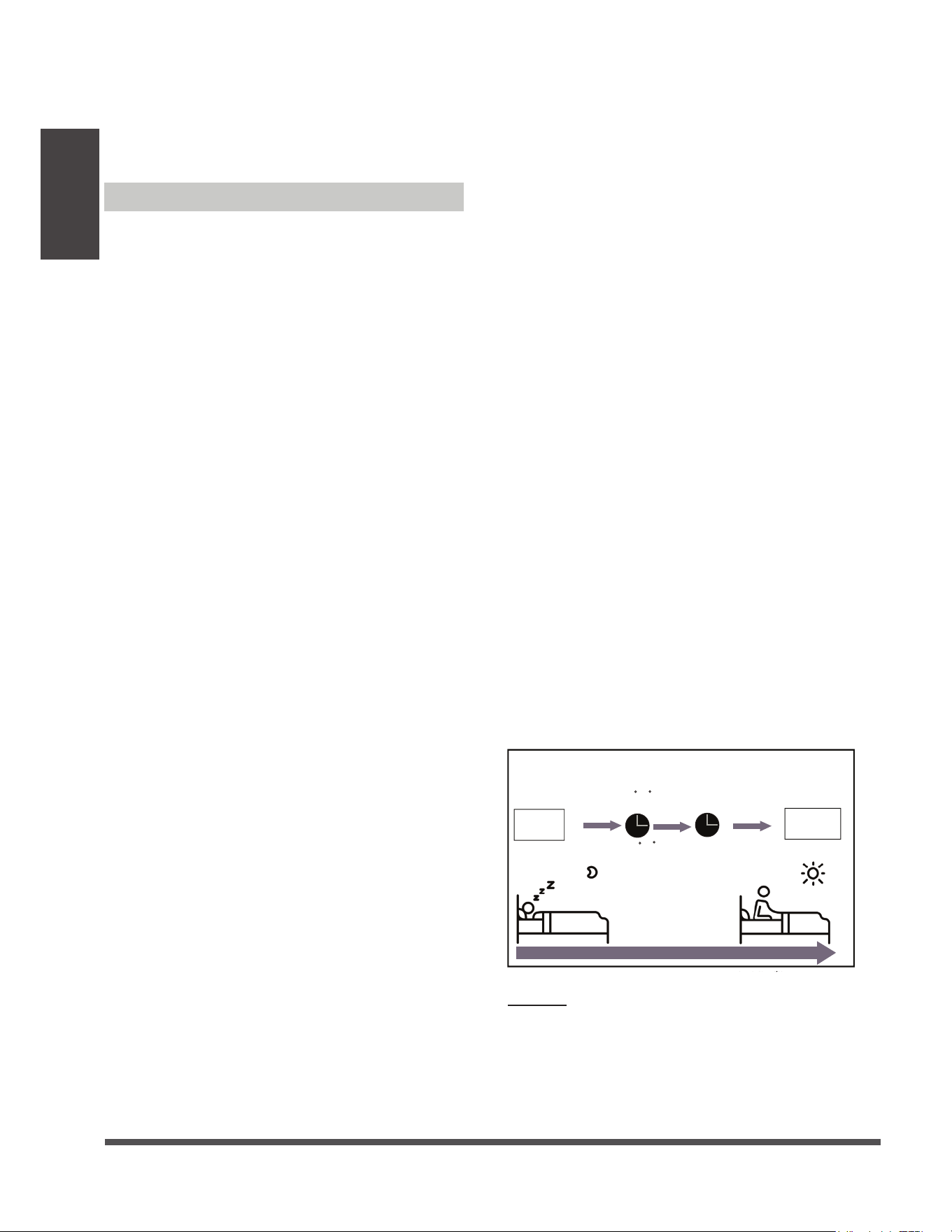
The SLEEP function is used to decrease
energy use while you sleep (and don’t
need the same temperature settings to
stay comfortable). This function can only
be activated via remote control. And the
Sleep function is not available in FAN or
DRY mode.
When in COOL mode, the unit will increase
the temperature by 1°C (2°F) after 1 hour,
and will increase an additional 1°C (2°F) after
another hour.
When in HEAT mode, the unit will decrease
the temperature by 1°C (2°F) after 1 hour,
and will decrease an additional 1°C (2°F)
after another hour.
Sleep Operation
UÊ
For the USB device access, replacement,
maintenance operations must be carried
out by professional staff.
Set
temperature
1hr
1hr
Keep
running
SLEEP Operation
Saving energy during sleep
Heat mode( -1 C/2 F) per hour
for the first two hours
Cool mode(+1 C/2 F) per hour
for the first two hours
A guide on using the infrared remote is not
included in this literature package.
Not all
the functions are available for the air
conditioner, please check the indoor display
and remote control of the unit you purchased.
The sleep feature will stop after 8 hours and
the system will keep running with final situation.
For multi-split air condtioners, the following
functions are not available:
Active clean function, Silence feature, Breeze
away function, Refrigerant leakage detection
function and Eco feature.
NOTE:
UÊ Active Clean function(some units)
-- The Active Clean Technology washes away
dust, mold, and grease that may cause odors
when it adheres to the heat exchanger by
automatically freezing and then rapidly thawing
the frost. A “pi-pi” sound will be heard.
The Active clean operation is used to produce
more condensed water to improve the cleaning
effect, and the cold air will blow out. After
cleaning, the internal wind wheel then keeps
operating with hot air to blow-dry the evaporator,
thus preventing the growth of mold and keeping
the inside clean.
-- When this function is turned on, the indoor
unit display window appears “CL ” , after 20
to 45 minutes, the unit will turn off automatically
and cancel Active Clean function.
UÊ Breeze Away (some units)
This feature avoids direct air flow blowing on
the body and make you feel indulging in
silky coolness.
The indoor unit will automatically display “EL0C”
when it detects refrigerant leakage.
The system is controlled intelligently under
Intelligent eye mode. It can detect the people’s
activities in the room. In cooling mode, when you
are away for 30 minutes, the unit will automatically
lower the frequency to save energy(for Inverter
models only). And the unit will automatically start
and resume operation if sensing human activity
again.
e
Page 11
f
Unit
Specifications
and Features
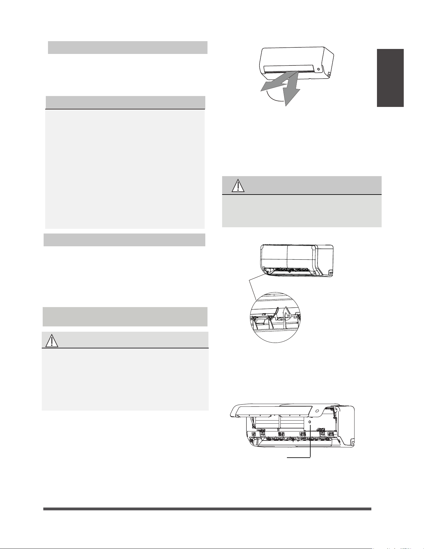
Setting vertical angle of air flow
While the unit is on, use the SWING
button on remote control to set the direction
(vertical angle) of airflow. Please refer to the
Remote Control Manual for details.
The horizontal angle of the airflow must be set
manually. Grip the deflector rod (See Fig.B)
and manually adjust it to your preferred direction.
For some units, the horizontal angle of the airflow
can be set by remote control. please refer to the
Remote Control Manual.
NOTE ON LOUVER ANGLES
When using COOL or DRY mode, do not set
louver at too vertical an angle for long periods
of time. This can cause water to condense on
the louver blade, which will drop on your floor
or furnishings.
When using COOL or HEAT mode, setting the
louver at too vertical an angle can reduce the
performance of the unit due to restricted air flow.
NOTE: According to the relative standards
requirement,
please sets the vertical air flow
louver to its maximum angle
under heating
capacity test.
CAUTION
Do not put your fingers in or near the blower
and suction side of the unit. The high-speed
fan inside the unit may cause injury.
Fig. A
Fig. B
Fig. C
Setting Angle of Air Flow
Setting horizontal angle of air flow
UÊ
To operate your unit manually:
1.
Locate the
MANUAL CONTROL button on
the right-hand side panel of the unit.
2.
Press the MANUAL CONTROL button one
time to activate FORCED AUTO mode.
3.
Press the MANUAL CONTROL button again
to activate FORCED COOLING mode.
4.
Press the MANUAL CONTROL button a third
time to turn the unit off.
CAUTION
The manual button is intended for testing purposes
and emergency operation only. Please do not use this
function unless the remote control is lost and it is
absolutely necessary. To restore regular operation,
use the remote control to activate the unit. Unit must
be turned off before manual operation.
Manual Operation(without remote)
NOTE: Do not move louver by hand. This will
cause the louver to become out of sync. If this
occurs, turn off the unit and unplug it for a few
seconds, then restart the unit. This will reset the
louver.
Range
Deflector
rod
.BOVBMDPOUSPM
CVUUPO
AUTO COOL
e
Page 12
f
Care and
Maintenance
Cleaning Your Indoor Unit
BEFORE CLEANING OR
MAINTENANCE
ALWAYS TURN OFF YOUR AIR CONDITIONER
SYSTEM AND DISCONNECT ITS POWER
SUPPLY BEFORE CLEANING OR MAINTENANCE.
CAUTION
Only use a soft, dry cloth to wipe the unit clean.
If the unit is especially dirty, you can use a cloth
soaked in warm water to wipe it clean.
UÊ
Do not
use chemicals or chemically treated
cloths to clean the unit
UÊ
Do not use benzene, paint thinner,
polishing powder or other solvents to clean
the unit. They can cause the plastic surface
to crack or deform.
UÊ
Do not use water hotter than 40°C (104°F)
to clean the front panel. This can cause the
panel to deform or become discolored.
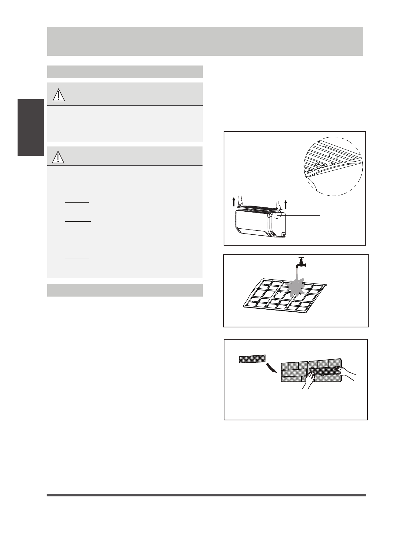
Cleaning Your Air Filter
A clogged air filter can reduce the cooling efficiency
of your unit, can also make the air flow irregular
and too much noisy, so please clean the air filter
as often as necessary. Once the abnormal noise
of air flow is heard, please clean the air filter
immediately.
1.
The air filter is on the top of the air conditioner.
2.
Hold both side of the top filter in the place
marked with “PULL”, then pull it upwards.
3.
If your filter has small air freshening filters,
unclip them from the larger filter. Clean these
air freshening filters with a hand-held vacuum.
4. Clean the large air filter with warm, soapy
water. Be sure to use a mild detergent.
5.
Rinse the filter with fresh water, then shake
off excess water.
6.
Dry it in a cool, dry place, and refrain from
exposing it to direct sunlight.
7.
When dry, re-clip the air freshening filter to
the larger filter, then install it back on the
indoor unit.
Hold both side of the top
filter in the place marked
with “PULL”, pull it upwards
Care and Maintenance
PULL
Remove air freshening filter from back of
larger filter(some units), clean with a hand-
held vacuum.
e
Page 13
f
Air Filter Reminders (Optional)
Air Filter Cleaning Reminder
After 240 hours of use, the display window on
the indoor unit will flash “CL.” This is a reminder
to clean your filter. After 15 seconds, the unit will
revert to its previous display.
To reset the reminder, press the LED button
on your remote control 4 times, or press the
MANUAL CONTROL button 3 times. If you don’t
reset the reminder, the “CL” indicator will flash
again when you restart the unit.
Air Filter Replacement Reminder
After 2,880 hours of use, the display window on
the indoor unit will flash “nF.” This is a reminder
to replace your filter. After 15 seconds, the unit
will revert to its previous display.
To reset the reminder, press the LED button
on your remote control 4 times, or press the
MANUAL CONTROL button 3 times. If you don’t
reset the reminder, the “nF” indicator will flash
again when you restart the unit.
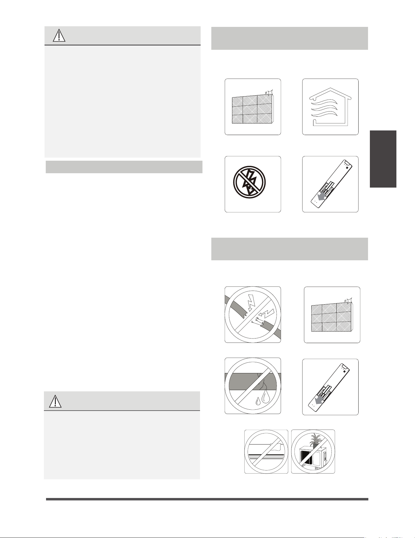
Maintenance –
Long Periods of Non-Use
If you plan not to use your air conditioner for an
extended period of time, do the following:
Clean all filters
Turn on FAN function until
unit dries out completely
Turn off the unit and
disconnect the power
Remove batteries
from remote control
Maintenance –
Pre-Season Inspection
After long periods of non-use, or before periods
of frequent use, do the following:
Check for damaged wires Clean all filters
Check for leaks Replace batteries
Make sure nothing is blocking all air inlets and outlets
Care and
Maintenance
CAUTION
UÊ
Before changing the filter or cleaning,
turn off the unit and disconnect its power
supply.
UÊ
When removing filter, do not touch metal
parts in the unit. The sharp metal edges can
cut you.
UÊ
Do not use water to clean the inside of the
indoor unit. This can destroy insulation and
cause electrical shock.
UÊ
Do not expose filter to direct sunlight when
drying. This can shrink the filter.
CAUTION
UÊ
Any maintenance and cleaning of outdoor
unit should be performed by an authorized
dealer or a licensed service provider.
UÊ
Any unit repairs should be performed
by an authorized dealer or a licensed
service provider.

e
Page 14
f
Common Issues
The following problems are not a malfunction and in most situations will not require repairs.
Issue Possible Causes
Unit does not turn
on when pressing
ON/OFF button
The Unit has a 3-minute protection feature that prevents the unit from
overloading. The unit cannot be restarted within three minutes of being
turned off.
The unit may change its setting to prevent frost from forming on the unit.
Once the temperature increases, the unit will start operating in the
previously selected mode again.
The set temperature has been reached, at which point the unit turns off the
compressor. The unit will continue operating when the temperature
fluctuates again.
The indoor unit
emits white mist
In humid regions, a large temperature difference between the room’s air
and the conditioned air can cause white mist.
Both the indoor and
outdoor units emit
white mist
When the unit restarts in HEAT mode after defrosting, white mist may be
emitted due to moisture generated from the defrosting process.
Troubleshooting
The unit changes from
COOL/HEAT mode to
FAN mode
The indoor unit makes
noises
A rushing air sound may occur when the louver resets its position.
A squeaking sound may occur after running the unit in HEAT mode due to
expansion and contraction of the unit’s plastic parts.
Both the indoor unit
and outdoor unit make
noises
Low hissing sound during operation: This is normal and is caused by refrigerant
gas flowing through both indoor and outdoor units.
Low hissing sound when the system starts, has just stopped running, or is
defrosting: This noise is normal and is caused by the refrigerant gas stopping or
changing direction.
Squeaking sound: Normal expansion and contraction of plastic and metal parts
caused by temperature changes during operation can cause squeaking noises.
SAFETY PRECAUTIONS
If ANY of the following conditions occurs, turn off your unit immediately!
UÊ The power cord is damaged or abnormally warm
UÊ You smell a burning odor
UÊ The unit emits loud or abnormal sounds
UÊ A power fuse blows or the circuit breaker frequently trips
UÊ Water or other objects fall into or out of the unit
DO NOT ATTEMPT TO FIX THESE YOURSELF! CONTACT AN AUTHORIZED
SERVICE PROVIDER IMMEDIATELY!
Troubleshooting

e
Page 15
f
Issue Possible Causes
The outdoor unit
makes noises
The unit will make different sounds based on its current operating mode.
Dust is emitted from
either the indoor or
outdoor unit
The unit may accumulate dust during extended periods of non-use, which will be
emitted when the unit is turned on. This can be mitigated by covering the unit during
long periods of inactivity.
The unit emits a
bad odor
The unit may absorb odors from the environment (such as furniture, cooking,
cigarettes, etc.) which will be emitted during operations.
The unit’s filters have become moldy and should be cleaned.
The fan of the outdoor
unit does not operate
During operation, the fan speed is controlled to optimize product operation.
Operation is erratic,
unpredictable, or
unit is unresponsive
Interference from cell phone towers and remote boosters may cause the unit to
malfunction.
In this case, try the following:
UÊ
Disconnect the power, then reconnect.
UÊ
Press ON/OFF button on remote control to restart operation.
NOTE:
If problem persists, contact a local dealer or your nearest customer service center. Provide
them with a detailed description of the unit malfunction as well as your model number.
Troubleshooting
Troubleshooting
When troubles occur, please check the following points before contacting a repair company.
Problem Possible Causes Solution
Poor Cooling
Performance
Temperature setting may be higher
than ambient room temperature
Lower the temperature setting
The heat exchanger on the indoor
or outdoor unit is dirty
Clean the affected heat exchanger
The air filter is dirty
Remove the filter and clean it according to
instructions
The air inlet or outlet of either
unit is blocked
Turn the unit off, remove the obstruction
and turn it back on
Doors and windows are open
Make sure that all doors and windows are
closed while operating the unit
Excessive heat is generated
by sunlight
Close windows and curtains during periods
of high heat or bright sunshine
Too many sources of heat in the
room (people, computers,
electronics, etc.)
Reduce amount of heat sources
Low refrigerant due to leak
or long-term use
Check for leaks, re-seal if necessary and
top off refrigerant
SILENCE function is activated
(optional function)
SILENCE function can lower product
performance by reducing operating
frequency. Turn off SILENCE function.

e
Page 16
f
Troubleshooting
Problem Possible Causes Solution
The unit is not
working
Power failure
Wait for the power to be restored
The power is turned off Turn on the power
The fuse is burned out
Replace the fuse
Remote control batteries are dead
Replace batteries
The Unit’s 3-minute protection
has been activated
Wait three minutes after restarting
the unit
Timer is activated
Turn timer off
The unit starts and
stops frequently
There’s too much or too little
refrigerant in the system
Check for leaks and recharge the
system with refrigerant.
Incompressible gas or moisture
has entered the system.
Evacuate and recharge the system
with refrigerant
The compressor is broken Replace the compressor
The voltage is too high or
too low
Install a manostat to regulate the
voltage
Poor heating
performance
The outdoor temperature is
extremely low
Use auxiliary heating device
Cold air is entering through
doors and windows
Make sure that all doors and
windows are closed during use
Low refrigerant due to leak or
long-term use
Check for leaks, re-seal if necessary
and top off refrigerant
Indicator lamps
continue flashing
The unit may stop operation or continue to run safely. If the indicator
lamps continue to flash or error codes appear, wait for about 10
minutes. The problem may resolve itself.
If not, disconnect the power, then connect it again. Turn the unit on.
If the problem persists, disconnect the power and contact your nearest
customer service center.
Error code appears and
begins with the letters
as the following in the
window display of
indoor unit:
E(x), P(x), F(x)
EH(xx), EL(xx), EC(xx)
PH(xx), PL(xx), PC(xx)
U
UÊ
UÊ
NOTE:
If your problem persists after performing the checks and diagnostics above,
turn off your unit immediately and contact an authorized service center.
e
Page 17
f
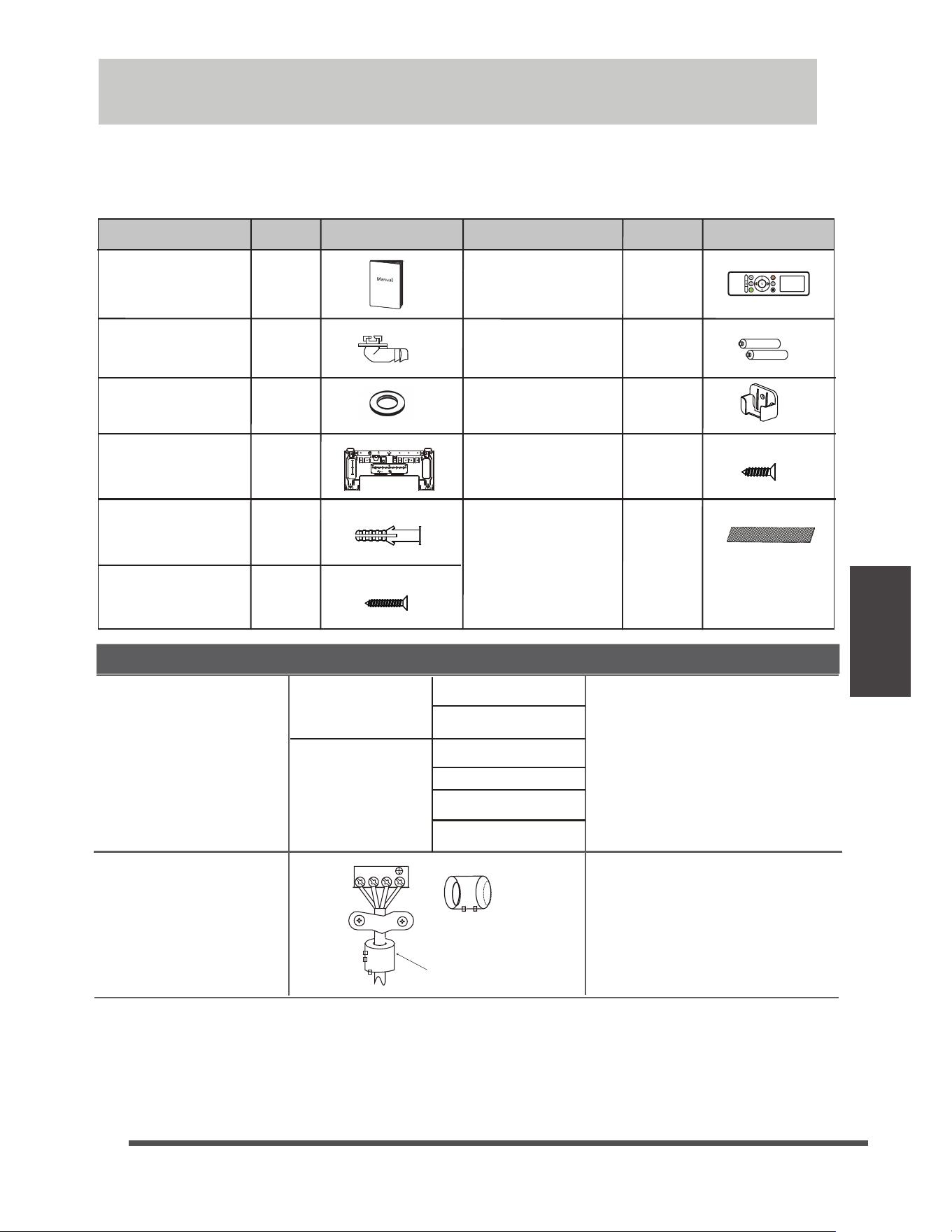
Accessories
The air conditioning system comes with the following accessories. Use all of the installation parts
and accessories to install the air conditioner. Improper installation may result in water leakage,
electrical shock and fire, or cause the equipment to fail. The items are not included
with the air conditioner must be purchased separately.
Magnetic ring and belt
Varies by model
1 2 3
(if supplied ,please refer to
the wiring diagram to install
it on the connective cable. )
Pass the belt through
the hole of the Magnetic
ring to fix it on the cable
Name
Shape Quantity(PC)
(Need to be installed on
the back of main air filter
by the authorized
technician while installing
the machine)
Mounting plate
fixing screw
Remote controller
Fixing screw for
remote controller
holder(optional)
Remote controller
holder(optional)
Drain joint
(for cooling &
heating models)
Seal
(for cooling &
heating models)
Mounting plate
Manual
Parts you must purchase
separately. Consult the dealer
about the proper pipe size of
the unit you purchased.
Connecting pipe
assembly
Liquid side
Gas side
6.35(1/4 i n)
9.52(3/8in)
9.52(3/8in)
12.7(1/2in)
16(5/8in)
19( 3/4in)
Accessories
2-3
1
1
1
Anchor
1
2
1
2
Battery
Small Filter
1~2
(depending
on models)
5~8
(depending
on models)
5~8
(depending
on models)
Name of Accessories Name of AccessoriesQ’ty(pc)
Shape Q’ty(pc)
Shape
Humidity
Boost
FROM EDGE TO HOLE CENTER:50mm
FROM EDGE TO HOLE CENTER:100mm
150
100
100
100
50
50
50
2
2
2
4
4
4
6
RECOMMAND
LIQUID
GAS
BUBBLE
LEVEL
mm
inch
mm
inch
e
Page 18
f
Installation
Overview
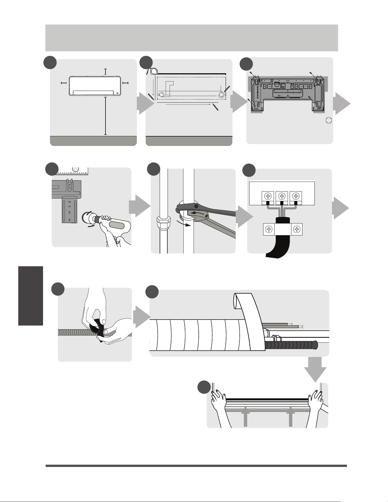
Installation Summary - Indoor Unit
Select Installation Location
Attach Mounting Plate
Determine Wall Hole Position
1 2
3
Drill Wall Hole
4
DN
JO
NJO
DN
JO
Mount Indoor Unit
STEP
8
Wrap Piping and Cable
(not applicable for some locations in North America )
Connect Piping
Prepare Drain Hose
Connect Wiring
(not applicable for some
locations in North America )
4 5
6
7
8
9
%JTUBODFGSPNDFJMJOHJTEFUFSNJOEFE
CZUIFJOTUBMMBUJPONFUIPE
FROM EDGE TO HOLE CENTER:50mm
FROM EDGE TO HOLE CENTER:100mm
150
100
100
100
50
50
50
2
2
2
4
4
4
6
RECOMMAND
LIQUID
GAS
BUBBLE
LEVEL
mm
inch
mm
inch
e
Page 19
f
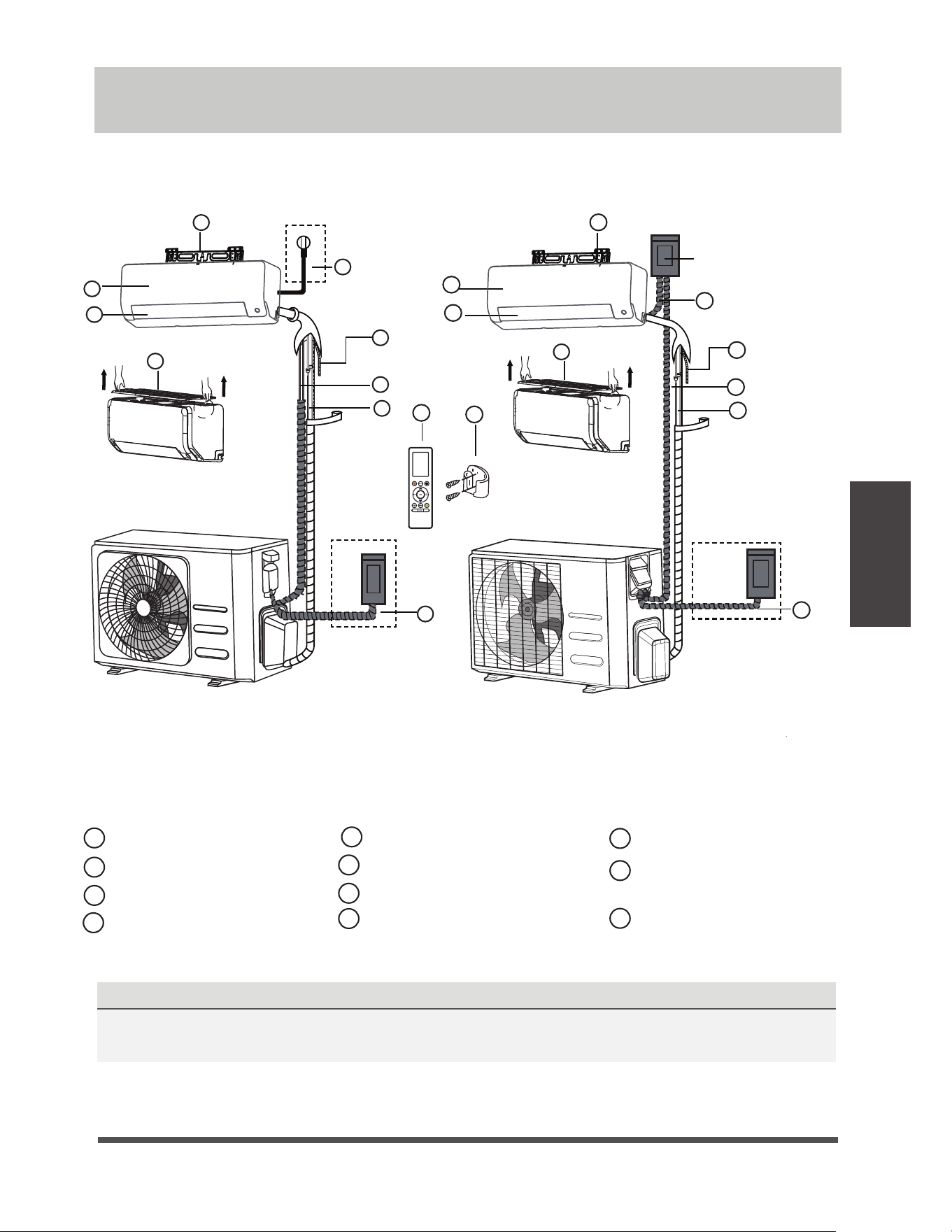
NOTE ON ILLUSTRATIONS
Illustrations in this manual are for explanatory purposes. The actual shape of your indoor
unit may be slightly different. The actual shape shall prevail.
NOTE: The installation must be performed in accordance with the requirement of local and
national standards. The installation may be slightly different in different areas.
Wall Mounting Plate
Power Cable (Some Units)
Refrigerant Piping
Signal Cable
Remote Controller
Drainage Pipe
Louver
Remote Controller Holder
(Some Units)
Air filter(pull it out)
Front Panel
Outdoor Unit Power Cable
(Some Units)
1
2
3
4
5
6
7
8
9
10
11
(1)(2)
1
2
3
4
6
7
8
9
10
11
"JSCSFBLTXJUDI
3
1
2
4
6
7
8
11
5
Unit Parts
Unit Parts
5
Humidity
Boost
e
Page 20
f
Indoor Unit
Installation
Installation Instructions – Indoor unit
PRIOR TO INSTALLATION
Before installing the indoor unit, refer to the
label on the product box to make sure that the
model number of the indoor unit matches the
model number of the outdoor unit.
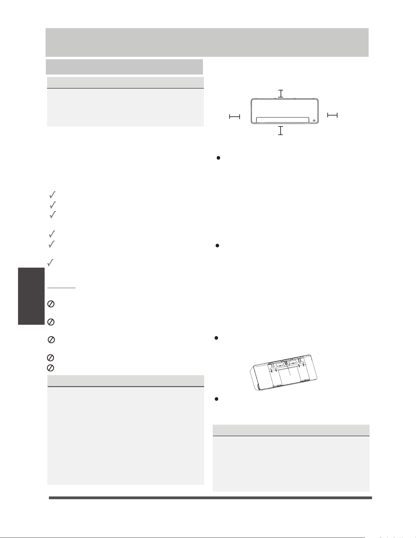
Step 1: Select installation location
Before installing the indoor unit, you must
choose an appropriate location. The following
are standards that will help you choose an
appropriate location for the unit.
Proper installation locations meet the
following standards:
Good air circulation
If no need the back holder to prop up
the unit:
Finishing the pipe and cable connections
before mount the indoor unit on the wall.
If the instllation height is limited, 5cm from
the ceiling is allowable, but this can lower
product performance. To ensure enough
space to install and remove the top air filter,
keep at least 10cm or more from the ceiling.
Need the back holder to prop up the unit:
If connecting pipe and cable with front panel
open, the minimum distance from ceiling is
22cm or more, if connecting pipe and cable
without front panel(remove it) , the minimum
distance from ceiling is 11cm or more.
Convenient drainage
Noise from the unit will not disturb other
people
Firm and solid—the location will not vibrate
Strong enough to support the weight of the
unit
A location at least one meter from all other
electrical devices (e.g., TV, radio, computer)
DO NOT
install unit in the following
locations:
Near any source of heat, steam, or
combustible gas
Near flammable items such as curtains or
clothing
Near any obstacle that might block air
circulation
Near the doorway
In a location subject to direct sunlight
NOTE ABOUT WALL HOLE:
If there is no fixed refrigerant piping:
While choosing a location, be aware that you
should leave ample room for a wall hole (see
Drill wall hole for connective piping step)
for the signal cable and refrigerant piping
that connect the indoor and outdoor units.
The default position for all piping is the right
side of the indoor unit (while facing the unit).
However, the unit can accommodate piping to
both the left and right.
Refer to the following diagram to ensure
proper distance from walls and ceiling:
NOTE:
Step 2: Attach mounting plate to wall
The mounting plate is the device on which you
will mount the indoor unit.
Remove the screw that attaches the mounting
plate to the back of the indoor unit.
Secure the mounting plate to the wall with
the screws provided. Make sure that mounting
plate is flat against the wall.
DNJO
PSNPSF
NJOPSNPSF
DNJO
PSNPSF
%JTUBODFGSPNDFJMJOHJTEFUFSNJOEFE
CZUIFJOTUBMMBUJPONFUIPE
NOTE FOR CONCRETE OR BRICK WALLS:
If the wall is made of brick, concrete, or similar
material, drill 5mm-diameter (0.2in-diameter)
holes in the wall and insert the sleeve anchors
provided. Then secure the mounting plate to
the wall by tightening the screws directly into
the clip anchors.
Screw
Indoor Unit Installation
e
Page 21
f
Indoor Unit
Installation
.PEFM#
Model C
Model A
*OEPPSVOJUPVUMJOF
Unit: mm(inch)
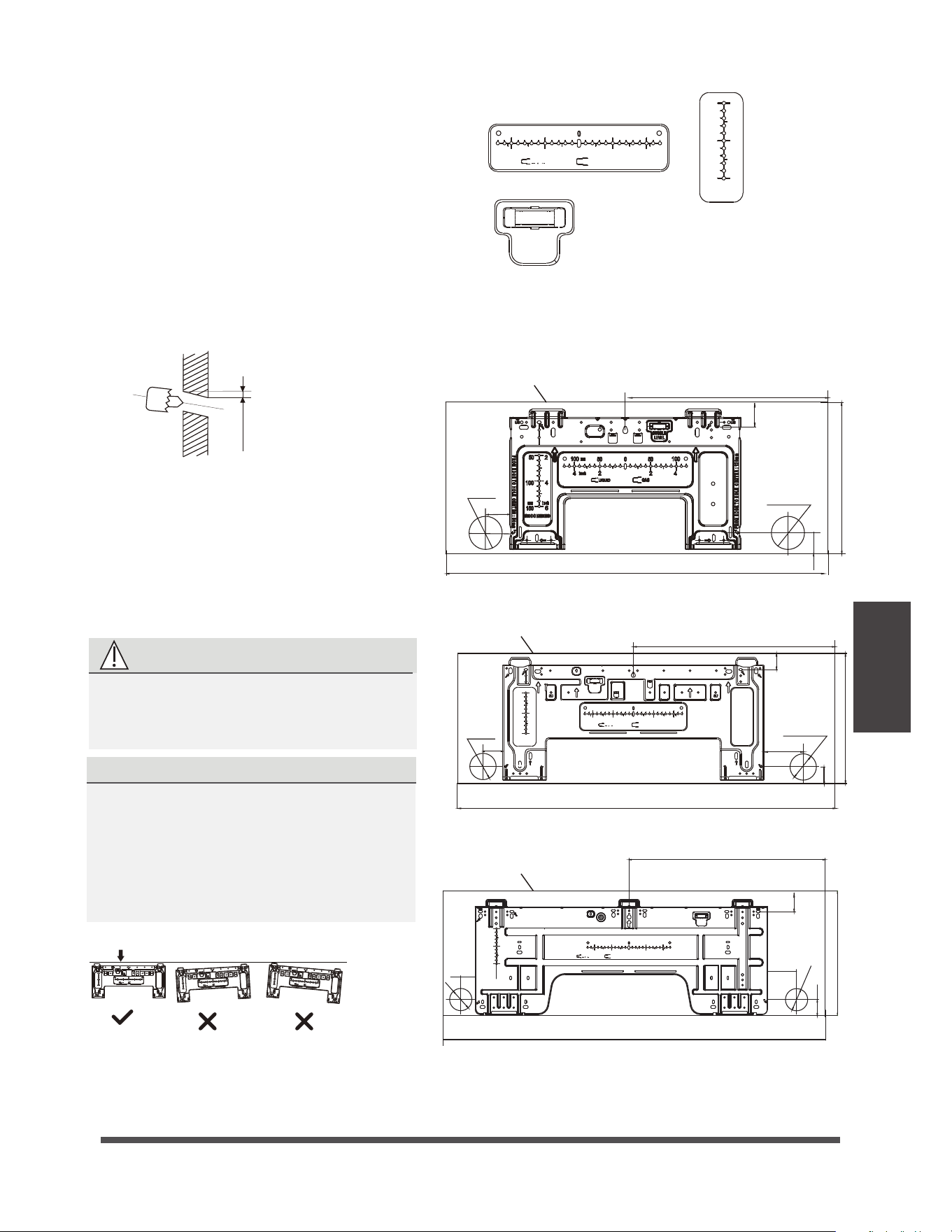
Step 3: Drill wall hole for connective piping
1.
Determine the location of the wall hole based
CAUTION: The Bubble level on the mounting
plate can’t be removed. If it is broken, make
sure to clean up the leaking liquid.
Vertical direction
ruler
Horizontal direction ruler
on the position of the mounting plate. Refer
to Mounting Plate Dimensions.
8BMM
*OEPPS 0VUEPPS
N
N
JO
MOUNTING PLATE DIMENSIONS
Different models have different mounting plates.
For the convenience of installation, there are
bubble level, carved dimensions on the
mounting plate. Please install the plate and drill
wall hole according to the information of the
mounting plate. See the figures below.
$PSSFDUPSJFOUBUJPOPG.PVOUJOH1MBUF
2.
Using a 65mm (2.5in) or 90mm(3.54in)
(depending on models )core drill, drill a
hole in the wall. Make sure that the hole
is drilled at
a slight downward angle, so
that the outdoor end of the hole is lower
than the indoor end by about 5mm to
7mm (0.2-0.275in). This will ensure proper
water drainage.
3.
Place the protective wall cuff in the hole.
This protects the edges of the hole and
will help seal it when you finish the
installation process.
CAUTION
When drilling the wall hole, make sure
to
avoid wires, plumbing, and other
sensitive components.
NOTE: When the gas side connective pipe is
16mm(5/8in) or more, the wall hole should
be 90mm(3.54in).
FROM EDGE TO HOLE CENTER:50mm
FROM EDGE TO HOLE CENTER:50mm
FROM EDGE TO HOLE CENTER:95mm
FROM EDGE TO HOLE CENTER:70mm
150
100
100
965(38)
795(31)
50(1.9)
95(3.7)
120(4.7)
570.7(22.5)
70(2.8)
1140(44.8)
50(1.9)
pipe hole
65(2.5)
pipe hole
65(2.5)
pipe hole
65(2.5)
pipe hole
65(2.5)
pipe hole
65(2.5)
50(1.9)
pipe hole
65(2.5)
490(19.3)
425(16.7)
322(12.7)
295(11.6)
370(14.6)
50(1.9)
40(1.6)
40(1.5)
60(2.4)
51(2.0)
100
50
50
50
2
2
2
4
4
4
6
RECOMMAND
LIQUID
GAS
BUBBLE
LEVEL
BUBBLE
LEVEL
mm
inch
150
100
50
2
4
6
RECOMMAND
mm
inch
mm
inch
100
100
50
50
2
2
4
4
LIQUID
GAS
mm
inch
FROM EDGE TO HOLE CENTER:50mm
FROM EDGE TO HOLE CENTER:100mm
150
100
100
100
50
50
50
2
2
2
4
4
4
6
RECOMMAND
LIQUID
GAS
BUBBLE
LEVEL
mm
inch
mm
inch
FROM EDGE TO HOLE CENTER:50mm
FROM EDGE TO HOLE CENTER:100mm
150
100
100
100
50
50
50
2
2
2
4
4
4
6
RECOMMAND
LIQUID
GAS
BUBBLE
LEVEL
mm
inch
mm
inch
FROM EDGE TO HOLE CENTER:50mm
FROM EDGE TO HOLE CENTER:100mm
150
100
100
100
50
50
50
2
2
2
4
4
4
6
RECOMMAND
LIQUID
GAS
BUBBLE
LEVEL
mm
inch
mm
inch
BUBBLE
LEVEL
150
100
50
2
4
6
RECOMMAND
mm
inch
100
100
50
50
2
2
4
4
LIQUID
GAS
mm
inch
40(1.6)
*OEPPSVOJUPVUMJOF
*OEPPSVOJUPVUMJOF
e
Page 22
f
Indoor Unit
Installation
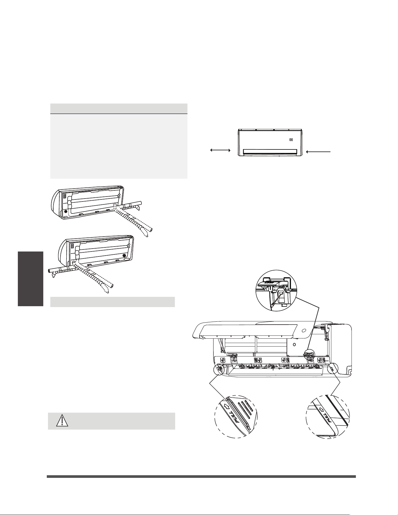
If refrigerant piping is already embedded in
the wall, do the following:
Step 1:Hook the indoor unit on the mounting
plate:
Step 2: Prepare refrigerant piping:
.PWFUPMFGUPSSJHIU
Model A
NN
JO
NN
JO
1. Keep in mind that the hooks on the mounting plate
are smaller than the holes on the back of the unit.
If you find that you don’t have ample room to connect
embedded pipes to the indoor unit, the unit can be
adjusted left or right by about 30-50mm (1.18-1.95in),
depending on the model.
CAUTION
Be extremely careful not to dent or
damage the piping while bending them
away from the unit. Any dents in the
piping will affect the unit’s performance.
Step 4: Prepare refrigerant piping
The refrigerant piping is inside an insulating
sleeve attached to the back of the unit. You must
prepare the piping before passing it through the
hole in the wall. Refer to the Refrigerant Piping
Connection section of this manual for detailed
instructions on pipe flaring and flare torque
requirements, technique, etc.
NOTE ON PIPING ANGLE
Refrigerant piping can exit the indoor unit from
four different angles:
UÊ
Left-hand side
UÊ
Left rear
UÊ
Right-hand side
UÊ
UÊ
UÊ
Right rear
When choose Left-hand side or Right-hand
side piping, please make sure that the pipes
come out horizontally so as not to affect the
lower panel installtion.
Refer to figures below for details.
1. Open and fix the position of the panel,
then, open the covers of the two lock
blocks, unscrew the screw showed in
the picture below, then hold both sides
of the lower panel in the place marked
“PULL”, pull it upwards to release the
buckles, then take the lower panel down.
Open the cover
and unscrew the
screw
NOTE ON PIPING CONNECTING
In some locations of US, a conduit tube
must be used to connect the cable.
To ensure an enough space for the pipes
running and the machine is against the
wall after installation, It is recommended
to attach the drain hose to the right-hand
side (when you’re facing the back of the unit).
AUTO COOL
e
Page 23
f
Indoor Unit
Installation
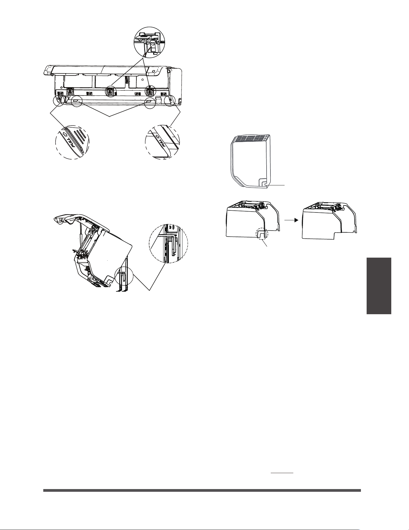
Model B
6TFUIFIPMEFSBUUIFCBDL
PGUIFVOJUBHBJOTUPOUIF
NPVOUJOHQMBUFUPQSPQVQ
UIFVOJU
Open the cover
and unscrew the
screws
Unscrew the
screws
If there is no refrigerant piping embedded in
the wall, do the following:
Step 3. Connect drain hose and refrigerant
piping (refer to Refrigerant Piping Connection
section of this manual for instructions).
Step 4. Keep pipe connection point exposed to
perform the leak test (refer to Electrical Checks
and Leak Checks section of this manual).
Step 5. After the leak test, wrap the connection
point with insulation tape.
Step 6. Remove the bracket or wedge that is
propping with insulation tape.
Step 7. Using even pressure, push down on the
bottom half of the unit. Keep pushing down
until the unit snaps onto the hooks along the
bottom of the mounting plate.
1.
Based on the position of the wall hole relative
to the mounting plate, choose the side from
which the piping will exit the unit.
2.
If the wall hole is behind the unit, keep the
knock-out panel in place. If the wall hole is to
the side of the indoor unit, remove the plastic
knock-out panel from that side of the unit.
(See figure below). This will create a slot through
which your piping can exit the unit. Use
needle nose pliers if the plastic panel is too
difficult to remove by hand.
3.
Use scissors to cut down the length of the
insulating sleeve to reveal about 40mm (1.57in)
of the refrigerant piping. This serves two purposes:
U To facilitate the Refrigerant Piping
Connection process.
U To facilitage Gas Leak Checks and enable
you to check for dents
,OPDLPVU1BOFM
DVUEFQFOEJOHPOUIF
BDUVBMTJ[FOFFEFE
*GOFFEUPDVUUIFCJHTJ[FQMBTUJD
QBOFMDVUBTTIPXOBCPWF
2. Use the holder at the back of the unit to
prop up the unit, giving you enough room
to connect the refrigerant piping, signal cable,
and drain hose.
4. Use the holder at the back of the unit to
prop up the unit, giving you enough room
to connect the refrigerant piping, signal cable,
and drain hose.
5.
Connect the indoor unit’s refrigerant piping
to the connective piping that will join the
indoor and outdoor units. Refer to the
Refrigerant Piping Connection section
of this manual for detailed instructions.
6.
Based on the position of the wall hole
relative to the mounting plate, determine the
necessary angle of your piping.
7.
Grip the refrigerant piping at the base of the bend.
8.
Slowly, with even pressure, bend the piping
towards the hole. Do not dent or damage the
piping during the process.
Page 24
Indoor Unit
Installation
DO NOT kink the drain hose.
DO NOT
create a water trap.
DO NOT put the end of drain hose in
water or a container that will collect water.
BEFORE PERFORMING ANY
ELECTRICAL WORK, READ THESE
REGULATIONS
1. All wiring must comply with local and national
electrical codes, regulations and must be
installed by a licensed electrician.
2. All electrical connections must be made according
to the Electrical Connection Diagram located on
the panels of the indoor and outdoor units.
3. If there is a serious safety issue with the power
supply, stop work immediately. Explain your
reasoning to the client, and refuse to install the
unit until the safety issue is properly resolved.
4. Power voltage should be within 90-110% of
rated voltage. Insufficient power supply can
cause malfunction, electrical shock, or fire.
5. If connecting power to fixed wiring, a surge
protector and main power switch should be
installed.
6. If connecting power to fixed wiring, a switch
or circuit breaker that disconnects all poles and
has a contact separation of at least 1/8in (3mm)
must be incorporated in the fixed wiring. The
qualified technician must use an approved
circuit breaker or switch.
7. Only connect the unit to an individual branch
circuit outlet. Do not connect another appliance
to that outlet.
8. Make sure to properly ground the air conditioner.
9. Every wire must be firmly connected. Loose
wiring can cause the terminal to overheat,
resulting in product malfunction and possible fire.
Do not let wires touch or rest against refrigerant
tubing, the compressor, or any moving parts
within the unit.
If the unit has an auxiliary electric heater, it must
be installed at least 1 meter (40in) away from
any combustible materials.
To avoid getting an electric shock, never touch
the electrical components soon after the power
supply has been turned off. After turning off
the power, always wait 10 minutes or more
before you touch the electrical components.
WARNING
BEFORE PERFORMING ANY ELECTRICAL
OR WIRING WORK, TURN OFF THE
MAIN POWER TO THE SYSTEM.
10.
11.
12.
Step 5:
Connect drain hose
Continued from Step 4, Indoor Unit Installation
By default, the drain hose is attached to the left-
hand side of unit (when you’re facing the back
of the unit). However, it can also be attached to
the right-hand side. To ensure proper drainage,
attach the drain hose on the same side that your
refrigerant piping exits the unit.
NOTE: In some locations of US, if the machine
has installed the conduit panel, please choose
right-hand side drainage.
Wrap the connection point firmly with Teflon
tape to ensure a good seal and to prevent leaks.
Remove the air filter and pour a small amount
of water into the drain pan to make sure that
water flows from the unit smoothly.
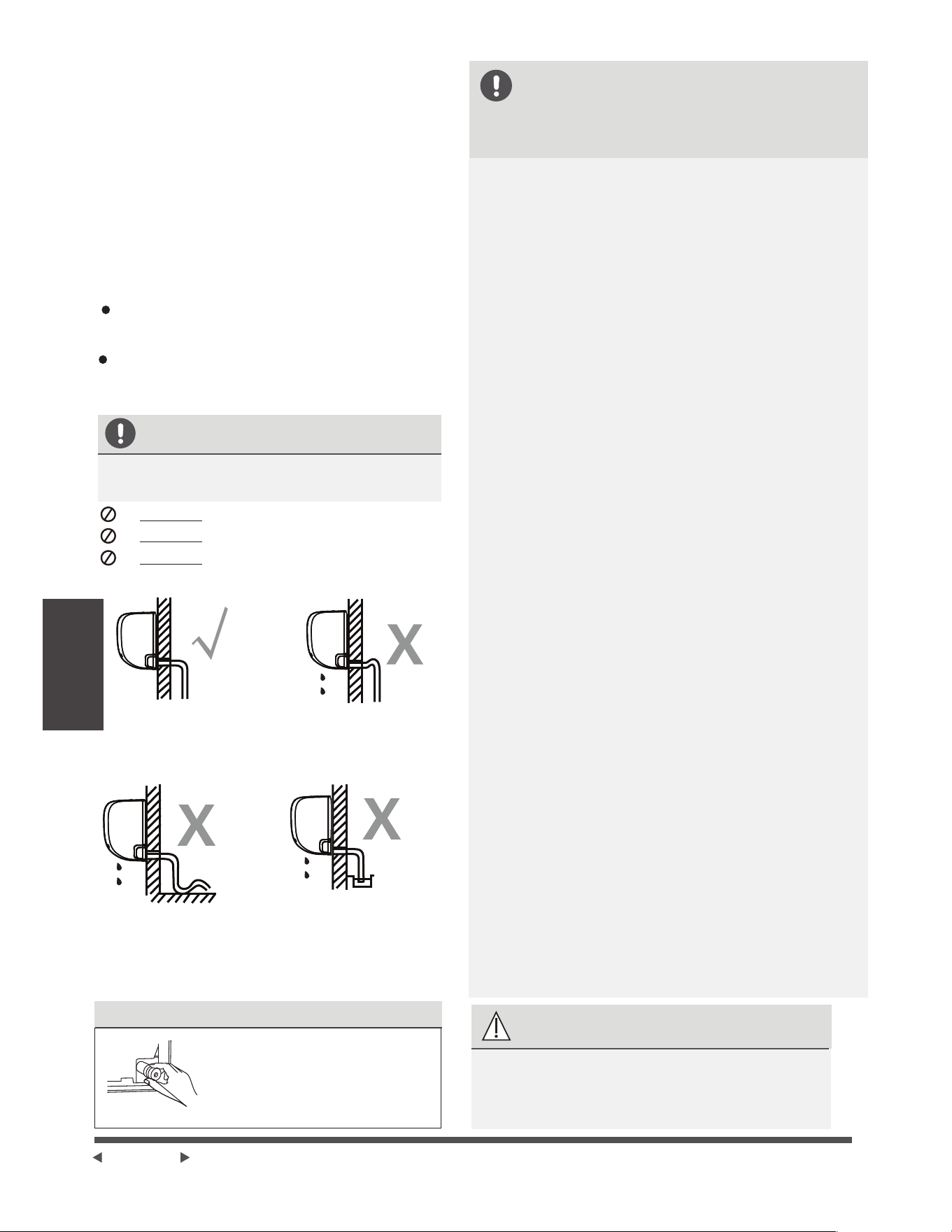
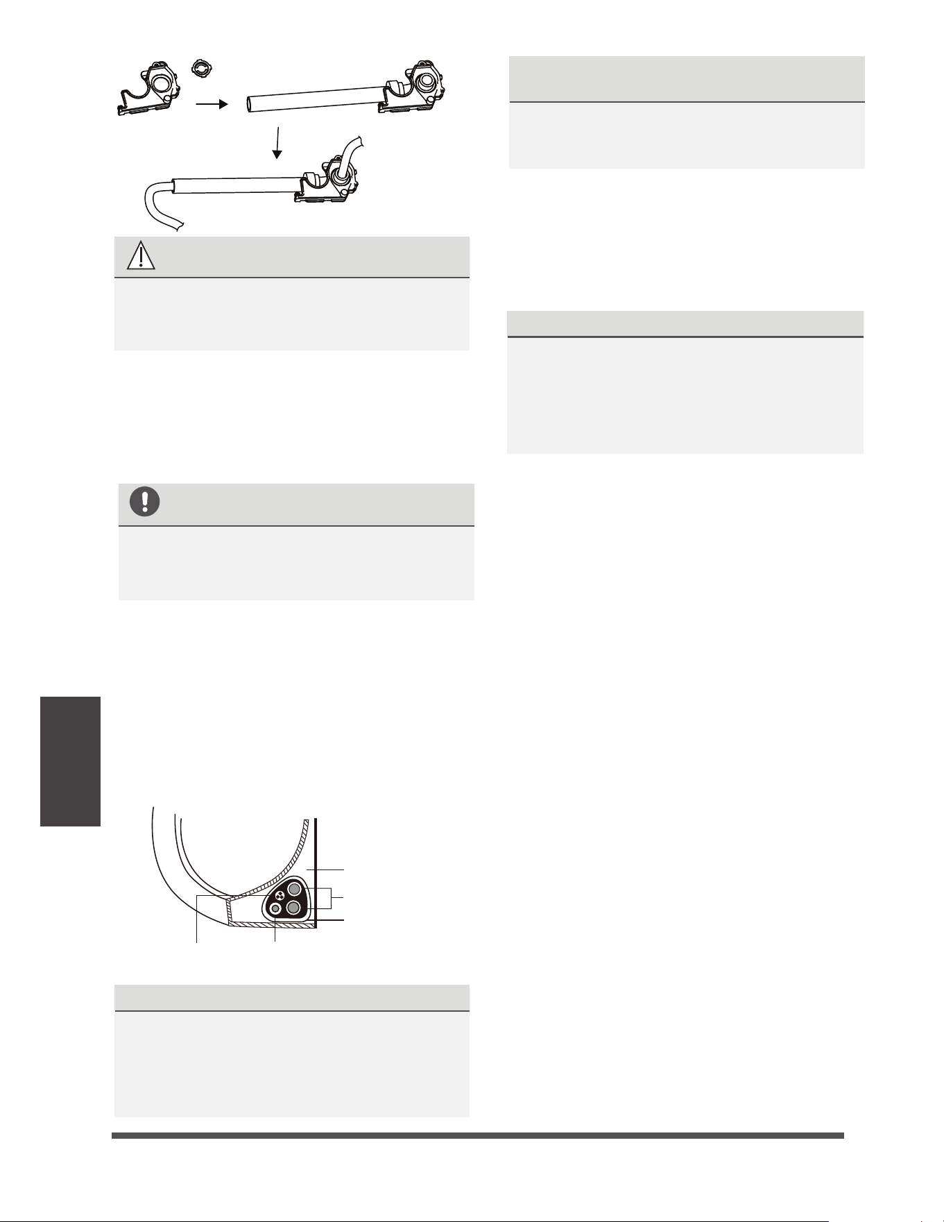
NOTE ON DRAIN HOSE PLACEMENT
Make sure to arrange the drain hose
according to the following figures.
PLUG THE UNUSED DRAIN HOLE
To prevent unwanted leaks
you must plug the unused
drain hole with the rubber
plug provided.
CORRECT
Make sure there are no kinks
or dent in drain hose to ensure
proper drainage.
NOT CORRECT
Kinks in the drain hose
will create water traps.
NOT CORRECT
Do not place the end of the
drain hose in water or in
containers that collect water.
This will prevent proper
drainage.
NOT CORRECT
Kinks in the drain hose
will create water traps.
e
Page 25
f
Indoor Unit
Installation
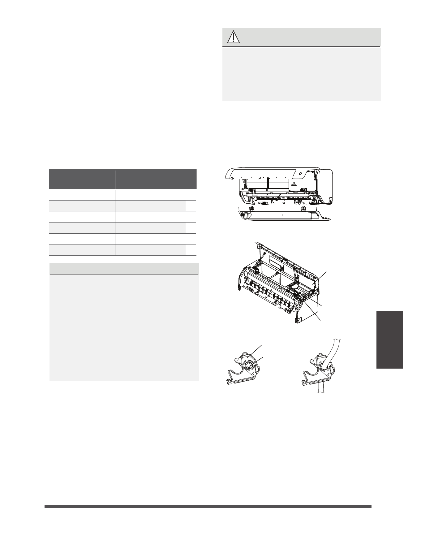
1. Open and fix the position of the panel,
then, open the covers of the two lock
blocks, unscrew the screw , then hold
both sides of the lower panel in the place
marked “PULL”, pull it upwards to release
the buckles, then take the lower panel
down(please refer to Page 22-23).
2.
Open the wire box cover to connect the cable.
First remove the knok-out panel to create a
slot through whick the conduit tube can
install. Then make the cable through the
conduit tube and connect to the indoor unit.
First open the front panel, then remove
the lower panel.
Terminal
block
open the
Wire cover
Rat baffle(some units)
Knock-out
panel
Cable
clamp
NOTE: If the size of the cable is too big, remove
the middle small plastic knock-out panel to create
a slot through which the cable can exit. If you want
to remove the chassis or drain hose, please remove
the rat baffle first.
WARNING
3.
Unscrew the cable clamp below the terminal
block and place it to the side.
4.
Facing the back of the unit, remove the plastic
panel on the bottom left-hand side.
ALL WIRING MUST BE PERFORMED
STRICTLY IN ACCORDANCE WITH THE
WIRING DIAGRAM LOCATED ON THE
BACK OF THE INDOOR UNIT S FRONT
PANEL .
’
5.
Feed the signal wire through this slot, from
the back of the unit to the front.
6.
Facing the front of the unit, connect the wire
according to the indoor unit’s wiring diagram,
connect the u-lug and firmly screw each wire
to its corresponding terminal.
In North America
Step 6: Connect signal and power cables
The signal cable enables communication between
the indoor and outdoor units. You must first choose
the right cable size before preparing it for connection.
Cable Types
UÊ
Indoor Power Cable
(if applicable):
H05VV-F or H05V2V2-F
UÊ
Outdoor Power Cable: H07RN-F or H05RN-F
UÊ
Signal Cable: H07RN-F
(Not applicable for North America)
NOTE: In North America, choose the cable type
according to the local electrical codes and regulations.
Minimum Cross-Sectional Area of
Power and Signal Cables (For reference)
Rated Current of
Appliance (A)
Nominal Cross-Sectional
Area (mm²)
> 3 and d 6
0.75
> 6 and d 10
1
> 10 and d 16
1.5
> 16 and d 25
2.5
> 25 and d 32
4
> 32 and d 40
6
CHOOSE THE RIGHT CABLE SIZE
The size of the power supply cable, signal
cable, fuse, and switch needed is determined
by the maximum current of the unit. The
maximum current is indicated on the nameplate
located on the side panel of the unit. Refer to
this nameplate to choose the right cable, fuse,
or switch.
NOTE: In North America, please choose the
right cable size according to the Minimum
Circuit Ampacity indicated on the nameplate
of the unit.
e
Page 26
f
Indoor Unit
Installation
CAUTION
DO NOT MIX UP LIVE AND NULL WIRES
This is dangerous, and can cause the air
conditioning unit to malfunction.
7.
After checking to make sure every connection
is secure, use the cable clamp to fasten the
signal cable to the unit. Screw the cable clamp
down tightly.
8.
Replace the wire cover on the front of the
unit, and the plastic panel on the back.
DRAIN HOSE MUST BE ON BOTTOM
Make sure that the drain hose is at the bottom
of the bundle. Putting the drain hose at the
top of the bundle can cause the drain pan
to overflow, which can lead to fire or water
damage.
DO NOT INTERTWINE SIGNAL CABLE WITH
OTHER WIRES
While bundling these items together, do not
intertwine or cross the signal cable with any
other wiring.
2.
Using adhesive vinyl tape, attach the drain
hose to the underside of the refrigerant pipes.
3.
Using insulation tape, wrap the signal wire,
refrigerant pipes, and drain hose tightly
together. Double-check that all items are
bundled.
DO NOT WRAP ENDS OF PIPING
When wrapping the bundle, keep the ends
of the piping unwrapped. You need to access
them to test for leaks at the end of the
installation process (refer to Electrical Checks
and Leak Checks section of this manual)
NOTE ABOUT WIRING
THE WIRING CONNECTION PROCESS MAY
DIFFER SLIGHTLY BETWEEN UNITS AND
REGIONS.
Before passing the piping, drain hose, and the
signal cable through the wall hole, you must
bundle them together to save space, protect
them, and insulate them(This may not applicable
for some locations in US).
1.
Bundle the drain hose, refrigerant pipes, and
signal cable as shown below:
*OEPPS6OJU
4QBDFCFIJOEVOJU
3FGSJHFSBOUQJQJOH
Drain hose
4JHOBMXJSF
*OTVMBUJPOUBQF
Step 7: Wrappping and cables
Step 8: Mount indoor unit
If you installed new connective piping
to the outdoor unit, do the following:
1.
If you have already passed the refrigerant
piping through the hole in the wall, proceed
to Step 4.
2.
Otherwise, double-check that the ends of the
refrigerant pipes are sealed to prevent dirt or
foreign materials from entering the pipes.
3.
Slowly pass the wrapped bundle of refrigerant
pipes, drain hose, and signal wire through the
hole in the wall.
4.
Hook the top of the indoor unit on the upper
hook of the mounting plate.
5.
Check that unit is hooked firmly on mounting
by applying slight pressure to the left and
right-hand sides of the unit. The unit should
not jiggle or shift.
6.
Using even pressure, push down on the
bottom half of the unit. Keep pushing down
until the unit snaps onto the hooks along the
bottom of the mounting plate.
7.
Again, check that the unit is firmly mounted
by applying slight pressure to the left and the
right-hand sides of the unit.
e
Page 27
f
Installation
Outdoor Unit
eWoba ni2 Nc6
DNJO
on righU
DNJO
POMFGU
DNJO
in fronU
DNJO
GSPNCBDLXBMM
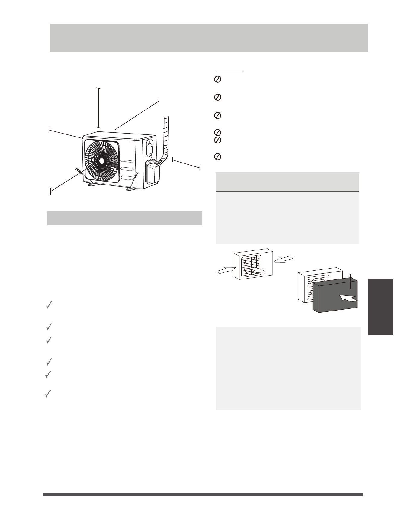
Installation Instructions – Outdoor unit
Step 1: Select installation location
Before installing the outdoor unit, you must
choose an appropriate location. The following are
standards that will help you choose an appropriate
location for the unit.
Proper installation locations meet the
following standards:
Meets all spatial requirements shown in
Installation Space Requirements above.
Good air circulation and ventilation
Firm and solid—the location can support the
unit and will not vibrate
Noise from the unit will not disturb others
Install the unit by following local codes and
regulations , there may be differ slightly
between different regions.
SPECIAL CONSIDERATIONS FOR EXTREME
WEATHER
If the unit is exposed to heavy wind:
Install unit so that air outlet fan is at a 90°
angle to the direction of the wind. If needed,
build a barrier in front of the unit to protect it
from extremely heavy winds.
See Figures below.
4USPOH
wind
4USPOHXJOE
4USPOHXJOE
If the unit is frequently exposed to heavy
rain or snow:
Build a shelter above the unit to protect
it from the rain or snow. Be careful not to
obstruct air flow around the unit.
If the unit is frequently exposed to salty air
(seaside):
Use outdoor unit that is specially designed to
resist corrosion.
Wind Baffle
Protected from prolonged periods of direct
sunlight or rain
DO NOT
install unit in the following locations:
Near an obstacle that will block air inlets
and outlets
Near a public street, crowded areas, or
where noise from the unit will disturb others
Near animals or plants that will be harmed
by hot air discharge
Near any source of combustible gas
In a location that is exposed to large
amounts of dust
In a location exposed to a excessive amounts
of salty air
Outdoor Unit Installation
Where snowfall is anticipated, take
appropriate measures to prevent ice
buildup and coil damage.
e
Page 28
f
Outdoor Unit
Installation
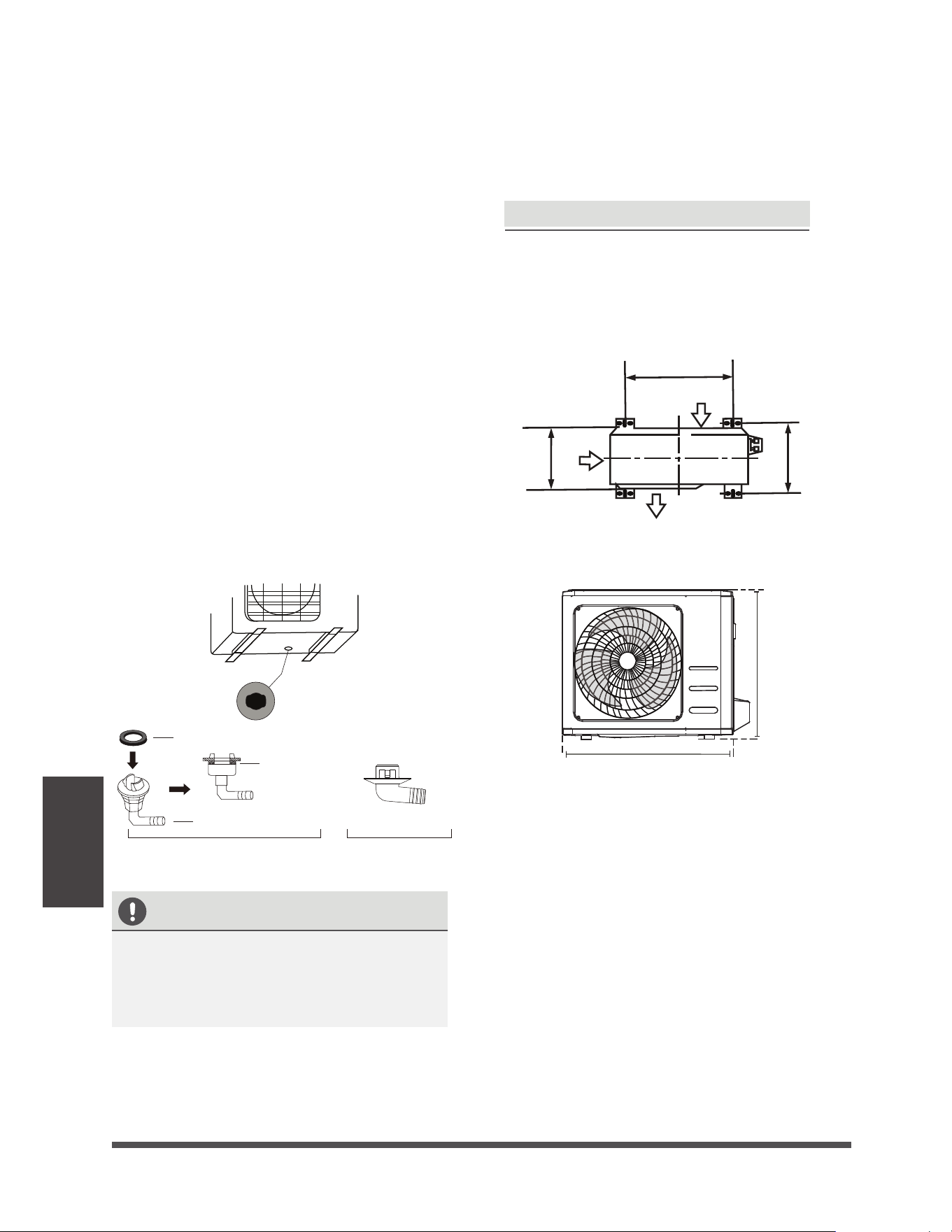
Step 2: Install drain joint(Heat pump unit only)
Before bolting the outdoor unit in place, you must
install the drain joint at the bottom of the unit.
Note that there are two different types of drain
joints depending on the type of outdoor unit.
If the drain joint comes with a rubber seal
(see Fig. A ), do the following:
1.
Fit the rubber seal on the end of the drain joint
that will connect to the outdoor unit.
2.
Insert the drain joint into the hole in the base
pan of the unit.
3.
Rotate the drain joint 90° until it clicks in place
facing the front of the unit.
4.
Connect a drain hose extension (not included)
to the drain joint to redirect water from the
unit during heating mode.
If the drain joint doesn’t come with a rubber
seal (see Fig. B ), do the following:
1.
Insert the drain joint into the hole in the base
pan of the unit. The drain joint will click in
place.
2.
Connect a drain hose extension (not included)
to the drain joint to redirect water from the
unit during heating mode.
4FBM
%SBJOKPJOU
" #
#BTFQBOIPMFPG
PVUEPPSVOJU
4FBM
IN COLD CLIMATES
In cold climates, make sure that the drain hose
is as vertical as possible to ensure swift water
drainage. If water drains too slowly, it can
freeze in the hose and flood the unit.
The outdoor unit can be anchored to the
ground or to a wall-mounted bracket with
bolt(M10). Prepare the installation base of the
unit according to the dimensions below.
A
B
D
Air inlet
Air outlet
Air inlet
8
)
Step 3: Anchor outdoor unit
UNIT MOUNTING DIMENSIONS
The following is a list of different outdoor
unit sizes and the distance between their
mounting feet. Prepare the installation base
of the unit according to the dimensions below.
e
Page 29
f
Outdoor Unit
Installation
If you will install the unit on a wall-mounted
bracket , do the following:
1.Mark the position of bracket holes based on
dimensions chart.
2. Pre-drill the holes for the expansion bolts.
3. Place a washer and nut on the end of each
expansion bolt.
4. Thread expansion bolts through holes in
mounting brackets, put mounting brackets
in position, and hammer expansion bolts into
the wall.
5. Check that the mounting brackets are level.
6. Carefully lift unit and place its mounting feet
on brackets.
7. Bolt the unit firmly to the brackets.
8.
If allowed, install the unit with rubber
gaskets to reduce vibrations and noise.
If you will install the unit on the ground or
on a concrete mounting platform, do the
following:
1. Mark the positions for four expansion bolts
based on dimensions chart.
2. Pre-drill holes for expansion bolts.
3. Place a nut on the end of each expansion bolt.
4. Hammer expansion bolts into the pre-drilled
holes.
5. Remove the nuts from expansion bolts, and
place outdoor unit on bolts.
6. Put washer on each expansion bolt, then
replace the nuts.
7. Using a wrench, tighten each nut until snug.
WARNING
WHEN DRILLING INTO CONCRETE, EYE
PROTECTION IS RECOMMENDED AT ALL
TIMES.
CAUTION
Make sure that the wall is made of solid brick,
concrete, or of similarly strong material. The
wall must be able to support at least four
times the weight of the unit.
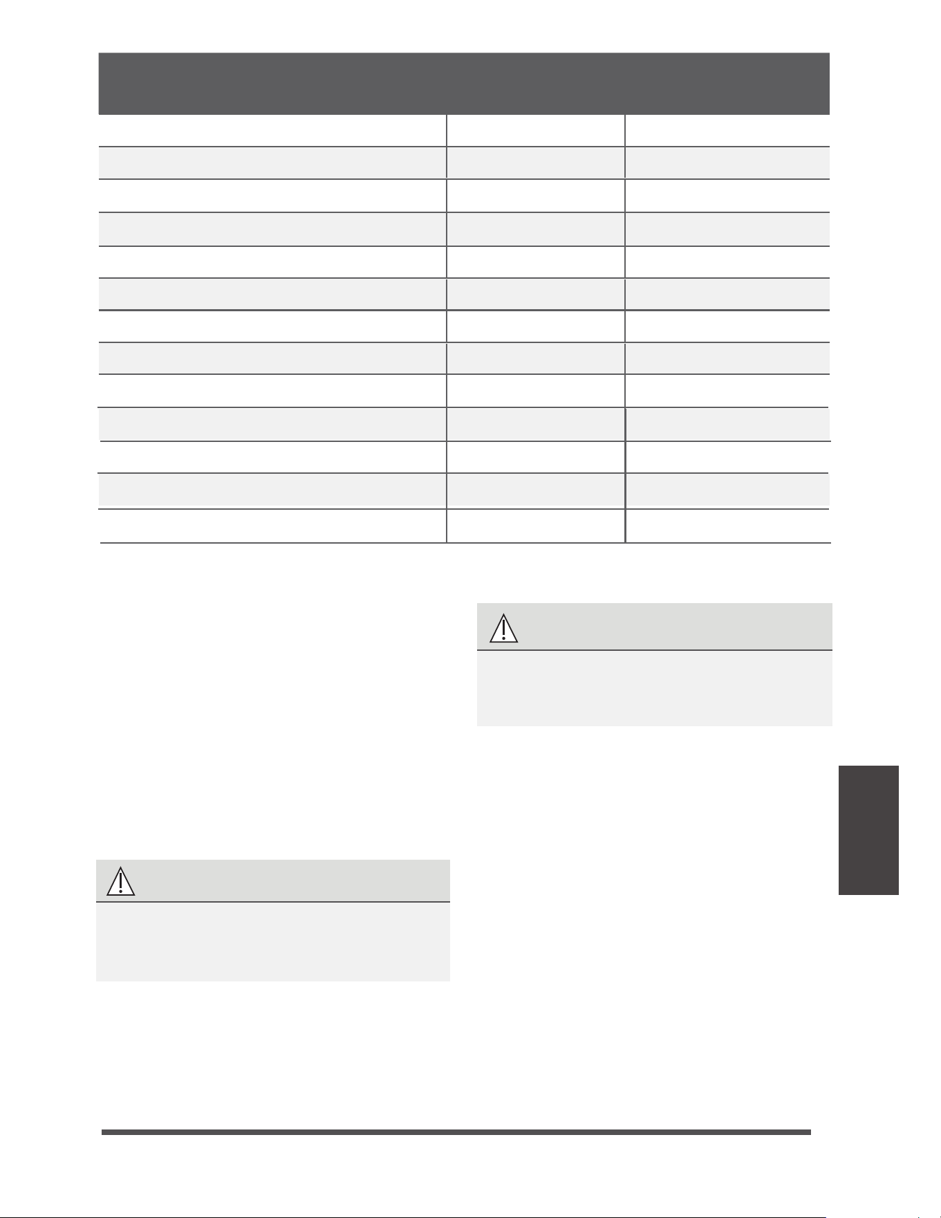
Outdoor Unit Dimensions (mm)
W x H x D
Mounting Dimensions
Distance A (mm) Distance B (mm)
681x434x285 (26.8”x 17.1”x 11.2”) 460 (18.1”) 292 (11.5”)
700x550x270 (27.5”x 21.6”x 10.6”) 450 (17.7”) 260 (10.2”)
728x555x300 (28.7”x 21.8”x 11.8”)
452 (17.8”)
302(11.9”)
765x555x303 (30.1”x 21.8”x 11.9”)
452 (17.8”)
286(11.3”)
890x673x342 (35.0”x 26.5”x 13.5”)
946x810x420 (37.2”x 31.9”x 16.5”)
663 (26.1”)
673 (26.5”)
354 (13.9”)
403 (15.9”)
946x810x410 (37.2”x 31.9”x 16.1”)
673 (26.5”)
403 (15.9”)
720x495x270 (28.3”x 19.5”x 10.6”)
452 (17.8”)
255 (10.0”)
845x702x363 (33.3”x 27.6”x 14.3”)
540 (21.3”)
350 (13.8”)
700x550x275 (27.5”x 21.6”x 10.8”)
450 (17.7”)
260 (10.2”)
770x555x300 (30.3”x 21.8”x 11.8”)
487 (19.2”)
298 (11.7”)
800x554x333 (31.5”x 21.8”x 13.1”)
514 (20.2”)
340 (13.4”)
805x554x330 (31.7”x 21.8”x 12.9”)
511 (20.1”)
317 (12.5”)
e
Page 30
f
Outdoor Unit
Installation
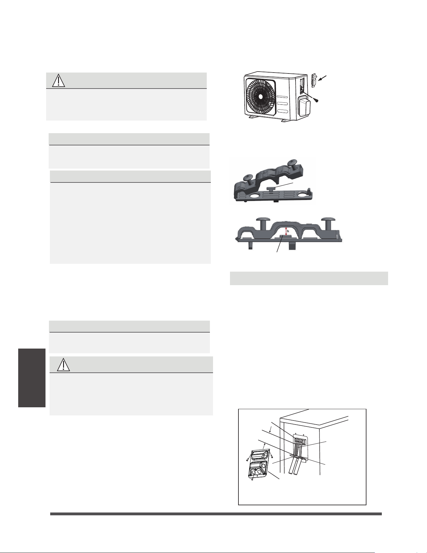
Step 4: Connect signal and power cables
The outside unit’s terminal block is protected by
an electrical wiring cover on the side of the unit.
A comprehensive wiring diagram is printed on
the inside of the wiring cover.
WARNING
1. Prepare the cable for connection:
PAY ATTENTION TO LIVE WIRE
While crimping wires, make sure you clearly
distinguish the Live (“L”) Wire from other wires.
7. Insulate unused wires with PVC electrical tape.
Arrange them so that they do not touch any
electrical or metal parts.
8. Replace the wire cover on the side of the unit,
and screw it in place.
2. Unscrew the electrical wiring cover and remove it.
3. Unscrew the cable clamp below the terminal
block and place it to the side.
4. Connect the wire according to the wiring
diagram, and firmly screw the u-lug of each
wire to its corresponding terminal.
5. After checking to make sure every connection is
secure, loop the wires around to prevent rain
water from flowing into the terminal.
6. Using the cable clamp, fasten the cable to the
unit. Screw the cable clamp down tightly.
1. Remove the wire cover from the unit by
loosening the 3 screws.
2. Dismount caps on the conduit panel.
3. Temperarily mount the conduit tubes(not
included) on the conduit panel.
4. Properly connect both the power supply and
low voltage lines to the corresponding
terminals on the terminal block.
5. Ground the unit in accordance with local codes.
6. Be sure to size each wire allowing several inches
longer than the required length for wiring.
7. Use lock nuts to secure the conduit tubes.
BEFORE PERFORMING ANY ELECTRICAL
OR WIRING WORK, TURN OFF THE MAIN
POWER TO THE SYSTEM.
WARNING
ALL WIRING WORK MUST BE PERFORMED
STRICTLY IN ACCORDANCE WITH THE
WIRING DIAGRAM LOCATED INSIDE OF
WIRE COVER OF THE OUTDOOR UNIT .
In North America
Cover
Screw
Wire Cover
Over 1.57in.(40mm)
Terminal block
Conduit panel
Connecting cable
Please select the appropriate through-hole according
to the diameter of the wire.
Three size hole: Small, Large, Medium
When the calbe is not fasten enough, use the
buckle to prop it up , so it can be clamped tightly.
Buckle
NOTE: If the cable clamp looks like the following,
please select the appropriate through-hole according
to the diameter of the wire.
USE THE RIGHT CABLE
Please choose the right cable refer to
“ Cable types” in page 25.
a. Using wire strippers, strip the rubber
jacket from both ends of cable to reveal
about 40mm (1.57in) of the wires inside.
b. Strip the insulation from the ends of the wires.
c. Using a wire crimper, crimp u-lugs on the
ends of the wires.
CHOOSE THE RIGHT CABLE SIZE
The size of the power supply cable, signal cable,
fuse, and switch needed is determined by the
maximum current of the unit. The maximum
current is indicated on the nameplate located
on the side panel of the unit.
NOTE: In North America, please choose the right
cable size according to the Minimum Circuit
Ampacity indicated on the nameplate of the unit.
MHWAL06DA/MHSZ106DA
MHWAL09DA/MHSZ109DA
Φ6.35(1/4in)
Φ6.35(1/4in)
Φ9.52(3/8in)
Φ9.52(3/8in)
Φ12.7(1/2in)
Φ16(5/8in)
MHWAL12DA/MHSZ112DA
MHWAL18DA/MHSZ118DA
MHWAL24DA/MHSZ124DA
ECR Model Liquid Side mm(in) Gas Side mm(in)
e Page 32 f
Refrigerant
Piping
Connection
6.
Place flaring tool onto the form.
7.
Turn the handle of the flaring tool clockwise
until the pipe is fully flared.
8.
Remove the flaring tool and flare form, then
inspect the end of the pipe for cracks and
even flaring.
Step 4: Connect pipes
When connecting refrigerant pipes, be careful
not to use excessive torque or to deform the
piping in any way. You should first connect the
low-pressure pipe, then the high-pressure pipe.
MINIMUM BEND RADIUS
When bending connective refrigerant piping,
the minimum bending radius is 10cm.
öDNJO
3BEJVT
Instructions for Connecting Piping to
Indoor Unit
1.
Align the center of the two pipes that you will
connect.
*OEPPSVOJUUVCJOH 'MBSFOVU 1JQF
Max.
Step 2: Remove burrs
Burrs can affect the air-tight seal of refrigerant
piping connection. They must be completely
removed.
1.
Hold the pipe at a downward angle to prevent
burrs from falling into the pipe.
2.
Using a reamer or deburring tool, remove all
burrs from the cut section of the pipe.
Pipe
Reamer
Point down
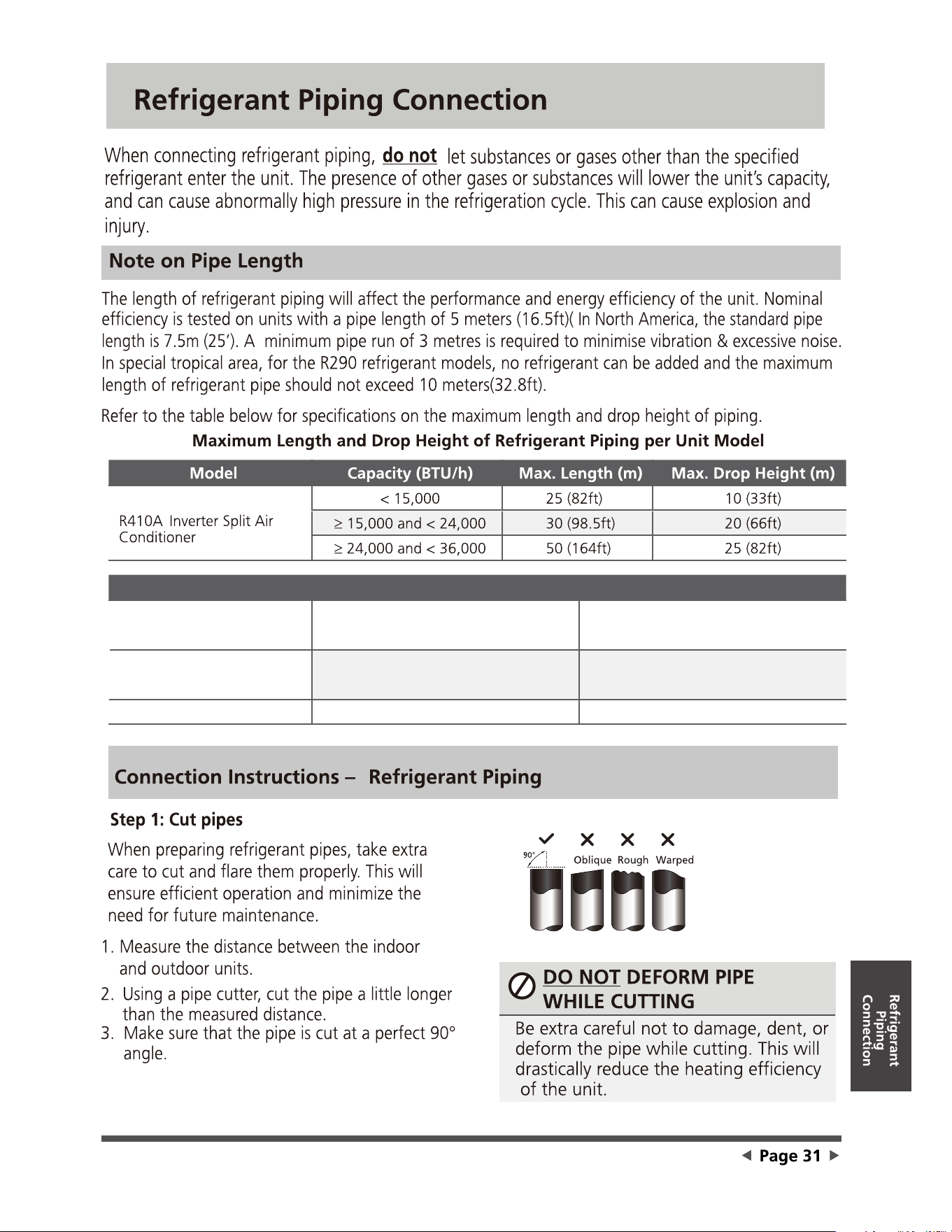
Step 3: Flare pipe ends
Proper flaring is essential to achieve an airtight
seal.
1.
After removing burrs from cut pipe, seal
the ends with PVC tape to prevent foreign
materials from entering the pipe.
2.
Sheath the pipe with insulating material.
3.
Place flare nuts on both ends of pipe. Make
sure they are facing in the right direction,
because you can’t put them on or change
their direction after flaring.
'MBSFOVU
Copper pipe
4.
Remove PVC tape from ends of pipe when
ready to perform flaring work.
5.
Clamp flare form on the end of the pipe.
The end of the pipe must extend beyond the
edge of the flare form in accordance with the
dimensions shown in the table below.
PIPING EXTENSION BEYOND FLARE FORM
Outer Diameter of
Pipe (mm)
A (mm)
Min. Max.
Ø 6.35 (Ø 0.25”)
0.7 (0.0275”) 1.3 (0.05”)
Ø 9.52 (Ø 0.375”)
1.0 (0.04”)
1.6 (0.063”)
Ø12.7 (
Ø 0.5”) 1.0 (0.04”) 1.8 (0.07”)
Ø 16 ( Ø 0.63”)
Ø 19 ( Ø 0.75”)
2.0 (0.078”) 2.2 (0.086”)
2.0 (0.078”) 2.4 (0.094”)
'MBSFGPSN
1JQF
A
e Page 33 f
Refrigerant
Piping
Connection
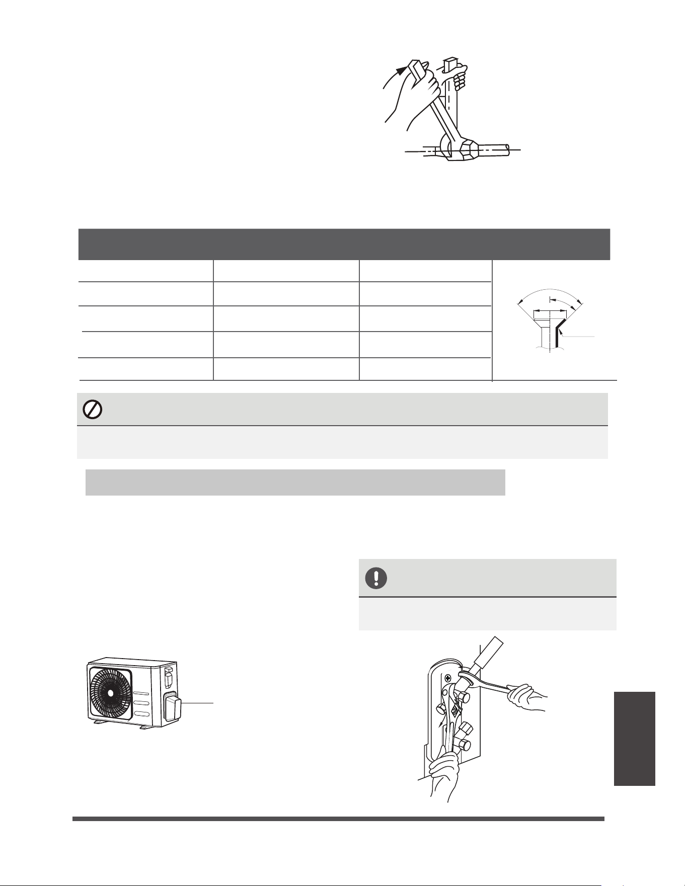
2.
Tighten the flare nut as tightly as possible by
hand.
3.
Using a spanner, grip the nut on the unit
tubing.
4.
While firmly gripping the nut on the unit
tubing, use a torque wrench to tighten the
flare nut according to the torque values in the
Torque Requirements table below. Loosen
the flaring nut slightly, then tighten again.
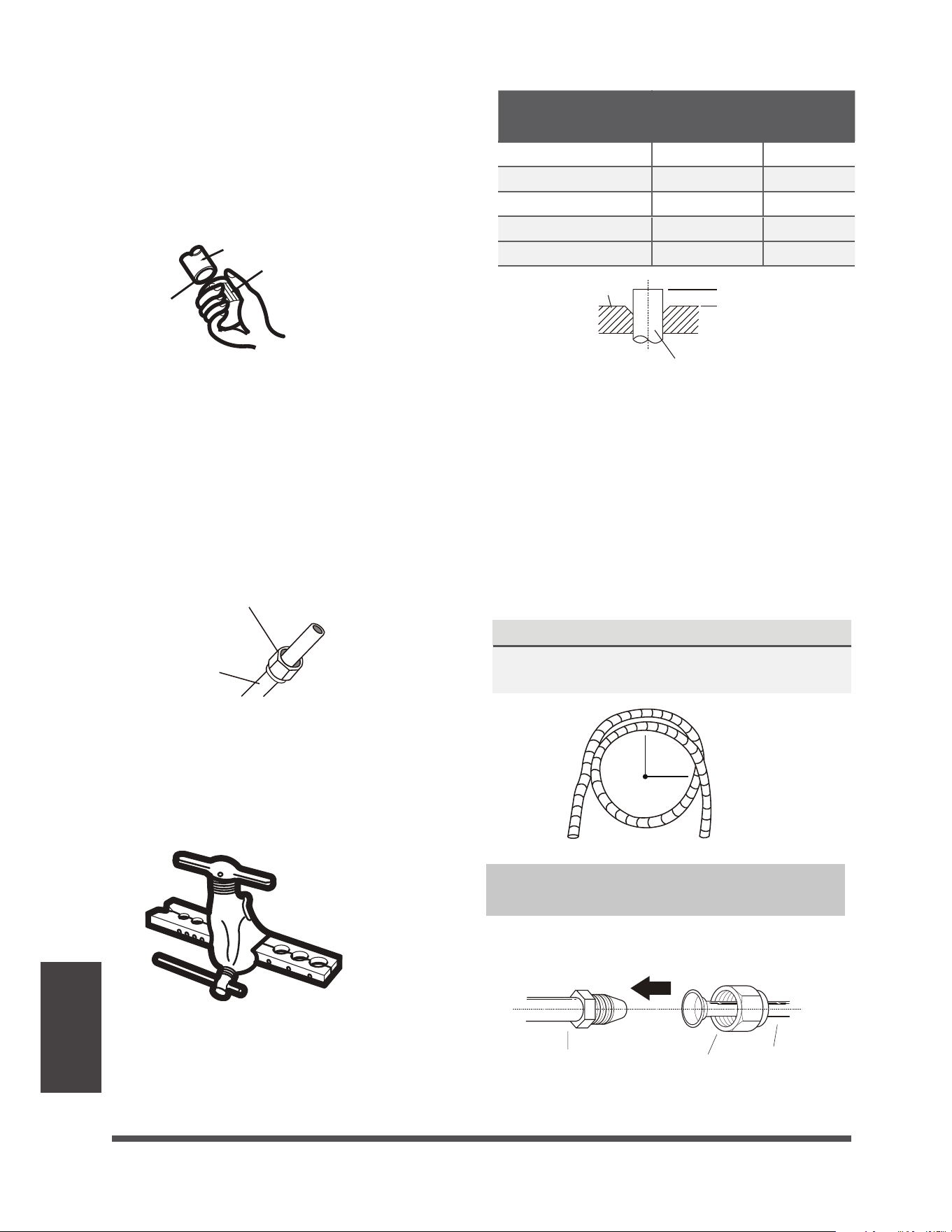
Instructions for Connecting Piping to Outdoor Unit
USE SPANNER TO GRIP MAIN
BODY OF VALVE
Torque from tightening the flare nut can snap
off other parts of valve.
TORQUE REQUIREMENTS
Outer Diameter of Pipe
(mm)
Tightening Torque
/tN
Flare dimension(B)
(mm)
Flare shape
Ø 6.35 (Ø 0.25”)
8.4~8.7 (0.33~0.34”)
13.2~13.5 (0.52~0.53”)
16.2~16.5 (0.64~0.65”)
19.2~19.7 (0.76~0.78”)
23.2~23.7 (0.91~0.93”)
18~20(180~200kgf.cm)
32~39(320~390kgf.cm)
49~59(490~590kgf.cm)
57~71(570~710kgf.cm)
67~101(670~1010kgf.cm)
Ø 9.52 (Ø 0.375”)
Ø 12.7 (Ø 0.5”)
Ø 16 (Ø 0.63”)
Ø 19 ( Ø 0.75”)
1.
Unscrew the cover from the packed valve on
the side of the outdoor unit.
2.
Remove protective caps from ends of valves.
3.
Align flared pipe end with each valve, and
tighten the flare nut as tightly as possible by
hand.
4.
Using a spanner, grip the body of the valve.
Do not grip the nut that seals the service
valve.
5.
While firmly gripping the body of the valve,
use a torque wrench to tighten the flare nut
according to the correct torque values.
6.
Loosen the flaring nut slightly, then tighten
again.
7.
Repeat Steps 3 to 6 for the remaining pipe.
DO NOT USE EXCESSIVE TORQUE
Excessive force can break the nut or damage the refrigerant piping. You must not exceed
torque requirements shown in the table above.
Valve cover
R0.4~0. 8
45
°
±
2
90
°
±
4
B
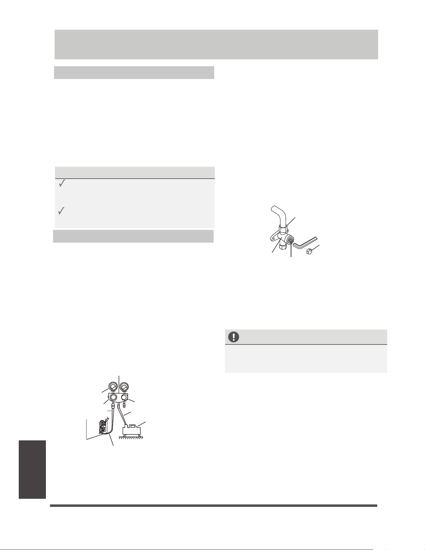
Air Evacuation
Preparations and Precautions
Air and foreign matter in the refrigerant circuit can
cause abnormal rises in pressure, which can damage
the air conditioner, reduce its efficiency, and cause
injury. Use a vacuum pump and manifold gauge to
evacuate the refrigerant circuit, removing any
non-condensable gas and moisture from the system.
Evacuation should be performed upon initial
installation and when unit is relocated.
BEFORE PERFORMING EVACUATION
Check to make sure the connective pipes
between the indoor and outdoor units
are connected properly .
Check to make sure all wiring is connected
properly.
Evacuation Instructions
.BOJGPME(BVHF
Compound
gauge
-76cmHg
Low pressure
valve
High pressure
valve
Pressure hose /
Charge hose
Charge hose
Vacuum
pump
Pressure gauge
Low pressure valve
1.
Connect the charge hose of the manifold
gauge to service port on the outdoor unit’s
low pressure valve.
Connect another charge hose from the
manifold gauge to the vacuum pump.
Open the Low Pressure side of the manifold
gauge. Keep the High Pressure side closed.
Turn on the vacuum pump to evacuate the
system.
Run the vacuum for at least 15 minutes, or
until the Compound Meter reads -76cmHG
(-10 Pa).
2.
3.
4.
5.
5
6.
Close the Low Pressure side of the manifold
gauge, and turn off the vacuum pump.
7.
Wait for 5 minutes, then check that there
has been no change in system pressure.
8.
If there is a change in system pressure, refer
to Gas Leak Check section for information
on how to check for leaks. If there is no
change in system pressure, unscrew the cap
from the packed valve (high pressure valve).
9.
Insert hexagonal wrench into the packed valve
(high pressure valve) and open the valve by
turning the wrench in a 1/4 counterclockwise
turn. Listen for gas to exit the system, then
close the valve after 5 seconds.
10.
Watch the Pressure Gauge for one minute
to make sure that there is no change in
pressure. The Pressure Gauge should read
slightly higher than atmospheric pressure.
'MBSFOVU
Cap
WBMWFCPEZ
WBMWFTUFN
11.
Remove the charge hose from the service port.
12.
Using hexagonal wrench, fully open both the
high pressure and low pressure valves.
13.
Tighten valve caps on all three valves (service
port, high pressure, low pressure) by hand.
You may tighten it further using a torque
wrench if needed.
OPEN VALVE STEMS GENTLY
When opening valve stems, turn the hexagonal
wrench until it hits against the stopper. Do not
try to force the valve to open further.
Air Evacuation
e
Page 34
f
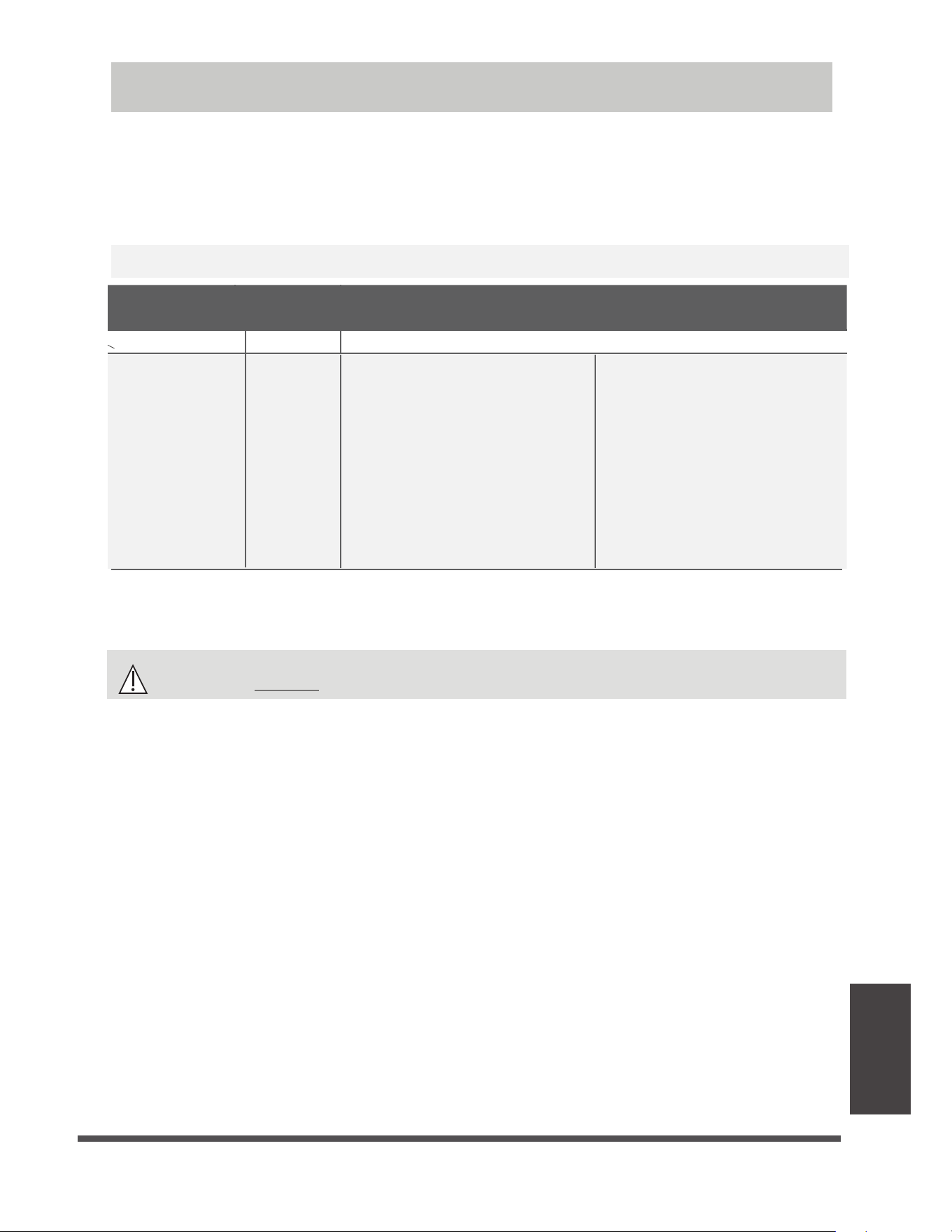
e Page 35 f
Air Evacuation
Note on Adding Refrigerant
Some systems require additional charging depending on pipe lengths. The standard pipe length varies
according to local regulations. For example, in North America, the standard pipe length is 7.5m (25’).
In other areas, the standard pipe length is 5m (16‘). The refrigerant should be charged from the service
port
on the outdoor unit’s low pressure valve.
The additional refrigerant to be charged can be
calculated using the following formula:
CAUTION
DO NOT mix refrigerant types.
For R290 refrigerant unit, the total amount of refrigerant to be charged is no more than:
387g(<=9000Btu/h), 447g(>9000Btu/h and <=12000Btu/h), 547g(>12000Btu/h and <=18000Btu/h),
632g(>18000Btu/h and <=24000Btu/h).
ADDITIONAL REFRIGERANT PER PIPE LENGTH
Connective Pipe
Length (m)
Air Purging
Method
Additional Refrigerant
< Standard pipe length Vacuum Pump N/A
> Standard pipe
length
Vacuum Pump
Liquid Side: Ø 6.35 (ø 0.25”)
R32:
(Pipe length – standard length) x 12g/m
(Pipe length – standard length) x 0.13oZ/ft
R290:
R290:
(Pipe length – standard length) x 10g/m
(Pipe length – standard length) x 0.10oZ/ft
Liquid Side: Ø 9.52 (ø 0.375”)
R32:
(Pipe length – standard length) x 24g/m
(Pipe length – standard length) x 0.26oZ/ft
(Pipe length – standard length) x 18g/m
(Pipe length – standard length) x 0.19oZ/ft
R410A:
R410A:
(Pipe length – standard length) x 15g/m
(Pipe length – standard length) x 0.16oZ/ft
(Pipe length – standard length) x 30g/m
(Pipe length – standard length) x 0.32oZ/ft
R22:
(Pipe length – standard length) x 20g/m
(Pipe length – standard length) x 0.21oZ/ft
R22:
(Pipe length – standard length) x 40g/m
(Pipe length – standard length) x 0.42oZ/ft
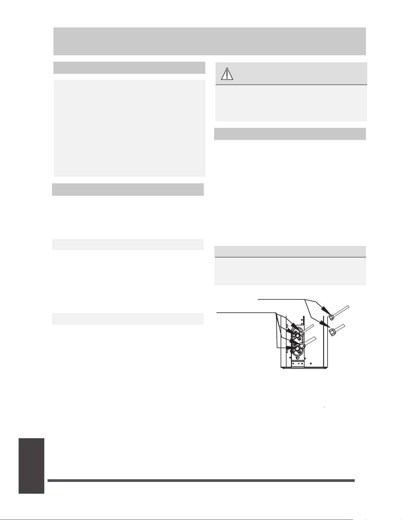
e Page 36 f
Electrical and
Gas Leak Checks
Electrical Safety Checks
After installation, confirm that all electrical wiring
is installed in accordance with local and national
regulations, and according to the Installation
Manual.
BEFORE TEST RUN
Check Grounding Work
Measure grounding resistance by visual detection
and with grounding resistance tester. Grounding
resistance must be less than 0.1Ω.
Note: This may not be required for some
locations in North America.
DURING TEST RUN
Check for Electrical Leakage
During the Test Run, use an electroprobe and
multimeter to perform a comprehensive electrical
leakage test.
If electrical leakage is detected, turn off the unit
immediately and call a licensed electrician to find
and resolve the cause of the leakage.
Note: This may not be required for some
locations in North America.
Gas Leak Checks
There are two different methods to check for gas
leaks.
Soap and Water Method
Using a soft brush, apply soapy water or liquid
detergent to all pipe connection points on the
indoor unit and outdoor unit. The presence of
bubbles indicates a leak.
Leak Detector Method
If using leak detector, refer to the device’s
operation manual for proper usage instructions.
AFTER PERFORMING GAS LEAK CHECKS
After confirming that the all pipe connection
points DO NOT leak, replace the valve cover on
the outside unit.
WARNING – RISK OF
ELECTRIC SHOCK
ALL WIRING MUST COMPLY WITH LOCAL
AND NATIONAL ELECTRICAL CODES,
AND MUST BE INSTALLED BY A LICENSED
ELECTRICIAN.
Before Test Run
Only perform test run after you have completed
the following steps:
UÊ
Electrical Safety Checks – Confirm that
the unit’s electrical system is safe and
operating properly
UÊ
Gas Leak Checks – Check all flare nut
connections and confirm that the system is
not leaking
UÊ
Confirm that gas and liquid (high and low
pressure) valves are fully open
A: Low pressure stop valve
B: High pressure stop valve
C& D: Indoor unit flare nuts
Check-point of indoor unit
Check-point of outdoor unit
A
B
C
D
Electrical and Gas Leak Checks
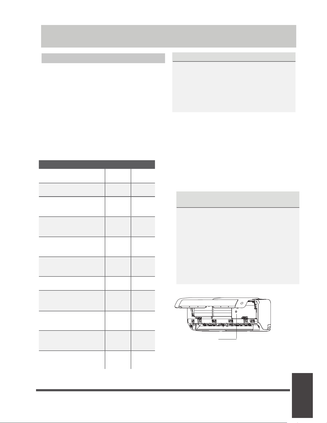
e Page 37 f
Test Run
Test Run Instructions
You should perform the Test Run for at least 30
minutes.
1.
Connect power to the unit.
2.
Press the ON/OFF button on the remote
controller to turn it on.
3.
Press the MODE button to scroll through the
following functions, one at a time:
UÊ
COOL – Select lowest possible temperature
UÊ
HEAT – Select highest possible temperature
4.
Let each function run for 5 minutes, and
perform the following checks:
List of Checks to Perform PASS/FAIL
No electrical leakage
Unit is properly grounded
All electrical terminals
properly covered
Indoor and outdoor units
are solidly installed
All pipe connection
points do not leak
Outdoor
(2):
Indoor
(2):
Water drains properly
from drain hose
All piping is properly
insulated
Unit performs COOL
function properly
Unit performs HEAT
function properly
Indoor unit louvers
rotate properly
Indoor unit responds to
remote controller
DOUBLE-CHECK PIPE CONNECTIONS
During operation, the pressure of the
refrigerant circuit will increase. This may
reveal leaks that were not present during your
initial leak check. Take time during the Test
Run to double-check that all refrigerant pipe
connection points do not have leaks. Refer to
Gas Leak Check section for instructions.
5.
After the Test Run is successfully completed,
and you confirm that all checks points in List
of Checks to Perform have PASSED, do the
following:
a.
Using remote control, return unit to
normal operating temperature.
b.
Using insulation tape, wrap the indoor
refrigerant pipe connections that you
left uncovered during the indoor unit
installation process.
IF AMBIENT TEMPERATURE IS BELOW 17°C
(62°F)
You can’t use the remote controller to turn
on the COOL function when the ambient
temperature is below 16°C. In this instance,
you can use the MANUAL CONTROL button
to test the COOL function.
Test Run
1.
The MANUAL CONTROL button is located
on the right-hand side panel of the unit.
Press the button 2 times to select the
COOL function.
Perform Test Run as normal.
2.
3.
.BOVBMDPOUSPM
CVUUPO
AUTO COOL

e
Page 38
f
Packing and
unpacking the
unit
Instructions for packing and unpacking the unit:
Unpacking:
Indoor unit:
1.Cut the sealing tape on the carton with a knife, one cut on the left, one cut in the middle and one
cut on the right.
2.Use the vice to take out the sealing nails on the top of the carton.
3.Open the carton.
4.Take out the middle support plate if it is included.
5.Take out the accessory package, and take out the connecting wire if it is included.
6.Lift the machine out of the carton and lay it flat.
7.Remove the left and right package foam or the upper and lower packaging foam, untie the
packaging bag.
Outdoor Unit
1.Cut the packing belt.
2.Take the unit out of the carton.
3.Remove the foam from the unit.
4.Remove the packaging bag from the unit.
Packing:
Indoor unit:
1.Put the indoor unit into the packing bag.
2.Attach the left and right package foam or the upper and lower packaging foam to the unit.
3.Put the unit into the carton, then put accessory package in.
4.Close the carton and seal it with the tape.
5.Using the packing belt if necessary.
Outdoor unit:
1.Put the outdoor unit into the packing bag.
2.Put the bottom foam into the box.
3.Put the unit into the carton, then put the upper packaging foam on the unit.
4.Close the carton and seal it with the tape.
5.Using the packing belt if necessary.
NOTE: Please keep all packaging items if you may need in the future.
Packing and unpacking the unit


The design and specifications are subject to change without prior notice for
product improvement. Consult with the sales agency or manufacturer for details.
Any updates to the manual will be uploaded to the service website, please check
for the latest version.
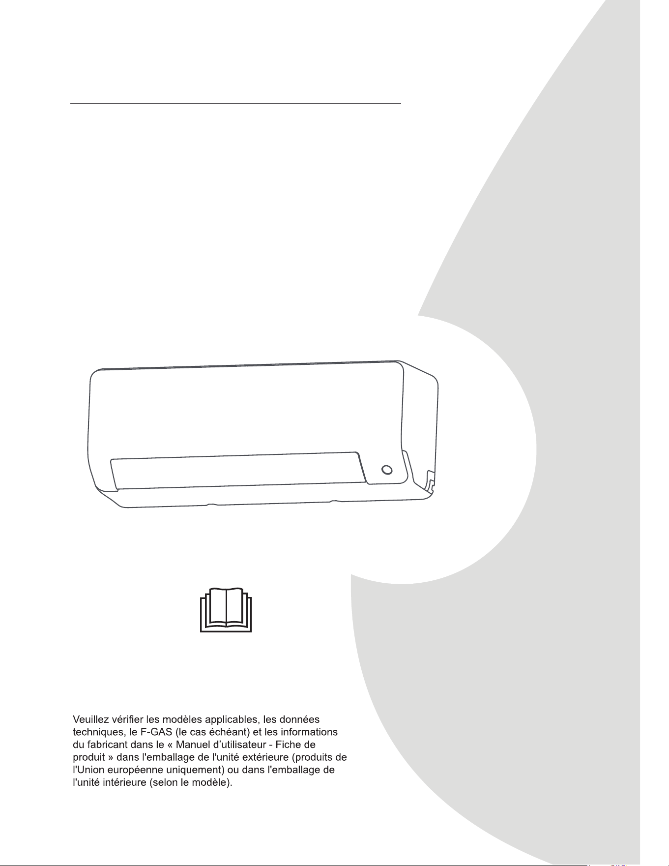
NOTE IMPORTANTE :
Lisez attentivement ce manuel et le MANUEL DE
SÉCURITÉ (le cas échéant) avant d'installer ou d'utiliser
votre nouvelle unité de climatisation. Veillez à conserver ce
manuel pour toute référence ultérieure.
Manuel d’utilisateur &
Manuel d’installation
CLIMATISEUR DU TYPE SPLIT
MHWAL Series
6-24 kBtu/h

Page 2
1S¤DBVUJPOTEFT¤DVSJU¤ ......................................................................04
Manuel d'Utilisateur
6SpFL¿FDWLRQVHWIRQFWLRQVGHO¶XQLWp ............................................... 08
$I¿FKDJHGXQLWpLQWpULHXUH ....................................................................................................................................08
2. Température de fonctionnement ............................................................................................................................09
$XWUHVIRQFWLRQV .....................................................................................................................................................10
5pJODJHGHODQJOHGXÀX[GDLU..............................................................................................................................11
)RQFWLRQQHPHQWPDQXHOVDQVWpOpFRPPDQGH ....................................................................................................11
Entretien et Maintenance ...................................................................12
Dépannage ..........................................................................................14
Table des Matières

Page 3
Manuel d’installation
Accessoires ....................................................................................... 17
Résumé de l’installation - Unité intérieure ...................................... 18
Pièces de l’unité ................................................................................ 19
Installation de l’unité intérieure ....................................................... 20
6pOHFWLRQQHUO¶HPSODFHPHQWGHO¶LQVWDOODWLRQ ..................................................................................................... 20
)L[HUODSODTXHGHPRQWDJHDXPXU ..................................................................................................................20
3HUFHUXQWURXDXPXUSRXUODWX\DXWHULHGHFRQQH[LRQ ................................................................................... 21
3UpSDUHUODWX\DXWHULHGHUpIULJpUDQW.................................................................................................................22
&RQQHFWHUOHVWX\DX[GHGUDLQDJH ....................................................................................................................24
&RQQHFWHUOHFkEOHGHVLJQDO ........................................................................................................................... 25
(QURXOHUODWX\DXWHULHHWOHVFkEOHV ..................................................................................................................26
,QVWDOOHUO¶XQLWpLQWpULHXUH...................................................................................................................................27
Installation de l’unité extérieure....................................................... 27
6pOHFWLRQQHUO¶HPSODFHPHQWGHO¶LQVWDOODWLRQ ..................................................................................................... 27
,QVWDOOHUOHMRLQWGHGUDLQDJH..............................................................................................................................28
)L[HUO¶XQLWpH[WpULHXUH ......................................................................................................................................28
&RQQHFWHUOHVFkEOHVGHVLJQDOHWDOLPHQWDWLRQ ................................................................................................ 30
Raccordement de la tuyauterie de réfrigérant ................................ 31
$1RWHVXUODORQJXHXUGHWX\DX .........................................................................................................................31
%,QVWUXFWLRQVGHUDFFRUGHPHQW7X\DXWHULHGHUpIULJpUDQW ................................................................................ 31
1. Couper le tuyau ...........................................................................................................................................31
(QOHYHUOHVEDYXUHV ......................................................................................................................................32
eYDVHUOHVH[WUpPLWpVGHVWX\DX[ .................................................................................................................32
&RQQHFWHUOHVWX\DX[ ....................................................................................................................................32
Évacuation d’air ................................................................................. 34
,QVWUXFWLRQVG¶pYDFXDWLRQ ..................................................................................................................................34
1RWHUHODWLYHjO¶DMRXWGHUpIULJpUDQW..................................................................................................................35
9pUL¿FDWLRQGHVIXLWHVGHJD]HWG¶pOHFWULFLWp .................................. 36
Mise en service .................................................................................. 37
Emballage et déballage de l’unité .................................................... 38
Page 4
Précautions de
sécurité
Précautions de sécurité
/LVH]OHVQS¤DBVUJPOTGHVpFXULWpDYDQWO¶XWLOLVDWLRQHWO¶LQVWDOODWLRQ
Une installation incorrecte due au non-respect des instructions peut causer de graves dommages ou
des blessures.
/DJUDYLWpGHVGRPPDJHVRXEOHVVXUHVSRWHQWLHOVHVWFODVVpHSDUAVERTISSEMENT ou par ATTENTION.
AVERTISSEMENT
&HV\PEROHLQGLTXHODSRVVLELOLWpGH
GRPPDJHVFRUSRUHOVRXGHSHUWHVGHYLHV
humaines.
ATTENTION
&HV\PEROHLQGLTXHODSRVVLELOLWpGHGRPPDJHV
PDWpULHOVRXGHFRQVpTXHQFHVJUDYHV
AVERTISSEMENT
&HWDSSDUHLOSHXWrWUHXWLOLVpSDUGHVHQIDQWVkJpVGHDQVHWSOXVHWSDUGHVSHUVRQQHVD\DQWGHVFDSDFLWpV
SK\VLTXHVVHQVRULHOOHVRXPHQWDOHVUpGXLWHVRXPDQTXDQWGH[SpULHQFHHWGHFRQQDLVVDQFHVjFRQGLWLRQ
qu'elles aient été supervisées ou qu'elles aient reçu des instructions concernant l'utilisation de l'appareil de
PDQLqUHVUHHWTXHOOHVFRPSUHQQHQWOHVULVTXHVHQFRXUXV/HVHQIDQWVQHGRLYHQWSDVMRXHUDYHFO¶DSSDUHLO
/HQHWWR\DJHHWO¶HQWUHWLHQGHVXWLOLVDWHXUVQHGRLYHQWSDVrWUHHIIHFWXpVSDUGHVHQIDQWVVDQVVXUYHLOODQFH
H[LJHQFHVGHODQRUPH(1
&HWDSSDUHLOQ¶HVWSDVGHVWLQpjrWUHXWLOLVpSDUGHVSHUVRQQHV\FRPSULVGHVHQIDQWVGRQWOHVFDSDFLWpV
SK\VLTXHVVHQVRULHOOHVRXPHQWDOHVVRQWUpGXLWHVRXTXLPDQTXHQWG¶H[SpULHQFHHWGHFRQQDLVVDQFHVVDXI
VLHOOHVRQWpWpVXSHUYLVpHVRXLQVWUXLWHVVXUO¶XWLOLVDWLRQGHO¶DSSDUHLOSDUXQHSHUVRQQHUHVSRQVDEOHGHOHXU
sécurité. Les enfants doivent être surveillés pour s'assurer qu'ils ne jouent pas avec l'appareil.
AVERTISSEMENTS POUR L'UTILISATION DU PRODUIT
Ɣ (QFDVG¶DQRPDOLHFRPPHXQHRGHXUGHEUOXUHLOIDXWpWHLQGUHLPPpGLDWHPHQWO¶XQLWpHWGpEUDQFKHU
O¶DOLPHQWDWLRQ$SSHOH]YRWUHUHYHQGHXUSRXUGHVLQVWUXFWLRQVD¿QG¶pYLWHUOHFKRFpOHFWULTXHO¶LQFHQGLHRX
OHVEOHVVXUHV
Ɣ Ne pasLQVpUHUOHVGRLJWVOHVWLJHVRXDXWUHVREMHWVGDQVO¶HQWUpHRXODVRUWLHG¶DLU&HODSHXWFDXVHUGHV
EOHVVXUHVFDUOHYHQWLODWHXUSHXWWRXUQHUjKDXWHYLWHVVH
Ɣ Ne pasXWLOLVHUGHVSUD\VLQÀDPPDEOHVWHOVTXHODODTXHSRXUOHVFKHYHX[ODODTXHRXODSHLQWXUHSUqVGH
O¶XQLWp&HODSHXWSURYRTXHUXQLQFHQGLHRXXQHFRPEXVWLRQ
Ɣ Ne pasIDLUHIRQFWLRQQHUOHFOLPDWLVHXUjSUR[LPLWpRXDXWRXUGHVJD]FRPEXVWLEOHV/HVJD]pPLVSHXYHQW
V¶DFFXPXOHUDXWRXUGHO¶DSSDUHLOHWSURYRTXHUXQHH[SORVLRQ
Ɣ Ne pasIDLUHIRQFWLRQQHUOHFOLPDWLVHXUGDQVXQHSLqFHKXPLGHWHOOHTX¶XQHVDOOHGHEDLQRXXQH
EXDQGHULH8QHH[SRVLWLRQH[FHVVLYHjO¶HDXSHXWSURYRTXHUXQFRXUWFLUFXLWGHVFRPSRVDQWVpOHFWULTXHV
Ɣ Ne pasH[SRVHUYRWUHFRUSVGLUHFWHPHQWjO¶DLUIUDLVSHQGDQWXQHSpULRGHGHWHPSVSURORQJpH
Ɣ Ne pas laisser les enfants jouer autour du climatiseur. Les enfants doivent être surveillés à tout moment
DXWRXUGHO¶XQLWp
Ɣ 6LOHFOLPDWLVHXUHVWXWLOLVpDYHFGHVEUOHXUVRXG¶DXWUHVXQLWpVGHFKDXIIDJHDpUH]HQWLqUHPHQWODVDOOH
SRXUpYLWHUXQHFDUHQFHHQR[\JqQH
Ɣ 'DQVFHUWDLQVHQYLURQQHPHQWVIRQFWLRQQHOVWHOVTXHOHVFXLVLQHVOHVVDOOHVGHVHUYHXUVHWFO¶XWLOLVDWLRQ
G¶XQLWpVGHFOLPDWLVDWLRQVSpFLDOHPHQWFRQoXHVHVWIRUWHPHQWUHFRPPDQGpH
$9(57,66(0(176'(1(772<$*((7'(0$,17(1$1&(
Ɣ eWHLJQH]OHGLVSRVLWLIHWGpEUDQFKH]O¶DOLPHQWDWLRQDYDQWOHQHWWR\DJH/DQpJOLJHQFHGHFHWWHRSpUDWLRQ
peut provoquer un choc électrique.
Ɣ Ne pasQHWWR\HUOHFOLPDWLVHXUDYHFGHVTXDQWLWpVH[FHVVLYHVG¶HDX
Ɣ Ne pasQHWWR\HUOHFOLPDWLVHXUDYHFGHVSURGXLWVGHQHWWR\DJHLQÀDPPDEOHV/HVSURGXLWVGHQHWWR\DJH
FRPEXVWLEOHVSHXYHQWSURYRTXHUXQLQFHQGLHRXXQHGpIRUPDWLRQ
Page 5
Précautions de
sécurité
ATTENTION
Ɣ eWHLQGUHOHFOLPDWLVHXUHWGpEUDQFKHUO¶DOLPHQWDWLRQVLYRXVQHO¶XWLOLVH]SDVSHQGDQWXQHORQJXHSpULRGH
Ɣ eWHLJQH]HWGpEUDQFKH]O¶XQLWpSHQGDQWOHVWHPSrWHV
Ɣ $VVXUH]YRXVTXHODFRQGHQVDWLRQGHO¶HDXSXLVVHV¶pFRXOHUVDQVHQWUDYHGHO¶XQLWp
Ɣ Ne pas faire fonctionner le climatiseur avec les mains mouillées. Cela peut provoquer un choc électrique.
Ɣ Ne pasXWLOLVHUO¶XQLWpjG¶DXWUHV¿QVTXHO¶XWLOLVDWLRQSUpYXH
Ɣ Ne pasPRQWHUVXURXSODFHUGHVREMHWVVXUOHGHVVXVGHO¶XQLWpH[WpULHXUH
Ɣ Ne pasODLVVHUOHFOLPDWLVHXUIRQFWLRQQHUSHQGDQWGHORQJXHVSpULRGHVDYHFGHVSRUWHVRXGHVIHQrWUHV
RXYHUWHVRXORUVTXHO¶KXPLGLWpHVWWUqVpOHYpH
$9(57,66(0(176e/(&75,48(6
Ɣ 8WLOLVH]XQLTXHPHQWOHFkEOHG¶DOLPHQWDWLRQVSpFL¿p6LOHFkEOHG¶DOLPHQWDWLRQHVWHQGRPPDJpFHFkEOH
GRLWrWUHUHPSODFpSDUOHIDEULFDQWVRQDJHQWGHVHUYLFHRXGHVSHUVRQQHVGHTXDOL¿FDWLRQVLPLODLUHSRXU
éviter tout risque.
Ɣ *DUGH]OD¿FKHG¶DOLPHQWDWLRQSURSUH(QOHYH]WRXWHODSRXVVLqUHRXODVDOHWpV¶DFFXPXODQWVXURXDXWRXU
GHOD¿FKH'HV¿FKHVVDOHVSHXYHQWSURYRTXHUXQLQFHQGLHRXXQFKRFpOHFWULTXH
Ɣ Ne pasWLUHUOHFkEOHG¶DOLPHQWDWLRQSRXUGpEUDQFKHUO¶XQLWp7HQH]IHUPHPHQWOD¿FKHHWUHWLUHUODGHOD
SULVH/HWLUDJHGLUHFWVXUOHFkEOHSHXWO¶HQGRPPDJHUHWSURYRTXHUXQLQFHQGLHRXXQFKRFpOHFWULTXH
Ɣ Ne pasPRGL¿HUODORQJXHXUGXFkEOHG¶DOLPHQWDWLRQRXXWLOLVHUXQFkEOHGHUDOORQJHSRXUDOLPHQWHUO¶XQLWp
Ɣ Ne pasSDUWDJHUODSULVHpOHFWULTXHDYHFG¶DXWUHVDSSDUHLOV$OLPHQWDWLRQLQFRUUHFWHRXLQVXI¿VDQWHSHXW
provoquer un incendie ou un choc électrique.
Ɣ /HSURGXLWGRLWrWUHPLVjODWHUUHDXPRPHQWGHO¶LQVWDOODWLRQVLQRQOHFKRFpOHFWULTXHSHXWrWUHVH
produire.
Ɣ 3RXUWRXVOHVRSpUDWLRQVVRXVWHQVLRQYHXLOOH]VXLYUHWRXWHVOHVQRUPHVGHFkEODJHORFDOHVHWQDWLRQDOHV
OHVUpJOHPHQWDWLRQVHWOHPDQXHOG¶LQVWDOODWLRQ&RQQHFWH]OHVFkEOHVpWURLWHPHQWHWOHVVHUUH]IHUPHPHQW
SRXUpYLWHUTXHGHVIRUFHVH[WHUQHVQ¶HQGRPPDJHQWOHWHUPLQDO'HVFRQQH[LRQVpOHFWULTXHVLQFRUUHFWHV
SHXYHQWVXUFKDXIIHUHWSURYRTXHUXQLQFHQGLHDLQVLTXHGHVFKRFV7RXVOHVUDFFRUGHPHQWVpOHFWULTXHV
GRLYHQWrWUHHIIHFWXpVFRQIRUPpPHQWDXVFKpPDGHUDFFRUGHPHQWpOHFWULTXHVLWXpVXUOHVSDQQHDX[GHV
XQLWpVLQWpULHXUHVHWH[WpULHXUHV
Ɣ 7RXWOHFkEODJHGRLWrWUHFRUUHFWHPHQWGLVSRVpSRXUTXHOHFRXYHUFOHGXSDQQHDXGHFRPPDQGHSXLVVH
VHIHUPHUFRUUHFWHPHQW6LOHFRXYHUFOHGXSDQQHDXGHFRPPDQGHQ¶HVWSDVFRUUHFWHPHQWIHUPpFHOD
SHXWHQWUDvQHUGHODFRUURVLRQHWSURYRTXHUOHVSRLQWVGHFRQQH[LRQVXUODERUQHjFKDXIIHUV¶HQÀDPPHU
ou provoquer un choc électrique.
Ɣ 6LYRXVUDFFRUGH]O¶DOLPHQWDWLRQjXQFkEODJH¿[HXQGLVSRVLWLIGHGpFRQQH[LRQWRXWS{OHD\DQWDXPRLQV
PPG¶HVSDFHPHQWGDQVWRXVOHVS{OHVHWXQFRXUDQWGHIXLWHSRXYDQWGpSDVVHUP$OHGLVSRVLWLIj
courant différentiel résiduel ayant un courant de fonctionnement résiduel nominal ne dépassant pas
P$HWODGpFRQQH[LRQGRLWrWUHLQWpJUpHDXFkEODJH¿[HFRQIRUPpPHQWDX[UqJOHVGHFkEODJH
35(1'5(127('(663e&,),&$7,216'8)86,%/(
/DFDUWHGHFLUFXLWLPSULPpGXFOLPDWLVHXUHVWFRQoXHDYHFXQIXVLEOHSRXUIRXUQLUXQHSURWHFWLRQFRQWUHOHV
surintensités.
/HVVSpFL¿FDWLRQVGXIXVLEOHVRQWLPSULPpHVVXUOHFLUFXLWLPSULPpWHOOHVTXH
7$/9$&7$/9$&7$9$&7$9$&7$9$&7$9$&HWF
NOTE :3RXUOHVXQLWpVDYHFOHUpIULJpUDQW5RX5VHXOOHIXVLEOHHQFpUDPLTXHUpVLVWDQWDX[H[SORVLRQV
peut être utilisé.
/DPSH89&$SSOLFDEOHXQLTXHPHQWjOXQLWpFRQWHQDQWXQHODPSH89&
&HWDSSDUHLOFRQWLHQWXQHODPSH89&/LVH]OHVLQVWUXFWLRQVGHQWUHWLHQDYDQWGRXYULUODSSDUHLO
1. 1HIDLWHVSDVIRQFWLRQQHUOHVODPSHV89&jOH[WpULHXUGHODSSDUHLO
2. /HVDSSDUHLOVTXLVRQWPDQLIHVWHPHQWHQGRPPDJpVQHGRLYHQWSDVrWUHXWLOLVpV
3. /XWLOLVDWLRQLQYRORQWDLUHGHODSSDUHLORXOHQGRPPDJHPHQWGXERvWLHUSHXWHQWUDvQHUODOLEpUDWLRQGXQ
UD\RQQHPHQW89&GDQJHUHX[/HUD\RQQHPHQW89&SHXWPrPHjIDLEOHGRVHrWUHGDQJHUHX[SRXUOHV
\HX[HWODSHDX

Page 6
Précautions de
sécurité
4. $YDQWGRXYULUOHVSRUWHVHWOHVSDQQHDX[GDFFqVSRUWDQWOHV\PEROHGHGDQJHUGH5$',$7,21
8/75$9,2/(7SRXUODFRQGXLWHGHOD0$,17(1$1&('(/87,/,6$7(85LOHVWUHFRPPDQGpGH
GpEUDQFKHUODOLPHQWDWLRQ
5. /DODPSH89&QHSHXWSDVrWUHQHWWR\pHUpSDUpHHWUHPSODFpH
6. /HV%$55,(5(689&SRUWDQWOHV\PEROHGHGDQJHUGH5$',$7,218/75$9,2/(7QHGRLYHQWSDVrWUH
enlevées.
AVERTISSEMENT&HWDSSDUHLOFRQWLHQWXQpPHWWHXUG891H¿[H]SDVODVRXUFHGHOXPLqUH
AVERTISSEMENTS POUR L’INSTALLATION DU PRODUIT
1. /¶LQVWDOODWLRQGRLWrWUHHIIHFWXpHSDUXQUHYHQGHXURXXQVSpFLDOLVWHDXWRULVp/¶LQVWDOODWLRQGpIHFWXHXVH
SHXWSURYRTXHUXQHIXLWHG¶HDXXQFKRFpOHFWULTXHRXXQLQFHQGLH
2. /¶LQVWDOODWLRQGRLWrWUHHIIHFWXpHFRQIRUPpPHQWDX[LQVWUXFWLRQVG¶LQVWDOODWLRQ8QHLQVWDOODWLRQLQFRUUHFWH
SHXWSURYRTXHUXQHIXLWHG¶HDXXQFKRFpOHFWULTXHRXXQLQFHQGLH
(Q$PpULTXHGX1RUGO¶LQVWDOODWLRQGRLWrWUHXQLTXHPHQWHIIHFWXpHFRQIRUPpPHQWDX[H[LJHQFHVGH1(&
et CEC par un personnel autorisé.)
3. &RQWDFWH]XQWHFKQLFLHQGHVHUYLFHDXWRULVpSRXUODUpSDUDWLRQRXODPDLQWHQDQFHGHO¶XQLWp/¶DSSDUHLOGRLW
rWUHLQVWDOOpFRQIRUPpPHQWDX[UpJOHPHQWDWLRQVGHFkEODJHQDWLRQDOHV
4. 8WLOLVH]XQLTXHPHQWOHVDFFHVVRLUHVOHVSLqFHVDLQVLTXHOHVSLqFHVVSpFL¿pHVLQFOXHVSRXUOLQVWDOODWLRQ
/¶XWLOLVDWLRQGHSLqFHQRQVWDQGDUGSHXWSURYRTXHUGHVIXLWHVG¶HDXGHVFKRFVpOHFWULTXHVGHVLQFHQGLHV
HWSHXWFDXVHUGHVGRPPDJHVGHO¶XQLWp
5. ,QVWDOOH]O¶XQLWpGDQVXQHPSODFHPHQWIHUPHpWDQWFDSDEOHGHVXSSRUWHUVRQSRLGV6LO¶HPSODFHPHQW
FKRLVLQHSHXWSDVVXSSRUWHUOHSRLGVGHO¶XQLWpRXVLO¶LQVWDOODWLRQQ¶HVWSDVHIIHFWXpHFRUUHFWHPHQWO¶XQLWp
SHXWWRPEHUHWVXELUGHVEOHVVXUHVJUDYHVHWGHVGRPPDJHV
6. ,QVWDOOH]ODWX\DXWHULHGHGUDLQDJHFRQIRUPpPHQWDX[LQVWUXFWLRQVGHFHPDQXHO8QPDXYDLVGUDLQDJH
SHXWSURYRTXHUGHVGpJkWVG¶HDXjYRWUHPDLVRQHWYRVELHQV
7. 3RXUOHVXQLWpVpTXLSpHVG¶XQFKDXIIDJHpOHFWULTXHDX[LOLDLUHne pasLQVWDOOHUO¶XQLWpjPRLQVGHPqWUH
SLHGVGHWRXWPDWpULDXFRPEXVWLEOH
8. Ne pasLQVWDOOHUO¶XQLWpGDQVXQHQGURLWSRXYDQWrWUHH[SRVpjGHVIXLWHVGHJD]FRPEXVWLEOH6LOHJD]
FRPEXVWLEOHV¶DFFXPXOHDXWRXUGHO¶XQLWpFHODSHXWSURYRTXHUO¶LQFHQGLH
1HSDVGpPDUUHUO¶XQLWpDYDQWTXHWRXVOHVWUDYDX[VRLHQWWHUPLQpV
10. /RUVGXGpSODFHPHQWGHFOLPDWLVHXUFRQVXOWH]GHVWHFKQLFLHQVGHVHUYLFHH[SpULPHQWpVSRXUOD
GpFRQQH[LRQHWODUpLQVWDOODWLRQGHO¶XQLWp
11. 3RXULQVWDOOHUO¶XQLWpVXUVRQVXSSRUWYHXLOOH]OLUHOHVLQIRUPDWLRQVGDQVOHVVHFWLRQV©,QVWDOODWLRQGHO¶XQLWp
LQWpULHXUHªHW©,QVWDOODWLRQGHO¶XQLWpH[WpULHXUHªSRXUSOXVGHGpWDLOV
1RWHVXUOHVJD]ÀXRUpVQRQDSSOLFDEOHjOXQLWpXWLOLVDQWOHUpIULJpUDQW5
1. &HFOLPDWLVHXUFRQWLHQWGHVJD]GHVHUUHÀXRUpV3RXUGHVLQIRUPDWLRQVVSpFL¿TXHVVXUOHW\SHGHJD]HW
ODTXDQWLWpYHXLOOH]YRXVUHSRUWHUjO¶pWLTXHWWHDSSURSULpHVXUO¶XQLWpRXGDQVOH©0DQXHOG¶8WLOLVDWHXU
)LFKHGHSURGXLWªGDQVO¶HPEDOODJHGHO¶XQLWpH[WpULHXUH3URGXLWVGHO¶8QLRQHXURSpHQQHXQLTXHPHQW
2. /¶LQVWDOODWLRQOHVHUYLFHODPDLQWHQDQFHHWODUpSDUDWLRQGHO¶XQLWpGRLYHQWrWUHHIIHFWXpVSDUXQWHFKQLFLHQ
FHUWL¿p
3. /HGpPRQWDJHHWOHUHF\FODJHGXSURGXLWGRLYHQWrWUHHIIHFWXpVSDUXQWHFKQLFLHQFHUWL¿p
4. 3RXUOHVpTXLSHPHQWVTXLFRQWLHQQHQWGHVJD]jHIIHWGHVHUUHÀXRUpVHQTXDQWLWppJDOHRXVXSpULHXUHj
WRQQHVG¶pTXLYDOHQW&2PDLVLQIpULHXUHjWRQQHVG¶pTXLYDOHQW&2VLXQV\VWqPHGHGpWHFWLRQGHV
IXLWHVHVWLQVWDOOpLOGRLWrWUHYpUL¿pDXPRLQVWRXVOHVPRLV
5. /RUVTXHO¶XQLWpHVWYpUL¿pHSRXUOHVIXLWHVLOHVWIRUWHPHQWUHFRPPDQGpGHFRQVHUYHUXQHQUHJLVWUHPHQW
GHWRXWHVOHVYpUL¿FDWLRQV
Page 7
Précautions de
sécurité
AVERTISSEMENT pour l’utilisation de réfrigérant R32/R290
Ɣ /RUVTXHOHUpIULJpUDQWLQÀDPPDEOHHVWXWLOLVpO¶XQLWpGRLWrWUHHQWUHSRVpHGDQVXQSXLWVYHQWLOpRODWDLOOHGH
ODVDOOHFRUUHVSRQGjFHOOHVSpFL¿pHSRXUOHIRQFWLRQQHPHQW
3RXUOHVPRGqOHVIULJRUL¿TXHV5
/¶DSSDUHLOGRLWrWUHLQVWDOOpXWLOLVpHWVWRFNpGDQVXQHFKDPEUHG¶XQHVXSHU¿FLHVXSpULHXUHjP
2
.
3RXUOHVPRGqOHVjUpIULJpUDQW5ODSSDUHLOGRLWrWUHLQVWDOOpXWLOLVpHWVWRFNpGDQVXQHSLqFHGRQWOD
VXUIDFHDXVROHVWVXSpULHXUHj
%WXKXQLWpVP
2
!%WXKHW %WXKXQLWpVP
2
!%WXKHW %WXKXQLWpVP
2
!%WXKHW %WXKXQLWpVP
2
Ɣ /HVUDFFRUGVPpFDQLTXHVUpXWLOLVDEOHVHWOHVMRLQWVG¶pYDVHPHQWQHVRQWSDVDXWRULVpVjO¶LQWpULHXU
([LJHQFHGHODQRUPH EN)
Ɣ /HVFRQQHFWHXUVPpFDQLTXHVXWLOLVpVjO¶LQWpULHXUQHGRLYHQWSDVGpSDVVHUJDQjGHODSUHVVLRQ
PD[LPDOHDGPLVVLEOH/RUVTXHOHVFRQQHFWHXUVPpFDQLTXHVVRQWUpXWLOLVpVjO¶LQWpULHXUOHVSLqFHV
G¶pWDQFKpLWpGRLYHQWrWUHUHPSODFpHV/RUVTXHOHVMRLQWVSODWVVRQWUpXWLOLVpVjO¶LQWpULHXUODSDUWLH
G¶pYDVHPHQWGRLWrWUHUHIDEULTXpH([LJHQFHGHODQRUPH UL)
Ɣ /RUVTXHOHVFRQQHFWHXUVPpFDQLTXHVVRQWUpXWLOLVpVjO¶LQWpULHXUOHVSLqFHVG¶pWDQFKpLWpGRLYHQWrWUH
UHPSODFpHV/RUVTXHOHVMRLQWVSODWVVRQWUpXWLOLVpVjO¶LQWpULHXUODSDUWLHG¶pYDVHPHQWGRLWrWUHUHIDEULTXpH
([LJHQFHGHODQRUPH IEC)
Ɣ /HVFRQQHFWHXUVPpFDQLTXHVXWLOLVpVjOLQWpULHXUGRLYHQWrWUHFRQIRUPHVjODQRUPH,62
Lignes directrices européennes en matière d’élimination
&HPDUTXDJH¿JXUDQWVXUOHSURGXLWRXVDGRFXPHQWDWLRQLQGLTXHTXHOHVGpFKHWVGpTXLSHPHQWVpOHFWULTXHV
HWpOHFWURQLTXHVQHGRLYHQWSDVrWUHPpODQJpVDX[GpFKHWVPpQDJHUVJpQpUDX[
Élimination correcte de ce produit
(Déchets d'équipements électriques et électroniques)
/HSUpVHQWDSSDUHLOFRQWLHQWGXUpIULJpUDQWHWG¶DXWUHVPDWpULDX[SRWHQWLHOOHPHQWGDQJHUHX[/RUVGHODPLVH
DXUHEXWGHFHWDSSDUHLOODORLH[LJHXQHFROOHFWHHWXQWUDLWHPHQWVSpFLDX[Ne pas disposer ce produit
DYHFOHVGpFKHWVPpQDJHUVRXOHVGpFKHWVPXQLFLSDX[QRQWULpV
/RUVGHODPLVHDXUHEXWGXSUpVHQWDSSDUHLOOHVRSWLRQVVXLYDQWHVVRQWGLVSRQLEOHV
Ɣ 'LVSRVH]O¶DSSDUHLOGDQVXQHLQVWDOODWLRQPXQLFLSDOHGHFROOHFWHGHVGpFKHWVpOHFWULTXHV
Ɣ /RUVGHO¶DFKDWG¶XQQRXYHODSSDUHLOOHUHYHQGHXUUHSUHQGUDO¶DQFLHQXQLWpJUDWXLWHPHQW
Ɣ /HIDEULFDQWUHSUHQGUDO¶DQFLHQDSSDUHLOJUDWXLWHPHQW
Ɣ 9HQGH]O¶DSSDUHLODX[UHYHQGHXUVFHUWL¿pVGHIHUUDLOOH
Avis spécial
/pOLPLQDWLRQGHFHWDSSDUHLOGDQVODIRUrWRXGDQVGDXWUHVPLOLHX[QDWXUHOVPHWHQGDQJHUYRWUHVDQWp
HWHVWPDXYDLVHSRXUOHQYLURQQHPHQW'HVVXEVWDQFHVGDQJHUHXVHVSHXYHQWV¶LQ¿OWUHUGDQVOHVHDX[
souterraines et entrer dans la chaîne alimentaire.
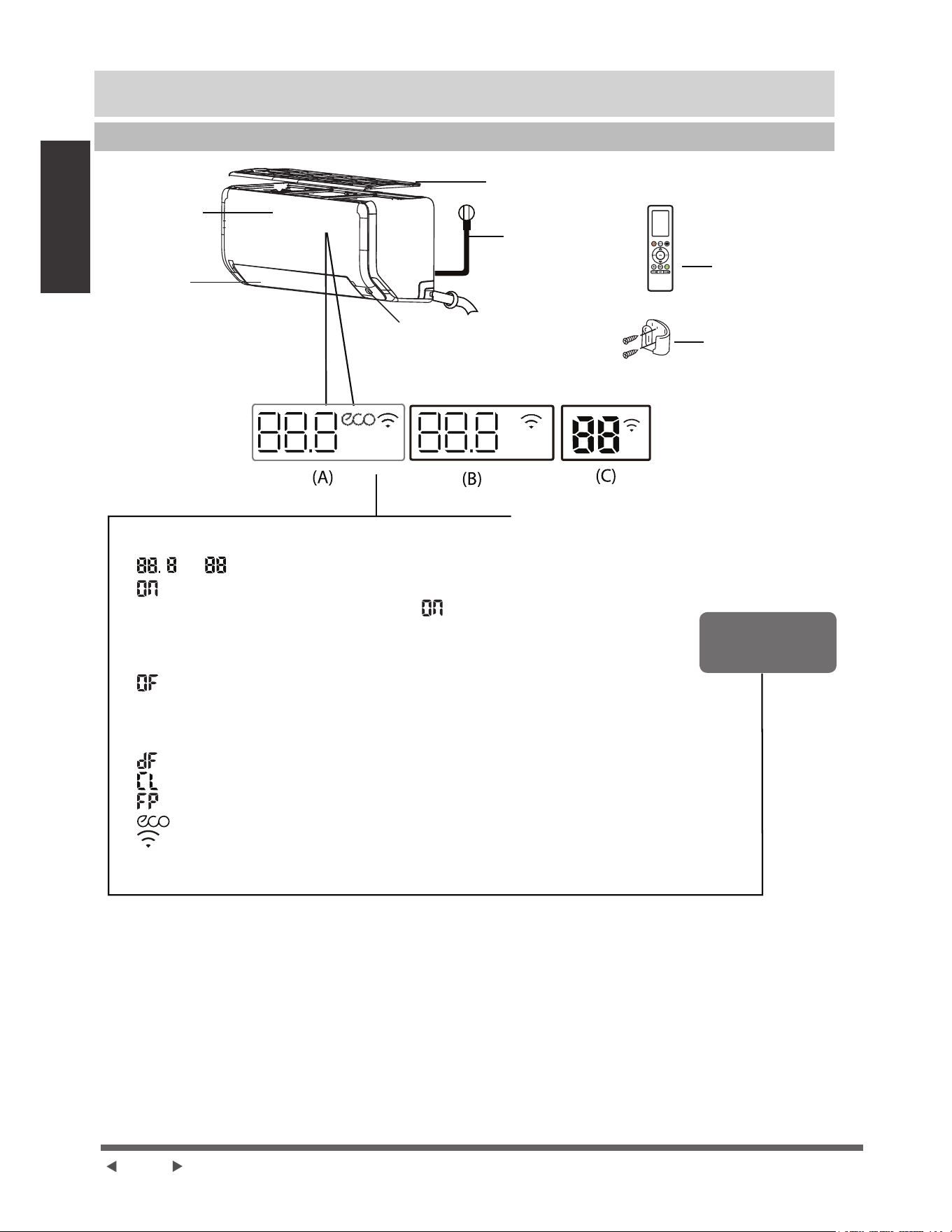
Page 8
6SpFL¿FDWLRQVHW
fonctions de l’unité
6SpFL¿FDWLRQVHWIRQFWLRQVGHO¶XQLWp
$I¿FKDJHGHO¶XQLWpLQWpULHXUH
Panneau Avant
&kEOHpOHFWULTXH
(Certains
appareils)
)LOWUHjDLU
(tirer vers le haut)
Volet
¯LOLQWHOOLJHQW(&2
(certains appareils)
Télécommande
Support de
télécommande
(certaines unités)
)HQrWUHG¶DI¿FKDJH
©
ª© ª$I¿FKHODWHPSpUDWXUHODIRQFWLRQHWOHVFRGHVG¶HUUHXU
«
ªSHQGDQWVHFRQGHVORUVTXH
Ɣ7,0(521HVWUpJOpVLO¶XQLWpHVWpWHLQW©
ªUHVWHDOOXPpTXDQG7,0(521
HVWUpJOp
Ɣ/HVIRQFWLRQV)5(6+89&ODPS6:,1*785%2(&2%5((=($:$<(&2
,17(//,*(17(<(RX6,/(1&(VRQWDFWLYpHV
©
ªSHQGDQWVHFRQGHVORUVTXH
Ɣ7,0(52))HVWUpJOp
Ɣ/HVIRQFWLRQV)5(6+89&ODPS6:,1*785%2(&2%5((=($:$<(&2
,17(//,*(17(<(RX6,/(1&(VRQWGpVDFWLYpHV
©
ªORUVGXGpJLYUDJHSRXUXQLWpVGHUHIURLGLVVHPHQWGHFKDXIIDJH
©
ªORUVTXHODIRQFWLRQGHQHWWR\DJHDFWLIHVWDFWLYpH
©
ªORUVTXHOHPRGHGHFKDXIIDJH&)HVWDFWLYpFHUWDLQHVXQLWpV
©
ªORUVTXHODIRQFWLRQ(&2HVWDFWLYpHFHUWDLQHVXQLWpV
©
ªORUVTXHODIRQFWLRQFRPPDQGHVDQV¿OHVWDFWLYpHFHUWDLQHVXQLWpV
6LJQL¿FDWLRQGX
FRGHG¶DI¿FKDJH
NOTE : 'LIIpUHQWVPRGqOHVRQWXQSDQQHDXDYDQWHWXQHIHQrWUHG¶DI¿FKDJHGLIIpUHQWV7RXVOHVLQGLFDWHXUV
GpFULWVFLGHVVRXVQHVRQWSDVGLVSRQLEOHVSRXUOHFOLPDWLVHXUTXHYRXVDYH]DFKHWp9HXLOOH]YpUL¿HUODIHQrWUH
G¶DI¿FKDJHLQWpULHXUHGHO¶XQLWpTXHYRXVDYH]DFKHWpH
/HVLOOXVWUDWLRQVGHFHPDQXHOVRQWjWLWUHH[SOLFDWLI/DIRUPHUpHOOHGHYRWUHXQLWpLQWpULHXUHSHXWrWUHOpJqUHPHQW
différente. La forme réelle prévaut.

Page 9
protection de sécurité peuvent s'activer et entraîner la désactivation de l'appareil.
Onduleur Type Split
Mode COOL mode HEAT Mode DRY
POUR LES UNITÉS
EXTÉRIEURES ÉQUIPÉES
CARTER
Lorsque la température
recommandons fortement
à tout moment pour assurer
et continue.
Température
Température
Mode COOL Mode HEAT Mode DRY
Température
Température
NOTE :
la surface du climatiseur peut attirer la condensation.
30
-22
-22
30
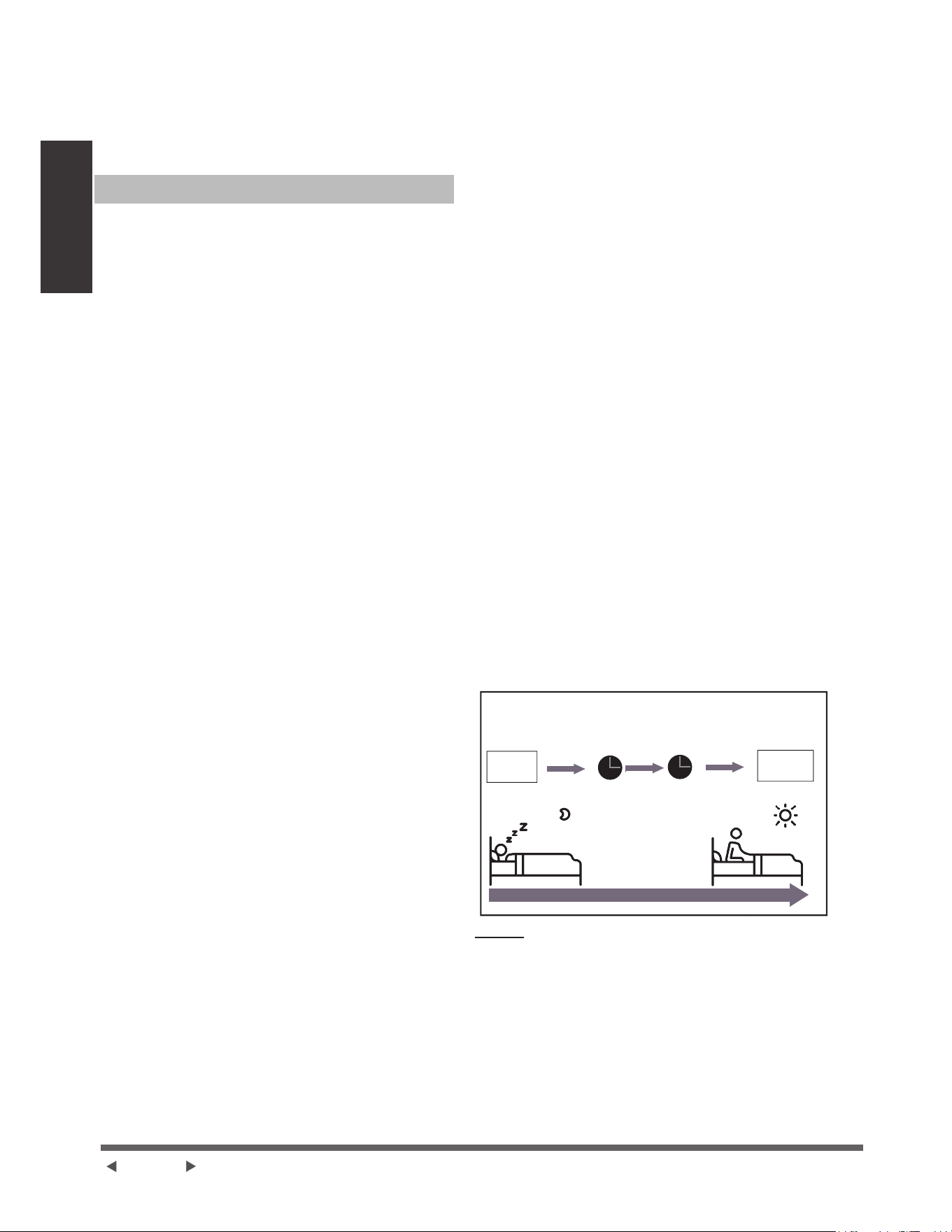
Page 10
6SpFL¿FDWLRQVHW
IRQFWLRQVGHO¶XQLWp
8QJXLGHVXUOXWLOLVDWLRQGHODWpOpFRPPDQGHLQIUDURXJH
n'est pas inclus dans cette documentation. Toutes les
IRQFWLRQVQHVRQWSDVGLVSRQLEOHVSRXUOHFOLPDWLVHXU
YHXLOOH]YpUL¿HUODI¿FKDJHLQWpULHXUHWODWpOpFRPPDQGH
de l'appareil que vous avez acheté.
$XWUHVIRQFWLRQV
Ɣ 5HGpPDUUDJHDXWRPDWLTXHFHUWDLQHVXQLWpV
6LODSSDUHLOSHUGODOLPHQWDWLRQpOHFWULTXHLO
UHGpPDUUHUDDXWRPDWLTXHPHQWDYHFOHVUpJODJHV
SUpFpGHQWVXQHIRLVODOLPHQWDWLRQHVWUpWDEOLH
Ɣ $QWLPRLVLVVXUHFHUWDLQHVXQLWpV
/RUVTXHODSSDUHLOHVWpWHLQWHQPRGH&22/
$872&22/RX'5<OHFOLPDWLVHXUFRQWLQXHGH
IRQFWLRQQHUjWUqVIDLEOHSXLVVDQFHSRXUVpFKHU
l'eau condensée et empêcher la formation de
moisissure.
Ɣ &RPPDQGHVDQV¿OFHUWDLQHVXQLWpV
/DFRPPDQGHVDQV¿OYRXVSHUPHWGHFRQWU{OHU
YRWUHFOLPDWLVHXUjODLGHGHYRWUHWpOpSKRQHPRELOH
HWGXQHFRQQH[LRQVDQV¿O
3RXUODFFqVDXGLVSRVLWLI86%OHUHPSODFHPHQW
les opérations de maintenance doivent être
effectués par du personnel professionnel.
Ɣ 0pPRLUHGDQJOHGHYROHWFHUWDLQHVXQLWpV
/RUVTXHYRXVDOOXPH]YRWUHDSSDUHLOOHYROHW
UHSUHQGDXWRPDWLTXHPHQWVRQDQFLHQDQJOH
Ɣ )RQFWLRQ1HWWR\DJHDFWLI
/DWHFKQRORJLH1HWWR\DJHDFWLIGpJDJHODSRXVVLqUH
ODPRLVLVVXUHHWODJUDLVVHTXLSHXYHQWFDXVHUGHV
RGHXUVORUVTXHOOHDGKqUHjOpFKDQJHXUGHFKDOHXU
HQFRQJHODQWDXWRPDWLTXHPHQWSXLVHQGpJHODQW
UDSLGHPHQWOHJLYUH8QVRQ©SLSLªVHUDHQWHQGX
/RSpUDWLRQ1HWWR\DJHDFWLIHVWXWLOLVpHSRXU
SURGXLUHSOXVGHDXFRQGHQVpHD¿QGDPpOLRUHU
OHIIHWGHQHWWR\DJHHWODLUIURLGVHUDH[SXOVp
$SUqVOHQHWWR\DJHODURXHjYHQWLQWHUQHFRQWLQXH
à fonctionner avec l’air chaud pour sécher
OpYDSRUDWHXUHPSrFKDQWDLQVLODFURLVVDQFHGHOD
PRLVLVVXUHHWJDUGDQWOLQWpULHXUSURSUH
/RUVTXHFHWWHIRQFWLRQHVWDFWLYpHODIHQrWUH
GDI¿FKDJHGHOXQLWpLQWpULHXUHDSSDUDvW©
&/ªDSUqVjPLQXWHVOXQLWpVpWHLQW
DXWRPDWLTXHPHQWHWDQQXOHODIRQFWLRQ1HWWR\DJH
actif.
Ɣ %ULVHpORLJQpHFHUWDLQHVXQLWpV
&HWWHIRQFWLRQpYLWHTXHODLUQHVRXIÀHGLUHFWHPHQW
VXUOHFRUSVHWYRXVIDLWHVH[SRVHUjODIUDvFKHXU
soyeuse.
Ɣ 'pWHFWLRQGHIXLWHGHUpIULJpUDQWFHUWDLQHV
XQLWpV
/DSSDUHLOLQWpULHXUHDI¿FKHDXWRPDWLTXHPHQW
©(/&ªORUVTXHODSSDUHLOGpWHFWHXQHIXLWHGH
UpIULJpUDQW
Ɣ ¯LOLQWHOOLJHQW(&2FHUWDLQVXQLWpV
/HV\VWqPHHVWFRQWU{OpLQWHOOLJHPPHQWHQIRQFWLRQ
G°LOLQWHOOLJHQW,OSHXWGpWHFWHUOHVDFWLYLWpV
GHVSHUVRQQHVGDQVODFKDPEUH(QPRGH
UHIURLGLVVHPHQWORUVTXHYRXVrWHVDEVHQWSHQGDQW
PLQXWHVO¶DSSDUHLOUpGXLWDXWRPDWLTXHPHQW
ODIUpTXHQFHSRXUpFRQRPLVHUGHO¶pQHUJLH
XQLTXHPHQWSRXUOHVPRGqOHVjRQGXOHXU(W
l'unité démarrera et reprendra automatiquement
son fonctionnement si elle détecte à nouveau une
activité humaine.
Ɣ )RQFWLRQQHPHQWGHVRPPHLO
/DIRQFWLRQ6/((3HVWXWLOLVpHSRXUGLPLQXHUOD
FRQVRPPDWLRQGpQHUJLHSHQGDQWOHVRPPHLOHWQH
QpFHVVLWHSDVOHVPrPHVUpJODJHVGHWHPSpUDWXUH
SRXUUHVWHUFRQIRUWDEOH&HWWHIRQFWLRQQHSHXWrWUH
activée que par la télécommande. Et la fonction
6/((3QHVWSDVGLVSRQLEOHHQPRGH)$1RX'5<
(QPRGH&22/ODSSDUHLODXJPHQWHOD
WHPSpUDWXUHGH&)DSUqVKHXUHHW
DXJPHQWHGH&)VXSSOpPHQWDLUHDSUqVXQH
autre heure.
(QPRGH+($7ODSSDUHLOGLPLQXHODWHPSpUDWXUH
GH&)DSUqVKHXUHHWGLPLQXHGH&)
VXSSOpPHQWDLUHDSUqVXQHDXWUHKHXUH
/DIRQFWLRQVRPPHLOV¶DUUrWHDSUqVKHXUHVHWOH
V\VWqPHFRQWLQXHGHIRQFWLRQQHUDYHFODVLWXDWLRQ
¿QDOH
)RQFWLRQQHPHQW6/((3
%DVVHFRQVRPPDWLRQG¶pQHUJLHHQPRGH6/((3
5pJOHUOD
température
Continuer à
fonctionner
0RGH&22/&)SDUKHXUH
SHQGDQWOHVGHX[SUHPLqUHVKHXUHV
1h 1h
0RGH+($7&)SDUKHXUH
SHQGDQWOHVGHX[SUHPLqUHVKHXUHV
NOTE :
3RXUOHVFOLPDWLVHXUVW\SHPXOWLVSOLWOHVIRQFWLRQV
VXLYDQWHVQHVRQWSDVGLVSRQLEOHV
)RQFWLRQGHQHWWR\DJHDFWLIIRQFWLRQ6,/(1&(IRQFWLRQ
%5((=($:$<IRQFWLRQGHGpWHFWLRQGHVIXLWHVGH
UpIULJpUDQWHWIRQFWLRQ(FR
FHUWDLQHVXQLWpV
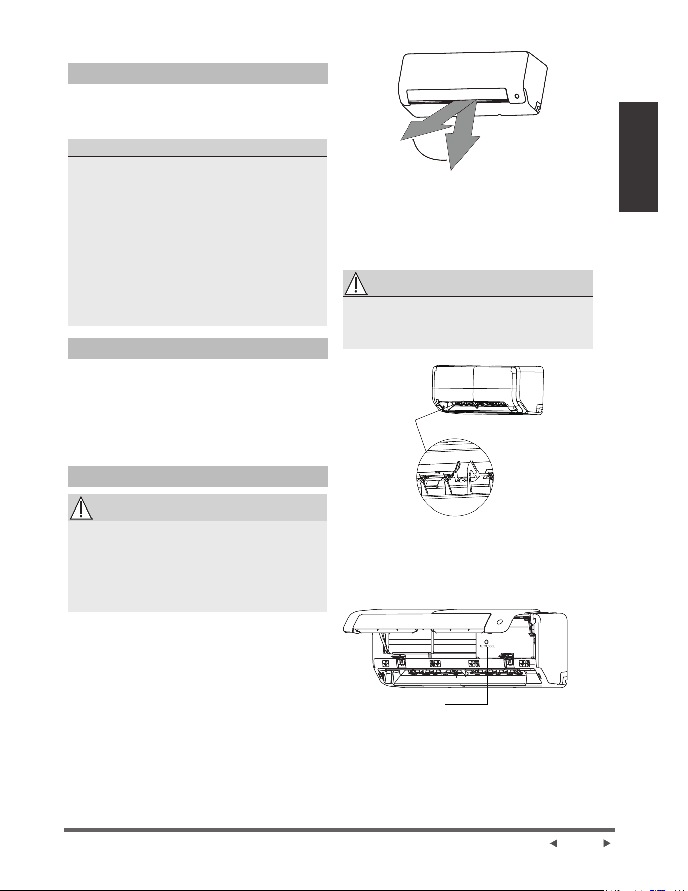
Page 11
6SpFL¿FDWLRQVHW
fonctions de l’unité
Ɣ 5pJODJHGHO¶DQJOHGXÀX[G¶DLU
Réglage
GHODQJOHYHUWLFDOGXÀX[GDLU
/RUVTXHODSSDUHLOHVWDOOXPpXWLOLVH]OHERXWRQ
%$/$<$*(SRXUUpJOHUODGLUHFWLRQO¶DQJOH
YHUWLFDOGXÀX[GDLU9HXLOOH]UHSRUWHUDX0DQXHOGH
Télécommande pour plus de détails.
NOTE SUR LES ANGLES DE VOLET
/RUVTXHYRXVXWLOLVH]OHPRGH&22/RX'5<QHSDV
UpJOHUOHYROHWjXQDQJOHWURSYHUWLFDOSHQGDQWXQH
ORQJXHSpULRGH&HODSHXWSURYRTXHUODFRQGHQVDWLRQ
GHO¶HDXVXUODODPHGHYROHWTXLWRPEHUDVXUYRWUH
SODQFKHURXYRVPHXEOHV
/RUVTXHYRXVXWLOLVH]OHPRGH&22/RX+($7OH
UpJODJHGXYROHWjXQDQJOHWURSYHUWLFDOSHXWUpGXLUH
OHVSHUIRUPDQFHVGHO¶XQLWpHQUDLVRQG¶XQGpELWG¶DLU
restreint.
NOTE :&RQIRUPpPHQWDX[H[LJHQFHVGHVQRUPHV
HQYLJXHXUYHXLOOH]UpJOHUOHYROHWGHFLUFXODWLRQ
GDLUYHUWLFDOVXUVRQDQJOHPD[LPDOORUVGXWHVWGH
FDSDFLWpGHFKDXIIDJH
5pJODJHGHO¶DQJOHKRUL]RQWDOGXÀX[G¶DLU
/¶DQJOHKRUL]RQWDOGXÀX[G¶DLUGRLWrWUHUpJOp
PDQXHOOHPHQW3LQFH]ODWLJHGHGpÀHFWHXUYRLUOD
¿JXUH%HWDMXVWHUODPDQXHOOHPHQWGDQVODGLUHFWLRQ
souhaitée.
Pour certaines unitésO¶DQJOHKRUL]RQWDOGXÀX[
G¶DLUSHXWrWUHUpJOpSDUODWpOpFRPPDQGH9
HXLOOH]VH
référer au Manuel de Télécommande.
)RQFWLRQQHPHQWPDQXHOVDQVWpOpFRPPDQGH
ATTENTION
/HERXWRQPDQXHOHVWGHVWLQpjGHV¿QVGHWHVWHW
GHO¶RSpUDWLRQG¶XUJHQFHXQLTXHPHQW1HSDVXWLOLVHU
cette fonction à moins que la télécommande soit
SHUGXHHWF¶HVWDEVROXPHQWQpFHVVDLUH8WLOLVH]
ODWpOpFRPPDQGHjDFWLYHUO¶XQLWpSRXUUpWDEOLUOH
IRQFWLRQQHPHQWQRUPDO/¶XQLWpGRLWrWUHpWHLQWHDYDQW
le fonctionnement manuel.
3RXUIDLUHIRQFWLRQQHUYRWUHXQLWpPDQXHOOHPHQW
1. Localisez le bouton 0$18$/&21752/ sur le
F{WpGURLWGHODSSDUHLO
2. Appuyez une fois sur le bouton MANUAL
&21752/SRXUDFWLYHUOHPRGH)25&('$872
3. Appuyez à nouveau sur le bouton MANUAL
&21752/SRXUDFWLYHUOHPRGH)25&('
&22/,1*
4. $SSX\H]XQHWURLVLqPHIRLVVXUOHERXWRQ0$18$/
&21752/SRXUpWHLQGUHOXQLWp
Plage
NOTE : Ne pas déplacer le volet à la main. Cela
entraînera la désynchronisation du volet. Si cela
VHSURGXLWYHXLOOH]pWHLQGUHO¶XQLWpHWOHGpEUDQFKHU
SHQGDQWTXHOTXHVVHFRQGHVSXLVUHGpPDUUHUO¶XQLWp
Cela réinitialisera le volet.
)LJ$
ATTENTION
1HSDVSODFHUYRVGRLJWVGDQVRXSUqVGHOD
VRXIÀHULHHWGXF{WpG¶DVSLUDWLRQGHO¶XQLWp/H
YHQWLODWHXUjJUDQGHYLWHVVHjOLQWpULHXUGHOXQLWp
SHXWFDXVHUGHVEOHVVXUHV
7LJHGH
GpÀHFWHXU
)LJ%
Bouton de
commande manuelle
)LJ&
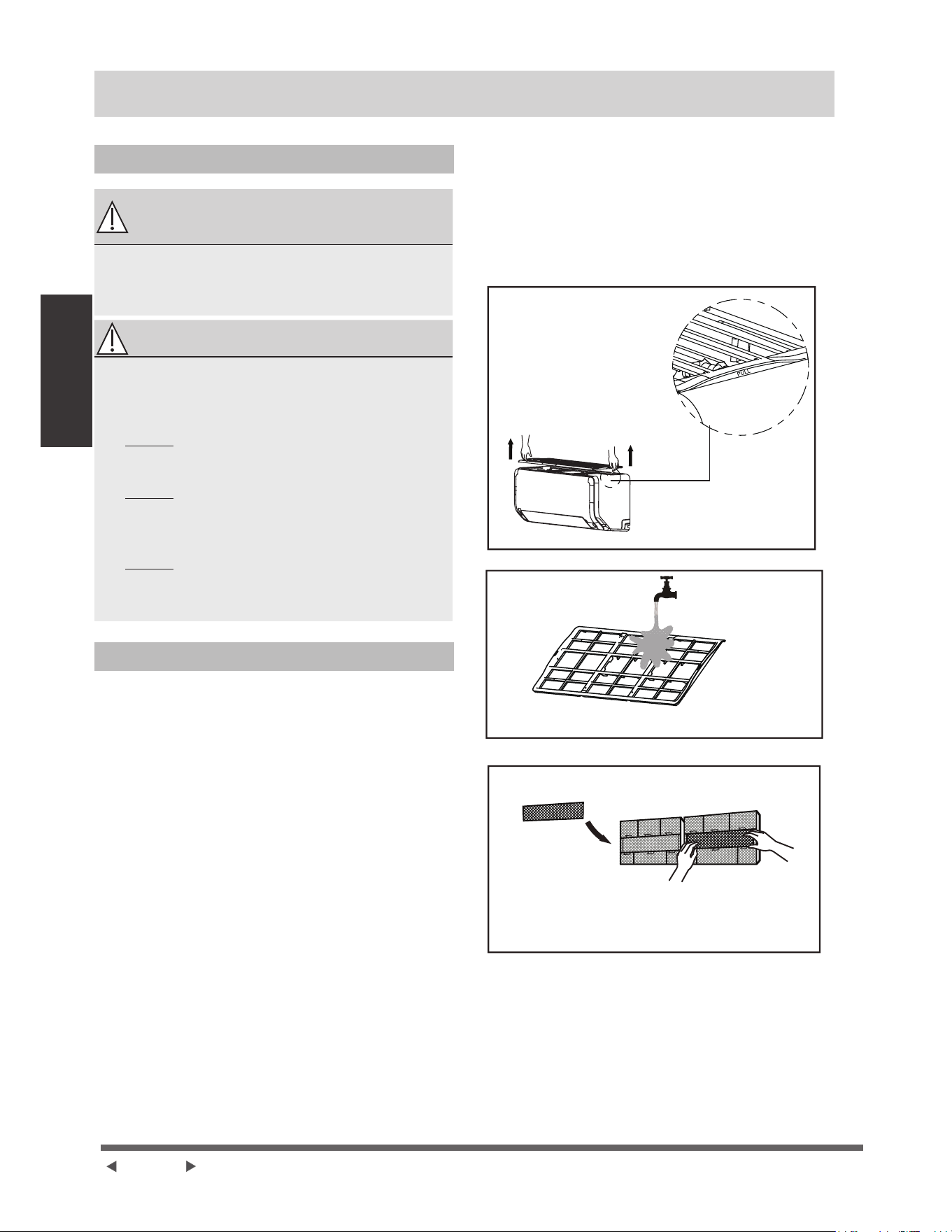
Page 12
Entretien et
maintenance
Entretien et maintenance
Nettoyage de l'unité intérieure
$9$171(772<$*( OU
MAINTENANCE
e7(,*1(=728-28569275(6<67Ê0(
'(&/,0$7,6$7,21(7'e%5$1&+(=621
ALIMENTATION ÉLECTRIQUE AVANT TOUT
1(772<$*(28(175(7,(1
ATTENTION
8WLOLVH]XQLTXHPHQWXQFKLIIRQGRX[HWVHFSRXU
HVVX\HUODSSDUHLO6LODSSDUHLOHVWWURSVDOHYRXV
SRXYH]XWLOLVHUXQFKLIIRQLPELEpGHDXWLqGHSRXU
l'essuyer.
Ɣ Ne pas utiliser des produits chimiques ou des
chiffons traités chimiquement pour nettoyer
l'appareil.
Ɣ Ne pasXWLOLVHUGXEHQ]qQHGXGLOXDQWjSHLQWXUH
de la poudre à polir ou d'autres solvants pour
nettoyer l’appareil. Ils peuvent faire craquer ou
déformer la surface en plastique.
Ɣ Ne pasXWLOLVHUGHOHDXGHSOXVGH&)
pour nettoyer le panneau avant. Cela peut
provoquer la déformation ou la décoloration du
panneau.
Nettoyage GHYRWUH¿OWUHjDLU
8Q¿OWUHjDLUERXFKpSHXWUpGXLUHOHI¿FDFLWpGX
UHIURLGLVVHPHQWGHYRWUHDSSDUHLOSHXWpJDOHPHQW
UHQGUHOHÀX[GDLULUUpJXOLHUHWWURSEUX\DQWDORUV
YHXLOOH]QHWWR\HUOH¿OWUHjDLUDXVVLVRXYHQWTXH
QpFHVVDLUH'qVTXHYRXVHQWHQGH]OHEUXLWDQRUPDO
GXÀX[GDLUYHXLOOH]QHWWR\HULPPpGLDWHPHQWOH¿OWUHj
air.
1. /H¿OWUHjDLUVHWURXYHVXUOHKDXWGXFOLPDWLVHXU
2. 7HQH]OHVGHX[F{WpVGX¿OWUHVXSpULHXUjOHQGURLW
PDUTXp©38//ªSXLVWLUH]OHYHUVOHKDXW
3. 6LYRWUH¿OWUHHVWGRWpGHVSHWLWV¿OWUHV
G¶DVVDLQLVVHPHQWGHO¶DLUYHXLOOH]OHVGpJDJHU
GX¿OWUHSOXVJUDQG1HWWR\H]FHV¿OWUHVGH
rafraîchissement de l'air avec un aspirateur à main.
4. 1HWWR\H]OHJUDQG¿OWUHGDLUDYHFGHOHDXFKDXGH
HWVDYRQQHXVH9HLOOH]jXWLOLVHUXQGpWHUJHQWGRX[
5. 5LQFH]OH¿OWUHjOHDXGRXFHSXLVVHFRXH]OH[FqV
d'eau.
6. )DLWHVOHVpFKHUGDQVXQHQGURLWIUDLVHWVHFHW
pYLWH]GHOH[SRVHUjODOXPLqUHGLUHFWHGXVROHLO
7. $SUqVODGpVKXPLGL¿FDWLRQUHPRQWH]OH¿OWUH
GDVVDLQLVVHPHQWGHODLUVXUOH¿OWUHSOXVJUDQG
SXLVUpLQVWDOOH]OHVXUOXQLWpLQWpULHXUH
5HWLUH]OH¿OWUHGHGpVRGRULVDWLRQjODUULqUHGX
¿OWUHSOXVJUDQGFHUWDLQHVXQLWpVQHWWR\H]OH
avec un aspirateur à main.
7HQH]OHVGHX[F{WpVGX¿OWUH
supérieur à l'endroit marqué
©38//ªSXLVWLUH]OHYHUV
le haut.
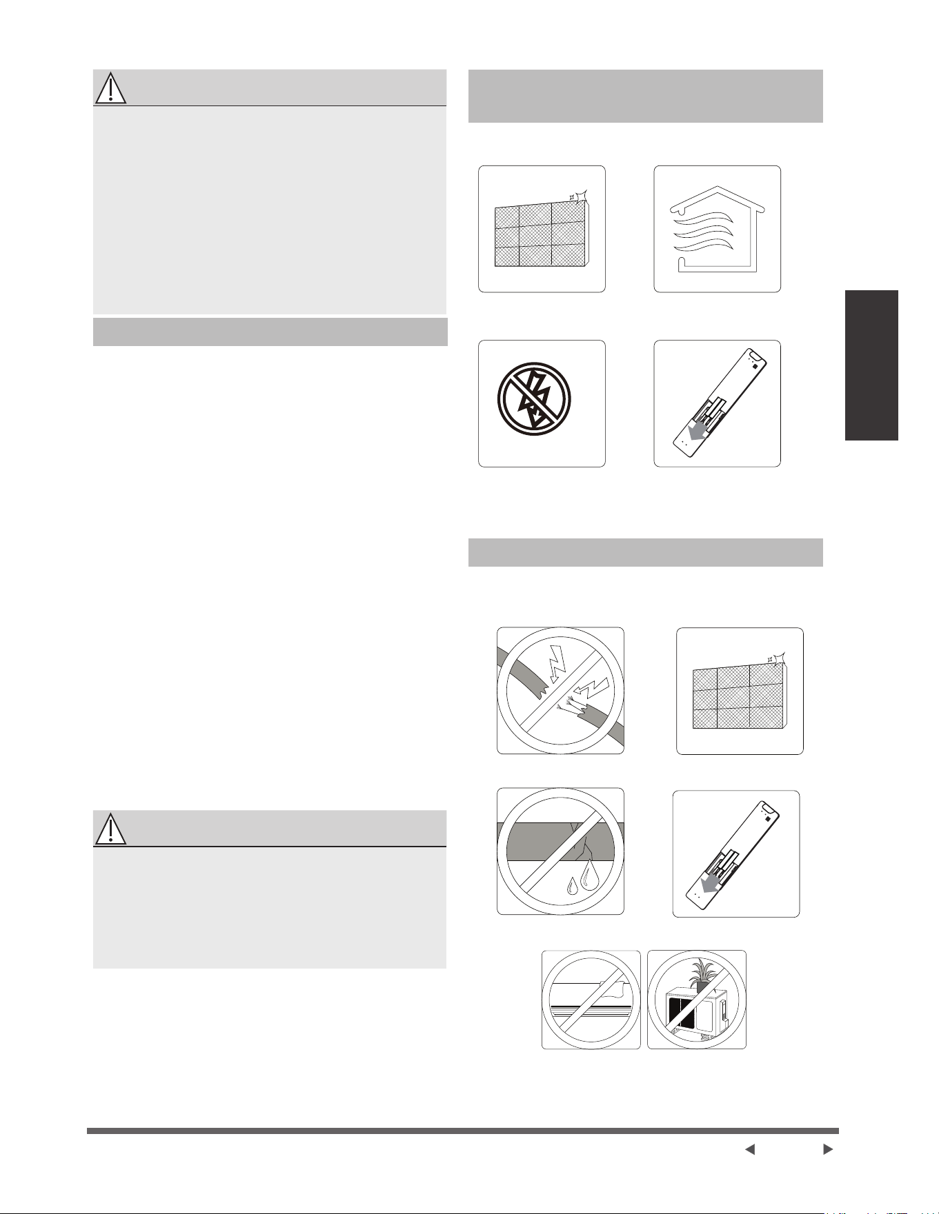
Page 13
Entretien et
maintenance
ATTENTION
Ɣ $YDQWGHFKDQJHUOH¿OWUHRXGHQHWWR\HUpWHLJQH]
ODSSDUHLOHWGpEUDQFKH]VRQDOLPHQWDWLRQ
électrique.
Ɣ /RUVGXUHWUDLWGX¿OWUHQHSDVWRXFKHUOHVSDUWLHV
PpWDOOLTXHVGHODSSDUHLO/HVERUGVPpWDOOLTXHV
tranchants peuvent vous couper.
Ɣ 1HSDVXWLOLVHUOHDXSRXUQHWWR\HUOLQWpULHXUGH
l'appareil intérieure. Cela peut détruire l'isolation
et provoquer un choc électrique.
Ɣ 1HSDVH[SRVHUOH¿OWUHjODOXPLqUHGLUHFWHGX
VROHLOORUVGHODGpVKXPLGL¿FDWLRQG¶DLU&HODSHXW
GpWUXLUHOH¿OWUH
5DSSHOVGH¿OWUHjDLU RSWLRQQHO
5DSSHOGHQHWWR\DJHGH¿OWUHjDLU
$SUqVKHXUHVG¶XWLOLVDWLRQODIHQrWUHG¶DI¿FKDJHGH
O¶XQLWpLQWpULHXUHFOLJQRWHHQLQGLTXDQW©&/ª&HFLHVW
XQUDSSHOSRXUYRXVUDSSHOHUGHQHWWR\HUYRWUH¿OWUH
$SUqVVHFRQGHVO¶DSSDUHLOUHYLHQGUDjVRQDI¿FKDJH
précédent.
3RXUUpLQLWLDOLVHUOHUDSSHODSSX\H]IRLVVXUOHERXWRQ
LED de votre télécommande ou appuyer 3 fois sur le
ERXWRQMANUAL CONTROL 6LYRXVQHUpLQLWLDOLVH]
SDVOHUDSSHOO¶LQGLFDWHXU©&/ªFOLJQRWHUDjQRXYHDX
lorsque vous redémarrez l’appareil.
5DSSHOVXUOHUHPSODFHPHQWGX¿OWUHjDLU
$SUqVKHXUHVG¶XWLOLVDWLRQODIHQrWUHG¶DI¿FKDJH
GHO¶XQLWpLQWpULHXUHFOLJQRWHHQLQGLTXDQW©Q)ª&HFL
est un rappel pour vous rappeler de remplacer votre
¿OWUH$SUqVVHFRQGHVO¶DSSDUHLOUHYLHQGUDjVRQ
DI¿FKDJHSUpFpGHQW
3RXUUpLQLWLDOLVHUOHUDSSHODSSX\HUIRLVVXUOHERXWRQ
LED de votre télécommande ou appuyer 3 fois sur le
ERXWRQMANUAL CONTROL6LYRXVQHUpLQLWLDOLVH]
SDVOHUDSSHOO¶LQGLFDWHXU©Q)ªFOLJQRWHUDjQRXYHDX
lorsque vous redémarrez l’appareil.
ATTENTION
Ɣ 7RXWHRSpUDWLRQGHPDLQWHQDQFHHWGHQHWWR\DJH
GHOXQLWpH[WpULHXUHGRLWrWUHHIIHFWXpHSDUXQ
UHYHQGHXUDJUppRXXQIRXUQLVVHXUGHVHUYLFHV
DJUpp
Ɣ Toute réparation de l'appareil doit être effectuée
SDUXQUHYHQGHXUDJUppRXXQIRXUQLVVHXUGH
VHUYLFHVDJUpp
Maintenance - Longues périodes de
non-utilisation
6LYRXVSUpYR\H]GHQHSDVXWLOLVHUYRWUHFOLPDWLVHXU
SHQGDQWXQHSpULRGHSURORQJpHSURFpGH]FRPPHVXLW
1HWWR\H]WRXVOHV¿OWUHV
eWHLJQH]ODSSDUHLO
HWGpEUDQFKH]
l'alimentation
$FWLYH]ODIRQFWLRQ
9(17,/$7,21MXVTXjFHTXH
ODSSDUHLOVqFKHFRPSOqWHPHQW
(QOHYH]OHVEDWWHULHVGHOD
télécommande
Maintenance – Inspection pré-saison
$SUqVGHORQJXHVSpULRGHVGHQRQXWLOLVDWLRQRXDYDQW
GHVSpULRGHVGXWLOLVDWLRQIUpTXHQWHYHXLOOH]IDLUHFHTXL
VXLW
9pUL¿H]OHV¿OV
HQGRPPDJpV
9pUL¿H]OHVIXLWHV
1HWWR\H]WRXVOHV¿OWUHV
5HPSODFH]OHVEDWWHULHV
$VVXUH]YRXVTXHULHQQHEORTXHWRXWHVOHV
entrées et sorties d'air

Page 14
Dépannage
Dépannage
&216,*1(6'(6e&85,7e
6LYRXVUHQFRQWUH]81(GHVFRQGLWLRQVVXLYDQWHVpWHLQGUHYRWUHDSSDUHLOLPPpGLDWHPHQW
Ɣ /HFkEOHGDOLPHQWDWLRQHVWHQGRPPDJpRXDQRUPDOHPHQWFKDXG
Ɣ 9RXVVHQWH]XQHRGHXUGHEUOp
Ɣ /DSSDUHLOpPHWGHVRQVIRUWVRXDQRUPDX[
Ɣ 8QIXVLEOHGDOLPHQWDWLRQVHGpFOHQFKHRXOHGLVMRQFWHXUVHGpFOHQFKHIUpTXHPPHQW
Ɣ 'HOHDXRXGDXWUHVREMHWVWRPEHQWGDQVRXKRUVGHODSSDUHLO
NE PAS ESSAYER DE LE RÉPARER PAR VOUS-MÊME ! CONTACTER UN
)2851,66(85'(6(59,&(6$8725,6e,00e',$7(0(17
Problèmes courants
/HVSUREOqPHVVXLYDQWVQHFRQVWLWXHQWSDVXQG\VIRQFWLRQQHPHQWHWGDQVODSOXSDUWGHVFDVQHQpFHVVLWHQW
aucune réparation.
Problème Causes possibles
L'appareil ne s'allume
pas lorsque vous
DSSX\H]VXUOHERXWRQ
0$5&+($55Ç7
L'appareil a une fonction de protection de 3 minutes laquelle empêche l'appareil de
VXUFKDUJHU/¶DSSDUHLOQHSHXWSDVrWUHUHGpPDUUpGDQVOHVWURLVPLQXWHVVXLYDQWOD
mise en arrêt.
L'appareil passe du
PRGH)52,'&+$8'
au mode VENTILATION
/DSSDUHLOSHXWFKDQJHUVRQUpJODJHSRXUHPSrFKHUODIRUPDWLRQGHJHOVXU
ODSSDUHLO8QHIRLVODWHPSpUDWXUHHVWDXJPHQWpHODSSDUHLOUHFRPPHQFHUDj
fonctionner dans le mode précédemment sélectionné.
/DWHPSpUDWXUHUpJOpHDpWpDWWHLQWHjSDUWLUGHODTXHOOHODSSDUHLOpWHLQWOH
FRPSUHVVHXU/DSSDUHLOFRQWLQXHUDjIRQFWLRQQHUORUVTXHODWHPSpUDWXUHÀXFWXHUD
à nouveau.
L'unité intérieure émet
XQHEUXPHEODQFKH
'DQVOHVUpJLRQVKXPLGHVXQHJUDQGHGLIIpUHQFHGHWHPSpUDWXUHHQWUHODLUGDQVOD
SLqFHHWO¶DLUFRQGHQVpSHXWSURYRTXHUXQHEUXPHEODQFKH
Les unités intérieures
et extérieures émettent
XQHEUXPHEODQFKH
/RUVTXHODSSDUHLOUHGpPDUUHHQPRGH&+$8'DSUqVOHGpJLYUDJHXQHEUXPH
EODQFKHSHXWrWUHpPLVHHQUDLVRQGHOKXPLGLWpJpQpUpHSDUOHSURFHVVXVGH
GpJLYUDJH
/¶XQLWpLQWpULHXUHIDLWGX
bruit
8QEUXLWGDLUEUX\DQWSHXWVHSURGXLUHORUVTXHOHYROHWUHGp¿QLWVDSRVLWLRQ
8QEUXLWGHJULQFHPHQWSHXWVHSURGXLUHDSUqVDYRLUIDLWIRQFWLRQQHUODSSDUHLOHQ
PRGH&+$8'HQUDLVRQGHOH[SDQVLRQHWGHODFRQWUDFWLRQGHVSLqFHVHQSODVWLTXH
de l'appareil.
L'unité intérieure et
OXQLWpH[WpULHXUHIRQWGX
bruit
)DLEOHVLIÀHPHQWSHQGDQWOHIRQFWLRQQHPHQW,OHVWQRUPDOHWHVWFDXVpSDUOHJD]
UpIULJpUDQWFLUFXODQWGDQVOHVXQLWpVLQWpULHXUHHWH[WpULHXUH
)DLEOHVLIÀHPHQWORUVTXHOHV\VWqPHGpPDUUHRXORUVGDUUrWHUGHIRQFWLRQQHURX
GHGpJLYUHU&HEUXLWHVWQRUPDOHWSURYRTXpSDUODUUrWGXJD]UpIULJpUDQWRXOH
FKDQJHPHQWGHGLUHFWLRQ
%UXLWGHJULQFHPHQW/H[SDQVLRQHWODFRQWUDFWLRQQRUPDOHVGHVSLqFHVHQ
SODVWLTXHHWHQPpWDOFDXVpHVSDUGHVFKDQJHPHQWVGHWHPSpUDWXUHSHQGDQWOH
IRQFWLRQQHPHQWSHXYHQWSURYRTXHUGHVJULQFHPHQWV

Page 15
Dépannage
Problème Causes possibles
/XQLWpH[WpULHXUHIDLWGX
bruit
L'appareil fera des sons différents en fonction de son mode de fonctionnement actuel.
La poussière est émise
par l'unité intérieure ou
extérieure
/DSSDUHLOSHXWDFFXPXOHUGHODSRXVVLqUHSHQGDQWGHORQJXHVSpULRGHVGHQRQXWLOLVDWLRQHW
FHOOHFLVHUDpPLVHORUVTXHODSSDUHLOHVWDOOXPp&HODSHXWrWUHDWWpQXpHQFRXYUDQWODSSDUHLO
SHQGDQWGHORQJXHVSpULRGHVGLQDFWLYLWp
L'appareil émet une
mauvaise odeur
/DSSDUHLOSHXWDEVRUEHUOHVRGHXUVGHOHQYLURQQHPHQWOHVPHXEOHVODFXLVLQHOHV
FLJDUHWWHVHWFOHVTXHOOHVVHURQWpPLVHVSHQGDQWOHIRQFWLRQQHPHQW
/HV¿OWUHVGHODSSDUHLOVRQWPRLVLVHWGRLYHQWrWUHQHWWR\pV
Le ventilateur de l'unité
H[WpULHXUHQHIRQFWLRQQHSDV
3HQGDQWOHIRQFWLRQQHPHQWODYLWHVVHGXYHQWLODWHXUHVWFRQWU{OpHSRXURSWLPLVHUOH
fonctionnement du produit.
/HIRQFWLRQQHPHQWHVW
HUUDWLTXHLPSUpYLVLEOHRX
l'appareil ne répond pas
/HVLQWHUIpUHQFHVSURYHQDQWGHVWRXUVGHWpOpSKRQHSRUWDEOHHWGHVERRVWHUVjGLVWDQFH
peuvent provoquer un dysfonctionnement de l'appareil.
'DQVFHFDVHVVD\HUFHTXLVXLW
Ɣ 'pEUDQFKHUODOLPHQWDWLRQSXLVUHFRQQHFWHU
Ɣ $SSX\HUVXUOHERXWRQ0$5&+($55Ç7GHODWpOpFRPPDQGHSRXUUHGpPDUUHUOH
fonctionnement.
NOTE : 6LOHSUREOqPHSHUVLVWHFRQWDFWHUXQUHYHQGHXUORFDORXOHFHQWUHGHVHUYLFHFOLHQWqOHOHSOXVSURFKH/HV
UDSSRUWHUDYHFXQHGHVFULSWLRQGpWDLOOpHGXG\VIRQFWLRQQHPHQWGHODSSDUHLODLQVLTXHYRWUHQXPpURGHPRGqOH
Dépannage
(QFDVGHSUREOqPHYHXLOOH]YpUL¿HUOHVSRLQWVVXLYDQWVDYDQWGHFRQWDFWHUXQHHQWUHSULVHGHUpSDUDWLRQ
Problème Causes possibles Solution
0DXYDLVHSHUIRUPDQFHGH
UHIURLGLVVHPHQW
/DFRQ¿JXUDWLRQGHODWHPSpUDWXUHSHXWrWUH
VXSpULHXUHjODWHPSpUDWXUHDPELDQWH
$EDLVVHUOHUpJODJHGHODWHPSpUDWXUH
/pFKDQJHXUGHFKDOHXUGHOXQLWpLQWpULHXUH
RXH[WpULHXUHHVWVDOH
1HWWR\HUOpFKDQJHXUGHFKDOHXUFRQFHUQp
/H¿OWUHjDLUHVWVDOH 5HWLUHUOH¿OWUHHWOHQHWWR\HUFRQIRUPpPHQW
DX[LQVWUXFWLRQV
L'entrée ou la sortie d'air de l'un ou l'autre
DSSDUHLOHVWEORTXp
eWHLQGUHODSSDUHLOHQOHYHUOREVWUXFWLRQHWOD
rallumer
Les portes et les fenêtres sont ouvertes $VVXUHUTXHWRXWHVOHVSRUWHVHWIHQrWUHV
soient fermées pendant le fonctionnement
de l'appareil
/DFKDOHXUH[FHVVLYHHVWJpQpUpHSDUOD
OXPLqUHGXVROHLO
)HUPHUOHVIHQrWUHVHWOHVULGHDX[SHQGDQW
les périodes de forte chaleur ou de soleil
7URSGHVRXUFHVGHFKDOHXUGDQVODSLqFHOHV
SHUVRQQHVOHVRUGLQDWHXUVOHVDSSDUHLOV
pOHFWURQLTXHVHWF
Réduire la quantité de sources de chaleur
)DLEOHUpIULJpUDQWGjXQHIXLWHRXjXQH
XWLOLVDWLRQjORQJWHUPH
9pUL¿HUVLO\DGHVIXLWHVUHIHUPHUVL
QpFHVVDLUHHWDMRXWHUGXUpIULJpUDQW
/DIRQFWLRQ6,/(1&(HVWDFWLYpHIRQFWLRQ
RSWLRQQHOOH
/DIRQFWLRQ6,/(1&(SHXWUpGXLUHOHV
performances du produit en réduisant la
fréquence de fonctionnement. Désactiver la
IRQFWLRQ6,/(1&(
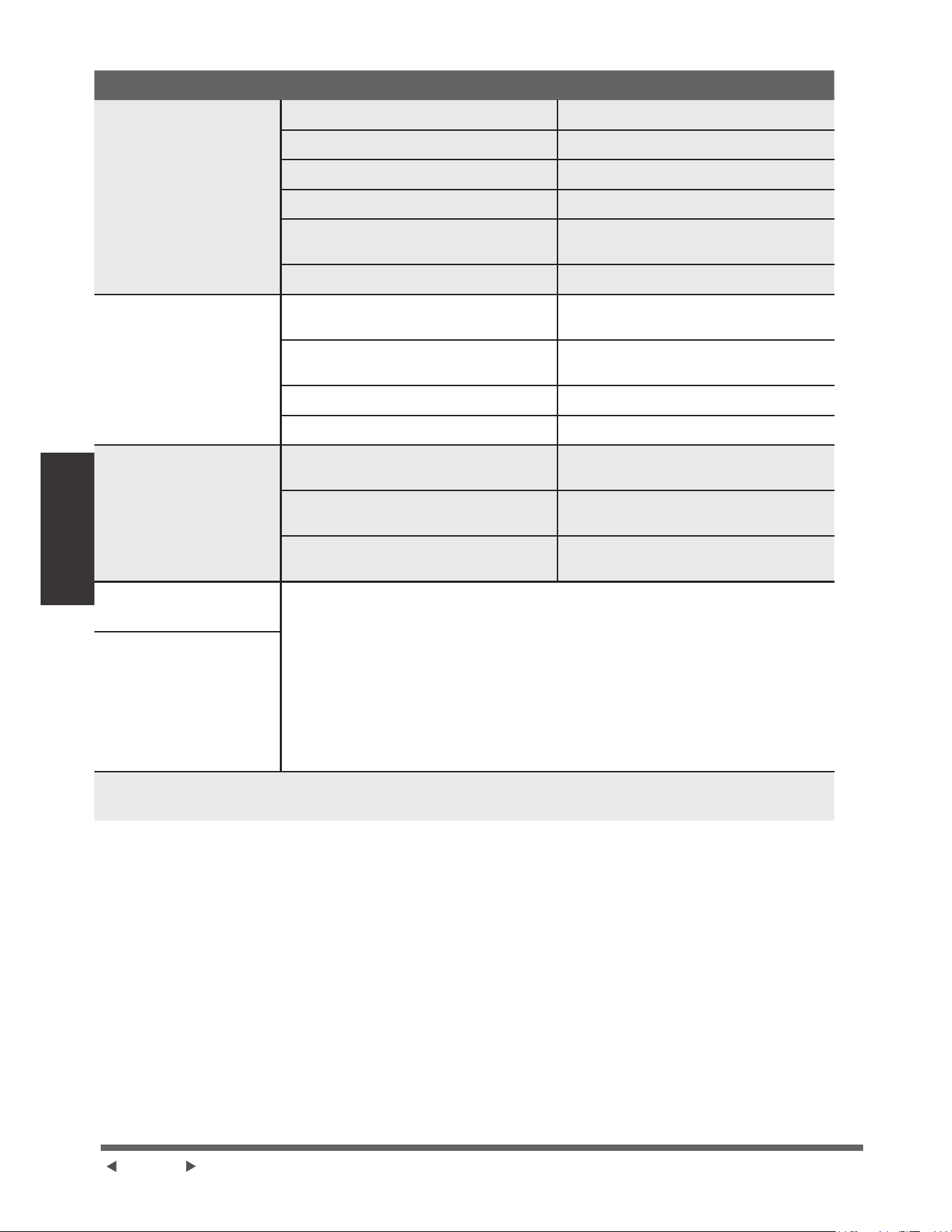
Page 16
Dépannage
Problème Causes possibles Solution
/DSSDUHLOQHIRQFWLRQQH
pas
Panne de courant $WWHQGUHTXHODOLPHQWDWLRQVRLWUpWDEOLH
L'alimentation est coupée $OOXPHUODSSDUHLO
/HIXVLEOHHVWVDXWp 5HPSODFHUOHIXVLEOH
/HVEDWWHULHVGHODWpOpFRPPDQGHVpSXLVHQW 5HPSODFHUOHVEDWWHULHV
La protection de 3 minutes de l'appareil a
été activée
$WWHQGUHWURLVPLQXWHVDSUqVOHUHGpPDUUDJH
de l'appareil
La minuterie est activée Désactiver la minuterie
L'appareil se démarre et
VDUUrWHIUpTXHPPHQW
,O\DWURSRXSHXGHUpIULJpUDQWGDQVOH
V\VWqPH
9pUL¿HUOHVIXLWHVHWUHFKDUJHUOHV\VWqPH
DYHFGXUpIULJpUDQW
'XJD]RXGHOKXPLGLWpLQFRPSUHVVLEOHHVW
HQWUpGDQVOHV\VWqPH
eYDFXHUHWUHFKDUJHUOHV\VWqPHDYHFGX
UpIULJpUDQW
Le compresseur est cassé Remplacer le compresseur
/DWHQVLRQHVWWURSpOHYpHRXWURSEDVVH ,QVWDOOHUXQPDQRVWDWSRXUUpJXOHUODWHQVLRQ
0DXYDLVHSHUIRUPDQFHGH
FKDXIIDJH
/DWHPSpUDWXUHH[WpULHXUHHVWH[WUrPHPHQW
EDVVH
8WLOLVHUXQGLVSRVLWLIGHFKDXIIDJHDX[LOLDLUH
L'air froid entre par les portes et les fenêtres
$VVXUHUTXHWRXWHVOHVSRUWHVHWIHQrWUHV
soient fermées lors de l'utilisation
)DLEOHUpIULJpUDQWGjXQHIXLWHRXjXQH
XWLOLVDWLRQjORQJWHUPH
9pUL¿HUVLO\DGHVIXLWHVUHIHUPHUVL
QpFHVVDLUHHWDMRXWHUGXUpIULJpUDQW
Les voyants continuent à
clignoter
/DSSDUHLOSHXWFHVVHUGHIRQFWLRQQHURXFRQWLQXHUjIRQFWLRQQHUHQWRXWHVpFXULWp6LOHV
YR\DQWVFRQWLQXHQWjFOLJQRWHURXOHFRGHG¶HUUHXUDSSDUDvWDWWHQGUHG¶HQYLURQPLQXWHV
/HSUREOqPHSHXWVHUpVRXGUHOXLPrPH
6LQRQGpEUDQFKHUOHFkEOHG¶DOLPHQWDWLRQSXLVOHUHFRQQHFWHU$OOXPHUODSSDUHLO
6LOHSUREOqPHSHUVLVWHGpEUDQFKHUODOLPHQWDWLRQHWFRQWDFWHUOHFHQWUHGHVHUYLFHFOLHQWqOH
le plus proche.
Le code d'erreur apparaît
et commence par les
lettres comme suit dans
ODIHQrWUHGDI¿FKDJHGH
l'unité intérieure :
Ɣ ([3[)[
Ɣ (+[[(/[[(&[[
Ɣ 3+[[3/[[3&[[
NOTE : 6LYRWUHSUREOqPHSHUVLVWHDSUqVDYRLUHIIHFWXpOHVYpUL¿FDWLRQVHWOHVGLDJQRVWLFVFLGHVVXVpWHLQGUH
LPPpGLDWHPHQWYRWUHDSSDUHLOHWFRQWDFWHUXQFHQWUHGHVHUYLFHDJUpp
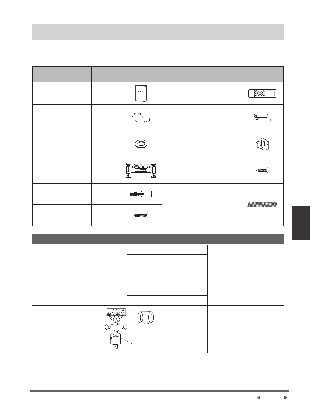
Page 17
Accessoires
Accessoires
/HV\VWqPHGHFOLPDWLVDWLRQHVWOLYUpDYHFOHVDFFHVVRLUHVVXLYDQWV8WLOLVH]WRXWHVOHVSLqFHVGLQVWDOODWLRQHWWRXV
OHVDFFHVVRLUHVSRXULQVWDOOHUOHFOLPDWLVHXU8QHPDXYDLVHLQVWDOODWLRQSHXWHQWUDvQHUXQHIXLWHGHDXXQFKRF
pOHFWULTXHHWXQLQFHQGLHRXSURYRTXHUXQHGpIDLOODQFHGHOpTXLSHPHQW/HVDUWLFOHVTXLQHVRQWSDVLQFOXVDYHF
le climatiseur doivent être achetés séparément.
Désignation des
accessoires
4Wp8 )RUPH
Désignation des
accessoires
4WpSF )RUPH
Manuel
Télécommande 1
-RLQWGHGUDLQDJH
SRXUOHVPRGqOHVGH
UHIURLGLVVHPHQWHWGH
FKDXIIDJH
1
%DWWHULH 2
-RLQW
SRXUOHPRGqOHGH
UHIURLGLVVHPHQW
FKDXIIDJH
1
Support de
télécommande
RSWLRQ
1
Plaque de montage 1
9LVGH¿[DWLRQ
pour support de
la télécommande
RSWLRQ
2
Ancre
VHORQOHV
PRGqOHV
3HWLW¿OWUH
'RLWrWUHLQVWDOOpj
ODUULqUHGX¿OWUHj
air principal par le
WHFKQLFLHQDXWRULVp
lors de l'installation
GHODPDFKLQH
1~2
VHORQOHV
PRGqOHV
9LVGH¿[DWLRQGHOD
plaque de montage
5~8
VHORQOHV
PRGqOHV
Désignation )RUPH 4XDQWLWp3&
Assemblage de tuyaux de
raccordement
Côté liquide
¡SRXFH
/HVSLqFHVTXHYRXVGHYH]
DFKHWHUVpSDUpPHQW Consultez
le revendeur pour connaître la taille
de tuyau approprié de l'appareil que
vous avez acheté.
¡SRXFH
&{WpJD]
¡SRXFH
¡SRXFH
¡SRXFH
¡SRXFH
Anneau et ceinture
magnétiques
VLOHVWIRXUQLYHXLOOH]YRXV
UpIpUHUDXVFKpPDGHFkEODJH
SRXUOLQVWDOOHUVXUOHFkEOHGH
FRQQH[LRQ
3DVVH]ODFHLQWXUHjWUDYHUVOH
trou de l’anneau magnétique
SRXUOD¿[HUDXFkEOH
,OVYDULHQWVHORQOHPRGqOH
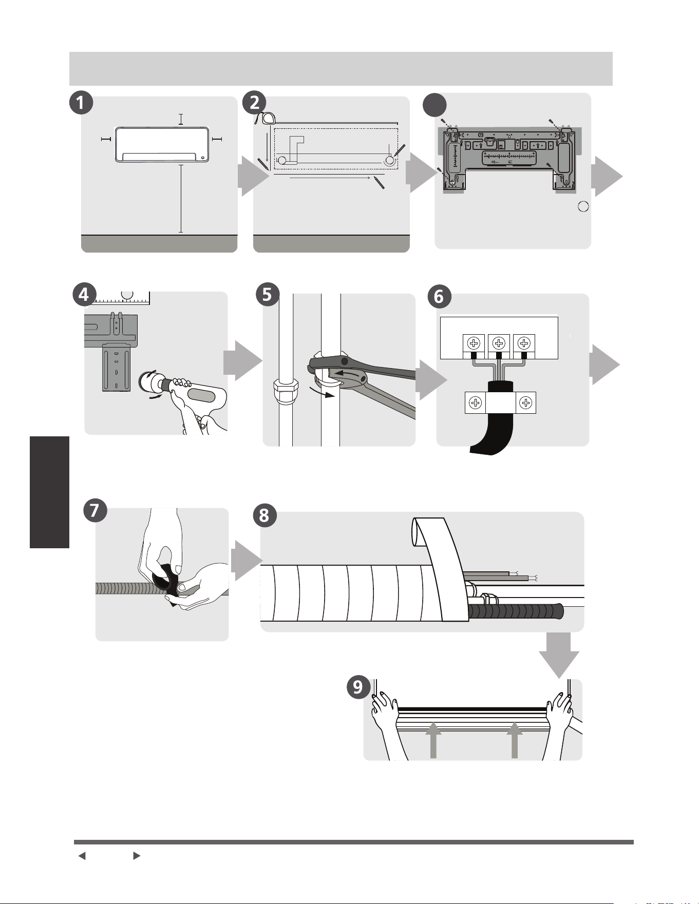
Page 18
Aperçu de
l'installation
Résumé de l’installation - Unité Intérieure
3
FROM EDGE TO HOLE CENTER:50mm
FROM EDGE TO HOLE CENTER:100mm
150
100
100
100
50
50
50
2
2
2
4
4
4
6
RECOMMAND
LIQUID
GAS
BUBBLE
LEVEL
mm
inch
mm
inch
6pOHFWLRQQH]O¶HPSODFHPHQW
d’installation
3HUFH]XQWURXGHPXU
3UpSDUH]OHVWX\DX[GH
drainage
'pWHUPLQH]ODSRVLWLRQGXWURX
dans le mur
&RQQHFWH]OHVWX\DX[
,QVWDOOH]O¶XQLWpLQWpULHXUH
(QURXOH]ODWX\DXWHULHHWOHVFkEOHV
QRQDSSOLFDEOHSRXUFHUWDLQVHQGURLWVHQ$PpULTXHGX
1RUG
)L[H]ODSODTXHGHPRQWDJH
&RQQHFWH]OHFkEODJH
QRQDSSOLFDEOHSRXUFHUWDLQV
HQGURLWVHQ$PpULTXHGX1RUG
12 cm
pouces)
12 cm
pouces)
La distance par rapport au plafond est
déterminée par la méthode d'installation.
PSRXFHV
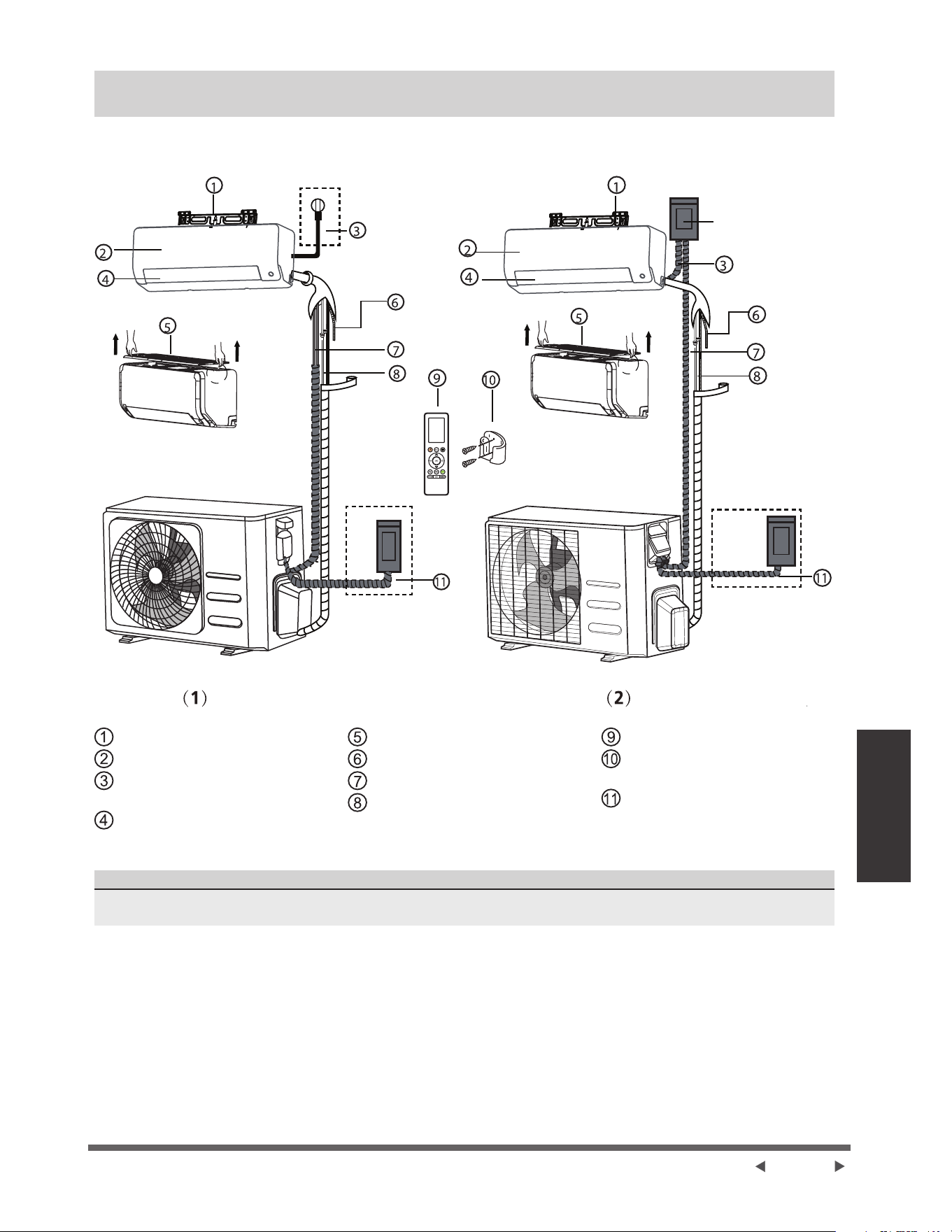
Page 19
Pièces de l’appareil
Pièces de l’appareil
NOTE : /LQVWDOODWLRQGRLWrWUHUpDOLVpHFRQIRUPpPHQWDX[H[LJHQFHVGHVQRUPHVORFDOHVHWQDWLRQDOHV/LQVWDOODWLRQ
SHXWrWUHOpJqUHPHQWGLIIpUHQWHVHORQOHVUpJLRQV
Disjoncteur à air
3ODTXHGHPRQWDJHGHPXU
Panneau avant
&kEOHGDOLPHQWDWLRQFHUWDLQHV
XQLWpV
Volet
)LOWUHjDLUjUHWLUHU
7X\DXGHGUDLQDJH
&kEOHGHVLJQDO
7X\DXWHULHGHUpIULJpUDQW
Télécommande
6XSSRUWGHWpOpFRPPDQGH
FHUWDLQHVXQLWpV
&kEOHG¶DOLPHQWDWLRQG¶XQLWp
H[WpULHXUHFHUWDLQHVXQLWpV
NOTE SUR LES ILLUSTRATIONS
/HVLOOXVWUDWLRQVGHFHPDQXHOVRQWjWLWUHH[SOLFDWLI/DIRUPHUpHOOHGHYRWUHXQLWpLQWpULHXUHSHXWrWUHOpJqUHPHQW
différente. La forme réelle doit prévaloir.
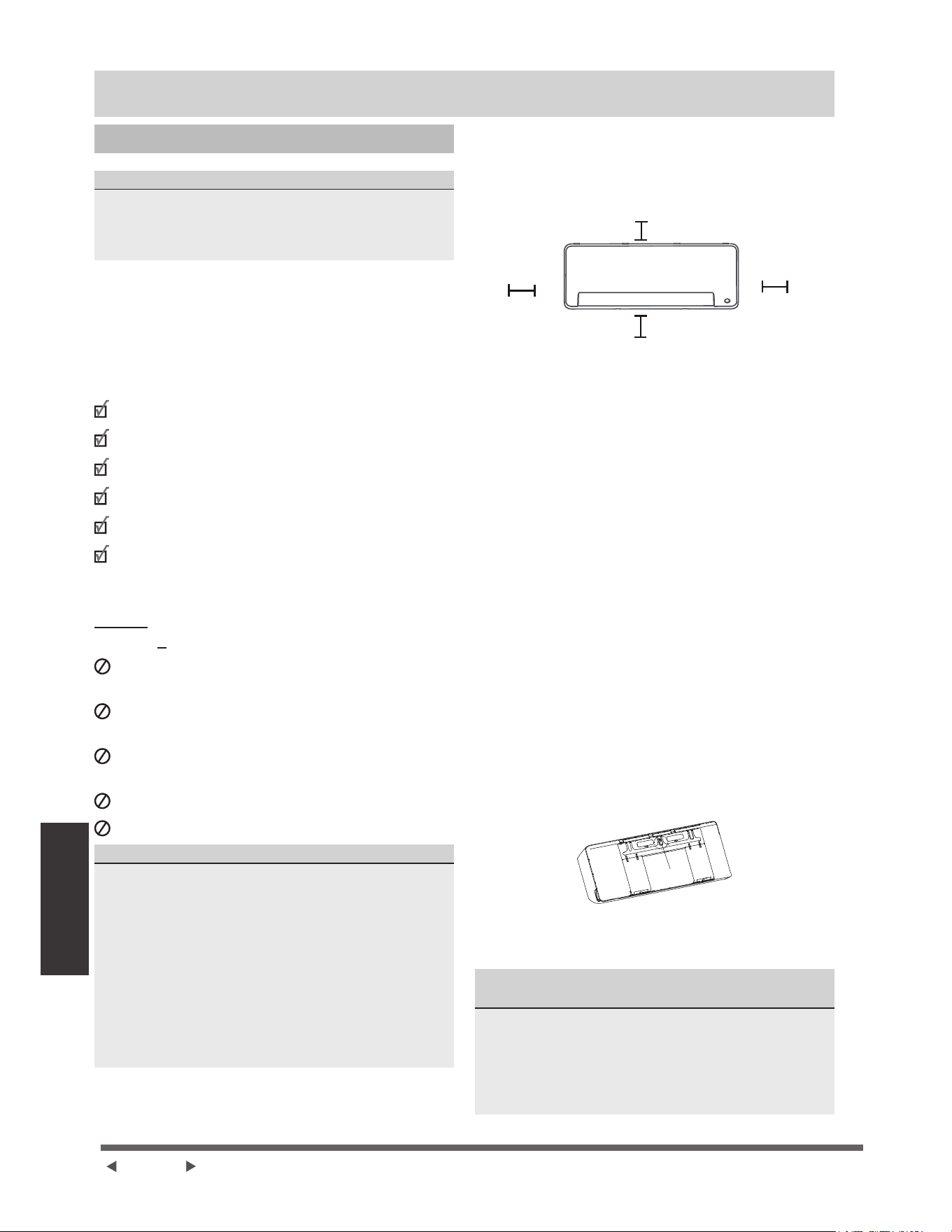
Page 20
Installation de
l'unité intérieure
Installation de l'unité intérieure
Instructions de l’installation - Unité intérieure
AVANT L’INSTALLATION
$YDQWG¶LQVWDOOHUO¶XQLWpLQWpULHXUHUHSRUWH]YRXVj
O¶pWLTXHWWH¿JXUDQWVXUO¶HPEDOODJHGXSURGXLWSRXU
DVVXUHUTXHOHQXPpURGHPRGqOHGHO¶XQLWpLQWpULHXUH
FRUUHVSRQGDXQXPpURGHPRGqOHGHO¶XQLWpH[WpULHXUH
eWDSH6pOHFWLRQQH]OHOLHXGLQVWDOODWLRQ
$YDQWG¶LQVWDOOHUO¶XQLWpLQWpULHXUHYRXVGHYH]FKRLVLUXQ
emplacement approprié. Les normes suivantes vous
aideront à sélectionner un emplacement approprié pour
l’appareil.
Emplacement approprié d'installation doit répondre
aux normes suivantes :
Bonne circulation de l'air
'UDLQDJHSUDWLTXH
/HEUXLWGHO¶DSSDUHLOQHGpUDQJHUDSDVOHVDXWUHV
)HUPHHWVROLGHO¶HPSODFHPHQWQHYLEUHSDV
6XI¿VDPPHQWVROLGHSRXUVXSSRUWHUOHSRLGVGHO¶DSSDUHLO
8QHPSODFHPHQWVLWXpjDXPRLQVXQPqWUHGH
WRXVOHVDXWUHVDSSDUHLOVpOHFWULTXHVSDUH[HPSOH
WpOpYLVLRQUDGLRRUGLQDWHXU
NE PAS installer l’appareil dans les endroits
suivants :
¬SUR[LPLWpGHWRXWHVRXUFHGHFKDOHXUGHYDSHXU
RXGHJD]FRPEXVWLEOH
¬SUR[LPLWpG¶DUWLFOHVLQÀDPPDEOHVWHOVTXHGHV
ULGHDX[RXGHVYrWHPHQWV
¬SUR[LPLWpGHWRXWREVWDFOHVXVFHSWLEOHGHEORTXHU
la circulation d’air
3UqVGHODSRUWH
'DQVXQHQGURLWVRXPLVjODOXPLqUHGLUHFWHGXVROHLO
NOTE SUR LE TROU DANS LE MUR :
6LOQ\DSDVGHWX\DXWHULHIULJRUL¿TXH¿[H
/RUVTXHYRXVFKRLVLVVH]XQHPSODFHPHQWVDFKH]TXH
YRXVGHYH]ODLVVHUVXI¿VDPPHQWGHSODFHSRXUXQWURX
GDQVOHPXUYRLUO¶pWDSHPercer un trou dans le mur
pour la tuyauterie de connexionGXFkEOHGHVLJQDO
HWGHODWX\DXWHULHGHUpIULJpUDQWUHOLDQWOHVXQLWpV
LQWpULHXUHVHWH[WpULHXUHV La position par défaut pour
WRXWHODWX\DXWHULHHVWOHF{WpGURLWGHO¶XQLWpLQWpULHXUH
HQIDFHGHO¶DSSDUHLO&HSHQGDQWO¶DSSDUHLOSHXW
DFFXHLOOLUGHVWX\DX[jJDXFKHHWjGURLWH
&RQVXOWHUOHGLDJUDPPHVXLYDQWD¿QG¶DVVXUHUOD
ERQQHGLVWDQFHDYHFOHVPXUVHWOHSODIRQG
La distance par rapport au plafond est
déterminée par la méthode d'installation.
PSRXFHVRXSOXV
FP
SRXFHVRX
plus
FP
SRXFHVRXSOXV
NOTE :
Ɣ 6LYRXVQ¶DYH]SDVEHVRLQGXVXSSRUWDUULqUH
pour soutenir l’unité :
7HUPLQH]OHVFRQQH[LRQVGHVWX\DX[HWGHVFkEOHV
DYDQWGHPRQWHUOXQLWpLQWpULHXUHVXUOHPXU6L
ODKDXWHXUGLQVWDOODWLRQHVWOLPLWpHXQHGLVWDQFH
GHFPGXSODIRQGHVWDXWRULVpHPDLVFHODSHXW
UpGXLUHOHVSHUIRUPDQFHVGXSURGXLW3RXUJDUDQWLU
XQHVSDFHVXI¿VDQWSRXULQVWDOOHUHWUHWLUHUOH¿OWUH
jDLUVXSpULHXUPDLQWHQH]DXPRLQVFPRXSOXV
du plafond.
Ɣ 6LYRXVDYH]EHVRLQGXVXSSRUWDUULqUHSRXU
soutenir l’unité :
6LOHWX\DXHWOHFkEOHVRQWUDFFRUGpVDYHFOH
SDQQHDXDYDQWRXYHUWODGLVWDQFHPLQLPDOHGX
SODIRQGHVWGHFPRXSOXVVLOHWX\DXHWOHFkEOH
VRQWUDFFRUGpVVDQVOHSDQQHDXDYDQWjHQOHYHU
la distance minimale du plafond est de 11 cm ou
plus.
eWDSH)L[H]ODSODTXH de montage au mur
/DSODTXHGHPRQWDJHHVWO¶DSSDUHLOVXUOHTXHOYRXV
monterez l’unité intérieure.
Ɣ 5HWLUH]ODYLVTXL¿[HODSODTXHGHPRQWDJHj
ODUULqUHGHOXQLWpLQWpULHXUH
Vis
Ɣ )L[H]ODSODTXHGHPRQWDJHDXPXUDYHFOHVYLV
IRXUQLHV$VVXUH]YRXVTXHODSODTXHGHPRQWDJH
HVWELHQjSODWFRQWUHOHPXU
NOTE POUR LES MURS EN %e721 28(1%5,48(
:
6LOHPXUHVWHQEULTXHEpWRQRXPDWpULDXVLPLODLUH
SHUFH]GHVWURXVGHGLDPqWUHGHPPGLDPqWUH
SRXFHGDQVOHPXUHWLQVpUH]OHVDQFUDJHVGH
PDQFKRQIRXUQLV3XLV¿[H]ODSODTXHGHPRQWDJHDX
PXUHQVHUUDQWOHVYLVGLUHFWHPHQWGDQVOHVDQFUDJHV
d’attache.
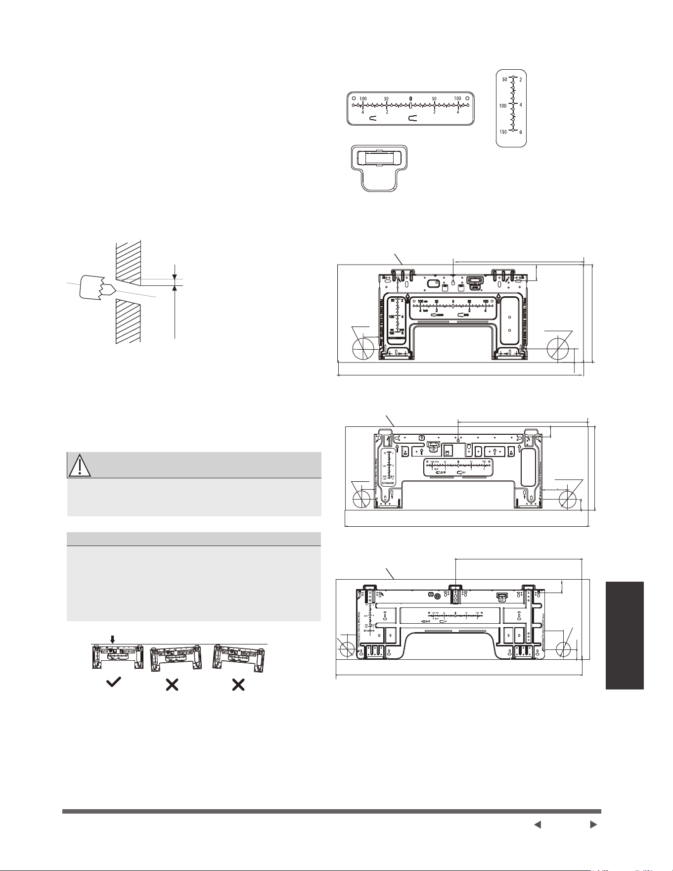
Page 21
Installation de
l'unité intérieure
eWDSH3HUFH]XQWURXGDQVOHPXUSRXUOD
tuyauterie de connexion
1. Déterminez l'emplacement du trou dans le mur
HQYRXVEDVDQWVXUODSRVLWLRQGHODSODTXHGH
PRQWDJH5HSRUWH]DX[Dimensions de la plaque
de montage.
2. (QXWLOLVDQWXQFDURWWLHUGHPPSRXFHVRX
PPSRXFHVVHORQOHVPRGqOHVSHUFH]
XQWURXGDQVOHPXU$VVXUH]YRXVTXHOHWURXHVW
SHUFpjXQDQJOHOpJqUHPHQWGHVFHQGDQWGHVRUWH
TXHO¶H[WUpPLWpH[WpULHXUHGXWURXVRLWSOXVEDVVH
TXHO¶H[WUpPLWpLQWpULHXUHG¶HQYLURQPPjPP
jSRXFH&HODDVVXUHUDXQERQGUDLQDJHGH
l’eau.
0XU
Intérieur ([WpULHXU
PP
SRXFH
NOTE :/RUVTXHOHWX\DXGHUDFFRUGHPHQWjF{Wp
JD]HVWGHĭPPSRXFHRXSOXVOHWURX
GDQVOHPXUGRLWrWUHGHPPSRXFHV
3. Placez le manchon de protection dans le trou. Cela
SURWqJHOHVERUGVGXWURXHWDLGHUDjOHVFHOOHUjOD
¿QGXSURFHVVXVG¶LQVWDOODWLRQ
ATTENTION
/RUVGHSHUFHUOHWURXVXUOHPXUDVVXUH]YRXV
G¶pYLWHUOHV¿OVODSORPEHULHHWOHVDXWUHVFRPSRVDQWV
VHQVLEOHV
',0(16,216'(3/$48('(0217$*(
'LIIpUHQWVPRGqOHVRQWGLIIpUHQWHVSODTXHVGH
PRQWDJH3RXUIDFLOLWHUOLQVWDOODWLRQLO\DXQQLYHDX
jEXOOHGHVGLPHQVLRQVJUDYpHVVXUODSODTXHGH
PRQWDJH9HXLOOH]LQVWDOOHUODSODTXHHWSHUFHUXQ
trou dans le mur selon les indications de la plaque de
PRQWDJH9RLUOHV¿JXUHVFLGHVVRXV
2ULHQWDWLRQFRUUHFWHGHODSODTXHGHPRQWDJH
8QLWpPPSRXFH
5qJOHGHGLUHFWLRQKRUL]RQWDOH
5qJOHGH
direction
verticale
RECOMMANDER
NIVEAU À
BULLES
mm
mm
LIQUIDE
GAZ
Pouce
Pouce
ATTENTION :/HQLYHDXjEXOOHVXUODSODTXHGH
PRQWDJHQHSHXWSDVrWUHHQOHYp6LOHVWFDVVpYHLOOH]
à nettoyer le liquide qui fuit.
)RUPHGHO¶XQLWpLQWpULHXU
)RUPHGHO¶XQLWpLQWpULHXU
)RUPHGHO¶XQLWpLQWpULHXU
120(4.7)
795(31)
965(38)
1140(44.8)
50(1.9)
50(1.9)
50(1.9)
Modèle A
0RGqOH%
Modèle C
trou de tuyau
ĭ
trou de tuyau
ĭ
trou de
WX\DXĭ
(2.5)
trou de
WX\DXĭ
(2.5)
trou de tuyau
ĭ
trou de tuyau
ĭ
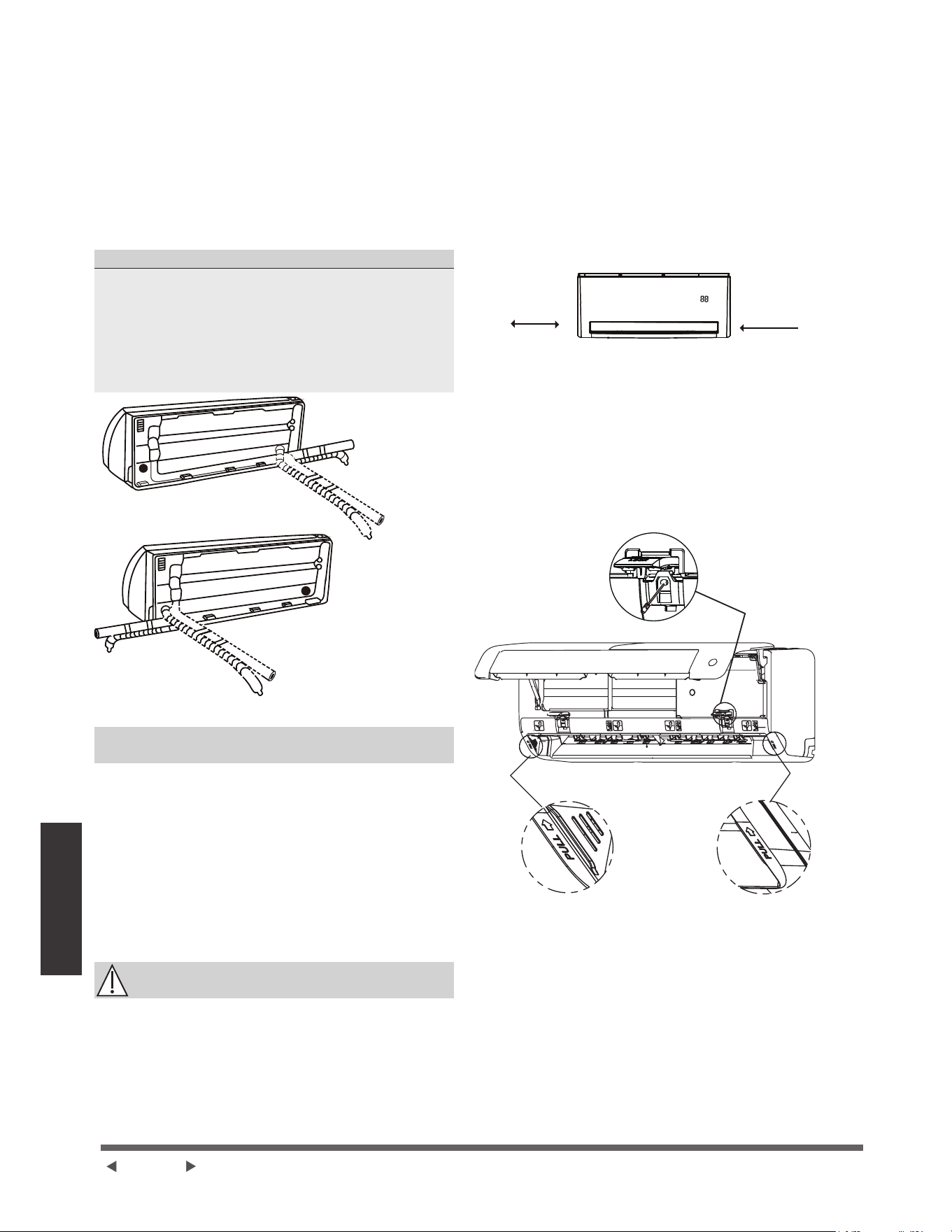
Page 22
Installation de
l'unité intérieure
eWDSH3UpSDUH]ODWX\DXWHULHGHUpIULJpUDQW
/DWX\DXWHULHGHUpIULJpUDQWVHWURXYHjO¶LQWpULHXUG¶XQ
PDQFKRQLVRODQW¿[pjO¶DUULqUHGHO¶DSSDUHLO9RXV
devez préparer la tuyauterie avant de la faire passer
par le trou dans le mur. 5pIpUH]YRXVjODVHFWLRQ
5DFFRUGHPHQWGHODWX\DXWHULHGHUpIULJpUDQW de
FHPDQXHOSRXUREWHQLUGHVLQVWUXFWLRQVGpWDLOOpHVVXU
OHVFRQGLWLRQVOHVWHFKQLTXHVHWFGHGpULYDWLRQHWGH
torque de tuyau.
127(685/(6$1*/(6'(78<$8;
/DWX\DXWHULHGHUpIULJpUDQWSHXWVRUWLUGHO¶XQLWp
LQWpULHXUHGHTXDWUHDQJOHVGLIIpUHQWV
Ɣ &{WpjJDXFKH
Ɣ $UULqUHJDXFKH
Ɣ &{WpjGURLWH
Ɣ $UULqUHGURLWH
9RLUOHV¿JXUHV suivantes pour plus de détails.
NOTE SUR LE RACCORDEMENT DE LA
TUYAUTERIE
Ɣ 'DQVFHUWDLQHVUpJLRQVGHVeWDWV8QLVXQWXEHGH
FRQGXLWHGRLWrWUHXWLOLVpSRXUFRQQHFWHUOHFkEOH
3RXUJDUDQWLUXQHVSDFHVXI¿VDQWSRXUOHSDVVDJH
GHVWX\DX[HWSRXUTXHODSSDUHLOVRLWFRQWUHOHPXU
DSUqVOLQVWDOODWLRQLOHVWUHFRPPDQGpGH¿[HUOH
WX\DXGHYLGDQJHVXUOHF{WpGURLWORUVTXHYRXV
rWHVIDFHjODUULqUHGHODSSDUHLO
Ɣ /RUVTXHYRXVFKRLVLVVH]XQHWX\DXWHULHjJDXFKH
RXjGURLWHYHXLOOH]YRXVDVVXUHUTXHOHVWX\DX[
VRUWHQWKRUL]RQWDOHPHQWD¿QGHQHSDVDIIHFWHU
l'installation du panneau inférieur.
ATTENTION
)DLWHVDWWHQWLRQjQHSDVGpIRUPHURXHQGRPPDJHU
la tuyauterie tout en les pliant loin de l’appareil. Toute
¿VVXUHGDQVODWX\DXWHULHDIIHFWHUDOHVSHUIRUPDQFHVGH
l’appareil.
6LDXFXQHFDQDOLVDWLRQGHUpIULJpUDQWQHVW
encastrée dans le murSURFpGH]FRPPHVXLW
eWDSH$FFURFKH]OXQLWpLQWpULHXUHVXUODSODTXH
de montage :
1. 1RXEOLH]SDVTXHOHVFURFKHWVGHODSODTXHGH
PRQWDJHVRQWSOXVSHWLWVTXHOHVWURXVjODUULqUH
GHODSSDUHLO6LYRXVWURXYH]TXHYRXVQDYH]
SDVDVVH]GHSODFHSRXUUDFFRUGHUGHVWX\DX[
HQFDVWUpVjOXQLWpLQWpULHXUHOXQLWpSHXWrWUHUpJOpH
jJDXFKHRXjGURLWHGHQYLURQPP
SRXFHVVHORQOHPRGqOH
PP
SRXFHV
PP
SRXFHV
'pSODFHUjJDXFKHRXjGURLWH
eWDSH3UpSDUH]ODWX\DXWHULHGHUpIULJpUDQW
1. 2XYUH]HW¿[H]ODSRVLWLRQGXSDQQHDXSXLVRXYUH]
OHVFRXYHUFOHVGHVGHX[EORFVGHYHUURXLOODJH
GpYLVVH]ODYLVLQGLTXpHVXUODSKRWRFLGHVVRXV
SXLVPDLQWHQH]OHVGHX[F{WpVGXSDQQHDXLQIpULHXU
jOHQGURLWPDUTXp©38//ªWLUH]YHUVOHKDXW
SRXUOLEpUHUOHVERXFOHVSXLVIDLWHVGHVFHQGUHOH
panneau inférieur.
2XYUH]OH
couvercle et
dévissez la vis
Modèle A
AUTO COOL
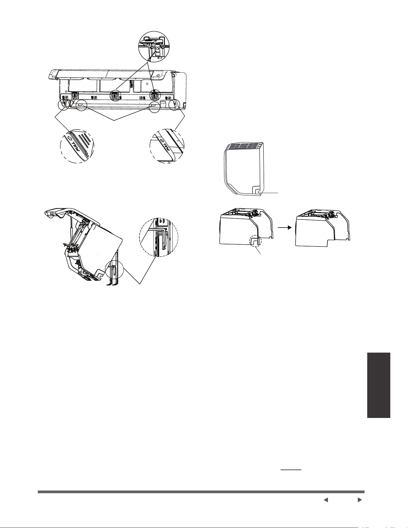
Page 23
Installation de
l'unité intérieure
2XYULUOH
couvercle et
dévisser la vis
Dévisser les
vis
0RGqOH%
8WLOLVH]OHVXSSRUWjODUULqUHGHODSSDUHLOSRXU
VRXWHQLUODSSDUHLOFHTXLYRXVGRQQHUDDVVH]
GHVSDFHSRXUEUDQFKHUODWX\DXWHULHGXUpIULJpUDQW
OHFkEOHGHVLJQDOLVDWLRQHWOHWX\DXGHYLGDQJH
8WLOLVH]OHVXSSRUWjODUULqUH
de l'appareil contre la plaque
GHPRQWDJHSRXUVRXWHQLU
l'appareil
Étape 3.&RQQHFWH]OHWX\DXGHGUDLQDJHHWOD
WX\DXWHULHGHUpIULJpUDQWUpIpUHUjODVHFWLRQ
5DFFRUGHPHQWGHOD7X\DXWHULHGH5pIULJpUDQW de ce
PDQXHOSRXUOHVLQVWUXFWLRQV
Étape 4.0DLQWHQH]OHSRLQWGHUDFFRUGHPHQWGXWX\DX
H[SRVpSRXUHIIHFWXHUOHWHVWGHIXLWHYRLUODVHFWLRQ
9pUL¿FDWLRQVpOHFWULTXHVHWYpUL¿FDWLRQVGHIXLWHVde
FHPDQXHO
Étape 5.$SUqVOHWHVWGpWDQFKpLWpHQYHORSSH]OHSRLQW
GHFRQQH[LRQDYHFGXUXEDQLVRODQW
Étape 6. Retirez le support ou le coin qui supporte
l’appareil.
Étape 7.(QH[HUoDQWXQHSUHVVLRQXQLIRUPHDSSX\H]
sur la moitié inférieure de l'appareil. Continuez à
SRXVVHUYHUVOHEDVMXVTXjFHTXHOXQLWpVHQFOHQFKH
VXUOHVFURFKHWVVLWXpVDXEDVGHODSODTXHGHPRQWDJH
6LDXFXQHFDQDOLVDWLRQGHUpIULJpUDQWQHVW
encastrée dans le murSURFpGH]FRPPHVXLW
1. En fonction de la position du trou mural par rapport
jODSODTXHGHPRQWDJHFKRLVLVVH]OHF{WpSDU
lequel la tuyauterie sortira de l'appareil.
6LOHWURXGDQVOHPXUVHWURXYHGHUULqUHODSSDUHLO
JDUGH]OHSDQQHDXNQRFNRXWHQSODFH6LOHWURX
GDQVOHPXUHVWVLWXpVXUOHF{WpGHO¶XQLWpLQWpULHXUH
UHWLUH]OHSDQQHDXNQRFNRXWHQSODVWLTXHGHFHF{Wp
de l’appareil.
9RLUOD¿JXUHFLGHVVRXV&HODFUpHUDXQHIHQWHj
travers laquelle votre tuyau peut sortir de l’appareil.
8WLOLVH]XQHSLQFHjEHFHI¿OpVLOHSDQQHDXHQ
SODVWLTXHHVWWURSGLI¿FLOHjUHWLUHUjODPDLQ
3DQQHDXNQRFNRXW
GpFRXSpHQIRQFWLRQGHOD
WDLOOHUpHOOHQpFHVVDLUH
6LYRXVGHYH]GpFRXSHUOHSDQQHDX
HQSODVWLTXHGHJUDQGHWDLOOHSURFpGH]
FRPPHLQGLTXpFLGHVVXV
8WLOLVH]GHVFLVHDX[SRXUFRXSHUODORQJXHXUGX
PDQFKRQLVRODQWD¿QGHUpYpOHUHQYLURQPP
SRXFHVGHWX\DXGHUpIULJpUDQW&HODVHUWjGHX[
¿QV
Ɣ Pour faciliter le processus de Raccordement de
ODWX\DXWHULHGHUpIULJpUDQW.
Ɣ Pour faciliter les &RQWU{OHVGHIXLWHVGHJD] et
YRXVSHUPHWWUHGHYpUL¿HUOHVERVVHV
8WLOLVH]OHVXSSRUWjODUULqUHGHODSSDUHLOSRXU
VRXWHQLUODSSDUHLOFHTXLYRXVGRQQHUDDVVH]
GHVSDFHSRXUEUDQFKHUODWX\DXWHULHGXUpIULJpUDQW
OHFkEOHGHVLJQDOLVDWLRQHWOHWX\DXGHYLGDQJH
&RQQHFWH]ODWX\DXWHULHGHUpIULJpUDQWGHOXQLWp
intérieure à la tuyauterie de raccordement
qui permettra de relier les unités intérieures
HWH[WpULHXUHV9HXLOOH]UpIpUHUjODVHFWLRQ
5DFFRUGHPHQWGHOD7X\DXWHULHGH5pIULJpUDQW de
ce manuel pour des instructions détaillées.
6. Basé sur la position du trou par rapport à la plaque
GHPRQWDJHPXUDOGpWHUPLQH]O¶DQJOHQpFHVVDLUHGH
votre tuyauterie.
6DLVLVVH]ODWX\DXWHULHGHUpIULJpUDQWjODEDVHGX
coude.
/HQWHPHQWDYHFXQHSUHVVLRQXQLIRUPHSOLH]
la tuyauterie vers le trou. Ne pas déformer ou
HQGRPPDJHUODWX\DXWHULHDXFRXUVGXSURFHVVXV
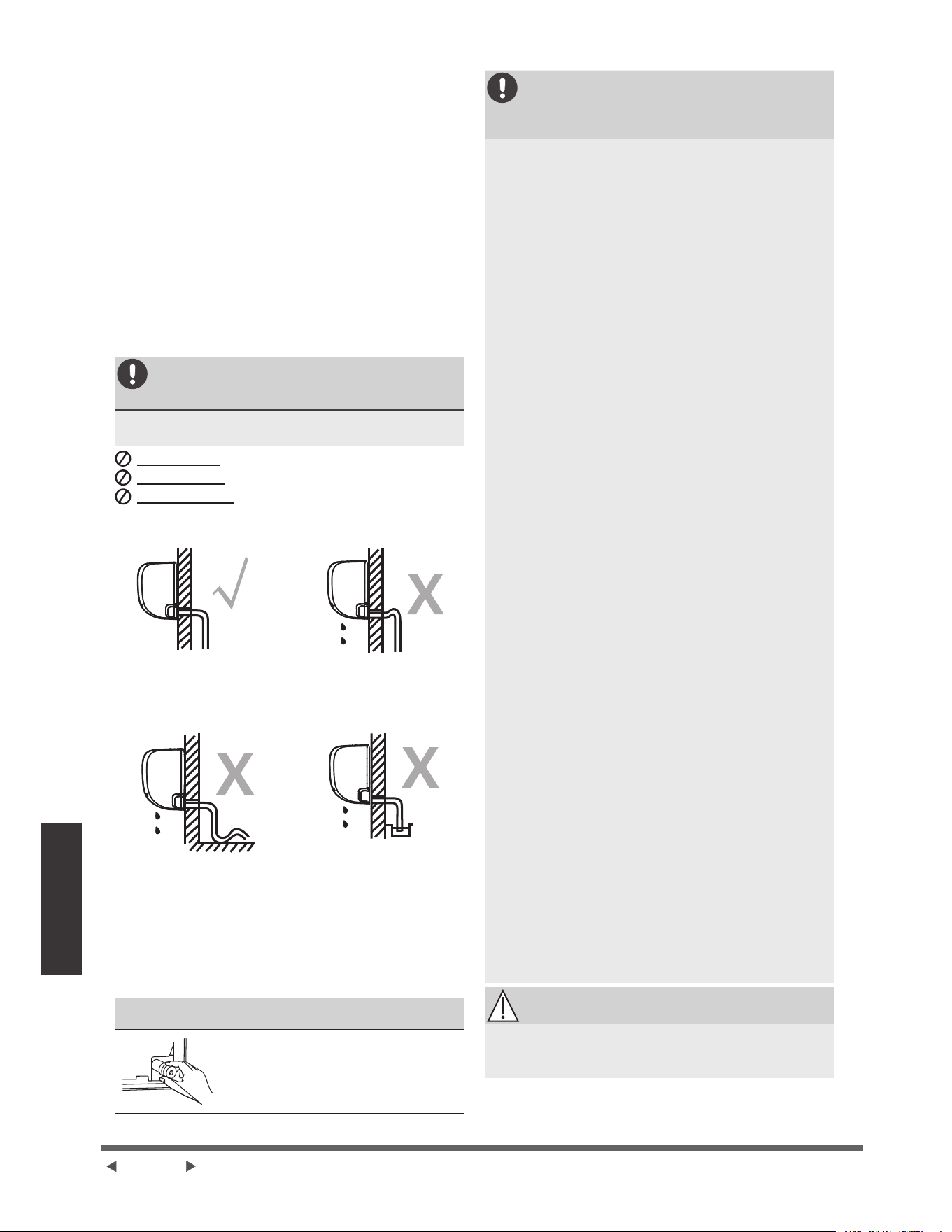
Page 24
Installation de
l'unité intérieure
Étape 5 : Connecter le tuyau de drainage
3DUGpIDXWOHWX\DXGHGUDLQDJHHVW¿[pjODJDXFKH
GHO¶DSSDUHLOORUVTXHYRXVrWUHHQIDFHGHO¶DSSDUHLO
&HSHQGDQWLOSHXWpJDOHPHQWrWUH¿[pDXF{Wp
GURLW3RXUDVVXUHUXQERQGUDLQDJH¿[H]OHWX\DX
GHGUDLQDJHGXPrPHF{WpTXHYRWUHWX\DXWHULHGH
UpIULJpUDQWTXLWWHO¶XQLWp
NOTE :'DQVFHUWDLQHVUpJLRQVGHVeWDWV8QLVVL
OHSDQQHDXGHFRQGXLWHHVWLQVWDOOpVXUODPDFKLQH
YHXLOOH]FKRLVLUOHGUDLQDJHDXF{WpGURLW
Ɣ (QYHORSSH]IHUPHPHQWOHSRLQWGHFRQQH[LRQ
DYHFGXUXEDQWpÀRQSRXUDVVXUHUXQHERQQH
pWDQFKpLWpHWpYLWHUOHVIXLWHV
Ɣ (QOHYH]OH¿OWUHjDLUHWYHUVH]XQHSHWLWHTXDQWLWp
G¶HDXGDQVOHEDFGHGUDLQDJHSRXUYRXVDVVXUHU
TXHO¶HDXV¶pFRXOHGHO¶DSSDUHLOHQGRXFHXU
NOTE SUR LA POSITION DU TUYAU DE
DRAINAGE
9HLOOH]jGLVSRVHUOHWX\DXGHYLGDQJHVHORQOHV
¿JXUHVVXLYDQWHV
Ne pas plierOHWX\DXGHYLGDQJH
Ne pas créerSURYRTXHUGHO¶HDXVWDJQDQWH
Ne pas mettreO¶H[WUpPLWpGXWX\DXGHYLGDQJH
GDQVGHO¶HDXRXGDQVXQUpFLSLHQWVXVFHSWLEOHGH
UHFXHLOOLUO¶HDX
CORRECT
$VVXUH]YRXVTXHOHWX\DXGH
drainage
ne soit pas
plié ou
¿VVXUpSRXUDVVXUHUXQERQ
pWDW
INCORRECT
Des plis dans le tuyau
de drainage
FUpHURQW
GHVSLqJHVjHDX
INCORRECT
8QFRXGHGDQVOH
tuyau de drainage peut
provoquer de l'eau
VWDJQDQWH
INCORRECT
1HSDVPHWWUHO¶H[WUpPLWpGX
tuyau de drainage dans de
O¶HDXRXGDQVXQUpFLSLHQW
VXVFHSWLEOHGHUHFXHLOOLU
O¶HDX
&HODHPSrFKHUDXQ
GUDLQDJHDGpTXDW
BOUCHER LE TROU DE DRAINAGE INUTILISÉ
3RXUpYLWHUOHVIXLWHVLQGpVLUDEOHV
YRXVGHYH]ERXFKHUOHWURXGH
GUDLQDJHQRQXWLOLVpDYHFOH
ERXFKRQHQFDRXWFKRXFIRXUQL
AVANT D’EFFECTUER TOUTE
OPÉRATION SOUS TENSION,
LISEZ CES RÈGLEMENTS
7RXWOHFkEODJHGRLWrWUHFRQIRUPHDX[FRGHV
pOHFWULTXHVORFDX[HWQDWLRQDX[HWGRLWrWUH
LQVWDOOpSDUXQpOHFWULFLHQDJUpp
7RXVOHVUDFFRUGHPHQWVpOHFWULTXHVGRLYHQW
rWUHHႇHFWXpVFRQIRUPpPHQWDXVFKpPDGH
UDFFRUGHPHQWpOHFWULTXHVLWXpVXUOHVSDQQHDX[
GHVXQLWpVLQWpULHXUHHWH[WpULHXUH
(QFDVGHSUREOqPHGHVpFXULWpJUDYHDYHF
O¶DOLPHQWDWLRQpOHFWULTXHDUUrWH]LPPpGLDWHPHQW
OHWUDYDLO([SOLTXH]YRWUHUDLVRQQHPHQWDXFOLHQW
HWUHIXVH]G¶LQVWDOOHUO¶XQLWpMXVTX¶jFHTXHOH
SUREOqPHGHVpFXULWpVRLWFRUUHFWHPHQWUpVROX
/DWHQVLRQG¶DOLPHQWDWLRQGRLWrWUHFRPSULVH
HQWUHHWGHODWHQVLRQQRPLQDOH8QH
DOLPHQWDWLRQLQVXႈVDQWHSHXWSURYRTXHUXQ
G\VIRQFWLRQQHPHQWXQFKRFpOHFWULTXHRXXQ
LQFHQGLH
6LYRXVUDFFRUGH]ODOLPHQWDWLRQjXQFkEODJH
¿[HLOIDXWLQVWDOOHUXQSDUDVXUWHQVHXUHWXQ
LQWHUUXSWHXUSULQFLSDO
6LYRXVUDFFRUGH]O¶DOLPHQWDWLRQjXQFkEODJH
¿[HXQLQWHUUXSWHXURXXQGLVMRQFWHXUTXL
GpFRQQHFWHWRXVOHVS{OHVHWSUpVHQWHXQH
VpSDUDWLRQGHFRQWDFWG¶DXPRLQVSRXFH
PPGRLWrWUHLQWpJUpDXFkEODJH¿[H/H
WHFKQLFLHQTXDOL¿pGRLWXWLOLVHUXQGLVMRQFWHXURX
XQLQWHUUXSWHXUDSSURXYp
1HEUDQFKH]O¶XQLWpTX¶jXQHSULVHGHFRXUDQW
LQGLYLGXHOOH1HSDVFRQQHFWHUXQHDXWUHXQLWpj
FHWWHSULVH
$VVXUH]YRXVGHELHQPHWWUHOHFOLPDWLVHXUjOD
WHUUH
&KDTXH¿OGRLWrWUHIHUPHPHQWFRQQHFWp8Q
FkEODJHGHVVHUUpSHXWSURYRTXHUXQHVXUFKDXႇH
GXWHUPLQDOHQWUDvQDQWXQG\VIRQFWLRQQHPHQWGX
SURGXLWHWXQULVTXHG¶LQFHQGLH
1HSDVODLVVHUOHVFkEOHVWRXFKHURXUHSRVHU
FRQWUHODWXEXOXUHGHUpIULJpUDQWOHFRPSUHVVHXU
RXWRXWHSLqFHPRELOHGDQVO¶XQLWp
6LO¶XQLWpHVWpTXLSpHG¶XQUpFKDXႇHXUpOHFWULTXH
DX[LOLDLUHHOOHGRLWrWUHLQVWDOOpHjDXPRLQV
PqWUHSRXFHVGHWRXWPDWpULDXFRPEXVWLEOH
3RXUpYLWHUWRXWULVTXHGHFKRFpOHFWULTXHQH
MDPDLVWRXFKHUOHVFRPSRVDQWVpOHFWULTXHV
LPPpGLDWHPHQWDSUqVODPLVHKRUVWHQVLRQ
$SUqVODPLVHKRUVWHQVLRQDWWHQGH]WRXMRXUV
PLQXWHVRXSOXVDYDQWGHWRXFKHUOHV
FRPSRVDQWVpOHFWULTXHV
AVERTISSEMENT
AVANT TOUTE OPÉRATION SOUS TENSION
OU CÂBLAGE, COUPEZ L’ALIMENTATION
PRINCIPALE DU SYSTÈME.
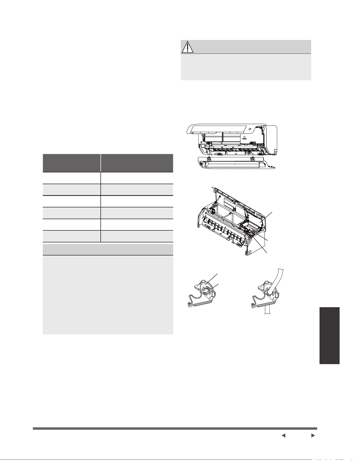
Page 25
Installation de
l'unité intérieure
Étape 6 : Connecter les câbles de signal et
d'alimentation
/HFkEOHGHVLJQDOSHUPHWODFRPPXQLFDWLRQHQWUHOHV
XQLWpVLQWpULHXUHHWH[WpULHXUH9RXVGHYH]G¶DERUG
FKRLVLUODERQQHWDLOOHGHFkEOHDYDQWGHOHSUpSDUHU
SRXUODFRQQH[LRQ
Types de câbles
Ɣ &kEOHG¶DOLPHQWDWLRQLQWpULHXUOHFDVpFKpDQW
+99)RX+99)
Ɣ Câble d’alimentation extérieur :+51)RX
+51)
Ɣ Câble de signal :+51)
NOTE :(Q$PpULTXHGX1RUGFKRLVLVVH]OHW\SH
GHFkEOHHQIRQFWLRQGHVFRGHVHWUpJOHPHQWDWLRQV
pOHFWULTXHVORFDX[
Section minimale des câbles d’alimentation et de
signaux (pour référence)
(Non applicable pour l’Amérique du Nord)
Courant nominal de
l’unité (A)
Section transversale
nominale (mm²)
!HW 0,75
!HW 1
!HW 1,5
!HW 2,5
!HW 4
!HW 6
CHOISIR LA BONNE TAILLE DU CABLE
/DWDLOOHGXFkEOHG¶DOLPHQWDWLRQGXFkEOHGH
VLJQDOGXIXVLEOHHWGXFRPPXWDWHXUQpFHVVDLUHV
HVWGpWHUPLQpHSDUOHFRXUDQWPD[LPDOGHO¶XQLWp
/HFRXUDQWPD[LPXPHVWLQGLTXpVXUODSODTXH
signalétique située sur le panneau latéral de
O¶XQLWp9HXLOOH]UpIpUHUjFHWWHSODTXHVLJQDOpWLTXH
SRXUFKRLVLUOHERQFkEOHOHERQIXVLEOHRXOHERQ
FRPPXWDWHXU
NOTE:(Q$PpULTXHGX1RUGYHXLOOH]FKRLVLUOD
ERQQHWDLOOHGHFkEOHHQIRQFWLRQGHO¶LQWHQVLWp
PLQLPDOHGXFLUFXLWLQGLTXpHVXUODSODTXH
VLJQDOpWLTXHGHO¶XQLWp
2XYUH]HW¿[H]ODSRVLWLRQGXSDQQHDXSXLV
RXYUH]OHVFRXYHUFOHVGHVGHX[EORFVGH
YHUURXLOODJHGpYLVVH]ODYLVSXLVPDLQWHQH]
OHVGHX[F{WpVGXSDQQHDXLQIpULHXUjOHQGURLW
PDUTXp©38//ªWLUH]YHUVOHKDXWSRXUOLEpUHU
OHVERXFOHVSXLVIDLWHVGHVFHQGUHOHSDQQHDX
LQIpULHXUYRLUSDJHV
2XYUH]OHFRXYHUFOHGHODERvWHj¿OSRXU
FRQQHFWHUOHFkEOH
'pYLVVHUOHVHUUHFkEOHVRXVODERvWHjERUQHHW
OHSODFHUVXUOHF{Wp
)DFHjO¶DUULqUHGHO¶XQLWpUHWLUH]OHSDQQHDXHQ
SODVWLTXHVLWXpHQEDVjJDXFKH
AVERTISSEMENT
TOUT LE CABLAGE DOIT ÊTRE RÉALISÉ
STRICTEMENT CONFORMÉMENT AU
DIAGRAMME DE CABLAGE SITUÉ À L’ARRIÈRE
DU PANNEAU AVANT DE L’UNITÉ INTÉRIEURE.
)DLWHVSDVVHUOH¿OGHVLJQDOjWUDYHUVFHWWHIHQWH
GHO¶DUULqUHGHO¶XQLWpYHUVO¶DYDQW
)DFHjO¶DYDQWGHO¶DSSDUHLOUHOLH]OH¿OVHORQ
OHVFKpPDGHFkEODJHGHO¶XQLWpLQWpULHXUH
FRQQHFWH]ODSDWWHHQ8HWYLVVH]IHUPHPHQW
FKDTXH¿OjODERUQHFRUUHVSRQGDQWH
2XYUH]GDERUGOHSDQQHDXDYDQWSXLV
UHWLUH]OHSDQQHDXLQIpULHXU
2XYUH]OH
FRXYHUFOHGH¿O
%RvWHjERUQH
6HUUHFkEOH
&KLFDQHjUDWVFHUWDLQHV
XQLWpV
Panneau
.QRFN2XW
NOTE :6LODWDLOOHGXFkEOHHVWWURSJUDQGHUHWLUH]
OHSHWLWSDQQHDXHQSODVWLTXHGXPLOLHXSRXUFUpHU
XQHIHQWHSDUODTXHOOHOHFkEOHSHXWVRUWLU6LYRXV
VRXKDLWH]UHWLUHUOHFKkVVLVRXOHWX\DXGHYLGDQJH
YHXLOOH]G¶DERUGUHWLUHUODFKLFDQHjUDWV
En Amérique du Nord
5HWLUH]G¶DERUGOHSDQQHDXG¶RXYHUWXUHSRXUFUpHU
XQHIHQWHGDQVODTXHOOHOHWXEHGHFRQGXLWHSHXW
V¶LQVWDOOHU(QVXLWHIDLWHVSDVVHUOHFkEOHSDUOHWXEH
GHFRQGXLWHHWFRQQHFWH]OHjO¶XQLWpLQWpULHXUH
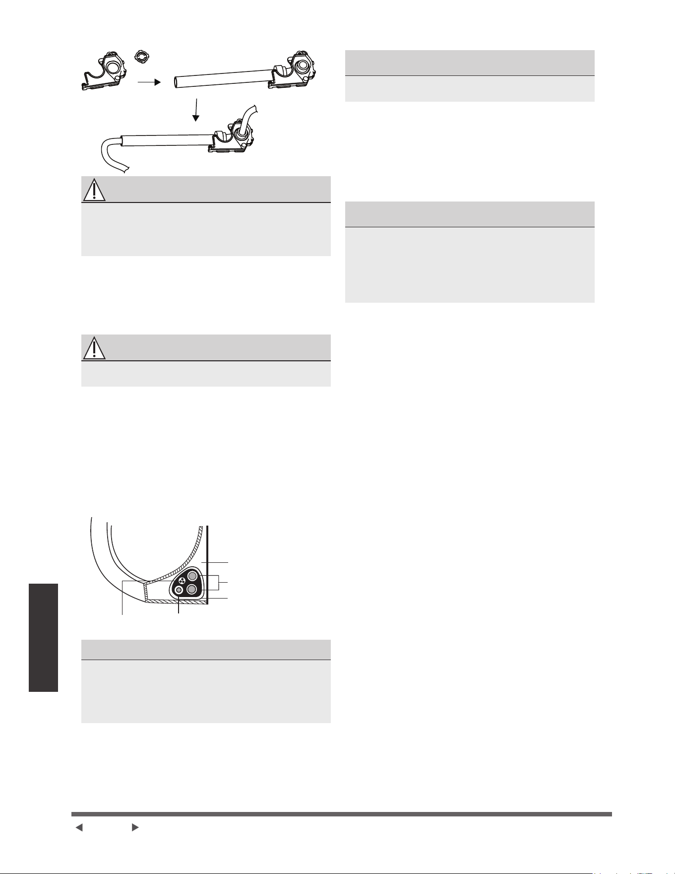
Page 26
Installation de
l'unité intérieure
ATTENTION
NE PAS MÉLANGER LA LIGNE SOUS TENSION
ET LA LIGNE NEUTRE
&HFLHVWGDQJHUHX[HWSHXWHQWUDvQHUXQ
G\VIRQFWLRQQHPHQWGXFOLPDWLVHXU
$SUqVDYRLUYpUL¿pTXHFKDTXHFRQQH[LRQHVW
VpFXULVpHXWLOLVHUOHVHUUHFkEOHSRXUDWWDFKHUOH
FkEOHGHVLJQDOjO¶DSSDUHLO9LVVH]IHUPHPHQWOH
VHUUHFkEOH
5HPHWWUHHQSODFHOHFRXYUH¿OjO¶DYDQWGH
O¶DSSDUHLOHWOHSDQQHDXHQSODVWLTXHjO¶DUULqUH
NOTE SUR LE CÂBLAGE
LE PROCESSUS DE CÂBLAGE PEUT DIFFÉRER
LÉGÈREMENT ENTRE UNITÉS ET RÉGIONS
Étape 7 : Enveloppement et câblage
Avant de faire passer la tuyauterie, le tuyau de
GUDLQDJHHWOHFkEOHGHVLJQDOjWUDYHUVOHWURXPXUDO
YRXVGHYH]OHVUHJURXSHUSRXUpFRQRPLVHUGH
O¶HVSDFHOHVSURWpJHUHWOHVLVROHU&HODSHXWQHSDV
VDSSOLTXHUjFHUWDLQVHPSODFHPHQWVDX[eWDWV8QLV
$WWDFKHUOHWX\DXGHGUDLQDJHOHVWX\DX[GH
UpIULJpUDQWHWOHFkEOHGHVLJQDOFRPPHLQGLTXpFL
GHVVRXV
8QLWpLQWpULHXUH
(VSDFHGHUULqUH
l’unité
Tuyauterie de
réfrigérant
5XEDQLVRODQW
)LOGHVLJQDO Tuyau de drainage
LE TUYAU DE DRAINAGE DOIT ÊTRE EN BAS
$VVXUH]YRXVTXHOHWX\DXGHGUDLQDJHHVWDXEDV
GXSDTXHW6LYRXVSODFH]OHWX\DXGHYLGDQJHDX
VRPPHWGXIDLVFHDXOHEDFGHYLGDQJHULVTXHGH
GpERUGHUFHTXLSHXWSURYRTXHUXQLQFHQGLHRXGHV
GpJkWVGHDX
NE PAS ENROULER LE CABLE DE SIGNAL AVEC
D’AUTRES FILS
/RUVTXHYRXVUpXQLVVH]FHVpOpPHQWVQ¶HQWUHODFH]QL
FURLVH]OHFkEOHGHVLJQDODYHFDXFXQDXWUHFkEODJH
¬O¶DLGHGHUXEDQDGKpVLIHQYLQ\OH¿[H]OH
WX\DXGHGUDLQDJHDXGHVVRXVGHVWX\DX[GH
UpIULJpUDQW
¬O¶DLGHGHUXEDQLVRODQWHQURXOH]OHFkEOHGH
VLJQDOOHVWX\DX[GHUpIULJpUDQWHWOHWX\DXGH
GUDLQDJHHQVHPEOH'RXEOHYpUL¿H]TXHWRXVOHV
pOpPHQWVVRQWUHJURXSpV
NE PAS ENVELOPPER LES EXTRÉMITÉS DE
TUYAUTERIE
/RUVTXHYRXVHQYHORSSH]OHSDTXHWODLVVH]OHV
H[WUpPLWpVGHODWX\DXWHULHQRQHQYHORSSpHVVous
devez y accéder pour rechercher des fuites à la
¿QGXSURFHVVXVG¶LQVWDOODWLRQYRLUODVHFWLRQ
9pUL¿FDWLRQVpOHFWULTXHVHWYpUL¿FDWLRQVGHIXLWHV
du présent manuel).
Étape 8 : Installation de l’unité intérieure
Si une nouvelle tuyauterie de connexion à l’unité
extérieure, SURFpGHUWDX[pWDSHVVXLYDQWHV
6LYRXVDYH]GpMjSDVVpODWX\DXWHULHGH
UpIULJpUDQWjWUDYHUVOHWURXGDQVOHPXUSDVVH]j
O¶pWDSH
6LQRQYpUL¿H]TXHOHVH[WUpPLWpVGHVWX\DX[
GHUpIULJpUDQWVRQWVFHOOpHVSRXUpYLWHUTXHGHV
saletés ou des matières étrangères ne pénètrent
GDQVOHVWX\DX[
3DVVH]OHQWHPHQWOHIDLVFHDXHQYHORSSpGH
WX\DX[GHUpIULJpUDQWOHWX\DXGHGUDLQDJHHWOH
FkEOHGHVLJQDOjWUDYHUVOHWURXGDQVOHPXU
$FFURFKH]OHKDXWGHO¶XQLWpLQWpULHXUHDXFURFKHW
VXSpULHXUGHODSODTXHGHPRQWDJH
9pUL¿H]TXHO¶XQLWpHVWELHQDFFURFKpHORUVGX
montage en appliquant une légère pression sur
OHVF{WpVJDXFKHHWGURLWGHO¶XQLWp/¶XQLWpQHGRLW
SDVVHWUpPRXVVHUQLVHGpSODFHU
(QH[HUoDQWXQHSUHVVLRQXQLIRUPHDSSX\H]VXU
ODPRLWLpLQIpULHXUHGHO¶XQLWp&RQWLQXH]jSRXVVHU
YHUVOHEDVMXVTX¶jFHTXHO¶XQLWpV¶HQFOHQFKH
VXUOHVFURFKHWVVLWXpVDXEDVGHODSODTXHGH
PRQWDJH
/jHQFRUHYpUL¿H]TXHO¶XQLWpHVWFRUUHFWHPHQW
montée en appliquant une légère pression sur les
F{WpVJDXFKHHWGURLWGHO¶XQLWp
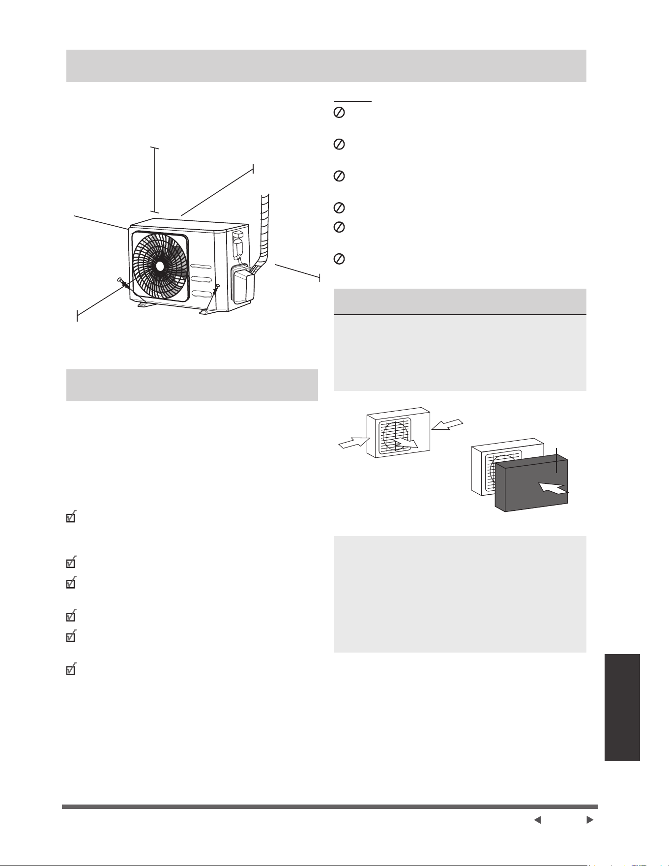
Page 27
Installation de
l’unité extérieure
Installation de l’unité extérieure
,QVWDOOH]O¶XQLWpHQVXLYDQWOHVFRGHVHWUqJOHPHQWV
locaux, il peut y avoir de légères différences entre
les différentes régions.
60cm (24 pouces)
dessus
30cm (12 pouces)
jJDXFKH
30cm (12 pouces)
GXPXUDUULqUH
FPSRXFHV
en avant
60cm (24 pouces)
à droite
Instructions d’installation - Unité
extérieure
eWDSH6pOHFWLRQQH]O¶HPSODFHPHQWG¶LQVWDOODWLRQ
$YDQWG¶LQVWDOOHUO¶XQLWpH[WpULHXUHYRXVGHYH]FKRLVLU
un emplacement approprié. Les normes suivantes
vous aideront à sélectionner un emplacement
DSSURSULpSRXUO¶XQLWp
L’emplacement approprié d’installation doit
répondre aux normes suivantes :
5pSRQGUHjWRXWHVOHVH[LJHQFHVVSDWLDOHV
indiquées dans la section Espace requis pour
O¶LQVWDOODWLRQFLGHVVXV
%RQQHFLUFXODWLRQG¶DLUHWYHQWLODWLRQ
)HUPHHWVROLGH²O¶HPSODFHPHQWSHXWVXSSRUWHU
O¶XQLWpHWQHYLEUHUDSDV
/HEUXLWGHO¶XQLWpQHGpUDQJHUDSDVOHVDXWUHV
3URWpJpFRQWUHOHVORQJXHVSpULRGHVGHOXPLqUH
directe du soleil ou de pluie
/RUVTXHGHVFKXWHVGHQHLJHVRQWSUpYXHVSUHQH]
les mesures appropriées pour éviter l'accumulation
GHJODFHHWOHVGRPPDJHVDX[VHUSHQWLQV
NE PAS installer l’unité dans les endroits suivants:
3UqVG¶XQREVWDFOHTXLEORTXHUDOHVHQWUpHVHWOHV
VRUWLHVG¶DLU
3UqVG¶XQHUXHSXEOLTXHGDQVGHVHQGURLWVERQGpV
RXORUVTXHOHEUXLWGHO¶XQLWpGpUDQJHOHVDXWUHV
3UqVG¶DQLPDX[RXGHSODQWHVTXLVHURQW
HQGRPPDJpVSDUODGpFKDUJHG¶DLUFKDXG
3UqVGHWRXWHVRXUFHGHJD]FRPEXVWLEOH
'DQVXQHQGURLWH[SRVpjGHJUDQGHVTXDQWLWpVGH
SRXVVLqUH
'DQVXQHQGURLWH[SRVpjXQHTXDQWLWpH[FHVVLYH
G¶DLUVDOp
&216,'e5$7,21663e&,$/(63285/(7(036
EXTRÊME
6LO¶XQLWpHVWH[SRVpHjXQYHQWIRUW
,QVWDOOH]O¶XQLWpGHVRUWHTXHO¶H[WUDFWHXUG¶DLUVRLWj
XQDQJOHGHSDUUDSSRUWDXYHQW6LQpFHVVDLUH
LQVWDOOH]XQHEDUULqUHGHYDQWO¶XQLWpSRXUOHSURWpJHU
GHVYHQWVH[WUrPHPHQWYLROHQWV
9RLUOHV¿JXUHVFLGHVVRXV
Vent fort
Vent fort
'pÀHFWHXU
de vent
Vent fort
6LO¶XQLWpHVWIUpTXHPPHQWH[SRVpHjGHIRUWHV
SOXLHVRXjODQHLJH
&RQVWUXLVH]XQDEULDXGHVVXVGHO¶XQLWpSRXUOD
SURWpJHUGHODSOXLHRXGHODQHLJH9HLOOH]jQHSDV
REVWUXHUOHÀX[G¶DLUDXWRXUGHO¶XQLWp
6LO¶XQLWpHVWIUpTXHPPHQWH[SRVpHjO¶DLUVDOp
ERUGGHODPHU
8WLOLVH]O¶XQLWpH[WpULHXUHVSpFLDOHPHQWFRQoXHSRXU
résister à la corrosion.
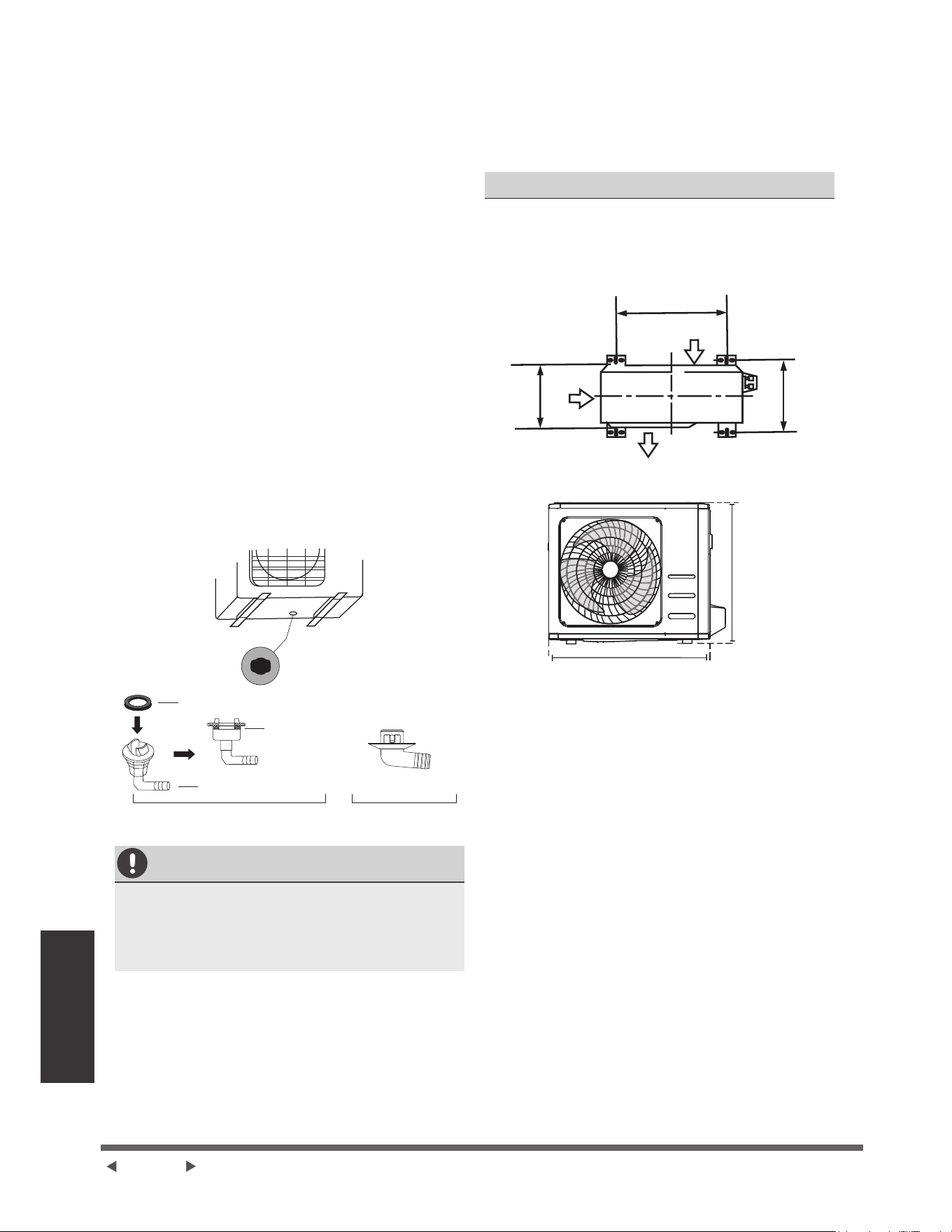
Page 28
Installation de
l'unité extérieure
Étape 2 : Installez le joint de drainage (appareil de
pompe à chaleur uniquement)
$YDQWGHYLVVHUOXQLWpH[WpULHXUHHQSODFHYRXV
GHYH]LQVWDOOHUOHMRLQWGHGUDLQDJHDXEDVGHODSSDUHLO
,OIDXWQRWHUTXLOH[LVWHGHX[W\SHVGLႇpUHQWVGHMRLQWV
GHGUDLQDJHHQIRQFWLRQGXW\SHGXQLWpH[WpULHXUH
Si le joint de drainage est livré avec un joint en
caoutchouc (¿JXUH$SURFpGHUFRPPHVXLW
,QVWDOOH]OHMRLQWHQFDRXWFKRXFjOH[WUpPLWpGX
MRLQWGHGUDLQDJHTXLVHFRQQHFWHUDjOXQLWp
H[WpULHXUH
,QVpUH]OHMRLQWGHGUDLQDJHGDQVOHWURXGX
SODWHDXLQIpULHXUGHODSSDUHLO
)DLWHVSLYRWHUOHMRLQWGHYLGDQJHGHMXVTXj
FHTXLOVHQFOHQFKHHQSODFHIDFHjODYDQWGH
ODSSDUHLO
&RQQHFWH]XQHUDOORQJHGHWX\DXGHGUDLQDJH
QRQIRXUQLHDXMRLQWGHGUDLQDJHSRXUUHGLULJHU
OHDXGHODSSDUHLOHQPRGHGHFKDXႇDJH
Si le joint de drainage ne vient pas avec un joint
en caoutchouc (Fig. BSURFpGH]FRPPHVXLW
,QVpUH]OHMRLQWGHGUDLQDJHGDQVOHWURXGXSODWHDX
LQIpULHXUGHODSSDUHLO/HMRLQWGHGUDLQDJHHVW
FRLQFpHQSODFH
5DFFRUGH]XQHUDOORQJHGHWX\DXGHYLGDQJHQRQ
LQFOXVHDXUDFFRUGGHYLGDQJHSRXUUHGLULJHUOHDX
GHODSSDUHLOHQPRGHFKDXႇDJH
Trou du plateau inférieur
GHO¶XQLWpH[WpULHXUH
Joint
Joint
Joint de drainage
(A) (B)
SOUS CLIMAT FROID
6RXVFOLPDWIURLGDVVXUH]YRXVTXHOHWX\DXGH
GUDLQDJHHVWDXVVLYHUWLFDOTXHSRVVLEOHSRXUDVVXUHU
XQGUDLQDJHUDSLGHGHO¶HDX6LOHDXVpFRXOHWURS
lentement, elle peut geler dans le tuyau et inonder
ODSSDUHLO
Étape 3 : Ancrage de l'unité intérieure
/XQLWpH[WpULHXUHSHXWrWUHDQFUpHDXVRORXj
XQVXSSRUWPXUDODYHFERXORQ03UpSDUH]OD
EDVHG¶LQVWDOODWLRQGHO¶DSSDUHLOFRQIRUPpPHQWDX[
GLPHQVLRQVFLGHVVRXV
DIMENSIONS DE MONTAGE DE L’APPAREIL
9RXVWURXYHUH]FLGHVVRXVXQHOLVWHGHVGLႇpUHQWHV
GLPHQVLRQVG¶XQLWpVH[WpULHXUHVHWGHODGLVWDQFH
HQWUHOHXUVSLHGVGHPRQWDJH3UpSDUH]ODEDVH
G¶LQVWDOODWLRQGHO¶XQLWpFRQIRUPpPHQWDX[GLPHQVLRQV
FLFLGHVVR
A
D
B
Entrée d’air
Entrée
d’air
Sortie d’air
H
W
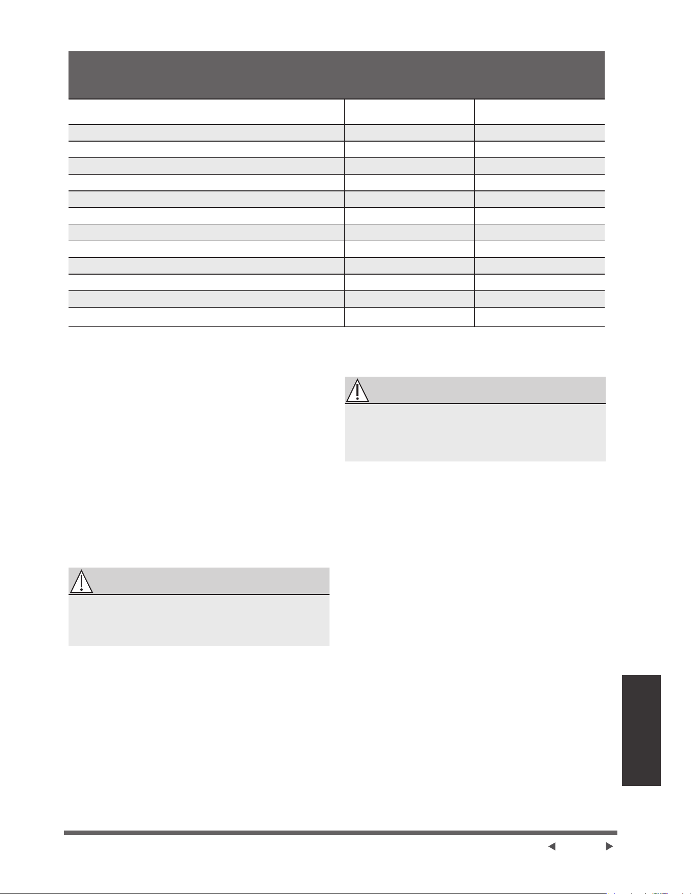
Page 29
Installation de
l'unité extérieure
'LPHQVLRQVGHOXQLWpH[WpULHXUHPP:î+ î'
DIMENSIONS
'(0217$*(
'LVWDQFH$PP 'LVWDQFH%PP
îî´î´î´ ´ ´
îî´î´î´ ´ ´
îî´î´î´ ´ ´
îî´î´î´ ´ ´
îî´î´î´ ´ ´
îî´î´î´ ´ ´
îî´î´î´ ´ ´
îî´î´î´ ´ ´
îî´î´î´ ´ ´
îî´î´î´ ´ ´
îî´î´î´ ´ ´
îî´î´î´ ´ ´
îî´î´î´ ´ ´
6LYRXVVRXKDLWH]LQVWDOOHUODSSDUHLOVXUOHVRORX
VXUXQHSODWHIRUPHGHPRQWDJHHQEpWRQSURFpGH]
FRPPHVXLW
1. 0DUTXH]OHVSRVLWLRQVSRXUTXDWUHERXORQV
GH[SDQVLRQHQIRQFWLRQGXSODQGHVGLPHQVLRQV
2. 3UpSHUFH]GHVWURXVSRXUOHVERXORQVGH[SDQVLRQ
3. 3ODFH]XQpFURXjOD¿QGHFKDTXHERXORQ
GH[SDQVLRQ
4. 0DUWHOH]OHVERXORQVGH[SDQVLRQGDQVOHVWURXV
SUpSHUFpV
5. 5HWLUH]OHVpFURXVGHVERXORQVGH[SDQVLRQHW
SODFHUOXQLWpH[WpULHXUHVXUOHVERXORQV
6. 0HWWH]ODURQGHOOHVXUFKDTXHERXORQG¶H[SDQVLRQ
puis remplacez les écrous.
7. ¬ODLGHGXQHFOpVHUUH]FKDTXHpFURXMXVTXjFH
TXLOVRLWELHQDMXVWp
AVERTISSEMENT
LA PROTECTION DES YEUX EST
RECOMMANDÉE
EN TOUT TEMPS
/256'8)25$*('$16/(%e721
6LYRXVVRXKDLWH]LQVWDOOHUO¶DSSDUHLOVXUXQVXSSRUW
PXUDOSURFpGH]FRPPHVXLW
ATTENTION
$VVXUH]YRXVTXHOHPXUHVWHQEULTXHVROLGHHQ
EpWRQRXHQXQPDWpULDXGHUpVLVWDQFHVLPLODLUH Le
PXUGRLWSRXYRLUVXSSRUWHUDXPRLQVTXDWUHIRLVOH
poids de l'appareil.
1. 0DUTXH]ODSRVLWLRQGHVWURXVGH¿[DWLRQHQYRXV
EDVDQWVXUOHWDEOHDXGHVGLPHQVLRQV
2. 3UpSHUFH]OHVWURXVSRXUOHVERXORQVGH[SDQVLRQ
3. 3ODFH]XQHURQGHOOHHWXQpFURXjOD¿QGHFKDTXH
ERXORQjH[SDQVLRQ
4. 9LVVH]OHVERXORQVGHGLODWDWLRQjWUDYHUVOHVWURXV
GHVVXSSRUWVGH¿[DWLRQPHWWH]OHVHQSODFHHW
HQIRQFH]OHVERXORQVGHGLODWDWLRQGDQVOHPXU
5. 9pUL¿H]TXHOHVVXSSRUWVGHPRQWDJHVRQWSODQV
6. 6RXOHYH]VRLJQHXVHPHQWO¶DSSDUHLOHWSODFHUVHV
SLHGVGHPRQWDJHVXUGHVVXSSRUWV
7. %RXORQQH]IHUPHPHQWO¶DSSDUHLODX[VXSSRUWV
8. 6LFHODHVWDXWRULVpLQVWDOOH]ODSSDUHLODYHFGHV
MRLQWVHQFDRXWFKRXFSRXUUpGXLUHOHVYLEUDWLRQVHW
OHEUXLW
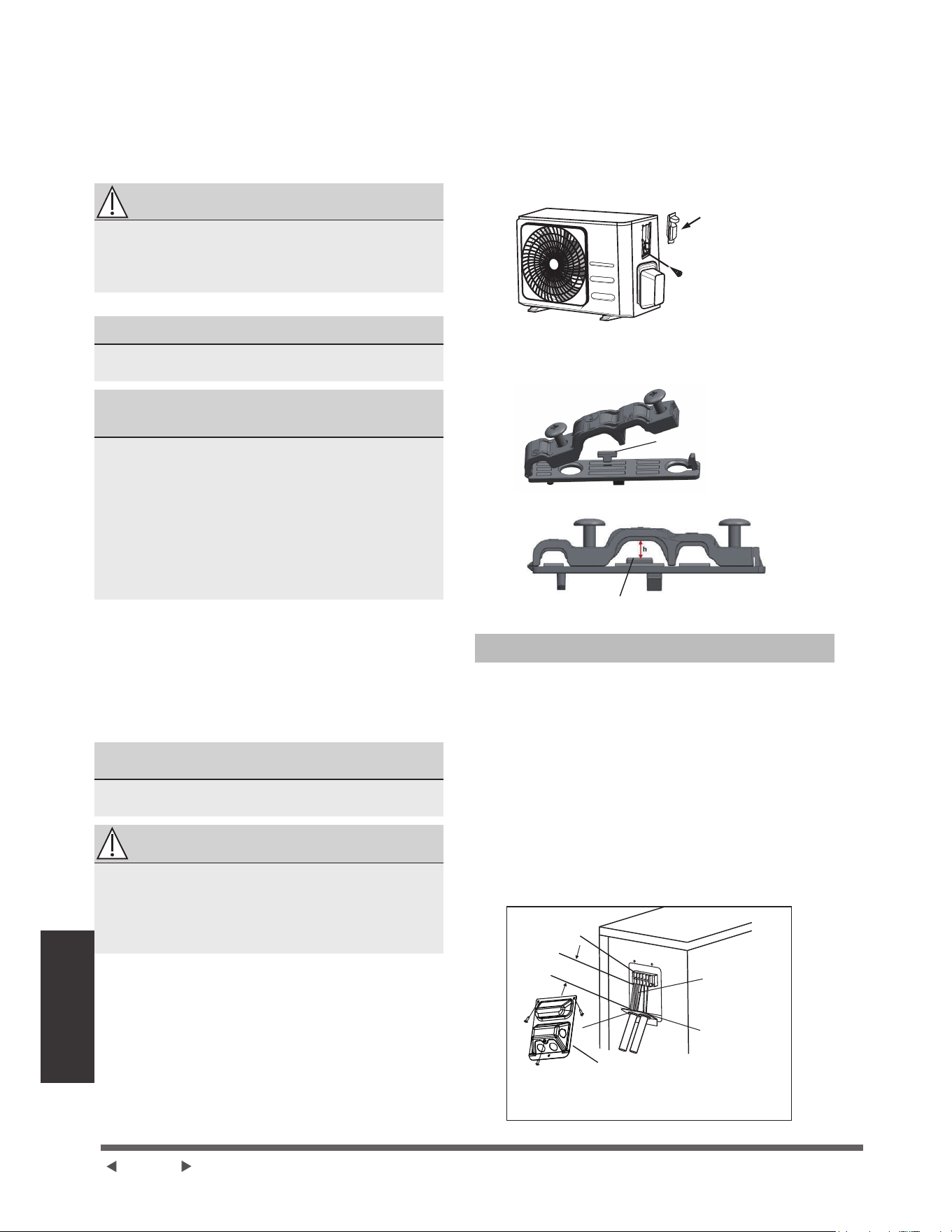
Page 30
Installation de
l’unité extérieure
eWDSH&RQQHFWH]OHVFkEOHVGHVLJQDOHW
d’alimentation.
/HERUQLHUGHOXQLWpH[WpULHXUHHVWSURWpJpSDUXQ
FRXYHUFOHGHFkEODJHpOHFWULTXHVXUOHF{WpGHOXQLWp
/HVFKpPDGHFkEODJHFRPSOHWHVWLPSULPpj
O¶LQWpULHXUGXFRXYHUFOHGHFkEODJH
AVERTISSEMENT
AVANT LA MISE EN OEUVRE DE TOUT TRAVAIL
e/(&75,48(28'(&Æ%/$*(9(8,//(=
&283(5/¶$/,0(17$7,2135,1&,3$/('8
SYSTÈME.
1. 3UpSDUH]OHFkEOHSRXUODFRQQH[LRQ
87,/,6(=/(&Æ%/(&255(&7
9HXLOOH]FKRLVLUOHERQFkEOHYRLU©7\SHVGH
FkEOHVªjODSDJH
&+2,6,5/$%211(7$,//('8
&$%/(
/DWDLOOHGXFkEOHG¶DOLPHQWDWLRQGXFkEOHGH
VLJQDOGXIXVLEOHHWGXFRPPXWDWHXUQpFHVVDLUHV
HVWGpWHUPLQpHSDUOHFRXUDQWPD[LPDOGHO¶XQLWp
/HFRXUDQWPD[LPXPHVWLQGLTXpVXUODSODTXH
VLJQDOpWLTXHVLWXpHVXUOHSDQQHDXODWpUDOGHO¶XQLWp
NOTE :(Q$PpULTXHGX1RUGYHXLOOH]FKRLVLU
ODERQQHWDLOOHGHFkEOHHQIRQFWLRQGHO¶LQWHQVLWp
minimale du circuit indiquée sur la plaque
VLJQDOpWLTXHGHO¶XQLWp
D ¬ODLGHGXQHSLQFHjGpQXGHUGpQXGH]ODJDLQH
HQFDRXWFKRXFGHVGHX[H[WUpPLWpVGXFkEOHSRXU
ODLVVHUDSSDUDvWUHHQYLURQPPSRGH¿OV
à l'intérieur.
E 'pQXGH]O¶LVRODWLRQGHVH[WUpPLWpVGHVFkEOHV
F ¬O¶DLGHG¶XQHSLQFHjVHUWLUOHV¿OVVHUWLVVH]GHV
SDWWHVHQ8DX[H[WUpPLWpVGHVFkEOHV
)$,7(6$77(17,21$8;&$%/(66286
TENSION
/RUVTXHYRXVVHUWLVVH]GHV¿OVYHLOOH]jGLVWLQJXHU
FODLUHPHQWOH¿OVRXVWHQVLRQ©/ªGHVDXWUHV¿OV
AVERTISSEMENT
7286/(675$9$8;'(&Æ%/$*('2,9(17
Ç75(())(&78e6(15(63(&7$17
675,&7(0(17/(6&+e0$'(&Æ%/$*(
6,78e¬/,17e5,(85'8&289(5&/('(6
),/6'(/81,7e(;7e5,(85(
2. 'pYLVVH]OHFRXYHUFOHGXFkEODJHpOHFWULTXHHWOH
retirez.
3. 'pYLVVH]OHVHUUHFkEOHVRXVODERvWHjERUQHHWOH
SODFH]VXUOHF{Wp
4. &RQQHFWH]OHFkEOHFRQIRUPpPHQWDXVFKpPD
GHFkEODJHHWYLVVH]IHUPHPHQWODSDWWHHQ
8GH¿[DWLRQGHFKDTXHFkEOHDXWHUPLQDO
correspondant.
5. $SUqVDYRLUYpUL¿pTXHFKDTXHFRQQH[LRQHVW
VpFXULVpHERXFOH]OHVFkEOHVDXWRXUSRXU
HPSrFKHUO¶HDXGHSOXLHGHV¶pFRXOHUGDQVOH
terminal.
6. ¬O¶DLGHGXVHUUHFkEOH¿[H]OHFkEOHjO¶XQLWp
9LVVH]IHUPHPHQWOHVHUUHFkEOH
7. ,VROH]OHVFkEOHVQRQXWLOLVpVDYHFGXUXEDQ
pOHFWULTXH39&'LVSRVH]OHVGHPDQLqUHjFH
TX¶HOOHVQHWRXFKHQWDXFXQHSLqFHpOHFWULTXHRX
métallique.
8. 5HSODFH]OHFRXYHUFOHGXFkEOHVXUOHF{WpGHO¶XQLWp
et le vissez en place.
Couvercle
Vis
NOTE :6LOHVHUUHFkEOHUHVVHPEOHjFHTXLVXLW
YHXLOOH]VpOHFWLRQQHUOHWURXGHSDVVDJHDSSURSULpHQ
IRQFWLRQGXGLDPqWUHGX¿O
%RXFOHGH¿[DWLRQ
Trou de trois tailles : Petite, grande,
moyenne
/RUVTXHOHFkEOHQHVWSDVDVVH]VHUUpXWLOLVH]ODERXFOHGH
¿[DWLRQSRXUOHPDLQWHQLUHQSODFHD¿QTX¶LOSXLVVHrWUHELHQVHUUp
(Q$PpULTXHGX1RUG
1. 5HWLUH]OHFRXYHUWXUHGHFkEOHGHO¶XQLWpHQ
desserrant les 3 vis.
2. Démontez les capuchons sur le panneau de
conduit.
3. 0RQWH]SURYLVRLUHPHQWOHVWXEHVGHFRQGXLWQRQ
inclus) sur le panneau de conduit.
4. Connectez correctement l'alimentation
pOHFWULTXHHWOHVOLJQHVEDVVHWHQVLRQDX[ERUQHV
FRUUHVSRQGDQWHVGXERUQLHU
5. 0HWWH]O¶XQLWpjODWHUUHFRQIRUPpPHQWDX[FRGHV
ORFDX[
6. 9HLOOH]jGLPHQVLRQQHUFKDTXHFkEOHGHPDQLqUHj
FHTX¶LOGpSDVVHGHSOXVLHXUVSRXFHVODORQJXHXU
UHTXLVHSRXUOHFkEODJH
7. 8WLOLVH]GHVpFURXVGHEORFDJHSRXU¿[HUOHVWXEHV
de conduit.
%RvWHjERUQH
&kEOHGH
FRQQH[LRQ
Panneau de
conduit
&RXYHUWXUHGH¿O
9HXLOOH]VpOHFWLRQQHUOHWURXGHSDVVDJHDSSURSULp
VHORQOHGLDPqWUHGHFkEOH
6XSpULHXUHjSR
(40mm)
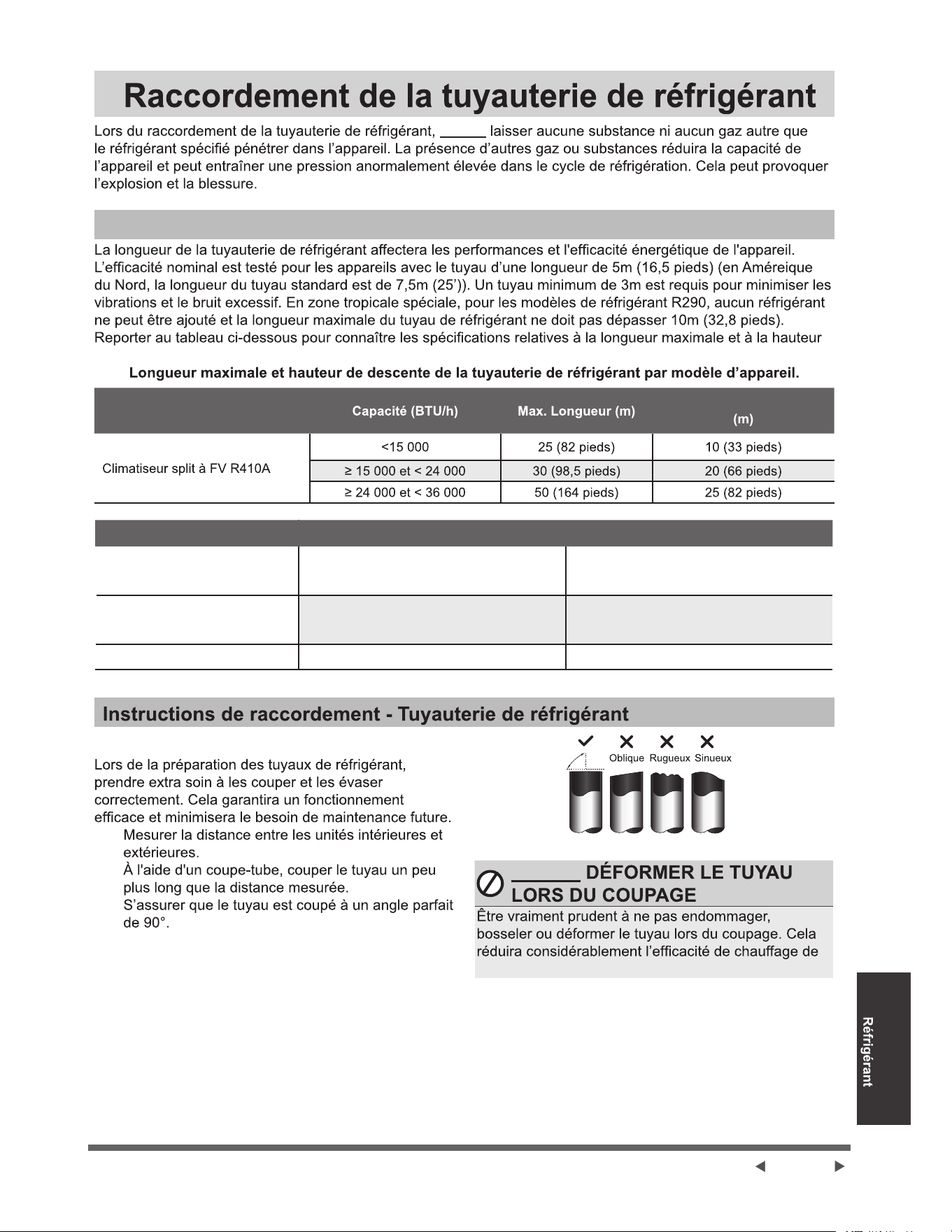
Page 31
Raccordement de
la Tuyauterie de
ne pas
Note sur la Longueur de Tuyau
de descente de la tuyauterie.
Modèle
Max. Hauteur de descente
Étape 1 : Couper des tuyaux
1.
2.
3.
90°
NE PAS
l’appareil.
MHWAL06DA/MHSZ106DA
MHWAL09DA/MHSZ109DA
Φ6.35(1/4in)
Φ6.35(1/4in)
Φ9.52(3/8in)
Φ9.52(3/8in)
Φ12.7(1/2in)
Φ16(5/8in)
MHWAL12DA/MHSZ112DA
MHWAL18DA/MHSZ118DA
MHWAL24DA/MHSZ124DA
ECR Modèle Côté liquide mm(in) Côté gaz mm(in)
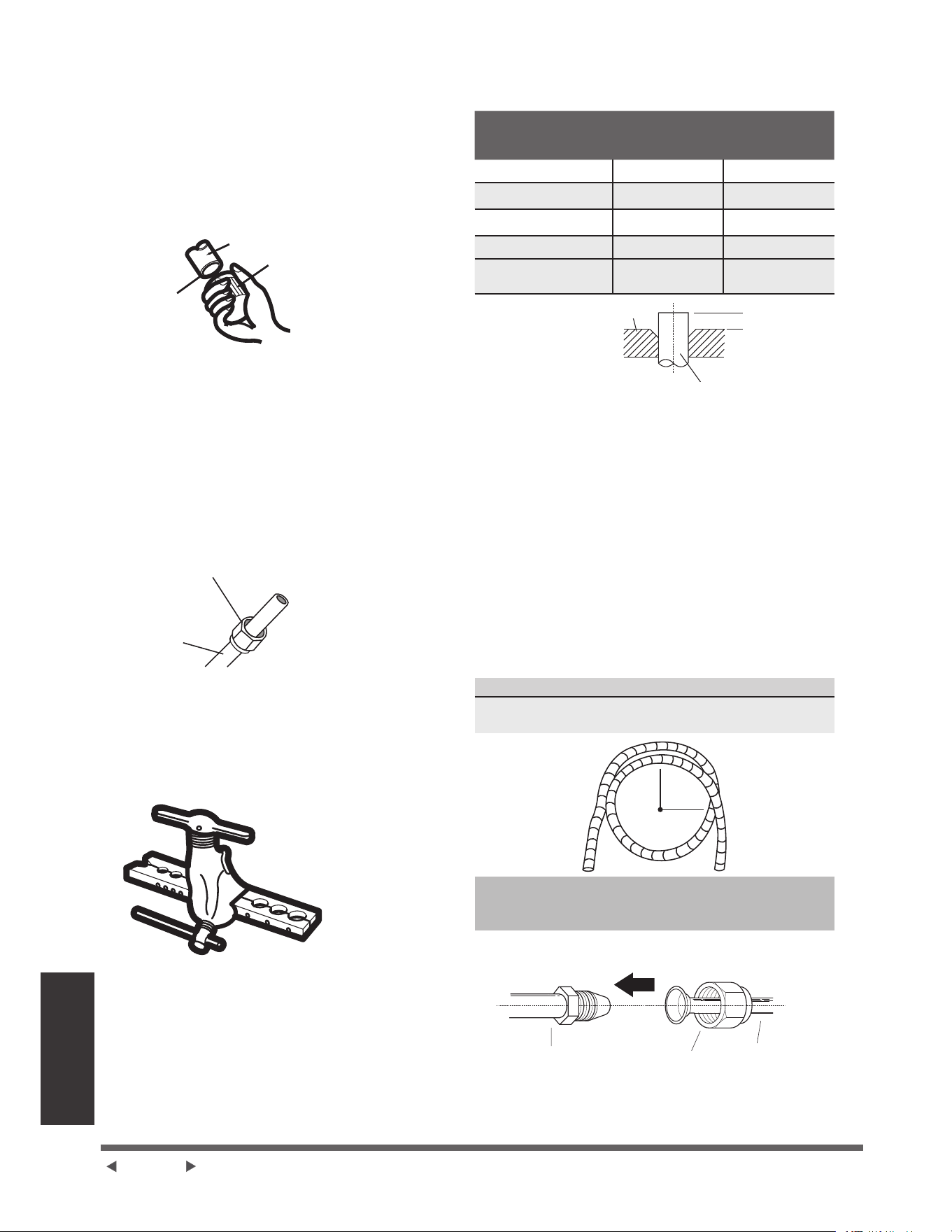
Page 32
Raccordement de
la Tuyauterie de
5pIULJpUDQW
Étape 2 : Enlever les bavures
/HVEDYXUHVSHXYHQWDIIHFWHUOHMRLQWpWDQFKHjO¶DLU
GH5DFFRUGHPHQWGHOD7X\DXWHULHGH5pIULJpUDQW,OV
GRLYHQWrWUHFRPSOqWHPHQWHQOHYpV
1. 7HQLUOHWX\DXjXQDQJOHYHUVOHEDVSRXUpYLWHU
TXHGHVEDYXUHVQHWRPEHQWGDQVOHWX\DX
2. ¬ODLGHGXQDOpVRLURXGXQRXWLOGpEDYXUDJH
HQOHYHUWRXWHVOHVEDYXUHVGHODVHFWLRQFRXSpHGX
tuyau.
Tuyau
$OpVRLU
Pointer
YHUVOHEDV
Étape 3 : Évaser les extrémités des tuyaux
8QERQpYDVHPHQWHVWHVVHQWLHOSRXUREWHQLUOHMRLQW
étanche à l’air.
1. $SUqVDYRLUHQOHYpOHVEDYXUHVGXWX\DXFRXSp
VFHOOHUOHVH[WUpPLWpVDYHFGXUXEDQHQ39&SRXU
pYLWHUO¶HQWUpHGHVFRUSVpWUDQJHUVGDQVOHWX\DX
2. *DLQHUOHWX\DXDYHFXQPDWpULDXLVRODQW
3. 3ODFHUOHVpFURXVjHPEDVHDX[GHX[H[WUpPLWpV
GXWX\DX6¶DVVXUHUTXLOVVRQWGDQVODERQQH
GLUHFWLRQFDUYRXVQHSRXYH]SDVOHVPHWWUHRX
FKDQJHUOHXUGLUHFWLRQDSUqVOHVDYRLUpYDVpV
eFURXjHPEDVH
Tuyau en
cuivre
4. (QOHYHUOHUXEDQHQ39&GHVH[WUpPLWpVGX
tuyau lorsque vous êtes prêt à effectuer le travail
d’évasement.
5. )L[HUODIRUPHG¶pYDVHPHQWDXERXWGXWX\DX
/H[WUpPLWpGXWX\DXGRLWGpSDVVHUGXERUGGH
ODIRUPHSODWHFRQIRUPpPHQWDX[GLPHQVLRQV
LQGLTXpHVGDQVOHWDEOHDXFLGHVVRXV
(;7(16,21'(78<$87(5,($8'(/$'8)250(
D’EVASEMENT
Diamètre extérieur
GXWX\DXPP
$PP
Min. Max.
¡¡´ ´ ´
¡¡´ ´ ´
¡¡´ ´ ´
¡¡´ ´ ´
¡¡´ ´ ´
$
)RUPHG¶pYDVHPHQW
Tuyau
6. Placer l'outil d’évasement sur la forme.
7. 7RXUQHUODSRLJQpHGHORXWLOGpYDVHPHQWGDQVOH
VHQVGHVDLJXLOOHVGXQHPRQWUHMXVTXjFHTXHOH
WX\DXVRLWFRPSOqWHPHQWpYDVp
8. Enlever l’outil d’évasement et la forme
G¶pYDVHPHQWSXLVH[DPLQHUO¶H[WUpPLWpGX
WX\DXSRXU\GpFHOHUGHV¿VVXUHVHWPrPHXQ
évasement.
Étape 4 : Connecter des tuyaux
/RUVGXUDFFRUGHPHQWGHVWX\DX[GHUpIULJpUDQWYHLOOHU
jQHSDVXWLOLVHUODWRUTXHH[FHVVLYHQLjGpIRUPHUOH
WX\DXGHTXHOTXHPDQLqUHTXHFHVRLW9RXVGHYH]
G¶DERUGFRQQHFWHUOHWX\DXjEDVVHSUHVVLRQSXLVOH
tuyau à haute pression.
Rayon de courbure minimal
/RUVGXSOLDJHGXQHWX\DXWHULHGHUpIULJpUDQWFRQQHFWLI
OHUD\RQGHFRXUEXUHPLQLPDOHVWGHFP
Rayon
FPSRXFHV
Instructions pour connecter la
tuyauterie à l'unité intérieure
1. $OLJQHUOHFHQWUHGHVGHX[WX\DX[TXHYRXV
connecterez.
7XEXOXUHGHO¶XQLWp
intérieure
Écrou à
HPEDVH
Tuyau
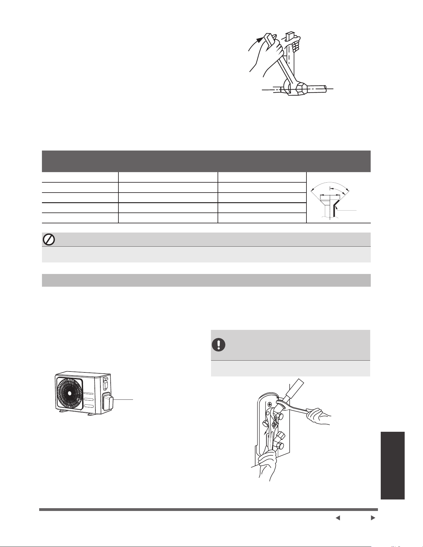
Page 33
Raccordement de
la Tuyauterie de
5pIULJpUDQW
2. 6HUUHUjODPDLQOpFURXjHPEDVHDXVVLIHUPHPHQW
TXHSRVVLEOH
3. ¬ODLGHGXQHFOpSLQFHUOpFURXVXUODWXEXOXUHGH
l'appareil.
4. 7RXWHQVHUUDQWIHUPHPHQWOpFURXVXUOHWXEH
GHODSSDUHLOXWLOLVHUXQHFOpG\QDPRPpWULTXH
SRXUVHUUHUOpFURXjHPEDVHFRQIRUPpPHQWDX[
YDOHXUVGHWRUTXHLQGLTXpHVGDQVOHWDEOHDXGHV
Exigences de torqueFLGHVVRXV'HVVHUUHU
OpJqUHPHQWOpFURXpYDVpSXLVUHVVHUUHUj
nouveau.
1. 'pYLVVHUOHFRXYHUFOHGHODYDQQHjJDUQLWXUHVXU
OHF{WpGHOXQLWpH[WpULHXUH
2. Enlever les capuchons de protection des
H[WUpPLWpVGHVYDQQHV
3. $OLJQHUOH[WUpPLWpGXWX\DXG¶pYDVHPHQWDYHF
FKDTXHYDQQHHWVHUUHUOpFURXjHPEDVHDXVVL
IHUPHPHQWTXHSRVVLEOHjODPDLQ
4. ¬ODLGHGXQHFOpSLQFHUOHFRUSVGHODYDQQH1H
pas pincer l’écrou qui ferme la vanne de service.
Couvercle de vanne
5. 7RXWHQWHQDQWIHUPHPHQWOHFRUSVGHODYDQQH
VHUUHUO¶pFURXjHPEDVHjO¶DLGHG¶XQHFOpGHWRUTXH
en fonction des valeurs de torque correctes.
6. 'HVVHUUHUOpJqUHPHQWOpFURXpYDVpSXLVUHVVHUUHU
à nouveau.
7. Répéter les étapes 3 à 6 pour le tuyau restant.
UTILISER LA CLÉ POUR PINCER
LE CORPS PRINCIPAL DE LA
VANNE
/DWRUTXHSRXUOHVHUUDJHGHOpFURXjHPEDVHSHXW
détacher d'autres parties de la vanne.
(;,*(1&(6'(72548(
Diamètre extérieur du
WX\DXPP
&RXSOHGHVHUUDJH1P
Dimension d’évasement
%PP
)RUPH
d’évasement
¡¡´ NJIFP ´
5
45°±2
90°±4
B
¡¡´ NJIFP ´
¡¡´ NJIFP ´
¡¡´ NJIFP ´
¡¡´ NJIFP ´
NE PAS UTILISER LA TORQUE EXCESSIVE
8QHIRUFHH[FHVVLYHSHXWFDVVHUOpFURXRXHQGRPPDJHUODWX\DXWHULHGHUpIULJpUDQW9RXVQHGHYH]SDV
GpSDVVHUOHVH[LJHQFHVGHWRUTXHLQGLTXpHVGDQVOHWDEOHDXFLGHVVXV
Instructions pour connecter la tuyauterie à l'unité extérieure
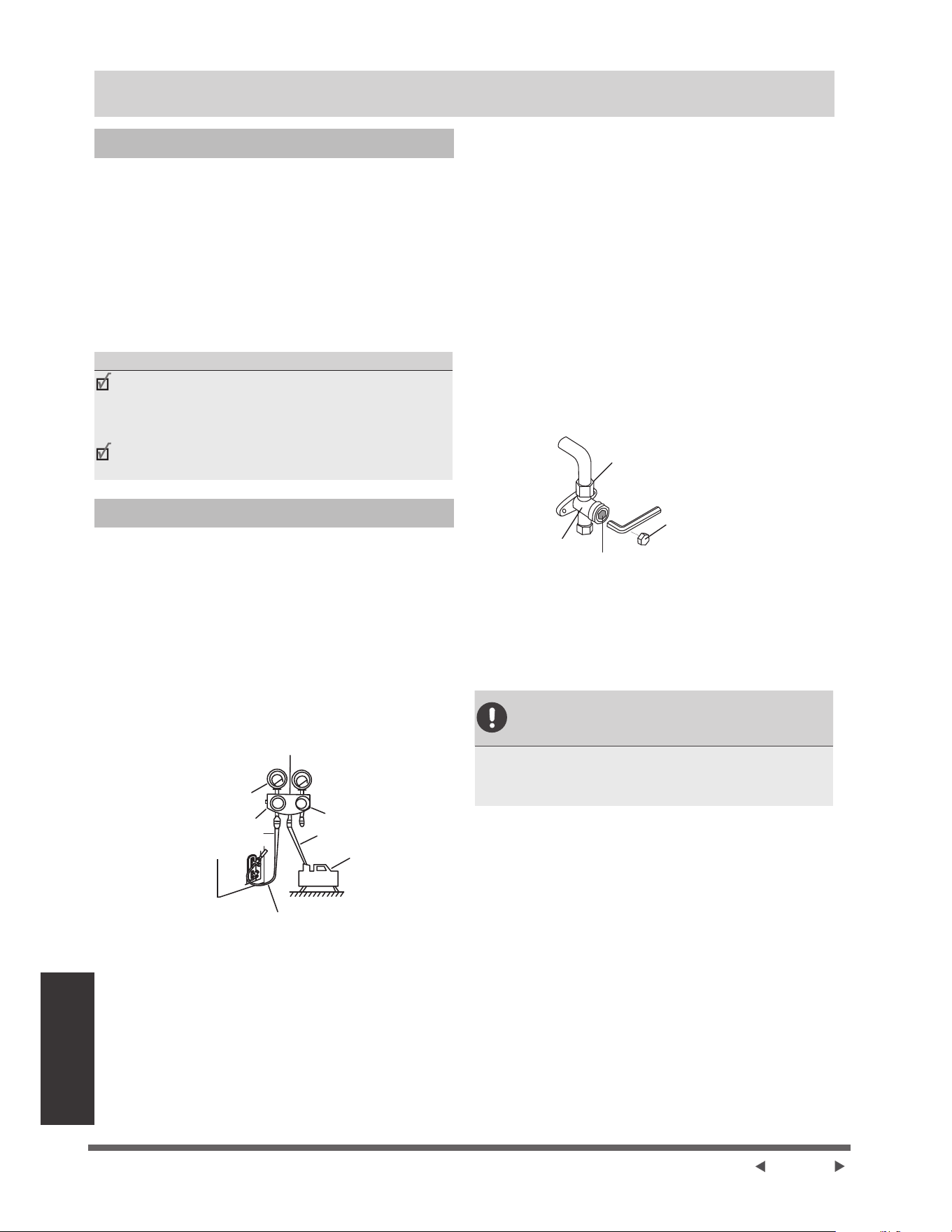
Page 3
Évacuation d'air
Évacuation d'air
Préparation et précaution
/¶DLUHWGHVFRUSVpWUDQJHUVGDQVOHFLUFXLWGHUpIULJpUDQW
SHXYHQWSURYRTXHUXQHDXJPHQWDWLRQDQRUPDOHGH
ODSUHVVLRQFHTXLSHXWHQGRPPDJHUOHFOLPDWLVHXU
UpGXLUHVRQHI¿FDFLWpHWFDXVHUGHVEOHVVXUHV 8WLOLVH]
XQHSRPSHjYLGHHWXQPDQRPqWUHGHFROOHFWHXUSRXU
pYDFXHUOHFLUFXLWGHUpIULJpUDQWHQpOLPLQDQWWRXWJD]
QRQFRQGHQVDEOHHWWRXWHKXPLGLWpGXV\VWqPH
L'évacuation doit être effectuée lors de l'installation
initiale et lorsque l'appareil est déplacé.
$9$17'¶())(&78(5/¶e9$&8$7,21
9pUL¿H]OHVWX\DX[GHFRQQH[LRQHQWUHOHVXQLWpV
LQWpULHXUHHWH[WpULHXUHSRXUDVVXUHTX¶LOVVRQW
correctement connectés.
$VVXUH]YRXVTXHWRXWOHFkEODJHHVWFRUUHFWHPHQW
connecté.
Instructions d'évacuation
1. &RQQHFWH]OHWX\DXGHFKDUJHGXPDQRPqWUHGH
FROOHFWHXUDXSRUWG¶HQWUHWLHQGHODYDQQHGHEDVVH
SUHVVLRQGHOXQLWpH[WpULHXUH
2. &RQQHFWH]XQDXWUHWX\DXGHFKDUJHGXPDQRPqWUH
de collecteur à la pompe à vide.
3. 2XYUH]OHF{Wpj%DVVH3UHVVLRQGXPDQRPqWUHGH
FROOHFWHXU*DUGH]OHF{Wpj+DXWH3UHVVLRQIHUPp
4. 'pPDUUH]ODSRPSHjYLGHSRXUpYDFXHUOHV\VWqPH
5. )DLWHVIRQFWLRQQHUjYLGHSHQGDQWDXPRLQVGH
PLQXWHVRXMXVTXjFHTXHOHGpELWPqWUHFRPSRVp
LQGLTXHFP+*
5
3D
0DQRPqWUHGHFROOHFWHXU
-DXJHFRPSRVpH
FP+J
9DQQHjEDVVHSUHVVLRQ
7X\DXGHSUHVVLRQ
Vanne à haute pression
0DQRPqWUH
7X\DXGHFKDUJH
Pompe à vide
7X\DXGHFKDUJH
9DQQHjEDVVHSUHVVLRQ
6. )HUPH]OHF{Wpj%DVVHSUHVVLRQGXPDQRPqWUHGH
collecteur et arrêtez la pompe à vide.
7. $WWHQGH]PLQXWHVSXLVYpUL¿H]TXLOQ\DSDVHX
GHFKDQJHPHQWGDQVODSUHVVLRQGXV\VWqPH
8. 6LODSUHVVLRQGXV\VWqPHFKDQJHFRQVXOWH]OD
VHFWLRQ9pUL¿FDWLRQGHVIXLWHVGHJD]SRXUVDYRLU
FRPPHQWYpUL¿HUOHVIXLWHV6LOQ\DSDVGH
FKDQJHPHQWGHSUHVVLRQGDQVOHV\VWqPHGpYLVVHU
OHFDSXFKRQGHODYDQQHjJDUQLWXUHYDQQHjKDXWH
SUHVVLRQ
9. ,QVpUH]XQHFOpKH[DJRQDOHGDQVODYDQQHj
JDUQLWXUHYDQQHKDXWHSUHVVLRQHWRXYUH]ODYDQQH
en tournant la clé d'un quart de tour dans le sens
LQYHUVHGHVDLJXLOOHVGXQHPRQWUHeFRXWH]VLGX
JD]VRUWGXV\VWqPHSXLVIHUPH]ODYDQQHDXERXW
de 5 secondes.
10. 2EVHUYH]OH0DQRPqWUHSHQGDQWXQHPLQXWH
SRXUDVVXUHUTXLOQ\DSDVGHFKDQJHPHQWGH
SUHVVLRQ/HPDQRPqWUHGRLWLQGLTXHUXQHSUHVVLRQ
OpJqUHPHQWVXSpULHXUHjODSUHVVLRQDWPRVSKpULTXH
11. (QOHYH]OHWX\DXGHFKDUJHGXSRUWG¶HQWUHWLHQ
eFURXjHPEDVH
7LJHGHYDQQH
Corps de
vanne
Capuchon
12. ¬ODLGHGXQHFOpKH[DJRQDOHRXYUH]FRPSOqWHPHQW
OHVYDQQHVjKDXWHSUHVVLRQHWjEDVVHSUHVVLRQ
13. 6HUUH]jODPDLQOHVERXFKRQVGHVWURLVVRXSDSHV
RUL¿FHGHVHUYLFHKDXWHSUHVVLRQEDVVHSUHVVLRQ
9RXVSRXYH]OHVHUUHUGDYDQWDJHjODLGHGXQHFOp
dynamométrique si nécessaire.
OUVRIR DÉLICATEMENT '(7,*(
DE VANNE
/RUVTXHYRXVRXYUH]OHVWLJHVGHYDQQHWRXUQH]ODFOp
KH[DJRQDOHMXVTXjFHTXHOOHIUDSSHOHERXFKRQ 1H
SDVHVVD\HUGHIRUFHUODYDQQHjO¶RXYULUGDYDQWDJH
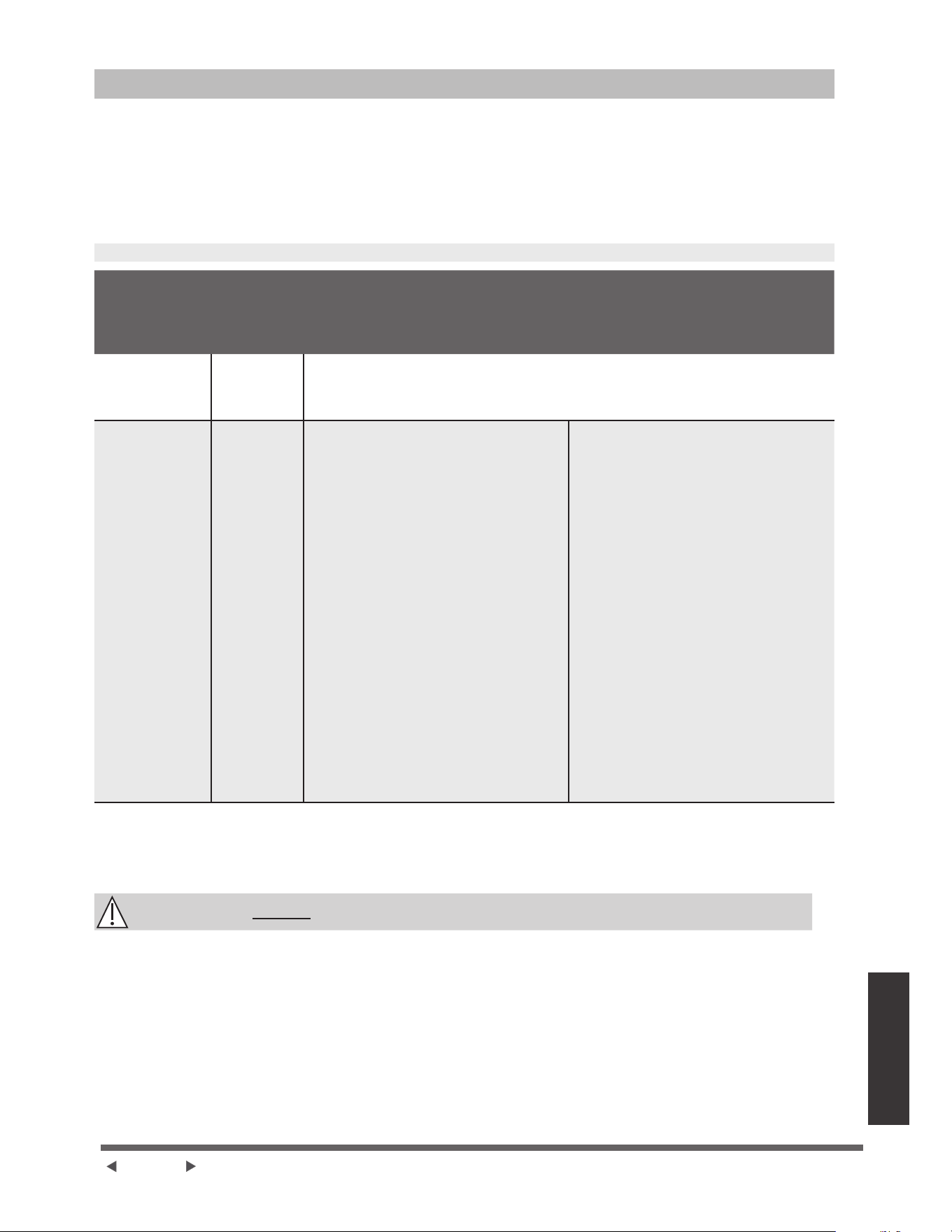
Page 3
Évacuation d'air
1RWHUHODWLYHjO¶DMRXWGHUpIULJpUDQW
&HUWDLQVV\VWqPHVQpFHVVLWHQWXQHFKDUJHVXSSOpPHQWDLUHHQIRQFWLRQGHODORQJXHXUGXWX\DX /DORQJXHXU
VWDQGDUGGXWX\DXYDULHHQIRQFWLRQGHODUpJOHPHQWDWLRQORFDOH 3DUH[HPSOHHQ$PpULTXHGX1RUGODORQJXHXU
VWDQGDUGGHVWX\DX[HVWGHP
'DQVOHVDXWUHV]RQHVODORQJXHXUVWDQGDUGGXWX\DXHVWGHP /HUpIULJpUDQWGRLWrWUHFKDUJpjSDUWLUGX
SRUWG¶HQWUHWLHQVLWXpVXUODYDQQHjEDVVHSUHVVLRQGHOXQLWpH[WpULHXUH /HUpIULJpUDQWVXSSOpPHQWDLUHjFKDUJHU
SHXWrWUHFDOFXOpjODLGHGHODIRUPXOHVXLYDQWH
5e)5,*e5$176833/e0(17$,5(3$5/21*8(85'(78<$8
Longueur
du tuyau de
raccordement
P
0pWKRGHGH
purge
d'air
5pIULJpUDQW
supplémentaire
ORQJXHXU
standard du
tuyau
Pompe à
vide
1$
!ORQJXHXU
standard du
tuyau
Pompe à
vide
&{WpOLTXLGH¡¡´
R32 :
/RQJXHXUGXWX\DXORQJXHXUVWDQGDUG
îJP
/RQJXHXUGXWX\DXORQJXHXUVWDQGDUG
îR=SLHG
R290 :
/RQJXHXUGXWX\DXORQJXHXUVWDQGDUG
[JP
/RQJXHXUGHWX\DXORQJXHXUVWDQGDUG
[R=SLHG
R410A :
/RQJXHXUGXWX\DXORQJXHXUVWDQGDUG
îJP
/RQJXHXUGXWX\DXORQJXHXUVWDQGDUG
îR]SLHG
R22 :
/RQJXHXUGXWX\DXORQJXHXUVWDQGDUG
[JP
/RQJXHXUGHWX\DXORQJXHXUVWDQGDUG
[R=SLHG
&{WpOLTXLGH¡¡´
R32 :
/RQJXHXUGXWX\DXORQJXHXUVWDQGDUG
[JP
/RQJXHXUGHWX\DXORQJXHXUVWDQGDUG
[R=SLHG
R290 :
/RQJXHXUGXWX\DXORQJXHXUVWDQGDUG
[JP
/RQJXHXUGXWX\DXORQJXHXUVWDQGDUG
[R=SLHG
R410A :
/RQJXHXUGXWX\DXORQJXHXUVWDQGDUG
[JP
/RQJXHXUGHWX\DXORQJXHXUVWDQGDUG
[R=SLHG
R22 :
/RQJXHXUGXWX\DXORQJXHXUVWDQGDUG
[JP
/RQJXHXUGHWX\DXORQJXHXUVWDQGDUG
[R=SLHG
3RXUODSSDUHLOGHUpIULJpUDQW5ODTXDQWLWpWRWDOHGHUpIULJpUDQWjFKDUJHUQHGpSDVVHSDV
J %WXKJ!%WXKHW %WXKJ!%WXKHW %WXKJ!%WXK
HW %WXK
ATTENTION
NE PAS PpODQJHUOHVW\SHVGHUpIULJpUDQWV
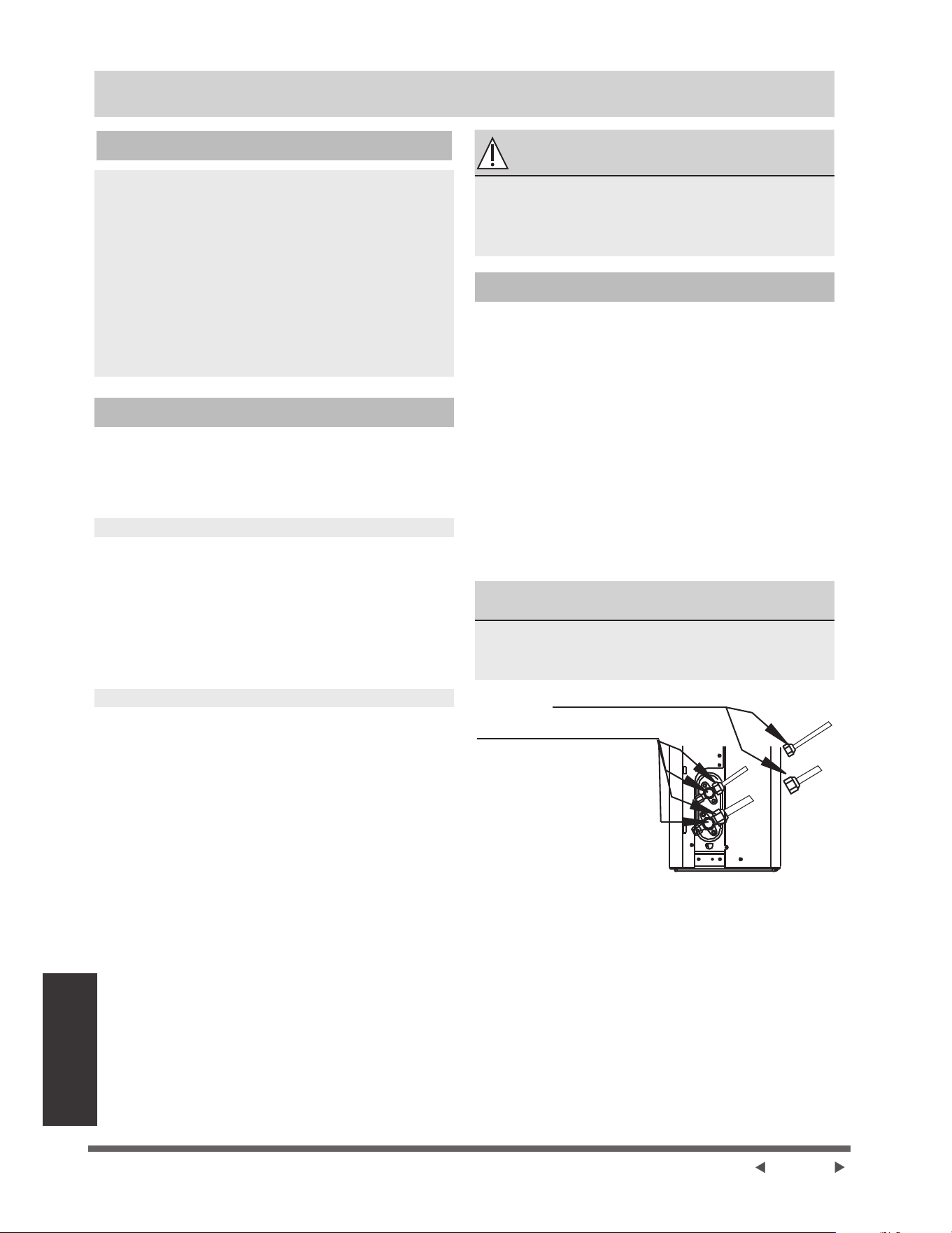
Page 3
9pUL¿FDWLRQGHV
IXLWHVGHJD]HW
d’électricité
9pUL¿FDWLRQGHVIXLWHVGHJD]HWG¶pOHFWULFLWp
Avant la mise en service
1HIIHFWXH]ODPLVHHQVHUYLFHTXDSUqVDYRLUVXLYLOHV
pWDSHVVXLYDQWHV
Ɣ Contrôles de sécurité électrique&RQ¿UPH]
TXHOHV\VWqPHpOHFWULTXHGHODSSDUHLOHVWVUHW
fonctionne correctement
Ɣ 9pUL¿FDWLRQGHVIXLWHVGHJD]9pUL¿H]WRXWHVOHV
FRQQH[LRQVG¶pFURXVjHPEDVHHWFRQ¿UPH]TXHOH
V\VWqPHQ¶DSDVGHIXLWH
Ɣ &RQ¿UPH]TXHOHVYDQQHVjJD]HWjOLTXLGHKDXWH
HWEDVVHSUHVVLRQVRQWFRPSOqWHPHQWRXYHUWHV
Contrôles de sécurité électrique
$SUqVOLQVWDOODWLRQFRQ¿UPH]TXHWRXWOHFkEODJH
pOHFWULTXHHVWLQVWDOOpFRQIRUPpPHQWDX[
UpJOHPHQWDWLRQVORFDOHVHWQDWLRQDOHVHWVHORQOH
manuel d'installation.
AVANT LA MISE EN SERVICE
9pUL¿H]OHWUDYDLOGHPLVHjODWHUUH
0HVXUH]ODUpVLVWDQFHGHPLVHjODWHUUHSDUGpWHFWLRQ
visuelle et avec un testeur de résistance de terre. La
UpVLVWDQFHGHPLVHjODWHUUHGRLWrWUHLQIpULHXUHjȍ
Note : &HODSHXWQHSDVrWUHQpFHVVDLUHSRXU
FHUWDLQVHQGURLWVHQ$PpULTXHGX1RUG
PENDANT LA MISE EN SERVICE
9pUL¿H]OHVIXLWHVpOHFWULTXHV
3HQGDQWODPLVHHQVHUYLFHXWLOLVH]XQSUREHpOHFWULTXH
HWXQPXOWLPqWUHSRXUHIIHFWXHUXQWHVWGHIXLWH
électrique complet.
6LXQHIXLWHG¶pOHFWULFLWpHVWGpWHFWpHpWHLJQH]
immédiatement l’appareil et appeler un électricien
DJUppSRXUUHFKHUFKHUHWUpVRXGUHOHSUREOqPH
Note : &HODSHXWQHSDVrWUHQpFHVVDLUHSRXU
FHUWDLQVHQGURLWVHQ$PpULTXHGX1RUG
AVERTISSEMENT - RISQUE DE
CHOC ÉLECTRIQUE
7287/(&Æ%/$*('2,7Ç75(&21)250($8;
CODES ÉLECTRIQUES LOCAUX ET NATIONAUX
ET DOIT ÊTRE INSTALLÉ PAR UN ÉLECTRICIEN
$*5ee
9pUL¿FDWLRQGHVIXLWHGHJD]
,OH[LVWHGHX[PpWKRGHVGLIIpUHQWHVSRXUYpUL¿HUOHV
IXLWHVGHJD]
0pWKRGHGHVDYRQHWG¶HDX
¬ODLGHGXQHEURVVHGRXFHDSSOLTXHUGHOHDX
savonneuse ou un détergent liquide sur tous les
points de raccordement des tuyaux des unités
intérieure et extérieure. La présence de bulles
LQGLTXHXQHIXLWH
0pWKRGHGXGpWHFWHXUGHIXLWH
6LYRXVXWLOLVH]XQGpWHFWHXUGHIXLWHFRQVXOWH]OH
manuel d'utilisation du dispositif pour connaître les
instructions d'utilisation appropriées.
$35Ê6$92,55e$/,6e'(9(5,),&$7,21'(6
)8,7('(*$=
$SUqVDYRLUYpUL¿pTXHWRXVOHVSRLQWVGHUDFFRUGHPHQW
GHVWX\DX[1()8,(173$6UHPSODFH]OHFRXYHUFOH
GHODYDQQHVXUOXQLWpH[WpULHXUH
A
B
C
D
3RLQWGHFRQWU{OHGHO¶XQLWpLQWpULHXUH
3RLQWGHFRQWU{OHGHO¶XQLWpH[WpULHXUH
$Vanne d’arrêt basse
pression
%9DQQHG¶DUUrWKDXWH
pression
&'(FURXVGHIXVpH
pour unité intérieure
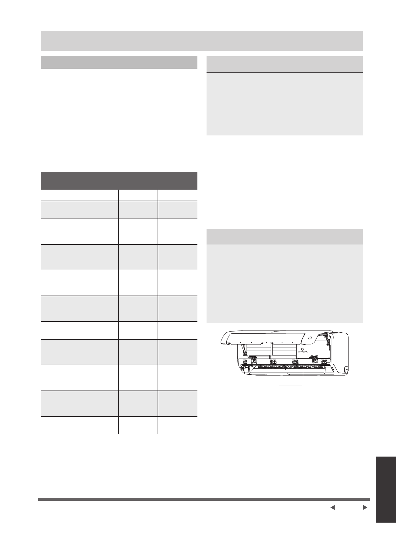
Page 37
Mise en service
Mise en service
Instructions de Mise en Service
Vous devez effectuer la mise en service pendant au
moins 30 minutes.
1. %UDQFKH]O¶DOLPHQWDWLRQjO¶XQLWp
2. $SSX\H]VXUOHERXWRQ212)) de la
WpOpFRPPDQGHSRXUO¶DOOXPHU
3. $SSX\H]VXUOHERXWRQMODE pour faire la tour
GHVIRQFWLRQVVXLYDQWHVXQHjODIRLV
Ɣ &22/6pOHFWLRQQH]ODWHPSpUDWXUHODSOXVEDVVH
SRVVLEOH
Ɣ +($76pOHFWLRQQH]ODWHPSpUDWXUHODSOXVpOHYpH
SRVVLEOH
4.
Laissez chaque fonction fonctionner pendant 5
PLQXWHVHWHIIHFWXH]OHVYpUL¿FDWLRQVVXLYDQWHV
/LVWHGHVFRQWU{OHVj
effectuer
5e866,7(e&+(&
Pas de fuite électrique
/¶XQLWpHVWFRUUHFWHPHQW
mis à la terre
7RXVOHVWHUPLQDX[
électriques sont
correctement couverts
Les unités intérieures
HWH[WpULHXUHV sont
solidement installées
Tous les points de
UDFFRUGHPHQWGHVWX\DX[
ne fuient pas
([WpULHXU
Intérieur (2)
/¶HDXV¶pFRXOH
correctement du tuyau de
YLGDQJH
Toute la tuyauterie est
correctement isolée
/¶XQLWpDVVXUH
correctement la fonction
&22/
/¶XQLWpDVVXUH
correctement la fonction
+($7
/HVYROHWVGHO¶XQLWp
intérieure tournent
correctement
/¶XQLWpLQWpULHXUHUpSRQG
à la télécommande
'28%/(&2175Ð/($8;5$&&25'(0(176'(
TUYAUX
3HQGDQWOHIRQFWLRQQHPHQWODSUHVVLRQGXFLUFXLW
UpIULJpUDQWDXJPHQWH&HODSHXWUpYpOHUGHVIXLWHV
TXLQ¶pWDLHQWSDVSUpVHQWHVORUVGHYRWUHFRQWU{OH
initiale.3UHQH]OHWHPSVSHQGDQWODPLVHHQVHUYLFH
GHYpUL¿HUTXHWRXVOHVSRLQWVGHUDFFRUGHPHQWGHV
FRQGXLWHVGHUpIULJpUDQWQHSUpVHQWHQWSDVGHIXLWHV
Veuillez reporter à la section 9pUL¿FDWLRQGHVIXLWHV
GHJD] pour les instructions.
5. Une fois que la mise en service est terminé avec
VXFFqVHWTXHYRXVDYH]FRQ¿UPpTXHWRXVOHV
SRLQWVGHFRQWU{OHGHODOLVWHGHVFRQWU{OHVj
HIIHFWXHUVRQWSDVVpVSURFpGH]FRPPHVXLW
D ¬O¶DLGHGHODWpOpFRPPDQGHUDPHQH]
O¶XQLWpjVDWHPSpUDWXUHQRUPDOHGH
fonctionnement.
E ¬O¶DLGHGHUXEDQLVRODQWHQYHORSSH]OHV
raccords des tuyaux de réfrigérant intérieur
TXHYRXVDYH]ODLVVpVGpFRXYHUWVORUVGH
l’installation de l’unité intérieure.
6,/$7(03e5$785($0%,$17((67
,1)e5,(85(¬&)
Vous ne pouvez pas utiliser la télécommande pour
DFWLYHUODIRQFWLRQ&22/ORUVTXHODWHPSpUDWXUH
DPELDQWHHVWLQIpULHXUHj&'DQVFHFDVYRXV
SRXYH]XWLOLVHUOHERXWRQ0$18$/&21752/ pour
WHVWHUODIRQFWLRQ&22/
/HERXWRQ0$18$/&21752/HVWVLWXpVXUOH
panneau latéral droit de l'appareil.
$SSX\H]GHX[IRLVVXUOHERXWRQSRXUVpOHFWLRQQHU
ODIRQFWLRQ&22/
3. Effectuez une la mise en service normalement.
Bouton de
commande
manuelle

Page 38
Emballage et
déballage de l’unité
Emballage et déballage de l’unité
Instructions pour l'emballage et le déballage de l'appareil :
Déballage :
Unité intérieure :
&RXSH]OHUXEDQGpWDQFKpLWpVXUOHFDUWRQDYHFXQFRXWHDXXQHFRXSHjJDXFKH
une coupe au milieu et une coupe à droite.
2. Utilisez l'étau pour retirer les clous de fermeture sur le dessus du carton.
2XYUH]OHFDUWRQ
4. Retirez la plaque de support centrale si elle est incluse.
6RUWH]OHPEDOODJHGHVDFFHVVRLUHVHWOH¿OGHFRQQH[LRQVLOHVWLQFOXV
6RUWH]ODPDFKLQHGXFDUWRQHWSRVH]ODjSODW
5HWLUH]ODPRXVVHGHPEDOODJHJDXFKHHWGURLWHRXODPRXVVHGHPEDOODJHVXSpULHXUH
HWLQIpULHXUHGpWDFKH]OHVDFGHPEDOODJH
Unité extérieure :
&RXSH]ODFHLQWXUHGHPEDOODJH
2. Sortez l'appareil du carton.
3. Retirez la mousse de l'unité.
5HWLUH]OHVDFGHPEDOODJHGHODSSDUHLO
Emballage :
Unité intérieure :
0HWWH]OXQLWpLQWpULHXUHGDQVOHVDFGHPEDOODJH
)L[H]OHVPRXVVHVGHPEDOODJHJDXFKHHWGURLWHRXOHVPRXVVHVGHPEDOODJH
supérieure et inférieure à l'unité.
3ODFH]ODSSDUHLOGDQVOHFDUWRQSXLVSODFH]OHPEDOODJHGHVDFFHVVRLUHV
)HUPH]OHFDUWRQHWVFHOOH]OHDYHFOHUXEDQDGKpVLI
8WLOLVH]ODFHLQWXUHGHPEDOODJHVLQpFHVVDLUH
Unité extérieure :
0HWWH]OXQLWpH[WpULHXUHGDQVOHVDFGHPEDOODJH
0HWWH]ODPRXVVHGXIRQGGDQVODERvWH
3ODFH]ODSSDUHLOGDQVOHFDUWRQSXLVPHWWH]ODPRXVVHGHPEDOODJHVXSpULHXUHVXU
l'appareil.
)HUPH]OHFDUWRQHWVFHOOH]OHDYHFOHUXEDQDGKpVLI
8WLOLVH]ODFHLQWXUHGHPEDOODJHVLQpFHVVDLUH
NOTE :9
HXLOOH]FRQVHUYHUWRXVOHVpOpPHQWVGHPEDOODJHVLYRXVHQDYH]EHVRLQj
l'avenir.


/DFRQFHSWLRQHWOHVVSpFLILFDWLRQVVRQWVXMHWWHVjFKDQJHPHQWVDQVSUpDYLV
SRXUO¶DPpOLRUDWLRQGXSURGXLW9HXLOOH]FRQVXOWHUO¶DJHQFHGHYHQWHRXOH
IDEULFDQWSRXUSOXVGHGpWDLOV7RXWHPLVHjMRXUGXPDQXHOVHUDWpOpFKDUJpH
VXUOHVLWHZHEGXVHUYLFHYHXLOOH]YpULILHUODGHUQLqUHYHUVLRQ
All specifications subject to change without notice.
©202
2 ECR International, Inc.
PN 615000577 [05/01/2022]
2201 Dwyer Avenue, Utica,a, NY 13501
Tel. 800 325-5479
www.ecrinternational.com