Page 1
PRODUCT INFORMATION:
INTENDED USE OF THE TOOL
WARNING
DO NOT DISCARD – GIVE TO USER
The manufacturer warrants this product to the original user
against defective material or workmanship for a period of 1
year from the date of purchase.
The manufacturer reserves the right to determine whether
the part or parts failed because of defective material,
workmanship or other causes. Failures caused by accident,
alteration, or misuse are not covered by this warranty.
The manufacturer, at its discretion, will repair or replace
product covered under this warranty free of charge. Repairs
or replacements of products covered under this warranty are
warranted for the remainder of the original warranty period.
The manufacturer or its authorized service representatives
must perform all warranty repairs. Any repair to the product
by unauthorized service representatives voids this warranty.
The rights under this warranty are limited to the original user
and may not be transferred to subsequent owners.
The warranty is in lieu of all other warranties, expressed or
implied, including warranties of merchantability and fitness
for a particular purpose. Some states do not allow the
exclusion or limitations of incidental or consequential
damages, so the above limitations may not apply to you.
1 YEAR LIMITED WARRANTY
1712467-14
MASTER FRONT WHEEL
DRIVE BEARING ADAPTER KIT
MBA25
When unpacking, check the parts diagram and part number
listing on page 7 to make sure all parts are included. If any
parts are missing or damaged, please call your distributor.
BEFORE USE
Study, understand and follow all instructions provided with
this product. Read these instructions carefully before
installing, operating, servicing or repairing this tool. Keep
these instructions in a safe accessible place.
The Master Front Wheel Drive Bearing Adapter Kit is for the
removal and insulation of wheel bearing using the drive bolt
and adapter in the kit only. Do not modify or replace any
pieces of this kit with foreign parts. Do not use these tools
outside of the designed intent. Never modify the tools for any
other purpose or use.
Made in China
to Matco specifications
Caution: To help prevent personal injury
• Normal use of this product is likely to expose the user to dust
and/or microscopic particles containing chemicals known to the
State of California to cause cancer, birth defects or other
reproductive harm. Always wear appropriate safety equipment and
clothing when using this product. Study, understand and follow all
instructions provided with this product. Failure to read and follow
all warnings and operating instructions may result in damages
and serious injury or death.
• Always wear ANSI approved goggles when using this product.
(Users and Bystanders).
• Never use this tool for any application other than for
which it was designed.
• Only use accessories designed for this tool.
• Never alter or modify this tool in any way.
• Improper operation and/or maintenance of the tool, modification of
the tool, or use of the tool with accessories not designed for it
could result in serious injury or death.
• Always select the correct accessories of the correct size and
design for the job that you are attempting to perform.
• Always work in a clean, safe, well-lit, organized and adequately
equipped area.
• Do not begin repairs without assurance that vehicle is in secure
position, and will not move during repair.
WARNING
Industry leading durability. 1.25" Hex, 7/8" thread U.S. Grade
8 drive bolt and hardened washers provide two times the tool
life of comparable sets and allow for impact use.
Quicker and easier. Perform wheel bearing service while
strut assembly, hub and knuckle are still attached to the
vehicle, avoiding the need for an alignment after.
Wide application range. 25 piece kit includes press bushings
from 2.18" to 3.5" and sleeves from 3” to 4” to fit most FWD
and AWD applications.
Specifications:
Finish:
Bushing Range:
(Outside Diameter)
Sleeve Sizes:
Sleeve Plate Sizes:
Drive Bolt:
Bolt Rating:
Nut Size:
Washer:
Black Oxide, Zinc Plating
2.18", 2.5", 2.62", 2.78", 2.82", 2.88",
2.9", 2.96", 3.05", 3.21", 3.28", 3.48"
3" O.D. × 2.5" Long
3.25" O.D. × 2.53" Long
3.63" O.D. × 2.53" Long
4" O.D. × 2.53" Long
3.25" O.D. × 2.72" Step
4" O.D. × 3.2" Step
7.5" x 7/8" x 1.25" (32mm) Hex
SAE Grade 8
3" Long × 1.25" (32mm) Hex
Hardened, 1.5" OD
Page 2
1712467-14
MASTER FRONT WHEEL
DRIVE BEARING ADAPTER KIT
MBA25
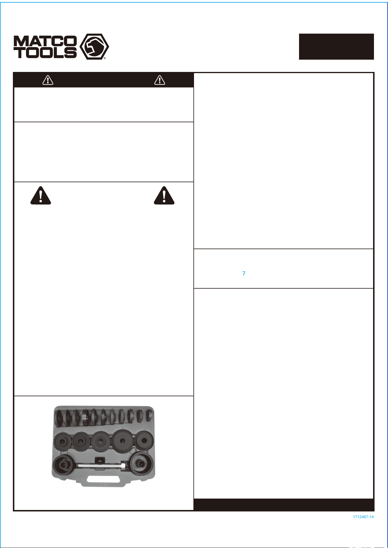
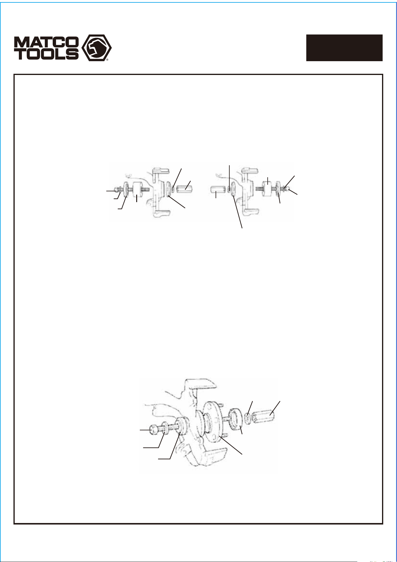
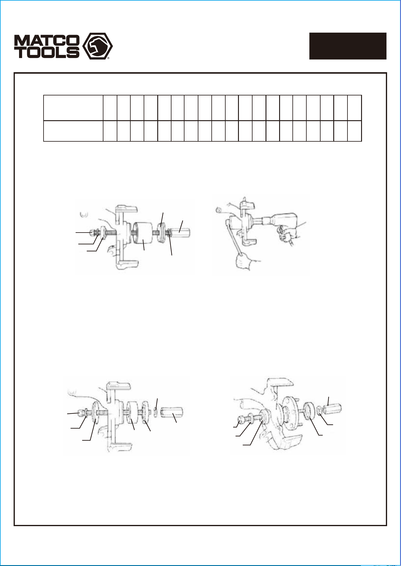
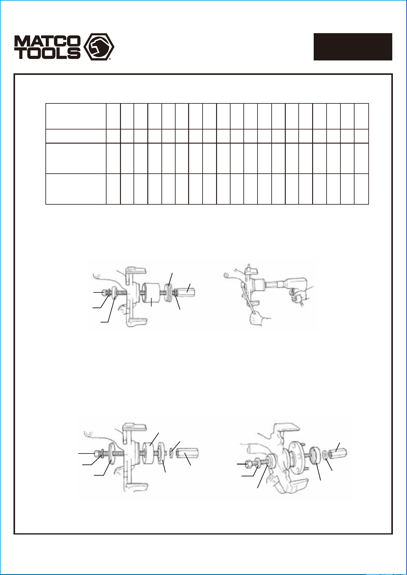
CHRYSLER/PLYMOUTH/DODGE
FIGURE 3
MBA25-18
MBA25-19
MBA25-07
MBA25-19
MBA25-17
MBA25-13
(flat side toward bearing)
MBA25-18
MBA25-05
MBA25-19
MBA25-19
MBA25-17
MBA25-21
(not used for
Colt Neon)
New Bearing
MBA25-A
or
MBA25-B
FIGURE 2
MBA25-18
MBA25-19
MBA25-16
or
MBA25-20
MBA25-19
MBA25-17
MBA25-A
or
MBA25-B
MBA25-13
FIGURE 1
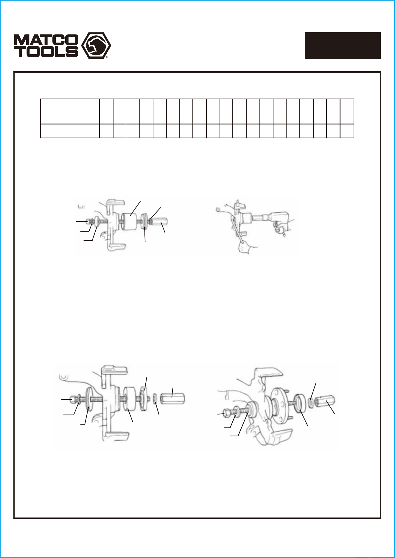
1. Determine if the vehicle has a trapped rotor
or a floating rotor.
2. Assemble the tool components as shown in
Figure 1, and press out the worn bearing.
3. Lightly lubricate the new bearing, and
position it for installation with the tool
components assembled as shown in Figure
2. Press the bearing into the spindle
assembly until it bottoms out.
4. Fasten the bearing retainer in place using
the bearing retainer bolts. (On Neon
vehicles, install the snap ring in the knuckle.)
5. Assemble tool components as shown in
Figure 3. Lightly oil the hub assembly, and
install the hub.
Important: The bearing installer must be
assembled with the flat side toward the
bearing and the small diameter pilot on
the side away from the bearing.
6. Assemble the remaining vehicle components
that were removed for bearing replacement:
• Lower ball joint to steering knuckle assembly
• Brake rotor
• Disc brake caliper
• Outer tie rod nut and tie rod
• Axle nut
• Front tires
R = Remove
I = Install
Chrysler
1982-88 All
1989-90 LeBaron
1989-90 Town & Country
Plymouth
1980-83 All
1983 Voyager
1984-90 Acclaim, Caravelle,
Reliant, Sundance
1984-90 Horizon Turismo
1984-90 Voyager
Dodge
1980-83 All
1982-84 Rampage
1984-87 Charger
1984-89 Dynasty, Shelby
Charger, 600
1984-89 Omni GLH
1984-90 Aries. Lancer.
Shadow
1984-90 Caravan
1984-90 Daytona
1984-90 Omni
1989-90 Spirit
1993-94 Colt
1995-00 Neon
2001-04 Neon
2001-04 PT Cruiser
R
R
RI
RI RI
RII I I
III
R RI RI II
RIRIR II
I
MBA25-16
MBA25-15
MBA25-B
MBA25-11
MBA25-09
MBA25-06
MBA25-06
MBA25-08
MBA25-01
MBA25-04
MBA25-03
MBA25-02
MBA25-20
MBA25-21
MBA25-A
MBA25-05
MBA25-10
MBA25-13
MBA25-07
Page 3
1712467-14
MASTER FRONT WHEEL
DRIVE BEARING ADAPTER KIT
MBA25
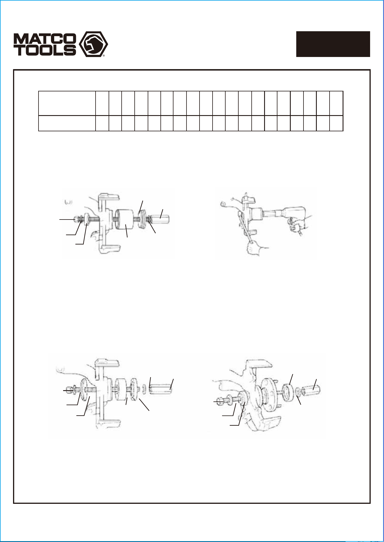
FIGURE 1
MBA25-18
MBA25-19
Front Wheel Knuckle
MBA25-A
or
MBA25-B
MBA25-20
or
MBA25-21
or
MBA25-16
MBA25-19
MBA25-13
MBA25-17
1986-95 Taurus/Sable
1995-98 Windstar
1983-94 Tempo/Topaz
1983-90 Escort/Lynx
1993-97 Probe
2000-04 Focus
MBA25-17
MBA25-18
MBA25-19
MBA25-19
MBA25-13
or
MBA25-06
MBA25-20
or
MBA25-16
MBA25-A
or
MBA25-B
FIGURE 2
1995-2001 Contour/Mystique
1991-99 Escort/Tracer
1993-99 Villager
1986-95 Taurus/Sable
1995-98 Windstar
1983-94 Tempo/Topaz
1983-90 Escort/Lynx
1993-97 Probe
2000-04 Focus
FIGURE 3
FIGURE 4
1995-2001 Contour/Mystique
1991-99 Escort/Tracer
1993-99 Villager
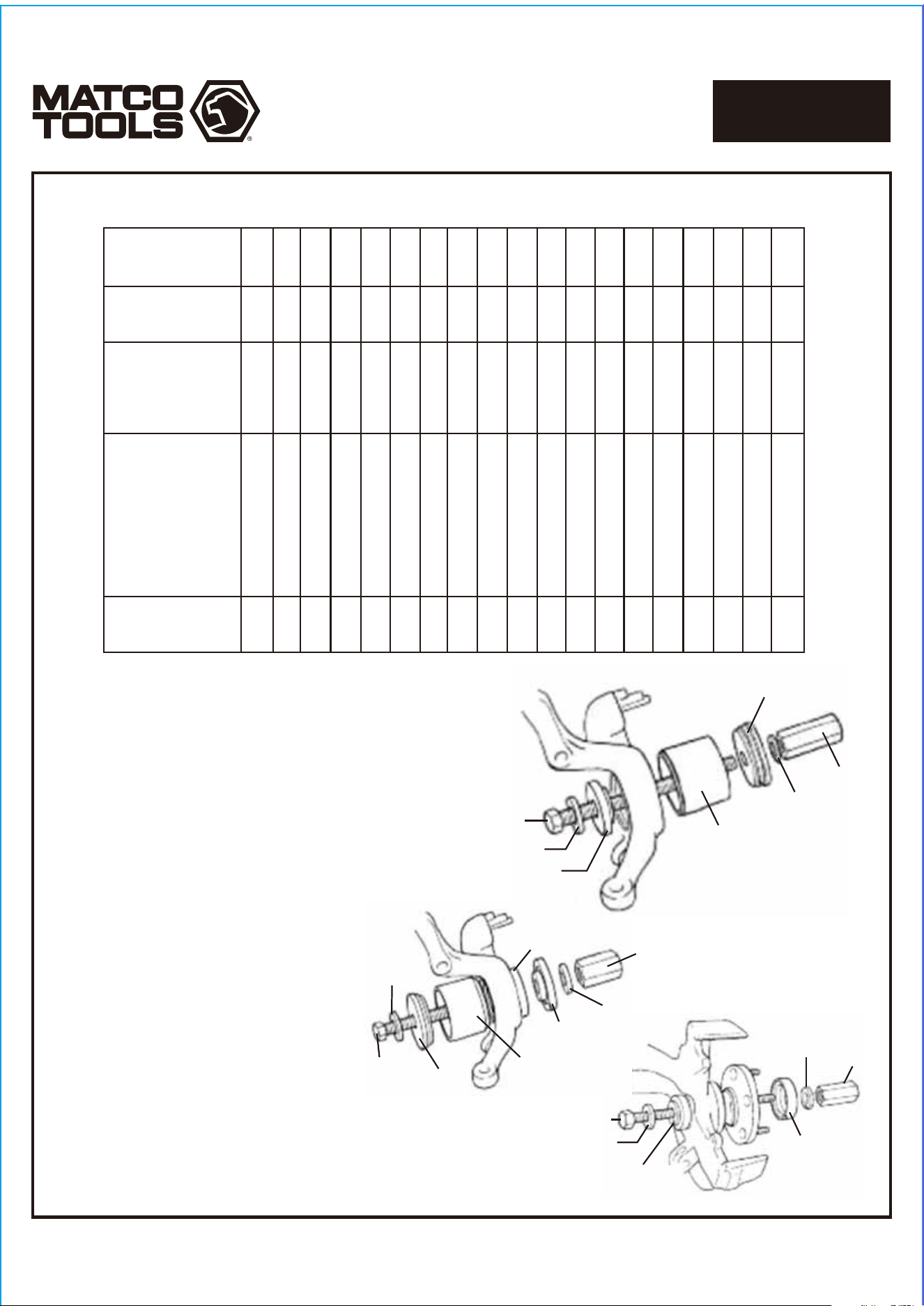
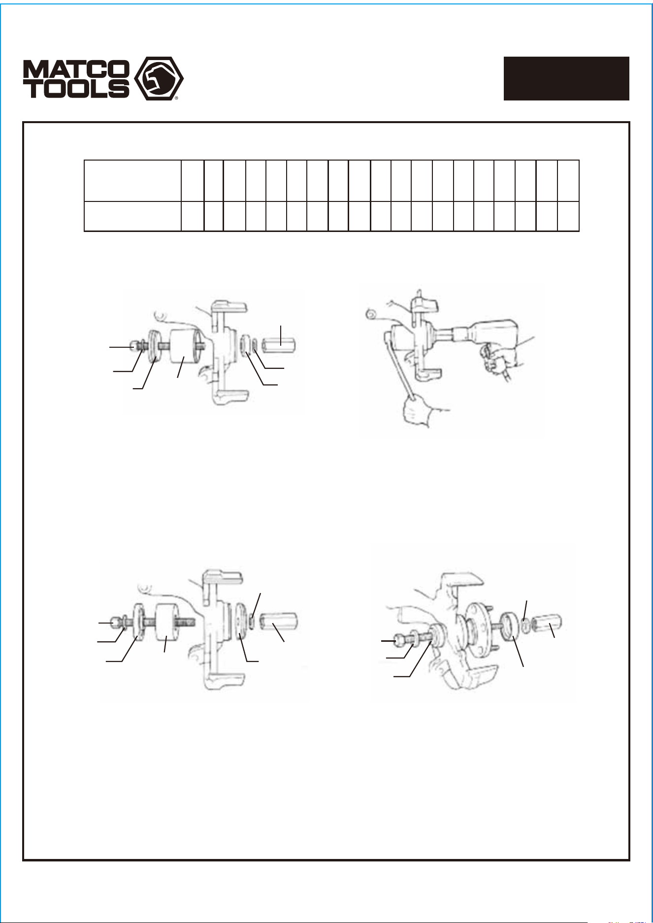
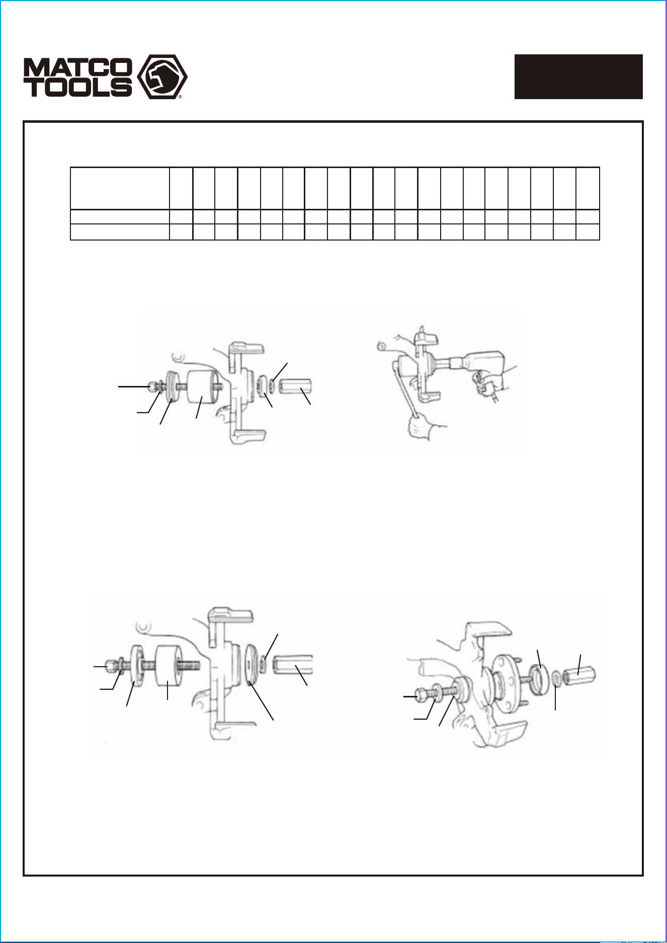
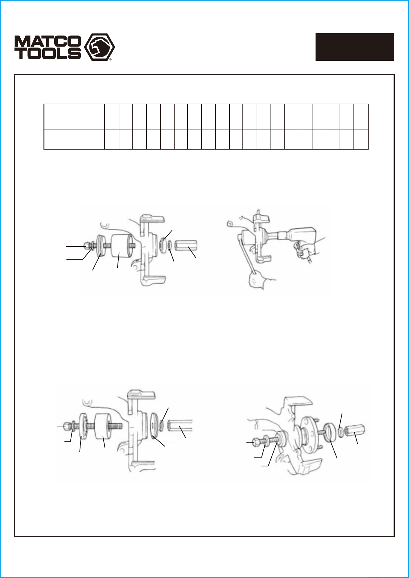
1. Determine if the vehicle has a trapped rotor or a floating rotor.
2. Assemble the tool components as shown.
Important: The internal chamfer on the end of the tube (No. MBA25-20 or MBA25-21) faces the wheel knuckle.
The chamfer aligns the tube with the wheel knuckle so it doesn't slip off the surface and cock.
The 1986-95 Taurus/Sable application uses the larger tube (No.MBA25-20) with the 2-step adapter (No.MBA25-A).
See Figure 1.
The 1983-94 Tempo/Topaz and 1983-90 Escort/Lynx application uses the smaller tube (No.MBA25-21) with the 2-step
adapter. See Figure 1.
The 1995-2001 Contour/Mystique application uses bearing installer No.MBA25-13. See Figure 2.
The 1991-99 Escort/Tracer application uses bearing installer No.MBA25-06. See Figure 2.
The 1993-99 Villager application uses bearing installer No.MBA25-16 and step adapter No.MBA25-B. See Figure 2.
3. Use a wrench to hold the forcing screw (Figure 3) or forcing screw nut (Figure 4), and press out the worn bearing.
FORD/MERCURY
R = Remove
I = Install
R R
R
R
R
R
R R
R
R
RR
RI
RI
RI
RI
RI
RI
RI
RI
RI I
I
I
I I
I
I
I
I
I
I
I
I
I
I
I
1983-90 Escort/Lynx.
EXP /Ln7
1983-94 Tempo/Topaz
19886-95 Taurus/Sable
1995-98 Windstar
1993-97 Probe
1991-99 Escort/Tracer
1993-99 Villager
1995-01 Contour/Mystique
2000-04 Focus
1994-97 Aspire
MBA25-16
MBA25-15
MBA25-B
MBA25-11
MBA25-09
MBA25-06
MBA25-06
MBA25-08
MBA25-01
MBA25-04
MBA25-03
MBA25-02
MBA25-20
MBA25-21
MBA25-A
MBA25-05
MBA25-10
MBA25-13
MBA25-07
Page 4
1712467-14
MASTER FRONT WHEEL
DRIVE BEARING ADAPTER KIT
MBA25
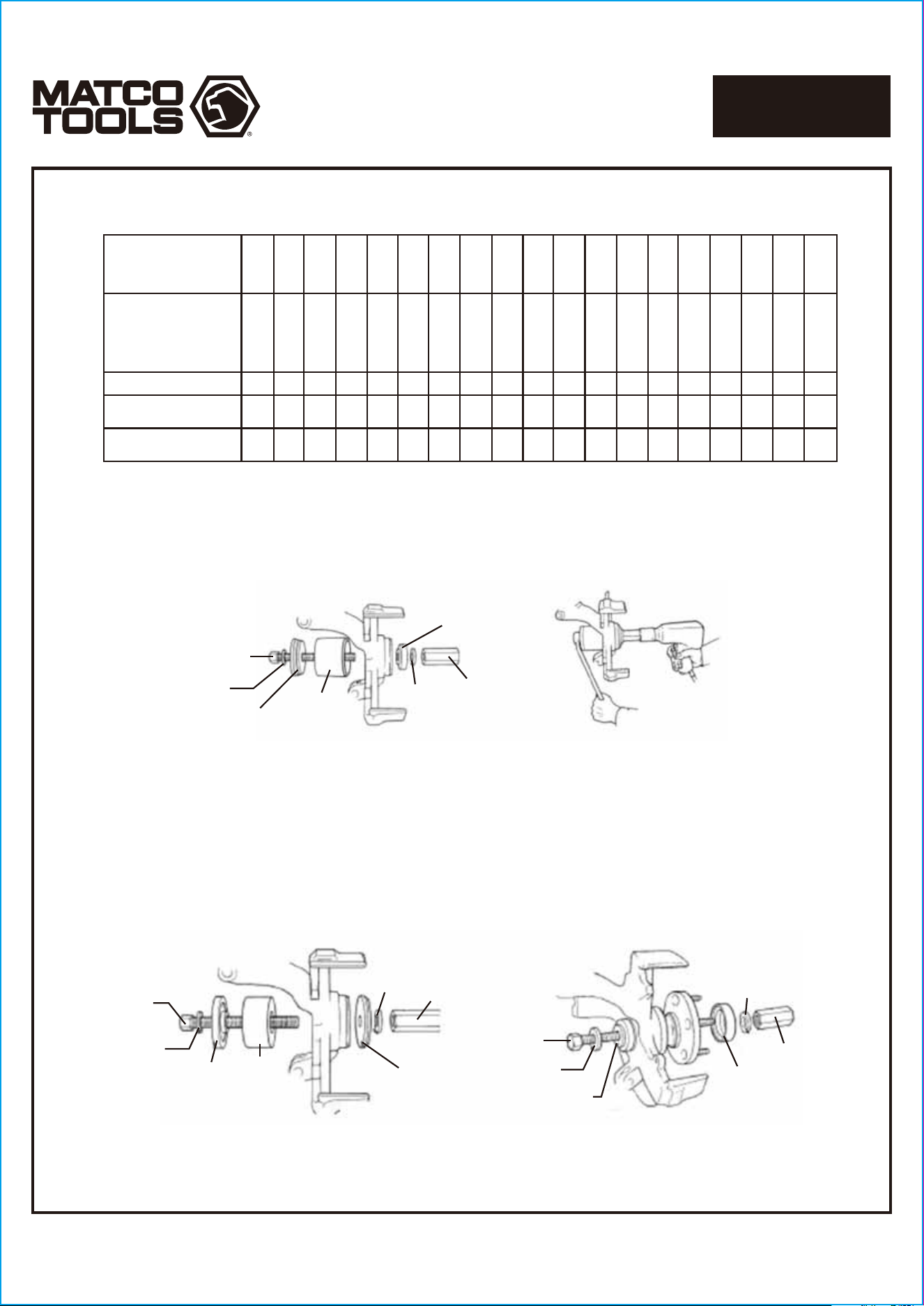
1986-95 Taurus/Sable
1995-98 Windstar
1983-94 Tempo/Topaz
1983-90 Escort/Lynx
1993-97 Probe
2000-04 Focus
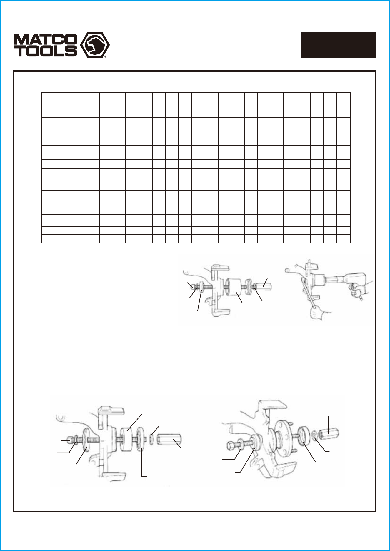
FIGURE 5
FIGURE 6
1995-2001 Contour/Mystique
1991-99 Escort/Tracer
1993-99 Villager
MBA25-18
MBA25-19
MBA25-17
MBA25-17
MBA25-19
MBA25-19
MBA25-18
MBA25-19
MBA25-05
or
MBA25-10
or
MBA25-04
MBA25-06
or
MBA25-08
or
MBA25-04
MBA25-A
or
MBA25-B
(flat side toward housing)
MBA25-A
(flat side toward housing)
New
Bearing
New
Bearing
Front
FIGURE 7
MBA25-18
MBA25-19
MBA25-13
(flat side toward bearing)
Wheel Hub
MBA25-07
MBA25-19
MBA25-17
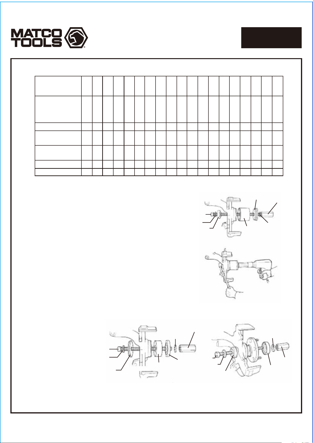
4. Lightly lubricate the new bearing, and position it for installation with the tool components assembled as shown.
The 1986-95 Taurus/Sable application uses the larger bearing installer (No.MBA25-05).see Figure 5.
The 1983-94 Tempo/Topaz and 1983-90 Escort/Lynx application uses the smaller bearing installer
(No.MBA25-10). See Figure 5.
The 1995-2001 contour/Mystique application uses bearing installer No.MBA25-08 .See Fig.6.
Important: To prevent damage to the seal lip, remove the seal before installing the bearing.
The 1993-99 Villager application uses adapter No.MBA25-04. See Fig.6.
5. Press the bearing into the spindle assembly until it bottoms, Install the snap ring that was removed from the knuckle.
6. Assemble the tool components as shown in Figure 7. and install the hub.
Important: The bearing installer must be assembled with the flat side toward the bearing and the small diameter pilot
on the side away from the bearing.
On the 1991-99 Escort/Tracer application, install the seal after the wheel hub has been assembled.
7. Assemble the remaining vehicle components that were removed for bearing replacement:
• Lower ball joint to steering knuckle assembly
• Brake rotor
• Disc brake caliper
• Outer tie rod nut and tie rod
• Axle nut
• Front tires
Page 5
1712467-14
MASTER FRONT WHEEL
DRIVE BEARING ADAPTER KIT
MBA25
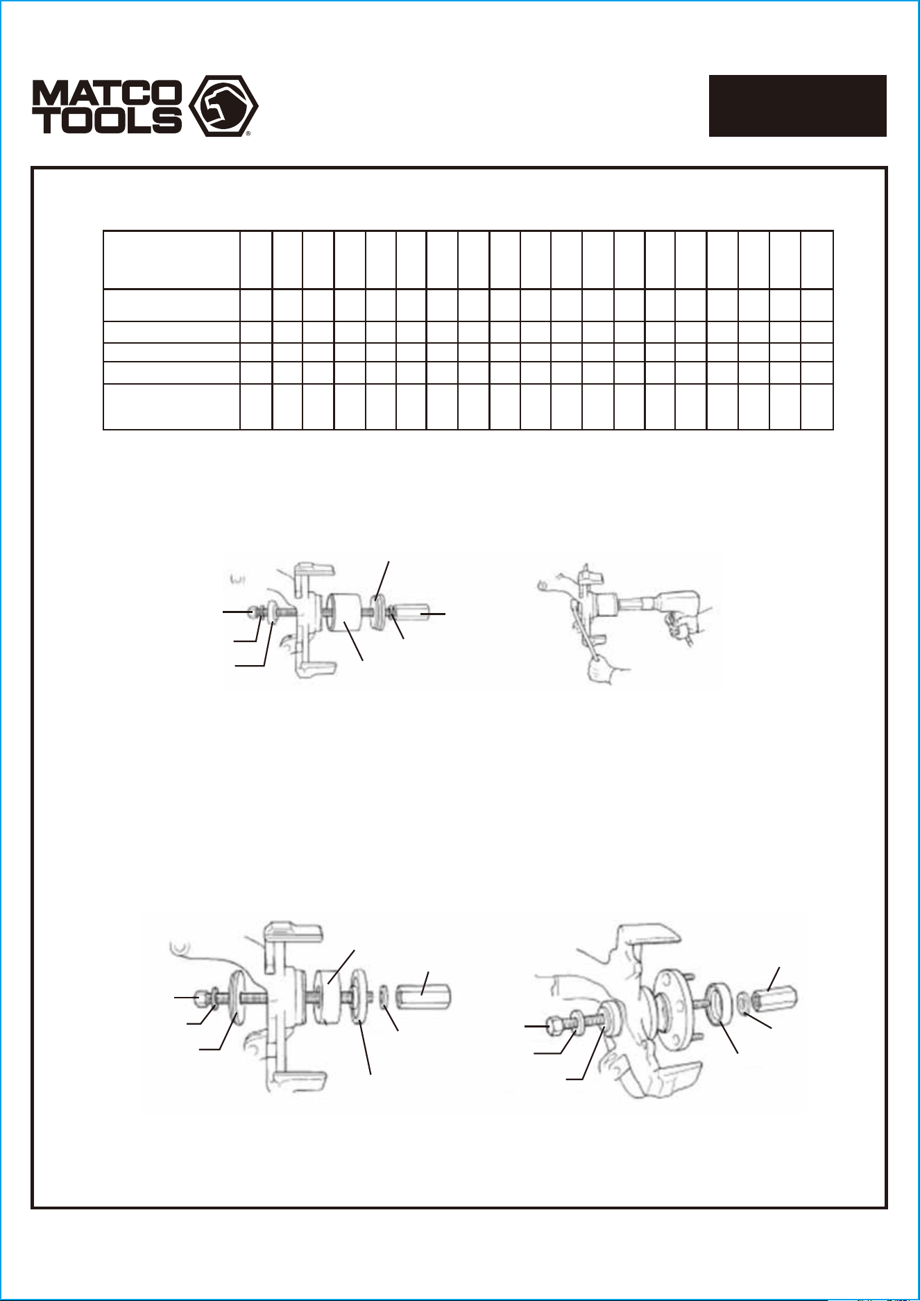
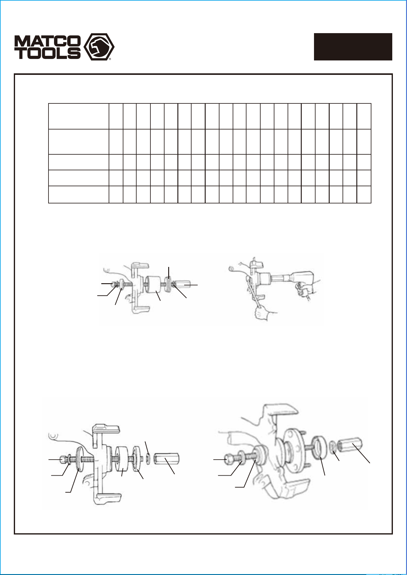
Figure 2
Figure 1
MBA25-18
MBA25-19
MBA25-19
MBA25-13
MBA25-20
MBA25-17
MBA25-A
MBA25-18
MBA25-19
Figure 3 Figure 4
MBA25-A
(flat side
toward housing)
MBA25-17
MBA25-10
MBA25-18
MBA25-19
MBA25-07
MBA25-19
MBA25-17
MBA25-13
(flat side toward bearing)
New
Bearing
Front
MBA25-19
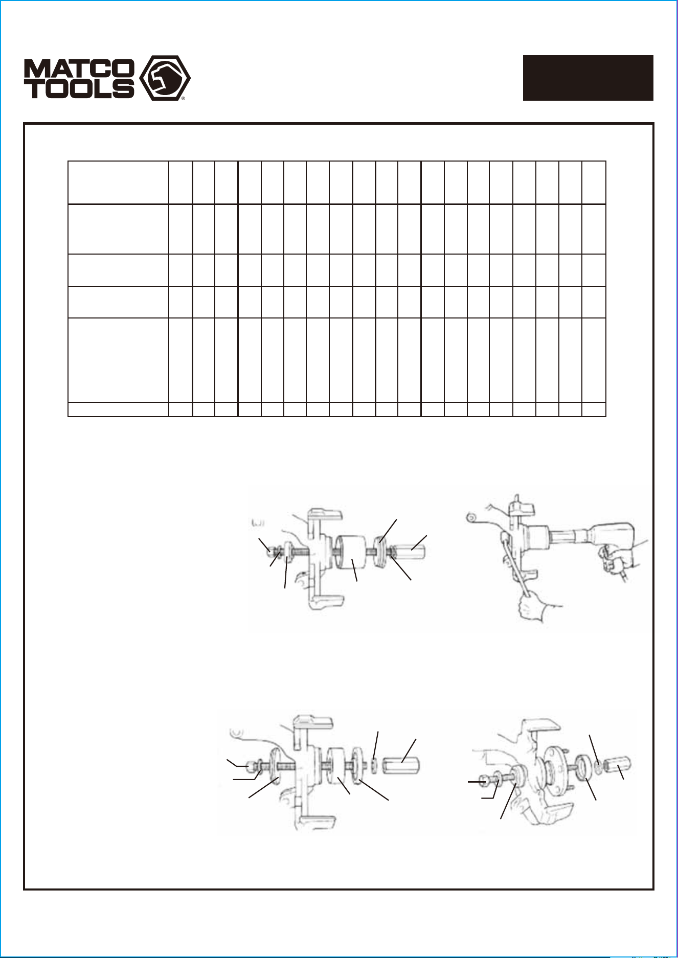
SATURN
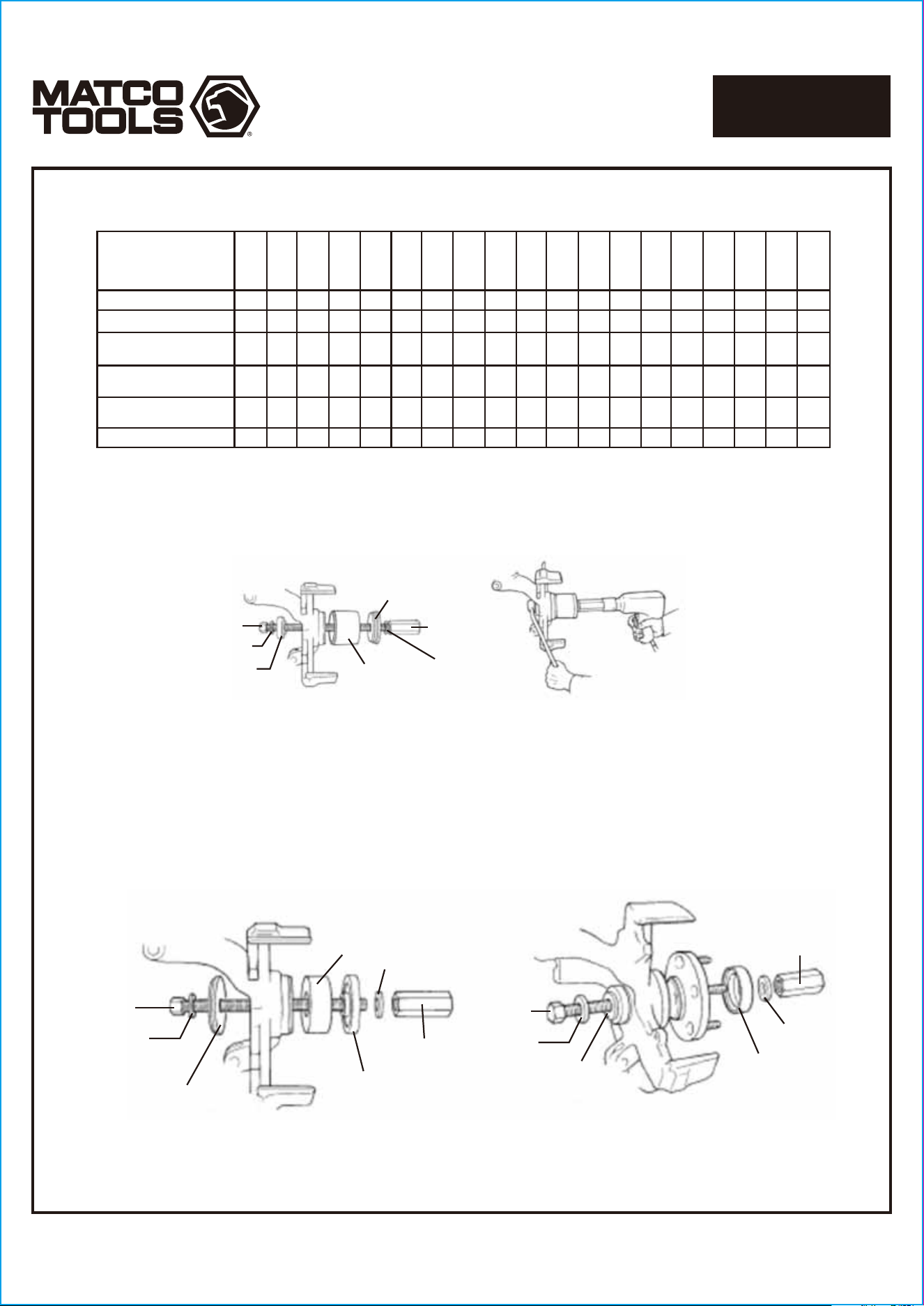
1. Determine if the vehicle has a trapped rotor or a floating rotor.
2. Assemble the tool components as shown in Figure 1. Hold the forcing screw with a wrench, and press the worn bearing out as
shown in Figure 2.
3. Lightly lubricate the new bearing, and position if for installation with the tool components assembled as shown in Figure 3.
Important: Assemble the adapter with the flat side toward the housing, and the small diameter pilot on the side away
from the housing.
4. Press the bearing into the spindle assembly until it bottoms, install the snap ring.
5. Assemble the tool components as shown in Figure 4, and install the hub.
Important: The bearing installer must be assembled with the flat side toward the bearing and the small diameter pilot
on the side away from the bearing.
R = Remove
I = Install
R RIRI II
1991-99 SC,SC1,SC2,SL,
SL1,SL2,SW1,SW2
MBA25-16
MBA25-15
MBA25-B
MBA25-11
MBA25-09
MBA25-06
MBA25-06
MBA25-08
MBA25-01
MBA25-04
MBA25-03
MBA25-02
MBA25-20
MBA25-21
MBA25-A
MBA25-05
MBA25-10
MBA25-13
MBA25-07
Page 6
1712467-14
MASTER FRONT WHEEL
DRIVE BEARING ADAPTER KIT
MBA25
Figure 2
Figure 1
MBA25-18
MBA25-B
or
MBA25-A
MBA25-19
MBA25-19
MBA25-17
MBA25-11
or
MBA25-13
MBA25-20
or
MBA25-16
or
MBA25-15
Figure 3 Figure 4
MBA25-18
MBA25-18
MBA25-19
MBA25-07
MBA25-17
MBA25-19
MBA25-13
or
MBA25-11
(flat side toward bearing)
MBA25-17
MBA25-19
MBA25-19
MBA25-06
or
MBA25-01
or
MBA25-04
or
MBA25-03
or
MBA25-02
MBA25-B
(flat side toward housing)
New
Bearing
ACURA
R = Remove
I = Install
R
R
R
R
R
R R
RI RI
RI
RI
RI
RI
RI
RI
RI
RI
RI
RI
I
I
I
I
I
I
I
I
I
I
I
I
I
1986-89 Integra
1986 Legend
1987 Legend(sedan)
1990-93 Integra
1991-03 NSX
1995-99 2.5TL 3.0CL
1996-99 2.2CL.2.3CL
1987 Legend(coupe)
1988-90 Legend
1992-94 Vigor
1991-99 Legend.3.2TC
1991-03 3.5RL
2002-03 RSX
1999-03 3.2
1994-01 Integra
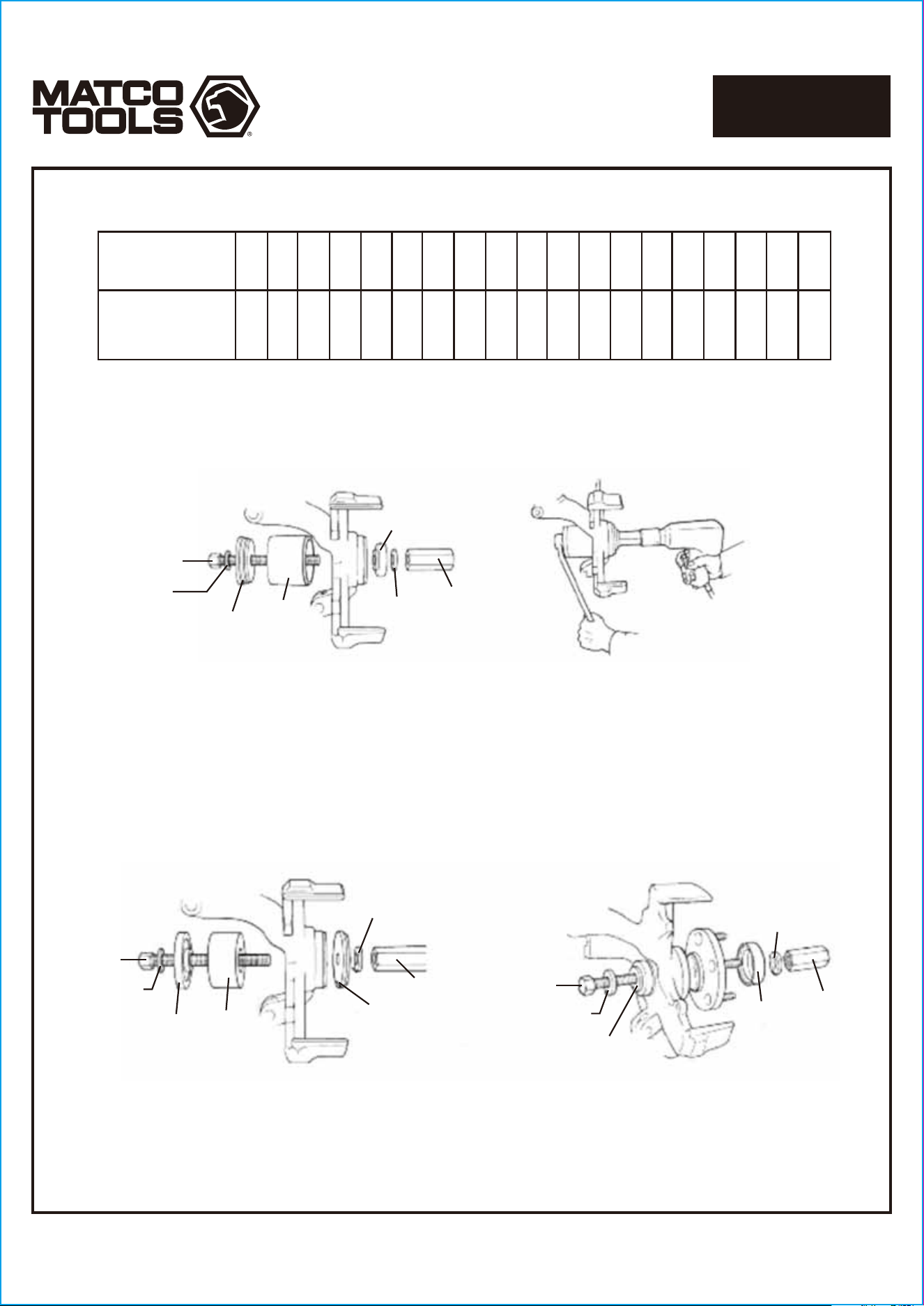
Bearing Removal and Installation
1. Determine if the vehicle has a trapped rotor or a floating rotor.
2. Assemble tool components as shown in Figure 1.
3. Hold the forcing screw with a wrench, and press out the worn bearing
as shown in Figure 2.
4. Lightly lubricate the new bearing, and position it for installation with
the tool components assembled as shown in Figure 3.
Important: Assemble the adapter with the flat side toward the
housing, and the small diameter pilot on the side away from the
housing.
5. Press the bearing into the spindle assembly until it bottoms. Install the
snap ring.
6. Assemble tool components as shown in Figure 4, and install the hub.
Important: Assemble the bearing Installer with the flat side
toward the bearing, and the small diameter pilot on the side
away from the bearing.
7. Assemble the remaining vehicle components that were removed for
bearing replacement:
• Lower ball joint to steering knuckle assembly
• Brake rotor
• Disc brake caliper
• Outer tie rod nut and tie rod
• Axle nut
• Front tires
MBA25-16
MBA25-15
MBA25-B
MBA25-11
MBA25-09
MBA25-06
MBA25-06
MBA25-08
MBA25-01
MBA25-04
MBA25-03
MBA25-02
MBA25-20
MBA25-21
MBA25-B
MBA25-05
MBA25-10
MBA25-13
MBA25-07
MBA25-18
Figure 1
Figure 2
MBA25-19
MBA25-19
MBA25-17
MBA25-20
or
MBA25-21
or
MBA25-16
or
MBA25-15
MBA25-B
or
MBA25-A
MBA25-13
Figure 3 Figure 4
MBA25-18
MBA25-18
MBA25-19
MBA25-13
(flat side toward bearing)
MBA25-19
MBA25-19
MBA25-10
or
MBA25-08
or
MBA25-03
or
MBA25-02
MBA25-17
MBA25-B
(flat side toward housing)
New
Bearing
MBA25-07
MBA25-17
MBA25-19
AUDI
R = Remove
I = Install
R
R
R
R
R R
R
R
RI
RI
RI
RI
RI
RI
RI
I
I
I I
I
I
I
I
I
I
I
II
I
1980-86 Quattro,5000,
5000 Quattro
1986-88 5000,5000 Quattro
1989-90 100,200(ATX)
1991 100,200(ATX 3 speed)
Bearing Removal and Installation
1.Determine if the vehicle has a trapped rotor or a floating rotor.
2. Assemble tool components as shown in Figure 1.
3. Hold the forcing screw with a wrench, and press
out the worn bearing as shown in Figure 2.
4. Lightly lubricate the new bearing, and
position it for installation with the tool
components assembled as
shown in Figure 3.
Important: Assemble the adapter
with the flat side toward the housing,
and the small diameter pilot on the
side away from the housing.
5. Press the bearing into the spindle assembly
until it bottoms. Install the snap ring.
6. Assemble tool components as shown
in Figure 4 to install the hub.
Important: Assemble the bearing installer
with the flat side toward the bearing,
and the small diameter pilot on the
side away from the bearing.
7. Assemble the remaining vehicle
components that were removed
for bearing replacement:
• Lower ball joint to steering
knuckle assembly
• Brake rotor
• Disc brake caliper
• Outer tie rod nut and tie rod
• Axle nut
• Front tires
1980-87 Coupe,4000
4000 Coupe
1988 80 series
1988-94 Quattro (coupe).
80 series,80 Quattro,
90 series,90 Quattro
1989-93 100,200(MTX)
V8 Quattro,100 Quattro,
200 Quattro
1991 100,200(ATX4 speed)
1992-99 S4,V8 Quattro,
100 Quattro
1996-03 A4
1992-03A6,S6
1992-04,A8,Quattro
1996-02 A4 Exc Quattro
MBA25-16
MBA25-15
MBA25-B
MBA25-11
MBA25-09
MBA25-06
MBA25-06
MBA25-08
MBA25-01
MBA25-04
MBA25-03
MBA25-02
MBA25-20
MBA25-21
MBA25-B
MBA25-05
MBA25-10
MBA25-13
MBA25-07
Page 7
1712467-14
MASTER FRONT WHEEL
DRIVE BEARING ADAPTER KIT
MBA25
Page 8
1712467-14
MASTER FRONT WHEEL
DRIVE BEARING ADAPTER KIT
MBA25
MBA25-18
MBA25-16
MBA25-19
Figure 1 Figure 2
MBA25-B
MBA25-17
MBA25-19
MBA25-13
Figure 3 Figure 4
MBA25-18
MBA25-18
MBA25-17
MBA25-19
MBA25-07
MBA25-19
MBA25-13
(flat side toward bearing)
MBA25-19
MBA25-B
(flat side toward housing)
New
Bearing
MBA25-05
MBA25-19
MBA25-17
R = Remove
I = Install
R RIRI II
1993-96 Summit
1992-96 Summit Wagon
1990-94 Talon
EAGLE
Bearing Removal and Installation
1. Determine if the vehicle has a trapped rotor or a floating rotor.
2. Assemble tool components as shown in Figure 1.
3. Hold the forcing screw with a wrench, and press out the worn bearing as shown in Figure 2.
4. Lightly lubricate the new bearing, and position it for installation with the tool components assembled as shown in Figure 3.
Important: Assemble the adapter with the flat side toward the housing, and the small diameter pilot on the side away
from the housing.
5. Press the bearing into the spindle assembly until it bottoms. Install the snap ring.
6. Assemble tool components as shown in Figure 4 to install the hub.
Important: Assemble the bearing installer with the flat side toward the bearing, and the small diameter pilot on the
side away from the bearing.
MBA25-16
MBA25-15
MBA25-B
MBA25-11
MBA25-09
MBA25-06
MBA25-06
MBA25-08
MBA25-01
MBA25-04
MBA25-03
MBA25-02
MBA25-20
MBA25-21
MBA25-A
MBA25-05
MBA25-10
MBA25-13
MBA25-07
Page 9
1712467-14
MASTER FRONT WHEEL
DRIVE BEARING ADAPTER KIT
MBA25
Figure 2Figure 1
MBA25-18
MBA25-A
MBA25-17
MBA25-19
MBA25-13
MBA25-21
MBA25-19
Figure 3 Figure 4
MBA25-18
MBA25-19
MBA25-19
MBA25-17
MBA25-A
(flat side toward housing)
MBA25-18
MBA25-19
MBA25-13
(flat side toward bearing)
New
Bearing
MBA25-13
MBA25-19
MBA25-17
MBA25-07
R = Remove
I = Install
R RIRI I
1989-97 Prizm
1995-98 Metro
GEO
Bearing Removal and Installation
1. Determine if the vehicle has a trapped rotor or a floating rotor.
2. Assemble tool components as shown in Figure 1.
3. Hold the forcing screw with a wrench, and press out the worn bearing as shown in Figure 2.
4. Lightly lubricate the new bearing, and position it for installation with the tool components assembled as shown in Figure 3.
Important: Assemble the adapter with the flat side toward the housing, and the small diameter pilot on the side away
from the housing.
5. Press the bearing into the spindle assembly until it bottoms. Install the snap ring.
6. Assemble tool components as shown in Figure 4 to install the hub.
Important: Assemble the bearing installer with the flat side toward the bearing, and the small diameter pilot on the
side away from the bearing.
MBA25-16
MBA25-15
MBA25-B
MBA25-11
MBA25-09
MBA25-06
MBA25-06
MBA25-08
MBA25-01
MBA25-04
MBA25-03
MBA25-02
MBA25-20
MBA25-21
MBA25-B
MBA25-05
MBA25-10
MBA25-13
MBA25-07
MBA25-18
MBA25-19
MBA25-19
MBA25-11
or
MBA25-13
MBA25-B
or
MBA25-A
MBA25-17
MBA25-20
or
MBA25-16
or
MBA25-15
Figure 1
Figure 2
Figure 3 Figure 4
MBA25-18
MBA25-18
MBA25-19
MBA25-19
MBA25-13
or
MBA25-11
(flat side toward bearing)
MBA25-A
or
MBA25-B
(flat side toward housing)
New Bearing
MBA25-19
MBA25-17
MBA25-17
MBA25-19
MBA25-07
MBA25-11
or
MBA25-06
or
MBA25-01
or
MBA25-04
or
MBA25-03
R = Remove
I = Install
R
R
R
R
R
R
R
R
R
R
RI
RI
RI
RI
RI
RI
RI
RI
RI
RI
RI
RIRI
RI
RI
RI
RI
RI
RI
RI
I
I
I
I
I
I
I
I
I
I
I
I
I
I
I
I
I
I
I
I
I
1980-85 Accord
1980-87 Prelude
1984-91 Civic.CRX.
Civic Wagon 4WD
HONDA
Bearing Removal and Installation
1. Determine if the vehicle has a trapped rotor or a
floating rotor.
Note: Some Honda vehicles use a bolt-in bearing
instead of a pressed-in bearing. Refer to Hub Tamer
Instructions-Trapped Rotors to service these
bearings.
2. Assemble tool components as shown in Figure 1.
3. Hold the forcing screw with a wrench, and press out
the worn bearing as shown in Figure 2.
4. Lightly lubricate the new bearing, and position it for installation with the tool components assembled as shown in Figure 3.
Important: Assemble the adapter with the flat side toward the housing, and the small diameter pilot on the side away
from the housing.
5. Press the bearing into the spindle assembly until it bottoms. Install the snap ring.
6. Assemble tool components as shown in Figure 4, and install the hub.
Important: Assemble the bearing Installer with the flat side toward the bearing, and the small diameter pilot on the
side away from the bearing.
1986-89 Accord
1992-99 Civic.del Sol
1988-96 Prelude
1996-00 Civic EXC.EX.Si
1992-96 Prelude
2003 Accord
2001-03 Civic
1996-00 Civic EX.Si
1994-97 del Sol
1992-95 Civic w/ABS
2000-03 S2000
1997-01 Prelude
1999-03 Odyssey
1998-02 Accord
MBA25-16
MBA25-15
MBA25-B
MBA25-11
MBA25-09
MBA25-06
MBA25-06
MBA25-08
MBA25-01
MBA25-04
MBA25-03
MBA25-02
MBA25-20
MBA25-21
MBA25-A
MBA25-05
MBA25-10
MBA25-13
MBA25-07
Page 10
1712467-14
MASTER FRONT WHEEL
DRIVE BEARING ADAPTER KIT
MBA25
Page 11
1712467-14
MASTER FRONT WHEEL
DRIVE BEARING ADAPTER KIT
MBA25
MBA25-19
MBA25-13
MBA25-18
Figure 1 Figure 2
MBA25-20
or
MBA25-16
or
MBA25-15
MBA25-A
or
MBA25-B
MBA25-19
MBA25-17
Figure 4
Figure 3
MBA25-18
MBA25-18
MBA25-07
MBA25-19
MBA25-17
MBA25-19
MBA25-13
(flat side toward bearing)
MBA25-17
New
Bearing
MBA25-19
MBA25-10
or
MBA25-09
or
MBA25-04
or
MBA25-02
MBA25-19
MBA25-A
or
MBA25-B
(flat side toward housing)
Bearing Removal and Installation
1. Determine if the vehicle has a trapped rotor or a floating rotor.
2. Assemble tool components as shown in Figure 1.
3. Hold the forcing screw with a wrench, and press out the worn bearing as shown in Figure 2.
4. Lightly lubricate the new bearing, and position it for installation with the tool components assembled as shown in Figure 3.
Important: Assemble the adapter with the flat side toward the housing, and the small diameter pilot on the side away
from the housing.
5. Press the bearing into the spindle assembly until it bottoms. Install the snap ring.
6. Assemble tool components as shown in Figure 4, and install the hub.
Important: Assemble the bearing installer with the flat side toward the bearing, and the small diameter pilot on the
side away from the bearing.
HYUNDAI
R = Remove
I = Install
R
R
R
R
R
RI
RI
RI
RI RI
RI
RI
RI
RI
RI
I
I
I
I
I
I
II
I
I
1986-95 Elantra, Scoupe
1995-1999 Accent
1989-94 Sonata
2001-02 Sonata
1999-02 Sonata
2000-02 Accent
1996-02 Elantra
1997-01 Tiburon
MBA25-16
MBA25-15
MBA25-B
MBA25-11
MBA25-09
MBA25-06
MBA25-06
MBA25-08
MBA25-01
MBA25-04
MBA25-03
MBA25-02
MBA25-20
MBA25-21
MBA25-A
MBA25-05
MBA25-10
MBA25-13
MBA25-07
Page 12
1712467-14
MASTER FRONT WHEEL
DRIVE BEARING ADAPTER KIT
MBA25
Figure 1 Figure 2
MBA25-18
MBA25-20
MBA25-19
MBA25-A
MBA25-17
MBA25-19
MBA25-13
Figure 3 Figure 4
MBA25-18
MBA25-18
MBA25-08
MBA25-17
MBA25-19
MBA25-19
MBA25-19
MBA25-13
MBA25-07
MBA25-19
MBA25-17
MBA25-A
(flat side toward bearing)
New Bearing
Bearing Removal and Installation
1. Determine if the vehicle has a trapped rotor or a floating rotor.
2. Assemble tool components as shown in Figure 1.
3. Hold the forcing screw with a wrench, and press out the worn bearing as shown in Figure 2.
4. Lightly lubricate the new bearing, and position it for installation with the tool components assembled as shown in Figure 3.
Important: Assemble the adapter with the flat side toward the housing, and the small diameter pilot on the side away
from the housing.
5. Press the bearing into the spindle assembly until it bottoms. Install the snap ring.
6. Assemble tool components as shown in Figure 4, and install the hub.
Important: Assemble the bearing Installer with the flat side toward the bearing, and the small diameter pilot on the side
away from the bearing.
INFINITI
R = Remove
I = Install
R RI RI
I
I
1991-02 G20
1996-01 130
MBA25-16
MBA25-15
MBA25-B
MBA25-11
MBA25-09
MBA25-06
MBA25-06
MBA25-08
MBA25-01
MBA25-04
MBA25-03
MBA25-02
MBA25-20
MBA25-21
MBA25-A
MBA25-05
MBA25-10
MBA25-13
MBA25-07
Page 13
1712467-14
MASTER FRONT WHEEL
DRIVE BEARING ADAPTER KIT
MBA25
Figure 1 Figure 2
MBA25-18
MBA25-13
MBA25-17
MBA25-19
MBA25-19
MBA25-A
or
MBA25-B
MBA25-20
or
MBA25-16
Figure 3
Figure 4
MBA25-18
MBA25-19
MBA25-09
or
MBA25-06
or
MBA25-08
or
MBA25-03
MBA25-A
or
MBA25-B
(flat side toward housing)
New
Bearing
MBA25-19
MBA25-17
MBA25-18
MBA25-07
MBA25-17
MBA25-19
MBA25-19
MBA25-13
(flat side
toward bearing)
Bearing Removal and Installation
1. Determine if the vehicle has a trapped rotor or a floating rotor.
2. Assemble tool components as shown in Figure 1.
3. Hold the forcing screw with a wrench, and press out the worn bearing as shown in Figure 2.
4. Lightly lubricate the new bearing, and position it for installation with the tool components assembled as shown in Figure 3.
Important: Assemble the adapter with the flat side toward the housing, and the small diameter pilot on the side away
from the housing.
5. Press the bearing into the spindle assembly until it bottoms. Install the snap ring.
6. Assemble tool components as shown in Figure 4, and install the hub.
Important: Assemble the bearing installer with the flat side toward the bearing, and the small diameter pilot on the side
away from the bearing.
LEXUS
R = Remove
I = Install
R
R
RI
RI RI
RI
I I I
I I
I
1989-91 ES250
192-02 ES300
MBA25-16
MBA25-15
MBA25-B
MBA25-11
MBA25-09
MBA25-06
MBA25-06
MBA25-08
MBA25-01
MBA25-04
MBA25-03
MBA25-02
MBA25-20
MBA25-21
MBA25-A
MBA25-05
MBA25-10
MBA25-13
MBA25-07
Page 14
1712467-14
MASTER FRONT WHEEL
DRIVE BEARING ADAPTER KIT
MBA25
Figure 1
Figure 2
MBA25-18
MBA25-19
MBA25-20
or
MBA25-21
or
MBA25-16
MBA25-B
or
MBA25-A
MBA25-19
MBA25-17
MBA25-13
Figure 3
Figure 4
MBA25-18
MBA25-19
MBA25-19
MBA25-17
MBA25-A
or
MBA25-B
(flat side toward housing)
MBA25-10
or
MBA25-06
or
MBA25-08
or
MBA25-04
MBA25-18
MBA25-07
MBA25-17
MBA25-19
MBA25-19
MBA25-13
(flat side toward bearing)
New
Bearing
Bearing Removal and Installation
1. Determine if the vehicle has a trapped rotor or a floating rotor.
2. Assemble tool components as shown in Figure 1.
3. Hold the forcing screw with a wrench, and press out the worn bearing as shown in Figure 2.
4. Lightly lubricate the new bearing, and position it for installation with the tool components assembled as shown in Figure 3.
Important: Assemble the adapter with the flat side toward the housing, and the small diameter pilot on the side away
from the housing.
5. Press the bearing into the spindle assembly until it bottoms. Install the snap ring.
6. Assemble tool components as shown in Figure 4, and install the hub.
Important: Assemble the bearing installer with the flat side toward the bearing, and the small diameter pilot on the side
away from the bearing.
MAZDA
R
R
R
R
R
R
RI
RI
RI
RI
RI
RI
RI
RI
RI
RI
RI
RI
I
I
I
I
I
I
I
I
I
I
II
R = Remove
I = Install
1983-87 626
1988-92 MX6,626
1990-99 MX3, Protege.
323
1990-99 Millenia, MX6.
626
1993-03 626 MX6
1996-00 Millenia
1988-02 Protege
MBA25-16
MBA25-15
MBA25-B
MBA25-11
MBA25-09
MBA25-06
MBA25-06
MBA25-08
MBA25-01
MBA25-04
MBA25-03
MBA25-02
MBA25-20
MBA25-21
MBA25-A
MBA25-05
MBA25-10
MBA25-13
MBA25-07
Page 15
1712467-14
MASTER FRONT WHEEL
DRIVE BEARING ADAPTER KIT
MBA25
Figure 1 Figure 2
MBA25-18
MBA25-19
MBA25-B
MBA25-15
MBA25-13
MBA25-19
MBA25-17
Figure 3
Figure 4
MBA25-18
MBA25-19
MBA25-17
MBA25-19
MBA25-B
(flat side toward housing)
MBA25-05
MBA25-18
MBA25-19
MBA25-13
(flat side toward bearing)
New
Bearing
MBA25-07
MBA25-17
MBA25-19
Bearing Removal and Installation
1. Determine if the vehicle has a trapped rotor or a floating rotor.
2. Assemble tool components as shown in Figure 1.
3. Hold the forcing screw with a wrench, and press out the worn bearing as shown in Figure 2.
MITSUBISHI
R = Remove
I = Install
R RI RII I
1990-03 Diamante
1992-02 Mirage
1989-94 Eclipse
1985-93 Galant, Sigma
1999 3000GT
4. Lightly lubricate the new bearing, and position it for installation with the tool components assembled as shown in Figure 3.
Important: Assemble the adapter with the flat side toward the housing, and the small diameter pilot on the side away
from the housing.
5. Press the bearing into the spindle assembly until it bottoms. Install the snap ring.
6. Assemble tool components as shown in Figure 4,and install the hub.
Important: Assemble the bearing installer with the flat side toward the bearing, and the small diameter pilot on the side
away from the bearing.
MBA25-16
MBA25-15
MBA25-B
MBA25-11
MBA25-09
MBA25-06
MBA25-06
MBA25-08
MBA25-01
MBA25-04
MBA25-03
MBA25-02
MBA25-20
MBA25-21
MBA25-A
MBA25-05
MBA25-10
MBA25-13
MBA25-07
Page 16
1712467-14
MASTER FRONT WHEEL
DRIVE BEARING ADAPTER KIT
MBA25
Figure 1
Figure 2
MBA25-18
MBA25-20
MBA25-A
MBA25-17
MBA25-19
MBA25-13
or
MBA25-09
MBA25-19
MBA25-18
MBA25-19
MBA25-A
(flat side toward housing)
New
Bearing
MBA25-06
or
MBA25-08
MBA25-19
MBA25-18
MBA25-19
MBA25-13
or
MBA25-09
(flat side toward bearing)
MBA25-17
Figure 3 Figure 4
MBA25-07
MBA25-19
MBA25-17
Bearing Removal and Installation
1. Determine if the vehicle has a trapped rotor or a floating rotor.
2. Assemble tool components as shown in Figure 1.
3. Hold the forcing screw with a wrench, and press out the worn bearing as shown in Figure 2.
NISSAN
R = Remove
I = Install
R
R
R
RI RI
RIRI
RI RI
I
I
I
I
I
I
1987-90 Pulsar. Sentra
1991-99 NX. Sentra.200 SX
1989 Maxima
1990-99 Altima, Maxima,
Stanza
2000-01 Altima
2000-03 Sentra
4. Lightly lubricate the new bearing, and position it for installation with the tool components assembled as shown in Figure 3.
Important: Assemble the adapter with the flat side toward the housing, and the small diameter pilot on the side away
from the housing.
5. Press the bearing into the spindle assembly until it bottoms. Install the snap ring.
6. Assemble tool components as shown in Figure 4,and install the hub.
Important: Assemble the bearing installer with the flat side toward the bearing, and the small diameter pilot on the side
away from the bearing.
1985-88 Maxima, Maxima
Wagon
1985-88 Stanza. Stanza
Wagon
1989 Stanza
MBA25-16
MBA25-15
MBA25-B
MBA25-11
MBA25-09
MBA25-06
MBA25-06
MBA25-08
MBA25-01
MBA25-04
MBA25-03
MBA25-02
MBA25-20
MBA25-21
MBA25-A
MBA25-05
MBA25-10
MBA25-13
MBA25-07
Page 17
1712467-14
MASTER FRONT WHEEL
DRIVE BEARING ADAPTER KIT
MBA25
MBA25-18
MBA25-19
MBA25-A MBA25-20
MBA25-13
MBA25-19
MBA25-17
Figure 1 Figure 2
MBA25-18
MBA25-18
MBA25-19
MBA25-13
(flat side toward bearing)
MBA25-19
MBA25-09
New
Bearing
MBA25-A
(flat side toward housing)
MBA25-19
MBA25-17
Figure 3 Figure 4
MBA25-07
MBA25-19
MBA25-17
Bearing Removal and Installation
1. Determine if the vehicle has a trapped rotor or a floating rotor.
2. Assemble tool components as shown in Figure 1.
3. Hold the forcing screw with a wrench, and press out the worn bearing as shown in Figure 2.
SUBARU
R = Remove
I = Install
R RIRII I
1994-03 Legacy
1993-03 Impreza
1992-98 XVX
4. Lightly lubricate the new bearing, and position it for installation with the tool components assembled as shown in Figure 3.
Important: Assemble the adapter with the flat side toward the housing, and the small diameter pilot on the side away
from the housing.
5. Press the bearing into the spindle assembly until it bottoms. Install the snap ring.
6. Assemble tool components as shown in Figure 4, and install the hub.
Important: Assemble the bearing installer with the flat side toward the bearing, and the small diameter pilot on the side
away from the bearing.
MBA25-16
MBA25-15
MBA25-B
MBA25-11
MBA25-09
MBA25-06
MBA25-06
MBA25-08
MBA25-01
MBA25-04
MBA25-03
MBA25-02
MBA25-20
MBA25-21
MBA25-A
MBA25-05
MBA25-10
MBA25-13
MBA25-07
Page 18
1712467-14
MASTER FRONT WHEEL
DRIVE BEARING ADAPTER KIT
MBA25
Figure 1
Figure 2
MBA25-18
MBA25-19
MBA25-13
MBA25-19
MBA25-17
MBA25-A
or
MBA25-B
MBA25-20
or
MBA25-16
Figure 3
Figure 4
MBA25-18
MBA25-19
MBA25-19
New
Bearing
MBA25-09
or
MBA25-06
or
MBA25-08
or
MBA25-03
Front
MBA25-A
or
MBA25-B
(flat side toward housing)
MBA25-17
MBA25-18
MBA25-19
MBA25-13
(flat side toward bearing)
MBA25-07
MBA25-17
MBA25-19
Bearing Removal and Installation
1. Determine if the vehicle has a trapped rotor or a floating rotor.
2. Assemble tool components as shown in Figure 1.
3. Hold the forcing screw with a wrench, and press out the worn bearing as shown in Figure 2.
TOYOTA
R = Remove
I = Install
R
R
R
R
RI
RI RI
RI
RI
RI
RI
RI
II
I
I
I
I
I
I
I
I
1983-89 Corolla FX
1983-91 Camry
1983-99 Celica
1983-99 Tercel
1987-99 Paseo
1988-02 Corolla
1992-03 Avalon, Camry
2003 Corolla
2001-03 Prius
2000-03 Echo
2000 Celica
4. Lightly lubricate the new bearing, and position it for installation with the tool components assembled as shown in Figure 3.
Important: Assemble the adapter with the flat side toward the housing, and the small diameter pilot on the side away
from the housing.
5. Press the bearing into the spindle assembly until it bottoms. Install the snap ring.
6. Assemble tool components as shown in Figure 4, and install the hub.
Important: Assemble the bearing installer with the flat side toward the bearing, and the small diameter pilot on the side
away from the bearing.
MBA25-16
MBA25-15
MBA25-B
MBA25-11
MBA25-09
MBA25-06
MBA25-06
MBA25-08
MBA25-01
MBA25-04
MBA25-03
MBA25-02
MBA25-20
MBA25-21
MBA25-A
MBA25-05
MBA25-10
MBA25-13
MBA25-07
Page 19
1712467-14
MASTER FRONT WHEEL
DRIVE BEARING ADAPTER KIT
MBA25
MBA25-18
MBA25-19
MBA25-11
or
MBA25-13
Figure 1
Figure 2
MBA25-19
MBA25-20
or
MBA25-21
MBA25-A
MBA25-17
MBA25-18
MBA25-19
MBA25-A
(flat side toward housing)
New
Bearing
MBA25-10
or
MBA25-11
or
MBA25-06
MBA25-19
MBA25-17
MBA25-18
MBA25-19
MBA25-13
or
MBA25-11
(flat side toward bearing)
MBA25-07
MBA25-19
MBA25-17
Bearing Removal and Installation
1. Determine if the vehicle has a trapped rotor or a floating rotor.
2. Assemble tool components as shown in Figure 1.
3. Hold the forcing screw with a wrench, and press out the worn bearing as shown in Figure 2.
VOLKSWAGEN
R = Remove
I = Install
R
R
R
R
RI
RI RI
RI
RI
RI
RI
RI
I
I
I I
I
I
I
1980-84 Jetta, Rabbit
1980-96 Scirocco
1985-87 Golf. GTL. Jetta
1985-96 Cabriolet
1980-96 Dasher, Fox.
Quantum, Quantum Synchro
1988-02 Golf, GTl, Jetta
1990-89 Corrado, Passat
1998-03 Passat
1992-96 Eurovan
4. Lightly lubricate the new bearing, and position it for installation with the tool components assembled as shown in Figure 3.
Important: Assemble the adapter with the flat side toward the housing, and the small diameter pilot on the side away
from the housing.
5. Press the bearing into the spindle assembly until it bottoms. Install the snap ring.
6. Assemble tool components as shown in Figure 4, and install the hub.
Important: Assemble the bearing installer with the flat side toward the bearing, and the small diameter pilot on the side
away from the bearing.
MBA25-16
MBA25-15
MBA25-B
MBA25-11
MBA25-09
MBA25-06
MBA25-06
MBA25-08
MBA25-01
MBA25-04
MBA25-03
MBA25-02
MBA25-20
MBA25-21
MBA25-A
MBA25-05
MBA25-10
MBA25-13
MBA25-07
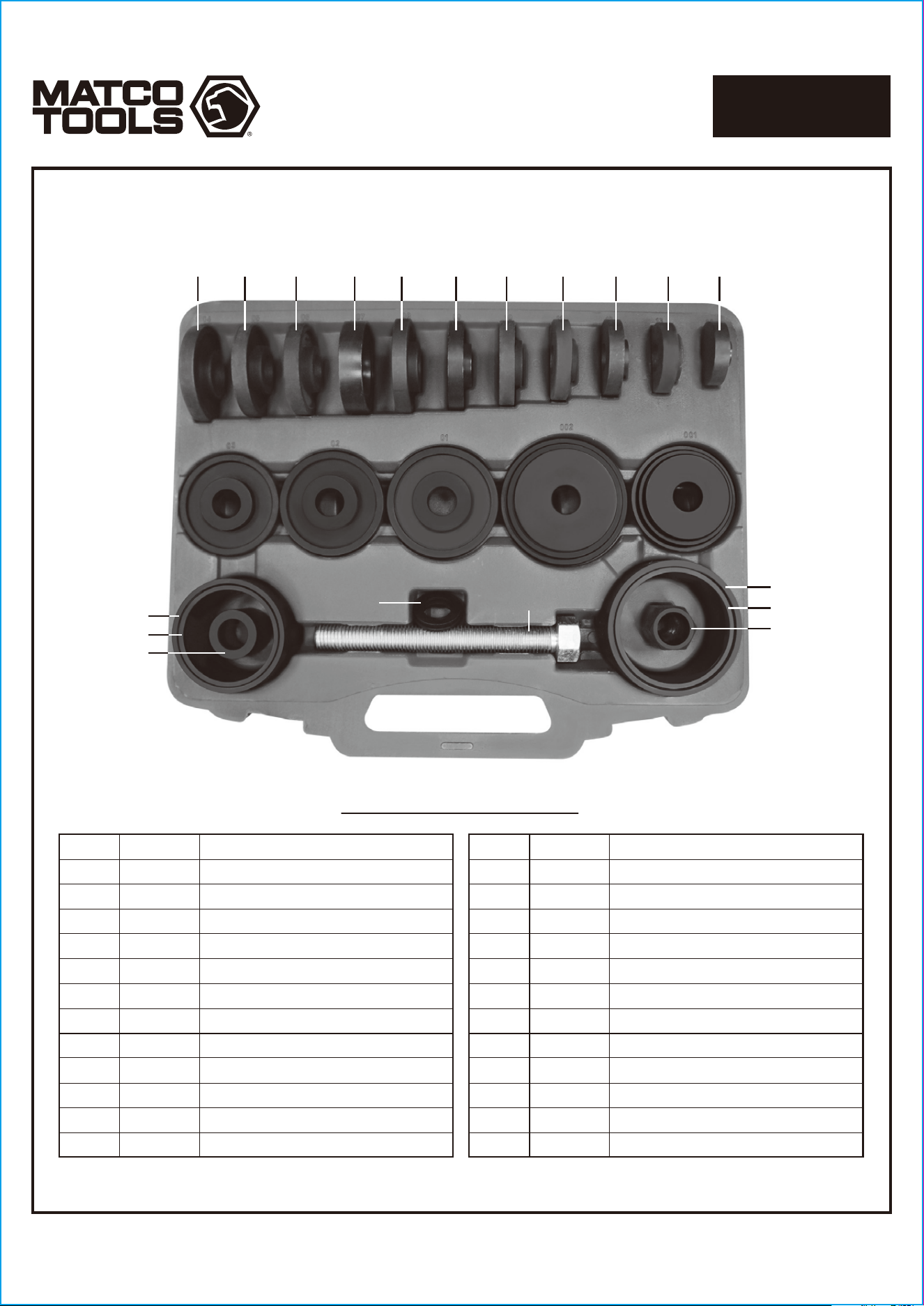
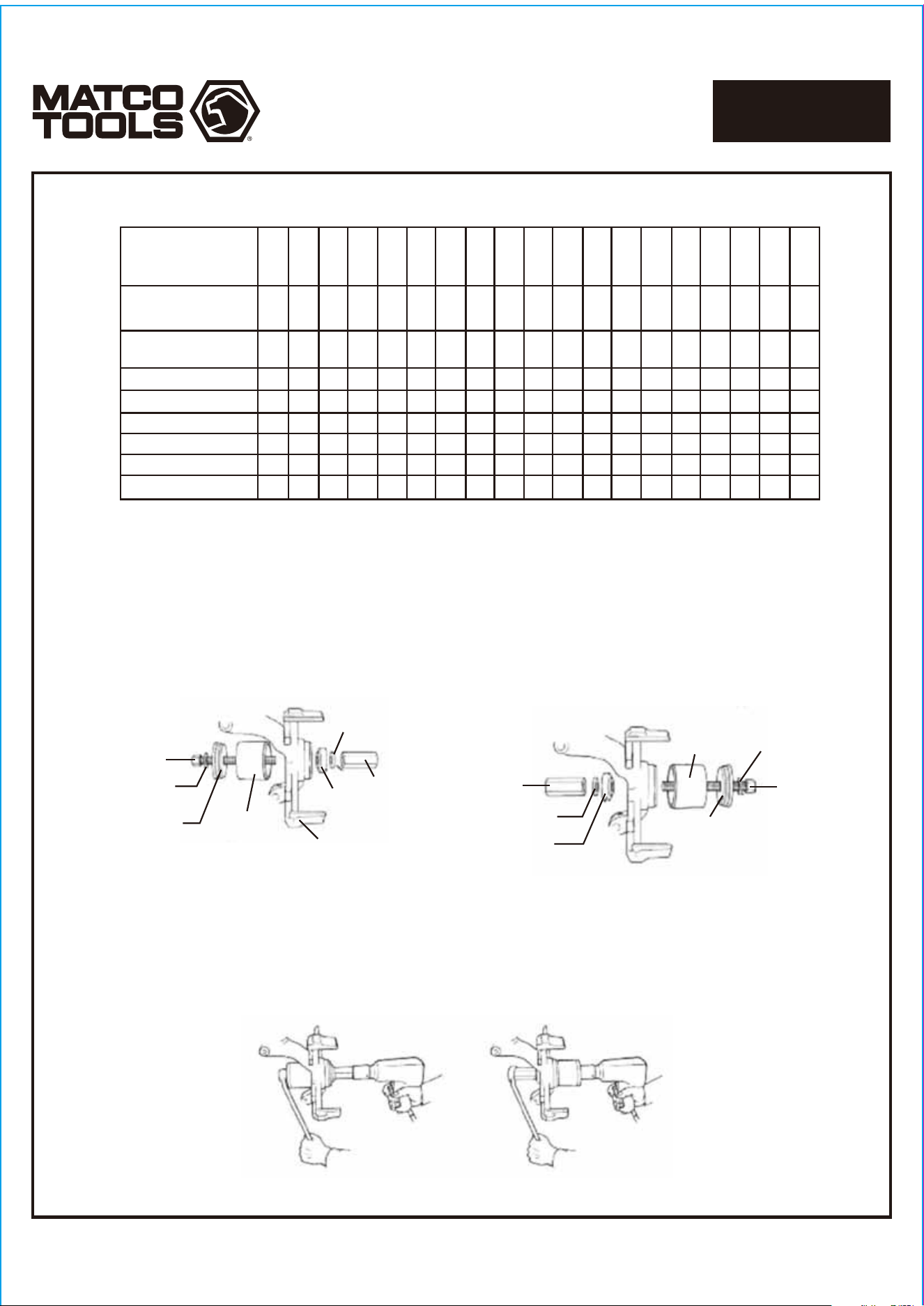
PARTS BREAKDOWN
Page 58
1712467-14
MASTER FRONT WHEEL
DRIVE BEARING ADAPTER KIT
MBA25
04
20
19 (x2)
18
21
22
05 06 07
03
23
02
01
24
08 09 10 11 12 13 14
15
16
17
PARTS BREAKDOWN
Index # Part # Description Index # Part # Description
01
02
03
04
05
06
07
08
09
10
11
12
13
14
15
16
17
18
19
20
21
22
23
24
MBA25-13
MBA25-14
MBA25-15
MBA25-16
MBA25-17
MBA25-18
MBA25-19
MBA25-20
MBA25-21
MBA25-22
MBA25-A
MBA25-B
MBA25-01
MBA25-02
MBA25-03
MBA25-04
MBA25-05
MBA25-06
MBA25-07
MBA25-08
MBA25-09
MBA25-10
MBA25-11
MBA25-12
Bushing (3.48" OD)
Bushing (3.27" OD)
Bushing (3.21" OD)
Bushing (3.05" OD)
Bushing (2.95" OD)
Bushing (2.89" OD)
Bushing (2.87" OD)
Bushing (2.9" OD)
Bushing (2.76" OD)
Bushing (2.62" OD)
Bushing (2.48" OD)
Bushing (2.32" OD)
Bushing (2.17" OD)
2" Plate
Sleeve (4" OD x 2.56")
Sleeve (3.6" OD x 2.56")
2.4" Nut
7/8" Grade 8 Bolt
Hardened Washer
Sleeve (3.4" OD x 2.56")
Sleeve (3" OD x 2.56")
Spacer
Small Sleeve Plate (3.4" x 2.7" Step)
Large Sleeve Plate (4" OD x 3.2" Step)
