Page 1 of 16 2004058-12
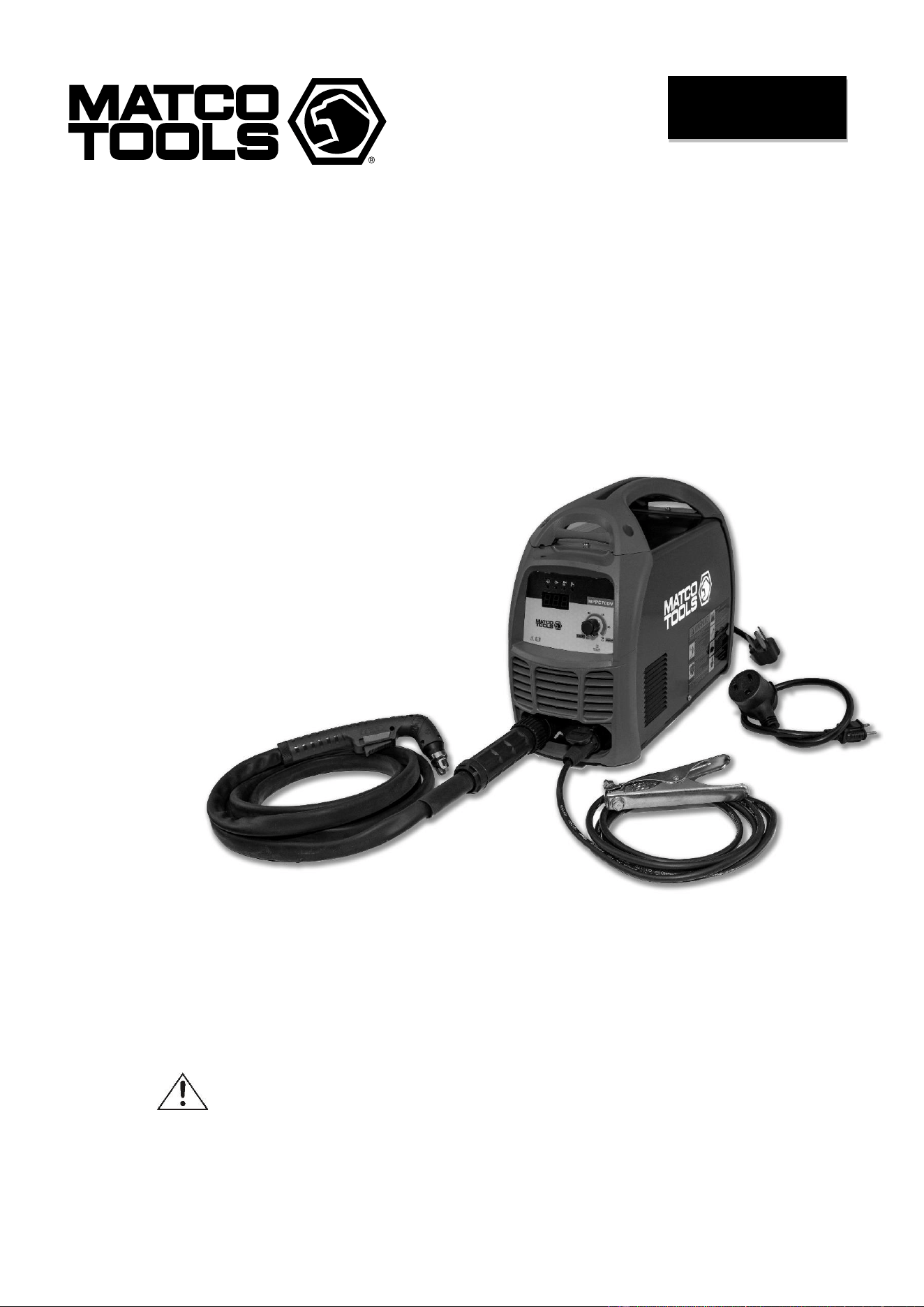
INVERTER DC
PLASMA CUTTER
OWNER’S MANUAL
11/2019
WARNING:
Read carefully and understand all ASSEMBLY AND OPERATION
INSTRUCTIONS before operating. Failure to follow the safety rules and other
basic safety precautions may result in serious personal injury.
MPPC70DV

Page 2 of 16 2004058-12
EFFECTIVE APRIL 1, 2015
LIMITED WARRANTY
This warranty applies to the original purchaser and is subject to the terms and conditions listed below.
This Limited Warranty is for new equipment sold after the above date, providing coverage for defects
in material and workmanship at the time it is shipped from the factory.
Limited to the warranty periods below, MATCO TOOLS will repair or replace the item under warranty
that fails due to defects in material and workmanship. MATCO TOOLS must be notified within 30 days
of the failure, to provide instructions on how to proceed with the repair of your welder and warranty
claim processing. Warranty period begins at the time the welder is purchased from an Authorized
MATCO TOOLS distributor. Keep your receipt as proof of purchase.
Warranty Periods
Limited Warranty is divided into these categories.
No Warranty, 1 year, 2 year and 3 year.
No Warranty
Normal wear items, MIG gun parts (contact tips,
nozzle, contact tip adapter, MIG gun liner), drive
roll, electrode holder, ground clamps, and
plasma torch parts (nozzle, electrode, diffuser,
cover) are considered consumable items and
are not covered under warranty.
1 Year Accessories Warranty
Parts and Labor on MIG gun parts (except those
listed under normal wear items), cables,
regulator, and plasma torch (except those listed
under normal wear items) are covered for 1 year.
Any shipping related to warranty repair is the
responsibility of the customer.
2 Year Welder Warranty
The 2 year warranty covers Parts and Labor on
items such as: transformer, reactor, rectifier,
solenoid valve, PC board, switches, controls,
gas valve, drive motor, drive system other than
drive roll and any other component that requires
the removal of the sheet metal to access. Any
shipping related to warranty repair is the
responsibility of the customer.
Voiding Warranty
Warranty does not apply to shipping damage,
misuse and abuse of the unit and alteration of
the unit in any way.
Warranty Claim
This is a Parts and Labor warranty. Contact the
MATCO TOOLS distributor you purchased
the unit from. Retain your receipt in the case a
warranty claim is needed. No warranty will be
provided without the original receipt from an
authorized MATCO TOOLS distributor. To make
a warranty claim, contact your MATCO TOOLS
distributor. That MATCO TOOLS distributor will
contact the customer service department for
warranty instructions.
Page 3 of 16 2004058-12
GENERAL SAFETY RULES
WARNING: Read and understand all
instructions. Failure to follow all instructions
listed below may result in serious injury.
CAUTION: Do not allow persons to
operate or assemble this unit until they have
read this manual and have developed a
thorough understanding of how this unit
works.
WARNING: The warnings, cautions,
and instructions discussed in this
instruction manual cannot cover all possible
conditions or situations that could occur. It
must be understood by the operator that
common sense and caution are factors which
cannot be built into this product but must be
supplied by the operator.
WARNING: This product can expose
you to chemicals including Lead, which is
known to the State of California to cause
cancer and birth defects or other reproductive
harm. For more information go
towww.P65warnings.ca.gov
SAVE THESE INSTRUCTIONS
IMPORTANT SAFETY CONSIDERATIONS
1.1 Your Welding/Cutting Environment
-Keep the environment you will be
welding/cutting in free from flammable
materials.
-Always keep a fire extinguisher accessible to
your plasma cutting/welding environment.
-Always have a qualified person install and
operate this equipment.
-Make sure the area is clean, dry and
ventilated. Do not operate the plasma cutter in
humid, wet or poorly ventilated areas.
-Always have your plasma cutter maintained by
a qualified technician in accordance with local,
state and national codes.
-Always be aware of your work environment. Be
sure to keep other people, especially children,
away from you while you are cutting.
-Keep harmful arc rays shielded from the view of
others.
-Mount the plasma cutter on a secure bench or
cart that will keep the plasma cutter secure and
prevent it from tipping over or falling.
1.2 Your Plasma Cutter’s Condition
-Check ground cable, power cord and torch
cable to be sure the insulation is not damaged.
Always replace or repair damaged components
before using the plasma cutter.
-Check all components to ensure they are clean
and in good operating condition before use.
1.3 Use of Your Plasma Cutter
Do not operate the plasma cutter if the torch is
wet. Do not immerse the plasma torch. Do not
stand in water while using this plasma cutter.
These components and the plasma cutter must
be completely dry before attempting to use it.
-Follow the instructions in this manual.
-Keep the plasma cutter in the off position when
not in use.
-Connect ground lead as close to the area
being cut as possible to ensure a good ground.
-Do not allow any body part to contact with the
material being cut, or to the ground or
electrode from another plasma cutter or welder.
-Do not cut if you are in an awkward position.
Always have a secure stance while cutting to
prevent
accidents. Wear a safety harness if working
above ground.
-Do not drape cables over or around your body.
- Wear eye protection (see ANSI Z49.1 safety
standard) while cutting to protect your eyes
from harmful UV and IR rays.

Page 4 of 16 2004058-12
-Wear proper gloves and protective clothing to
prevent your skin from being exposed to hot
metals, UV and IR rays.
-Do not overuse or overheat your plasma
cutter. Allow proper cooling time between duty
cycles.
-Keep hands and fingers away from moving
parts.
- Do not point the plasma torch at any body part
or at anyone else.
-Always use this plasma cutter in the rated duty
cycle to prevent excessive heat and failure.
1.4 Specific Areas of Danger, Caution or
Warning
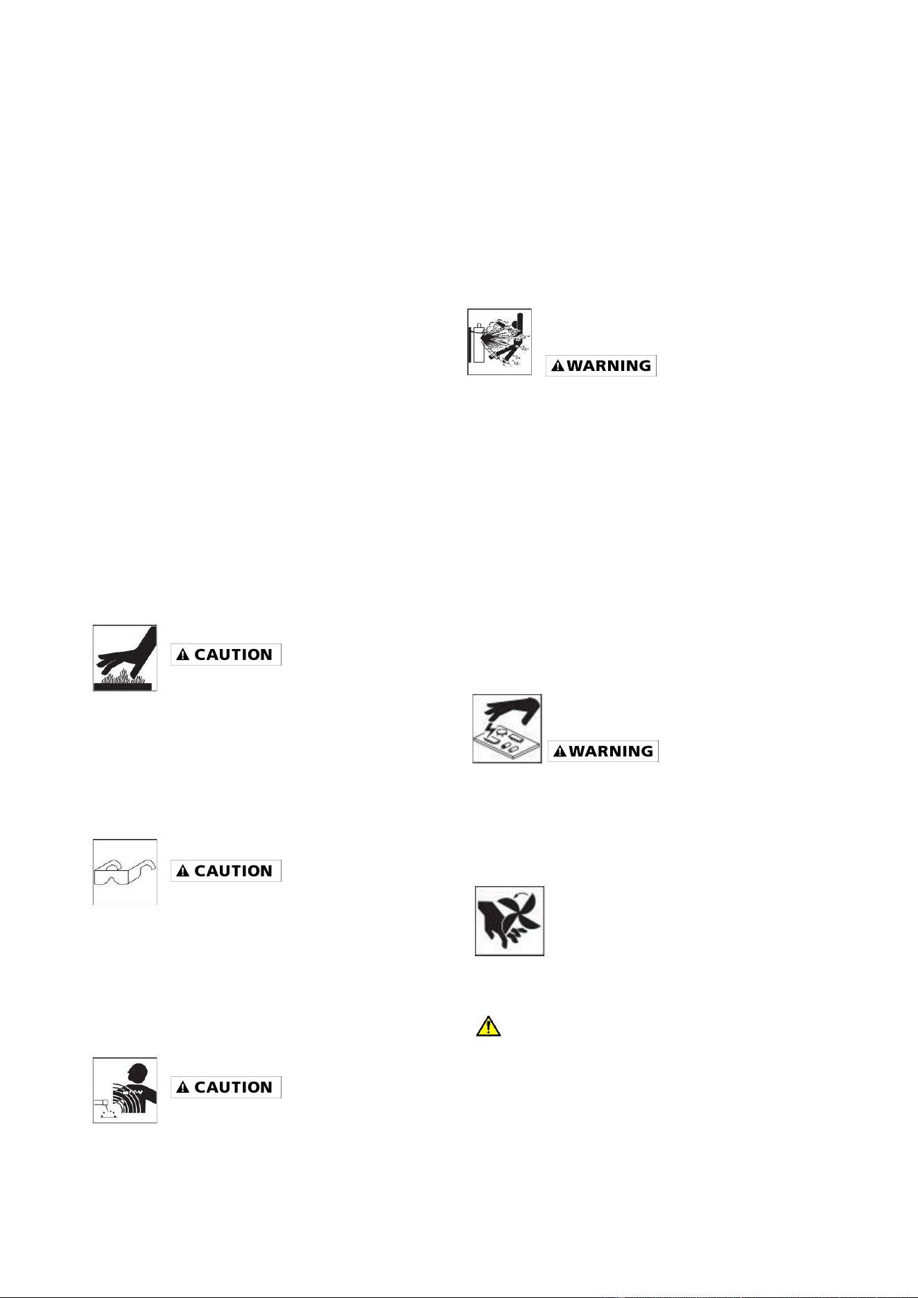
Electrical Shock
Plasma cutters can produce a
shock that can cause injury or
death. Touching electrically live parts can
cause fatal shocks and severe burns. While
cutting, all metal components connected to the
wire are electrically hot. Poor ground
connections are a hazard, so secure the
ground lead before cutting.
-Wear dry protective apparel: coat, shirt, gloves
and insulated footwear.
-Insulate yourself from the work piece. Avoid
contacting the work piece or ground.
- Do not attempt to repair or maintain the
plasma cutter while the power is on.
-Inspect all cables and cords for any exposed
wire and replace damaged or wore cables
immediately.
-Use recommended replacement cables and
cords.
-Always attach the ground clamp to the work
piece or worktable as close to the cutting area
as possible.
-Do not touch the torch and the ground or grounded work
piece at the same time.
Fumes and Gases
-Fumes emitted from the plasma
cutting process displace clean air and
can result in injury or death.
-Do not breathe in fumes emitted by the plasma
cutting process. Make sure your breathing air is
clean and safe.
-Work only in a well-ventilated area or use a
ventilation device to remove plasma cutting
fumes from the environment where you will be
working.
-Do not plasma cut on coated materials
(galvanized, cadmium plated or containing zinc,
mercury or barium). They will emit harmful
fumes that are dangerous to breathe. If
necessary, use a ventilator, respirator with air
supply or remove the coating from the material
in the area to be cut.
-The fumes emitted from some metals when
heated are extremely toxic. Refer to the
material safety data sheet for the
manufacturer’s instructions.
-Do not weld/cut near materials that will emit
toxic fumes when heated. Vapors from
cleaners, sprays and degreasers can be highly
toxic when heated.
UV and IR Arc Rays
The plasma cutting arc produces
ultraviolet (UV) and infrared (IR)
rays that can cause injury to your eyes and
skin. Do not look at the plasma cutting arc
without proper eye protection.
- Always use safety glasses, a shield or a
helmet that meets ANSI Z49.1 standard for
plasma cutting.
- Cover all bare skin areas exposed to the arc
with protective clothing and shoes. Flame-
retardant cloth or leather shirts, coats, pants or
coveralls are available for protection.
-Use screens or other barriers to protect other
people from the arc rays emitted from your
plasma cutting arc.
-Warn people in your cutting area when you are
going to strike an arc so they can protect
themselves.
Fire Hazards
Do not cut on containers or pipes that
contain or have had flammable,
Page 5 of 16 2004058-12
gaseous or liquid combustibles in them. Plasma
cutting creates sparks and heat that can ignite
flammable and explosive materials.
-Do not operate any plasma cutter in areas
where flammable or explosive materials are
present.
-Remove all flammable materials within 35 feet
of the plasma cutting arc. If removal is not
possible, tightly cover them with fireproof
covers.
-Take precautions to ensure that flying sparks
do not cause fires or explosions in hidden
areas, cracks or areas you cannot see.
-Keep a fire extinguisher close in the case of
fire.
-Wear garments that are oil-free with no
pockets or cuffs that will collect sparks.
-Do not have on your person any items that are
combustible, such as lighters or matches.
-Keep the work lead connected as close to the
plasma cutting area as possible to prevent any
unknown, unintended paths of electrical current
from causing electrical shock and fire hazards.
Hot Materials
Plasma cut materials are hot and can
cause severe burns if handled
improperly.
-Do not touch plasma cut materials with bare
hands.
- Do not touch torch tip after cutting until it has
had time to cool down.
Sparks/Flying Debris
Plasma cutting creates hot sparks
that can cause injury. Chipping slag off cuts
can create flying debris.
-Always wear protective apparel: ANSI-
approved safety glasses or shield, a welder’s
hat and ear plugs to keep sparks out of ears
and hair.
Electromagnetic Field
Electromagnetic fields can interfere
with various electrical and electronic
devices such as pacemakers.
-Consult your doctor before using any plasma
cutting device
-Keep people with pacemakers away from your
plasma cutting area while cutting.
-Do not wrap cable around your body while
plasma cutting.
- Wrap plasma torch cable and ground cable
together whenever possible.
- Keep plasma torch and ground cables on the
same side of your body
Shielding Gas Cylinders Can
Explode
High pressure cylinders can explode if
damaged, so treat them
carefully.
-Never expose cylinders to high heat, sparks,
open flames, mechanical shocks or arcs
-Do not touch cylinder with plasma torch.
-Do not plasma cut on the cylinder.
-Always secure cylinder upright to a cart or
stationary object
-Keep cylinders away from welding/cutting or
electrical circuits.
-Use the proper regulators, gas hose and fittings
for the specific application
Proper Care, Repair &
Maintenance
Always have power disconnected when
working on internal components.
-Do not touch or handle PC board without being
grounded with a wrist strap. Put PC board in
static proof bag to move or ship.
-Do not put hands or fingers near
moving parts such as drive or fan.
Proposition 65 Warnings
WARNING
Breathing welding fumes exposes you to
chemicals, including chromium (hexavalent
compounds), known to the State of California to
cause cancer and birth defects or other
reproductive harm. *Always weld in a well-

Page 6 of 16 2004058-12
ventilated area. * If in an enclosed area, vent
the exhaust to the outside. For more
information go to www.P65warings.ca.gov.
WARNING
This product can expose you to chemicals
including Lead, which is known to the State of
California to cause cancer and birth defects or
other reproductive harm. For more information
go to www.P65warings.ca.gov.
USE AND CARE
• Do not modify this unit in any way.
Unauthorized modification may impair the
function and/or safety and could affect the
life of the equipment. There are specific
applications for which this unit was
designed.
• Always check for damaged or worn out
parts before using this unit. Broken parts
will affect the operation. Replace or repair
damaged or worn parts immediately.
• Store idle. When this unit is not in use,
store it in a secure place out of the reach of
children. Inspect it for good working
condition prior to storage and before re-
use.
TECHNICAL SPECIFICATIONS
Item
Description
Power Supply
120V, 15A, 50/60 HZ, Single Phase
230V, 45A, 50/60 HZ, Single Phase
No-Load Voltage
310 Volts DC
Output Range
120V, 15A-23A
230V, 15A-45A
Duty Cycle
120V, 35% @ 23A
230V, 40% @ 45A
Compressed Air Required
4.5 CFM @ 60psi - DO NOT SUPPLY MORE THAN 100psi
Dimensions
18.58 x 7.32 x 13.46
Weight
22.93 lbs.
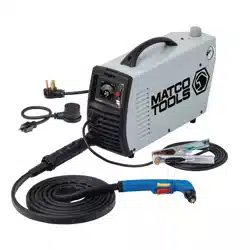
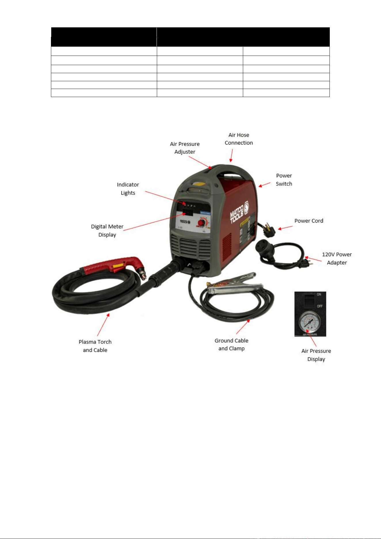
DESCRIPTION
The Matco Tools MPPC70 is a Dual Voltage, DC
Inverter Plasma Cutter. It uses new state of the
art technology. The output can be adjusted
from 15 to 45 Amps. This unit is designed to cut
up to 11/16" steel at a travel speed of 10 inches
per minute when operating on 230V AC power.
Use the included adapter cord to run this unit off
120V AC power for a cutting capacity on steel of
up to 1/4” at a travel speed of 10 inches per
minute. It cuts all electrically conductive
materials. See chart below. It cuts with a
narrow
kerf that results in a smaller heat affected zone
for reduced warping. The MPPC70 is
lightweight (22.93 lbs.), compact, inverter design
for greater portability. It has a pilot arc for easy
starts and enables the user to cut fence or
expanded metal. This unit has a built-in air
pressure adjustment and gauge, indicator lights
for quick trouble shooting and thermal overload
protection and now features a built-in water
separator. The electrode, nozzle, diffuser ring
and protective cap are consumable items and
available through your Matco distributor.
Page 7 of 16 2004058-12
Clean Cut
Clean Cut
Material
120V
230V
Mild Steel
1/4"
11/16"
Stainless Steel
1/4"
9/16"
Galvanized
1/4"
9/16"
Aluminum
3/16"
9/16"
Copper
3/16"
7/16"
Brass
3/16"
7/16"
AIR PRESSURE DISPLAY
The built-in air display is used for reading the
output gas pressure when cutting.
DIGITAL METER READ OUT
The digital meters allow for a more precise
setting to achieve the optimal setting for a more
exact cut.
AIR PRESSURE ADJUSTOR
It is used to adjust the air pressure. The air
pressure can be read from the air pressure
display on the back panel. Normally, when
operating on 230V power, the pressure should
be adjusted between 50-80psi. When operating
on 120V power, the pressure should be adjusted
between 45-65 psi.
POWER INDICATOR LIGHT
This light will turn on when the input power cord
is plugged into the power supply and the power
switch on the back of the plasma cutter is in the
"ON" position.
WORK INDICATOR
The work indicator will light when the torch

Page 8 of 16 2004058-12
trigger is pulled, indicating cutting current is
activated.
PROTECTION INDICATOR LIGHT
When the unit is in thermal overload, is over
voltage or lacking voltage, the indicator will be
on and cutting output will stop. Leave the unit on.
When the unit is cooled down and/or voltage
stabilizes, the Protection Indicator Light will turn
off and the unit will automatically start output
again.
LOW AIR INDICATOR LIGHT
This light will be on when the air pressure or air
flow is low.
CURRENT ADJUSTMENT
Variable adjust the output cutting current. The
higher output matches the thicker metal. The
maximum cutting thickness is up to 11/16″ for
this unit. Please note that the maximum cutting
thickness varies depending on the material type
you are cutting. See the table on the previous
page for reference. When operating on 120V
power, the output amperage is limited to 20A
only. Adjust the output current adjustment to 20A.
GROUND CABLE AND CLAMP
The ground cable clamp connects to your work
piece completing the electrical circuit. Without a
clean, rust and paint free connection, the arc will
not transfer from Pilot Arc to Cutting Arc.
PLASMA TORCH AND CABLE
The torch delivers compressed air and output
power that is needed to create the plasma arc.
AIR HOSE CONNECTION
The gas hose connection is on the back panel of
the plasma cutter. This connection requires a 1/4”
inch NPT connection (Not supplied). The other
end of the air hose connects to an air
compressor or compressed air supply. This
model now comes equipped with an internal air
water separator.
POWER SWITCH
The Power Switch allows input power to the
machine components. After the machine is
connected to the input power supply, turn on this
switch. The power indicator on the front panel
will turn on.
POWER CORD AND PLUG
Plug this unit into a 230V, 50A circuit breaker
power supply when operating on 230V. If
running on 120V power using the supplied
120V power cord adapter, plug this unit into a
120V, 20A circuit breaker power supply.
INSTALLATION
• High voltage danger from power source!
Consult a qualified electrician for proper
installation of receptacle. This cutter must
be Grounded while in use to protect the
operator from electrical shock.
• Do not remove grounding prong or alter
the plug in any way. Use only the supplied
adapter between the plasma cutter's power
cord and the power source receptacle. Make
sure the POWER switch is OFF when
connecting your plasma cutter's power cord
directly to a properly grounded 230 VAC, 60
HZ, Single Phase, 50 Amp input power
supply. Or, when using the supplied
adapter, connect the 120V Adapter to a
properly grounded 120V, 20 Amp input
power supply.
1. POWER REQUIREMENT 230V - AC
single phase 230V (200-240V) 50/60
HZ fused with a 50A time delayed fuse
or circuit breaker is required. DO NOT
OPERATE THIS UNIT if the ACTUAL
power source voltage is less than 215
volts AC or greater than 240 volts AC.
2. POWER REQUIREMENT 120V - AC
single phase 120V (110-130V) 50/60
HZ fused with a 20A time delayed fuse
or circuit breaker is required. DO NOT
OPERATE THIS UNIT if the ACTUAL
power source voltage is less than 110
volts AC or greater than 130 volts AC.
a. When connecting this unit to
120V power, connect the 120V
adapter cord to the power cord
pigtail that is attached to the
machine.
Page 9 of 16 2004058-12
3. EXTENSION CORD - We do not
recommend an extension cord because
of the voltage drop they produce. This
drop-in voltage can affect the
performance of the plasma
cutter/welder. If you need to use an
extension cord, we recommend you
check with a qualified electrician and
your local electrical codes for your
specific area. Do not use an extension
cord over 25 ft. in length.
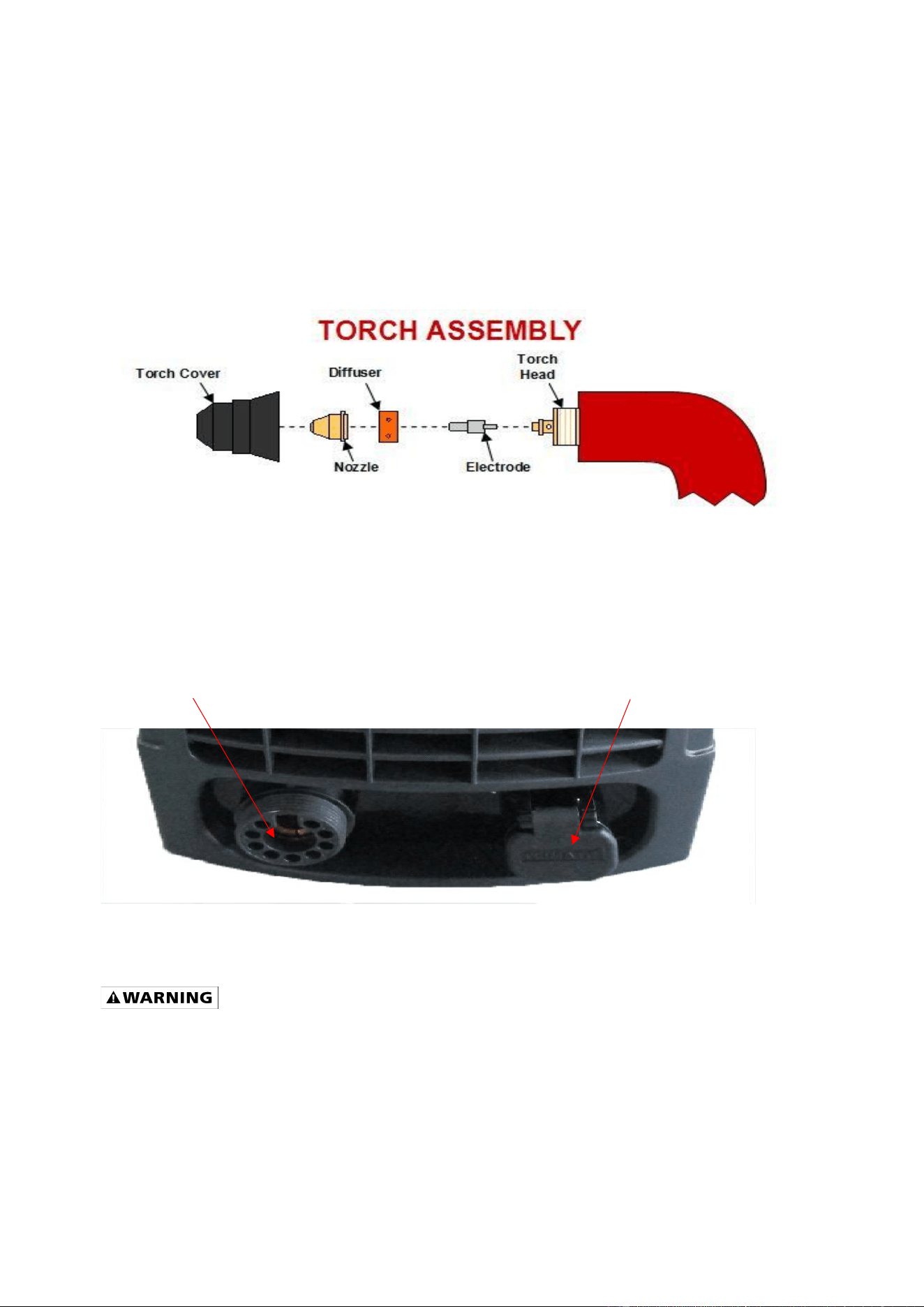
4. INSTALLATION OF THE CUTTING
TORCH CONSUMABLES
a. Your torch should be fully
assembled and ready to
operate. The below figure
shows the components of the
torch head and how those
components are installed.
b. Connect the Torch Control Cable to the Torch Trigger Control Connection. See Figure 3.
c. Connect the Grounding Cable to the ground connection. See Figure 3.
d. Connect the Ground Clamp to your workpiece
e. Connect your compressed air source to the air connection on this unit’s back panel.
Figure 3
OPERATION
High voltage danger from power source!
• Consult a qualified electrician for
proper installation of receptacle at
the power source. This plasma cutter
must be grounded while in use to
protect the operator from electrical
shock. If you are not sure if your
outlet is properly grounded, have it
checked by a qualified electrician.
• Do not cut off the grounding prong or
alter the plug in any way and do not
use any adapter, other than the
supplied adapter, between the
plasma cutter's power cord and the
power source receptacle.
• Make sure the POWER switch is OFF
then connect your plasma cutter's
Ground connection
Torch connection
Page 10 of 16 2004058-12
power cord to a properly grounded
230 VAC (220V - 240V), 60 HZ, single
phase, 50A power source. If operating
on 120V, attach the 120V Adapter cord
to the unit power cord and then
connect the assembly to a properly
grounded 120 VAC (110V-130V), 60 Hz,
single phase, 20A power source.
1. SET UP
a. Check the plasma cutter to see if it
has been connected correctly and is in
good working condition as described
in INSTALLATION Section and that it
complies with safe operation
requirements as noted in the
IMPORTANT SAFETY
CONSIDERATIONS Section.
b. Switch on the power switch of the
cutter to observe if the operation is
normal. If it is normal, the fan should
start up and the Power Indicator Light
should be on. If there is no compressed
air or the air pressure is low the Low-
Pressure Indicator Light will be on.
c. Adjust the air supply valve until the air
pressure is up to the cutting torch
requirement. (Lowest pressure should
be no less than 50psi), the Low-
Pressure Indicator Light will not be lit
up in those conditions.
d. Adjust the air flow to be sure it is
consistent.
e. Pull the torch trigger. The cutting
operation begins after the cutting
plasma pilot arc is made.
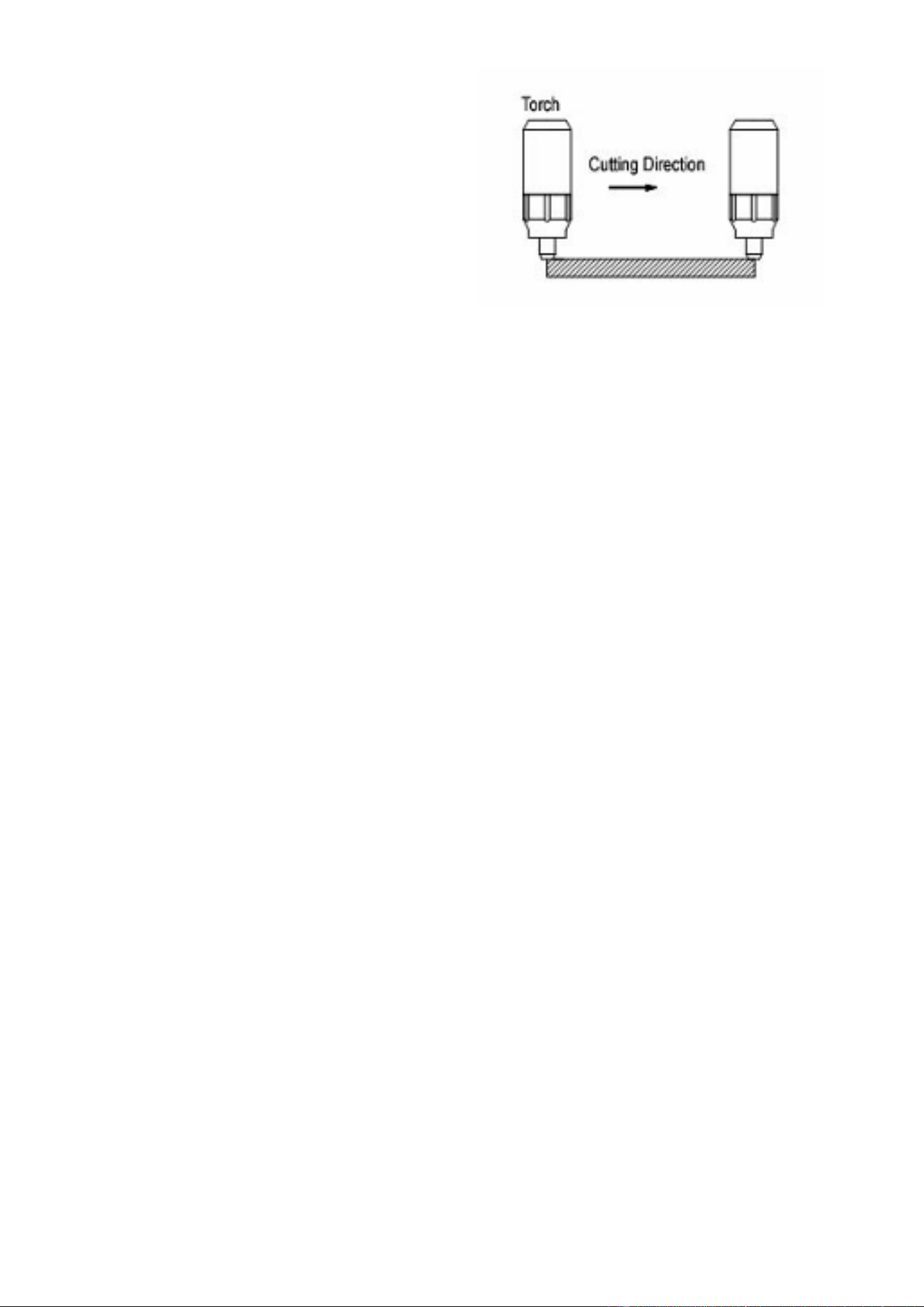
2. CUTTING OPERATION
2.1. Metal Sheet Cutting
a. Put the torch’s nozzle at the start
of the work piece. Turn on the
torch switch to ignite the plasma
pilot. After the work piece is cut
through, move the torch along the
cutting direction uniformly. The
cutting speed is determined by
watching to see if the cutting goes
all the way through. If the speed is
too fast, the work piece won’t be
cut through, or if too slow, the cut
quality would be affected,
excessive warping may occur, or
the arc could stop.
b. When you’ve completed the
cutting process, turn off the torch;
the plasma pilot arc will stop.
2.2. Metal Mesh Cutting
a. Fix the work piece and connect the
earth cable with the work piece.
b. Put the cutting nozzle onto the
work piece, lift torch up slightly
from the work piece and turn on
the switch to cut.
2.3. Notice while cutting
a. Unnecessary igniting of the pilot
arc in the air will reduce the
lifespan of the torch’s electrode
and nozzle.
b. It is best to start cutting at the edge
of the work piece, unless you are
piercing the work piece.
c. Keep a space between the nozzle
and the work piece. Pressing the
nozzle on the work piece could

Page 11 of 16 2004058-12
cause the nozzle to stick, reducing
the smoothness of the cutting
action creating an undesirable
result.
d. Keep the torch’s nozzle vertical
against the work piece and watch
to be sure the arc is moving along
the cutting line.
e. Do not rapidly switch the torch
trigger on and off; this will damage
the pilot arc system and work
piece.
f. The plasma cutter’s working air
pressure range is 50-90psi. Notice:
the internal pressure switch will
shut off when the air pressure falls
below 50psi. The switch only
works when the pressure rises to
50psi or above.
g. Every 4-8 hours check the air filter
on your air supply and remove
excess moisture. Too much
moisture in the cutter or torch may
lead to operational trouble.
Always unplug the power supply before
checking for and removing moisture.
3. SAFETY REQUIREMENTS
a. Never allow the torch to be aimed
at any part of a body.
b. Make sure to wear protective
glasses and gloves while operating.
c. Work only in well-ventilated areas.
If necessary, use exhaust/ventilation
fans to keep fumes or emissions away
from the breathing zone.
d. Do not touch the work piece while
cutting.
e. Do not cut pipes, containers, or
other materials that contain, or have
ever contained, flammable or explosive
materials.
f. Do not work underwater or in
wet/moist environments.
g. Do not bend the torch cable
sharply; this may damage the air hose.
h. Nobody other than the operator
should be allowed to access the
working area.
i. Always turn off the power supply
prior to repairing or moving the
machine.
j. Always turn off the power supply
prior to repairing or installing any spare
parts (e.g., torch, electrode, nozzle,
ground clamp, etc.).
k. Never allow a person with a
cardiac pacemaker close to the
working area without the permission of
a doctor. The magnetic field produced
by plasma cutters during operation can
disrupt pacemakers and similar
devices.
l. Do not allow the ground cable to
be pinched or damaged. If damaged,
replace immediately.
m. Never clean the slag off the torch
head by hitting it against a hard object.

Page 12 of 16 2004058-12
TROUBLESHOOTING
SYMPTOM
POSSIBLE CAUSE
CORRECTIVE ACTION
Unit does not power up
Unit is not plugged in
Plug unit in
Input power circuit breaker not on
Reset input power circuit breaker
Main power switch is defective
Replace main power switch
Control circuit board is defective
Replace control circuit board
No pilot arc
Low air supply pressure
Check air supply
Adjust gas pressure adjuster so the air
pressure display reads a minimum of 60psi
Protection indicator is on indicating the
machine is in protection mode
See protection indicator is on section below.
Missing torch head components
Replace missing torch head components.
See the INSTALLATION OF THE CUTTING
TORCH CONSUMABLES section.
Plasma torch trigger not communicating with
the unit
Pull the trigger. If the work light Is not on, the
torch Is not communicating with the
machine. Check trigger connection.
Replace or repair torch
Plasma torch may be defective
See if electrode in torch head Is spring
loaded. If it is not, the torch head has seized,
and the torch will need to be replaced. Install
an air dryer to your compressed air supply to
prevent corrosion of the torch head.
Arc start circuit defective
For assistance, contact Matco customer
service at 855-920-2399
Control circuit board is defective
Replace control circuit board
Control transformer defective
Replace control transformer
Have pilot arc but cutting arc does not ignite.
Work piece is painted or rusty
Remove all paint and rust
Ground clamp is connected where there is
paint or rust
Remove all paint and rust so ground clamp
is connected to bare metal
Ground clamp is not electrically connected to
the work piece
Make certain the ground clamp is connected
to the work piece
Protection indicator Is on
The internal temperature is too high.
Leave power on and let the fan cool the unit.
Output will continue when the unit has
cooled.
Input power voltage is too high or too low
Meter input power voltage. This unit must be
used with input voltage that ranges from
220V-240V AC (110V-130V when operating
using the 120V adapter cord).
Cooling fan is not working
Unit is not turned on
Turn on unit
Cooling fan defective
Replace the cooling fan
Control transformer defective
Replace control transformer
For Assistance, call 855-920-2399
Page 13 of 16 2004058-12
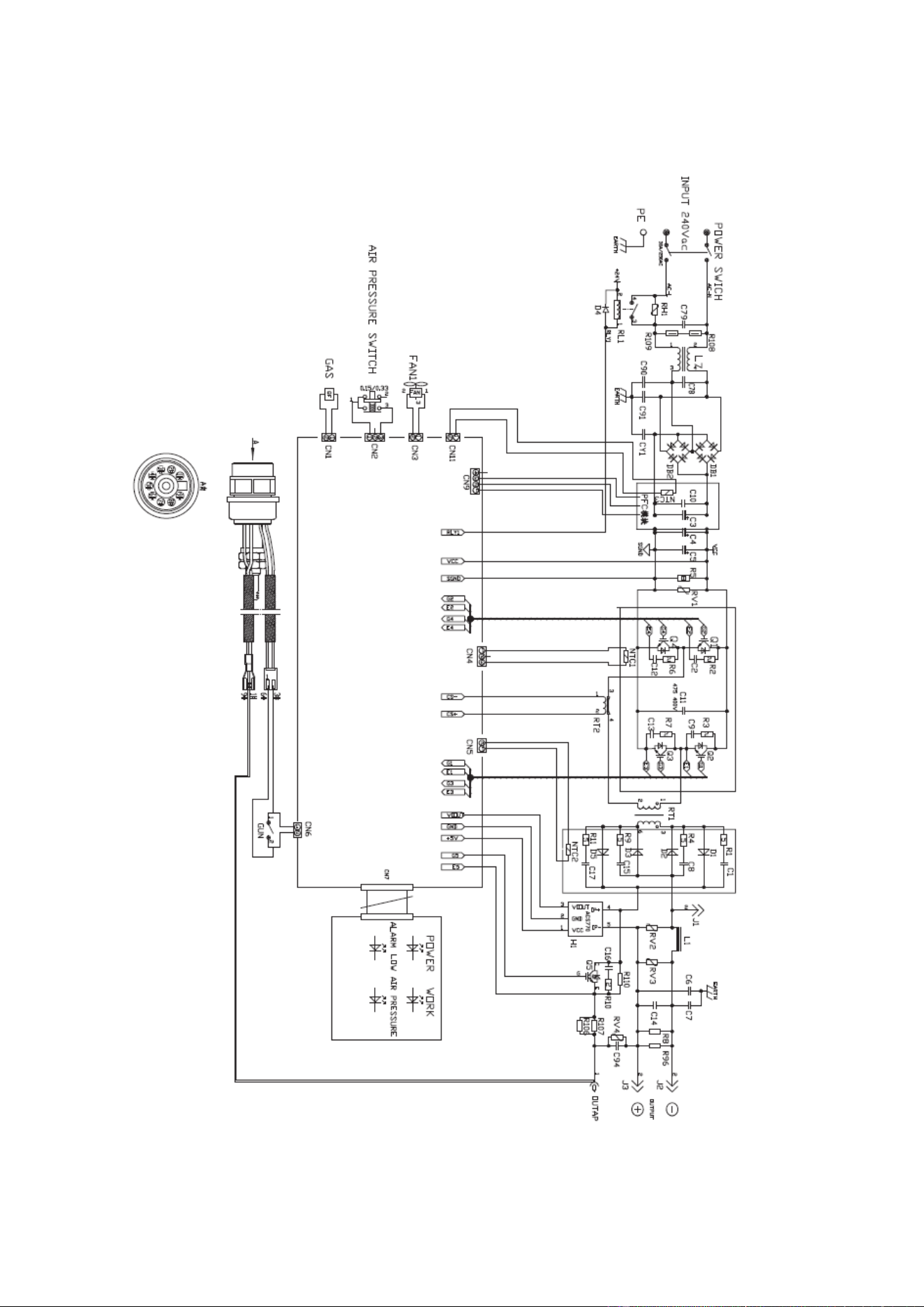
MAIN CIRCUIT DIAGRAM
Page 14 of 16 2004058-12
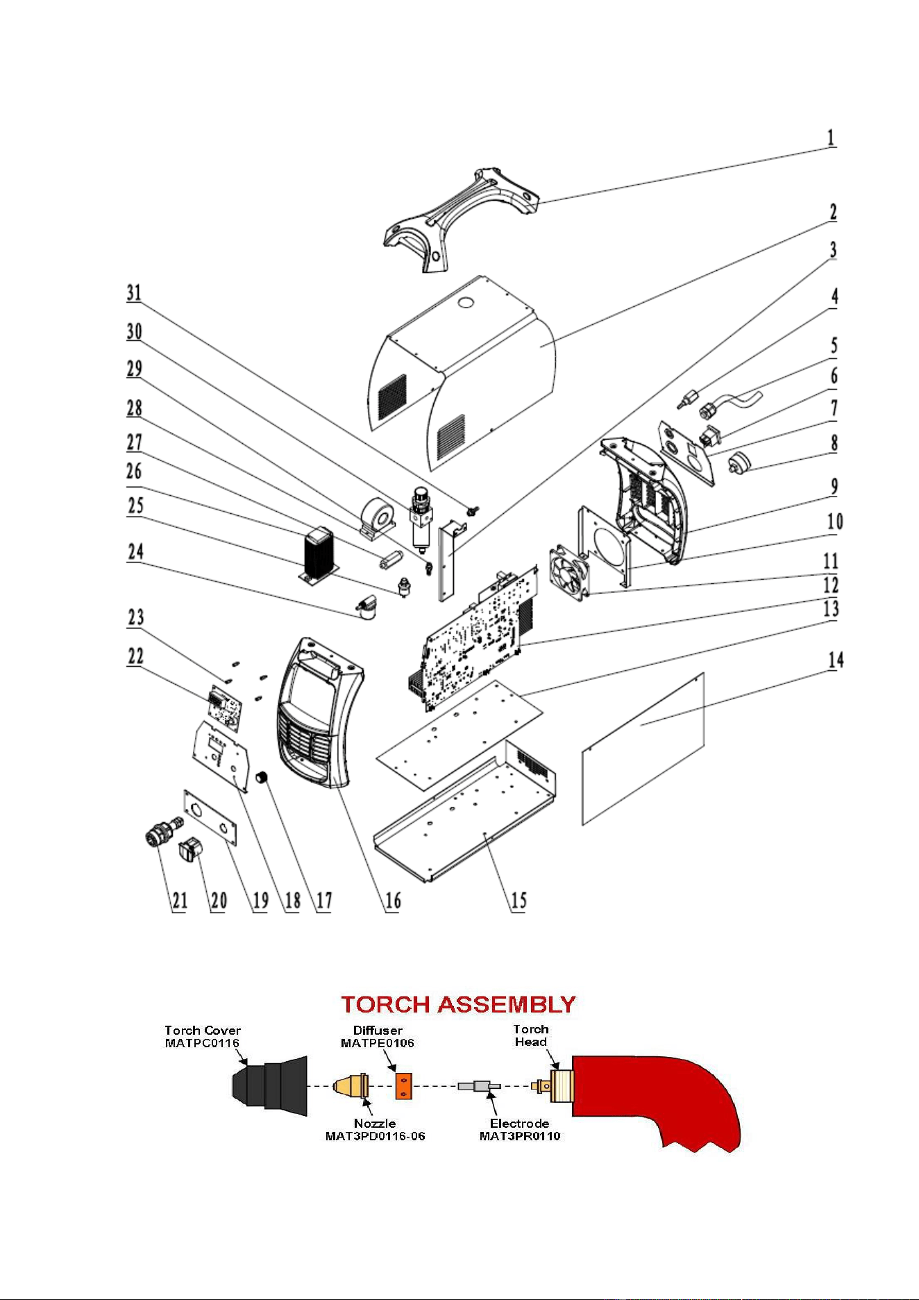
PARTS DIAGRAM

Page 15 of 16 2004058-12
PARTS LIST
REFERENCE
PART NUMBER
DESCRIPTION
QTY
1
165400012
HANDLE
1
2
165400013
ENCLOSURE
1
3
165400014
REGULATOR SUPPORT
1
4
165400015
INPUT GAS CONNECTOR
1
5
105200211
POWER CORD 220V
1
*
105200212
120V ADAPTER CORD
1
6
105400050
POWER SWITCH
1
7
165400016
BACK PANEL SUPPORT
1
8
105400061
AIR PRESSURE GAUGE
1
9
165400017
FRONT/REAR BEZEL
1
10
165400018
FAN SUPPORT
1
11
165400019
FAN
1
12
165400020
MAIN PCB
1
13
165400021
BASE INSULATING PLATE
1
14
165400022
PCB INSULATING PLATE
1
15
165400023
BASE PLATE
1
16
165400017
FRONT/REAR BEZEL
1
17
105400071
AMPERAGE ADJUSTMENT POTENTIOMETER
1
18
165400024
FACE PLATE SUPPORT
1
19
165400025
FRONT PANEL SUPPORT
1
20
105400154
GROUND CONNECTORY COVER
1
21
165400026
TORCH CONNECTOR
1
22
165400027
FACE PLATE PCB
1
23
165400028
COPPER TERMINAL
1
24
105400058
GAS SOLENOID VALVE
1
25
165400029
PRESSURE SWITCH
1
26
165400030
AC REACTOR
1
27
165400031
VALVE CONNECTOR
1
28
165400032
PFC RECTIFIER
1
29
105400139
AIR CONNECTOR
1
30
105400249
GAS VALVE WITH WATER SEPERATOR
1
*
ASSEMBLED ITEM
WATER SEPERATOR DRAIN HOSE
1
31
105400110
AIR PRESSURE REGULATOR
1
* ITEMS ARE NOT PICTURED
Replacement parts can be ordered through your Matco Tools Distributor
For technical questions, call 855-920-2399.

Page 16 of 16 2004058-12
Distributed by
Matco Tool
4403 Allen Road
Stow OH 44224
ww w . m a t c o t o o l s . c o m
Made in China
to Matco specifications